data integrity and availability in power system communication
TRANSCRIPT

Data Integrity and Availability in PowerSystem Communication Infrastructures
OGNJEN VUKOVIC
Licentiate ThesisStockholm, Sweden 2013


Data Integrity and Availability in Power SystemCommunication Infrastructures
OGNJEN VUKOVIC
Licentiate thesisStockholm, Sweden, 2013

TRITA-EE 2013:016ISSN 1653-5146ISBN 978-91-7501-772-3
School of Electrical EngineeringKTH, Stockholm, Sweden
Akademisk avhandling som med tillstand av Kungl Tekniska hogskolan framlaggestill offentlig granskning for avlaggande av licentiatexamen torsdagen den 30 Maj2013 i Horsal F3, KTH, Stockholm.
c© Ognjen Vukovic, Maj 2013
Tryck: Universitetsservice US AB
i
Abstract
Society is increasingly dependent on the proper functioning of electricpower systems. Today’s electric power systems rely heavily on informationand networking technology in order to achieve efficient and secure operation.Recent initiatives to upgrade power systems into smart grids target an eventighter integration with information and communication technologies in orderto enable the integration of renewable energy sources, local and bulk genera-tion and demand response. Therefore for a proper functioning of smart grids,it is essential that the communication network is secure and reliable both inthe face of network failures and in the face of attacks. This thesis contributesto improving the security of power system applications against attacks on thecommunication infrastructure. The contributions lie in two areas.
The first area is the interaction of network and transport layer proto-cols with power system application layer security. We consider single andmulti-area power system state estimation based on redundant telemetry mea-surements. The state estimation is a basis for a set of applications usedfor information support in the control center, and therefore its security isan important concern. For the case of single-area state estimation, we lookat the security of measurement aggregation over a wide area communicationnetwork. Due to the size and complexity of power systems, it can be pro-hibitively expensive to introduce cryptographic security in every componentof the communication infrastructure. Therefore, we investigate how the ap-plication layer logic can be leveraged to optimize the deployment of network,transport and application layer security solutions. We define security metricsthat quantify the importance of particular components of the network infras-tructure. We provide efficient algorithms to calculate the metrics, and thatallow identification of the weakest points in the infrastructure that have to besecured. For the case of multi-area state estimation, we look at the securityof data exchange between the control centers of neighboring areas. Althoughthe data exchange is typically cryptographically secure, the communicationinfrastructure of a control center may get compromised by a targeted trojanthat could attack the data before the cryptographic protection is applied or af-ter it is removed. We define multiple attack strategies for which we show thatthey can significantly disturb the state estimation. We also show a possibleway to detect and to mitigate the attack.
The second area is a study of the communication availability at the appli-cation layer. Communication availability in power systems has to be achievedin the case of network failures as well as in the case of attacks. Availability isnot necessarily achieved by cryptography, since traffic analysis attacks com-bined with targeted denial-of-service attacks could significantly disturb thecommunication. Therefore, we study how anonymity networks can be usedto improve availability, which comes at the price of increased communicationoverhead and delay. Because of the way anonymity networks operate, onewould expect that availability would be improved with more overhead anddelay. We show that surprisingly this is not always the case. Moreover, weshow that it is better to overestimate than to underestimate the attacker’scapabilities when configuring anonymity networks.

ii
Acknowledgments
I would like to thank my main advisor Assoc. Prof. Gyorgy Dan for his guidance,and for his very helpful and continuous feedback. I am deeply grateful for all ourinsightful discussions that helped me in enhancing my knowledge, and in identifyingand addressing exciting research problems. I would also like to thank my second,but originally main advisor, Prof. Gunnar Karlsson, for giving me an opportunity tojoin this lab, and for introducing me into the world of scientific research. I am thank-ful for his support and for his comments on my work. Furthermore, I am grateful toall colleagues in the LCN for providing a friendly and stimulating work atmosphere.
I am thankful to all my friends in Stockholm, back home, and abroad, who werealways there for me, and whose presence was invaluable to me. Last but not least,I would like to thank to my family for their continuous support. Among them, myspecial gratitude goes to my mother Milka and my sister Jovana for their love andunderstanding.

Contents
Contents iii
1 Introduction 1
2 Power System Communication Infrastructures 52.1 SCADA Communication . . . . . . . . . . . . . . . . . . . . . . . . . 52.2 Inter-Control Center Communication . . . . . . . . . . . . . . . . . . 14
3 Power System State Estimation 173.1 Transmission Network Model . . . . . . . . . . . . . . . . . . . . . . 173.2 Measurement Model . . . . . . . . . . . . . . . . . . . . . . . . . . . 183.3 Single-area State Estimation . . . . . . . . . . . . . . . . . . . . . . . 193.4 Multi-area State Estimation . . . . . . . . . . . . . . . . . . . . . . . 22
4 Summary of original work 25
5 Conclusions and Future work 29
Bibliography 33
Paper A: Network-aware Mitigation of Data Integrity Attacks on PowerSystem State Estimation . . . . . . . . . . . . . . . . . . . . . . . . . . . . . . . . 37
Paper B: On the Security of Distributed Power System State Estimationunder Targeted Attacks . . . . . . . . . . . . . . . . . . . . . . . . . . . . . . . . . 61
Paper C: Traffic Analysis Attacks in Anonymity Networks: RelationshipAnonymity-Overhead Trade-off . . . . . . . . . . . . . . . . . . . . . . . . . . . . 79
iii


Chapter 1
Introduction
The main role of power systems transmission and distribution networks is to supplyconsumers with the electrical energy produced by electric generators. Transmissionnetworks transfer the energy over long distances, and they may contain a largenumber of substations interconnected by transmission lines, forming a mesh networktopology. In order to minimize the energy loses, the electrical energy is transmittedat high voltages, typically ranging from 100 kV to 500 kV [43]. When close toconsumers, step-down transformers are used to decrease the voltage levels beforeconnecting to the distribution networks that transmit the energy at lower voltagelevels, typically under 70 kV [43]. Distribution networks transfer the energy betweenthe transmission network and the consumers, and they typically operate in a radialconfiguration: feeders emanate from substations and form a tree structure withtheir roots at the substation and branches spreading over the distribution area [43].
A power system operates in one of three possible operating states: normal,emergency and restorative [30]. Normal operating state means that all the loads,i.e., power demanded by the consumers, can be supplied by the active generatorsthrough the transmission and distribution network without violating any operatingconstraints, such as bounds on the transmission line power flows. Normal operatingstate can be secure or insecure. The normal operating state is secure if the sys-tem can reside in the normal operating state after experiencing a contingency froma list of critical contingencies. Typically considered contingencies are outages oftransmission lines and generators. Contrary, the normal operating state is insecureif the system may not preserve the normal operating state after the occurrence ofsome contingency from the list. In this case, some actions must be taken so that thesystem is moved to the normal operating secure state, and therefore the emergencyoperating state is avoided. However, the system may still move to the emergencyoperating state, e.g., in event of a non-considered contingency. Emergency oper-ating state means that some of the operating constraints may be violated. In thisstate, instant actions are required to avoid the system collapse and to return thesystem to the normal operating state. The actions may result in disconnecting some
1

2 CHAPTER 1. INTRODUCTION
parts of the system, such as loads and generators. This may stabilize the system,where all operating constraints are satisfied again. However, the balance betweenthe generated and consumed power may have to be restored. The system is thenin the restorative operating state.
Power systems need to be continuously monitored and controlled so that thesystem is preserved in, or timely restored to, the normal operating secure state.The monitoring and control are performed through Supervisory Control And DataAcquisition (SCADA) systems, which rely on the power system communicationinfrastructure to deliver messages over wide area networks [35]. Remote measure-ments can be collected over the communication infrastructure, and used to deter-mine the operating state. The operating state can be described by a network modeland the voltage phasors at power system buses [2]. The voltage phasors are calledstate variables, and the set of voltage phasors is called the static state of the sys-tem [2]. If the collected measurements are the voltage phasors of all buses, thenthe static state of the system can be directly obtained. However, typically collectedmeasurements are power injections and power flows. Such measurements need to beprocessed so that the static state of the system can be determined. Moreover, themeasurements are prone to errors, and it may not be economically or technicallyfeasible to provide the measurements of every power flow and power injection in thesystem. Therefore, the idea of estimating the system state based on the networkmodel and the collected imperfect measurements was proposed in [37]. The abilityto estimate the state of the system provides the foundation for the establishmentof Energy Management Systems (EMS). EMS is a suit of applications used to op-erate the power system, and includes applications such as the contingency analysis,used to evaluate how an outage would affect the system, and the optimal powerflow, used to estimate the optimal power flows based on particular criteria, e.g.,minimization of the cost of generation or minimization of transmission line losses.
Power systems are highly dependent on proper functioning of their communi-cation infrastructures. The power system communication infrastructures should besecure and reliable both in the face of network failures and in the face of attacks.Security of communication infrastructures has three aspects: data confidentiality,data integrity, and data availability [36]. Data confidentiality protects the privacy(readability) of the data against unauthorized users, and it can be achieved by dataencryption. Data integrity protects the data against unauthorized generation andmodification, and it can be achieved by message authentication codes. Finally, dataavailability ensures data accessibility without excessive delay. Among these threeaspects, the emphasis is on data integrity and data availability, since incorrect orundelivered control actions and measurements could be more harmful than theirdisclosure [23, 24, 41].
Traditionally, security and reliability of power system communication infras-tructures have been achieved by isolating the communication infrastructure, and byprotecting the system design and implementation. However, power system commu-nication infrastructures are becoming more and more integrated with other com-munication infrastructures, including public ones. Moreover, some parts of the
3
system design, e.g., the communication protocols, have been standardized, and aretherefore known. Due to concerns about the cyber security of their systems, powersystem operators have started applying commercial security solutions, such as cryp-tographic protection, in their communication infrastructures. However, due to thesize of the systems, it may be economically and practically unfeasible to protect theentire system. Therefore, it is important to understand how secure is the system.One could start by identifying potential consequences for power systems, if any se-curity aspect of the communication infrastructure gets violated. Then, the securityof a power system communication infrastructure could be evaluated as how wellthe infrastructure prevents the consequences based on applied security solutions.Finally, one could identify how to efficiently deploy commercial security solutions inorder to minimize the consequences. If, however, the commercial security solutionscannot mitigate the consequences, additional solutions need be explored.
The objectives of this thesis are to:
• Investigate how violations of data integrity in the power system communi-cation infrastructure can affect power system applications, in particular thepower system state estimation.
• Define security metrics that can be used to evaluate the security of powersystem infrastructures, considering the power system state estimation.
• Analyze how data availability can be improved using anonymity networks.
The structure of this thesis is as follows. In Chapter 2, we discuss protocols andarchitectures used in power system communication infrastructures, and elaborateon data integrity and data availability provided by the infrastructures. In Chapter3, we describe power system state estimation, and discuss how a violation of dataintegrity can affect the state estimation. Chapter 4 provides a summary of thepapers included in this thesis along with the thesis’ author contributions to eachpaper. Chapter 5 summarizes the main findings and conclusions, and outlinespotential directions for future research.


Chapter 2
Power System CommunicationInfrastructures
Power systems rely heavily on their communication infrastructure for secure and re-liable operation [38]. The communication infrastructure serves two main roles. Thefirst role is to connects the control center with field devices so that measurementscan be acquired and remote control can be performed. This is the basis for Supervi-sory Control and Data Acquisition (SCADA) systems, used by an operator to mon-itor and control the system [3], and a core component of Phasor Networks, wherePhasor Data Concentrators aggregates measurements from Phasor MeasurementUnits (PMUs). The second role is to connects the control centers of interconnectedpower systems in order to improve operational efficiency and system stability. Thisenables the secure operation of large and highly inter-connected systems such asWestern Interconnect (WECC) in the U.S. and ENTSO-E in Europe.
2.1 SCADA Communication
SCADA system delivers information from sensors and relays through Remote Ter-minal Units (RTUs) to SCADA severs, and delivers control messages from SCADAservers through RTUs to relays. Sensors provide various measurements includingpower flows, voltages and currents. Relays control electrical circuits in order toautomatically reconfigure a circuit if a fault is detected (protective relays), or toreconfigure a circuit on demand by remote control (control relays). An RTU is aprogrammable device located at a substation, and is used to collect measurementsfrom the sensors, to monitor the status of protective relays, and to deliver commandsto the control relays. RTUs deliver the measurements and the status informationto a SCADA server over a Wide-Area Network (WAN), and receive commands forthe control relays from the SCADA server over the WAN. The SCADA server is thecentral processor of the SCADA system located at the control center, and usuallyprovides a human interface for monitoring and control.
5

6CHAPTER 2. POWER SYSTEM COMMUNICATION INFRASTRUCTURES
SCADA WAN
The types of WANs used for the communication between RTUs and SCADA serverscan include point-to-point connections over dedicated lines, circuit switched net-works, packet switched networks, and cell switched networks. In the case of point-to-point connections over dedicated lines, there is a separate line for every RTUto a SCADA server connection. The advantage of this solution is that it can pro-vide the best quality of service, but the main disadvantage is the cost, since a lineper RTU needs to be built or leased. Circuit switched networks provide dedicatedcommunication channels between RTUs and SCADA servers. Unlike for the caseof dedicated lines, communication channels in circuit switched networks are notalways active, they are established and used when needed so the network resourcescan be shared among many pairs of end points. Examples of technologies usedare Frequency Division Multiplexing (FDM), where each communication channelgets a non-overlapping frequency range, and Time Division Multiplexing (TDM),where each communication channel gets recurrent fixed-length time slot. In packetswitched networks, one communication channel may be shared by many partici-pants, who communicate by exchanging variable-length packets. Examples of suchtechnologies are X.25, Frame relay, GPRS, and Ethernet. Finally, cell switchednetworks are similar to packet switched networks, but they use fixed, instead ofvariable, length packets (cells). Prior transporting, data is divided into fixed-lengthcells. An example of such technology is Asynchronous Transfer Mode (ATM).
In principle, the communication infrastructure used for the WAN can be ownedby the operator, e.g., optical ground wires (OPGW) that run between the topsof high-voltage transmission towers, or leased, e.g., PSTN, Public Land MobileNetworks (PLMN), and satellite networks. In practice, the infrastructure is mostlyowned by the power system operator for reliability reasons. However, the increasingdemands imposed on the communication infrastructure by smart grid technologiesmay make it more economically efficient for the operators to lease commercial net-works than to deploy their own.
SCADA/RTU communication protocols
Historically, the SCADA communication protocols were independently designedby different SCADA equipment manufacturers. Each manufacturer developed theprotocols to be a part of its proprietary system, and to meet its specific needs [6].These proprietary protocols had disadvantages for the user, the user could not com-bine equipment produced by different manufacturers. With the increasing use ofSCADA systems, these disadvantages were becoming more prominent, and the needfor open standards was recognized [6]. To address the issues, standards organiza-tions were working on defining open protocols that would provide interoperabilitybetween systems. One of the arising standards was the IEC 60870-5 standard, cre-ated and progressively published from 1990 by the International Electro-technicalCommission (IEC) Technical Committee (TC) 57 [35]. IEC 60870-5 is a foundation
2.1. SCADA COMMUNICATION 7
for today’s most commonly used protocols for the communication between RTUsand SCADA servers: IEC 60870-5-104 (including its predecessor IEC 60870-5-101),and Distributed Network Protocol 3 (DNP3). IEC 60870-5-101 and IEC 60870-5-104 are predominantly used in Europe, while DNP3 is predominantly used in Northand South America, South Africa, Asia, and Australia [6].
IEC 60870-5
IEC 60870-5 is a part of the IEC 60870 standard, that defines operating conditions,electrical interfaces, performance requirements, and data transmission protocols.IEC 60870-5 defines communication protocols used for sending basic telecontrolmessages between two systems. IEC 60870-5 is based on the Enhanced Perfor-mance Architecture (EPA) model, which is a simplified version of the InternationalStandards Organization (ISO) Open Systems Interconnection (OSI) model [35].EPA is designed to provide optimum performance for telecontrol applications, andit defines only three layers: physical layer, link layer, and application layer. Thephysical layer is defined by IEC 60870-5-1, in particular, coding, formatting, biterror check, and synchronization of data frames of variable and fixed lengths. It in-cludes the specification of four frame formats. IEC 60870-5-2 defines the link layer:link transmission procedures using a control field and address field. IEC 60870-5-3defines how the application data units are structured in transmission frames. IEC60870-5-4 provides rules for defining information data elements, such as process vari-ables that are frequently used by the applications. Finally, IEC 60870-5-5 specifiesstandard services (functions) of the application layer which serve as basic guidelineswhen creating application profiles for specific tasks. Each application profile usesa specific set of functions. If there is a function needed by the application but notspecified in the standards, it should be specified within the profile.
IEC 60870-5-101 (IEC 101)
IEC 101, published in 1995, was the first IEC complete working SCADA protocolunder IEC 60870-5 [35]. It was designed to provide all necessary application levelfunctions for telecontrol applications that operate over large geographical areas,using low bandwidth point-to-point links.
IEC 101 uses the FT1.2 frame format defined in IEC 60870-5-1 [6]. On the linklayer, IEC 101 uses some selected transmission procedures from IEC 60870-5-2 thatmay be used for reliable transfer, and it supports unbalanced (only server initiatedmessage exchange) and balanced (both server and client can initiate the exchange)transmission modes. IEC 101 defines Application Service Data Units (ASDUs) froma given general structure in IEC 60870-5-3, which are used for structuring transmis-sion frames. The contents and sizes of fields in ASDUs are specified according toIEC 60870-5-4. The basic application functions utilized by IEC 101 include cyclicdata transmission, data acquisition by polling, command transmission, acquisitionof events, etc., and are defined in IEC 60870-5-5.

8CHAPTER 2. POWER SYSTEM COMMUNICATION INFRASTRUCTURES
Start byte (1 byte = 0x10)
Link control field (1 byte)
Link address fields
(up to 2 bytes)
Checksum (1 byte)
Stop byte (1 byte = 0x16)
Indicates the start of frame
Control functions
Device / server address
Error check
Indicates the end of frame
Fixed length frame format
Field name Field description
Start byte (1 byte = 0x68)
Length (1 byte)
Length - copy (1 byte)
Start byte (1 byte = 0x68)
Link control field (1 byte)
Link address fields
(up to 2 bytes)
Checksum (1 byte)
Stop byte (1 byte = 0x16)
Indicates the start of frame
Length of Link layer data (control field,
address fields, and link user data) in bytes
Copy of the start for reliability
Control functions (e.g., message direction)
Device / server address
Error check
Indicates the end of frame
Variable length frame format
Field name Field description
Link user data
(up to 253 bytes)Application Service Data Unit (ASDU)
Single character frame
Acknowledgment (1 byte = 0xE5) Used for acknowledgments
Field name Field description
Figure 2.1: Three FT1.2 frame forms used by IEC 101. The figure is based on [6].
The FT1.2 frame format has three forms: variable-length frame format, fixed-length frame format, and a single character frame [6]. The variable-length frame isused for bidirectional data transmission between the server and the remote station.The fixed-length frame format is be used for commands, and it can be used foracknowledgments. The single character frame consists of just one byte, and it canbe only used for acknowledgments. The structures of the three forms of the FT1.2frame are given in Figure 2.1 (based on [6]). IEC 101 provides addressing on thedata link layer through the link address field in the FT1.2 frame format [6]. Thelink address field can be from 0 to 2 bytes for the balanced transmission mode, orfrom 1 to 2 for the unbalanced transmission mode. Since the balanced transmissionmode may go through a point-to-point link, the link address is redundant. In thatcase the link address can be omitted.
IEC 101 provides detection of bit transmission errors through checksum providedby FT1.2 [6]. FT1.2 uses an 8-bit checksum calculated as the modulo 256 sum ofthe link layer data [6], which is the data that starts after the second start fieldand ends before the checksum field (Figure 2.1). By recalculating the checksum onthe receiver side, bit errors due to transmission can be detected but not corrected.If the checksum detects the transmission errors, the data is discarded and a re-transmission is requested. However, it may happen that many bit errors occur sothat the 8-bit checksum calculation results in the same 8 bits as in the case withouterrors. The strength of a checksum can be evaluated by the maximum number ofsingle bit errors that will be always detected, or so-called the Hamming distance. Ifthe number of single bit errors is larger than the Hamming distance of a checksum,the checksum may or may not detect the errors. The Hamming distance of thechecksum used by the IEC 101 frames is to 4 [6].

2.1. SCADA COMMUNICATION 9
IEC 60870-5-104 (IEC 104)
With the increasing affinity towards packet switching networks instead of circuitswitching networks, IEC 101 needed to be changed to support more network tech-nologies. The modification came in the form of the IEC 104 standard, publishedin 2000 [6, 35]. The application layer of IEC 104 is based on IEC 101, but somedata types and functions are no longer used and supported. IEC 104 relies onTCP [20] and IP [19] as transport and network protocols, and it does not imposeany limitations on the data link layer and the physical layer protocols.
IEC 104 does not need to provide any addressing on the layers under the appli-cation layer, since it relies on the underlying protocols for that purpose. Moreover,IEC 104 does not provide any detection of bit transmission errors. The bit errorcheck is provided by the underlying protocols: TCP uses a 16-bit checksum (thebitwise complement of the sum of 16-bit words added using one’s complement arith-metic [20]) to verify the TCP header together with the IEC 104 data. Moreover,some other underlying protocols (e.g., Ethernet) may have verification algorithmsthat consider the IEC 104 data (Ethernet uses a 32-bit cyclic redundancy check).
Distributed Network Protocol 3 (DNP3)
The DNP3 protocol was being developed in early 1990s by Harrison Controls Di-vision based on some early versions of the IEC 60870-5 standard [6, 35]. Initially,it was developed as a proprietary protocol for use in the electrical utility industry.However, in 1993, DNP3 was taken over by the DNP Users Group, and it becamean open standard that has been used by other industries as well (oil and gas, watersupply, etc.). Later on, IEEE adopted DNP3 as standard in [1].
The DNP3 frame format is based on the FT3 frame format defined in IEC60870-5-1 [6]. On the data link layer, DNP3 supports only balanced transmissionmode (both server and client can initiate the exchange). Between the data linklayer and the application layer, DPN3 defines the pseudo-transport layer to allowtransmission of larger blocks of application data by fragmenting [6].
DNP3 frame format has variable length, and its structure is shown in Figure 2.2(based on [6]). DNP3 provides addressing on the data link layer through the des-tination and source address fields in the frame header. The address fields are twobytes each.
DNP3 can detect bit transmission errors using 16-bit cyclic redundancy code(CRC-16) checksum [6]. There is one CRC-16 checksum for the frame header, andthereafter one for every block (max 16 bytes) of user data [6] (Figure 2.2). Byrecalculating all CRC-16 checksums on the receiver side, bit errors due to trans-mission can be detected. In the case of DNP3 frames and the CRC-16 checksum,the Hamming distance equals to 6 [6], which is higher than in the case of IEC 101.However, DNP3 has also a higher transmission overhead in terms of the checksumbits: the ratio of checksum bits to the message bits is higher since it includes aCRC-16 code per every block of 16 bytes of user data.

10CHAPTER 2. POWER SYSTEM COMMUNICATION INFRASTRUCTURES
Start byte (2 bytes = 0x0564)
Length (1 byte)
Link control field (1 byte)
Link destination address (2 bytes)
Indicates the start of frame
Length of Link layer data excluding CRC fields (control field, address fields, and user data) in bytes
Control functions (e.g., message type and direction)
Device / server destination address
Field name Field description
Link user data
(16 bytes)
Link source address (2 bytes) Device / server source address
Checksum: CRC-16 (2 bytes) Error check of the header
Checksum: CRC-16 (2 bytes) Error check of the user data
Link user data
(up 16 bytes)
Checksum: CRC-16 (2 bytes) Error check of the user data
...
Fix
ed-le
ng
th
he
ad
er
Figure 2.2: DNP3 frame format. The figure is based on [6].
Secure extensions of IEC 101, IEC 104, and DNP3
In their original formats, IEC 101, IEC 104, and DNP3 do not provide any of thethree security aspects: data confidentiality, data integrity, and data availability.With the increasing cyber security concerns of SCADA systems, IEC 101, IEC 104,and DNP3 needed to be upgraded to provide the security aspects. The highest pri-ority was put on the data integrity and availability, since it may be more harmfulfor the power system if control actions and measurements are incorrect or undeliv-ered than if they are disclosed [15, 17]. International standard organizations andresearchers have been proposing different standards and solutions to upgrade theprotocols. The most distinguished resulting standards are IEC 62351-5 [24] by IECTC 57 and the DNP3 Secure Authentication (DNP3 SA) [1] by the DNP UsersGroup. IEC 62351-5 and DNP3 SA have been developed in parallel, and IEC TC57 and DNP Users Group worked together closely so that IEC 62351-5 and DNP3SA are compliant [17]. Both IEC 62351-5 and DNP3 SA focus on the data integrity,while data confidentially is provided only for the key-exchange messages.
IEC 62351-5 [24] defines the security standards for IEC 60870-5, including IEC

2.1. SCADA COMMUNICATION 11
101 and IEC 104, and for IEC 60870-5 derivatives, such as DNP3. The securitystandards can be divided into two categories: one for the protocols that utilize lowbandwidth point-to-point links (IEC 101), and the other for the protocols that cango over the TCP/IP protocol stack (IEC 104 and DNP3). The protocols in thefirst category, e.g., IEC 101, are supplemented with additional security measures,that involve cryptographic algorithms, to primarily protect the data integrity. Theprotocols in the second category, e.g., IEC 104 and DNP3, rely on a challenge-response mechanism combined with a Message Authentication Code (MAC) toprotect the data integrity, and utilize the Transport Layer Security (TLS) version1.0 [9] to protect the data confidentiality.
DNP3 SA [41] has been developed in parallel with IEC 62351-5 by the DNPUser Group, as a secure extension of DNP. DNP3 SA is compliant with IEC 62351-5, and is a part of the IEEE standard [1]. To protect the data integrity, DNP3 SAuses the challenge-response mechanism described in the IEC 62351-5 standard [24],and utilizes TLS version 1.0 [9] to protect the data confidentiality.
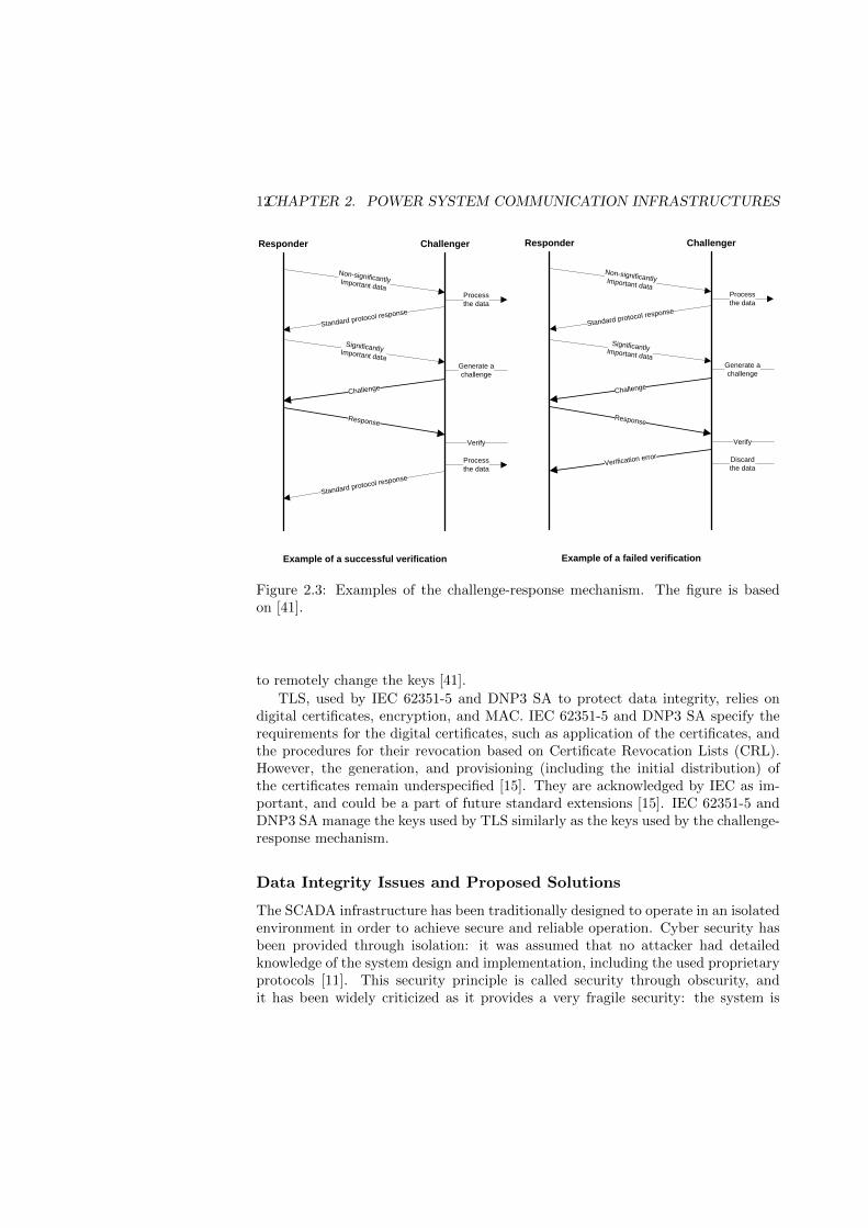
The challenge-response mechanism, used by IEC 62351-5 and DNP3 SA, isapplied at the application layer, assuming that the underlying layers do not provideany security. The main motivation behind this approach is that it permits that somedata exchange can be left unprotected, if desired, which reduces bandwidth andprocessing requirements [41]. Moreover, it is more practicals in diverse networksfound in power systems. The challenge-response mechanism can be described asfollows [41]. Upon receiving a message, the recipient (challenger) decides whetherthe data in the message are of significant importance, i.e., if the data should beprotected. If not, the message is processed without any verification. However,if the data should be protected, the challenger initiates the verification of dataintegrity by sending a challenge message to the sender (responder). The challengemessage contains information about the MAC algorithm that the responder shoulduse in the reply, and some randomly generated number to be send back in thereply (used as a protection against replay attacks). The challenge message alsospecifies if the data from the received message should be contained in the reply:if not, the challenger only verifies the identity of responder, if yes, the challengeralso verifies the data. The responder generates the reply message that includes theresponder identification, the randomly generated number sent by the challenger,and, if requested, the data to be verified. Before sending the reply message, theresponder performs the specified MAC algorithm on the message using a pre-sharedsession key, and adds the resulting MAC value to the reply message. Upon receivingthe reply, the challenger performs the same MAC algorithm, and if the resultingMAC values match, the verification of the data integrity is successful. Examples ofthe challenge-response mechanism are shown in Figure 2.3.
The MAC algorithms that can be used for the challenge-response mechanismare specified in IEC 62351-5 and DNP3 SA. The keys for the MAC algorithms arepre-shared by default. However, the need for more sophisticated managing of thekeys is recognized by IEC and the DNP User Group, and is a subject of futurestandard releases. Some recent releases, e.g., DNP SA version 5, provide methods
12CHAPTER 2. POWER SYSTEM COMMUNICATION INFRASTRUCTURES
Responder Challenger
Non-significantlyImportant data
Standard protocol response
Process
the data
SignificantlyImportant data
Challenge
Response
Process
the data
Generate a
challenge
Verify
Standard protocol response
Example of a successful verification
Responder Challenger
Non-significantlyImportant data
Standard protocol response
Process
the data
SignificantlyImportant data
Challenge
Response
Discard
the data
Generate a
challenge
Verify
Example of a failed verification
Verification error
Figure 2.3: Examples of the challenge-response mechanism. The figure is basedon [41].
to remotely change the keys [41].
TLS, used by IEC 62351-5 and DNP3 SA to protect data integrity, relies ondigital certificates, encryption, and MAC. IEC 62351-5 and DNP3 SA specify therequirements for the digital certificates, such as application of the certificates, andthe procedures for their revocation based on Certificate Revocation Lists (CRL).However, the generation, and provisioning (including the initial distribution) ofthe certificates remain underspecified [15]. They are acknowledged by IEC as im-portant, and could be a part of future standard extensions [15]. IEC 62351-5 andDNP3 SA manage the keys used by TLS similarly as the keys used by the challenge-response mechanism.
Data Integrity Issues and Proposed Solutions
The SCADA infrastructure has been traditionally designed to operate in an isolatedenvironment in order to achieve secure and reliable operation. Cyber security hasbeen provided through isolation: it was assumed that no attacker had detailedknowledge of the system design and implementation, including the used proprietaryprotocols [11]. This security principle is called security through obscurity, andit has been widely criticized as it provides a very fragile security: the system is

2.1. SCADA COMMUNICATION 13
secure as long as the details remain secret, but quickly breaks once the detailsare released [36]. Moreover, SCADA infrastructures are becoming more and moreintegrated with the other corporate infrastructures, and components and protocolshave been standardized and are available to practically anyone. This may leave theSCADA systems vulnerable to cyber attacks [11].
A cyber attack on the SCADA communication infrastructure may result inmanipulation of the data exchanged between RTUs and the SCADA server. Sincethe most commonly used protocols (IEC 101, IEC 104 over TCP/IP, and DNP3) canprovide only the detection of random bit errors and no protection of data integrity,the attack could remain undetected if the checksums are recalculated after themodification. The attack could result in intentionally wrong control signals andmodified (incorrect) measurements, and it could significantly disturb the powersystem applications that rely on these signals and measurements.
In order to protect the SCADA system against the data integrity attacks onthe messages exchanged between RTUs and the SCADA server, the communicationneeds to be cryptographically protected. Cryptographic protection can be providedby encapsulating (or tunneling) the protocols (IEC 101, IEC 104, and DNP3) into aprotocol that provides the cryptographic protection [11], e.g., IPsec [26] or TLS [9],or by using the recent protocol extensions that provide message authentication:IEC 62351-5 [24] and DNP3 SAv5 [1]. The cryptographic protection requires anupgrade of all RTUs in the system so they can support the computationally in-tensive cryptographic operations, and the key management. Some RTUs could bereprogrammed, while other legacy RTUs, that do not have sufficient processingpower, would need to be replaced or supplemented by bump-in-the-wire (BITW)devices [42]. The BITW devices are positioned next to legacy RTUs and tunnelsthe communication between the RTUs and the SCADA server. The communica-tion between BITWs and SCADA servers is protected while the communicationbetween BITWs and RTUs remains vulnerable. Due to the size of power systems,it may be practically and economically unfeasible to perform the upgrades in ashort amount of time, and therefore, it is expected to go in stages. In every stageof the upgrade, it is challenging to evaluate the system security and to optimallyselect RTUs that will maximally improve the security by upgrading. On the otherhand, the complexity of key management increases with the number of upgradedRTUs. Therefore, it is important to keep the number of upgraded RTUs low whileachieving a desirable level of system security.
In this thesis, we propose a framework that captures the characteristics of theSCADA communication infrastructure, and that can help in evaluating and improv-ing the system security. Furthermore, the framework can be used in every stage ofthe upgrade to prioritize the RTUs to be protected. The framework is described inPaper A, where we also use the framework to evaluate and to improve the securityof power systems considering the power system state estimation. Our results showthat the power system state estimation could be secured by upgrading only a subsetof all RTUs in the system.
14CHAPTER 2. POWER SYSTEM COMMUNICATION INFRASTRUCTURES
2.2 Inter-Control Center Communication
Modern power systems have become increasingly inter-connected in order to im-prove operational efficiency, e.g., the Western Interconnect (WECC) in the U.S.and the ENTSO-E in Europe. The proper operation of an inter-connected systemdepends on proper operation of its constituent control regions. Therefore, neigh-boring control regions need to exchange some information about their systems inreal-time, so that they can detect disturbances and quickly restore the system to asecure state in case of outages [44]. The exchange of real-time data between controlcenters is expected to be even more frequent in future power systems [44].
Historically, power system operators relied on proprietary protocols for inter-control center communication. However, with the increasing interconnectivity be-tween independent operators, the inability of proprietary protocols to provide in-teroperability has become a problem. To address the problem, the power industryjointly developed an international IEC 60870-6 standard based on the OSI model,and submitted it to the IEC for standardization [44]. IEC 60870-6 is a part of theIEC 60870, and it defines protocols for data exchange between control centers overa WAN. There are two protocol versions used for the data exchange: Tele-controlApplication Service Element-1 (TASE.1) and TASE.2. One of the differences be-tween the two versions is in the specification of mechanisms for message controland interpretation. TASE.2 specifies uses the Manufacturing Message Specifica-tion (MMS) for the specification, and it appears to be the prevalent version used.TASE.2 is usually referred to as the Inter-control Center Communication Protocol(ICCP) [38].
ICCP (IEC 60870-6/TASE.2)
ICCP specifies only the application layer of the OSI model, and it relies on otherprotocols for the underlying layers. ICCP specifies the use of MMS for the messagecontrol and interpretation, and it specifies the data object formats and the methodsfor data request and reporting. ICCP also specifies how the data can be sharedamong applications at different control centers.
ICCP is realized through logical connections, called associations. A controlcenter may establish associations with more than one control center. Moreover, itmay establish more than one association with the same control center that couldbe used to separate data transfers by priority.
ICCP defines data access control through bilateral tables. Bilateral tables spec-ify for every association which data elements can be accessed. However, ICCP doesnot provide any security of the data during transport.
Secure ICCP
Since ICCP does not protect the data during transport, IEC Technical Committee57 specified in the standards IEC 62351-3 [21] and IEC 62351-4 [22] how lower
2.2. INTER-CONTROL CENTER COMMUNICATION 15
layer protocols can protect the data. IEC 62351-3 specifies security measures forend-to-end security for protocols that go over TCP/IP. In particular, it describesthe parameters and settings for the Transport Layer Security (TLS) protocol [10]that should be configured by the operators. It also considers IPsec [26], but TLSis preferred [21]. IEC 62351-4 specifies security measures for protocols that useMMS, and provides the application layer security: prevents unauthorized access toinformation through authentication [22]. The authentication is achieved throughthe use of TLS.
Applied together, IEC 62351-3 and IEC 62351-4 protect the data integrity andconfidentiality while transported over ICCP, thanks to TLS. However, TLS doesnot protect against denial-of-service attacks, and such protection should be appliedthrough implementation-specific measures [21, 22].
The end-to-end security provided by IEC 62351-3 and IEC 62351-4 protectsICCP data transfer between two ICCP hosts, one per control center. These hosts,including databases that contain the data shared over ICCP, should be separatedfrom the Master Local Area Network (LAN), where all critical applications (e.g.,SCADA server and EMS) coexist [33]. ICCP hosts should be in a LAN which isseparated by a firewall from the Master LAN on one side, and on the other sideseparated by another firewall from the WAN used to transfer the ICCP data, asshown in Figure 2.4 (based on [33]). Such separation is a common security practicewhen some network services should be accessible from outside of the network butconnections or hosts cannot be fully trusted. The separated segment of the networkthat contains the services accessible from outside, is commonly referred to as thedemilitarized zone (DMZ). In case of the ICCP, the lack of trust typically comesfrom the fact that the WAN may be insecure [33].
Data Integrity and Availability Issues and Proposed Solutions
By following the standards IEC 62351-3 and IEC 62351-4, the integrity of ICCPdata can be protected when transfered between two ICCP hosts in DMZs. However,the ICCP data integrity may not be always protected, and IEC 62351-3 and IEC62351-4 may not always provide high communication availability, as explained inthe following.
First, within a ICCP host, the ICCP data might be unprotected after the TLSprotection is removed and before the data is stored in a database (and the other wayaround), which leaves a potential security threat. Moreover, the threat is aggravatedby the fact that the ICCP hosts are in DMZs. They could be victims of sophisticatedtargeted trojans, whose goal is to manipulate the ICCP data. Examples of recentsophisticated targeted trojans that were targeting industrial control systems areStuxnet and Duqu [39]. The manipulation of ICCP data could significantly disturbthe power system applications that rely on the data exchanged by the ICCP.
Second, TLS provides data integrity and confidentiality of the transmitted data,but it does not protect against denial of service attacks [21, 22]. An attacker thatobtains access to the WAN may identify some critical low latency data exchange by

16CHAPTER 2. POWER SYSTEM COMMUNICATION INFRASTRUCTURES
ICCP host
SCADA WAN
SCADA server EMS
DMZ
Master LAN
Control Center A
ICCP host
SCADA WAN
SCADA server EMS
DMZ
Master LAN
Control Center BWANICCP traffic ICCP traffic
Figure 2.4: Inter-control center communications. The figure is based on [33].
observing the size, and sender and receiver addresses of every message, and it mayperform a targeted denial-of-service attack against such data exchange. Such anattack might be misinterpreted as packet loss due to a congestion, and therefore beundetected. As a consequence, the attack may disturb power system applicationsthat rely on timely delivery of exchanged data.
In this thesis, we address both issues. First, in Paper B, we study how an at-tack against the integrity of ICCP data can affect the fully distributed multi-areapower system state estimation, which requires timely data exchange between controlcenters of neighboring regions. We define attack strategies for sophisticated manip-ulation of the exchanged data and show that they can disable the state estimation.However, we also show a possible way to detect and to mitigate such attacks. Sec-ond, in Paper C, we study how anonymity networks could be used to improve thedata availability if face of targeted denial-of-service attacks. Anonymity networksdisguise the sender and the receiver of every message through message relaying,which increases the communication overhead and delay. However, the delay maybe a concern for some power system applications, such as distributed state estima-tion. Therefore, we analyze how much the availability can be improved for a givendelay. We quantify the availability by the provided anonymity, i.e., the difficultyof the attacker to correctly identify the origin and the destination of the data. Wequantify the delay by the number of times the data are relayed. Our results showthat, surprisingly, the availability does not always get improved with additionaldelay. Moreover, we show that it is better to overestimate than to underestimatethe attacker’s capabilities when designing anonymity networks.
Chapter 3
Power System State Estimation
Power system state estimator obtains an estimate of the state of the system byprocessing redundant measurements [2, 34]. Besides the measurements, the stateestimator uses a model of the transmission network as input.
The state estimation can be centralized (single-area) or distributed (multi-area).The single-area state estimation obtains the estimate of an entire power system, ora single-area power system, performed by a single computing entity. An example ofthe single-area state estimation is the state estimation of a power system controlledby an independent power system operator, where the estimation is performed in theoperator’s control center. The multi-area state estimation obtains the estimate of apower system that consists of multiple interconnected areas, where the estimationof each area is performed by an independent computing entity. To obtain a consis-tent state estimate of the entire multi-area power system, the computing entitiesneed to cooperate and exchange some data used as input to the state estimatorin every computing entity. An example of the multi-area state estimation is thestate estimation of an interconnected power system that consists of a multiple areascontrolled by independent operators. The state estimation of an area is performedin the control center of the operator that controls the area.
3.1 Transmission Network Model
We consider a transmission network that consists of buses that are interconnectedby branches. The term bus is derived from the Latin omnibus, which means ”forall”, and it is a bar of metal to which all incoming and outgoing conductors, i.e.,wires through which the electric current can flow, are connected [43]. Branchesinclude transmission lines, transformers and phase shifters [2].
The admittance matrix Y of the entire transmission network can be built fromscratch by introducing one-by-one components (their models) of the system, andupdating the corresponding entries in Y [2]. The components include transmissionlines, loads, generators, transformers, shunt capacitors and reactors. The matrix Y
17
18 CHAPTER 3. POWER SYSTEM STATE ESTIMATION
is complex in general, and can be written as G + jB, where G is the conductancematrix and B is susceptance matrix. For more information about the componentsand their models, and how the matrix Y is built, we refer to [2].
A transmission network model can be built by deriving a set of nodal equationsby using the Kirchhoff’s current law at every bus in the transmission network [2, 34].Let us denote the vector of bus voltage phasors by V, and the vector of bus currentinjections by I. Then, in a network of n buses, the nodal equations can be expressedwith the following matrix equation,
I = Y ·V;
I1I2...In
=
y11 y12 ... y1ny21 y22 ... y2n... ... ... ...yn1 yn2 ... ynn
·V1V2...Vn
. (3.1)
Power injections at any bus can be derived by multiplying the vector V withthe conjugate of the vector I from (3.1) [43]. Active and reactive power injectionscan be further derived by considering the real and the imaginary part of equationV · I∗. The active power injection Pbi and reactive power injection Qbi at bus bican expressed as
Pbi = Vbi∑
bj∈N (bi)
Vbj (gijcos(θij) + bijsin(θij)),
Qbi = Vbi∑
bj∈N (bi)
Vbj (gijsin(θij)− bijcos(θij)),(3.2)
where Vbi is the voltage amplitude at bus bi, θij is the difference of phase anglesbetween bus bi and bus bj , gij and bij are the corresponding entries in matrices Gand B, respectively, and N (bi) is the set of adjacent buses to bus bi [2, 43].
Power flows from bus bi to bus bj can be derived similarly to (3.2), and expressedas
Pbibj = V 2bi(gsi + gij)− VbiVbj (gijcos(θij) + bijsin(θij)),
Qbibj = −V 2bi(bsi + bij)− VbiVbj (gijsin(θij)− bijcos(θij)),
(3.3)
where gsi + jbsi is the admittance of the shunt branch connected at bus bi [2].
3.2 Measurement Model
Based on (3.2) and (3.3), all current and power injections or flows can be deter-mined once we know the voltage phasors. However, we can use the same model tocompute the voltage phasors based on the measurements. The most commonly usedmeasurements are power flows, power injections, bus voltage magnitudes and cur-rent flow magnitudes [2]. Unfortunately, we cannot just directly use the measuredvalues in (3.2) and (3.3) to get the voltage phasors. The measurements are proneto errors, and typically not all flows and injections are measured in the system.

3.3. SINGLE-AREA STATE ESTIMATION 19
Therefore, we need to estimate the voltage phasors based on the obtained mea-surements. In order to perform the estimation, we need a model of measurements,which is described as follows.
Let us consider the set of M measurements that are given by the vector
Z =
z1z2...zM
=
fz1(x)fz2(x)...
fzM (x)
+
ez1ez2...ezM
= F (x) + e, (3.4)
where x is the state vector constructed from the vector V by considering the phaseangles and the voltage amplitudes separately, fzi(x) is a function relating measure-ment zi to the state vector x, and e is the vector of measurement errors. If themeasurement zi is an injection or a flow, then the function fzi(x) can be expressedbased on (3.1), (3.2), or (3.3). However, if the measurement zi is a voltage ampli-tude or a phase angle, then the function fzi(x) equals to the corresponding entry inthe vector x. Measurement errors are typically assumed to be independent randomnoise with Gaussian distribution of zero mean, and consequently the covariancematrix W = E(eeT ) is diagonal [2, 34, 43].
3.3 Single-area State Estimation
In the case of single-area state estimation, all the measurements and the entiretransmission network model are passed to a computing entity that performs thestate estimation.
Maximum Likelihood Estimation
Maximum Likelihood Estimation (MLE), a method widely used in statistics, can beused to determine the most likely state of the system based on the measurements.The measurement errors are assumed to have a known probability distribution, butwith unknown parameters. Let us denote by l(zi) the probability density functionwhich represents the probability of measuring zi. Assuming that the measurementerrors are independent, we can express the joint probability density function of allmeasurements as the product of individual probability density functions [2]
lM (Z) = l(z1)l(z2) · · · l(zM ). (3.5)
The function lM (Z) is referred to as the likelihood function, and it represents theprobability of measuring the measurements in Z. It will obtain its peak valuewhen the unknown parameters are chosen to be the closest to the actual values [2].Therefore, by maximizing (3.5) we will reach the maximum likelihood estimatesfor the parameters of interest. Typically, the measurement error probability dis-tributions are assumed to be Gaussian distributions, as described in Section 3.2.In that case, the parameters of interest are the mean values and the variances. In

20 CHAPTER 3. POWER SYSTEM STATE ESTIMATION
order to simplify the maximization problem, the likelihood function is replaced byits logarithm, so called the Log-Likelihood function, and it can be expressed as
L = log(lM (Z)) =
M∑i=1
log(l(zi)) = −1
2
M∑i=1
(zi − E(zi)
σi)2 − M
2log(2π)−
M∑i=1
log(σi),
(3.6)where the measurement error probability distributions are assumed to be Gaussiandistributions with the mean value E(zi) and standard deviation σi for the measure-ment zi [2]. The expected value E(zi) can be expressed as fzi(x), and σi is assumedto be known (it equals to the square root of diagonal entry wii of the covariancematrix W) [2]. Finally, the MLE problem can be defined as
maxx
log(lM (Z)), (3.7)
which is equivalent to
J(x) = minx
M∑i=1
(zi − E(zi)
wii)2 = min
x[Z− F (x)]TW−1[Z− F (x)]. (3.8)
Weighted Least Squares Estimator (WLSE)
The optimization problem (3.8) can be solved by using the weighted least squaresestimator (WLSE), which can be formulated as follows. At the minimum of (3.8),the first-order optimality conditions have to be satisfied:
g(x) =∂J(x)
∂x= −HT (x)W−1[Z− F (x)] = 0, (3.9)
where H = [∂F (x)/∂x] is the Jacobian of F (x) [2]. By expanding the function g(x)into its Taylor series around x(k), where k is the iteration index, and by consideringthe first two terms of the series we yield an iterative scheme,
x(k+1) = x(k) + [HT (x(k))W−1H(x(k))](−1)HT (x)W−1[Z− F (x)], (3.10)
known as the Gauss-Newton method [2]. Therefore, at each iteration k, the updatevector ∆x(k) = x(k+1) − x(k) can be calculated by solving the set of equations
∆x(k) = [HT (x(k))W−1H(x(k))](−1)HT (x)W−1[Z− F (x)], (3.11)
also known as the Normal Equations.WLSE includes the iterative solution to (3.11) and it can be outlined as follows.
1. Set k = 0, and assume the starting vector x(0).
2. Calculate the update vector ∆x(k) using (3.11).
3. If |∆x(k)|∞ 6≤ ε, update x(k+1) = x(k)+∆x(k) and k = k+1, and go to Step 2.Else, stop the estimation: the estimator found the solution vector k∗ = x(k),after k∗ = k iterations (convergence time). ε is the convergence threshold and| · |∞ denotes the maximum norm of a vector.

3.3. SINGLE-AREA STATE ESTIMATION 21
Bad Data Detection (BDD)
Large measurement errors may cause the state estimator to find an incorrect so-lution (a state vector that is far from the actual one), and therefore, should bedetected, identified, and to eliminated. Such errors may occur when the metershave bias, drift, and wrong physical connections [2]. Some of the errors are obvi-ous, e.g., negative voltage amplitudes, and can be detected and eliminated a-prioristate estimation. Unfortunately, some other errors may not be so easily detectable,and therefore the state estimator needs to be complemented with features that areable to detect and identify any type of bad data. These features depend on thestate estimation method, and are referred to as Bad Data Detection (BDD) [2].
After the WLSE obtains a solution, the BDD is done by processing the resultingmeasurement residuals, i.e., ∆Z(k∗) = Z− F (x∗). The most commonly used BDDalgorithm is the Largest Normalized Residual Test (LNRT) [2, 34]. LNRT identifiesthe largest element in the normalized residual vector (∆Z(k∗)/||∆Z(k∗)||2), and ifthat element is larger than a statistical threshold, then the corresponding measure-ment as assumed as bad data. The threshold can be chosen based on the desireddetection sensitivity. After the bad data is identified, the measurement is discardedand the WLSE is started again.
Data Integrity Issues and Proposed Solutions
Measurements used as input to the WLSE are provided by the SCADA infrastruc-ture. The integrity of measurements in face of bit errors is typically provided by anerror detection code, e.g., cyclic redundancy check or a cryptographic has function,calculated at the RTUs, which is sent along with the data. All communicationprotocols used for the communication with RTUs implement such error detection,as described in Chapter 2, Section 2.1. However, the integrity of measurements inface of malicious manipulation of the data may not been provided (Section 2.1),which leaves the measurements vulnerable to cyber attacks [16].
An attacker that gains access to the SCADA infrastructure could manipulatethe measurements sent from the RTUs to the control center. The BDD is supposedto detect inconsistent measurements, but it turns out that the measurements couldbe manipulated in a such way so that the BDD does not detect it [4, 8, 32]. Suchmanipulations are usually referred to as stealth attacks on the state estimator.
The manipulation of measurements can be described by an attack vector a addedto the actual measurement vector Z, i.e.,
Za = Z + a, (3.12)
where Za denotes the measurements after the manipulation. If the attack vectorsatisfies
a = Hc, for some c ∈ Rn, (3.13)

22 CHAPTER 3. POWER SYSTEM STATE ESTIMATION
then BDD will not detect the manipulation, and the vector a is a stealth attack.Hence, if an attacker wants to change a particular measurement zi, it might haveto change several other measurements to avoid the BDD.
The difficulty of performing stealth attacks against some measurements has beeninvestigated in [32, 4, 40, 29, 8, 27]. However, a common assumption was that themeasurements are delivered directly to the control center, ignoring the actual com-munication network topology. The characteristics of the SCADA communicationinfrastructure were considered in [8], where the authors assumed that the measure-ments are first multiplexed in the substations, and then send directly to the controlcenter. However, often the measurements visit other substations before they getdelivered to the control center due to the topology of SCADA wide area network,described in Section 2.1.
In this thesis, we propose a framework that captures the power system char-acteristics and the characteristics of the SCADA communication infrastructure inorder to estimate the vulnerability of a given system to stealth attacks, and tounderstand how the stealth attacks can be mitigated using various mitigationsschemes. In Paper A, we develop quantitative metrics to assess the importanceof substations and communication equipment with the respect to stealth attacksagainst the state estimation. We use the metrics to evaluate the potential of variousmitigations schemes, such as single-path routing, multi-path routing, and data au-thentication. We consider the data authentication achieved either by encapsulating(or tunneling) the communication through bump-in-the-wire (BITW) devices adja-cent to legacy RTUs [42], or by replacing the legacy RTUs with modern RTUs thatsupport message authentication and secure extensions of SCADA/RTU communi-cation protocols (Section 2.1). SCADA system designers and operators can use theframework to evaluate the vulnerability of their systems to the stealth attacks, andto evaluate the efficiency of different mitigation schemes to protect their systemsagainst the attacks.
3.4 Multi-area State Estimation
In the case of multi-area state estimation, the power system consists of a numberof areas and the state estimation of each area is performed by an independentcomputing entity. Each entity receives only a subset of all measurements and thepart of the transmission network model that correspond to its area. Areas canshare buses and transmission lines, so the entities need to coordinate to obtain aconsistent state estimate.
There have been many proposed algorithms for multi-area state estimation,e.g., [7, 28, 14, 12, 13, 37, 5, 31, 38, 25]. Typically, the algorithms use the normalequations (3.11), or their modifications, to perform updates within the areas beforethe coordination [7, 28, 12, 13, 37, 5, 31, 38, 25]. The algorithms can be categorizedbased on a number of criteria [18]. First, they may differ in the way the coordinationis done: in a hierarchical manner, e.g., in [7, 28, 14, 12, 13], or in a distributed

3.4. MULTI-AREA STATE ESTIMATION 23
manner, e.g., in [37, 5, 31, 38, 25]. Second, they may differ in terms of the timewhen the coordination is done with the respect to the iterations of the areas’ localstate estimators. The coordination can be done after each iteration, e.g., in [28, 14,5, 31, 38, 25], or after a number of iterations, e.g., in [7, 12, 13]. Third, they maydiffer in the assumption on the shared buses and transmission lines between areas.Some assume that areas share only transmission lines [28, 14, 13, 5, 38, 25], whileothers that the areas share only buses [7, 12, 37, 31], or both transmission lines andbuses. For a detailed overview of multi-area state estimation algorithms and theircategorization, we refer to [18].
Hierarchical Multi-Area State Estimation
In a hierarchical architecture, there exists a central unit that supervises the entities,and subsequently, coordinates the estimates performed by the entities. The entitiescommunicate only with the central unit. The estimation can be considered as a twostep process. In the first step, areas perform independent local calculations usingtheir best knowledge of the state estimates of the other areas. In the second step,the central processor coordinates the solutions obtained by areas until a consistentstate estimate is found. The steps may be cyclically repeated a number of timesbefore a solution is found.
Fully Distributed Multi-Area State Estimation
In a fully distributed architecture, the areas directly communicate among each otherin order to obtain a consistent state estimate. The estimation can be considered as atwo step process, similarly to the hierarchical architecture. The only difference is inthe second step: the areas coordinate among themselves. They exchange their mostrecent estimates of the state variables that correspond to the shared buses [38, 25].The exchanged values are later used when the first step is repeated [38, 25]. Theexchange may be synchronous, in which case the steps are synchronized amongthe areas, or asynchronous [38]. In the asynchronous case, it might be hard toguarantee that a solution will be found [38].
Data Integrity Issues and Proposed Solutions
It is expected that the integrity of the data exchanged between the computingentities is protected. However, in the case of an interconnected power system op-erated by independent system operators, the integrity of data exchanged betweenthe operators may get violated, as described in Chapter 2, Section 2.2.
In this thesis, in Paper B, we study how a violation of the integrity of dataexchanged between independent computing entities can effect the fully distributedmulti-area state estimation. We consider an attacker that compromises a singlecomputing entity and manipulates with the date sent from and to the entity. Wedefine various attack strategies that differ in the attacker’s knowledge of the system.

24 CHAPTER 3. POWER SYSTEM STATE ESTIMATION
We show that the attack strategies can significantly disturb the state estimation:they can prevent the state estimator to find a solution, or they can lead the stateestimator to an erroneous solution. Moreover, our results emphasize the importanceof protecting the confidentiality of the measurements: the attacker can performsignificantly stronger attacks if it knows the measurements. We also show a possibleway to detect the convergence problems, e.g., caused by the attacks, and a simplemitigation scheme.
Chapter 4
Summary of original work
Paper A: Network-aware Mitigation of Data IntegrityAttacks on Power System State Estimation
Ognjen Vukovic, Kin Cheong Sou, Gyorgy Dan, Henrik Sandberg. InIEEE Journal on Selected Areas in Communications (JSAC), vol. 30, no.6, July 2012.
Summary: In this paper we investigate the vulnerability of single-area powersystem state estimation to attacks performed against the communication infras-tructure used to collect measurement data from the substations. We propose aframework that captures the power system characteristics and the SCADA com-munication infrastructure, and define security metrics that quantify the importanceof individual substations and the cost of attacking individual measurements. Wealso propose approximations of these metrics, that are based on the communica-tion network topology only, and we compare them to the exact metrics. We provideefficient algorithms to calculate the security metrics. We use the metrics to showhow various network layer and application layer mitigation strategies, like singleand multi-path routing and data authentication, can be used to decrease the vul-nerability of the state estimation. We illustrate the efficiency of the algorithms onthe IEEE 118 and 300 bus benchmark power systems.
Contribution: The author of this thesis developed the framework in collabo-ration with the third co-author, defined the metrics, implemented and carried outthe simulations, and analyzed the resulting data. The article was written in collab-oration with the third co-author. The second and the forth co-authors developedthe efficient algorithms to calculate the security metrics.
25

26 CHAPTER 4. SUMMARY OF ORIGINAL WORK
Paper B: On the Security of Distributed Power System StateEstimation under Targeted Attacks
Ognjen Vukovic and Gyorgy Dan. In Proc. of ACM Symposium onApplied Computing (SAC), Mar. 2013.
Summary: In this paper we investigate the vulnerability of fully distributedmulti-area power system state estimation to attacks against data exchange betweenindependent computing entities, e.g., control centers of an interconnected powersystem. We consider an attacker that compromises a single control center and ma-nipulates the data exchanged between the control center and its neighbors. Wedescribe five attack strategies, and evaluate their impact on the IEEE 118 bench-mark power system. We show that even if the state estimation converges despitethe attack, the estimate can have up to 30% of error, and bad data detection cannotlocate the attack. We also show that if powerful enough, the attack can impedethe convergence of the state estimation, and thus it can blind the system operators.Our results show that it is important to provide confidentiality for the measurementdata in order to prevent the most powerful attacks. Finally, we discuss a possibleway to detect and to mitigate these attacks.
Contribution: The author of this thesis defined the attack strategies andthe detection method in collaboration with the second co-author, implemented andcarried out the simulations, and analyzed the resulting data. The article was writtenin collaboration with the second co-author.
Paper C: Traffic Analysis Attacks in Anonymity Networks:Relationship Anonymity-Overhead Trade-off
Ognjen Vukovic, Gyorgy Dan, and Gunnar Karlsson. Technical Report,KTH, TRITA-EE 2013:007, February 2013.
Summary: In this paper we study how anonymity networks can be used toimprove data availability in face of targeted denial-of-service attacks. Anonymitynetworks conceal the sender and the receiver of every message, i.e., provide relation-ship anonymity, through message relaying. Higher relationship anonymity impliesthat it is harder for an attacker to identify the sender and the receiver of a message,and therefore, harder for the attacker to perform targeted denial-of-service attacks.However, provided relationship anonymity comes at the price of increased commu-nication overhead and delay due to the message relaying. Since some applications,e.g., fully distributed multi-area power system state estimation, require timely datadelivery, in this work we investigate how to optimize the relationship anonymityfor a given overhead and delay. We use two anonymity networks: MCrowds, an ex-tension of Crowds, which provides unbounded communication delay and Minstrels,which provides bounded communication delay. We derive exact and approximateanalytical expressions for the relationship anonymity for these networks. Using
27
MCrowds and Minstrels we show that, contrary to intuition, increased overheaddoes not always improve anonymity. We investigate the sensitivity of provided re-lationship anonymity to the mis-estimation of the attacker’s capabilities, and showthat it is better to overestimate than to underestimate the attacker’s capabilitieswhen configuring anonymity networks.
Contribution: The author of this thesis defined the two anonymity networks incollaboration with the second co-author, derived the analytical expressions for therelationship anonymity for these networks, implemented and carried out the simu-lations, and analyzed the resulting data. The article was written in collaborationwith the second co-author. The work was supervised by the third co-author.
Publications not included in the thesis:
• Ognjen Vukovic, Gyorgy Dan, and Gunnar Karlsson, “On the Trade-off be-tween Relationship Anonymity and Communication Overhead in AnonymityNetworks”, in Proc. of IEEE International Conference on Communications(ICC), Jun 2011.
• Ognjen Vukovic, Kin Cheong Sou, Gyorgy Dan, and Henrik Sandberg, “Network-layer Protection Schemes against Stealth Attacks on State Estimators inPower Systems”, in Proc. of IEEE SmartGridComm, Oct. 2011.
• Gyorgy Dan and Ognjen Vukovic, “Utility-based PMU Data Rate Alloca-tion under End-to-end Delay Constraints”, IEEE COMSOC MMTC E-Letter,vol.7, no.8, November 2012.


Chapter 5
Conclusions and Future work
This thesis addresses data integrity and availability issues in power system commu-nication infrastructures. In the following, we summarize the main contributions ofthis thesis, and we outline some possible directions for future work.
We developed a framework and proposed security metrics that can be used toevaluate the security of a power system against stealthy attacks on measurements.We provided algorithms to calculate the metrics, and proposed approximations ofthe metrics, that only consider the communication topology, and therefore, areeasier to calculate. We provided an algorithm that could be used to improve thesecurity of the system by applying simpler mitigation strategies, e.g., rerouting, ormore involved mitigation strategies, such as multi-path routing and cryptographicprotection. Our results emphasized the importance of considering both the com-munication infrastructure and the power system applications, particularly powersystem state estimation, when analyzing and improving the security of the system.
We investigated the vulnerability of fully distributed multi-area state estimation(described in Section 3.4) to attacks against the integrity of data exchanged betweenindependent computing entities. We described five attack strategies for sophisti-cated manipulation of the exchanged data, that differ in the attacker’s knowledgeof the system. We showed that the attacks can result in high estimation errors, ordisable the state estimation by preventing it from finding a solution. Moreover, ourresults emphasize the importance of protecting the confidentiality of measurementsused for the state estimation, since the attacker can perform more effective attacksby knowing the measurements. We also proposed a detection scheme that coulddetect such attacks. The detection scheme relies on properties of the algorithmused for the state estimation to detect convergence problems. Based on this detec-tion scheme, we proposed a simple mitigation scheme: upon detecting an attack,the independent entities perform isolated state estimation (without exchanging anydata).
Finally, we studied how data availability in power system communication in-frastructures could be improved by anonymity networks. Since anonymity net-
29

30 CHAPTER 5. CONCLUSIONS AND FUTURE WORK
works increase message delay, which could be an issue for power system applica-tions that require timely message delivery, we studied the trade-off between theprovided anonymity and the message delay. We found that, contrary to intuition,the anonymity is not always improved with more delay. Moreover, we show thatit is better to overestimate than to underestimate the attacker’s capabilities whenconfiguring an anonymity network.
Future Work
There are a number of different possibilities for future work. Some of them arecomplement studies to the studies included in this thesis, while other studies couldaddress some aspects of data integrity and availability in power system communica-tion infrastructures not covered in this thesis. We outline some of the possibilitiesas follows.
Data integrity
We developed a framework and security metrics that evaluate the security of thepower system state estimation against attacks on the data integrity of RTU toSCADA server communication. A complement study could analyze the robust-ness of the metrics to changes in the power system transmission network topol-ogy, as well as to random errors. Moreover, attacks on the data integrity of RTUto SCADA server communication could be also targeted against control messagesused to remotely operate control relays. Similar security metrics, and a frameworkthat includes the same model of communication infrastructure complemented witha model of the physical system could be developed to consider such attacks.
We investigated how attacks on data integrity of ICCP data could affect thefully distributed multi-area state estimation. We proposed a detection scheme thatcould detect such attacks, and outlined a simple mitigation scheme. However, thedetection scheme could be improved so that the attack can be localized. Suchlocalization could lead to an improved mitigation scheme. Moreover, attacks ondata integrity of ICCP data could be targeted against data used by other powersystem applications. An open question if such attacks could also disturb thoseapplications.
Data availability
We studied how anonymity networks could be used to improve the data availabilityagainst targeted DoS attacks, while keeping message delay low. Studies on howtargeted DoS attacks could affect power system applications that require timelydata delivery, such as fully distributed multi-area state estimation, could help infinding a good balance between the improved data availability and the increaseddelay.

31
Furthermore, a subject of future work could be to address the data availabilityin communication networks used for the acquisition of PMU measurements. Thefrequency at which a PMU takes and delivers measurements is selectable, and itmay go up to 120Hz. A communication network that acquires measurements frommany PMUs at such frequency could experience congestion and losses. Therefore,it is important to understand how congestion could affect the PMU data delivery,and furthermore, to find schemes that would optimally control message generationrate for every PMU in the network so that the losses are minimized.


Bibliography
[1] IEEE Standard for Electric Power Systems Communications-Distributed Net-work Protocol (DNP3). IEEE Std 1815-2012 (Revision of IEEE Std 1815-2010), pages 1–821, 2012.
[2] A. Abur and A.G. Exposito. Power System State Estimation: Theory andImplementation. Marcel Dekker, Inc., 2004.
[3] D. Bailey and E. Wright. Practical SCADA for Industry. Newnes, 2003.
[4] R.B. Bobba, K.M. Rogers, Q. Wang, H. Khurana, K. Nahrstedt, and T.J. Over-bye. Detecting false data injection attacks on DC state estimation. In Preprintsof the First Workshop on Secure Control Systems, CPSWEEK, Stockholm,Sweden, April 2010.
[5] C.W. Brice and R.K. Cavin. Multiprocessor static state estimation. IEEETransactions on Power Apparatus Systems, pages 302–308, February 1982.
[6] G. Clarke and D. Reynders. Practical Modern SCADA Protocols: DNP3,60870.5 and Related Systems. Newnes, 2004.
[7] K.A. Clements, O.J. Denison, and R.J. Ringlee. A multi-area approach tostate estimation in power system networks. In IEEE PES Summer Meeting,July 1972.
[8] G. Dan and H. Sandberg. Stealth attacks and protection schemes for stateestimators in power systems. In Proc. of IEEE SmartGridComm, Oct. 2010.
[9] T. Dierks and C. Allen. The tls protocol version 1.0. RFC 2246, IETF, January1999. URL http://www.ietf.org/rfc/rfc2246.txt.
[10] T. Dierks and E. Rescorla. The Transport Layer Security (TLS)Protocol, Version 1.2. RFC 5246, IETF, August 2008. URLhttp://www.ietf.org/rfc/rfc5246.txt.
[11] D. Dzung, M. Naedele, T.P. Von Hoff, and M. Crevatin. Security for industrialcommunication systems. Proceedings of the IEEE, 93(6):1152–1177, 2005.
33

34 BIBLIOGRAPHY
[12] R. Ebrahimian and R. Baldick. State estimation distributed processing. IEEETrans. on Power Systems, 4:1240–1246, Nov. 2000.
[13] R. Ebrahimian and R. Baldick. Distributed state estimation for mega grids.In Proc. of the 15th PSCC Liege, pages 22–26, Aug. 2006.
[14] A.A. El-Keib, J. Nieplocha, H. Singh, and D.J. Maratukulam. A decom-posed state estimation technique suitable for parallel processor implementa-tion. IEEE Trans. on Power Systems, 3:1088–1097, Aug. 1992.
[15] S. Fries, H.J Hof, and M. Seewald. Enhancing IEC 62351 to improve securityfor energy automation in smart grid environments. In Proc. of the fifth Inter-national Conference on Internet and Web Applications and Services (ICIW),pages 135–142, 2010.
[16] A. Giani, S.S. Sastry, K.H. Johansson, and H. Sandberg. The VIKING project:An initiative on resilient control of power networks. In Proc. of the 2nd Inter-national Symposium on Resilient Control Systems, 2009.
[17] G. Gilchrist. Secure authentication for dnp3. In IEEE Power and EnergySociety General Meeting - Conversion and Delivery of Electrical Energy in the21st Century, pages 1–3, 2008.
[18] A. Gomez-Exposito, A. de la Villa Jaen, C. Gomez-Quiles, P. Rousseaux, andT. Van Cutsem. A taxonomy of multi-area state estimation methods. ElectricPower Systems Research, 81:1060–1069, 2011.
[19] University of Southern California Information Sciences Institute.Internet Protocol. RFC 791, IETF, September 1981. URLhttp://www.ietf.org/rfc/rfc791.txt.
[20] University of Southern California Information Sciences Institute. Trans-mission Control Protocol. RFC 793, IETF, September 1981. URLhttp://www.ietf.org/rfc/rfc793.txt.
[21] International Electro-technical Commission (IEC) Technical Committee 57.IEC62351 Power systems management and associated information exchange- Data and communications security - Part 3: Communication network andsystem security - Profiles including TCP/IP. Technical report, IEC TechnicalCommittee 57, Jun 2007.
[22] International Electro-technical Commission (IEC) Technical Committee 57.IEC62351 Power systems management and associated information exchange -Data and communications security - Part 4: Profiles including MMS. Technicalreport, IEC Technical Committee 57, Jun 2007.

BIBLIOGRAPHY 35
[23] International Electro-technical Commission (IEC) Technical Committee 57.IEC62351 Power systems management and associated information exchange- Data and communications security - Part 2: Glossary of terms. Technicalreport, IEC Technical Committee 57, August 2008.
[24] International Electro-technical Commission (IEC) Technical Committee 57.IEC62351 Power systems management and associated information exchange- Data and communications security - Part 5: Security for IEC 60870-5 andderivatives. Technical report, IEC Technical Committee 57, August 2009.
[25] V. Kekatos and G.B. Giannakis. Distributed robust power system state esti-mation, 2013.
[26] S. Kent and R. Atkinson. Security architecture for the internet protocol. RFC2401, IETF, November 1998. URL http://www.ietf.org/rfc/rfc2401.txt.
[27] T.T. Kim and H.V. Poor. Strategic protection against data injection attackson power grids. IEEE Trans. on Smart Grid, 2:326–333, Jun. 2011.
[28] H. Kobayashi, S. Narita, and M.S.A.A. Hamman. Model coordination methodapplied to power system control and estimation problems. In Proc. of theIFAC/IFIP 4th Int. Conf. on Digital Computer Appl. to Process Control, 1974.
[29] O. Kosut, L. Jia, R. Thomas, and L. Tong. Malicious data attacks on smartgrid state estimation: Attack strategies and countermeasures. In Proc. of IEEESmartGridComm, Oct. 2010.
[30] T.E. Dy Liacco. Real-time computer control of power systems. In Proc. ofIEEE, 62(7):884–891, July 1974.
[31] S.Y. Lin and C.H. Lin. An implementable distributed state estimator anddistributed bad data processing schemes for electric power systems. IEEETransactions on Power Systems, pages 1277–1284, August 1994.
[32] Y. Liu, P. Ning, and M. Reiter. False data injection attacks against stateestimation in electric power grids. In Proc. of the 16th ACM conference onComputer and Communications Security (CCS), pages 21–32, 2009.
[33] J.T. Michalski, A. Lanzone, J. Trent, and S. Smith. Secure ICCP Integra-tion Considerations and Recommendations. Technical report, Sandia NationalLaboratories, Jun 2007.
[34] A. Monticelli. Electric power system state estimation. Proc. of the IEEE, 88(2):262–282, 2000.
[35] D. Reynders, S. Mackay, and E. Wright. Practical Industrial Data Communi-cations. Newnes, 2005.

36 BIBLIOGRAPHY
[36] B. Schneier. Secret and Lies: Digital Security in a Networked World. WileyPublishing, Inc., January 2004.
[37] F.C. Schweppe, J. Wildes, and D.B. Rom. Power system static-state estima-tion, Part I, II, III. IEEE Transactions on Power Apparatus and Systems, 89:120–135, January 1970.
[38] M. Shahidehpour and Y. Wang. Communication and Control in Electric PowerSystems. John Wiley and Sons, Inc., 2003.
[39] Symantec Security Response. W32.duq: The precursor to the next stuxnet,November 2011.
[40] A. Teixeira, S. Amin, H. Sandberg, K.H. Johansson, and S.S. Sastry. Cyber-security analysis of state estimators in electric power systems. In Proc. ofIEEE Conf. on Decision and Control (CDC), Dec. 2010.
[41] The DNP User Group. DNP Secure Authentication v5. Technical report, TheDNP User Group, November 2011.
[42] P.P. Tsang and S.W. Smith. YASIR: A low-latency, high-integrity securityretrofit for legacy scada systems. In Proc. of IFIP/TC11 International Infor-mation Security Conference, 2008.
[43] A. von Meier. Electric Power Systems: A Conceptual Introduction. John Wileyand Sons, Inc., 2006.
[44] F.F. Wu, K. Moslehi, and A. Bose. Power System Control Centers: Past,Present, and Future. Proceedings of the IEEE, 93(11):1890–1908, 2005.