data organization and processing - univerzita...
TRANSCRIPT

Data Organization and Processing
(NDBI007)
David Hoksza
http://siret.ms.mff.cuni.cz/hoksza1

Course organization
Classes
• Once per two weeks
• Practicing algorithms learned in lectures
• Attendance obligatory• one absence allowed
• second absence can be compensated by an essay
Exam
• Written test (both practical and theoretical questions
2

Literature
• Lecture slides
• Pokorný, J., Žemlička, M.: Základy implementace souborů a databází, Praha, Karolinum 2004, ISBN 80-246-0837-5
• Research papers introducing the discussed algorithms
3

Scope of the course
• When dealing with large amount of data, classical in-memory data structures fail because they consider flat memory hierarchy
• Need for specialized data techniques and structures for data not present in the main memory• memory vs. storage → nanoseconds vs. milliseconds
• Focus on secondary memory, especially magnetic HDDs and SSDs
4

Memory models
• RAM model• Traditional model
• External memory model• Takes external memory into account
• Cache-oblivious model• Takes memory hierarchy into account
5

Random access memory (RAM) model
• Traditional model where the run time is based on the number of instructions with respect to the size of the input n
• Implicit assumptions• large enough main memory to store all the data
• memory allocation in unit time
6
CPU Memory

• Also known as I/O model or disk access model (DAM)
• Realizing the existence of memory hierarchy
• Counting the number of memory transfers between cache (infinitely fast) and disk (external memory)• Disk accesses used as a measure (as opposed to CPU cycles in RAM model)
• Data between disk and cache can be transferred only by blocks
External memory model
7
External memoryCPU Memory

Cache-oblivious model
• Full memory hierarchy where each memory can have different characteristics• Algorithm does not know the size M of its cache, or the block size B
8
CPU
Full memory hierarchy (different types of caches and external memory types)

In-Memory Databases• There is a growing trend of the so-called in-memory databases which keep
all the data in the main memory and/or utilizing the memory hierarchy
• Suitable for applications requiring fast response times and for data analytics application
• Big database players recently introduced in-memory solutions
• SAP HANA (2011)o requires tailored application for in-memory
databases
• Oracle 12c (2013)o allows to switch to in-memory mode
without the need of migration
• Microsoft SQL Server 2014o Transparent for developers
OpenWorld 2012
9

Course Outline
1. Data storage
2. File organizations
3. Bitmap and hash-based indexing I.
4. Hash-based indexing II.
5. Hierarchical indexing structures I.
6. Hierarchical indexing structures II.
7. Indexing structures for SSDs
8. Cache-oblivious data structures
9. Implementation
10. Spatial databases and querying
11. Spatial indexing
12. Spatial joining
10

Lecture Outline
• Data storage systems
• primary storage/memory
• secondary storage/memory• magnetic disc
• disc interface
• RAID
• SSD
• tertiary storage/memory• optical disc
• magnetic tape
11

Memory Classification (1)
• Mutability
• read only
• allows reading but not modification
• read/write
• WORM (Write Once Read Multiple)
• slow write/fast read
• write operation much slower than the read operation
• Accessibility
• random access• retrieval from any location takes
approximately the same amount of time
• latency is independent on the location
• sequential access• data can only be accessed in
sequential manner, i.e. one has to scroll to the desired location
12

Memory Classification (2)
• Performance• latency
• access time
• throughput • the speed at which data can be transmitted
• Cost• cost per unit of data
• Capacity• raw capacity
• storage density
• Reliability / Volatility• volatile – data are lost when power
supply is withdrawn• faster regarding both reading and writing
data
• non-volatile – data persist even in theabsence of active power source• slower
• long term storage
13

Memory Hierarchy
14

Memory Hierarchy
• Primary memory• fastest, volatile (needs power supply
on to keep the information)
• CPU registers, caches, main memory
• Secondary memory• moderate access time, non-volatile
• not accessible by the CPU
• online storage
• magnetic disks, SSD disks
• Tertiary memory• slow access time, non-volatile
• offline storage (removable)
• floppy disks, optical disks, magnetic tapes
15

Primary Memory
• Register• inside processor
• volatile
• used by arithmetic and logic unit
• 32/64 bit (word of data)
• fastest and most costly
• Cache• inside processor or disk
• volatile
• most often used data from main
memory are stored in a CPU cache
• managed by HW or operating system
• can be hierarchized
• Main memory• general-purpose machine instructions
operate on data resident in the mainmemory
• fast access, but generally too small to store the entire data set
• volatile
• connected to the processor
16

Secondary Memory
• Magnetic disk
• non-volatile
• data must be moved from disk to main memory for access and written back to storage
• random access
• Flash memory
• non-volatile
• memory cards, USB disks, solid-state drives (SSD)
17

Tertiary Memory
• Optical disk• non-volatile
• CD ROM, DVD ROM, Blu-ray, …
• Magnetic tape• non-volatile
• sequential access
• very high capacity and persistence
• cheap
• used for backup
18

Magnetic Disk (1)
• Disk pack (disková sestava) consists ofmultiple platters (disky/plotny) on a spindle (osa)
• platters are usually double-sided
• Data read by read-write head (hlava)• kept on an arm (raménko)
• arms kept on the arm assembly(vystavovací mechanismus)• 1 disk - 2 read-write heads (1 head per
surface)
19

Magnetic Disk (2)
• Surface of platters divided into tracks (stopy)
• Tracks are divided into sectors(sektory)
• Set of all tracks with the same diameter form a cylinder (válec)
20

Magnetic Disk (3)
• Sector• define minimal amount of
information to read or write
• smallest addressable unit
• 512B, 4KB (common nowadays)
• different number of sectors on inner and outer tracks
• Head• Heads flow close to the magnetic
surface on air cushion created by the spinning disks
• information is magnetically coded by magnetizing a region by generating strong local magnetic field
Even when a single bit is
required, the whole sector
needs to be transfered → data
structures need to be adapted
to such environment.
21

Addressing (CHS)
• Addressing matching the physical make up of early drives → geometry-based access
• CHS address (cylinder-head-sector address)
• cylinder number 10 bit → 0 .. 1023
• head number 8 bit → 0 .. 254
• sector number 6 bit → 1 .. 63
• maximum active primary partition size = 8GiB (224 × 512)
22

Addressing (LBA)
• CHS addressing has low maximum size limit and does not map well to non-magnetic disk types (tape, SSD, …)
• LBA (logical block addressing)• linear addressing scheme• each sector is assigned a unique sector number
• sequential numbering starting from 0
• in order to work, must be supported by the disk, BIOS and OS
• CHS to LBA conversion𝑳𝑩𝑨 = 𝑪 × 𝑵𝒉𝒆𝒂𝒅𝒔 +𝑯 × 𝑺𝑷𝑻 + 𝑺 − 𝟏
• 𝑁ℎ𝑒𝑎𝑑𝑠 number of heads• 𝑆𝑃𝑇 sectors per track
23

• Earlier disks had the same number of sectors per track• controllers couldn't handle complicated arrangements and all tracks
had the same number of sectors
• inner tracks as dense as possible
• outer tracks underutilized by reducing bit density
• Zoned bit recording (ZOR)• tracks grouped into zones
• each zone assigned a number of sectors per track• tracks close to the outer edge contain more sectors per track
• data transfer rate for outside cylinders is higher, since the angular velocity is constant regardless of which track is being read• hard disks are filled from the outside in, the fastest data transfer occurs when the
drive is first used → possible problems when benchmarking
Zoned Bit Recording
No
n-Z
BR
ZB
R
24

Magnetic Disk Parameters (1)
• Access time components• s – seek
• average seek time from one random track (cylinder) to any other
• r - rotational delay (latency)
• one revolution equals 2r (r is average latency)
• btt (block transfer time)
• Random access• set heads → wait for the disk to roll the correct position → data transfer
• s + r + btt
25

Magnetic Disk Parameters (2)
• Seek time• 3ms – 15ms
• usually between 8 and 12ms
• RPM (Revolutions Per Minute)• 4,200 – 15,000
• more revolutions → more energetically demanding
• Rotational latency
Speed (RPM) Average latency
(ms)
15,000 2
10,000 3
7,200 4.16
5,400 5.55
4,800 6.25
26

Magnetic Disk Parameters (3) – Transfer Rates
• Depends on cylinder position
• (average) media transfer rate• refers only to the speed of reading or writing bits to a single track of one surface of
the disk (no positioning, no track or head switching, only inside of the disk)
• interface/external transfer rate• speed with which bits can be moved to (from) the hard disk platters from (to) the
hard disk's integrated controller• purely electronic operation, which is typically much faster than the mechanical operations
involved in accessing the physical disk platters
• (average) sustained/sequential transfer rate• real-world transfer rate when a file spans multiple platters and cylinders• media transfer rate + head switch time (electronic operation) + cylinder switch
time• 100-200MB/s
27

28

Disk Subsystem
• Bus (sběrnice)• bus is physical and logical infrastructure for transferring data between
components (such as drives) and PC
• PATA, SATA, Fiber Channel, SCSI, …
• Controller (řadič)• interface between disk and the system
• accepts instructions from the system to read and write data
• controller on the side of the motherboard’s bus is called host bus adapter (HBA) and controller on the side of a disk is disk controller
• todays disks controllers include logic for checksum, validation, remapping bad sectors
29

Disk Interface (1)
• PATA (Parallel Advance Technology Attachment)• originally called ATA (until the introduction of SATA)• Integrated Drive Electronics (IDE) → AT Attachment (ATA) + AT Attachment Packet
Interface (ATAPI) → Parallel ATA (PATA)• parallel
• multiple bits can be transferred simultaneously
• up to 167 MB/s• ATAPI (ATA Packed Interface)
• introduced to allow ATA to be used with various devices by including additional commands
• SATA (Serial ATA)• replacement of PATA• faster data transfer• enables hotplug• modifications for different device types
• eSATA (external SATA) – external devices• mSATA (mini SATA) – netbooks, SSD, …
• up to 600 MB/s30

Disk Interface (2)
• SCSI (Small Computer System Interface)• set of standards for transferring data between computer and devices
• commands, protocols, HW interfaces, …• magnetic disks, optical drives, printers, …
• allows to connect up to 16 devices to single bus• high-end, more expensive solution used in server environment• up to 640 MB/s
• Fiber Channel • mainly for storage networking (SAN – storage area network)• communication using SCSI commands (FCP – Fiber Channel Protocol)• high-end solution• up to 1600 MB/s
31

RAID
• Redundant Arrays of Inexpensive (Independent) Disks• consists of multiple disk forming a
logical unit
• Inexpensive• original motivation
• utilization of higher number of inexpensive disks
• alternative to high-capacity expensive disks
• Independent• present-day motivation
• higher reliability – redundancy
• higher bandwidth – parallelism
• RAID levels express different cost, performance and reliability characteristics
• Must be supported by the controller• responsible for the data distribution
within the array
32

RAID – Reliability (1)
• Mean time to failure (MTTF) of a system is much lower than MTTF of an individual device• system with 100 disks each with MTTF 100,000 hours (11 years) will have system MTTF
1000 hours (41 days)
• Redundancy of information can help by storing multiple copies of data which are then used in case of failure
• Mirroring (zrcadlení)/shadowing• keeps copies of a disk → each write is carried out on multiple disks• data are read from one disk – if one goes awry, the backup disk can be utilized• the probability that the second disk will break down before repairing the first one is very
low (if mean time to repair (MTTR) is 10 hours then for a two disk system Mean Time To Data Loss (MTTDL) is 57,000 years)
33

RAID – Reliability (2)
• Parity• uses redundancy to be able to recover missing data
• example with 3 disks (D1, D2, D3), one parity disk (DP) and one hot spare disk (HS) used for recovery purposes
• to calculate parity XOR operation can be usedD1: 00100101
D2: 11101001
D3: 10101101
DP: 01100001 (= D1 XOR D2 XOR D3)
• D2 breaks down
• now the original values of D2 can be obtained from the parity information from DP (D1 XOR D3 XOR DP) and can be written to HS which can serve as a new D2
34

• Non-redundant striping (prokládání) (block level)
• Data striped – each block on one disk• block 𝒊 written to disk (𝒊 𝒎𝒐𝒅 𝒏)
• Advantages• superior I/O performance
• no overhead by parity controls
• all storage capacity used
• easy to implement
• Disadvantages• No mirroring or parity checking
• → no redundancy
• → not fault-tolerant (failure of one disk means loosing of all data)
• Suitability• high-performance but non-critical
applications
RAID 0
35

RAID 1
• Disk mirroring
• Each write is done in parallel
• Data are read from the disk which can access the data faster• if supported by the controller,
parallel reads can be supported
• Advantages• I/O speed comparable to single disk
environment
• in case of disk failure, data are only
copied
• easy to implement
• Disadvantages• high redundancy (50%)
• usually does not allow hot swap of the failed disk
• Suitability • data-critical applications (storing log
files, accounting systems, …)
36

RAID 2
• Bit-level striping
• Hamming code parity
o can detect up to two and correct up to one bit errors
o the number of redundant disks is proportional to the log of the total number of
the disks on the system
• Rarely used
37

• Byte-level striping
• One parity disk (XOR)• each write requires one more write
(and computation) of the parity bit
• parity disk checked on read
• performance bottleneck
• Advantages• high-throughput for large I/O
• the size of a request is always higher
than the number of stripes (minimum size is the size of the sector)
• Disadvantages• resource intensive (at least 3 disks)
• slow for small I/O operations
• I/O requires activity on every disk
• Rare – substituted by RAID 5
RAID 3
38

RAID 4
• Block-level striping with parity on a separate disk
• Dedicated parity disk• performance bottleneck
• can handle single disk failure
• Resembles • RAID 0 + parity disk
• RAID 3 but block-level
• RAID 5 but without distributed parity
• Rare – substituted by RAID 5
• Advantages• I/O requests can be carried out in
parallel if the blocks are on different disks• if supported by the controller
• Disadvantages• lot of small write operations can be
problematic (parity disk)• four disk IOs: 1 to write the new data, 2 to
read the old data and old parity for computing the new parity, 1 to write the new parity
• complex controller design
39

• Block-level striping with distributed parity• low redundancy
• Most common
• Reads do not check the parity block (too expensive)
• Can handle single disk failure
• Advantages• high-throughput read operation
• Even the “parity disk” is utilized (unlike RAID 4)
• good aggregate transfer rate
• Disadvantages• write operation is slower (parity
computation)
• at least 3 disks
RAID 5
40

RAID 6
• Block-level striping with 2 distributed parity blocks• extension of RAID 5
• Can handle failure of 2 drives• RAID 5 for enterprise environments
• Advantages• additional fault tolerance
• Disadvantages• expensive write
• Suitability• mission critical applications
41

RAID 0+1 – Mirrored Stripes
• Combination of RAID 0 (high performance) with RAID 1 (high reliability)
• Mirrored array whose segments are RAID 0 arrays
• 6 disks1. 2 sets of 3 disks (RAID 0)2. turn each set into RAID 0 array and
mirror the two sets (RAID 1)
• Advantages• additional fault tolerance• high data transfer rate• reliability as in RAID 5 without parity
computation (more than one disk can fail but only in one RAID 0 array)
• Disadvantages• high overhead• limited scalability• requires 4 disks
42

RAID 1+0 – Striped Mirrors
• Combination of RAID 0 (high performance) with RAID 1 (high reliability)
• Striped array whose segments are RAID 1 arrays
• 6 disks1. 3 sets of 2 disks (RAID 1)2. stripe data across the 3 sets (RAID
0)
• Advantages• very high reliability (in each RAID 1
array, 1 disk can fail)
• Disadvantages• high overhead• limited scalability• requires 4 disks
• Suitability• Database server requiring high
performance and fault tolerance
43

Disk Attachment Strategies
• DAS (Direct Attached Storage)• block-level storage• data storage connected directly to a server or a computer (no network device between)• protocols – ATA, SATA, Fibre Channel, …
• NAS (Network Attached Storage)• file-level storage• single data storage device (file server) connected to network providing storage capacity for a set
of heterogeneous clients• accessed by mapping (\\NAS\share) – NAS addresses data by filename and offset• file system managed by NAS OS
• SAN (Storage Area Network)• block-level storage
• accessed as drive (E:\) – SAN addresses data by logical block number• multi-server multi-storage network• local network of multiple data storages• file system managed by server
44

NAS
• Computer connected to a network designed to store and provide data• File-level storage
• file system slimmed down
• self-contained solution• usually comes as a specialized device
(although also a standard computer can be used)
• NAS storage can contain multiplestandard disks (can be in RAID)
• Often used for simply sharing files between multiple devices (Linux,
Windows, iOS, Android)
• Can handle many network connections
• Access through network file sharing protocols• NFS (Unix), SMB/CIFS (Windows), …
• over TCP/IP
• performance highly influenced by the network
45

SAN
• Block-level storage
• Dedicated network for data storage
• Usually only server accesses SAN (not clients)
• Advantage over dedicated storage is in the ability to reallocate storage space• data in SAN are divided into LUNs (Logical Unit Number), i.e. virtual partitions
• Protocols• iSCSI (Internet Small Computer System Interface) [:aiskazi:]
• TCP/IP-based protocol for establishing and managing connections between IP-based storage devices, hosts and clients
• uses existing ethernet network to connect to SAN
• lower performance and cost
• Fibre Channel• requires dedicated switch → also card in the server
• higher performance and cost
• FCoE (Fibre Channel over Ethernet) SAN
server
server
server
disk
disk
disk
disk
LU
N
LU
N
LU
N
46
storage array
tape library

Solid State Drive (SSD)
• Does not contain moving mechanical components
• Stores data to • flash memory
• most common• non-volatile• lower cost than DRAM-based
• DRAM• volatile• faster than flash-based
• Controller• embedded processor• can highly increase performance by, e.g., data striping, data compression or caching
• Interface emulates HDD interface
48

SSD
• Types of NAND flash memories
• SLC (Single-Level Cell)
• each cell can store 1 bit of information
• much higher endurance regarding number of writes
• highest performance and price
• lower capacity
• enterprise-level
• MLC (Multi-Level Cell)
• each cell can store 2 bit of information
• usually used in mainstream SSDs
• TLC (Triple-Level Cell)
• each cell can store 3 bits of information
• new type
49

SSD vs Mechanic Drives
• Advantages of SSDs
• silent
• lower consumption
• more resistant to shock and vibration
• lower access time (no need to move heads)
• higher transfer rates (up to 500MB/s or even higher in enterprise-level solutions)
• does not require cooling
• Disadvantages of SSDs
• lower capacity (up to 2TB, but only hundreds of GBs affordable)
• higher cost
• limited lifetime (writing to the same spot)• as not an issue with a typical IO load
50

SSD Smart Utilization
• Intel Smart Connect• periodically wakes system to low-power state and syncs given
applications and devices (email, social media, RSS, smartphones …) so that they are available when the system is turned on
• Intel Rapid Start• gets the computer up and running faster from the sleep
• data stored in RAM and SSD
• after some time, data is erased from memory and stay on SSD only
• Intel Smart Response (Smart Response Technology)• SSD caches often used files
• small SSD is sufficient
• can work in “RAID 1 mode” or even “RAID 0 mode”
51
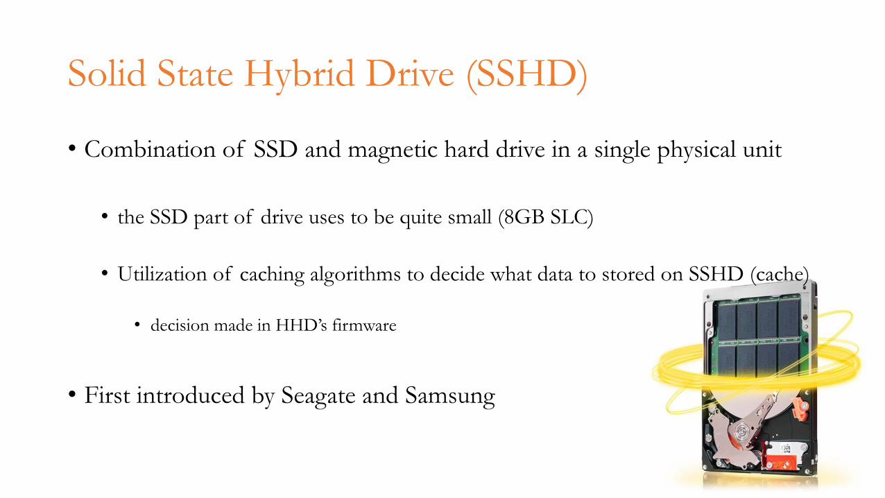
• Combination of SSD and magnetic hard drive in a single physical unit
• the SSD part of drive uses to be quite small (8GB SLC)
• Utilization of caching algorithms to decide what data to stored on SSHD (cache)
• decision made in HHD’s firmware
• First introduced by Seagate and Samsung
Solid State Hybrid Drive (SSHD)
52

Optical Disk
• CD, DVD, Blu-ray
• Based on reflectance• pit = 0 (lack of reflection)
• bump/land = 1 (reflection)
• Data stored by laser and read by laser diode when spinning in the optical disc drive
• Optical drives operate (usually) with constant linear velocity (konstantní lineární rychlost)(CLV) • magnetic HDDs operate with
constant angular velocity (konstantní úhlová rychlost) (CAV)
• audio streaming requires constant bit rate
• spindle motor has to vary speed to increase revolutions per minute (RPMs) near the center of the disk
53

Magnetic Tape
• Magnetizable coating on a long, narrow strip of plastic film
• Sequential access → well suited for transfer of big continuous blocks
• Low cost per bit• available surface area on a tape is far
greater than for HDD
• Read and written by tape drive
• Originally main secondary storage
• Performance
• slow access time• transfer rate comparable to magnetic
disks
• Automatic change of tapes• single tape drive
• autoloaders
• multiple tape drives• tape library, tape robot, tape jukebox• can store up to hundreds of petabytes of
data
• Usage• backups of infrequently used
information, archiving• longer duration (15-30 yrs)
55

Tape Libraries
• Tape robot, tape jukebox
• tape drive(s)• tape cartridges• robot• barcode reader
• identification of tape cartridges
• Capacity• up to hundreds of petabytes of data
• Price• up to $1 million
• Autoloaders• small tape libraries with only 1 drive
2 tape drives
15 tape cartridges
robot56

57

Hierarchical storage management
• Using various types of storages to increase usable capacity with limited costs• Less often used data moved to cheaper storages with higher capacity → tiers
• slower disks
• MAID - Massive Array of Idle Disks
• disk libraries
• Conceptually analogous to the (multi-level) cache
• Moving of data is managed by a migration policy
• May and may not require special commands
• CESNET (about 21 PB)
58