data sheet 10/68-2.91-en rev. a rsde10 / rsde20 … · rsde10 / rsde20 (contrac) electrical linear...
TRANSCRIPT
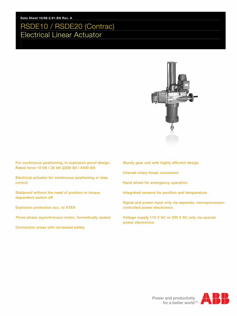
Data Sheet 10/68-2.91-EN Rev. A
RSDE10 / RSDE20 (Contrac) Electrical Linear Actuator
For continuous positioning, In explosion-proof design, Rated force 10 kN / 20 kN (2200 lbf / 4400 lbf) Electrical actuator for continuous positioning or step control Stallproof without the need of position or torque dependent switch-off Explosion protection acc. to ATEX Three-phase asynchronous motor, hermetically sealed Connection areas with increased safety
Sturdy gear unit with highly efficient design Internal rotary-linear conversion Hand wheel for emergency operation Integrated sensors for position and temperature Signal and power input only via separate, microprocessor-controlled power electronics Voltage supply 115 V AC or 230 V AC only via special power electronics
Contents

Electrical Linear Actuator RSDE10 / RSDE20 (Contrac) 10/68-2.91-EN For continuous positioning, In explosion-proof design,
2
Contents 1 Ex design..............................................................................................................................................................3 2 Technical data......................................................................................................................................................4
2.1 Actuator ..........................................................................................................................................................4 2.2 General information........................................................................................................................................4 2.3 Explosion-protection information....................................................................................................................5 2.4 Terminals in EEx D area ................................................................................................................................5 2.5 Tapped holes for cable glands .......................................................................................................................5
3 Electrical connection ..........................................................................................................................................6 3.1 Power Electronic Unit EBN853 (Contrac) ......................................................................................................6 3.2 Power Electronic Unit EBS852 (Contrac).......................................................................................................8
4 Dimensions ..........................................................................................................................................................9 4.1 Linear actuator ...............................................................................................................................................9
5 Ordering information.........................................................................................................................................11
Data Sheet Electrical Linear Actuator RSDE10 / RSDE20 (Contrac)
For continuous positioning,

Electrical Linear Actuator RSDE10 / RSDE20 (Contrac) 10/68-2.91-EN For continuous positioning, Rated force 10 kN / 20 kN (2200 lbf / 4400 lbf)
3
1 Ex design Wechsel ein-auf zweispaltig
This data sheet provides information about explosion-proof actuators. For additional information regarding the relevant Contrac power electronic unit and the motor temperature monitoring unit, refer to the corresponding data sheet.
Compact actuator for the operation of final control elements with preferably linear movement. The actuator thrust rod transfers the force directly to the final control element. A continuous power electronic unit controls the actuator. The electronic unit serves as the interface between actuator and control system.
During continuous positioning the power electronic unit varies the motor torque steplessly until the actuator force and the restoring process forces are balanced. High response sensitivity and high positioning accuracy with short positioning time ensure an excellent control quality and a long actuator life.
Note The ANSI information appears in parentheses after the SI information.
Wechsel ein-auf zweispaltig
� DCS / controller
115 V AC / 230 V AC
motor temperature
monitoring unit
(z.B. SD241B)
Contrac
electronic unit
Contrac actuator
in explosion-proof designM00266
non-explosive area
explosive area
motor with
temperature sensor
brake
motor- /
brake cable
(screened)
sensor cable
(screened)
signal cable from / to DCS
/ controller (screened)
motor wiring chamber
sensor wiring chamber
(anti-condensation heater
optional)
sensor electronics
position sensor
temperature
sensor cable
Fig. 1: Ex design
Electrical Linear Actuator RSDE10 / RSDE20 (Contrac) 10/68-2.91-EN For continuous positioning, Rated force 10 kN / 20 kN (2200 lbf / 4400 lbf)
4
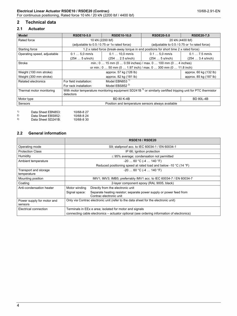
2 Technical data
2.1 Actuator
Model RSDE10-5.0 RSDE10-10,0 RSDE20-5.0 RSDE20-7,5 Rated force 10 kN (2200 lbf)
(adjustable to 0.5 / 0.75 or 1x rated force) 20 kN (4400 lbf)
(adjustable to 0.5 / 0.75 or 1x rated force) Starting force 1.2 x rated force (break-away torque in end positions for short time 2 x rated force) Operating speed, adjustable 0.1 … 5,0 mm/s
(254 … 5 s/inch) 0.1 … 10,0 mm/s
(254 … 2.5 s/inch) 0.1 … 5,0 mm/s (254 … 5 s/inch)
0.1 … 7.5 mm/s (254 … 3.4 s/inch)
Stroke min.: 0 … 15 mm (0 … 0.59 inches) / max. 0 … 100 mm (0 … 4 inches) or min.: 0 … 50 mm (0 … 1.97 inch) / max. 0 … 300 mm (0 … 11.8 inch)
Weight (100 mm stroke) Weight (300 mm stroke)
approx. 57 kg (126 lb) approx. 82 kg (181 lb)
approx. 60 kg (132 lb) approx. 85 kg (187 lb)
Related electronics For field installation: Model EBN853 1) For rack installation: Model EBS852 2)
Thermal motor monitoring With motor temperature monitoring equipment SD241B 3) or similarly certified tripping unit for PTC thermistor detectors
Motor type BD 80 K-4B BD 80L-4B Sensors Position and temperature sensors always available
1) Data Sheet EBN853: 10/68-8 27 2) Data Sheet EBS852: 10/68-8 24 3) Data Sheet SD241B: 10/68-8 30
2.2 General information
RSDE10 / RSDE20
Operating mode S9; stallproof acc. to IEC 60034-1 / EN 60034-1 Protection Class IP 66; Ignition protection Humidity ≤ 95% average; condensation not permitted Ambient temperature -20 … 60 °C (-4 … 140 °F)
Reduced positioning speed at rated load and below -10 °C (14 °F) Transport and storage temperature
-20 … 60 °C (-4 … 140 °F)
Mounting position IMV1; IMV3; IMB5; preferrably IMV1 acc. to IEC 60034-7 / EN 60034-7 Coating 2-layer component epoxy (RAL 9005, black) Anti-condensation heater Motor winding Directly from the electronic unit
Signal space: Separate heating resistor; separate power supply or power feed from Contrac electronic unit
Power supply for motor and sensors
Only via Contrac electronic unit (refer to the data sheet for the electronic unit)
Electrical connection Terminals in EEx e area; isolated for motor and signals connecting cable electronics – actuator optional (see ordering information of electronics)

Electrical Linear Actuator RSDE10 / RSDE20 (Contrac) 10/68-2.91-EN For continuous positioning, Rated force 10 kN / 20 kN (2200 lbf / 4400 lbf)
5
A
2.3 Explosion-protection information
Explosion-proof Contrac actuators are classified as type II devices for operation in potentially explosive areas for days and device category 2. They are designed for use in Ex zones 1 and 21. Can also be used in zones 2 and 22 (for gas and dust atmosphere). Applicable standards - EN 50 014 - EN 50 018 - EN 50 019 - EN 50 020 - EN 50 281-1-1 - EN 13 463-1 - EN 13 463-5 - EN 13 463-8 Explosion-protection for actuator components
Actuator components Explosion protection Motor with brake II GD EEx de IIB T4 Gearing II 2GD ck T4 Actuator sensor II 2G EEx [ib] ib IIC T4 Anti-condensation heater II 2G EEx d II C Connection areas II 2G/D EEx e II B T4 Full identification II 2 GD ck EEx de [ib] ib II B T4 or IP6x T=130 °C ZELM 04 ATEX 0209 X
Terminals on actuator in EExe area
2.4 Terminals in EEx D area
Motor / brake Signals
Conductor cross-section
max. 2.5 mm2 (14 AWG) max. 2.5 mm2 (14 AWG)
2.5 Tapped holes for cable glands
Tap holes for cable glands metric optional adapters for* Signals M20 x 1.5 (2 x) PG 16 (2 x) NPT ½” (2 x) Motor M25 x 1.5 (1 x) PG 21 (1 x) NPT ¾” (1 x) Temperature sensor M20 x 1.5 (1 x) PG 16 (2 x) NPT ½” (2 x)
* adapter for PG or NPT thread must be ordered separately
The onsite cable glands for the motor and signals must be in EEx e design and provide shield connection.
Note Use only the proper cable for the electrical connection between the Contrac actuator in the Ex area and the components in the Ex-free area. For the motor/brake line, the sensor lead and the signal line from/to the control system/controller, cables must be shielded. Connect the shield for the motor/brake line and sensor lead on both sides (on the actuator and at the Contrac power electronic unit). For the connection between the motor and motor temperature monitoring unit and for the network connection, cables do not have to be shielded.

Electrical Linear Actuator RSDE10 / RSDE20 (Contrac) 10/68-2.91-EN For continuous positioning, Rated force 10 kN / 20 kN (2200 lbf / 4400 lbf)
6
3 Electrical connection
3.1 Power Electronic Unit EBN853 (Contrac)
3.1.1 Analog / Digital
Note The electrical connection is provided by terminals on the actuator and on the electronic unit.
24V
30
+ - -+
RB
+ -
31
I
U
26 271
+ - + - + - + -
72 83 94 10 135 11 146 12 15L N
17 19 20 21 22 23 24
SD241B
U1 V1 70 171 2W1 1 2
�
17 19 20 21 22 23 24U V W Br Br PE
PE
H1 H2
11
Uv24V
+
RB
+ -
28 29
10
18
mains
M00208
M3~
motor brake Contrac ex-actuator
sensors
Ex
non-Ex
heater approx 6 W (option)*
screen connected to both ends
o n e - s i d e d s c r e e n i n g
in further wiring possible
transmitter4...20mA
Setpoint+ HART
0/4...20mAact. pos.
0/4...20mABA 1
o.k./faultBA 2
endp. 0%
BA 3endp. 100%
BE 1MAN/AUT
BE 2MAN(+)
BE 3MAN (-)
Uvout
sub distribution board
Contrac electronic unit
ext. fuse
motor
conn. chamber
sensor
conn. chamber
115 V AC / 230 V AC
Fig. 2: Electrical connection: Ex actuator analog / digital
Installation information on the cable harness for actuators in Ex design The electrical connection between the Contrac electronic unit and the Contrac actuator can be established using the cable harness (order code 695). The cable harness is not part of the Ex prototype test certificate and must therefore be tested for safety-relevant functionality within the complete installation by the installer or operator. If the specified cable harness does not meet all safety-relevant requirements, the proper installation material must be used. For the specified motor connecting cable, the screen must be connected at both ends and grounded.
Electrical Linear Actuator RSDE10 / RSDE20 (Contrac) 10/68-2.91-EN For continuous positioning, Rated force 10 kN / 20 kN (2200 lbf / 4400 lbf)
7
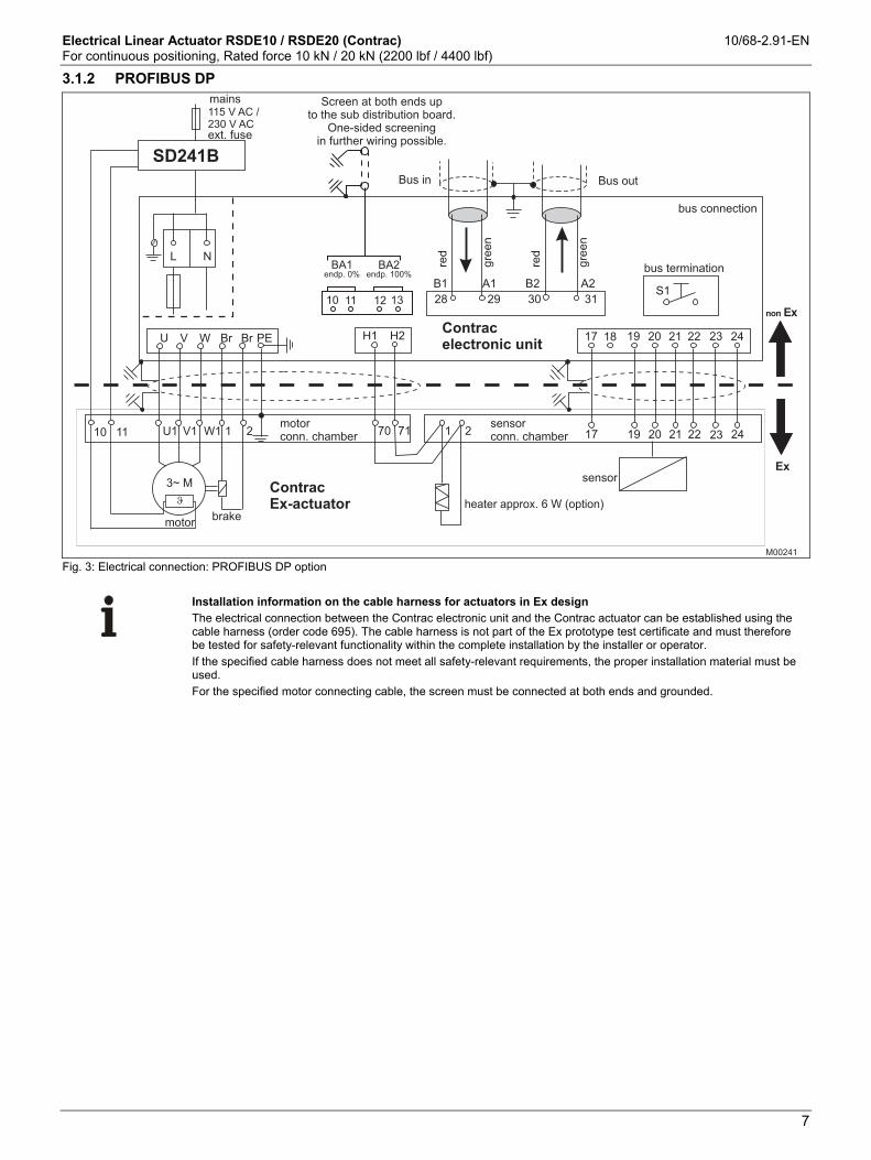
3.1.2 PROFIBUS DP
M00241
B1 B2A1 A2
Contrac
electronic unit
bus connection
bus termination
red
red
gre
en
gre
en
U1 V1 W1 1 2
�
3~ M
10 11 70 71
17 19 20 21 22 23 24
17 19 20 21 22 23 241 2
28 29 30 31
U V W Br Br PE H1 H2
L N
Bus outBus in
S1
SD241B
18
non Ex
Ex
heater approx. 6 W (option)
motor
conn. chamber
sensor
conn. chamber
motorbrake
Contrac
Ex-actuator
mains
ext. fuse
sensor
BA1endp. 0%
BA2endp. 100%
10 1311 12
115 V AC /
230 V AC
Screen at both ends up
to the sub distribution board.
One-sided screening
in further wiring possible.
Fig. 3: Electrical connection: PROFIBUS DP option :
Installation information on the cable harness for actuators in Ex design The electrical connection between the Contrac electronic unit and the Contrac actuator can be established using the cable harness (order code 695). The cable harness is not part of the Ex prototype test certificate and must therefore be tested for safety-relevant functionality within the complete installation by the installer or operator. If the specified cable harness does not meet all safety-relevant requirements, the proper installation material must be used. For the specified motor connecting cable, the screen must be connected at both ends and grounded.

Electrical Linear Actuator RSDE10 / RSDE20 (Contrac) 10/68-2.91-EN For continuous positioning, Rated force 10 kN / 20 kN (2200 lbf / 4400 lbf)
8
3.2 Power Electronic Unit EBS852 (Contrac)
3.2.1 Analog / Digital
Note The electrical connection is provided by terminals on the actuator and on the electronic unit.
Fig. 4: Electrical connection: Ex actuator analog / binary
Note * For separate heat supply, protect the heater with 2 … max. 6 A medium time-lag fuses (e.g., Neozed D01CE14).
Installation information on the cable harness for actuators in Ex design The electrical connection between the Contrac electronic unit and the Contrac actuator can be established using the cable harness (order code 695). The cable harness is not part of the Ex prototype test certificate and must therefore be tested for safety-relevant functionality within the complete installation by the installer or operator. If the specified cable harness does not meet all safety-relevant requirements, the proper installation material must be used. For the specified motor connecting cable, the screen must be connected at both ends and grounded.
Electrical Linear Actuator RSDE10 / RSDE20 (Contrac) 10/68-2.91-EN For continuous positioning, Rated force 10 kN / 20 kN (2200 lbf / 4400 lbf)
9
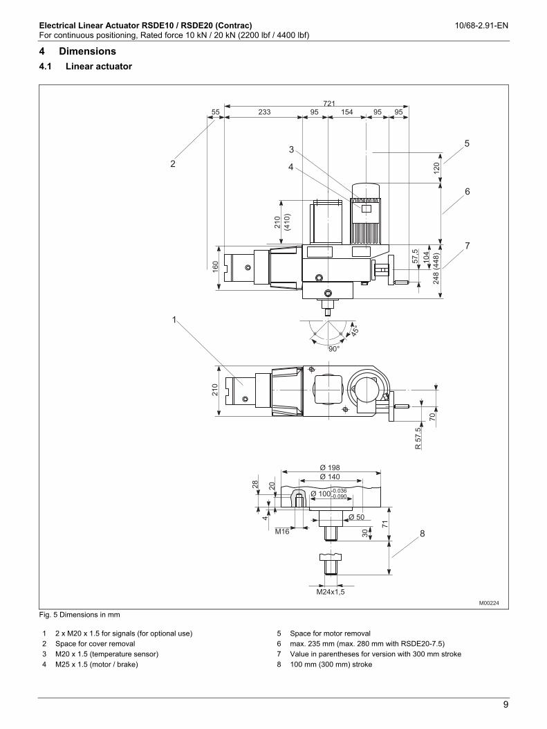
4 Dimensions
4.1 Linear actuator
Fig. 5 Dimensions in mm 1 2 x M20 x 1.5 for signals (for optional use) 5 Space for motor removal 2 Space for cover removal 6 max. 235 mm (max. 280 mm with RSDE20-7.5) 3 M20 x 1.5 (temperature sensor) 7 Value in parentheses for version with 300 mm stroke 4 M25 x 1.5 (motor / brake) 8 100 mm (300 mm) stroke

Electrical Linear Actuator RSDE10 / RSDE20 (Contrac) 10/68-2.91-EN For continuous positioning, Rated force 10 kN / 20 kN (2200 lbf / 4400 lbf)
10
Fig. 6 Dimensions in inches 1 2 x M20 x 1.5 for signals (for optional use) 5 Space for motor removal 2 Space for cover removal 6 max. 9.25 inch (max. 11.02 inches with RSDE20-7.5) 3 M20 x 1.5 (temperature sensor) 7 Value in parentheses for version with 11.8 inch stroke 4 M25 x 1.5 (motor / brake) 8 3.94 inch (11.8 inch) stroke

Electrical Linear Actuator RSDE10 / RSDE20 (Contrac) 10/68-2.91-EN For continuous positioning, Rated force 10 kN / 20 kN (2200 lbf / 4400 lbf)
11
Order information
5 Ordering information
Linear Actuator Variant digit No. 1 - 7 8 9 10 11 CodeRSDE10 -5,0, RSDE10-10,0 Catalog No. V68635-Rated force 10 kN (2200 lbs) (adjustable to 50%/75%/100%)RSDE20 -5,0, RSDE20-7,5 Catalog No. V68645-Rated force 20 kN (4400 lbs) (adjustable to 50%/75%/100%)Rated stroke100 mm (4.0 in) 1 2300 mm (11.8 in) 1 6Rated speed5.0 mm/s (5.0 s/in) (adjustable to 5.0 ... 0.1 mm/s) only for RSDE10-5,0 1 010.0 mm/s (2.5 s/in) (adjustable to 10.0 ... 0.1 mm/s) only for RSDE10-10,0 1 15.0 mm/s (5.0 s/in) (adjustable to 5.0 ... 0.1 mm/s) only for RSDE20-5,0 1 27.5 mm/s (3.4 s/in) (adjustable to 7.5 ... 0.1 mm/s) only for RSDE20-7,5 1 3
Special actuator featuresSelect at least one feature per groupElectrical connection terminals in EEx con. chamber 269Ambient temperature range -20 ... 60 °C (-4 ... 140 °F) 348
Additional ordering informationCode
Electrical connection thread Set NPT adapter (joint metric / NPT thread) 680Set PG adapter (joint metric / PG thread) 681
Anti condensation heater 360Identification on data label (alphanumeric, max. 32 characters) 294Data label with US units 253Factory certificate 2.1 acc. to EN 10204 291Certificate B acc. to EN 10204 292Assembly with valve at ABB (order and pos. no. of valve required) 481Operating instruction (specify total quantity required, 1 copy without extra charge)
German (no specification for 1 copy) Z1DEnglish (always state Code-No.) Z1E
Attention!Electronic unit to be ordered separately
Note: Delivery time for max. 2 pcs. For 3 pcs. or more delivery time on request.

Contact us
10/6
8-2.
91-E
NR
ev.A
12.2
010
|3K
XE16
1005
R10
01ABB Ltd. Process Automation Salterbeck Trading Estate Workington, Cumbria CA14 5DS UK Phone: +44 (0)1946 830 611 Fax: +44 (0)1946 832 661 ABB Inc. Process Automation 125 E. County Line Road Warminster, PA 18974 USA Phone: +1 215 674 6000 Fax: +1 215 674 7183 ABB Automation Products GmbH Process Automation Schillerstr. 72 32425 Minden Germany Phone: +49 551 905-534 Fax: +49 551 905-555 www.abb.com
Note We reserve the right to make technical changes or modify the contents of this document without prior notice. With regard to purchase orders, the agreed particulars shall prevail. ABB does not accept any responsibility whatsoever for potential errors or possible lack of information in this document. We reserve all rights in this document and in the subject matter and illustrations contained therein. Any reproduction, disclosure to third parties or utilization of its contents - in whole or in parts – is forbidden without prior written consent of ABB. Copyright© 2010 ABB All rights reserved