data sheet d184s035u02 rev. 10 fv4000, fs4000 vortex
TRANSCRIPT

Data Sheet D184S035U02 Rev. 10
FV4000, FS4000 Vortex Flowmeter / Swirl Flowmeter
2-wire Compact Design Digital Signal Processor Converter Technology
For metering liquids, gases and steam FV4000 Vortex flowmeter FS400 Swirl flowmeter for very short steadying zones Approvals for explosion protection — ATEX — IEC — cFMus
Zone 1, Zone 2, dust ignition protection
Magnetic pen operation — Configuration also possible with closed housing Integrated switching output — Used as limit contact or pulse output Compensation of temperature influences by means of temperature measurement integrated as an option
Contents
Vortex Flowmeter / Swirl Flowmeter FV4000 / FS4000 D184S035U02
2
Contents 1 Principles of measurement ................................................................................................................................4
1.1 Principle of measurement for Vortex flowmeter .............................................................................................4 1.2 Principle of measurement for Swirl flowmeter................................................................................................4
2 Overview of flowmeters ......................................................................................................................................5 3 General specifications ........................................................................................................................................7
3.1 Nominal diameter selection............................................................................................................................7 3.2 Measured value deviation for flow measurement ..........................................................................................7 3.3 Measured value deviation for temperature.....................................................................................................7 3.4 Reference conditions for flow measurement..................................................................................................8 3.5 FV4000-VT4 / VR4 flowrates .........................................................................................................................8 3.6 FS4000-ST4 / SR4 flowrates .........................................................................................................................9 3.7 Static overpressure in the case of fluids ........................................................................................................9 3.8 Overload capability.........................................................................................................................................9 3.9 Temperature of medium...............................................................................................................................10 3.10 Flowmeter insulation ....................................................................................................................................10 3.11 Ambient conditions .......................................................................................................................................10 3.12 Installation Requirements.............................................................................................................................11 3.13 Recommended inflow and outflow sections.................................................................................................11 3.14 Installation at high media temperatures > 150°C (302°F)............................................................................12 3.15 Installation for pressure and temperature measurement .............................................................................12 3.16 Installation of final controlling equipment .....................................................................................................12 3.17 Process connections ....................................................................................................................................13 3.18 Materials .......................................................................................................................................................13 3.19 Weights.........................................................................................................................................................13
4 Dimensions ........................................................................................................................................................15 4.1 FV4000-VT4/VR4 (TRIO-WIRL V), wafer design.........................................................................................15 4.2 FV4000-VT4/VR4 (TRIO-WIRL V), flange design, DIN ...............................................................................16 4.3 FV4000-VT4/VR4 (TRIO-WIRL V), flange design, ASME ...........................................................................18 4.4 FS4000-ST4/SR4 (TRIO-WIRL S) ...............................................................................................................20
5 Transmitter specifications................................................................................................................................22 6 Communication .................................................................................................................................................23
6.1 2-wire technology design..............................................................................................................................23 6.2 4 ... 20 mA / HART .......................................................................................................................................23 6.3 PROFIBUS PA .............................................................................................................................................25 6.4 FOUNDATION Fieldbus...............................................................................................................................26
7 Ex relevant specifications for transmitter.......................................................................................................27 7.1 Ex "ib" / Ex "n" design for VT41/ST41 and VR41/SR41 (4 ... 20 mA / HART).............................................27 7.2 Ex "d" / Ex "ib" / Ex "n" design for VT42/ST42 and VR42/SR42 (4 ... 20 mA / HART) ................................29 7.3 FM approval design for the USA and Canada for VT43/ST43 and VR43/SR43 (4 ... 20 mA / HART)........31
Vortex Flowmeter / Swirl Flowmeter FV4000 / FS4000 D184S035U02
3
7.4 EEX "ia" design for VT4A/ST4A and VR4A/SR4A (fieldbus) .......................................................................34 8 Ordering information.........................................................................................................................................36
8.1 FV4000-VT4/VR4 Vortex flowmeter.............................................................................................................36 8.2 FS4000-ST4/SR4 Swirl flowmeter ...............................................................................................................38
9 Accessories .......................................................................................................................................................40 10 Questionnaire ....................................................................................................................................................41
Data Sheet Vortex Flowmeter / Swirl Flowmeter FV4000 / FS4000

Vortex Flowmeter / Swirl Flowmeter FV4000 / FS4000 D184S035U02
4
1 Principles of measurement Change from one to two columns A
1.1 Principle of measurement for Vortex flowmeter
The operating principle of the Vortex flowmeter is based on the Karman street. As the fluid flows over and under the solid body, vortices are shed alternately above and below. The shedding of these vortices due to the flow forms a vortex trail (Karman street).
G00680
1 2
Fig. 1: Principle of measurement, FV4000
1 Solid body 2 Piezo sensor The frequency f of vortex shedding is proportional to the flow velocity v and inversely proportional to the width of the solid body d:
dvStf ×=
St, known as the Strouhal number, is a dimensionless number which has a decisive impact on the quality of vortex flow measurement. If the solid body is dimensioned appropriately, the Strouhal number St will be constant across a very wide range of the Reynolds number Re (Fig. 2).
ϑ×
=DvRe
ϑ = Kinematic viscosity D = Nominal size of meter tube Consequently, the vortex shedding frequency to be evaluated is dependent solely upon the flow velocity and not at all upon media density and viscosity. The local changes in pressure induced by vortex shedding are detected by a piezo sensor and converted into electrical pulses corresponding to the vortex frequency. The frequency signal from the flowmeter sensor, which is proportional to the flow, undergoes downstream processing in the transmitter.
G00602
L
St
Re
Fig. 2: How the Strouhal number is dependent upon the Reynolds
number St Strouhal number Re Reynolds number L Linear flow area
A
1.2 Principle of measurement for Swirl flowmeter
The inlet pipe converts the axial flow of the incoming media into rotational movement. In the center of this rotation a vortex core is formed which is forced into a secondary spiral-shaped rotation by the backflow. The frequency of this secondary rotation is proportional to the flow and, if the internal geometry of the meter exhibits an optimum design, will be linear over a wide flow range. This frequency is measured by a piezo sensor. The frequency signal from the flowmeter sensor, which is proportional to the flow, undergoes downstream processing in the transmitter.
G00601
1 3
5 4
2
Fig. 3
1 Inlet pipe 2 Piezo sensor 3 Outlet pipe
4 Stagnation point 5 Housing
Change from one to two columns
Vortex Flowmeter / Swirl Flowmeter FV4000 / FS4000 D184S035U02
5
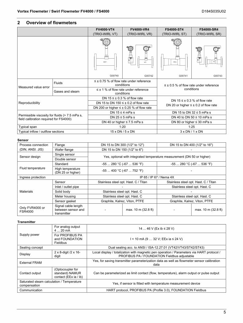
2 Overview of flowmeters
FV4000-VT4 (TRIO-WIRL VT)
FV4000-VR4 (TRIO-WIRL VR)
FS4000-ST4 (TRIO-WIRL ST)
FS4000-SR4 (TRIO-WIRL SR)
G00740 G00742 G00741 G00743
Fluids ≤ ± 0.75 % of flow rate under reference conditions
Measured value error Gases and steam ≤ ± 1 % of flow rate under reference
conditions
≤ ± 0.5 % of flow rate under reference conditions
DN 15 ≤ ± 0.3 % of flow rate DN 15 to DN 150 ≤ ± 0.2 of flow rate Reproducibility
DN 200 or higher ≤ ± 0.25 % of flow rate
DN 15 ≤ ± 0.3 % of flow rate DN 20 or higher ≤ ± 0.2 of flow rate
DN 15 ≤ 4 mPa s DN 15 to DN 32 ≤ 5 mPa s DN 25 ≤ 5 mPa s DN 40 to DN 50 ≤ 10 mPa s Permissible viscosity for fluids (> 7.5 mPa s,
field calibration required for FS4000) DN 40 or higher ≤ 7.5 mPa s DN 80 or higher ≤ 30 mPa s
Typical span 1:20 1:25 Typical inflow / outflow sections 15 x DN / 5 x DN 3 x DN / 1 x DN
Sensor
Flange DN 15 to DN 300 (1/2" to 12") DN 15 to DN 400 (1/2" to 16") Process connection (DIN, ANSI. JIS) Wafer flange DN 15 to DN 150 (1/2" to 6") -
Single sensor Sensor design
Double sensor Yes, optional with integrated temperature measurement (DN 50 or higher)
Standard -55 ... 280 °C (-67 ... 536 °F) -55 ... 280 °C (-67 ... 536 °F) Fluid temperature High temperature
(DN 25 or higher) -55 ... 400 °C (-67 ... 752 °F) -
Ingress protection IP 65 / IP 67 / Nema 4X Sensor Stainless steel opt. Hast. C / Titan Stainless steel opt. Hast. C / Titan Inlet / outlet pipe - Stainless steel opt. Hast. C Solid body Stainless steel opt. Hast. C - Meter housing Stainless steel opt. Hast. C Stainless steel opt. Hast. C
Materials
Sensor gasket Graphite, Kalrez, Viton, PTFE Graphite, Kalrez, Viton, PTFE
Only FVR4000 or FSR4000
Signal cable length between sensor and transmitter
- max. 10 m (32.8 ft) - max. 10 m (32.8 ft)
Transmitter
For analog output 4 ... 20 mA 14 ... 46 V (Ex ib ≤ 28 V)
Supply power For PROFIBUS PA and FOUNDATION Fieldbus
I < 10 mA (9 … 32 V; EEx ia ≤ 24 V)
Sealing concept Dual sealing acc. to ANSI / ISA-12.27.01 (VT42/VT43/ST42/ST43)
Display 2 x 8-digit /2 x 16-digit
Local display / totalization with magnetic pen operation / Parameters via HART protocol / PROFIBUS PA / FOUNDATION Fieldbus adjustable
External FRAM Yes, for saving transmitter parameterization data as well as flowmeter sensor calibration data
Contact output (Optocoupler for standard) NAMUR contact (EEx ia / ib)
Can be parameterized as limit contact (flow, temperature), alarm output or pulse output
Saturated steam calculation / Temperature compensation Yes, if sensor is fitted with temperature measurement device
Communication HART protocol, PROFIBUS PA (Profile 3.0), FOUNDATION Fieldbus

Vortex Flowmeter / Swirl Flowmeter FV4000 / FS4000 D184S035U02
6
Designs There are generally two different designs.
G00699 Vortex flowmeter
FV4000-VT4 Wafer flange design
Vortex flowmeter FV4000-VT4
Flange design
Swirl flowmeter FS4000-ST4
Flange design
Fig. 4: Integral mount design: The transmitter is installed directly on the sensor.
G00700 Vortex flowmeter
FV4000-VR4 Wafer flange design
Vortex flowmeter FV4000-VR4 Flange design
Swirl flowmeter FS4000-SR4 Flange design
Fig. 5: Remote mount design: The transmitter can be installed up to 10 m away from the flowmeter sensor. The cable is permanently connected to the transmitter. It can be made shorter if required.

Vortex Flowmeter / Swirl Flowmeter FV4000 / FS4000 D184S035U02
7
3 General specifications Change from one to two columns A
3.1 Nominal diameter selection
The nominal diameter is selected on the basis of the maximum operating flow Qv max. If maximum spans are to be achieved, this should not be less than half the maximum flowrate for each nominal diameter (Qv max DN), although reduction to approx. 0.15 Qv max DN is possible. The linear lower range limit value is dependent upon the Reynolds number (see accuracy information). If the flow to be measured is the standard flow (standard condition: 0 °C (32 °F), 1,013 mbar) or mass flowrate, this must be converted to the operating flow and the most appropriate nominal device diameter must be selected from the flow range tables (Tables 1, 2, 3). ρ = Operating density (kg/m3) ρN = Standard density (kg/m3) P = Operating pressure (bar) T = Operating temperature (°C) Qv = Operating flow (m3/h) Qn = Standard flow (m3/h) Qm = Mass flowrate (kg/h) η = Dynamic viscosity (Pas) ν = Kinematic viscosity (m2/s) 1. Conversion of standard density (ρn) --> operating density (ρ)
T,,
n +×
ρ+×ρ=ρ
273273
01310131
2. Conversion to operating flow (Qv) a) From standard flow (Qn) -->
273273
01310131 T
p,,QQQ n
nnV
+×
+=
ρρ
=
b) From mass flowrate (Qm) -->
ρ= m
VQQ
3. Dynamic viscosity (η) --> kinematic viscosity (ν)
ρη
=ν
Calculating the Reynolds number:
( )d2827QRe
⋅ν⋅=
Q = Flow in m3/h d = Pipe diameter in m ν = Kinematic viscosity m2/s (1 cst = 10-6 m2/s) The current Reynolds number can also be calculated using our AP-Calc calculation program.
3.2 Measured value deviation for flow measurement
Deviation in percentage terms from the measured value under reference conditions (including the transmitter) in the linear measuring range between Re min and Qmax (see "Measuring ranges" table).
FV4000-VT4/VR4 FS4000-ST4/SR4 Fluids ≤ ± 0,75 % Gases / Steam ≤ ± 1 %
± 0,5 %
Current output Additional measurement uncertainty
< 0,1 %
Temperature effect < 0,05 % / 10 K
Misalignment associated with installation or deinstallation may affect the measuring error. Additional measuring errors may occur if there are deviations from the reference conditions. 3.2.1 Reproducibility as a percentage of the
measured value
DN Inch FV4000-VT4/VR4
FS4000-ST4/SR4
15 1/2“ 0,3 % 25 ... 250 1“ ... 6“ 0,2 % 200 ... 300 8“ ... 12“ 0,25 % 0,2 %
3.3 Measured value deviation for temperature
Measured value deviation (including transmitter) ± 2 °C Reproducibility ≤ 0.2 % of measured value
Product selection and dimensioning program
Important The ABB "AP-Calc" program can be used free of charge when selecting an appropriate flowmeter for a given application. The program runs in a Microsoft WINDOWS ® environment.
Vortex Flowmeter / Swirl Flowmeter FV4000 / FS4000 D184S035U02
8
Change from one to two columns A
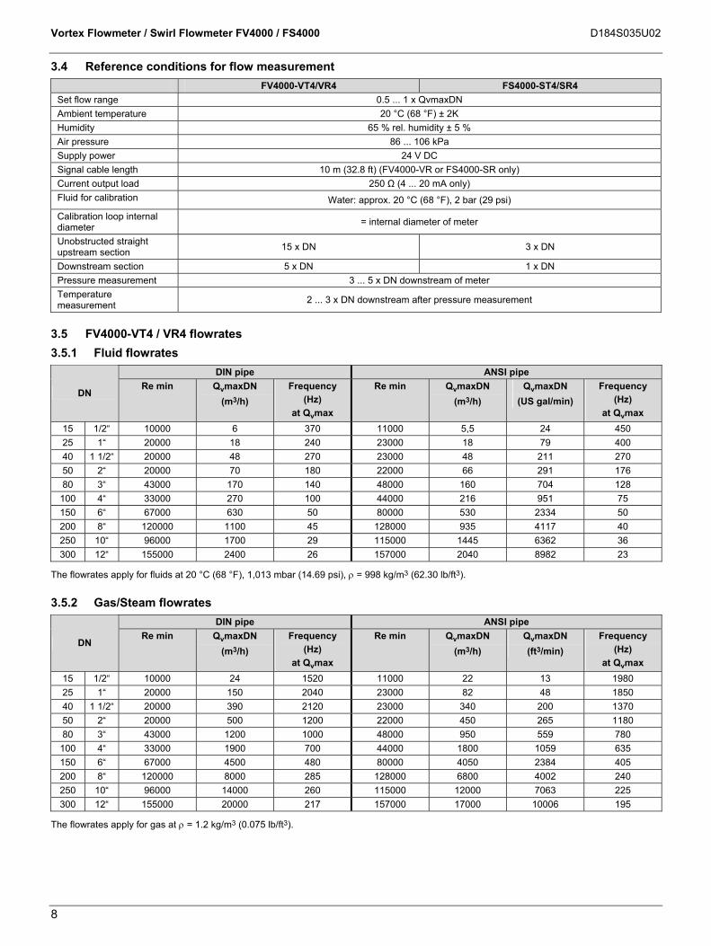
3.4 Reference conditions for flow measurement
FV4000-VT4/VR4 FS4000-ST4/SR4 Set flow range 0.5 ... 1 x QvmaxDN Ambient temperature 20 °C (68 °F) ± 2K Humidity 65 % rel. humidity ± 5 % Air pressure 86 ... 106 kPa Supply power 24 V DC Signal cable length 10 m (32.8 ft) (FV4000-VR or FS4000-SR only) Current output load 250 Ω (4 ... 20 mA only) Fluid for calibration Water: approx. 20 °C (68 °F), 2 bar (29 psi)
Calibration loop internal diameter = internal diameter of meter
Unobstructed straight upstream section 15 x DN 3 x DN
Downstream section 5 x DN 1 x DN Pressure measurement 3 ... 5 x DN downstream of meter Temperature measurement 2 ... 3 x DN downstream after pressure measurement
A
3.5 FV4000-VT4 / VR4 flowrates
3.5.1 Fluid flowrates
DIN pipe ANSI pipe
DN Re min QvmaxDN
(m3/h) Frequency
(Hz) at Qvmax
Re min QvmaxDN (m3/h)
QvmaxDN (US gal/min)
Frequency (Hz)
at Qvmax 15 1/2“ 10000 6 370 11000 5,5 24 450 25 1“ 20000 18 240 23000 18 79 400 40 1 1/2“ 20000 48 270 23000 48 211 270 50 2“ 20000 70 180 22000 66 291 176 80 3“ 43000 170 140 48000 160 704 128 100 4“ 33000 270 100 44000 216 951 75 150 6“ 67000 630 50 80000 530 2334 50 200 8“ 120000 1100 45 128000 935 4117 40 250 10“ 96000 1700 29 115000 1445 6362 36 300 12“ 155000 2400 26 157000 2040 8982 23
The flowrates apply for fluids at 20 °C (68 °F), 1,013 mbar (14.69 psi), ρ = 998 kg/m3 (62.30 lb/ft3).
3.5.2 Gas/Steam flowrates
DIN pipe ANSI pipe
DN Re min QvmaxDN
(m3/h) Frequency
(Hz) at Qvmax
Re min QvmaxDN (m3/h)
QvmaxDN (ft3/min)
Frequency (Hz)
at Qvmax 15 1/2“ 10000 24 1520 11000 22 13 1980 25 1“ 20000 150 2040 23000 82 48 1850 40 1 1/2“ 20000 390 2120 23000 340 200 1370 50 2“ 20000 500 1200 22000 450 265 1180 80 3“ 43000 1200 1000 48000 950 559 780 100 4“ 33000 1900 700 44000 1800 1059 635 150 6“ 67000 4500 480 80000 4050 2384 405 200 8“ 120000 8000 285 128000 6800 4002 240 250 10“ 96000 14000 260 115000 12000 7063 225 300 12“ 155000 20000 217 157000 17000 10006 195
The flowrates apply for gas at ρ = 1.2 kg/m3 (0.075 lb/ft3).
Vortex Flowmeter / Swirl Flowmeter FV4000 / FS4000 D184S035U02
9
A
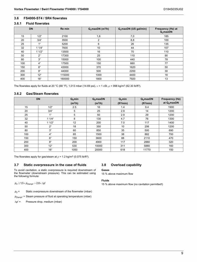
3.6 FS4000-ST4 / SR4 flowrates
3.6.1 Fluid flowrates
DN Re min QvmaxDN (m3/h) QvmaxDN (US gal/min) Frequency (Hz) at QvmaxDN
15 1/2“ 2100 1,6 7,0 185 20 3/4“ 3500 2 8,8 100 25 1“ 5200 6 26 135 32 1 1/4“ 7600 10 44 107 40 1 1/2“ 13500 16 70 110 50 2“ 17300 25 110 90 80 3“ 15000 100 440 78 100 4“ 17500 150 660 77 150 6“ 43000 370 1620 50 200 8“ 44000 500 2200 30 300 12“ 115000 1000 4400 16 400 16“ 160000 1800 7920 13
The flowrates apply for fluids at 20 °C (68 °F), 1,013 mbar (14.69 psi), ν = 1 cSt, ρ = 998 kg/m3 (62.30 lb/ft3).
3.6.2 Gas/Steam flowrates
DN QVmin (m3/h)
QVmaxDN (m3/h)
QVmin (ft3/min)
QVmaxDN (ft3/min)
Frequency (Hz) at QVmaxDN
15 1/2“ 2.5 16 1.4 9.4 1900 20 3/4“ 5 25 2.9 14 1200 25 1“ 5 50 2.9 29 1200 32 1 1/4“ 8 130 4.7 76 1300 40 1 1/2“ 12 200 7.0 117 1400 50 2“ 18 350 10 206 1200 80 3“ 60 850 35 500 690 100 4“ 65 1500 38 882 700 150 6“ 150 3600 88 2110 470 200 8“ 200 4900 117 2880 320 300 12“ 530 10000 311 5880 160 400 16“ 1050 20000 618 11770 150
The flowrates apply for gas/steam at ρ = 1.2 kg/m3 (0.075 lb/ft3). Change from one to two columns
3.7 Static overpressure in the case of fluids
To avoid cavitation, a static overpressure is required downstream of the flowmeter (downstream pressure). This can be estimated using the following formula:
p,p,p Dampf ′Δ×+×≥ 62312
2p = Static overpressure downstream of the flowmeter (mbar)
Dampfp = Steam pressure of fluid at operating temperature (mbar)
p′Δ = Pressure drop, medium (mbar)
3.8 Overload capability
Gases 15 % above maximum flow Fluids 15 % above maximum flow (no cavitation permitted!)

Vortex Flowmeter / Swirl Flowmeter FV4000 / FS4000 D184S035U02
10
3.9 Temperature of medium
Important Please note the information in the section titled "Explosion protection". Compliance with the permissible temperature range for the gaskets is mandatory.
FV4000-VT4/VR4 FS4000-ST4/SR4 Standard -55 ... 280 °C (-67 ... 536 °F)
HT design -55 ... 400 °C (-67 ... 752 °F)
-
3.10 Flowmeter insulation
The pipeline may be insulated up to a maximum of 100 mm (4 inch) upper edge. Use of trace heating Trace heating may be used under the following conditions: • If it is fixed directly on or around the pipeline • If, in the case of existing pipeline insulation, it is installed inside
the insulation (the maximum height of 100 mm (4 inch) must not be exceeded)
• If the maximum temperature the trace heating is able to produce ≤ the maximum temperature of the medium
The requirements to be met by integrators set out in EN 60079-14 must be complied with! Please note that the use of trace heaters will not impair EMC protection or generate additional vibrations.
G00672
1
Fig. 6: Flowmeter insulation
1 Maximum 100 mm (4 inch)
3.11 Ambient conditions
Resistance to climate to DIN 40040 Permissible ambient temperature range
Explosion protection / Model Temperature range -20 ... 70 °C (-4 … 158 °F) None /
VT40 and VR40 / ST40 and SR40 -55 … 70 °C (-67 … 158 °F)
-20 ... 70 °C (-4 … 158 °F) 1) Ex ib / VT41 and VR41 / ST41 and SR41 -40 … 70 °C (-67 … 158 °F) 1)
-20 ... 60 °C (-4 … 140 °F) Ex ia / VT4A and VR4A / ST4A and SR4A -30 ... 60 °C (-40 … 140 °F)
-20 ... 60 °C (-4 … 140 °F) Ex d / VT42 and VR42 / ST42 and SR42 -40 ... 60 °C (-40 … 140 °F)
-20 … 70 °C (-4 … 158 °F) CFMUS / VT43 and VR43 / ST43 and SR43 -45 … 70 °C (-49 … 158 °F)
1) Category 2D (dust-ignition proof) maximum 60° C (140° F) Permissible air humidity
Design Humidity Standard Relative humidity max. 85 %,
annual mean ≤ 65 % Climate-proof Relative humidity
≤ 100 % permanent
1)1
34
5
2
70
60
50
40
30
20
0
10
-10
-20 opt. -55
-50 0 50 100 150 160 250 280 400200
4
4
Fig. 7: Relationship between the temperature of the fluid and the
ambient temperature 1 Ambient temperature 2 Media temperature 3 Permissible temperature
range for standard design (≤ 280 °C (≤ 536 °F))
4 Installation for medium temperature > 150 °C (302 °F)
5 HT design (≤ 400 °C (≤ 752 °F)), FV4000-VT4 only
1) For the supply circuit (terminals 31 / 32) and the switching outputs 41 and 42, cables suitable for temperatures up to T = 110 °C (230 °F) may be used without restriction. Cables which are only suitable for temperatures up to T = 80 °C (176 °F) restrict the temperature ranges. These restrictions also apply to the VR version (remote design) and the PROFIBUS PA design with plug connector.
Important The legibility of the display can be impaired at temperatures < 0 °C (< 32 °F) and > 55 °C (> 131 °F). The functionality of the meter and the outputs remains unaffected by this. Please refer to the order information for ambient temperatures < -20 °C (< -4 °F). Please note the information in the section titled 7 "Ex relevant specifications for transmitter".

Vortex Flowmeter / Swirl Flowmeter FV4000 / FS4000 D184S035U02
11
3.12 Installation Requirements
A Vortex or Swirl flowmeter can be installed at any point in the pipeline system. However, the following installation conditions must be considered: • Compliance with the ambient conditions • Compliance with the recommended inflow/outflow sections • The flow direction must correspond to that indicated by the arrow
on the flowmeter sensor. • Compliance with the required minimum interval for removing the
transmitter and replacing the sensor • Avoidance of mechanical vibrations of the pipeline (by fitting
supports if necessary) • The internal diameter of the flowmeter sensor and the pipe must
be identical. • Avoidance of pressure vibrations at zero flow by fitting gates at
intervals in long pipeline systems • Attenuation of alternating (pulsating) flow during piston pump or
compressor conveying by using appropriate damping devices. The residual pulse must not exceed 10 %. The frequency of the conveying equipment must not be within the range of the measuring frequency of the flowmeter.
• Valves / gates should normally be arranged in the flow direction downstream of the flowmeter (typically: 3 x DN). If the medium is conveyed through piston/plunger pumps or compressors (pressures for fluids > 10 bar (145 psi)), it may be subject to hydraulic vibration in the pipeline when the valve is closed. If this does occur, the valve absolutely has to be installed in the flow direction upstream of the flowmeter. Suitable damping devices (e.g. air vessels) might need to be fitted.
• When fluids are measured, the sensor must always be filled with media and must not run dry.
• When fluids are measured and during damping there must be no evidence of cavitation.
• The relationship between the temperature of the media and the ambient temperature has to be taken into account (see "Ambient conditions" in the section titled "Technical data").
• At high media temperatures > 150 °C (302 °F), the flowmeter sensor must be installed so that the electronics are pointing to the side or downward.
3.13 Recommended inflow and outflow sections
3.13.1 Vortex flowmeter
In order to maximize operational reliability, the flow profile at the inflow end must not be distorted if at all possible. Provision should be made for an inflow section measuring approx. 15 times the nominal diameter. At elbows, the inflow section should measure at least 25 times the nominal diameter, at round elbows 40 times the nominal diameter and where shutoff valves appear in the inflow section, 50 times the nominal diameter. A value 5 times the size of the nominal diameter is required at the outflow end.
G00928
15xD 5xD
18xD 5xD
15xD 5xD
50xD 5xD
40xD 5xD
25xD 5xD
20xD 5xD
Fig. 8: Recommended inflow and outflow sections 3.13.2 Swirl flowmeter
On account of its operating principle, the Swirl flowmeter functions virtually without inflow and outflow sections. The figure below shows the recommended inflow and outflow sections for various installations. Inflow and outflow sections are not required if the elbow radius of single or double pipe elbows upstream and downstream of the meter is greater than 1.8 x D. Similarly, additional inflow and outflow sections are not required downstream of reductions with flange transition pieces conforming to DIN 28545 (α/2 = 8).
G00929
3D1D
3D1D
min 1,8 D
3D1D
5D1D
3D 3D
3D 3D
Fig. 9: Recommended inflow and outflow sections

Vortex Flowmeter / Swirl Flowmeter FV4000 / FS4000 D184S035U02
12
3.14 Installation at high media temperatures > 150°C (302°F)
At high media temperatures > 150°C (302 F) the flowmeter sensor must be installed so that the transmitter is pointing to the side or downward (see the figure below).
G00616 Fig. 10
3.15 Installation for pressure and temperature measurement
As an option, the flowmeter can be fitted with a Pt100 for direct temperature measurement. This temperature measurement supports, for example, the monitoring of the media temperature or the direct measurement of saturated steam in mass flow units. If pressure and temperature are to be compensated externally (e.g. with the "Sensycal"), the measuring points must be installed as illustrated in the figure below.
G00617
3 ... 5 D 2 ... 3 D
T
P
Fig. 11: Arrangement of temperature and pressure measuring points
3.16 Installation of final controlling equipment
Final controlling equipment must be arranged at the outflow end spaced at a minimum 5 x DN.
G00615
5 x D
Fig. 12: Installation of final controlling equipment If the medium is conveyed through piston / plunger pumps or compressors (pressures for fluids > 10 bar (145 psi)), it may be subject to hydraulic vibration in the pipeline when the valve is closed. If this does occur, the valve absolutely has to be installed in the flow direction upstream of the flowmeter. The FS4000 Swirl flowmeter is particularly suited to such scenarios. Suitable dampers (e.g. air vessels in the case of pumping using a compressor) might need to be used.

Vortex Flowmeter / Swirl Flowmeter FV4000 / FS4000 D184S035U02
13
Change from one to two columns
3.17 Process connections
Flange design Wafer flange design Process connection Operating pressure Process connection Operating pressure
FV4000-VT4/VR4 DN15 ... DN300 O-ring gasket: DIN PN 10 ... PN 40, option up to PN 160 ASME Class 150 / 300, option up to 900 lb Flat gasket (graphite): Maximum PN 64 / ASME Class 300 lb
DN25 ... DN150 O-ring gasket: DIN PN 64, option up to PN 100 ASME Class 150 / 300, option up to 600 lb Flat gasket (graphite): Maximum PN 64 / ASME Class 300 lb
DN 15 ... DN 200 1) DIN PN 10 ... PN 40 ASME Class 150/300
FS4000-ST4/SR4
DN 300 ... DN 400 1) DIN PN 10 ... PN 16 ASME Class 150
- -
1) Other designs on request.
3.18 Materials
Temperature range Component Material
FV4000-VT4/VR4 FS4000-ST4/SR4 Meter housing Stainless steel 1.4571 / CF8C,
Option: Hastelloy-C Swirl body / Inlet/outlet pipes
Stainless steel 1.4571 / CF8C, Option: Hastelloy-C
Sensor Stainless steel 1.4571 / CF8C, Option: Hastelloy-C
Kalrez (3018) O-ring 0 ... 280 °C (32 ... 536 °F) 0 ... 280 °C (32 ... 536 °F) Kalrez (6375) O-ring -20 ... 275 °C (-4 … 527 °F) 20 ... 275 °C (68 … 527 °F) Viton O-ring -55 ... 230 °C (-67 … 446 °F) -55 ... 230 °C (-67 … 446 °F) PTFE O-ring -55 ... 200 °C (-67 … 392 °F) -55 ... 200 °C (-67 … 392 °F) Graphite -55 ... 280 °C (-67 … 536 °F) -55 ... 280 °C (-67 … 536 °F)
Sensor gasket 1)
Graphite special -55 ... 400 °C (-67 ... 752 °F) (High temperature)
-
Housing, electronics Cast aluminum, varnished 1) Other designs on request. Change from one to two columns
3.19 Weights
The dimension tables contain weight details.

Vortex Flowmeter / Swirl Flowmeter FV4000 / FS4000 D184S035U02
14
3.19.1 Permissible operating pressures FV4000
Process connection DIN flange
G00609
PS
[bar]
0
20
40
60
80
100
120
140
160
-60 -30 0 30 60 90 120 150 180 210 240 270 300 330 360 390
TS [°C]280
Pn160
PN100
PN64(63)
PN40
PN25
PN10PN16
NurHochtemperatur-ausführung
Only hightemperature version
Fig. 13: High temperature design only, version FV4000 (TRIO-
WIRL VT / VR) PS Pressure (bar) TS Temperature (°C)
Process connection ASME flange
0
20
40
60
80
100
120
140
160
-60 -30 0 30 60 90 120 150 180 210 240 270 300 330 360 390
280
300 lb
150 lb
600 lb
900 lb
PS
[bar]
TS [°C]
NurHochtemperatur-ausführung
Only hightemperature version
Fig. 14: High temperature design only, version FV4000 (TRIO-
WIRL VT / VR) PS Pressure (bar) TS Temperature (°C)
Aseptic flange to DIN 11864-2 • DN 25 to DN 40:
PS = 25 bar to TS = 140 °C if suitable gasket materials are selected
• DN 50 and DN 80: PS = 16 bar to TS = 140 °C if suitable gasket materials are selected
Process connection DIN wafer
0
10
20
30
40
50
60
70
80
90
100
110
-60 -30 0 30 60 90 120 150 180 210 240 270 300 330 360 390
PN40
PN25
PN100
PN64(63)
PN16
PS
[bar]
TS [°C]
NurHochtemperatur-ausführung
Only hightemperature version
Fig. 15: High temperature design only
PS Pressure (bar) TS Temperature (°C) Process connection ASME wafer
150 lb
300 lb
600 lb
0
20
40
60
80
100
120
-60 -30 0 30 60 90 120 150 180 210 240 270 300 330 360 390
PS
[ba
r]
TS [°C]
NurHochtemperartur-ausführung
Only hightemperature version
Fig. 16: High temperature design only
PS Pressure (bar) TS Temperature (°C)
3.19.2 Permissible operating pressures FS4000
Process connection DIN flange
G00624
PN40
PN25
PN16
PN10
0
5
10
15
20
25
30
35
40
-60 -30 0 30 60 90 120 150 180 210 240 270
PS
[bar]
TS [°C] Fig. 17
PS Pressure (bar) TS Temperature (°C) Process connection ASME flange
G00625
0
10
20
30
40
50
-60 -30 0 30 60 90 120 150 180 210 240 270
150 lb
300 lb
PS
[bar]
TS [°C] Fig. 18
PS Pressure (bar) TS Temperature (°C)
Change from one to two columns

Vortex Flowmeter / Swirl Flowmeter FV4000 / FS4000 D184S035U02
15
4 Dimensions
4.1 FV4000-VT4/VR4 (TRIO-WIRL V), wafer design
Qmax DNQmax DN
150.000150.000
100
(3.9
4)
G E
L
61 (2.40)88 (3.46)61 (2.40)*
D
d
31 (1.22)
54 (2.13)
125 (4.92)
21,5 (0.85)
57 (2.24)
70
(2.7
6)
110
(4.3
3)
325
(12.8
0)
100 (3.94)
127 (5.00)104 (4.09)
Ø6,4 (0.25)
20
(0.7
9)
5
1
3
4
52
FV4000-VR4 transmitter in the wall mount housing
Fig. 19: Dimensions in mm (inch), projection in accordance with ISO method E
1 Flow direction 2 Power supply 3 Display with VT4 design only
4 Required minimum distance for removing the transmitter and disassembling the sensor unit
5 Can be rotated 330° *) Reduced dimension for VR4 design with remote transmitters
Dimensions in mm (inch) L
Nominal diameter
DN
Nominal pressure
PN Tmax 280 °C (536 °F) E D G d
Weight in kg (lb)
25 64 65 (2,56) 274 (10,79) 73 (2,87) 293 (11,54) 28,5 (1,12) 4,1 (9,0)
40 64 65 (2,56) 290 (11,42) 94 (3,70) 309 (12,17) 43 (1,69) 4,8 (10,6)
50 64 65 (2,56) 298 (11,73) 109 (4,29) 317 (12,48) 54,4 (2,14) 5,6 (12,4)
80 64 65 (2,56) 312 (12,28) 144 (5,67) 331 (13,03) 82,4 (3,24) 7,6 (16,8)
100 64 65 (2,56) 320 (12,6) 164 (6,46) 339 (13,35) 106,8 (4,20) 8,5 (18,7)
150 64 65 (2,56) 352 (13,86) 220 (8,66) 371 (14,61) 159,3 (6,27) 13 (28,7)
Dimensions in mm (inch) Pressure PN
L Nominal diameter
DN Lb Schedule Tmax 280 °C E D G d Weight
in kg (lb)
1“ 300 80 112,5 (4,43) 284 (11,18) 70,5 (2,78) 303 (11,93) 24,3 (0,96) 5,1 (11,2)
1 1/2“ 300 80 113 (4,45) 290 (11,42) 89,5 (3,52) 309 (12,17) 38,1 (1,50) 6,1 (13,5)
2“ 150 / 300 80 112,5 (4,43) 296 (11,65) 106,5 (4,19) 315 (12,40) 49,2 (1,94) 8,4 (18,5)
3“ 300 80 111 (4,37) 312 (12,28) 138,5 (5,45) 331 (13,03) 73,7 (2,90) 11,2 (24,7)
4“ 300 80 116 (4,57) 325 (12,80) 176,5 (6,95) 344 (13,54) 97,2 (3,83) 17,2 (37,9)
6“ 300 80 137 (5,39) 352 (13,86) 222,2 (8,75) 371 (14,61) 146,4 (5,76) 25,7 (56,7)

Vortex Flowmeter / Swirl Flowmeter FV4000 / FS4000 D184S035U02
16
4.2 FV4000-VT4/VR4 (TRIO-WIRL V), flange design, DIN
G00631
Qmax DNQmax DN
150.000
31 (1.22)
54 (2.13)
125 (4.92)
21,5 (0.85)
57 (2.24)
70
(2.7
6)
11
0(4
.33
)3
25
(12
.80
)
100 (3.94)
127 (5.00)104 (4.09)
Ø6,4 (0.25)
20
(0.7
9)
5100
(3.9
4)
G E
bL
d2
d
k
D
53
4
2
1 6
61 (2.40)88 (3.46)61 (2.40)*
FV4000-VR4 transmitter in the wall mount housing
Fig. 20: Dimensions in mm (inch), projection in accordance with ISO method E
1 Flow direction 2 Power supply 3 Display with VT4 design only
4 Required minimum distance for removing the transmitter and disassembling the sensor unit
5 Can be rotated 330° 6 Number of holes N
*) Reduced dimension for VR4 design with remote transmitters

Vortex Flowmeter / Swirl Flowmeter FV4000 / FS4000 D184S035U02
17
Dimensions in mm (inch)
L1) Nominal diameter
DN
Nominal pressure
DN Tmax 280 °C / 536 °F
E D G Weight
in kg (lb)
10 ... 40 200 (7,87) 95 (3,74) 4,5 (9,9) 64 / 100 200 (7,87) 105 (4,13) 5,4 (11,9) 15
160 200 (7,87) 296 (11,65)
105 (4,13) 315 (12.40)
5,4 (11,9) 10 ... 40 200 (7,87) 115 (4,53) 5,1 (11,2)
64 100
25
160 210 (8,27)
313 (12,32) 140 (5,51)
332 (13.07) 7,8 (17,2)
10 ... 40 200 (7,87) 150 (5,91) 6,6 (14,6) 64 220 (8,66) 100 220 (8,66)
170 (6,69) 10,1 (22,3) 40
160 225 (8,86)
291 (11,46)
170 (6,69)
310 (12.20)
10,5 (23,2) 10 ... 40 200 (7,87) 165 (6,50) 8,7 (19,2)
64 220 (8,66) 180 (7,09) 12,2 (26,9) 100 230 (9,06) 195 (7,68) 15,1 (33,3)
50
160 245 (9,65)
298 (11,73)
195 (7,68)
317 (12.48)
15,6 (34,4) 10 ... 40 200 (7,87) 200 (7,87) 13,1 (28,9)
64 250 (9,84) 215 (8,46) 17 (37,5) 100 260 (10,24) 230 (9,06) 21,4 (47,2)
80
160 280 (11,02)
316 (12,44)
230 (9,06)
335 (13.19)
22,9 (50,5) 10 ... 16 250 (9,84) 220 (8,66) 14 (30,9) 25 ... 40 250 (9,84) 235 (9,25) 17,8 (39,2)
64 270 (10,63) 250 (9,84) 24,1 (53,1) 100 300 (11,81) 265 (10,43) 32,2 (71,0)
100
160 320 (12,60)
325 (12,80)
265 (10,43)
344 (13.54)
34,4 (75,9) 10 ... 16 300 (11,81) 285 (11,22) 25,4 (56,0) 25 ... 40 300 (11,81) 300 (11,81) 33,6 (74,1)
64 330 (12,99) 345 (13,58) 53,8 (118,6) 100 370 (14,57) 355 (13,98) 70,4 (155,2)
150
160 390 (15,35)
352 (13,86)
355 (13,98)
371 (14.61)
75 (165,4) 10 350 (13,78) 340 (13,39) 45,3 (99,9) 16 350 (13,78) 340 (13,39) 45,3 (99,9) 25 350 (13,78) 360 (14,17) 66,3 (146,2) 40 350 (13,78) 375 (14,76) 66,3 (146,2)
200
64 370 (14,57)
414 (16,30)
415 (16,34)
433 (17.05)
93,1 (205,3) 10 / 16 450 (17,72) 395 / 405 (15,55 / 15,94) 67,4 (148,6) 25 / 40 450 (17,72) 425 / 450 (16,73 / 17,72) 106,4 (234,6) 250
64 450 (17,72) 439 (17,28)
470 (18,50) 458 (18.03)
135,6 (299,0) 10 / 16 500 (19,69) 445 / 460 (17,52 / 18,11) 77,2 (170,2) 25 / 40 500 (19,69) 485 / 515 (19,09 / 20,28) 123,2 (271,6) 300
64 500 (19,69) 464 (18,27)
530 (20,87) 483 (19.02)
170,6 (376,1) 1) Dimension tolerance: DN 15 ... DN 200 +0 / -3 mm; DN 300 … DN 400: +0 / -5 mm

Vortex Flowmeter / Swirl Flowmeter FV4000 / FS4000 D184S035U02
18
4.3 FV4000-VT4/VR4 (TRIO-WIRL V), flange design, ASME
G00631
Qmax DNQmax DN
150.000
31 (1.22)
54 (2.13)
125 (4.92)
21,5 (0.85)
57 (2.24)
70
(2.7
6)
11
0(4
.33
)3
25
(12
.80
)
100 (3.94)
127 (5.00)104 (4.09)
Ø6,4 (0.25)
20
(0.7
9)
5100
(3.9
4)
G E
bL
d2
d
k
D
53
4
2
1 6
61 (2.40)88 (3.46)61 (2.40)*
FV4000-VR4 transmitter in the wall mount housing
Fig. 21: Dimensions in mm (inch), projection in accordance with ISO method E
1 Flow direction 2 Power supply 3 Display with VT4 design only
4 Required minimum distance for removing the transmitter and disassembling the sensor unit
5 Can be rotated 330° 6 Number of holes N
*) Reduced dimension for VR4 design with remote transmitters

Vortex Flowmeter / Swirl Flowmeter FV4000 / FS4000 D184S035U02
19
Dimensions in mm (inch) Pressure PN
L Nominal diameter
DN lb Schedule Tmax 280 C / 536 °F
E D G Weight
in kg (lb)
150 40 200 (7,87) 88,9 (3,5) 5,0 (11) 300 40 200 (7,87) 95,2 (3,75) 5,1 (11,2) 600 40 200 (7,87) 95,3 (3,75) 5,2 (11,5)
1/2“
900 40 200 (7,87)
296 (11,65)
120,6 (4,75)
315 (12,4)
7,9 (17,4) 150 80 200 (7,87) 108 (4,25) 5,7 (12,6) 300 80 200 (7,87) 124 (4,88) 6,7 (14,8) 600 80 200 (7,87) 124 (4,88) 7,3 (16,1)
1“
900 80 240 (9,45)
313 (12,32)
149,3 (5,88)
332 (13,07)
11,2 (24,7) 150 80 200 (7,87) 127 (5,0) 8,5 (18,7) 300 80 200 (7,87) 155,6 (6,13) 10,9 (24) 600 80 235 (9,25) 155,6 (6,13) 12,1 (26,7)
1 1/2“
900 80 260 (10,24)
291 (11,46)
177,8 (7,0)
310 (12,2)
17,0 (37,5) 150 80 200 (7,87) 152,4 (6,0) 10,1 (22,3) 300 80 200 (7,87) 165 (6,5) 11,7 (25,8) 600 80 240 (9,45) 165 (6,5) 13,6 (30)
2“
900 80 300 (11,81)
298 (11,73)
215,9 (8,5)
317 (12,8)
26,5 (58,4) 150 80 200 (7,87) 190,5 (7,5) 17,6 (38,8) 300 80 200 (7,87) 209,5 (8,25) 21,7 (47,8) 600 80 265 (10,43) 209,5 (8,25) 25,8 (56,9)
3“
900 80 305 (12,01)
316 (12,44)
241,3 (9,5)
335 (13,19)
35,0 (77,2) 150 80 250 (9,84) 228,6 (9,0) 20,1 (44,3) 300 80 250 (9,84) 254 (10,0) 28,8 (63,5) 600 80 315 (12,40) 273,1 (10,75) 41,4 (91,3)
4“
900 80 340 (13,39)
325 (12,8)
292,1 (11,5)
344 (13,54)
51,4 (113,3) 150 80 300 (11,81) 279,4 (11,0) 32,8 (72,3) 300 80 300 (11,81) 317,5 (12,5) 49,8 (109,8) 600 80 365 (14,37) 355,6 (14) 81,6 (179,9)
6“
900 80 410 (16,14)
352 (13,86)
381 (15)
371 (14,61)
106,8 (235,5) 150 80 350 (13,78) 343 (13,5) 300 80 350 (13,78) 381 (15) 600 80 415 (16,34) 419,1 (16,5)
8“
900 80 470 (18,5)
414 (16,30)
469,9 (18,5)
433 (17,05)
150 40 450 (17,72) 406,4 (16) 300 40 450 (17,72) 444,5 (17,5) 10“ 600 80 470 (18,50)
439 (17,28) 508 (20)
458 (18,03)
150 40 500 (19,69) 482,6 (19) 300 40 500 (19,69) 520,7 (20,5) 12“ 600 80 500 (19,69)
464 (18,27) 558,8 (22)
483 (19,02)

Vortex Flowmeter / Swirl Flowmeter FV4000 / FS4000 D184S035U02
20
4.4 FS4000-ST4/SR4 (TRIO-WIRL S)
G00627
Qmax DNQmax DN
150.000150.000
b
d
88 (3.46)
E G
k
d2
61 (2.40)*61 (2.40)
100
(3.9
4)
L
A
5
2
1
3
6
4
31 (1.22)
54 (2.13)
125 (4.92)
21,5 (0.85)
57 (2.24)
70
(2.7
6)
110
(4.3
3)
325
(12.8
0)
100 (3.94)
127 (5.00)104 (4.09)
Ø6,4 (0.25)
20
(0.7
9)
4
FS4000-SR4 transmitter in the wall mount housing
Fig. 22: All dimensions in mm (inch), projection in accordance with ISO method E
1 Flow direction 2 Power supply 3 Display with ST4 design only
4 Can be rotated 330° 5 Required minimum distance for removing the transmitter and
disassembling the sensor unit 6 Number of holes N
*) Reduced dimension for SR4 design with remote transmitters
Dimensions in mm (inch) Nominal diameter
DN
Nominal pressure
PN L1) G E A D d Weight
in kg (lb)
15 10 ... 40 200 (7,87) 319 (12,56) 300 (11,81) 83 (3,27) 95 (3,74) 17,3 (0,68) 5,8 (12,8) 20 10 ... 40 200 (7,87) 322 (12,68) 303 (11,93) 68 (2,68) 105 (4,13) 22,6 (0,89) 2,4 (5,3) 25 10 ... 40 150 (5,91) 321 (12,64) 302 (11,89) 67 (2,64) 115 (4,53) 28,1 (1,11) 3,5 (7,7) 32 10 ... 40 150 (5,91) 319 (12,56) 300 (11,81) 68 (2,68) 140 (5,51) 37,1 (1,46) 4,7 (10,4) 40 10 ... 40 200 (7,87) 323 (12,72) 304 (11,97) 79 (3,11) 150 (5,91) 42,1 (1,66) 8 (17,6) 50 10 ... 40 200 (7,87) 326 (12,83) 307 (12,09) 106 (4,17) 165 (6,50) 51,1 (2,01) 7,2 (15,9) 80 10 ... 40 300 (11,81) 329 (12,95) 310 (12,20) 159 (6,26) 200 (7,87) 82,6 (3,25) 12,2 (26,9)
10 ... 16 350 (13,78) 189 (7,44) 220 (8,66) 101,1 (3,98) 14,2 (31,3) 100
25 ... 40 350 (13,78) 333 (13,11) 314 (12,36)
189 (7,44) 235 (9,25) 101 (3,98) 18 (39,7) 10 ... 16 480 (18,90) 328 (12,91) 285 (11,22) 150,1 (5,91) 28,5 (62,8)
150 25 ... 40 480 (18,90)
357 (14,06) 338 (13,31) 328 (12,91) 300 (11,81) 150,1 (5,91) 34,5 (76,1)
10 / 16 600 (23,62) 436 (17,17) 340 (13,39) 203,1 (8,00) 50 (110,2) 200
25 / 40 600 (23,62) 377 (14,84) 358 (14,09)
436 (17,17) 360 /375 (14,17 /14,76) 203,1 (8,00) 59 /66
(130,1 /145,5)
300 10 / 16 1000 (39,37) 423 (16,65) 404 (15,91) 662 (26,06) 445 /460 (17,52 /18,11) 309,7 (12,19) 171 /186
(377,0 /410,1)
400 10 / 16 1274 (50,16) 459 (18,07) 440 (17,32) 841 (33,11) 565 /580 (22,24 /22,83) 390,4 (15,37) 245 /266
540,1 /586,4
1) Dimension tolerance: DN 15 ... DN 200 +0 / -3 mm; DN 300 … DN 400: +0 / -5 mm

Vortex Flowmeter / Swirl Flowmeter FV4000 / FS4000 D184S035U02
21
Dimensions in mm (inch) Nominal diameter
DN
Nominal pressure
lb L1) G E A D d Weight
in kg (lb)
150 200 (7,87) 83 (3,27) 88,9 (3,5) 5,3 (11,7) 1/2“
300 200 (7,87) 319 (12,56) 300 (11,81)
83 (3,27) 95,2 (3,75) 15,8 (0,62)
5,8 (12,8) 150 220 (8,66) 68 (2,68) 98,4 (3,87) 22,6 (0,89) 2,1 (4,6)
3/4“ 300 230 (9,06)
322 (12,68) 303 (11,93) 68 (2,68) 117,5 (4,63) 22,6 (0,89) 3,0 (6,6)
150 150 (5,91) 67 (2,64) 108 (4,25) 28,1 (1,1) 3,4 (7,5) 1“
300 150 (5,91) 321 (12,64) 302 (11,89)
67 (2,64) 124 (4,88) 28,1 (1,1) 3,6 (7,9) 150 150 (5,91) 68 (2,68) 118 (4,65) 3,7 (8,2)
1 1/4“ 300 150 (5,91)
319 (12,56) 300 (11,81) 68 (2,68) 133 (5,24)
37,1 (1,46) 5,4 (11,9)
150 200 (7,87) 79 (3,11) 127 (5) 42,1 (1,66) 6,8 (15) 1 1/2“
300 200 (7,87) 323 (12,72) 304 (11,97)
79 (3,11) 155,6 (6,13) 42,1 (1,66) 8,9 (19,6) 150 200 (7,87) 106 (4,17) 152,4 (6) 51,1 (2,01) 7,1 (15,7)
2“ 300 200 (7,87)
326 (12,83) 307 (12,09) 106 (4,17) 165 (6,5) 51,1 (2,01) 9,8 (21,61)
150 300 (11,81) 159 (6,26) 190,5 (7,5) 82,6 (3,25) 11,7 (25,8) 3“
300 300 (11,81) 329 (12,95) 310 (12,2)
159 (6,26) 209,5 (8,25) 82,6 (3,25) 16,2 (35,7) 150 350 (13,78) 189 (7,44) 228,6 (9) 101,1 (3,98) 18,0 (39,7)
4“ 300 350 (13,78)
333 (13,11) 314 (12,2) 189 (7,44) 254 (10) 101,1 (3,98) 27,5 (60,6)
150 480 (18,9) 328 (12,9) 279,4 (11) 150,1 (5,91) 30,0 (66,1) 6“
300 480 (18,9) 357 (14,06) 338 (13,31)
328 (12,9) 317,5 (12,5) 150,1 (5,91) 46,0 (101,4) 150 600 (23,62) 436 (17,17) 343 (13,5) 203,1 (8) 45,0 (99,2)
8“ 300 600 (23,62)
377 (14,84) 358 (14,09) 436 (17,17) 381 (15) 203,1 (8) 75 (165,4)
12“ 150 1000 (39,37) 423 (16,65) 404 (15,91) 662 (26,1) 482,6 (19) 309,7 (12,19) 182 (401,2) 16“ 150 1274 (50,16) 459 (18,07) 440 (17,32) 841 (33,1) 596,9 (23,5) 390,4 (15,37) 260 (573,2)
1) Dimension tolerance: DN 15 ... DN 200 +0 / -3 mm; DN 300 … DN 400: +0 / -5 mm

Vortex Flowmeter / Swirl Flowmeter FV4000 / FS4000 D184S035U02
22
5 Transmitter specifications Change from one to two columns
5.1.1 General specifications
G00633
C/CE
StepData/ENTER
Data/EnterStep
C/CE
1
2
3
Fig. 23: Transmitter keypad and LCD display
1 Magnet sensors 2 Control buttons for direct
entry
3 Can be rotated +/- 90 °
Measuring ranges The full-scale value can be set at any point between the maximum possible upper range value 1.15 x QmaxDN and 0.15 x QmaxDN. Parameter setting Data can be entered using 3 control buttons (not with the Ex "d" hazardous area design) or, if the housing is sealed, directly from an external location using a magnetic pen. Data is entered in plain text with the display or using digital communication via the HART protocol or PROFIBUS PA/FOUNDATION Fieldbus. Flow operating modes The following operating modes can be selected dependent upon the design purchased (with or without Pt100): Fluid medium: • Operating flow • Mass flow with constant or temperature-dependent density Gas/steam medium: • Operating flow • Mass flow with constant or temperature-dependent density (at
constant pressure) • Standard flow with constant or temperature-dependent standard
factor (at constant pressure) • Mass flow with saturated steam and temperature-driven density Data backup Counter readings and parameters for specific measuring points backed up in FRAM (more than 10 years without supply power) in the case of shutdown or should the supply voltage fail. Damping Configurable from 1 ... 100 s, corresponds to 5 τ.
Qv min (low flow) Configurable between 2 ... 25 % of QmaxDN (max. operating flow per nominal size). The actual low flow is determined by application and installation. Function tests Software-internal function tests can be used to test individual internal modules. For the purpose of commissioning and testing, the current output (4 ... 20 mA design) or the digital output signal (fieldbus designs) can be simulated in line with flowrates selected by the user (manual process control). The switching output can also be controlled directly for the purpose of function testing. Electrical connection Screw-type terminals, plug-in connection on PROFIBUS PA (option) cable gland: -standard., Ex "ib" / Ex "ia": M20 x 1.5; NPT 1/2 ” -Ex d”: NPT 1/2” Ingress protection IP 67 to EN 60529 Display High-contrast LCD display, 2 x 8-digit (4 ... 20 mA design) or 4 x 16-digit (PROFIBUS PA / FOUNDATION Fieldbus design). Shows the instantaneous flowrate along with the totalized flow or temperature of the medium (option). On the 4 ... 20 mA design, the multiplex function enables 2 values (e.g., flowrate and totalized flow) to be displayed virtually in parallel. Up to 4 values can be displayed on the fieldbus design. Switching output terminals 41 / 42 (standard on all designs) The function can be selected via the software: - Max./min. alarm for flow or temperature - System alarm - Pulse output: fmax: 100 Hz; ton: 1 ... 256 ms Contact type: - Standard and Ex "d": Optocoupler UH = 16 ... 30 V
IL = 2 ... 15 mA - Ex "ib" / Ex "ia": Configured as NAMUR contact EMC protection The flowmeter corresponds to NAMUR recommendations NE21. Electromagnetic compatibility of equipment for process and lab control technology 5/93 and EMC Directive 2004/108/EC (EN 61326-1). Note: EMC protection and protection against accidental contact are limited when the housing cover is open.
Change from one to two columns

Vortex Flowmeter / Swirl Flowmeter FV4000 / FS4000 D184S035U02
23
Kommunikation
6 Communication Change from one to two columns A
6.1 2-wire technology design
The design of the Vortex or Swirl flowmeter transmitter features 2-wire technology, i.e., the power supply and digital communication for the fieldbus interface both use the same wires. An additional switching output is also available for use at the same time. All stored data is preserved in the event of a power failure. The SMART VISION program can be used for operation and configuration purposes. SMART VISION is a piece of universal communication software for intelligent field devices based on FDT / DTM technology. Data can be exchanged with a comprehensive range of field devices using various means of communication. The main applications include parameter display, configuration, diagnostics, recording, and data management for all intelligent field devices that specifically meet the communication requirements involved.
6.2 4 ... 20 mA / HART A
6.2.1 Electrical connection for 4 ... 20 mA / HART
G00640
UB US
RB
31324142
1
G00641
R
USUB
RB
3132
1
2
Fig. 24: Supply power from central power supply, supply power (DC
or AC) from power supply unit 1 Functional ground 2 Power supply unit UB = Supply voltage = min. 14 V DC US = Supply voltage = 14 ... 46 V DC RB = Maximum permissible load for the power supply unit (e.g.
display, load) R = Maximum permissible load for the output circuit (determined
by the power supply unit)
Supply power (terminals 31 / 32) Standard 14 ... 46 V DC Hazardous area design See Chapter 7, "Ex relevant
specifications for transmitter". Residual ripple Maximum 5 % or. ± 1.5 Vpp Power consumption < 1 W
Electrical connection for FV4000-VR4, FS4000-SR4 With these designs, the sensor and transmitter are separated by a signal cable of up to 10 m in length. The signal cable is permanently connected to the transmitter and can be made shorter if required. Fig. 24 shows how the supply power connection is arranged for the transmitter.
G00644
S
B
10 15 20 25 30 35 40 45 50
1,6
1,4
1,2
1,0
0,8
0,6
0,4
0,2
0,0 U [V, DC]
[k ]ΩR
Fig. 25: Load diagram for current output, load via supply power In HART communication, the smallest load is 250 Ω. The load RE is calculated on the basis of the available supply voltage US and the selected signal current as follows:
B
SE I
UR =
G00647
e
0 1
B
e
8 92 10
I in mA
Uin
VS
Rmin = 2 KΩ
Rm
ax
=80
KΩ
3 11 164 125 136 147 15
35
30
25
20
15
10
5
0
Fig. 26: Load resistance of the switching output as a function of
current and voltage
Vortex Flowmeter / Swirl Flowmeter FV4000 / FS4000 D184S035U02
24
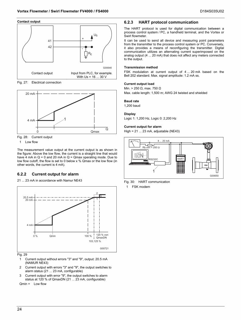
Contact output
G00646
41+
-
RE
US
42
Contact output Input from PLC, for example.
With Us = 16 ... 30 V
Fig. 27: Electrical connection
20 mA
4 mA
0 QmaxQ
1
Fig. 28: Current output
1 Low flow The measurement value output at the current output is as shown in the figure: Above the low flow, the current is a straight line that would have 4 mA in Q = 0 and 20 mA in Q = Qmax operating mode. Due to low flow cutoff, the flow is set to 0 below x % Qmax or the low flow (in other words, the current is 4 mA).
6.2.2 Current output for alarm
21 ... 23 mA in accordance with Namur NE43
G00721
1
23
20 mA
4 mA
0 % Qmin120 % vonQmaxDN
20,5 mA
100 %
103,125 %
Fig. 29
1 Current output without errors "3" and "9", output: 20.5 mA (NAMUR NE43)
2 Current output with errors "3" and "9", the output switches to alarm status (21 ... 23 mA, configurable)
3 Current output with error "9", the output switches to alarm status at 120 % of QmaxDN (21 ... 23 mA, configurable)
Qmin = Low flow
6.2.3 HART protocol communication
The HART protocol is used for digital communication between a process control system / PC, a handheld terminal, and the Vortex or Swirl flowmeter. It can be used to send all device and measuring point parameters from the transmitter to the process control system or PC. Conversely, it also provides a means of reconfiguring the transmitter. Digital communication utilizes an alternating current superimposed on the analog output (4 ... 20 mA) that does not affect any meters connected to the output. Transmission method FSK modulation at current output of 4 ... 20 mA based on the Bell 202 standard. Max. signal amplitude: 1.2 mA ss. Current output load Min. > 250 Ω, max. 750 Ω Max. cable length: 1,500 m; AWG 24 twisted and shielded Baud rate 1,200 baud Display Logic 1: 1,200 Hz, Logic 0: 2,200 Hz Current output for alarm High = 21 ... 23 mA, adjustable (NE43)
G00650
HART
4 ... 20 mA
Rb min = 250 Ω
RS232C
1
Fig. 30: HART communication
1 FSK modem
Vortex Flowmeter / Swirl Flowmeter FV4000 / FS4000 D184S035U02
25
6.3 PROFIBUS PA A
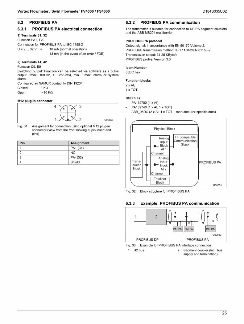
6.3.1 PROFIBUS PA electrical connection
1) Terminals 31, 32 Function PA+, PA- Connection for PROFIBUS PA to IEC 1158-2 U = 9 ... 32 V, I = 10 mA (normal operation)
13 mA (in the event of an error / FDE) 2) Terminals 41, 42 Function C9, E9 Switching output: Function can be selected via software as a pulse output (fmax: 100 Hz, 1 ... 256 ms), min. / max. alarm or system alarm. Configured as NAMUR contact to DIN 19234. Closed: 1 KΩ Open: > 10 KΩ M12 plug-in connector
G00653
4
1
3
2 Fig. 31: Assignment for connection using optional M12 plug-in
connector (view from the front looking at pin insert and pins)
Pin Assignment 1 PA+ (31) 2 NC 3 PA- (32) 4 Shield
6.3.2 PROFIBUS PA communication
The transmitter is suitable for connection to DP/PA segment couplers and the ABB MB204 multibarrier. PROFIBUS PA protocol Output signal: in accordance with EN 50170 Volume 2, PROFIBUS transmission method: IEC 1158-2/EN 61158-2 Transmission speed: 31.25 KByte/s PROFIBUS profile: Version 3.0 Ident Number 05DC hex Function blocks 2 x AI, 1 x TOT GSD files - PA139700 (1 x AI) - PA139740 (1 x AI, 1 x TOT) - ABB_05DC (2 x AI, 1 x TOT + manufacturer-specific data)
G00651
Physical Block
Trans-ducerBlock
TotalizerBlock
AnalogInputBlockAI 1
Channel
AnalogInputBlockAI 2
FF compatibleCommunication
Stack
PROFIBUS PA
Channel
Fig. 32: Block structure for PROFIBUS PA
6.3.3 Example: PROFIBUS PA communication
G00660
PA+ PA-PA+ PA- PA+ PA-PA+ PA- PA+ PA-PA+ PA-
1 2
PROFIBUS DP PROFIBUS PA
Fig. 33: Example for PROFIBUS PA interface connection 1 H2 bus 2 Segment coupler (incl. bus
supply and termination)

Vortex Flowmeter / Swirl Flowmeter FV4000 / FS4000 D184S035U02
26
6.4 FOUNDATION Fieldbus A
6.4.1 FOUNDATION Fieldbus electrical connection
1) Terminals 31, 32 Function FF+, FF- Connection for FOUNDATION Fieldbus (H1) to IEC 1158-2 U = 9 ... 32 V, I = 10 mA (normal operation)
13 mA (in the event of an error / FDE) 2) Terminals 41, 42 Function C9, E9 Switching output: Function can be selected via software as a pulse output (fmax: 100 Hz, 1 ... 256 ms), min. / max. alarm or system alarm. Configured as NAMUR contact to DIN 19234. Closed: 1 KΩ Open: > 10 KΩ
6.4.2 FOUNDATION Fieldbus communication
The transmitter is suitable for connection to special power supply units, a linking device, and the ABB MB204 multibarrier. FOUNDATION Fieldbus protocol Output signal: in accordance with the FOUNDATION Fieldbus protocol Specification: 1.4 / ITK 4.01 for the H1 bus Transmission method: IEC 1158-2 / EN 61158-2 Transmission speed: 31.25 KByte/s Manufacturer ID: 0x000320 Device ID: 0x0015 Reg. number: IT013600 Function blocks 2 x analog inputs Stack With LAS functionality
G00661
Resource Block
Trans-ducerBlock
AnalogInputBlockAI 1
Channel
AnalogInputBlockAI 2
FF compatibleCommunication
Stack
FOUNDATIONFieldbus
Channel
Fig. 34: Block structure for FOUNDATION Fieldbus The channel selector can be used to select the initial variable (volume / mass / standard flow, counter or temperature).
6.4.3 Example: FOUNDATION Fieldbus communication
G00665
1 2
FF+ FF- FF+ FF- FF+ FF-
Ethernet FOUNDATION Fieldbus
Fig. 35: Example for FOUNDATION Fieldbus interface connection 1 HSE bus
2 Linking device (incl. bus supply and termination)
Change from one to two columns

Vortex Flowmeter / Swirl Flowmeter FV4000 / FS4000 D184S035U02
27
7 Ex relevant specifications for transmitter Change from one to two columns
7.1 Ex "ib" / Ex "n" design for VT41/ST41 and VR41/SR41 (4 ... 20 mA / HART)
Important The devices may only be operated in explosive areas if the housing covers have been fully closed.
EC type-examination certificate TÜV 08 ATEX 554808 X Designation:
II 2G Ex ib IIC T4 II 2D Ex tD A21 T85°C...Tmedium IP67
Declaration of conformity TÜV 08 ATEX 554833 X Designation:
II 3G Ex nA [nL] IIC T4 II 3D Ex tD A22 T85°C...Tmedium IP67
Certificate of conformity IECEx TUN 07.0014 X Designation:
Ex ib IIC T4...T1 Ex nA [nL] IIC T4...T1 Ex tD A21 IP6X TX°C
G00668
1
2 3
UU
mm
+ ++ +8182838485868687
42 4241 4132 3231 31
VR41 / SR41
VT41 / ST41
Ex ib
Ex nA [nL]
Ex ib
Ex nA [nL]
Ex ib
Ex nA [nL]
PA
1)
1)
=6
0V
=6
0V 2)
2)
PA PA
Fig. 36: Electrical connection for VT41 / ST41 and VR41 / SR41
1 Flowmeter sensor 2 Transmitter
3 Flowmeter
Flowmeter sensor wire colors
Terminal Wire color 81 Red 82 Blue 83 Pink 84 Gray 85 Yellow 86 Green 86 Brown 87 White
1) Supply power terminals 31 / 32 a) Ex ib: Ui = 28 V DC b) Ex nA [nL] UB = 14 … 46 V DC
2) Switching output, terminals 41/ 42 The switching output (passive) optocoupler is designed as a NAMUR contact (to DIN 19234). When the contact is closed, the internal resistance is approx. 1,000 Ω. When the contact is open, it is > 10 KΩ. The switching output can be changed over to "optocoupler" if required. a) NAMUR with switching amplifier b) Switching output (optocoupler) - Ex ib: Ui = 15 V - Ex nA [nL]: UB = 16 … 30 V
IB = 2 … 15 mA
Important The installation instructions in accordance with EN 60079-14 must be complied with. When commissioning the flowmeter, refer to EN 50281-1-2 regarding use in areas with combustible dust. After switching off the supply power, wait t > 2 minutes before opening the transmitter housing.
7.1.1 Supply power or supply current
G00670
1,81,6
1,41,2
1
010 14 28 4820 30
Ex ib
Ex nA [nL]
40 50
US
[V]
0,8
0,6
0,4
0,2
BR
[K]
Ω
Fig. 37 The minimum voltage US of 14 V is based on a load of 0 Ω. US = supply voltage RB = Maximum permissible load in power supply circuit, e.g.,
indicator, recorder or power resistor

Vortex Flowmeter / Swirl Flowmeter FV4000 / FS4000 D184S035U02
28
7.1.2 Approval data for hazardous areas Power supply circuit
Terminals 31, 32
Zone 1: Ex ib IIC Tamb = (-40 °C) -20 ... 70 °C Ui = 28 V Ii = 110 mA Pi = 770 mW Effective internal capacitance: 14.6 nF Effective internal capacitance to ground: 24.4 nF Effective internal inductance: 0.27 mH Zone 2: Ex nA [nL] IIC Tamb = (-40 °C) -20 ... 70 °C UB = 14 … 46 V
Type of protection Um = 60 V
Zone 21 / 22: Ex tD A21 / Ex tD A22 Tamb = -20 °C ... 60 °C
Power supply circuit
Terminals 41, 42
Zone 1: Ex ib IIC Ui = 15 V Ii = 30 mA Pi = 115 mW Effective internal capacitance: 11 nF Effective internal capacitance to ground: 19.6 nF Effective internal inductance: 0.14 mH Zone 2: Ex nA [nL] IIC UB = 16 … 30 V IB = 2 … 15 mA
Type of protection Um = 60 V
Zone 21 / 22: Ex tD A21 / Ex tD A22 Tamb = -20 °C ... 60 °C
The devices must be installed in a protected environment in accordance with the specific conditions on the test certificate. Pollution degree 3 (see IEC 60664-1) must not be exceeded for the macro environment of the device. The devices conform to degree of protection IP 65 / IP 67. If the device is installed as intended, this requirement is met by the housing as standard. When connected to the line supply / not connected to the line supply, the electrical circuits must not exceed overvoltage category III / II.
7.1.3 Medium temperatures / Temperature classes
For the supply circuit "Terminals 31, 32" and the switching outputs "Terminals 41, 42", cables suitable for temperatures up to T = 110 °C (T = 230 °F) can be used without restriction. Category 2/3G For cables suitable only for temperatures up to T= 80 °C (T = 176 °F), the interconnection of both circuits needs to be taken into account in the event of a fault. Otherwise, the restricted temperature ranges listed in the following table shall apply. Category 2D For cables suitable only for temperatures up to T= 80 °C (T = 176 °F), the restricted temperature ranges listed in the following table shall apply.
Ambient temperature 2)
Max. temperature at used connecting cable, "Terminals 31, 32", "Terminals 41, 42"
Max. permissible medium temperature
(-40) -20 ... 70 °C 3) ((-40) -4 ... 158 °F) 3)
110 °C (230 °F) 280 °C / 400 °C 1) (536 °F / 752 °F) 1)
(-40) -20 ... 70 °C 3) ((-40) -4 ... 158 °F) 3)
160 °C (320 °F)
(-40) -20 ... 60 °C ((-40) -4 ... 140 °F)
240 °C (464 °F)
(-40) -20 ... 55 °C ((-40) -4 ... 131 °F)
280 °C (536 °F)
(-40) -20 ... 50 °C ((-40) -4 ... 122 °F)
320 °C (608 °F) 1)
(-40) -20 ... 40 °C ((-40) -4 ... 104 °F)
80 °C (176 °F)
400 °C (752 °F) 1)
1) Medium temperatures > 280 °C (> 536 °F) with FV4000 Vortex flowmeter only 2) The permissible limits for the ambient temperature are approval- and order-specific
(standard: -20 °C (-4 °F)). 3) Category 2D (dust-ignition proof) maximum 60° C (140° F)
Maximum medium temperature
Temperature class
130 °C (266 °F) T4 195 °C (383 °F) T3 290 °C (554 °F) T2 400 °C (752 °F) T1
Change from one to two columns

Vortex Flowmeter / Swirl Flowmeter FV4000 / FS4000 D184S035U02
29
Change from one to two columns
7.2 Ex "d" / Ex "ib" / Ex "n" design for VT42/ST42 and VR42/SR42 (4 ... 20 mA / HART)
Important The devices may only be operated in explosive areas if the housing covers have been fully closed.
EC type-examination certificate TÜV 08 ATEX 554955 X Designation • Transmitter / Flowmeter
II 2G Ex d [ib] IIC T6 II 2G Ex ib IIC T4 II 2D Ex tD A21 T 85 °C ... Tmed IP 67
• Flowmeter sensor
II 2G Ex ib IIC T4 II 2D Ex tD A21 T 85 °C ... Tmed IP 67
Declaration of conformity TÜV 08 ATEX 554956 X Designation on sensor / transmitter / flowmeter
II 3G Ex nA [nL] IIC T4 II 3D Ex tD A22 T85°C...Tmed IP 67
Certificate of conformity IECEx TUN 08.0010 X Designation:
Ex d [ib] IIC T6 to T1 Ex ib IIC T4 to T1 Ex tD A21 IP6X T85°C...Tmedium Ex nA [nL] IIC T4 to T1
G00673
Eex d [ib]
Ex ib
Ex nA [L]
1
2 3
UU
mm
+ ++ +
8182838485868687
42 4241 4132 3231 31
VR42/SR42
VT42/ST42
Ex d [ib]
Ex ib
Ex nA [nL]
Ex ib
Ex nA [nL]
PA
1)
1)
=6
0V
=6
0V 2)
2)
PA PA
Ex d [ib]
Ex ib
Ex nA [nL]
Fig. 38: Electrical connection for VT42 / ST42 and VR42 / SR42
1 Flowmeter sensor 2 Transmitter
3 Flowmeter
Flowmeter sensor wire colors
Terminal Wire color 81 Red
82 Blue
83 Pink
84 Gray
85 Yellow
86 Green
86 Brown
87 White
1) Supply power terminals 31 / 32
a) Ex ib: Ui = 28 V DC b) Ex d [ib] / Ex nA [nL] UB = 14 … 46 V DC
2) Switching output, terminals 41/ 42 The switching output (passive) is designed as an optocoupler. If required, the switching output (passive) can be designed as a NAMUR contact (to DIN 19234). a) NAMUR with switching amplifier b) Switching output (optocoupler) - Ex ib: Ui = 15 V - Ex d [ib] / Ex nA [nL]: UB = 16 … 30 V
IB = 2 … 15 mA
Important Supply current (supply power) and switching output must be either only intrinsically safe or only non-intrinsically safe. A combination of the two is not permitted. On intrinsically safe circuits, equipotential bonding must be in place along the entire length of the cable used.

Vortex Flowmeter / Swirl Flowmeter FV4000 / FS4000 D184S035U02
30
7.2.1 Supply power or supply current
G00670
1,81,6
1,41,2
1
010 14 28 4820 30
Ex ib
Ex nA [nL]
40 50
US
[V]
0,8
0,6
0,4
0,2
BR
[K]
Ω
Fig. 39 The minimum voltage US of 14 V is based on a load of 0 Ω. US = supply voltage RB = Maximum permissible load in power supply circuit, e.g.,
indicator, recorder or power resistor
Important The installation instructions in accordance with EN 60079-14 must be complied with. When commissioning the flowmeter, refer to EN 50281-1-2 regarding use in areas with combustible dust. After switching off the supply power, wait t > 2 minutes before opening the transmitter housing.
7.2.2 Approval data for hazardous areas Power supply circuit
Terminals 31, 32
Zone 1: Ex d [ib] IIC Tamb = (-40 °C) -20 ... 60 °C Zone 2: Ex nA [nL] IIC Tamb = (-40 °C) -20 ... 70 °C UB = 14 ... 46 V Zone 1: Ex ib IIC Tamb = (-40 °C) -20 ... 70 °C Ui = 28 V Ii = 110 mA Pi = 770 mW Effective internal capacitance: 14.6 nF Effective internal capacitance to ground: 24.4 nF Effective internal inductance: 0.27 mH
Type of protection Um = 60 V
Zone 21 / 22; Ex td A21 / Ex tD A22 Tamb = -20 ... 60 °C
Power supply circuit
Terminals 41, 42
Zone 1: Ex d [ib] IIC Zone 2: Ex nA [nL] IIC UB = 16 ... 30 V IB = 2 ... 15 mA Zone 1: Ex ib IIC Ui = 15 V Ii = 30 mA Pi = 115 mW Effective internal capacitance: 11.6 nF Effective internal capacitance to ground: 19.6 nF Effective internal inductance: 0.14 mH
Type of protection Um = 60 V
Zone 21 / 22: Ex td A21 / Ex td A22 Tamb = -20 ... 60 °C
When connected to the line supply / not connected to the line supply, the electrical circuits must not exceed overvoltage category III / II.

Vortex Flowmeter / Swirl Flowmeter FV4000 / FS4000 D184S035U02
31
7.2.3 Medium temperatures / Temperature classes
For the supply circuit "Terminals 31, 32" and the switching outputs "Terminals 41, 42", cables suitable for temperatures up to T = 110 °C (T = 230 °F) can be used without restriction. Category 2/3G (Ex ib IIC) For cables suitable only for temperatures up to T= 80 °C (T = 176 °F), the interconnection of both circuits needs to be taken into account in the event of a fault. Otherwise, the restricted temperature ranges listed in the following table shall apply. Category 2D For cables suitable only for temperatures up to T= 80 °C (T = 176 °F), the restricted temperature ranges listed in the following table shall apply.
Ambient temperature 2)
Max. temperature at used connecting cable, "Terminals 31, 32", "Terminals 41, 42"
Max. permissible medium temperature
(-40) -20 ... 60 °C (-40) -4 ... 140 °F)
110 °C (230 °F) 280 °C / 400 °C 1) (536 °F / 752 °F) 1)
(-40) -20 ... 60 °C (-40) -4 ... 140 °F)
240 °C (464 °F)
(-40) -20 ... 55 °C (-40) -4 ... 131 °F)
280 °C (536 °F)
(-40) -20 ... 50 °C (-40) -4 ... 122 °F)
320 °C (608 °F) 1)
(-40) -20 ... 40 °C (-40) -4 ... 104 °F)
80 °C (176 °F)
400 °C (752 °F) 1)
1) Medium temperatures > 280 °C (> 536 °F) with FV4000 Vortex flowmeter only 2) The permissible lower limits for the ambient temperature are approval- and order-
specific (standard: -20 °C (-4 °F)).
Hazardous area design
Maximum medium temperature
Temperature class
80 °C (176 °F) T6 3) Ex d [ib] IIC
95 °C (203 °F) T5 3) 130 °C (266 °F) T4 195 °C (383 °F) T3 290 °C (554 °F) T2
Ex ib IIC bzw.
Ex nA [nL] 400 °C (752 °F) T1
3) Not possible for flowmeter sensor version VR42 / SR42
7.3 FM approval design for the USA and Canada for VT43/ST43 and VR43/SR43 (4 ... 20 mA / HART)
Important The devices may only be operated in explosive areas if the housing covers have been fully closed.
Designation Explosion-proof XP/Class I/Div 1/BCD/T4 Ta = 70 °C Type 4X Dust-ignition-proof
DIP/Class II,III/Div 1/EFG/T4 Ta = 70 °C Type 4X
Intrinsic safety IS/Class I, II,III/Div 1/ABCDEFG/T4 Ta = 70 °C Entity Type 4X
Non-incendive NI/Class I/Div 2/ABCD/T4 Ta = 70 °C Type 4X Suitable S/Class II,III/Div 2/FG/T4 Ta = 70 °C Type 4X
The devices must be installed in a protected environment in accordance with the specific conditions on the test certificate. Pollution degree 3 (see IEC 60664-1) must not be exceeded for the macro environment of the device. The devices conform to degree of protection IP 65 / IP 67. If the device is installed as intended, this requirement is met by the housing as standard. When connected to the line supply / not connected to the line supply, the electrical circuits must not exceed overvoltage category III / II. IS Entity see: SD-50-2681 (Fig. 35) Parameters: Vmax, Imax, Pi, Li, Ci Enclosure: Type 4X
G00674
Eex d [ib]
Ex ib
Ex nA [L]
FM
APPROVEDC US
FM
APPROVEDC US
FM
APPROVEDC US
1
2 3
+ ++ +
8182838485868687
42 4241 4132 3231 31
VR43/SR43
VT43/ST43
PA
PA PA
Fig. 40: Electrical connection for VT43 / ST43 and VR43 / SR43 1 Flowmeter sensor 2 Transmitter
3 Flowmeter
Flowmeter sensor wire colors
Terminal Wire color 81 Red 82 Blue 83 Pink 84 Gray 85 Yellow 86 Green 86 Brown 87 White

Vortex Flowmeter / Swirl Flowmeter FV4000 / FS4000 D184S035U02
32
7.3.1 Supply power or supply current
G00707
1,81,6
1,41,2
1
010 14 28 4820 30
IS
XP, DIP, NI, S
40 50
US
[V]
0,8
0,6
0,4
0,2
BR
[K]
Ω
Fig. 41 The minimum voltage US of 14 V is based on a load of 0 Ω. US = supply voltage RB = Maximum permissible load in power supply circuit, e.g.,
indicator, recorder or power resistor
7.3.2 Medium temperatures / Temperature classes
For the supply circuit "Terminals 31, 32" and the switching outputs "Terminals 41, 42", cables suitable for temperatures up to T = 110 °C (T = 230 °F) can be used without restriction. For cables suitable only for temperatures up to T= 80 °C (T = 176 °F), the restricted temperature ranges listed in the following table shall apply.
Ambient temperature
Max. temperature at used connecting cable, "Terminals 31, 32", "Terminals 41, 42"
Max. permissible medium temperature
(-45) -20 ... 60 °C (-49) -4 ... 140 °F)
110 °C (230 °F) 280 °C / 400 °C 1) (536 °C / 752 °F) 1)
(-45) -20 ... 60 °C (-49) -4 ... 140 °F)
240 °C (464 °F)
(-45) -20 ... 55 °C (-49) -4 ... 131 °F)
280 °C (536 °F)
(-45) -20 ... 50 °C (-49) -4 ... 122 °F)
320 °C (608 °F) 1)
(-45) -20 ... 40 °C (-49) -4 ... 104 °F)
80 °C (176 °F)
400 °C (752 °F) 1)
1) Medium temperatures > 280 °C (> 536 °F) with VT43 / VR43 Vortex flowmeter only
Change from one to two columns
7.3.3 Approval data for hazardous areas
Supply circuit terminals 31, 32 Explosion-proof XP/Class I/Div 1/BCD/T4 Ta = 70 °C Type 4X
Dust-ignition-proof DIP/Class II,III/Div 1/EFG/T4 Ta = 70 °C Type 4X DIP/Class II,III /Div 2 /EFG /T4 Ta=70°C Type 4X
UB = 14 ... 46 V
Intrinsic safety IS/Class I, II,III/Div 1 ABCDEFG/T4 Ta = 70 °C Entity Type 4X
Vmax = 28 V Imax = 110 mA Pi = 770 mW Effective internal capacitance: 14.6 nF Effective internal inductance: 0.27 mH
Non-incendive NI/Class I/Div 2/ABCD/T4 Ta = 70 °C Type 4X UB = 14 ... 46 V Supply circuit terminals 41, 42
Explosion-proof XP/Class I/Div 1/BCD/T4 Ta = 70 °C Type 4X
Dust-ignition-proof DIP/Class II,III/Div 1/EFG/T4 Ta = 70 °C Type 4X DIP/Class II,III /Div 2 /EFG /T4 Ta=70°C Type 4X
UB = 16 ... 30 V IB = 2 ... 15 mA
Intrinsic safety IS/Class I, II,III/Div 1 ABCDEFG/T4 Ta = 70 °C Entity Type 4X
Vmax = 15 V Imax = 30 mA Pi = 115 mW Effective internal capacitance: 11 nF Effective internal inductance: 0.14 mH
Non-incendive NI/Class I/Div 2/ABCD/T4 Ta = 70 °C Type 4X UB = 16 ... 30 V IB = 2 ... 15 mA

Vortex Flowmeter / Swirl Flowmeter FV4000 / FS4000 D184S035U02
33
7.3.4 Trio-Wirl control drawing
Fig. 42: Electrical connection and connection data, VT43 / VR43 and ST43 / SR43

Vortex Flowmeter / Swirl Flowmeter FV4000 / FS4000 D184S035U02
34
Change from one to two columns
7.4 EEX "ia" design for VT4A/ST4A and VR4A/SR4A (fieldbus)
Important The devices may only be operated in explosive areas if the housing covers have been fully closed.
EC type-examination test certificate TÜV 01 ATEX 1771 Designation II 2G EEx ia IIC T4 II 2D T85 °C ... Tmed IP 67 The hazardous area design is based on the PTB's FISCO model (FISCO = fieldbus intrinsically safe concept).
G00675
81
82
83
84
85
86
86
87
VR4A/SR4A
42
41
32
31
E9
C9
FF-
FF+
E9
C9
PA-
PA+
b) a)
1)
2)
42
41
32
31
E9
C9
FF-
FF+
E9
C9
PA-
PA+
b) a)
VT4A/ST4A
1)
2)1
2
3
4
44
Fig. 43: Electrical connection for PROFIBUS PA interface
connection 1 Flowmeter 2 Flowmeter sensor
3 Transmitter 4 Functional ground
Flowmeter sensor wire colors
Terminal Wire color 81 Red 82 Blue 83 Pink 84 Gray 85 Yellow 86 Green 86 Brown 87 White
A
7.4.1 PROFIBUS PA electrical connection
1) Terminals 31, 32 Function PA+, PA- Connection for PROFIBUS PA to IEC 1158-2 U = 9 ... 32 V, I = 10 mA (normal operation)
13 mA (in the event of an error / FDE) 2) Terminals 41, 42 Function C9, E9 Switching output: Function can be selected via software as a pulse output (fmax: 100 Hz, 1 ... 256 ms), min. / max. alarm or system alarm. Configured as NAMUR contact to DIN 19234. Closed: 1 KΩ Open: > 10 KΩ M12 plug-in connector
G00653
4
1
3
2 Fig. 44: Assignment for connection using optional M12 plug-in
connector (view from the front looking at pin insert and pins)
Pin Assignment 1 PA+ (31) 2 NC 3 PA- (32) 4 Shield
A
7.4.2 FOUNDATION Fieldbus electrical connection
1) Terminals 31, 32 Function FF+, FF- Connection for FOUNDATION Fieldbus (H1) to IEC 1158-2 U = 9 ... 32 V, I = 10 mA (normal operation)
13 mA (in the event of an error / FDE) 2) Terminals 41, 42 Function C9, E9 Switching output: Function can be selected via software as a pulse output (fmax: 100 Hz, 1 ... 256 ms), min. / max. alarm or system alarm. Configured as NAMUR contact to DIN 19234. Closed: 1 KΩ Open: > 10 KΩ
Important The installation instructions in accordance with EN 60079-14 must be complied with. When commissioning the flowmeter, refer to EN 50281-1-2 regarding use in areas with combustible dust. After switching off the supply power, wait t > 2 minutes before opening the transmitter housing.
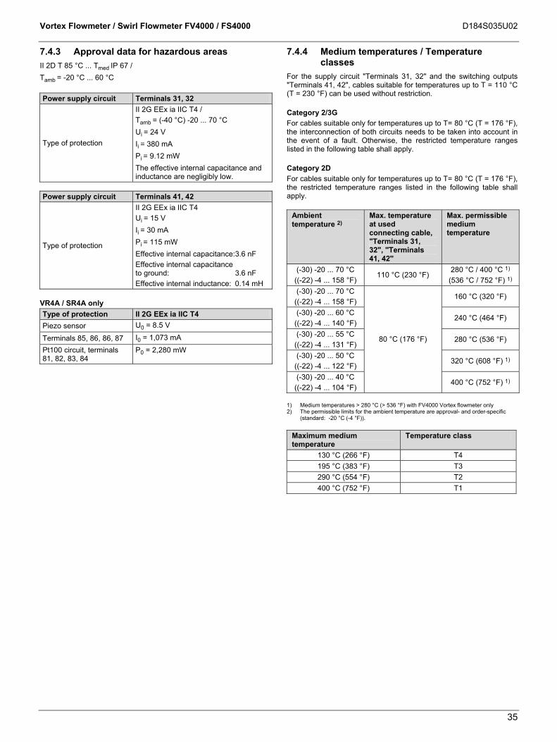
Vortex Flowmeter / Swirl Flowmeter FV4000 / FS4000 D184S035U02
35
7.4.3 Approval data for hazardous areas
II 2D T 85 °C ... Tmed IP 67 / Tamb = -20 °C ... 60 °C Power supply circuit Terminals 31, 32
Type of protection
II 2G EEx ia IIC T4 / Tamb = (-40 °C) -20 ... 70 °C Ui = 24 V Ii = 380 mA Pi = 9.12 mW The effective internal capacitance and inductance are negligibly low.
Power supply circuit Terminals 41, 42
Type of protection
II 2G EEx ia IIC T4 Ui = 15 V Ii = 30 mA Pi = 115 mW Effective internal capacitance: 3.6 nF Effective internal capacitance to ground: 3.6 nF Effective internal inductance: 0.14 mH
VR4A / SR4A only Type of protection II 2G EEx ia IIC T4 Piezo sensor U0 = 8.5 V
Terminals 85, 86, 86, 87 I0 = 1,073 mA Pt100 circuit, terminals 81, 82, 83, 84
P0 = 2,280 mW
7.4.4 Medium temperatures / Temperature classes
For the supply circuit "Terminals 31, 32" and the switching outputs "Terminals 41, 42", cables suitable for temperatures up to T = 110 °C (T = 230 °F) can be used without restriction. Category 2/3G For cables suitable only for temperatures up to T= 80 °C (T = 176 °F), the interconnection of both circuits needs to be taken into account in the event of a fault. Otherwise, the restricted temperature ranges listed in the following table shall apply. Category 2D For cables suitable only for temperatures up to T= 80 °C (T = 176 °F), the restricted temperature ranges listed in the following table shall apply.
Ambient temperature 2)
Max. temperature at used connecting cable, "Terminals 31, 32", "Terminals 41, 42"
Max. permissible medium temperature
(-30) -20 ... 70 °C ((-22) -4 ... 158 °F)
110 °C (230 °F) 280 °C / 400 °C 1) (536 °C / 752 °F) 1)
(-30) -20 ... 70 °C ((-22) -4 ... 158 °F)
160 °C (320 °F)
(-30) -20 ... 60 °C ((-22) -4 ... 140 °F)
240 °C (464 °F)
(-30) -20 ... 55 °C ((-22) -4 ... 131 °F)
280 °C (536 °F)
(-30) -20 ... 50 °C ((-22) -4 ... 122 °F)
320 °C (608 °F) 1)
(-30) -20 ... 40 °C ((-22) -4 ... 104 °F)
80 °C (176 °F)
400 °C (752 °F) 1)
1) Medium temperatures > 280 °C (> 536 °F) with FV4000 Vortex flowmeter only 2) The permissible limits for the ambient temperature are approval- and order-specific
(standard: -20 °C (-4 °F)).
Maximum medium temperature
Temperature class
130 °C (266 °F) T4 195 °C (383 °F) T3 290 °C (554 °F) T2 400 °C (752 °F) T1
Change from one to two columns
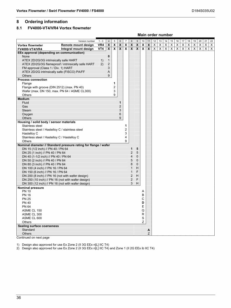
Vortex Flowmeter / Swirl Flowmeter FV4000 / FS4000 D184S035U02
36
Bestellangaben
8 Ordering information
8.1 FV4000-VT4/VR4 Vortex flowmeter
Main order number
Version number 1 - 3 4 5 6 7 8 9 10 11 12 13 14 15 16 17 18 19 20 21 22
Vortex flowmeter Remote mount design VR4 X X X X X X X X X X X X X X X X X X X FV4000-VT4/VR4 Integral mount design VT4 X X X X X X X X X X X X X X X X X X X EEx approval (depending on communication)
None 0 ATEX 2D/2G/3G intrinsically safe HART 1) 1 ATEX 2D/2G/3G flameproof / intrinsically safe HART 2) 2 FM approval (Class 1 / Div. 1) HART 3 ATEX 2D/2G intrinsically safe (FISCO) PA/FF A Others 9 Process connection
Flange 1 Flange with groove (DIN 2512) (max. PN 40) 2 Wafer (max. DN 150, max. PN 64 / ASME CL300) 3 Others 9 Medium
Fluid 1 Gas 2 Steam 3 Oxygen 6 Others 9 Housing / solid body / sensor materials
Stainless steel 1 Stainless steel / Hastelloy C / stainless steel 2 Hastelloy C 3 Stainless steel / Hastelloy C / Hastelloy C 4 Others 9 Nominal diameter // Standard pressure rating for flange / wafer
DN 15 (1/2 inch) // PN 40 / PN 64 1 5 DN 25 (1 inch) // PN 40 / PN 64 2 5 DN 40 (1-1/2 inch) // PN 40 / PN 64 4 0 DN 50 (2 inch) // PN 40 / PN 64 5 0 DN 80 (3 inch) // PN 40 / PN 64 8 0 DN 100 (4 inch) // PN 16 / PN 64 1 H DN 150 (6 inch) // PN 16 / PN 64 1 F DN 200 (8 inch) // PN 16 (not with wafer design) 2 H DN 250 (10 inch) // PN 16 (not with wafer design) 2 F DN 300 (12 inch) // PN 16 (not with wafer design) 3 H Nominal pressure
PN 10 A PN 16 B PN 25 C PN 40 D PN 64 E ASME CL 150 Q ASME CL 300 R ASME CL 600 S Others Z Sealing surface coarseness
Standard A Others Z Continued on next page 1) Design also approved for use Ex Zone 2 (II 3G EEx n[L] IIC T4) 2) Design also approved for use Ex Zone 2 (II 3G EEx n[L] IIC T4) and Zone 1 (II 2G EEx ib IIC T4)

Vortex Flowmeter / Swirl Flowmeter FV4000 / FS4000 D184S035U02
37
Continued Main order number
Version number 1 - 3 4 5 6 7 8 9 10 11 12 13 14 15 16 17 18 19 20 21 22
Vortex flowmeter Remote mount design VR4 X X X X X X X X X X X X X X X X X X X FV4000-VT4/VR4 Integral mount design VT4 X X X X X X X X X X X X X X X X X X X Sensor design
Standard single sensor (Tmax = 280 °C) 1 Standard single sensor with integrated temperature sensor 2 Double sensor (Tmax = 280 °C) 3 Double sensor (Tmax = 280 °C) with integrated temperature sensor 4 High temperature (< 400 °C) single sensor A Others Z
Temperature range, medium / seals Graphite -55 … 280 °C (max. PN 64 / ASME CL 300) 1 Graphite special -55 ... 400 °C (max. PN 64 / ASME CL 300) (for high-temperature sensor only)
2
Kalrez (3018) O-ring 0 ... 280 °C 3 Viton O-ring -55 ... 230 °C (not for steam) 4 PTFE O-ring -55 ... 200 °C 5 Kalrez (6375) O-ring -20 ... 275 °C 8
Certificates None A Acceptance test certificate EN 10204-3.1 B Material certificate 3.1 to EN 10204 and pressure test to AD-2000 C Pressure test to AD-2000 D
Communication With display with HART 2 With display with PROFIBUS PA 4 With display with FOUNDATION Fieldbus 6 Others 9
Name plate German G English E French F
Design level / Software version (Specified by ABB) x
Additional equipment None 0 Climate-proof design 2
Operating mode Continuous flow A
Cable gland M20 x 1.5 (not for EEx approval Code 2 or 3) A 1/2 inch NPT B M12 plug connector (only for communication Code 4 and EEx approval Code 0 or A) 3) C Others Z
Calibration Test log 4) A Calibration log 5) B Others Z
Ambient temperature range -20 ... 70 °C (standard for EEx approval Code 0, 1, 3, or A) 1 -55 ... 70 °C (extended temperature range for EEx approval Code 0) 2 -20 ... 60 °C (standard for EEx approval Code 2) 3 -40 ... 60 °C (extended temperature range for EEx approval Code 2) 4 -40 ... 70 °C (extended temperature range for EEx approval Code 1) 5 -45 ... 70 °C (extended temperature range for EEx approval Code 3) 6 -30 ... 70 °C (extended temperature range for EEx approval Code A) 7
3) NPE300-NE socket not included in scope of delivery. Please order this separately if required (part no. 9890116). 4) Test log with k factors 5) Calibration log with k factors and error curve

Vortex Flowmeter / Swirl Flowmeter FV4000 / FS4000 D184S035U02
38
8.2 FS4000-ST4/SR4 Swirl flowmeter
Main order number
Version number 1 - 3 4 5 6 7 8 9 10 11 12 13 14 15 16 17 18 19 20 21 22
Swirl flowmeter Remote mount design SR4 X X X X X X X X X X X X X X X X X X X FS4000-ST4/SR4 Integral mount design ST4 X X X X X X X X X X X X X X X X X X X EEx approval
None 0 ATEX 2D/2G/3G intrinsically safe HART 1) 1 ATEX 2D/2G/3G flameproof / intrinsically safe HART 2) 2 FM approval (Class 1 / Div. 1) HART 3 ATEX 2D/2G intrinsically safe (FISCO) PA/FF A Others 9 Process connection
Flange 1) 1 Flange with groove (DIN 2512) 2) 2 Others 9 Medium
Fluid 1 Gas 2 Steam 3 Oxygen 3) 6 Others 9 Housing // inlet / outlet pipe // sensor materials
Stainless steel 1 Stainless steel / Hastelloy C / stainless steel 2 Hastelloy C 3 Stainless steel / Hastelloy C / Hastelloy C 4 Others 9 Nominal diameter / Standard pressure rating
DN 15 (1/2 inch) / PN 40 1 5 DN 20 (3/4 inch) / PN 40 2 0 DN 25 (1 inch) / PN 40 2 5 DN 32 (1-1/4 inch) / PN 40 3 2 DN 40 (1-1/2 inch) / PN 40 4 0 DN 50 (2 inch) / PN 40 5 0 DN 80 (3 inch) / PN 40 8 0 DN 100 (4 inch) / PN 16 1 H DN 150 (6 inch) / PN 16 1 F DN 200 (8 inch) / PN 16 2 H DN 300 (12 inch) / PN 16 3 H DN 400 (16 inch) / PN 16 4 H Nominal pressure
PN 10 A PN 16 B PN 25 (only DN 200) C PN 40 (max. DN 200) D ASME CL 150 Q ASME CL 300 (max. DN 200) R Others Z Sealing surface coarseness
Standard A Others Z Continued on next page 1) Design also approved for use Ex Zone 2 (II 3G EEx n[L] IIC T4) 2) Design also approved for use Ex Zone 2 (II 3G EEx n[L] IIC T4) and Zone 1 (II 2G EEx ib IIC T4) 3) Flowmeter sensor for oxygen use, cleaned and labeled

Vortex Flowmeter / Swirl Flowmeter FV4000 / FS4000 D184S035U02
39
Continued Main order number
Version number 1 - 3 4 5 6 7 8 9 10 11 12 13 14 15 16 17 18 19 20 21 22
Swirl flowmeter Remote mount design SR4 X X X X X X X X X X X X X X X X X X X FS4000-ST4/SR4 Integral mount design ST4 X X X X X X X X X X X X X X X X X X X Sensor design
Standard single sensor (Tmax = 280 °C) 1 Standard single sensor with integrated temperature sensor 2 Double sensor (Tmax = 280 °C) (min. DN 50) 3 Double sensor (Tmax = 280 °C) with integrated temperature sensor (min. DN 50) 4 Others Z
Temperature range, medium / seals Graphite -55 … 280 °C 1 Kalrez (3018) O-ring 0 ... 280 °C 3 Viton O-ring -55 ... 230 °C (not for steam) 4 PTFE O-ring 5 Kalrez (6375) O-ring 8
Certificates None A Acceptance test certificate EN 10204-3.1 B Material certificate 3.1 to EN 10204 and pressure test to AD-2000 C Pressure test to AD-2000 D
Communication With display with HART 2 With display with PROFIBUS PA 4 With display with FOUNDATION Fieldbus 6 Others 9
Name plate German G English E French F
Design level / Software version (Specified by ABB) x
Additional equipment None 0 Climate-proof design 2
Operating mode Continuous flow A
Cable gland M20 x 1.5 (not for EEx approval Code 2 or 3) A 1/2 inch NPT B M12 plug connector (only for communication Code 4 and EEx approval Code 0 or A) 4) C Others Z
Calibration Test log 5) A Calibration log 6) B Gas / fluid test log 5) C Gas / fluid calibration log 6) D Others Z
Ambient temperature range -20 ... 70 °C (standard for EEx approval Code 0, 1, 3, or A) 1 -55 ... 70 °C (extended temperature range for EEx approval Code 0) 2 -20 ... 60 °C (standard for EEx approval Code 2) 3 -40 ... 60 °C (extended temperature range for EEx approval Code 2) 4 -40 ... 70 °C (extended temperature range for EEx approval Code 1) 5 -45 ... 70 °C (extended temperature range for EEx approval Code 3) 6 -30 ... 70 °C (extended temperature range for EEx approval Code A) 7
4) NPE300-NE socket not included in scope of delivery. Please order this separately if required (part no. 9890116). 5) Test log with k factors 6) Calibration log with k factors and error curve
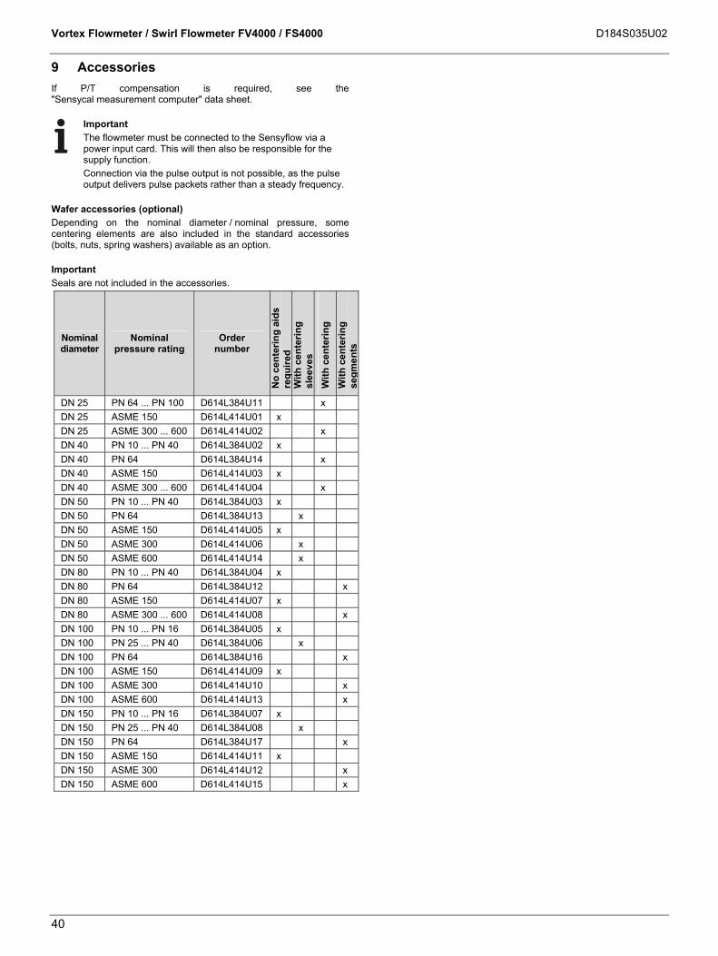
Vortex Flowmeter / Swirl Flowmeter FV4000 / FS4000 D184S035U02
40
9 Accessories Change from one to two columns
If P/T compensation is required, see the "Sensycal measurement computer" data sheet.
Important The flowmeter must be connected to the Sensyflow via a power input card. This will then also be responsible for the supply function. Connection via the pulse output is not possible, as the pulse output delivers pulse packets rather than a steady frequency.
Wafer accessories (optional) Depending on the nominal diameter / nominal pressure, some centering elements are also included in the standard accessories (bolts, nuts, spring washers) available as an option. Important Seals are not included in the accessories.
Nominal diameter
Nominal pressure rating
Order number
No
cent
erin
g ai
ds
requ
ired
With
cen
terin
g sl
eeve
s W
ith c
ente
ring
With
cen
terin
g se
gmen
ts
DN 25 PN 64 ... PN 100 D614L384U11 x DN 25 ASME 150 D614L414U01 x DN 25 ASME 300 ... 600 D614L414U02 x DN 40 PN 10 ... PN 40 D614L384U02 x DN 40 PN 64 D614L384U14 x DN 40 ASME 150 D614L414U03 x DN 40 ASME 300 ... 600 D614L414U04 x DN 50 PN 10 ... PN 40 D614L384U03 x DN 50 PN 64 D614L384U13 x DN 50 ASME 150 D614L414U05 x DN 50 ASME 300 D614L414U06 x DN 50 ASME 600 D614L414U14 x DN 80 PN 10 ... PN 40 D614L384U04 x DN 80 PN 64 D614L384U12 x DN 80 ASME 150 D614L414U07 x DN 80 ASME 300 ... 600 D614L414U08 x DN 100 PN 10 ... PN 16 D614L384U05 x DN 100 PN 25 ... PN 40 D614L384U06 x DN 100 PN 64 D614L384U16 x DN 100 ASME 150 D614L414U09 x DN 100 ASME 300 D614L414U10 x DN 100 ASME 600 D614L414U13 x DN 150 PN 10 ... PN 16 D614L384U07 x DN 150 PN 25 ... PN 40 D614L384U08 x DN 150 PN 64 D614L384U17 x DN 150 ASME 150 D614L414U11 x DN 150 ASME 300 D614L414U12 x DN 150 ASME 600 D614L414U15 x
Change from one to two columns

Vortex Flowmeter / Swirl Flowmeter FV4000 / FS4000 D184S035U02
41
10 Questionnaire
Customer:
Date:
Ms./Mr.:
Department:
Phone:
Fax:
Measuring system: FV4000 Vortex flowmeter FS400 Swirl flowmeter
Integrated Pt100 (for measuring media temperature recording or saturated steam mass calculation)
Fluid: Oxygen Fluid Aggregate state Steam / gas
Flowrate: m3/h (min., max., operating point) US gal/min Standard condition ____________ ft3/min Mass kg/h Operating mode lb/h
Density: ____________ kg/m3 Standard condition (min., max., operating point) lb/ft3 Operating mode
Viscosity: ____________ mPas (cp) (Please specify for fluids) (min., max., operating point) cst
Fluid temperature: ____________ °C (min., max., operating point) °F
Ambient temperature: ____________ °C (min., max., operating point) °F
Pressure: ____________ bar (min., max., operating point) psi
____________ DN Nominal diameter/nominal pressure rating of the pipeline: ____________ PN
____________ mm Eff. inside diameter of the pipeline: inch
Transmitter design / communication:
4 ... 20 mA (2-wire) HART (standard)
2-wire PROFIBUS PA
2-wire FOUNDATION Fieldbus
Explosion protection Without 2G Ex "ib" 2G Ex "d" 3G Ex "nA [L]"
Explosion protection Without 2G Ex "ia"
Explosion protection Without 2G EEx "ia"
A

Contact us
D18
4S03
5U02
Rev
.10
12.2
010ABB Ltd.
Oldends Lane, Stonehouse Gloucestershire, GL10 3TA UK Phone: +44 (0)1453 826661 Fax: +44 (0)1453 829671 ABB Inc. 125 E. County Line Road Warminster PA 18974 USA Phone: +1 215 674 6000 Fax: +1 215 674 7183 ABB Automation Products GmbH Dransfelder Str. 2 37079 Goettingen Germany Phone: +49 551 905-534 Fax: +49 551 905-555 www.abb.com
Note We reserve the right to make technical changes or modify the contents of this document without prior notice. With regard to purchase orders, the agreed particulars shall prevail. ABB does not accept any responsibility whatsoever for potential errors or possible lack of information in this document. We reserve all rights in this document and in the subject matter and illustrations contained therein. Any reproduction, disclosure to third parties or utilization of its contents - in whole or in parts – is forbidden without prior written consent of ABB. Copyright© 2010 ABB All rights reserved