data sheet part no. : l-517hurd-f rev : a /...
TRANSCRIPT

PARA LIGHT ELECTRONICS CO., LTD. 4F, No.1, Lane 93, Chien Yi Road, Chung Ho City, Taipei, Taiwan. Tel: 886-2-2225-3733 Fax: 886-2-2225-4800 E-mail: [email protected] http://www.para.com.tw
DATA SHEET
PART NO. : L-517HURD-F
REV : A / 2
CUSTOMER’S APPROVAL : _______________ DCC : ____________DRAWING NO. : DS-35-02-0429 DATE : 2008-07-24 Page : 1
5.0 mm DIA LED LAMP
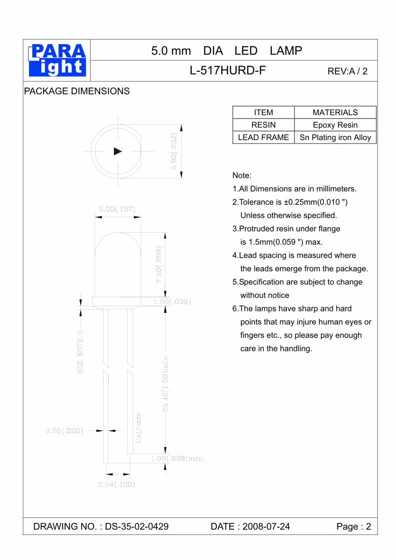
L-517HURD-F REV:A / 2 PACKAGE DIMENSIONS
ITEM MATERIALS RESIN Epoxy Resin
LEAD FRAME Sn Plating iron Alloy
DRAWING NO. : DS-35-02-0429 DATE : 2008-07-24 Page : 2
Note:
1.All Dimensions are in millimeters.
2.Tolerance is ±0.25mm(0.010 ")
Unless otherwise specified.
3.Protruded resin under flange
is 1.5mm(0.059 ") max.
4.Lead spacing is measured where
the leads emerge from the package.
5.Specification are subject to change
without notice
6.The lamps have sharp and hard
points that may injure human eyes or
fingers etc., so please pay enough
care in the handling.
5.0 mm DIA LED LAMP
L-517HURD-F REV:A / 2 FEATURES * 5.0 mm DIA LED LAMP. * HIGH LUMINOUS INTENSITY OUTPUT. * LOW POWER CONSUMPTION. * HIGH EFFICIENCY. * VERSATILE MOUNTING ON P.C. BOARD OR PANEL. * I.C. COMPATIBLE. * Pb FREE PRODUCTS
CHIP MATERIALS * Dice Material : GaAlInP/GaAs * Light Color : ULTRA RED * Lens Color : RED DIFFUSED
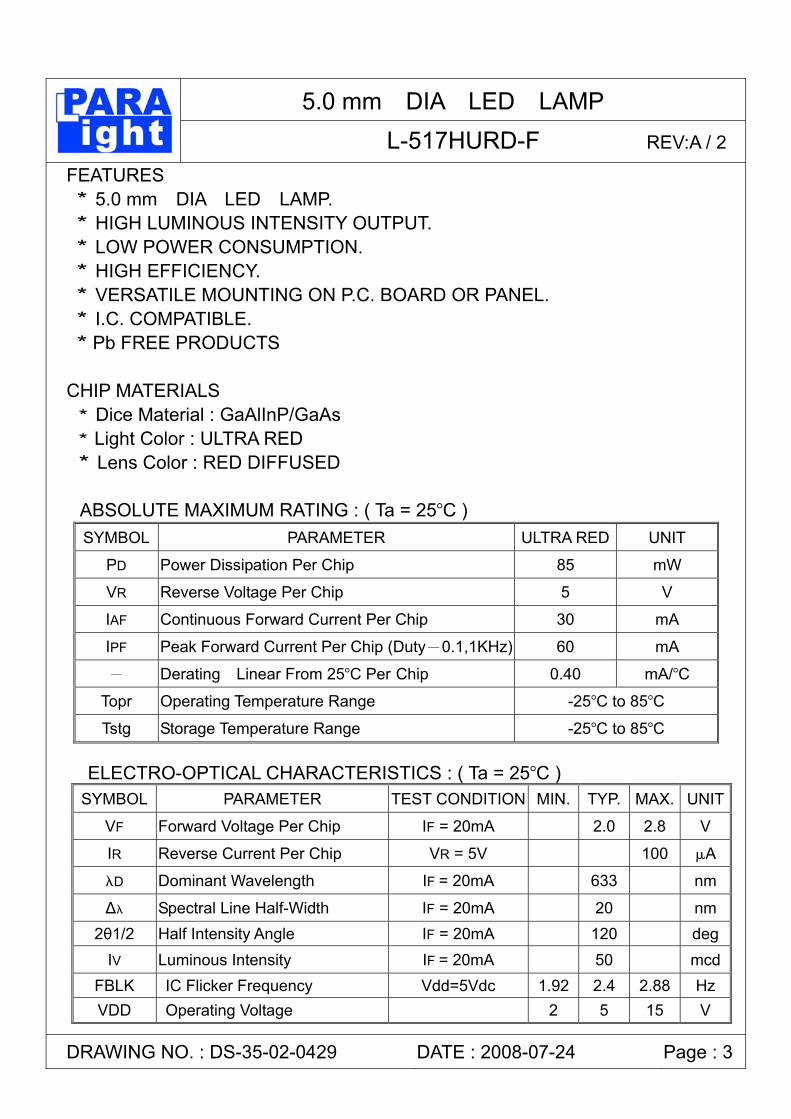
ABSOLUTE MAXIMUM RATING : ( Ta = 25°C )
SYMBOL PARAMETER ULTRA RED UNIT
PD Power Dissipation Per Chip 85 mW
VR Reverse Voltage Per Chip 5 V
IAF Continuous Forward Current Per Chip 30 mA
IPF Peak Forward Current Per Chip (Duty-0.1,1KHz) 60 mA
- Derating Linear From 25°C Per Chip 0.40 mA/°C
Topr Operating Temperature Range -25°C to 85°C
Tstg Storage Temperature Range -25°C to 85°C ELECTRO-OPTICAL CHARACTERISTICS : ( Ta = 25°C )
SYMBOL PARAMETER TEST CONDITION MIN. TYP. MAX. UNIT
VF Forward Voltage Per Chip IF = 20mA 2.0 2.8 V
IR Reverse Current Per Chip VR = 5V 100 µA
λD Dominant Wavelength IF = 20mA 633 nm
∆λ Spectral Line Half-Width IF = 20mA 20 nm 2θ1/2 Half Intensity Angle IF = 20mA 120 deg
IV Luminous Intensity IF = 20mA 50 mcdFBLK IC Flicker Frequency Vdd=5Vdc 1.92 2.4 2.88 Hz VDD Operating Voltage 2 5 15 V
DRAWING NO. : DS-35-02-0429 DATE : 2008-07-24 Page : 3
5.0 mm DIA LED LAMP
L-517HURD-F REV:A / 2
DRAWING NO. : DS-35-02-0429 DATE : 2008-07-24 Page : 4

5.0 mm DIA LED LAMP
L-517HURD-F REV:A / 2
Label Explanation
PARA NO. : Refer to p13 LOT NO. : E L L 4 7 0009
A---E: For series number B---L: Local F: Foreign C---L: LAMP D---Year E---Month F---SPEC.
DRAWING NO. : DS-35-02-0429 DATE : 2008-07-24 Page : 5
A B C D E F
光鼎电子股份有限公司

5.0 mm DIA LED LAMP
L-517HURD-F REV:A / 2 SOLDERING
METHOD SOLDERING CONDITIONS REMARK
DIP SOLDERING
Bath temperature: 260℃ Immersion time: with 5 sec, 1 time
Solder no closer than 3mm from the
base of the package Using soldering flux,” RESIN FLUX” is recommended.
Attached data of temperatuare cure for your reference
SOLDERING IRON
Soldering iron: 30W or smaller Temperature at tip of iron: 300 or lower℃
Soldering time: within 5 sec.
During soldering, take care not to press the tip of iron against the lead.
(To prevent heat from being transferred directly to the lead, hold the lead with a pair of tweezers while soldering
1) When soldering the lead of LED in a condition that the package is fixed with a panel (See Fig.1), be careful not to stress the leads with iron tip.
� 2) When soldering wire to the lead, work with a Fig (See Fig.2) to avoid stressing the package. � Regarding solution in the tinning oven for product-tinning, compound sub-solution made of tin & copper and sliver is proposed with the temperature of Celsius 260. The proportion of the alloyed solution is tin 95.5: copper 3.5: silver 0.5 by percentage. The time of tinning is constantly 3 seconds.
DRAWING NO. : DS-35-02-0429 DATE : 2008-07-24 Page : 6
Panel (Fig.1)
Lead wries
Leave a slight clearance
Lead wries
(Fig .2)
5.0 mm DIA LED LAMP
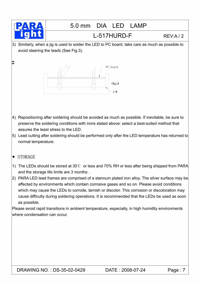
L-517HURD-F REV:A / 2 3) Similarly, when a jig is used to solder the LED to PC board, take care as much as possible to
avoid steering the leads (See Fig.3). � 4) Repositioning after soldering should be avoided as much as possible. If inevitable, be sure to
preserve the soldering conditions with irons stated above: select a best-suited method that assures the least stress to the LED.
5) Lead cutting after soldering should be performed only after the LED temperature has returned to normal temperature.
STORAGE
1) The LEDs should be stored at 30℃ or less and 70% RH or less after being shipped from PARAand the storage life limits are 3 months .
2) PARA LED lead frames are comprised of a stannum plated iron alloy. The silver surface may be affected by environments which contain corrosive gases and so on. Please avoid conditions which may cause the LEDs to corrode, tarnish or discolor. This corrosion or discoloration may cause difficulty during soldering operations. It is recommended that the LEDs be used as soon as possible.
Please avoid rapid transitions in ambient temperature, especially, in high humidity environments where condensation can occur.
DRAWING NO. : DS-35-02-0429 DATE : 2008-07-24 Page : 7
PC board
ig.3)(F
jig

5.0 mm DIA LED LAMP
L-517HURD-F REV:A / 2 LED MOUNTING METHOD
3) When mounting the LED by using a case, as shown Fig.4, ensure that the mounting holds on the PC board match the pitch of the leads correctly-tolerance of dimensions of the respective components including the LED should be taken into account especially when designing the case, PC board, etc. to prevent pitch misalignment between the leads and board holes, the diameter of the board holes should be slightly larger than the size of the lead. Alternatively, the shape of the holes should be made oval. (See Fig.4)
4) Use LEDs with stand-off (Fig.5) or the tube or spacer made of resin (Fig.6) to position the LEDs.
DRAWING NO. : DS-35-02-0429 DATE : 2008-07-24 Page : 8
Fig.4
case
pc board
Stand-off
Fig.5 Fig.6
Tube

5.0 mm DIA LED LAMP
L-517HURD-F REV:A / 2 FORMED LEAD
1) The lead should be bent at a point located at least 2mm away from the package. Bending should be performed with base fixed means of a jig or pliers (Fig.7)
2) Forming lead should be carried our prior to soldering and never during or after soldering. 3) Form the lead to ensure alignment between the leads and the hole on board, so that stress
against the LED is prevented. (Fig.8) LEAD STRENGTH
1) Bend strength Do not bend the lead more than twice. (Fig.9)
DRAWING NO. : DS-35-02-0429 DATE : 2008-07-24 Page :9
2mm
Fig.7
Fig.9

5.0 mm DIA LED LAMP
L-517HURD-F REV:A / 2 2) Tensile strength (@Room Temperature)
If the force is 1kg or less, there will be no problem. (Fig.10) HEAT GENERATION
1) Thermal design of the end product is of paramount importance. Please consider the heat generation of the LED when making the system design. The coefficient of temperature increase per input electric power is affected by the thermal resistance of the circuit board and density of LED placement on the board, as well as other components. It is necessary to avoid intense heat generation and operate within the maximum ratings given in this specification.
The operating current should be decided after considering the ambient maximum temperature of LEDs. CHEMICAL RESISTANCE
1) Avoid exposure to chemicals as it may attack the LED surface and cause discoloration. 2) When washing is required, refer to the following table for the proper chemical to be sued.
(Immersion time: within 3 minutes at room temperature.) SOLVENT ADAPTABILITY Freon TE ⊙
Chlorothene ╳ Isopropyl Alcohol ⊙
Thinner ╳ Acetone ╳
Trichloroethylene ╳ ⊙--Usable ╳--Do not use.
DRAWING NO. : DS-35-02-0429 DATE : 2008-07-24 Page :10
OK!
Fig.10
1Kg
NOTE: Influences of ultrasonic cleaning of the LED
resin body differ depending on such factors
as the oscillator output, size of the PC board
and the way in which the LED is mounted. Therefore, ultrasonic cleaning should only be performed after confirming there is no problem by conducting a test under practical.

5.0 mm DIA LED LAMP
L-517HURD-F REV:A / 2 OTHERS
1) Care must be taken to ensure that the reverse voltage will not exceed the absolute maximum rating when using the LEDs with matrix drive.
2) Flashing lights have been known to cause discomfort in people; you can prevent this by taking precautions during use. Also, people should be cautious when using equipment that has had LEDs incorporated into it.
3) The LEDs described in this brochure are intended to be used for ordinary electronic equipment (such as office equipment, communications equipment, measurement instruments and household appliances). Consult PARA’s sales staff in advance for information on the applications in which exceptional quality and reliability are required , particularly when the failure or malfunction of the LEDs may directly jeopardize life or health (such as for airplanes, aerospace, submersible repeaters, nuclear reactor control systems, automobiles, traffic control equipment, life support systems and safety devices).
4) User shall not reverse engineer by disassembling or analysis of the LEDs without having prior written consent from PARA. When defective LEDs are found, the User shall inform PARA directly before disassembling or analysis.
5) The formal specifications must be exchanged and signed by both parties before large volume purchase begins.
6) The appearance and specifications of the product may be modified for improvement without notice.
DRAWING NO. : DS-35-02-0429 DATE : 2008-07-24 Page :11

5.0 mm DIA LED LAMP
L-517HURD-F REV:A / 2 LED Lamps:
DRAWING NO. : DS-35-02-0429 DATE : 2008-07-24 Page :12