database design (physical) modeling standards and guidelines · database design (physical) modeling...
TRANSCRIPT
DATABASE DESIGN
(PHYSICAL) MODELING
STANDARDS AND
GUIDELINES
Version 2.0.1
August 22, 2017
Information Systems Branch
Economy Sector
Database Design (Physical) Modeling Standards and Guidelines
TABLE OF CONTENTS Revision History .................................................................................................................. 5
1 Introduction ................................................................................................................. 6
1.1 Target Audience .................................................................................................. 6
1.2 Purpose ............................................................................................................... 6
1.3 Assumptions ........................................................................................................ 6
2 Security Access Policy .................................................................................................. 6
3 Definitions .................................................................................................................... 7
3.1 Guideline ............................................................................................................. 7
3.2 Standard .............................................................................................................. 7
3.3 Application Naming ............................................................................................. 7
4 Design Phase ................................................................................................................ 8
4.1 General Guidelines .............................................................................................. 8
Referencing Objects in Text Descriptions ....................................................... 8 4.1.1
Keeping physical and logical data models current ......................................... 8 4.1.2
Electronic Delivery of the Application ............................................................ 9 4.1.3
4.2 Database Design ................................................................................................. 9
Objectives...................................................................................................... 10 4.2.1
Deliverables ................................................................................................... 10 4.2.2
Object Naming Conventions ......................................................................... 12 4.2.3
Database Design Transformer ...................................................................... 13 4.2.4
Standard Table Enhancements ..................................................................... 16 4.2.5
Journal Tables ............................................................................................... 17 4.2.6
Databases ...................................................................................................... 19 4.2.7
Tablespaces ................................................................................................... 21 4.2.8
Datafiles ........................................................................................................ 22 4.2.9
Tables ........................................................................................................ 23 4.2.10
Columns .................................................................................................... 24 4.2.11
Views ......................................................................................................... 28 4.2.12
Sequences ................................................................................................. 30 4.2.13
Constraints ................................................................................................ 31 4.2.14
Database Design (Physical) Modeling Standards and Guidelines
Indexes ...................................................................................................... 35 4.2.15
PL/SQL Definitions .................................................................................... 36 4.2.16
Storage Definitions ................................................................................... 42 4.2.17
Synonyms .................................................................................................. 43 4.2.18
Database Object Grants ............................................................................ 43 4.2.19
SQL Statement Tuning .............................................................................. 44 4.2.20
5 Build Phase ................................................................................................................ 45
5.1 Overall Guidelines ............................................................................................. 45
Referencing Objects in Text Descriptions ..................................................... 45 5.1.1
Keeping logical and physical data models current ....................................... 46 5.1.2
Documenting Post-Generation Changes ...................................................... 46 5.1.3
5.2 Implementation of Database Objects ............................................................... 47
Users ............................................................................................................. 48 5.2.1
System and Application Roles ....................................................................... 49 5.2.2
Table Implementations ................................................................................. 52 5.2.3
Sequence Implementations .......................................................................... 52 5.2.4
User Object Index Storages ........................................................................... 53 5.2.5
PL/SQL Modules ............................................................................................ 53 5.2.6
5.3 Updating Bound Columns in Modules .............................................................. 54
5.4 Preferences ....................................................................................................... 54
Objectives...................................................................................................... 54 5.4.1
5.5 Code Tables ....................................................................................................... 55
5.6 Designer Generated Reference Codes - REF_CODES ........................................ 55
6 Maintenance Phase ................................................................................................... 57
6.1 Overall Guidelines ............................................................................................. 57
Synchronizing Table Definitions .................................................................... 57 6.1.1
Synchronizing View Definitions .................................................................... 57 6.1.2
Synchronizing Domain Definitions ................................................................ 57 6.1.3
Synchronizing Display Information / Comments / Help Text ....................... 59 6.1.4
Synchronizing Entities with Tables ............................................................... 60 6.1.5
Synchronizing Module Definitions ................................................................ 61 6.1.6
7 Designer Generation .................................................................................................. 61
7.1 Generate Database from Server Model ............................................................ 61
Database Design (Physical) Modeling Standards and Guidelines
Post-Generation Changes ............................................................................. 66 7.1.1
Reconcile Report ........................................................................................... 66 7.1.2
Capture Design of Server Model ................................................................... 67 7.1.3
Capture Design of Supporting Tables ........................................................... 68 7.1.4
7.2 Appendix B – Glossary of Terms ...................................................................... 70
7.3 Appendix C – Standard Approved Abbreviations ............................................. 71
Mandatory Abbreviations ............................................................................. 71 7.3.1
Preferred Abbreviations ............................................................................... 71 7.3.2
Database Design (Physical) Modeling Standards and Guidelines
REVISION HISTORY
Date Version Author Description
2017-08-10 2.0.0 Maureen Bird
Pulled database design modeling information from CS_TSA_Designer10g_Standards_and_Guidelines document and incorporated into new standard template.
2017-08-21 2.0.1 Kerri Warnes
Updating Deliverables section to include toolsets and timelines.
Database Design (Physical) Modeling Standards and Guidelines
1 INTRODUCTION This document describes the guidelines and standards to be followed when designing and developing applications for the Economy Sector of the Province of British Columbia. At time of writing, the Economy Sector consists of the Ministry of Jobs, Trade & Technology, Ministry of Labour, Ministry of Municipal Affairs & Housing, and Ministry of Tourism, Arts & Culture. Originally the Oracle Designer standards for the Ministry of Sustainable Resource Management, this document has been taken, with permission from that Ministry, and modified to suit our Sector’s unique requirements. While the standards originally spoke to modeling within Oracle Designer, this adapted version is intended to be tool agnostic. Where a deliverable (or method of delivery) is Oracle Designer-specific, it will be specified. As with any standards document, this document will evolve over time. It is fully expected that each and every development effort will contribute to the evolution of this document.
1.1 TARGET AUDIENCE This document is directed at those who will be designing, developing, and maintaining application systems for the Economy Sector. This includes external contractors, consultants, and business partners, as well as ministry employees (Data Administrator, Database Administrator, Business Analyst and Application Analysts).
1.2 PURPOSE This document outlines the physical database standards which must be followed when building application systems for the Economy Sector.
1.3 ASSUMPTIONS As it is not the intent of this document to be an 'all inclusive' guide, it is assumed that the audience has a working knowledge of relational databases. Throughout the remainder of the document, the ministries represented by the Economy Sector shall be referred to as “The Ministry”.
2 SECURITY ACCESS POLICY
Database Design (Physical) Modeling Standards and Guidelines
Audience: ISB Staff, External Contractors, Clients The Data and Database Administration Group within the Ministry Information Systems Branch (ISB) is ultimately responsible for the management, data integrity, and security of the ministry's data repositories. Due to the inherent complexities and risks associated with managing metadata within any SCM environment and repositories, the ISB will restrict "Create/Update/Delete" access only to specific external development resources and select ISB staff. "Read only" access may be provided to other individuals in the ministry if deemed necessary on a case-by-case basis. This policy will be firmly enforced by the ISB.
3 DEFINITIONS
3.1 GUIDELINE A guideline is a method or custom, which through common usage has become an accepted method of work. A guideline is not enforced, and is not a standard.
3.2 STANDARD A standard is a specific statement of the rules and constraints governing the naming, contents, and operations of software. Some statements are in bold, to emphasize standards that have been overlooked in the past. Unless otherwise noted, every statement in this document is a standard.
3.3 APPLICATION NAMING Applications must be named ideally with as a 3-4 character short name or acronym that is unique within the business area or corporation. The expanded name should be recorded in the Title property. When developing an Oracle database this Application Name will be automatically prefixed to all 'physical' database objects such as tables, views, packages, sequences and roles (see Database Design Transformer). Functions and procedures that are not encapsulated in packages should also be prefixed with this name. The intent of requiring the prefixing of the Application Name on all objects is to reduce the possibility of namespace collisions in a shared Database environment. For example, the LGIS application uses LGIS as its short name. Therefore, the SCHEDULE entity becomes the LGIS_SCHEDULES table.
Database Design (Physical) Modeling Standards and Guidelines
Approval to use a new application acronym must be obtained from the Corporate Data Administrator or Corporate Database Administrator to ensure that there are no duplicate names.
4 DESIGN PHASE
4.1 GENERAL GUIDELINES This section presents some overall guidelines to assist in the Design Phase within the Oracle Designer environment. Although the below Guidelines reference Oracle Designer they are applicable to other Development Toolsets. The outcome is to achieve an accurate, descriptive and updatable Data Model. The use of a toolset (such as Oracle SSDM, Erwin Data Modeller, Enterprise Architect) to automate the requested Diagrams and Reports outlined below is ideal. All Development toolsets must be reviewed and approved by the Ministry before work commences.
Referencing Objects in Text Descriptions 4.1.1 Whenever the name of another TABLE, COLUMN (or any other object) is used within a textual description, it should be capitalized for easier reading (and reference). For example, if ADAMS_MODEMS is a table, then the following description should be used for the ADAMS_MODEM_TYPES table:
"This table identifies the types of ADAMS_MODEMS that are available to the polling system"
Note: This may make maintenance of this text difficult, as changes in table names would necessitate updates to the descriptive text. Therefore, this is a recommended guideline, and not a Ministry standard.
Keeping physical and logical data models current 4.1.2 In the Design Phase, there may be corrections and/or additions to the data requirements (i.e. new column). Aside from de-normalization or other issues specific to physical implementation, all such changes must be re-documented in the logical data
Database Design (Physical) Modeling Standards and Guidelines
model, either via the Table to Entity Retrofit Utility or via manual update of entities, attributes and relationships. See Synchronizing Entities with Tables for further information on the Table to Entity Retrofit Utility.
Electronic Delivery of the Application 4.1.3 All development is ideally done directly within the Ministry Repository, so no explicit delivery is required. If an alternative toolset is chosen it must be approved by the Ministry for use and delivery of any models or reports will be checked into the Ministries SCM Repository as outline within the Application’s Project Management timelines for review by the Ministry’s ISB staff.
4.2 DATABASE DESIGN The Database Design (Physical Data Modeling) process involves the conversion of entities, attributes, relationships, and other logical constructs to their physical database counterparts. Specifically, entities are mapped to their corresponding table definitions, attributes to their corresponding column definitions, relationships to their corresponding foreign key definitions, and so on. The process of converting analysis data into tables and foreign key constraints ideally should be automated by a Ministry approved toolset chosen before a Project begins. Regardless of the toolset used the Objects and Deliverables stated below remain. Within a toolset such as Oracle Designer the process is automated by the Database Design Transformer (DDT). The Database Design Transformer creates and maintains database designs based upon entity, attribute and relationship information previously recorded in the Designer Repository. The Database Design Transformer creates tables to record instances of each entity, columns to store the attributes, and constraints to implement the relationships between entities. It also creates constraints to enforce any unique identifiers that have been defined, and indexes to support foreign keys. The Database Design Transformer generated database design is stored in the Designer Repository. This model can subsequently be used by the Server Generator to generate the SQL DDL statements required to create the associated database objects. The Server Model Diagrammer is a graphical tool for modeling logical database schema designs. The database objects within the schema can be represented graphically on one or more data diagrams. These diagrams depict the relationships between tables, views and snapshots recorded in the Designer repository. After a first cut database design is
Database Design (Physical) Modeling Standards and Guidelines
completed using the Database Design Transformer, the Server Model Diagrammer can be utilized to refine the database design. De-normalization and the addition of columns to support special processing logic may be done as required. This must, however, be fully documented in the description for the column and must be done with DBA approval.
Objectives 4.2.1 The objectives of the Database Design process are:
To ensure that all entities, attributes, and relationships that are to be physically implemented have corresponding database objects.
To ensure that the transition from the logical model to the physical database design is documented.
To provide an accurate model of the database requirements of the organization. This model can subsequently be used by the Server Generator to generate the statements required to create the associated database objects.
Deliverables 4.2.2 The Database Design document to be presented for sign-off will contain the following diagrams and reports:
Proposed Database Design
Entity to Table Implementation
Table Definition Report
Server Model Diagram
Database Table and Index Size Estimates
Role Definition Report A checklist is available to confirm that the Database Design task is complete and that the repository is ready for the Build Phase. This checklist is used in conjunction with the deliverables stated above.
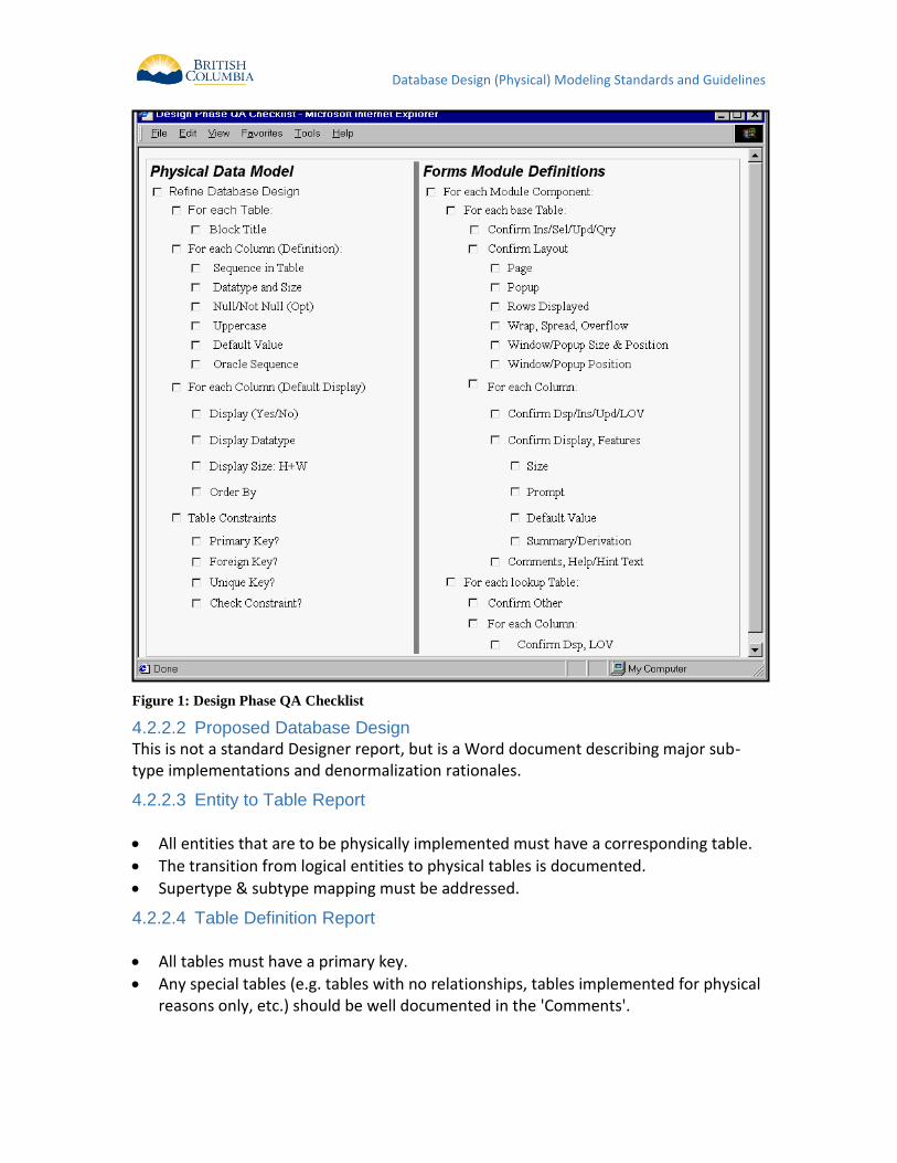
Design Phase QA Checklist 4.2.2.1
Database Design (Physical) Modeling Standards and Guidelines
Figure 1: Design Phase QA Checklist
Proposed Database Design 4.2.2.2
This is not a standard Designer report, but is a Word document describing major sub-type implementations and denormalization rationales.
Entity to Table Report 4.2.2.3
All entities that are to be physically implemented must have a corresponding table.
The transition from logical entities to physical tables is documented.
Supertype & subtype mapping must be addressed.
Table Definition Report 4.2.2.4
All tables must have a primary key.
Any special tables (e.g. tables with no relationships, tables implemented for physical reasons only, etc.) should be well documented in the 'Comments'.
Database Design (Physical) Modeling Standards and Guidelines
All columns should be understandable (either by its name or by the comments or by the use of an example in the comments about that column) to a non-application person.
Server Model Diagram 4.2.2.5
One or more diagrams should be made to show the relationships between the tables
Database Table and Index Size Estimates 4.2.2.6
As this report tables the volume estimates for all tables and columns (inherited from their corresponding entities and attributes during the table generation process with the Database Design Transformer) and calculates approximate sizes for the tablespaces. This report is vitally important; it is the Ministry standard that these sizing estimates be performed.
Role Definition Report 4.2.2.7
This report shows the database roles in the application. All security should be enforced at the server, using role-based security.
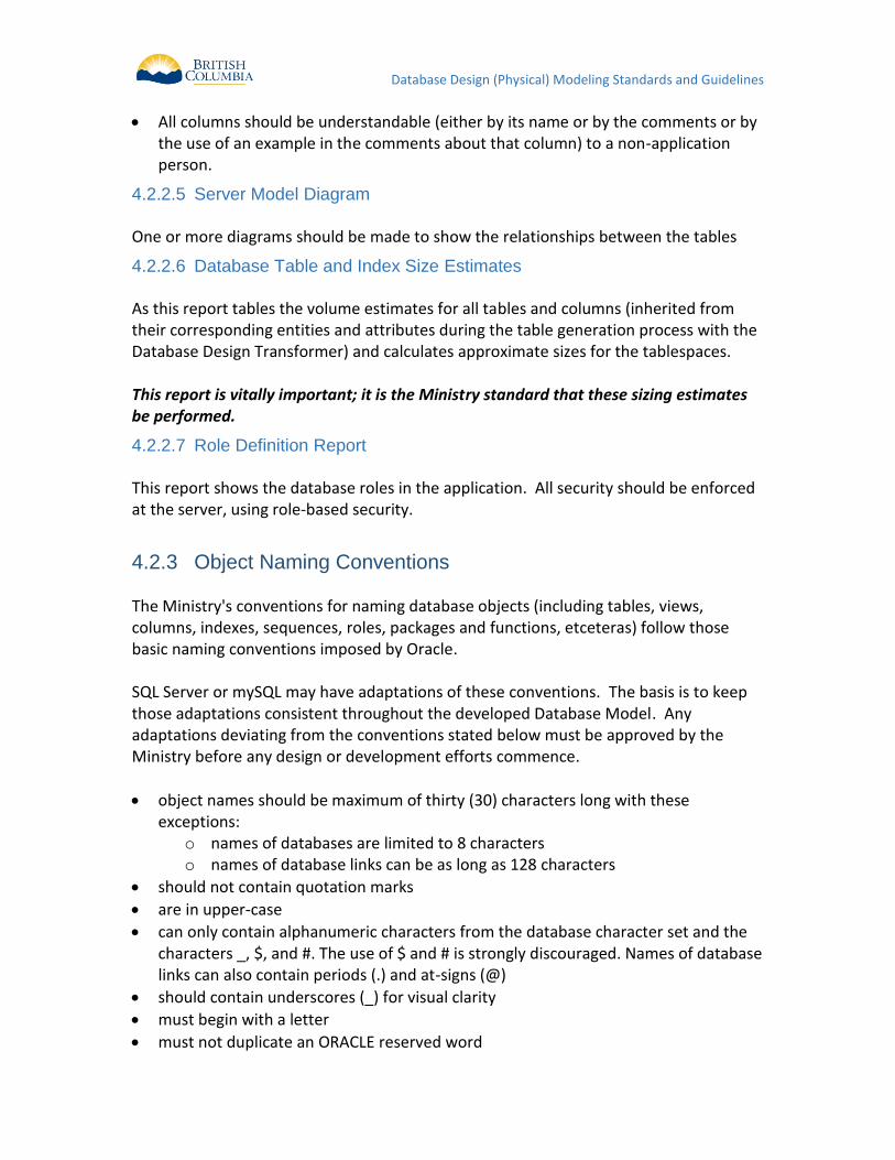
Object Naming Conventions 4.2.3 The Ministry's conventions for naming database objects (including tables, views, columns, indexes, sequences, roles, packages and functions, etceteras) follow those basic naming conventions imposed by Oracle. SQL Server or mySQL may have adaptations of these conventions. The basis is to keep those adaptations consistent throughout the developed Database Model. Any adaptations deviating from the conventions stated below must be approved by the Ministry before any design or development efforts commence.
object names should be maximum of thirty (30) characters long with these exceptions:
o names of databases are limited to 8 characters o names of database links can be as long as 128 characters
should not contain quotation marks
are in upper-case
can only contain alphanumeric characters from the database character set and the characters _, $, and #. The use of $ and # is strongly discouraged. Names of database links can also contain periods (.) and at-signs (@)
should contain underscores (_) for visual clarity
must begin with a letter
must not duplicate an ORACLE reserved word
Database Design (Physical) Modeling Standards and Guidelines
should not contain the word DUAL (e.g. DUAL is the name of a dummy table frequently accessed by Oracle tools such as SQL*Plus and Forms)
must not duplicate the name of another database object
should use nouns, rather than verbs
should be as descriptive and as short as possible
should use standard abbreviations when required (see Appendix C – Standard Approved Abbreviations)
should not be ambiguous
In addition, it is a Ministry standard that the Application Name (acronym such as LGIS) be prefixed to all 'physical' database objects such as tables, views, packages, sequences and roles.
Note: Procedures and functions defined within a package do not need this prefix, as the package itself will be prefixed with the application name.
Database Design Transformer 4.2.4 If developing within Oracle Designer the Database Design Transformer can be used to easily convert the logical model into a physical implementation. Bear in mind, however, that no automated process is without problems; it is the developers' responsibility to ensure that the way that all objects are built is correct and will satisfy the business needs. The following Run Options should be used:
the first time running the DDT, the Create flags are set; subsequent runs will have the Modify flags set to allow modifications to existing objects
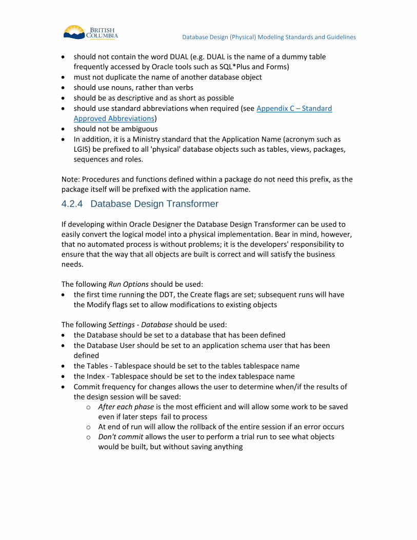
The following Settings - Database should be used:
the Database should be set to a database that has been defined
the Database User should be set to an application schema user that has been defined
the Tables - Tablespace should be set to the tables tablespace name
the Index - Tablespace should be set to the index tablespace name
Commit frequency for changes allows the user to determine when/if the results of the design session will be saved:
o After each phase is the most efficient and will allow some work to be saved even if later steps fail to process
o At end of run will allow the rollback of the entire session if an error occurs o Don't commit allows the user to perform a trial run to see what objects
would be built, but without saving anything
Database Design (Physical) Modeling Standards and Guidelines
Figure 2: DDT Settings - Database
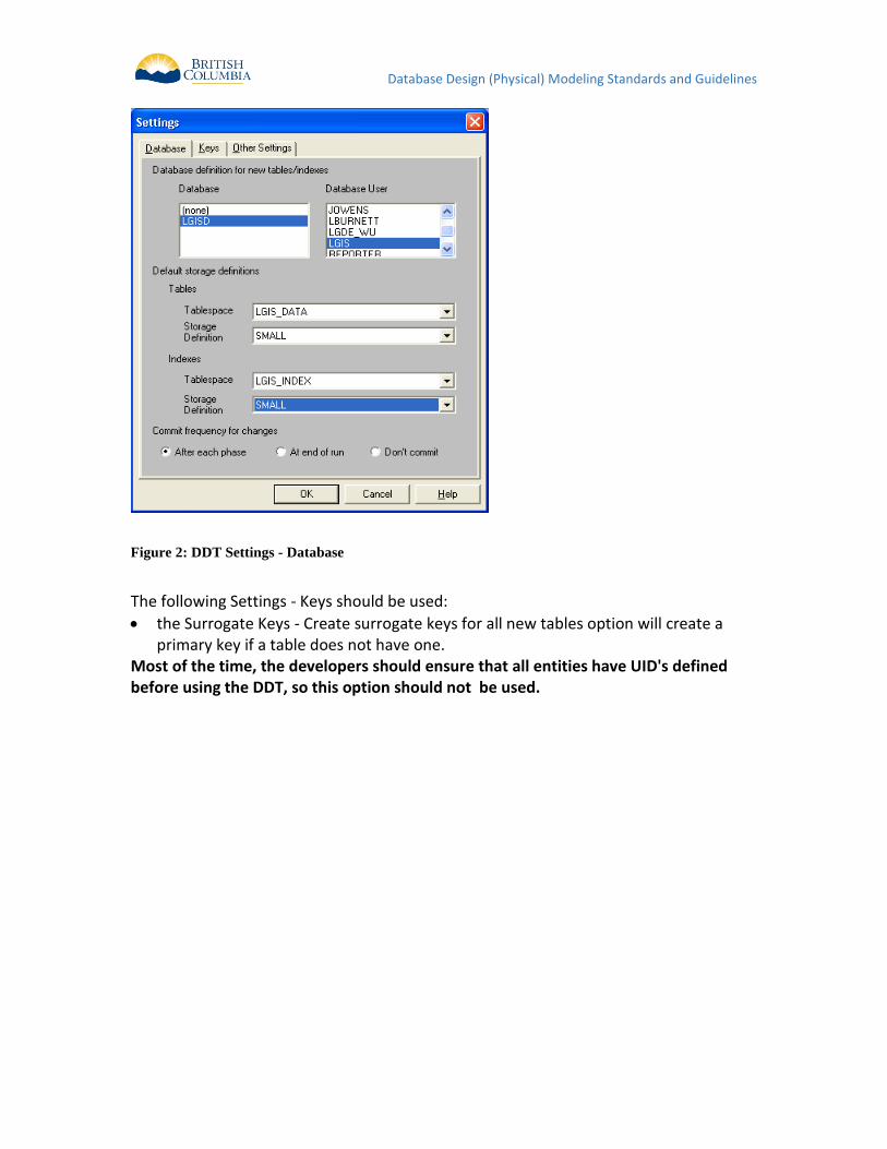
The following Settings - Keys should be used:
the Surrogate Keys - Create surrogate keys for all new tables option will create a primary key if a table does not have one.
Most of the time, the developers should ensure that all entities have UID's defined before using the DDT, so this option should not be used.
Database Design (Physical) Modeling Standards and Guidelines
Figure 3: DDT Settings - Keys
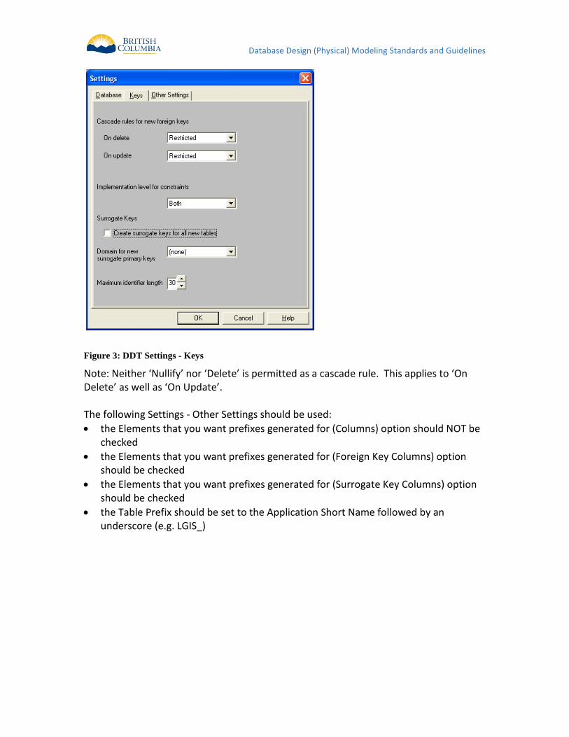
Note: Neither ‘Nullify’ nor ‘Delete’ is permitted as a cascade rule. This applies to ‘On Delete’ as well as ‘On Update’. The following Settings - Other Settings should be used:
the Elements that you want prefixes generated for (Columns) option should NOT be checked
the Elements that you want prefixes generated for (Foreign Key Columns) option should be checked
the Elements that you want prefixes generated for (Surrogate Key Columns) option should be checked
the Table Prefix should be set to the Application Short Name followed by an underscore (e.g. LGIS_)
Database Design (Physical) Modeling Standards and Guidelines
Figure 4: DDT Settings - Other
Standard Table Enhancements 4.2.5 Tables which record transactions, or go through changes in state due to a business process, must have these audit columns. For all other tables, it is still mandatory to include these columns; this is especially important for data warehouse replication to determine when data values have changed. They allow a degree of simple security tracking, but can also be useful in tracing down problems. As per the Error! Reference source not found. section, these columns will be utomatically generated from the source attributes. It is the Ministry standard that the following audit columns be included in all tables:
CREATE_USERID not null varchar2(30)
CREATE_TIMESTAMP not null date
UPDATE_USERID not null varchar2(30)
UPDATE_TIMESTAMP not null date
Database triggers should be created on the tables to fill these columns. The following code can be used as an example for the trigger functionality necessary: CREATE OR REPLACE TRIGGER LGIS_IV_BR_IUD_TRG
BEFORE INSERT OR UPDATE
ON LGIS_INSTANCE_VALUES
Database Design (Physical) Modeling Standards and Guidelines
FOR EACH ROW
DECLARE
BEGIN
if inserting then
:new.create_userid:= user;
:new.create_timestamp:= sysdate;
:new.update_userid := user;
:new.update_timestamp := sysdate;
if :new.identifier is null then
select prt_staffs_seq.nextval into :new.identifier from dual;
end if;
elsif updating then
:new.update_userid := user;
:new.update_timestamp := sysdate;
end if;
END;
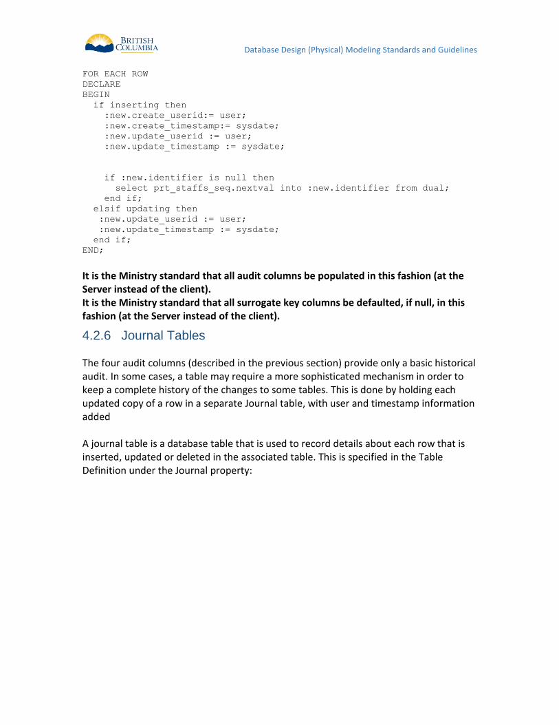
It is the Ministry standard that all audit columns be populated in this fashion (at the Server instead of the client). It is the Ministry standard that all surrogate key columns be defaulted, if null, in this fashion (at the Server instead of the client).
Journal Tables 4.2.6 The four audit columns (described in the previous section) provide only a basic historical audit. In some cases, a table may require a more sophisticated mechanism in order to keep a complete history of the changes to some tables. This is done by holding each updated copy of a row in a separate Journal table, with user and timestamp information added A journal table is a database table that is used to record details about each row that is inserted, updated or deleted in the associated table. This is specified in the Table Definition under the Journal property:
Database Design (Physical) Modeling Standards and Guidelines
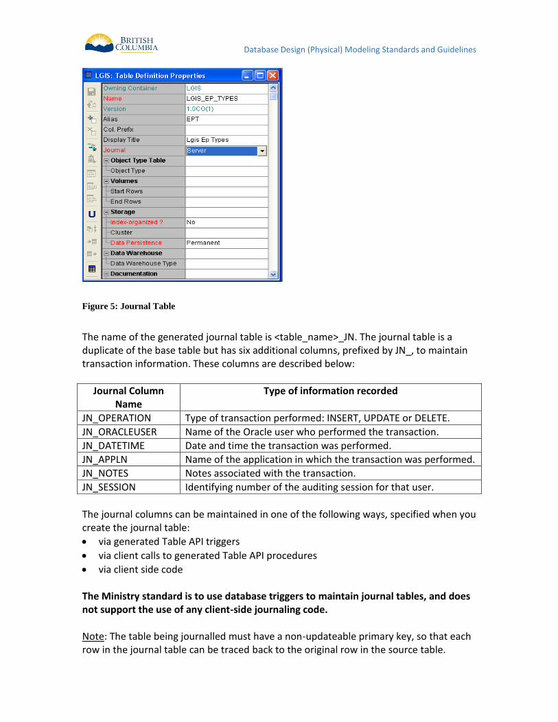
Figure 5: Journal Table
The name of the generated journal table is <table_name>_JN. The journal table is a duplicate of the base table but has six additional columns, prefixed by JN_, to maintain transaction information. These columns are described below:
Journal Column Name
Type of information recorded
JN_OPERATION Type of transaction performed: INSERT, UPDATE or DELETE.
JN_ORACLEUSER Name of the Oracle user who performed the transaction.
JN_DATETIME Date and time the transaction was performed.
JN_APPLN Name of the application in which the transaction was performed.
JN_NOTES Notes associated with the transaction.
JN_SESSION Identifying number of the auditing session for that user.
The journal columns can be maintained in one of the following ways, specified when you create the journal table:
via generated Table API triggers
via client calls to generated Table API procedures
via client side code The Ministry standard is to use database triggers to maintain journal tables, and does not support the use of any client-side journaling code. Note: The table being journalled must have a non-updateable primary key, so that each row in the journal table can be traced back to the original row in the source table.
Database Design (Physical) Modeling Standards and Guidelines
Note: There is no means of recording a storage clause against a journal table. However, by reverse engineering these tables into the repository, you may record this information against the resulting table definitions.
Databases 4.2.7 Any SQL Server Application or Service Level Users and Roles need to be defined. No Application or Service account should be granted the “Fixed Server Role” db_owner unless approved by the Ministry before commencing development. Ideally Application or Service accounts should have a ROLE defined and developed using least-privileged access (LUA). An example of this is Role-Based Permission db_executor to execute a Stored Procedure or Function instead of the grant of db_owner. Any Fixed Server Role other than db_datareader or db_datawriter must be evaluated and approved by the Ministry before it will be deployed for use. An Oracle Database and appropriate application level users and roles will need to be defined before running the Database Design Transformer or any of the module or DDL generators.
Property Rule Req?
Database Name
Should be set to “CSPROD” as a default Target. No SYSTEM level scripts will be generated by the developer using this value, but it is useful metadata for the application to maintain.
Y
Oracle Version
should be set to Oracle 11g for new development Y
Complete ? must be Yes Y
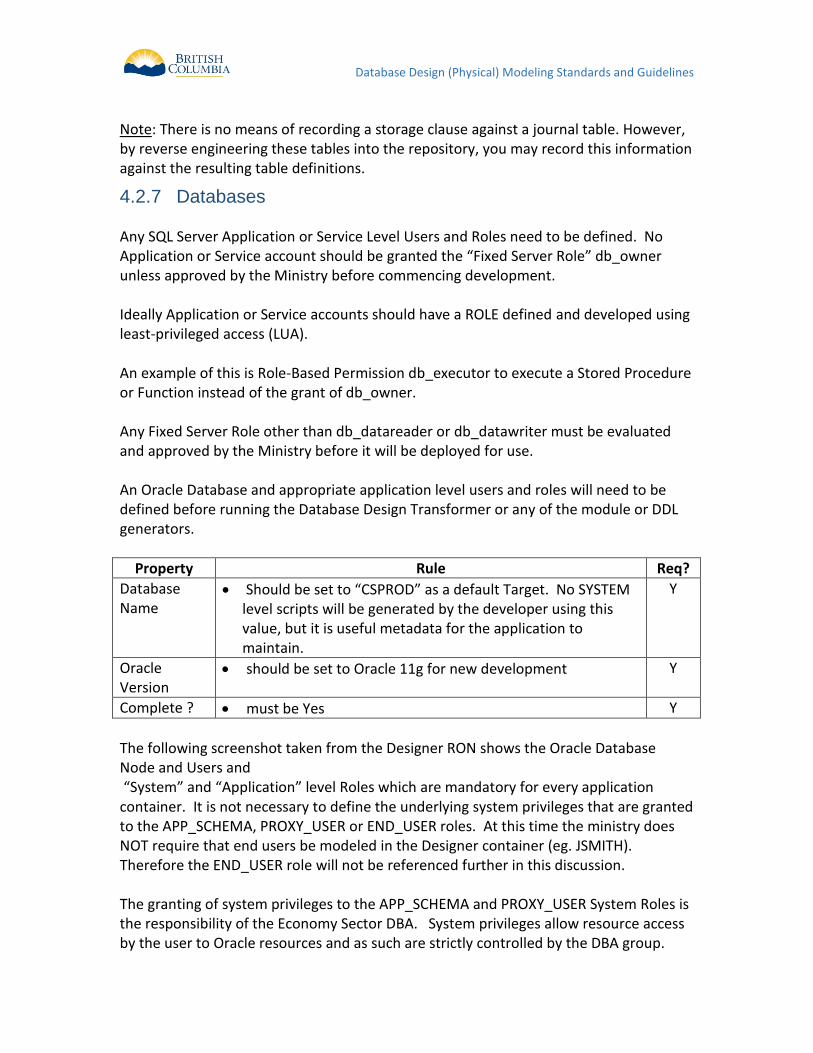
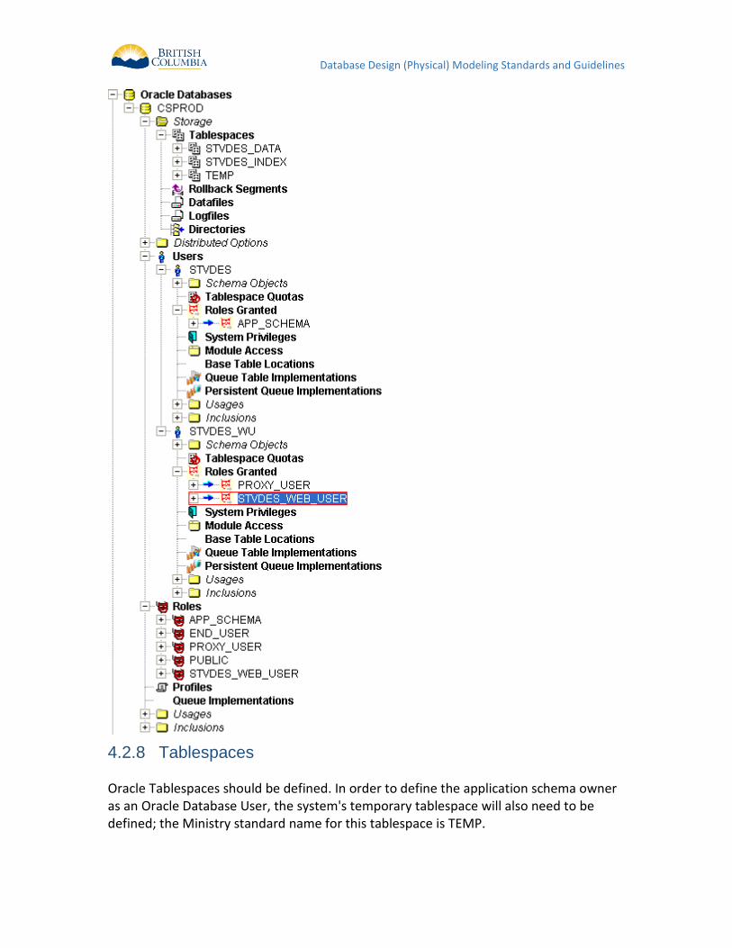
The following screenshot taken from the Designer RON shows the Oracle Database Node and Users and “System” and “Application” level Roles which are mandatory for every application container. It is not necessary to define the underlying system privileges that are granted to the APP_SCHEMA, PROXY_USER or END_USER roles. At this time the ministry does NOT require that end users be modeled in the Designer container (eg. JSMITH). Therefore the END_USER role will not be referenced further in this discussion. The granting of system privileges to the APP_SCHEMA and PROXY_USER System Roles is the responsibility of the Economy Sector DBA. System privileges allow resource access by the user to Oracle resources and as such are strictly controlled by the DBA group.
Database Design (Physical) Modeling Standards and Guidelines
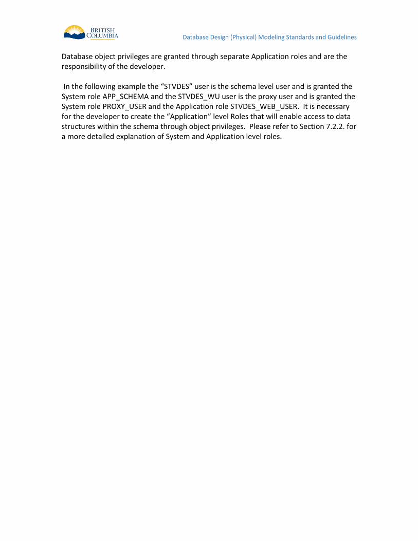
Database object privileges are granted through separate Application roles and are the responsibility of the developer. In the following example the “STVDES” user is the schema level user and is granted the System role APP_SCHEMA and the STVDES_WU user is the proxy user and is granted the System role PROXY_USER and the Application role STVDES_WEB_USER. It is necessary for the developer to create the “Application” level Roles that will enable access to data structures within the schema through object privileges. Please refer to Section 7.2.2. for a more detailed explanation of System and Application level roles.
Database Design (Physical) Modeling Standards and Guidelines
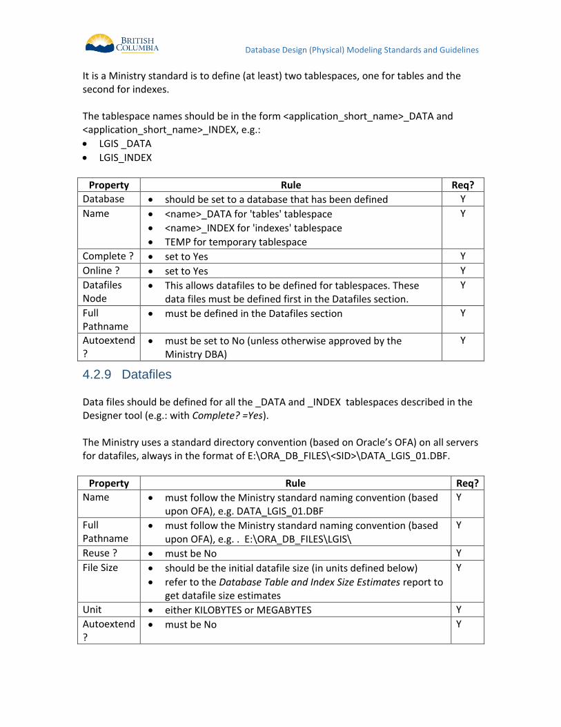
Tablespaces 4.2.8 Oracle Tablespaces should be defined. In order to define the application schema owner as an Oracle Database User, the system's temporary tablespace will also need to be defined; the Ministry standard name for this tablespace is TEMP.
Database Design (Physical) Modeling Standards and Guidelines
It is a Ministry standard is to define (at least) two tablespaces, one for tables and the second for indexes. The tablespace names should be in the form <application_short_name>_DATA and <application_short_name>_INDEX, e.g.:
LGIS _DATA
LGIS_INDEX
Property Rule Req?
Database should be set to a database that has been defined Y
Name <name>_DATA for 'tables' tablespace
<name>_INDEX for 'indexes' tablespace
TEMP for temporary tablespace
Y
Complete ? set to Yes Y
Online ? set to Yes Y
Datafiles Node
This allows datafiles to be defined for tablespaces. These data files must be defined first in the Datafiles section.
Y
Full Pathname
must be defined in the Datafiles section Y
Autoextend ?
must be set to No (unless otherwise approved by the Ministry DBA)
Y
Datafiles 4.2.9 Data files should be defined for all the _DATA and _INDEX tablespaces described in the Designer tool (e.g.: with Complete? =Yes). The Ministry uses a standard directory convention (based on Oracle’s OFA) on all servers for datafiles, always in the format of E:\ORA_DB_FILES\<SID>\DATA_LGIS_01.DBF.
Property Rule Req?
Name must follow the Ministry standard naming convention (based upon OFA), e.g. DATA_LGIS_01.DBF
Y
Full Pathname
must follow the Ministry standard naming convention (based upon OFA), e.g. . E:\ORA_DB_FILES\LGIS\
Y
Reuse ? must be No Y
File Size should be the initial datafile size (in units defined below)
refer to the Database Table and Index Size Estimates report to get datafile size estimates
Y
Unit either KILOBYTES or MEGABYTES Y
Autoextend ?
must be No Y
Database Design (Physical) Modeling Standards and Guidelines
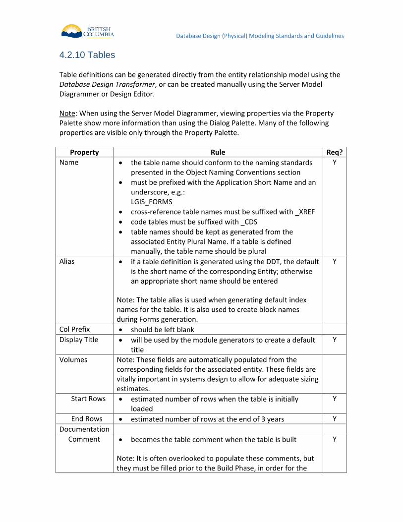
Tables 4.2.10 Table definitions can be generated directly from the entity relationship model using the Database Design Transformer, or can be created manually using the Server Model Diagrammer or Design Editor. Note: When using the Server Model Diagrammer, viewing properties via the Property Palette show more information than using the Dialog Palette. Many of the following properties are visible only through the Property Palette.
Property Rule Req?
Name the table name should conform to the naming standards presented in the Object Naming Conventions section
must be prefixed with the Application Short Name and an underscore, e.g.: LGIS_FORMS
cross-reference table names must be suffixed with _XREF
code tables must be suffixed with _CDS
table names should be kept as generated from the associated Entity Plural Name. If a table is defined manually, the table name should be plural
Y
Alias if a table definition is generated using the DDT, the default is the short name of the corresponding Entity; otherwise an appropriate short name should be entered
Note: The table alias is used when generating default index names for the table. It is also used to create block names during Forms generation.
Y
Col Prefix should be left blank
Display Title will be used by the module generators to create a default title
Y
Volumes Note: These fields are automatically populated from the corresponding fields for the associated entity. These fields are vitally important in systems design to allow for adequate sizing estimates.
Start Rows estimated number of rows when the table is initially loaded
Y
End Rows estimated number of rows at the end of 3 years Y
Documentation
Comment
becomes the table comment when the table is built
Note: It is often overlooked to populate these comments, but they must be filled prior to the Build Phase, in order for the
Y
Database Design (Physical) Modeling Standards and Guidelines
Property Rule Req?
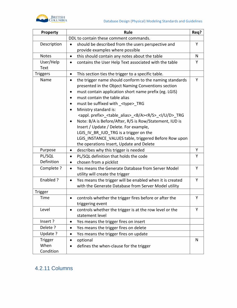
DDL to contain these comment commands.
Description should be described from the users perspective and provide examples where possible
Y
Notes this should contain any notes about the table N
User/Help Text
contains the User Help Text associated with the table Y
Triggers This section ties the trigger to a specific table.
Name the trigger name should conform to the naming standards presented in the Object Naming Conventions section
must contain application short name prefix (eg. LGIS)
must contain the table alias
must be suffixed with _<type>_TRG
Ministry standard is: <appl. prefix>_<table_alias>_<B/A><R/S>_<I/U/D>_TRG
Note: B/A is Before/After, R/S is Row/Statement, IUD is Insert / Update / Delete. For example, LGIS_IV_BR_IUD_TRG is a trigger on the LGIS_INSTANCE_VALUES table, triggered Before Row upon the operations Insert, Update and Delete
Y
Purpose describes why this trigger is needed Y
PL/SQL Definition
PL/SQL definition that holds the code
chosen from a picklist
Y
Complete ? Yes means the Generate Database from Server Model utility will create the trigger
Y
Enabled ? Yes means the trigger will be enabled when it is created with the Generate Database from Server Model utility
Y
Trigger
Time controls whether the trigger fires before or after the triggering event
Y
Level controls whether the trigger is at the row level or the statement level
Y
Insert ? Yes means the trigger fires on insert
Delete ? Yes means the trigger fires on delete
Update ? Yes means the trigger fires on update
Trigger When Condition
optional
defines the when-clause for the trigger
N
Columns 4.2.11
Database Design (Physical) Modeling Standards and Guidelines
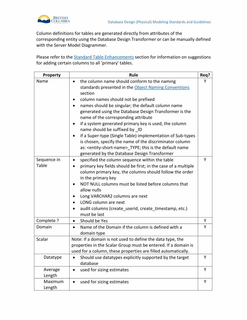
Column definitions for tables are generated directly from attributes of the corresponding entity using the Database Design Transformer or can be manually defined with the Server Model Diagrammer. Please refer to the Standard Table Enhancements section for information on suggestions for adding certain columns to all 'primary' tables.
Property Rule Req?
Name the column name should conform to the naming standards presented in the Object Naming Conventions section
column names should not be prefixed
names should be singular; the default column name generated using the Database Design Transformer is the name of the corresponding attribute
if a system generated primary key is used, the column name should be suffixed by _ID
if a Super-type (Single Table) implementation of Sub-types is chosen, specify the name of the discriminator column as: <entity-short-name>_TYPE; this is the default name generated by the Database Design Transformer
Y
Sequence in Table
specified the column sequence within the table
primary key fields should be first; in the case of a multiple column primary key, the columns should follow the order in the primary key
NOT NULL columns must be listed before columns that allow nulls
Long VARCHAR2 columns are next
LONG column are next
audit columns (create_userid, create_timestamp, etc.) must be last
Y
Complete ? Should be Yes Y
Domain Name of the Domain if the column is defined with a domain type
Y
Scalar Note: If a domain is not used to define the data type, the properties in the Scalar Group must be entered. If a domain is used for a column, these properties are filled automatically.
Datatype
Should use datatypes explicitly supported by the target database
Y
Average Length
used for sizing estimates Y
Maximum Length
used for sizing estimates Y
Database Design (Physical) Modeling Standards and Guidelines
Property Rule Req?
Decimal Places
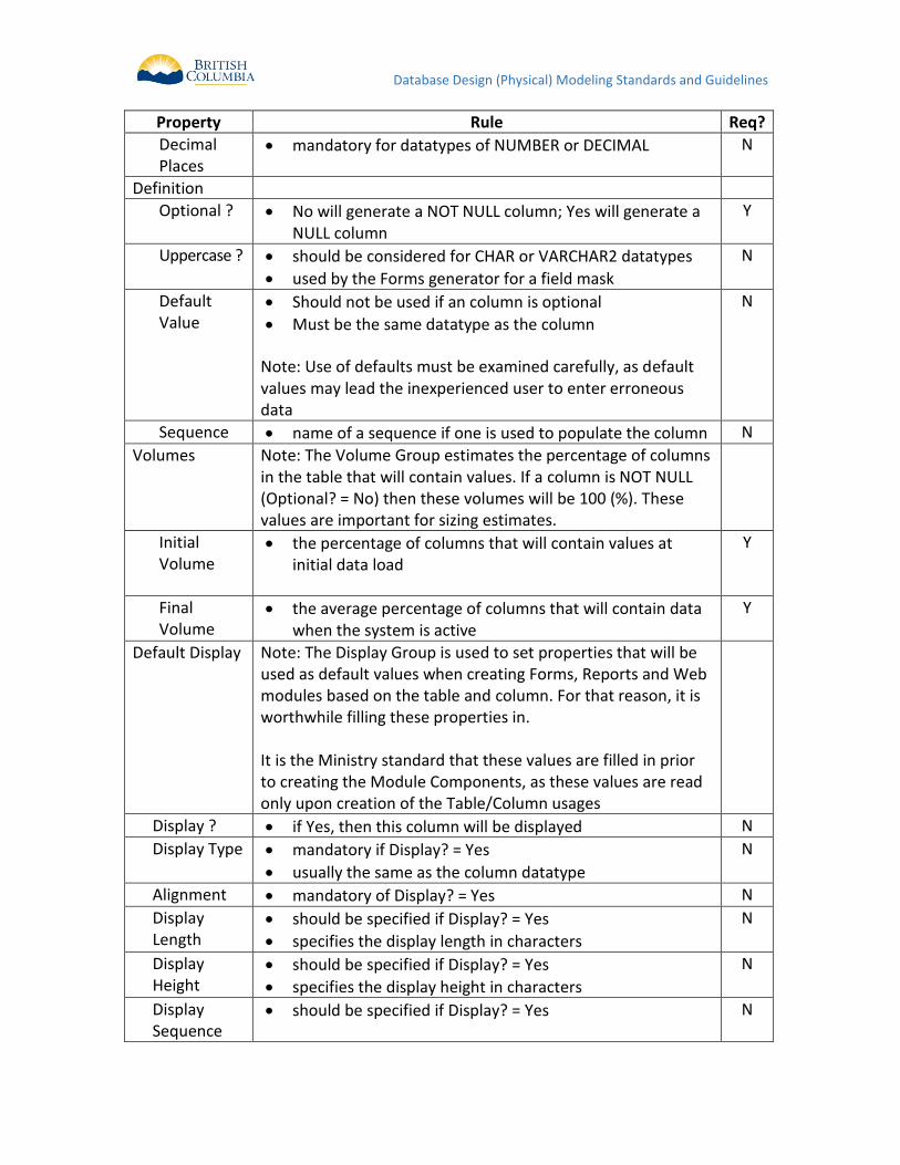
mandatory for datatypes of NUMBER or DECIMAL N
Definition
Optional ?
No will generate a NOT NULL column; Yes will generate a NULL column
Y
Uppercase ? should be considered for CHAR or VARCHAR2 datatypes
used by the Forms generator for a field mask
N
Default Value
Should not be used if an column is optional
Must be the same datatype as the column
Note: Use of defaults must be examined carefully, as default values may lead the inexperienced user to enter erroneous data
N
Sequence name of a sequence if one is used to populate the column N
Volumes Note: The Volume Group estimates the percentage of columns in the table that will contain values. If a column is NOT NULL (Optional? = No) then these volumes will be 100 (%). These values are important for sizing estimates.
Initial Volume
the percentage of columns that will contain values at initial data load
Y
Final Volume
the average percentage of columns that will contain data when the system is active
Y
Default Display Note: The Display Group is used to set properties that will be used as default values when creating Forms, Reports and Web modules based on the table and column. For that reason, it is worthwhile filling these properties in. It is the Ministry standard that these values are filled in prior to creating the Module Components, as these values are read only upon creation of the Table/Column usages
Display ? if Yes, then this column will be displayed N
Display Type mandatory if Display? = Yes
usually the same as the column datatype
N
Alignment mandatory of Display? = Yes N
Display Length
should be specified if Display? = Yes
specifies the display length in characters
N
Display Height
should be specified if Display? = Yes
specifies the display height in characters
N
Display Sequence
should be specified if Display? = Yes N
Database Design (Physical) Modeling Standards and Guidelines
Property Rule Req?
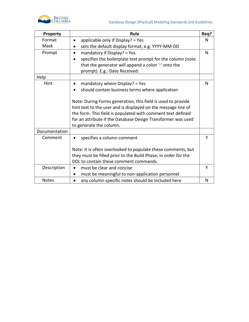
Format Mask
applicable only if Display? = Yes
sets the default display format, e.g. YYYY-MM-DD
N
Prompt mandatory if Display? = Yes
specifies the boilerplate text prompt for the column (note that the generator will append a colon ':' onto the prompt). E.g.: Date Received:
N
Help
Hint mandatory where Display? = Yes
should contain business terms where application
Note: During Forms generation, this field is used to provide hint text to the user and is displayed on the message line of the form. This field is populated with comment text defined for an attribute if the Database Design Transformer was used to generate the column.
N
Documentation
Comment
specifies a column comment
Note: It is often overlooked to populate these comments, but they must be filled prior to the Build Phase, in order for the DDL to contain these comment commands.
Y
Description must be clear and concise
must be meaningful to non-application personnel
Y
Notes any column-specific notes should be included here N
Database Design (Physical) Modeling Standards and Guidelines
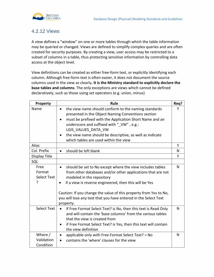
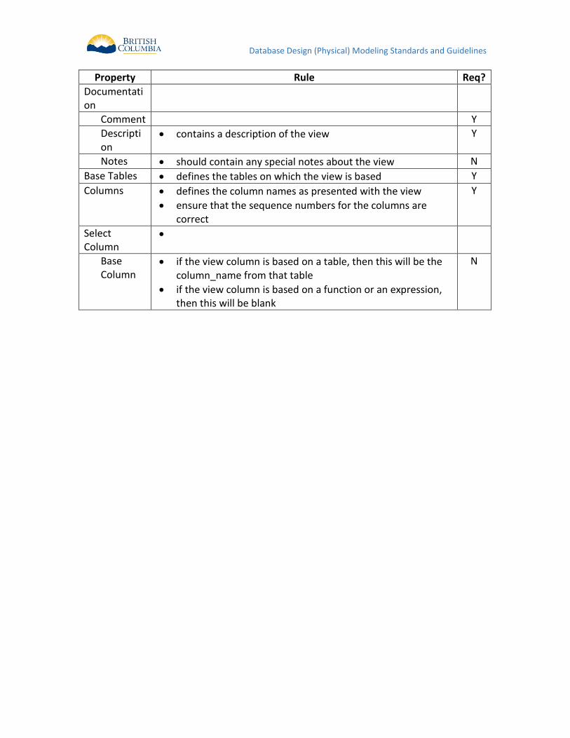
Views 4.2.12 A view defines a "window" on one or more tables through which the table information may be queried or changed. Views are defined to simplify complex queries and are often created for security purposes. By creating a view, user access may be restricted to a subset of columns in a table, thus protecting sensitive information by controlling data access at the object level. View definitions can be created as either free-form text, or explicitly identifying each column. Although free-form text is often easier, it does not document the source columns used in the view as clearly. It is the Ministry standard to explicitly declare the base tables and columns. The only exceptions are views which cannot be defined declaratively, such as those using set operators (e.g. union, minus)
Property Rule Req?
Name the view name should conform to the naming standards presented in the Object Naming Conventions section
must be prefixed with the Application Short Name and an underscore and suffixed with “_VW” , e.g.: LGIS_VALUES_DATA_VW
the view name should be descriptive, as well as indicate which tables are used within the view
Y
Alias Y
Col. Prefix should be left blank N
Display Title Y
SQL
Free Format Select Text ?
should be set to No except where the view includes tables from other databases and/or other applications that are not modeled in the repository
if a view is reverse engineered, then this will be Yes Caution: If you change the value of this property from Yes to No, you will lose any text that you have entered in the Select Text property.
N
Select Text if Free Format Select Text? is No, then this text is Read Only and will contain the 'base columns' from the various tables that the view is created from
if Free Format Select Text? is Yes, then this text will contain the view definition
N
Where / Validation Condition
applicable only with Free Format Select Text? = No
contains the 'where' clauses for the view
N
Database Design (Physical) Modeling Standards and Guidelines
Property Rule Req?
Documentation
Comment Y
Description
contains a description of the view Y
Notes should contain any special notes about the view N
Base Tables defines the tables on which the view is based Y
Columns defines the column names as presented with the view
ensure that the sequence numbers for the columns are correct
Y
Select Column
Base Column
if the view column is based on a table, then this will be the column_name from that table
if the view column is based on a function or an expression, then this will be blank
N
Database Design (Physical) Modeling Standards and Guidelines
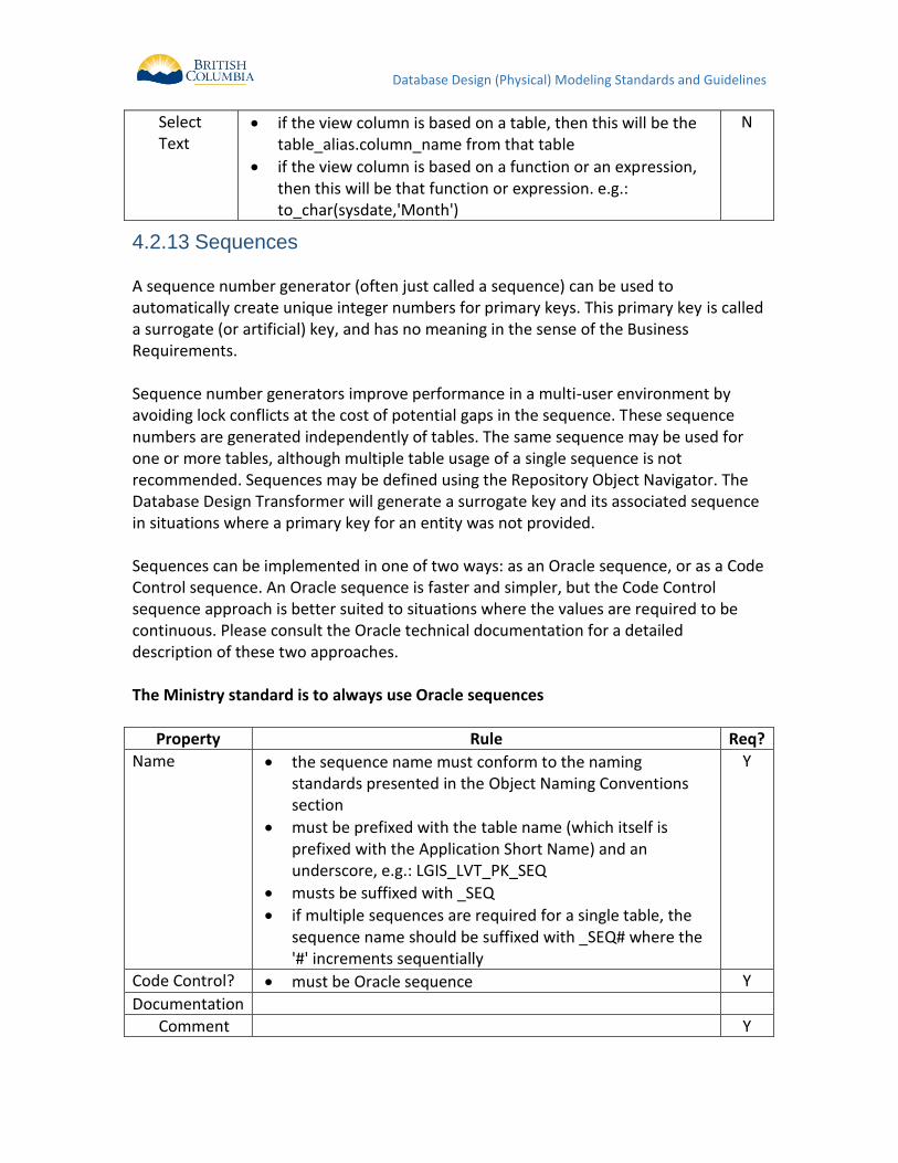
Select Text
if the view column is based on a table, then this will be the table_alias.column_name from that table
if the view column is based on a function or an expression, then this will be that function or expression. e.g.: to_char(sysdate,'Month')
N
Sequences 4.2.13 A sequence number generator (often just called a sequence) can be used to automatically create unique integer numbers for primary keys. This primary key is called a surrogate (or artificial) key, and has no meaning in the sense of the Business Requirements. Sequence number generators improve performance in a multi-user environment by avoiding lock conflicts at the cost of potential gaps in the sequence. These sequence numbers are generated independently of tables. The same sequence may be used for one or more tables, although multiple table usage of a single sequence is not recommended. Sequences may be defined using the Repository Object Navigator. The Database Design Transformer will generate a surrogate key and its associated sequence in situations where a primary key for an entity was not provided. Sequences can be implemented in one of two ways: as an Oracle sequence, or as a Code Control sequence. An Oracle sequence is faster and simpler, but the Code Control sequence approach is better suited to situations where the values are required to be continuous. Please consult the Oracle technical documentation for a detailed description of these two approaches. The Ministry standard is to always use Oracle sequences
Property Rule Req?
Name the sequence name must conform to the naming standards presented in the Object Naming Conventions section
must be prefixed with the table name (which itself is prefixed with the Application Short Name) and an underscore, e.g.: LGIS_LVT_PK_SEQ
musts be suffixed with _SEQ
if multiple sequences are required for a single table, the sequence name should be suffixed with _SEQ# where the '#' increments sequentially
Y
Code Control? must be Oracle sequence Y
Documentation
Comment Y
Database Design (Physical) Modeling Standards and Guidelines
Property Rule Req?
Description contains a description of the sequence Y
Notes contains any special notes on the sequence N
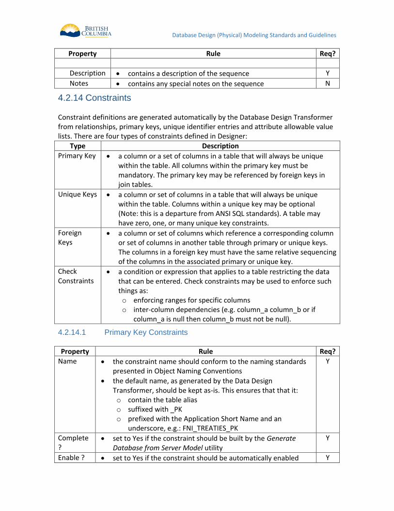
Constraints 4.2.14 Constraint definitions are generated automatically by the Database Design Transformer from relationships, primary keys, unique identifier entries and attribute allowable value lists. There are four types of constraints defined in Designer:
Type Description
Primary Key a column or a set of columns in a table that will always be unique within the table. All columns within the primary key must be mandatory. The primary key may be referenced by foreign keys in join tables.
Unique Keys a column or set of columns in a table that will always be unique within the table. Columns within a unique key may be optional (Note: this is a departure from ANSI SQL standards). A table may have zero, one, or many unique key constraints.
Foreign Keys
a column or set of columns which reference a corresponding column or set of columns in another table through primary or unique keys. The columns in a foreign key must have the same relative sequencing of the columns in the associated primary or unique key.
Check Constraints
a condition or expression that applies to a table restricting the data that can be entered. Check constraints may be used to enforce such things as: o enforcing ranges for specific columns o inter-column dependencies (e.g. column_a column_b or if
column_a is null then column_b must not be null).
Primary Key Constraints 4.2.14.1
Property Rule Req?
Name the constraint name should conform to the naming standards presented in Object Naming Conventions
the default name, as generated by the Data Design Transformer, should be kept as-is. This ensures that that it: o contain the table alias o suffixed with _PK o prefixed with the Application Short Name and an
underscore, e.g.: FNI_TREATIES_PK
Y
Complete ?
set to Yes if the constraint should be built by the Generate Database from Server Model utility
Y
Enable ? set to Yes if the constraint should be automatically enabled Y
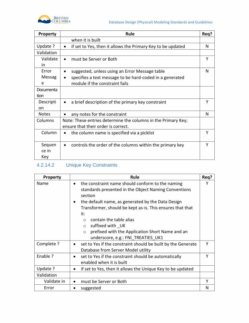
Database Design (Physical) Modeling Standards and Guidelines
Property Rule Req?
when it is built
Update ? if set to Yes, then it allows the Primary Key to be updated N
Validation
Validate in
must be Server or Both Y
Error Message
suggested, unless using an Error Message table
specifies a text message to be hard-coded in a generated module if the constraint fails
N
Documentation
Description
a brief description of the primary key constraint Y
Notes any notes for the constraint N
Columns Note: These entries determine the columns in the Primary Key; ensure that their order is correct.
Column
the column name is specified via a picklist Y
Sequence in Key
controls the order of the columns within the primary key Y
Unique Key Constraints 4.2.14.2
Property Rule Req?
Name the constraint name should conform to the naming standards presented in the Object Naming Conventions section
the default name, as generated by the Data Design Transformer, should be kept as-is. This ensures that that it: o contain the table alias o suffixed with _UK o prefixed with the Application Short Name and an
underscore, e.g.: FNI_TREATIES_UK1
Y
Complete ? set to Yes if the constraint should be built by the Generate Database from Server Model utility
Y
Enable ? set to Yes if the constraint should be automatically enabled when it is built
Y
Update ? if set to Yes, then it allows the Unique Key to be updated
Validation
Validate in must be Server or Both Y
Error suggested N
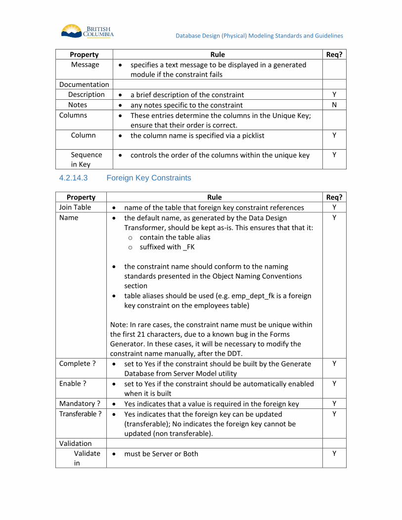
Database Design (Physical) Modeling Standards and Guidelines
Property Rule Req?
Message specifies a text message to be displayed in a generated module if the constraint fails
Documentation
Description a brief description of the constraint Y
Notes any notes specific to the constraint N
Columns These entries determine the columns in the Unique Key; ensure that their order is correct.
Column
the column name is specified via a picklist Y
Sequence in Key
controls the order of the columns within the unique key Y
Foreign Key Constraints 4.2.14.3
Property Rule Req?
Join Table name of the table that foreign key constraint references Y
Name the default name, as generated by the Data Design Transformer, should be kept as-is. This ensures that that it: o contain the table alias o suffixed with _FK
the constraint name should conform to the naming standards presented in the Object Naming Conventions section
table aliases should be used (e.g. emp_dept_fk is a foreign key constraint on the employees table)
Note: In rare cases, the constraint name must be unique within the first 21 characters, due to a known bug in the Forms Generator. In these cases, it will be necessary to modify the constraint name manually, after the DDT.
Y
Complete ? set to Yes if the constraint should be built by the Generate Database from Server Model utility
Y
Enable ? set to Yes if the constraint should be automatically enabled when it is built
Y
Mandatory ? Yes indicates that a value is required in the foreign key Y
Transferable ? Yes indicates that the foreign key can be updated (transferable); No indicates the foreign key cannot be updated (non transferable).
Y
Validation
Validate in
must be Server or Both Y
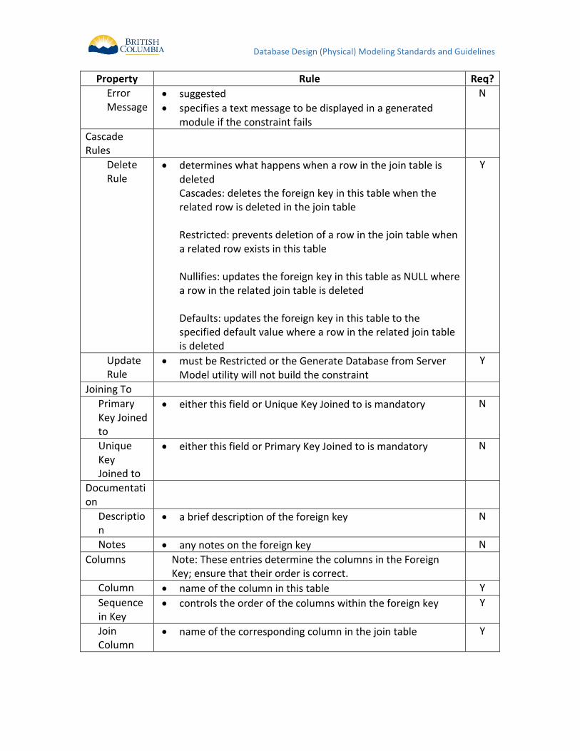
Database Design (Physical) Modeling Standards and Guidelines
Property Rule Req?
Error Message
suggested
specifies a text message to be displayed in a generated module if the constraint fails
N
Cascade Rules
Delete Rule
determines what happens when a row in the join table is deleted Cascades: deletes the foreign key in this table when the related row is deleted in the join table Restricted: prevents deletion of a row in the join table when a related row exists in this table Nullifies: updates the foreign key in this table as NULL where a row in the related join table is deleted Defaults: updates the foreign key in this table to the specified default value where a row in the related join table is deleted
Y
Update Rule
must be Restricted or the Generate Database from Server Model utility will not build the constraint
Y
Joining To
Primary Key Joined to
either this field or Unique Key Joined to is mandatory N
Unique Key Joined to
either this field or Primary Key Joined to is mandatory N
Documentation
Description
a brief description of the foreign key N
Notes any notes on the foreign key N
Columns Note: These entries determine the columns in the Foreign Key; ensure that their order is correct.
Column name of the column in this table Y
Sequence in Key
controls the order of the columns within the foreign key Y
Join Column
name of the corresponding column in the join table Y
Database Design (Physical) Modeling Standards and Guidelines
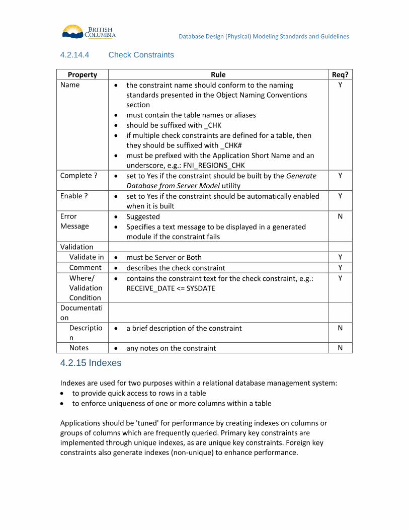
Check Constraints 4.2.14.4
Property Rule Req?
Name the constraint name should conform to the naming standards presented in the Object Naming Conventions section
must contain the table names or aliases
should be suffixed with _CHK
if multiple check constraints are defined for a table, then they should be suffixed with _CHK#
must be prefixed with the Application Short Name and an underscore, e.g.: FNI_REGIONS_CHK
Y
Complete ? set to Yes if the constraint should be built by the Generate Database from Server Model utility
Y
Enable ? set to Yes if the constraint should be automatically enabled when it is built
Y
Error Message
Suggested
Specifies a text message to be displayed in a generated module if the constraint fails
N
Validation
Validate in must be Server or Both Y
Comment describes the check constraint Y
Where/ Validation Condition
contains the constraint text for the check constraint, e.g.: RECEIVE_DATE <= SYSDATE
Y
Documentation
Description
a brief description of the constraint N
Notes any notes on the constraint N
Indexes 4.2.15 Indexes are used for two purposes within a relational database management system:
to provide quick access to rows in a table
to enforce uniqueness of one or more columns within a table Applications should be 'tuned' for performance by creating indexes on columns or groups of columns which are frequently queried. Primary key constraints are implemented through unique indexes, as are unique key constraints. Foreign key constraints also generate indexes (non-unique) to enhance performance.
Database Design (Physical) Modeling Standards and Guidelines
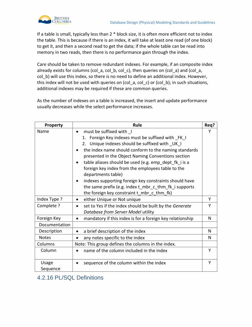
If a table is small, typically less than 2 * block size, it is often more efficient not to index the table. This is because if there is an index, it will take at least one read (of one block) to get it, and then a second read to get the data; if the whole table can be read into memory in two reads, then there is no performance gain through the index. Care should be taken to remove redundant indexes. For example, if an composite index already exists for columns (col_a, col_b, col_c), then queries on (col_a) and (col_a, col_b) will use this index, so there is no need to define an additional index. However, this index will not be used with queries on (col_a, col_c) or (col_b); in such situations, additional indexes may be required if these are common queries. As the number of indexes on a table is increased, the insert and update performance usually decreases while the select performance increases.
Property Rule Req?
Name must be suffixed with _I 1. Foreign Key indexes must be suffixed with _FK_I 2. Unique indexes should be suffixed with _UK_I
the index name should conform to the naming standards presented in the Object Naming Conventions section
table aliases should be used (e.g. emp_dept_fk_i is a foreign key index from the employees table to the departments table)
indexes supporting foreign key constraints should have the same prefix (e.g. index t_mbr_c_thm_fk_i supports the foreign key constraint t_mbr_c_thm_fk)
Y
Index Type ? either Unique or Not unique Y
Complete ? set to Yes if the index should be built by the Generate Database from Server Model utility
Y
Foreign Key mandatory if this index is for a foreign key relationship N
Documentation
Description a brief description of the index N
Notes any notes specific to the index N
Columns Note: This group defines the columns in the index.
Column
name of the column included in the index Y
Usage Sequence
sequence of the column within the index Y
PL/SQL Definitions 4.2.16
Database Design (Physical) Modeling Standards and Guidelines
Best Practices for Coding 4.2.16.1
The intent of this section is to describe best practices when coding PL/SQL in the Oracle database. This applies only to new applications, and as per Ministry standards, the PL/SQL must be documented in the Designer Repository. These best practices are simple and practical guidelines for developers. The objective of these best practices is to produce PL/SQL code that is understandable and maintainable. Much of the content in this section is derived from Steven Feurestein’s book “Oracle PL/SQL Programming1” and on-line articles.
Follow Ministry Coding Standards 4.2.16.1.1
In addition to the Designer-specific guidelines in this document, PL/SQL Developers should follow the Ministry’s “Standardized Coding Practices”. Some of these practices, such as Variable Type Prefixes, are not relevant to PL/SQL but the following do apply:
Variable Scope and Usage Prefixes (e.g. g_, st_, v_, etc.)
Variable Name Capitalization (i.e. camelCase) ; although camel_Case (with
underscores) are also permissible if this aids readability
Constants (i.e. all uppercase)
Comments (comment code blocks that are large or complex)
Readability (indenting code and using whitespace); there are no explicitly
rules to indentation and whitespace (i.e. leading tab characters, or ‘four
spaces’), so the key best practice here is consistency within the application.
Use Packages instead of stand-alone procedures or 4.2.16.1.2functions
Organize all PL/SQL code in well-named packages, which has the following advantages over stand-alone modules:
breaks the dependency chain in that there are no cascading invalidations
when you install a new package body. If you have procedures that call other
procedures, then compiling one will invalidate your code.
supports encapsulation -- allows you to write modular, easy to understand
code -- rather then monolithic, hard to read procedures
increases your namespace measurably. Package names have to be unique in
1 Oracle PL/SQL Programming, Third Edition, by Steven Feurstein with Bill Pribyl, 2002, O’Reilly &
Associates, Inc.
Database Design (Physical) Modeling Standards and Guidelines
a schema, so you can have many procedures across different packages with
the same name without colliding.
supports overloading
supports session variables when you need them
promote overall good coding techniques by logically grouping related code
Use Anchored Declarations 4.2.16.1.3
In retrieving the value of a column, it is possible to declare the variables as a generic numeric or character (i.e. party_id IN number). However, it is better to anchor the declaration to the underlying datatype in the column (i.e. party_id party.id%TYPE). This ensures that the variable will be able to hold the value, even if the column’s datatype changes in the future.
Avoid Repetition of SQL Code 4.2.16.1.4
Instead of embedding native SQL code everywhere, the SQL statements should be encapsulated into a central PL/SQL function. Typically, there is a central function for every table, or set of tables acting as a common interface (e.g. PARTY, NAME, ADDRESS are normalized tables that often are queried at the same time). This also applies to SELECT’s, INSERT’s, UPDATE’s, and DELETE’s. This “central PL/SQL function” should be a pre-built, pre-tested module that allows it to be ‘written once, used often’ .
Avoid excessively long procedures or functions 4.2.16.1.5
Use local procedures and functions to hide logic from the ‘mainline’ portion of the module, breaking up the larger problem into smaller, more manageable problems. This will result in more small, focused packages. Each of these will have executable sections that are smaller, readable and less than 75 lines from BEGIN to END.
Use Bind Variables instead of string literals 4.2.16.1.6
Instead of concatenating strings together (i.e. user = ‘&User’) to build a SQL query, it is better to use bind variables (i.e. user = :user). This is important in terms of scalability and performance, but it is especially important to help prevent against SQL injection attacks. For more details on SQL injection, see “Effective Oracle by Design” by Thomas Kyte (ISBN number 0072230657).

Database Design (Physical) Modeling Standards and Guidelines
Formalize Unit Testing 4.2.16.1.7
Unit Testing should incorporate documented test cases, and any bugs discovered should reference this test case. It is recommended that a testing framework be established and used. Two examples are Oracle Unit Tester (http://www.ounit.com/) and Unit Testing Framework for PL/SQL Developers (http://oracle.oreilly.com/utplsql/).
Function, Packages, Procedures, and Cursors 4.2.16.1.8
PL/SQL Definitions are components of the application that are stored in the database. Naming conventions for triggers are described in the appropriate Database Design section. Names for these:
should be no more than 30 characters long
must contain the Application Short Name and an underscore as a prefix, unless the program is inside a package
must be suffixed with an underscore and a type (unless it is inside a package): _PKG for packages _F for functions _P for procedures _CSR for cursors
the centre component of the name is a free format descriptive identified that follows general naming conventions where possible (see Object Naming Conventions for database objects)
example: STVS_STANDARD_PKG- a package of functions. PL/SQL Definitions can be declarative (e.g. every variable, constant, argument, etceteras is defined and recorded as an object in the repository) or free format (e.g. all code and variable declarations are recorded as part of a multi-line text property in the repository.
Database Design (Physical) Modeling Standards and Guidelines
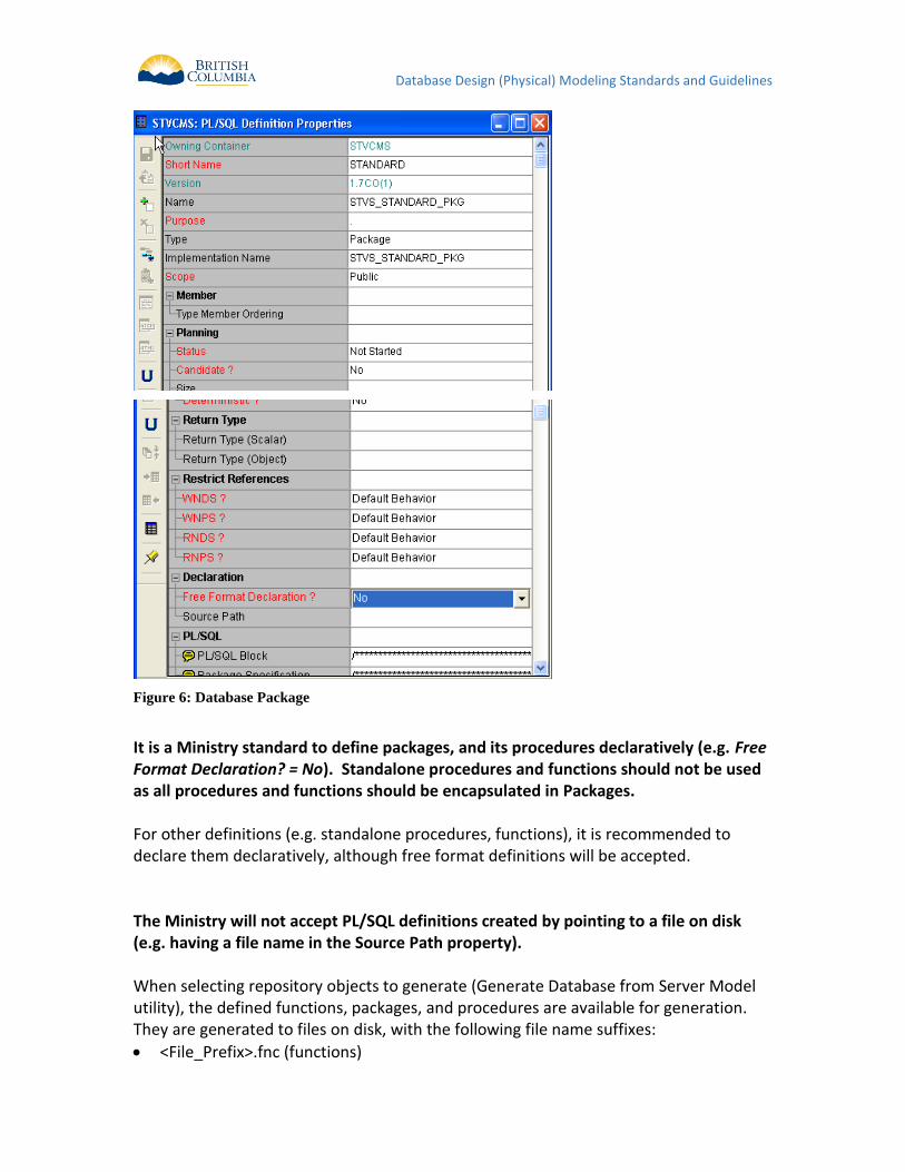
Figure 6: Database Package
It is a Ministry standard to define packages, and its procedures declaratively (e.g. Free Format Declaration? = No). Standalone procedures and functions should not be used as all procedures and functions should be encapsulated in Packages. For other definitions (e.g. standalone procedures, functions), it is recommended to declare them declaratively, although free format definitions will be accepted. The Ministry will not accept PL/SQL definitions created by pointing to a file on disk (e.g. having a file name in the Source Path property). When selecting repository objects to generate (Generate Database from Server Model utility), the defined functions, packages, and procedures are available for generation. They are generated to files on disk, with the following file name suffixes:
<File_Prefix>.fnc (functions)
Database Design (Physical) Modeling Standards and Guidelines
<File_Prefix>.pks (package specifications)
<File_Prefix>.pkb (package body specifications)
<File_Prefix>.prc (procedures) Note: Included procedures and functions (e.g. inside a package) are always generated in the context of the owning package definition and are not available for selection under the Procedure and Function nodes when you generate the package.
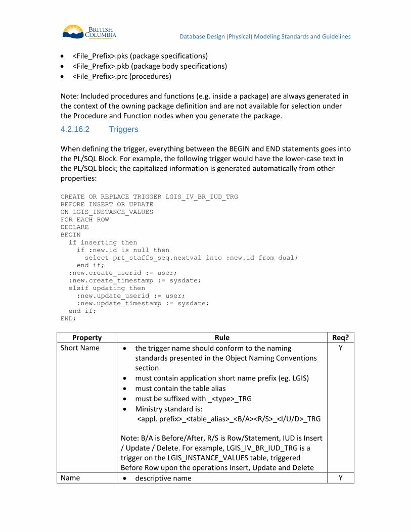
Triggers 4.2.16.2
When defining the trigger, everything between the BEGIN and END statements goes into the PL/SQL Block. For example, the following trigger would have the lower-case text in the PL/SQL block; the capitalized information is generated automatically from other properties: CREATE OR REPLACE TRIGGER LGIS_IV_BR_IUD_TRG
BEFORE INSERT OR UPDATE
ON LGIS_INSTANCE_VALUES
FOR EACH ROW
DECLARE
BEGIN
if inserting then
if :new.id is null then
select prt_staffs_seq.nextval into :new.id from dual;
end if;
:new.create_userid := user;
:new.create_timestamp := sysdate;
elsif updating then
:new.update_userid := user;
:new.update_timestamp := sysdate;
end if;
END;
Property Rule Req?
Short Name the trigger name should conform to the naming standards presented in the Object Naming Conventions section
must contain application short name prefix (eg. LGIS)
must contain the table alias
must be suffixed with _<type>_TRG
Ministry standard is: <appl. prefix>_<table_alias>_<B/A><R/S>_<I/U/D>_TRG
Note: B/A is Before/After, R/S is Row/Statement, IUD is Insert / Update / Delete. For example, LGIS_IV_BR_IUD_TRG is a trigger on the LGIS_INSTANCE_VALUES table, triggered Before Row upon the operations Insert, Update and Delete
Y
Name descriptive name Y
Database Design (Physical) Modeling Standards and Guidelines
Property Rule Req?
Purpose short description for the purpose of the trigger Y
Type must be set to Trg-Logic Y
Implementation Name
recommended to leave blank, so that implementation name is derived from the Short Name
N
PL/SQL
PL/SQL Block
contains the body of the trigger (everything between the BEGIN and END statements - see example)
Y
Documentation
Module Generation History
must contain dates, names and brief descriptions for each major modification of the module
historical information must be maintained
Y
Release Notes
optional
any release-specific information for the current version
N
Description optional
a brief description of the trigger
N
Notes any notes about the trigger N
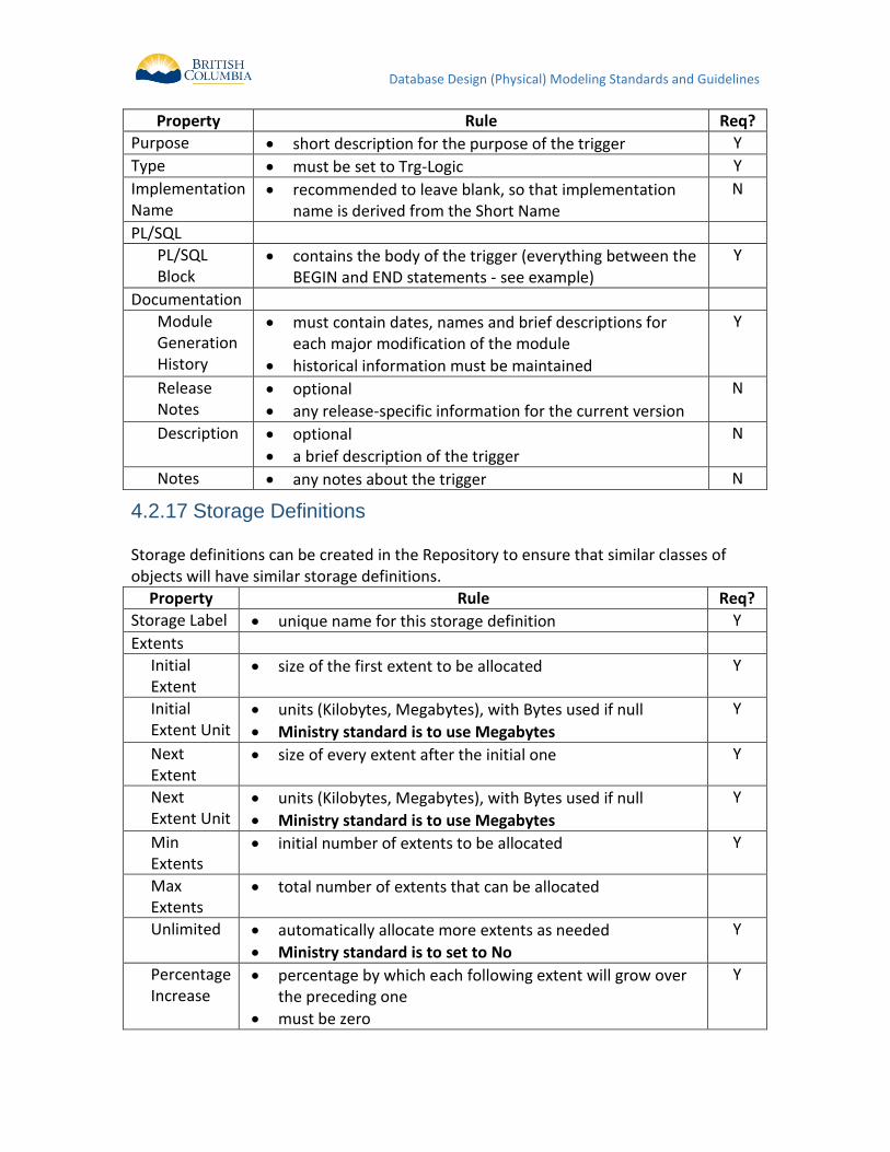
Storage Definitions 4.2.17 Storage definitions can be created in the Repository to ensure that similar classes of objects will have similar storage definitions.
Property Rule Req?
Storage Label unique name for this storage definition Y
Extents
Initial Extent
size of the first extent to be allocated Y
Initial Extent Unit
units (Kilobytes, Megabytes), with Bytes used if null
Ministry standard is to use Megabytes
Y
Next Extent
size of every extent after the initial one Y
Next Extent Unit
units (Kilobytes, Megabytes), with Bytes used if null
Ministry standard is to use Megabytes
Y
Min Extents
initial number of extents to be allocated Y
Max Extents
total number of extents that can be allocated
Unlimited automatically allocate more extents as needed
Ministry standard is to set to No
Y
Percentage Increase
percentage by which each following extent will grow over the preceding one
must be zero
Y
Database Design (Physical) Modeling Standards and Guidelines
Synonyms 4.2.18 Public Synonyms can be defined in the Repository and created with the Generate Database from Server Model utility. The Synonyms Group underneath the object in each of the Modules, Tables, Sequences and Views nodes is used for this. The Public Synonym Name must match exactly the object name that it references (e.g. LGIS_FIELD_GROUPS public synonym for the LGIS_FIELD_GROUPS table).
Database Object Grants 4.2.19 Privileges on database objects granted to roles must also be captured, documented and maintained in the Designer Repository. Once the roles and the actual objects exist, the Database Object Grants group for each object is used to grant the specific privileges to the various roles. Roles must be hierarchical. Therefore one should only grant the additional rights specific to that role to an object. For example, assume that there are three roles: APPL_ROLE_1, APPL_ROLE_2 and APPL_ROLE_3. APPL_ROLE_1 is granted to APPL_ROLE_2, and APPL_ROLE_2 is granted to APPL_ROLE_3. For a specific table APPL_ROLE_1 needs select, APPL_ROLE_2 needs select and insert, and APPL_ROLE_3 requires select, insert and delete. Instead of explicitly granting all the rights for the table to each role, the Ministry standard is to:
SELECT to APPL_ROLE_1
INSERT to APPL_ROLE_2
DELETE to APPL_ROLE_3 and ensure that the role hierarchies are defined and granted correctly A further example follows, from the Oracle 11g Database Security Guide (Figure 21-1):
Database Design (Physical) Modeling Standards and Guidelines
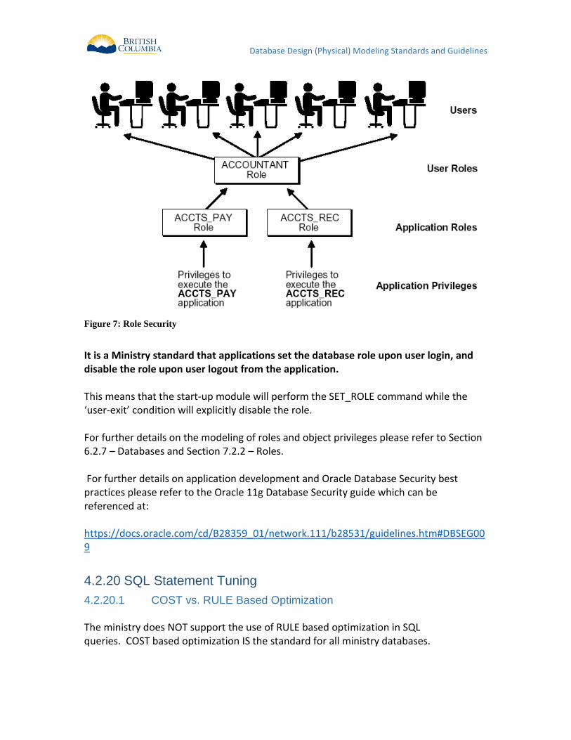
Figure 7: Role Security
It is a Ministry standard that applications set the database role upon user login, and disable the role upon user logout from the application. This means that the start-up module will perform the SET_ROLE command while the ‘user-exit’ condition will explicitly disable the role. For further details on the modeling of roles and object privileges please refer to Section 6.2.7 – Databases and Section 7.2.2 – Roles. For further details on application development and Oracle Database Security best practices please refer to the Oracle 11g Database Security guide which can be referenced at: https://docs.oracle.com/cd/B28359_01/network.111/b28531/guidelines.htm#DBSEG009
SQL Statement Tuning 4.2.20
COST vs. RULE Based Optimization 4.2.20.1
The ministry does NOT support the use of RULE based optimization in SQL queries. COST based optimization IS the standard for all ministry databases.
Database Design (Physical) Modeling Standards and Guidelines
The primary reasons for this are that the RULE based optimizer has been de-supported in the Oracle RDBMS (after 11gi Release 1), and it is more expensive to maintain queries developed using RULE’s due to changes in data content and selectivity over time. As well, a properly designed data structure and efficient SQL will ensure that COST based optimization provides the most efficient data access paths.
Explain Plans 4.2.20.2
Every static multi join query (2 or more tables) must provide EXPLAIN PLAN output. Developers should make available suitable data volumes for testing purposes in order for the explain plan to be properly utilized. Ensure that prior to generating the explain plans that table and index statistics are updated, as this will influence optimizer behavior. There are standard Oracle supplied packages which simplify this process for developers and the DBA, such as: EXEC DBMS_UTILITY.ANALYZE_SCHEMA('SCHEMA_NAME','COMPUTE');
NOTE: For more information on SQL Statement Tuning and general Oracle tuning considerations please reference the Oracle 11g server documentation available from Oracle's technical support website (support.oracle.com)
Embedding of SQL in PL/SQL Code 4.2.20.3
As discussed in “4.2.16.1.4 Avoid Repetition of SQL Code”, it is a PL/SQL Best Practice to use centralized data access in PL/SQL functions that also includes all of the necessary error handling and optimization logic. This is in contrast to “SELECT INTO…” statements in multiple places, all accessing the same table or view, but using different variable names or types. This results in excessive parsing and difficulty in optimizing the performance. The database can take advantage of cached statements if the syntax of the statement is exactly the same; this enables more code re-use and better optimization.
5 BUILD PHASE
5.1 OVERALL GUIDELINES This section presents some overall guidelines to assist in application development within the Oracle Designer environment.
Referencing Objects in Text Descriptions 5.1.1 Whenever the name of another TABLE, COLUMN (or any other object) is used within a textual description, it should be capitalized for easier reading (and reference).
Database Design (Physical) Modeling Standards and Guidelines
For example, if WRQ_LAB_NO is a column, then the following notes should be used for the LGIS_FIELD_GROUPS table: "This table has a one-way link to the WRQ system, via the shared identifier WRQ_LAB_NO" Note: This may make maintenance of this text difficult, as changes in table or column names would necessitate updates to the descriptive text. Therefore, this is a recommended guideline, and not a Ministry standard.
Keeping logical and physical data models current 5.1.2 In the Build Phase, there may be corrections and/or additions to the data requirements (i.e. revised column definition). Aside from de-normalization or other issues specific to physical implementation, all such changes must be re-documented in the logical data model via manual update of entities, attributes and relationships If the application was not developed using Designer10g it may be permissible to reverse engineer the model into Designer via the Table to Entity Retrofit Utility. See Synchronizing Entities with Tables for further information on the Table to Entity Retrofit Utility.
Documenting Post-Generation Changes 5.1.3 All post-generation module changes (aside from layout modifications) must be documented in the repository, either via a Capture Design or via text in the Module Notes. All changes to database objects must be performed via the repository. Database objects (other than modules) must not be updated directly in the target database, but instead will be updated in the Designer 10g repository and pushed out to the target DB via the CD promotion model. Electronic Delivery of the Application All development is done directly against the Ministry Repository, so no explicit delivery is required. If an alternative toolset is chosen, delivery of any models or reports will be checked into the Ministries SCM Repository as outline within the Application’s Project Management timelines for review by the Ministry’s ISB staff.
Database Design (Physical) Modeling Standards and Guidelines
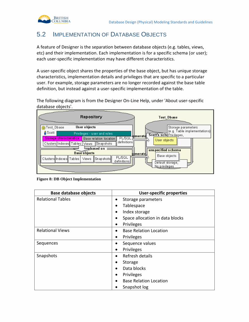
5.2 IMPLEMENTATION OF DATABASE OBJECTS A feature of Designer is the separation between database objects (e.g. tables, views, etc) and their implementation. Each implementation is for a specific schema (or user); each user-specific implementation may have different characteristics. A user-specific object shares the properties of the base object, but has unique storage characteristics, implementation details and privileges that are specific to a particular user. For example, storage parameters are no longer recorded against the base table definition, but instead against a user-specific implementation of the table. The following diagram is from the Designer On-Line Help, under 'About user-specific database objects'.
Figure 8: DB Object Implementation
Base database objects User-specific properties
Relational Tables Storage parameters
Tablespace
Index storage
Space allocation in data blocks
Privileges
Relational Views Base Relation Location
Privileges
Sequences Sequence values
Privileges
Snapshots Refresh details
Storage
Data blocks
Privileges
Base Relation Location
Snapshot log
Database Design (Physical) Modeling Standards and Guidelines
Base database objects User-specific properties
PL/SQL Definitions (e.g. Functions, Procedures, and Packages)
Privileges
Object Tables Tablespace
Index storage
Space allocation in data blocks
Privileges
Object Views Base Relation Location
Privileges
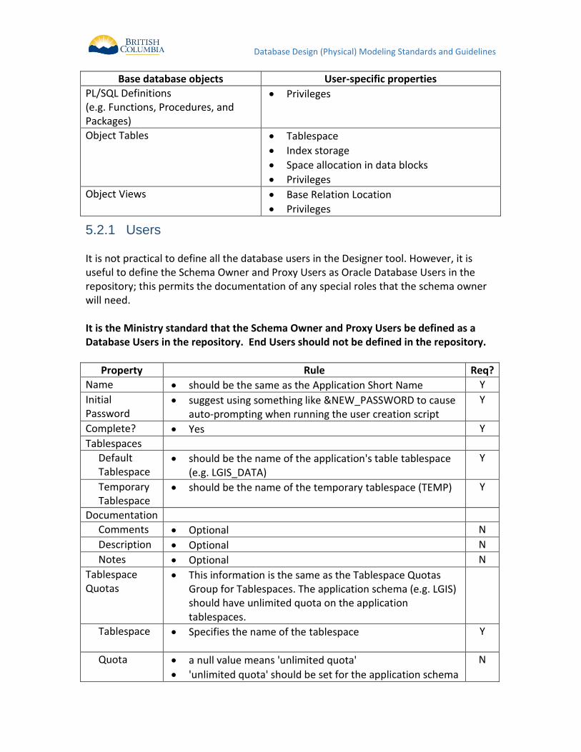
Users 5.2.1 It is not practical to define all the database users in the Designer tool. However, it is useful to define the Schema Owner and Proxy Users as Oracle Database Users in the repository; this permits the documentation of any special roles that the schema owner will need. It is the Ministry standard that the Schema Owner and Proxy Users be defined as a Database Users in the repository. End Users should not be defined in the repository.
Property Rule Req?
Name should be the same as the Application Short Name Y
Initial Password
suggest using something like &NEW_PASSWORD to cause auto-prompting when running the user creation script
Y
Complete? Yes Y
Tablespaces
Default Tablespace
should be the name of the application's table tablespace (e.g. LGIS_DATA)
Y
Temporary Tablespace
should be the name of the temporary tablespace (TEMP) Y
Documentation
Comments Optional N
Description Optional N
Notes Optional N
Tablespace Quotas
This information is the same as the Tablespace Quotas Group for Tablespaces. The application schema (e.g. LGIS) should have unlimited quota on the application tablespaces.
Tablespace
Specifies the name of the tablespace Y
Quota a null value means 'unlimited quota'
'unlimited quota' should be set for the application schema
N
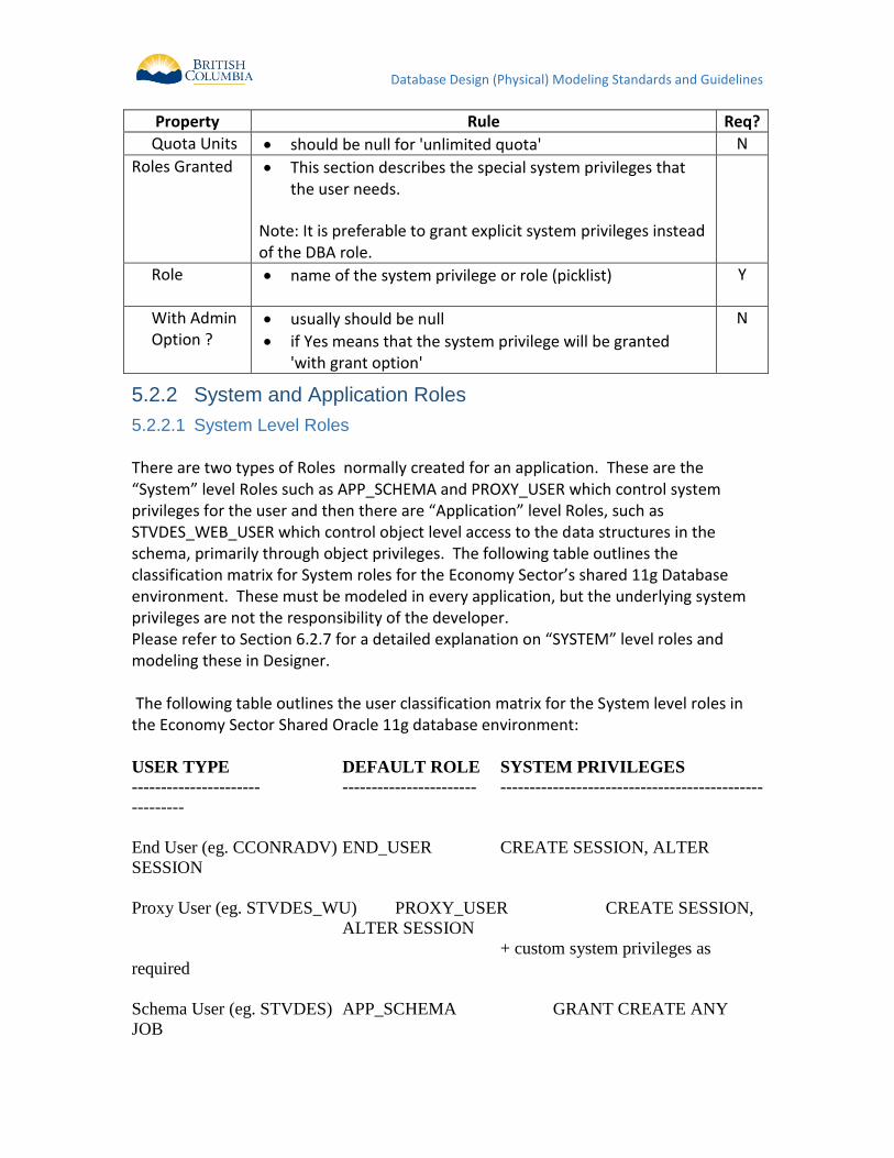
Database Design (Physical) Modeling Standards and Guidelines
Property Rule Req?
Quota Units should be null for 'unlimited quota' N
Roles Granted This section describes the special system privileges that the user needs.
Note: It is preferable to grant explicit system privileges instead of the DBA role.
Role
name of the system privilege or role (picklist) Y
With Admin Option ?
usually should be null
if Yes means that the system privilege will be granted 'with grant option'
N
System and Application Roles 5.2.2
System Level Roles 5.2.2.1
There are two types of Roles normally created for an application. These are the “System” level Roles such as APP_SCHEMA and PROXY_USER which control system privileges for the user and then there are “Application” level Roles, such as STVDES_WEB_USER which control object level access to the data structures in the schema, primarily through object privileges. The following table outlines the classification matrix for System roles for the Economy Sector’s shared 11g Database environment. These must be modeled in every application, but the underlying system privileges are not the responsibility of the developer. Please refer to Section 6.2.7 for a detailed explanation on “SYSTEM” level roles and modeling these in Designer. The following table outlines the user classification matrix for the System level roles in the Economy Sector Shared Oracle 11g database environment: USER TYPE DEFAULT ROLE SYSTEM PRIVILEGES ---------------------- ----------------------- ---------------------------------------------
---------
End User (eg. CCONRADV) END_USER CREATE SESSION, ALTER
SESSION
Proxy User (eg. STVDES_WU) PROXY_USER CREATE SESSION,
ALTER SESSION
+ custom system privileges as
required
Schema User (eg. STVDES) APP_SCHEMA GRANT CREATE ANY
JOB
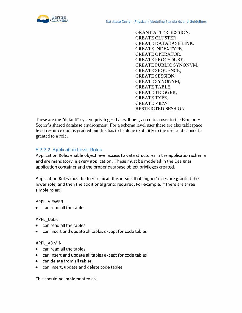
Database Design (Physical) Modeling Standards and Guidelines
GRANT ALTER SESSION,
CREATE CLUSTER,
CREATE DATABASE LINK,
CREATE INDEXTYPE,
CREATE OPERATOR,
CREATE PROCEDURE,
CREATE PUBLIC SYNONYM,
CREATE SEQUENCE,
CREATE SESSION,
CREATE SYNONYM,
CREATE TABLE,
CREATE TRIGGER,
CREATE TYPE,
CREATE VIEW,
RESTRICTED SESSION
These are the "default" system privileges that will be granted to a user in the Economy
Sector’s shared database environment. For a schema level user there are also tablespace
level resource quotas granted but this has to be done explicitly to the user and cannot be
granted to a role.
Application Level Roles 5.2.2.2
Application Roles enable object level access to data structures in the application schema and are mandatory in every application. These must be modeled in the Designer application container and the proper database object privileges created. Application Roles must be hierarchical; this means that 'higher' roles are granted the lower role, and then the additional grants required. For example, if there are three simple roles: APPL_VIEWER
can read all the tables APPL_USER
can read all the tables
can insert and update all tables except for code tables APPL_ADMIN
can read all the tables
can insert and update all tables except for code tables
can delete from all tables
can insert, update and delete code tables This should be implemented as:
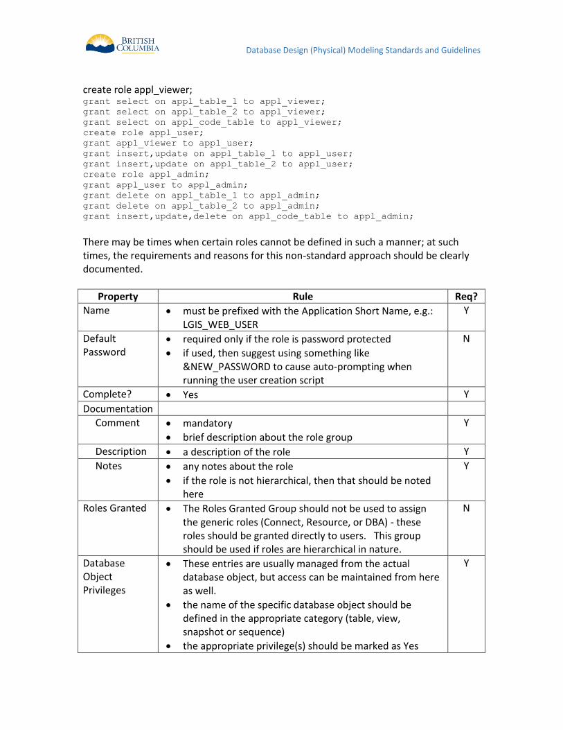
Database Design (Physical) Modeling Standards and Guidelines
create role appl_viewer; grant select on appl_table_1 to appl_viewer;
grant select on appl_table_2 to appl_viewer;
grant select on appl_code_table to appl_viewer;
create role appl_user;
grant appl_viewer to appl_user;
grant insert,update on appl_table_1 to appl_user;
grant insert,update on appl_table_2 to appl_user;
create role appl_admin;
grant appl_user to appl_admin;
grant delete on appl_table_1 to appl_admin;
grant delete on appl_table_2 to appl_admin;
grant insert,update,delete on appl_code_table to appl_admin;
There may be times when certain roles cannot be defined in such a manner; at such times, the requirements and reasons for this non-standard approach should be clearly documented.
Property Rule Req?
Name must be prefixed with the Application Short Name, e.g.: LGIS_WEB_USER
Y
Default Password
required only if the role is password protected
if used, then suggest using something like &NEW_PASSWORD to cause auto-prompting when running the user creation script
N
Complete? Yes Y
Documentation
Comment
mandatory
brief description about the role group
Y
Description a description of the role Y
Notes any notes about the role
if the role is not hierarchical, then that should be noted here
Y
Roles Granted The Roles Granted Group should not be used to assign the generic roles (Connect, Resource, or DBA) - these roles should be granted directly to users. This group should be used if roles are hierarchical in nature.
N
Database Object Privileges
These entries are usually managed from the actual database object, but access can be maintained from here as well.
the name of the specific database object should be defined in the appropriate category (table, view, snapshot or sequence)
the appropriate privilege(s) should be marked as Yes
Y
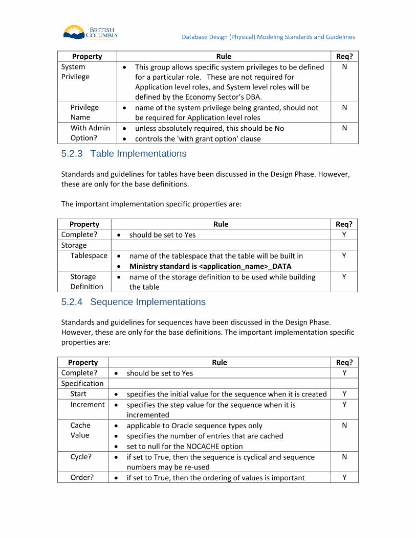
Database Design (Physical) Modeling Standards and Guidelines
Property Rule Req?
System Privilege
This group allows specific system privileges to be defined for a particular role. These are not required for Application level roles, and System level roles will be defined by the Economy Sector’s DBA.
N
Privilege Name
name of the system privilege being granted, should not be required for Application level roles
N
With Admin Option?
unless absolutely required, this should be No
controls the 'with grant option' clause
N
Table Implementations 5.2.3 Standards and guidelines for tables have been discussed in the Design Phase. However, these are only for the base definitions. The important implementation specific properties are:
Property Rule Req?
Complete? should be set to Yes Y
Storage
Tablespace
name of the tablespace that the table will be built in
Ministry standard is <application_name>_DATA
Y
Storage Definition
name of the storage definition to be used while building the table
Y
Sequence Implementations 5.2.4 Standards and guidelines for sequences have been discussed in the Design Phase. However, these are only for the base definitions. The important implementation specific properties are:
Property Rule Req?
Complete? should be set to Yes Y
Specification
Start specifies the initial value for the sequence when it is created Y
Increment specifies the step value for the sequence when it is incremented
Y
Cache Value
applicable to Oracle sequence types only
specifies the number of entries that are cached
set to null for the NOCACHE option
N
Cycle? if set to True, then the sequence is cyclical and sequence numbers may be re-used
N
Order? if set to True, then the ordering of values is important Y
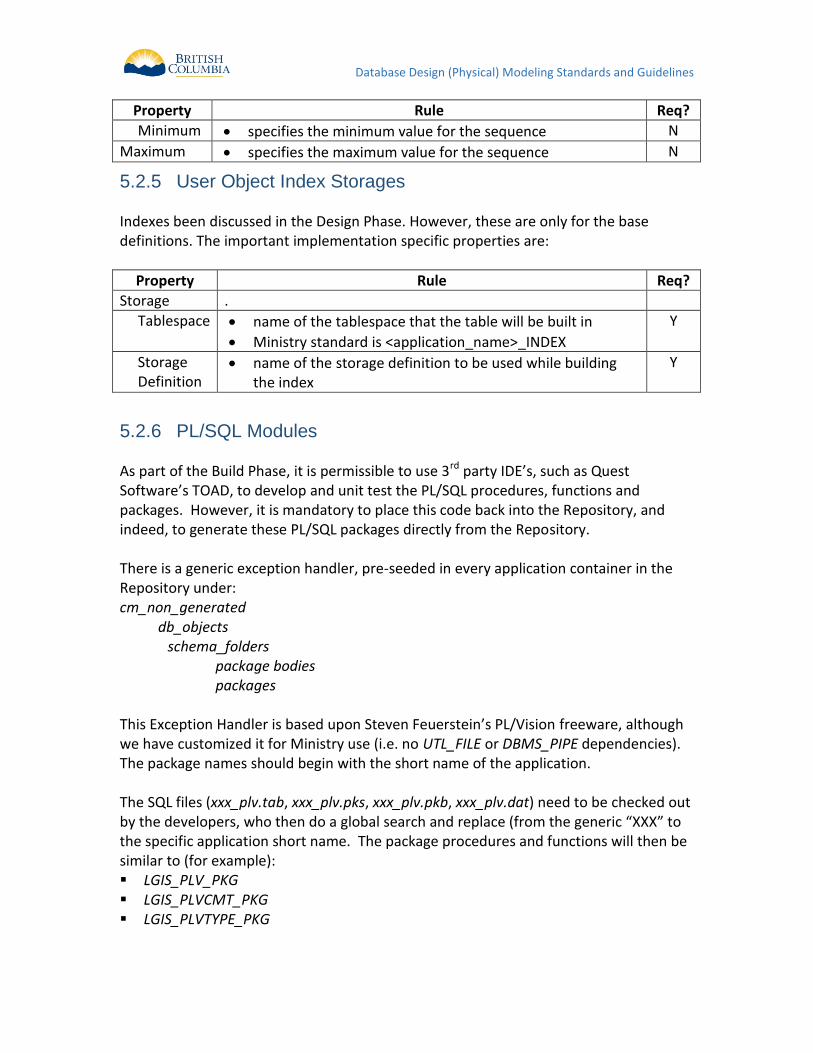
Database Design (Physical) Modeling Standards and Guidelines
Property Rule Req?
Minimum specifies the minimum value for the sequence N
Maximum specifies the maximum value for the sequence N
User Object Index Storages 5.2.5 Indexes been discussed in the Design Phase. However, these are only for the base definitions. The important implementation specific properties are:
Property Rule Req?
Storage .
Tablespace
name of the tablespace that the table will be built in
Ministry standard is <application_name>_INDEX
Y
Storage Definition
name of the storage definition to be used while building the index
Y
PL/SQL Modules 5.2.6 As part of the Build Phase, it is permissible to use 3rd party IDE’s, such as Quest Software’s TOAD, to develop and unit test the PL/SQL procedures, functions and packages. However, it is mandatory to place this code back into the Repository, and indeed, to generate these PL/SQL packages directly from the Repository. There is a generic exception handler, pre-seeded in every application container in the Repository under: cm_non_generated
db_objects schema_folders package bodies packages
This Exception Handler is based upon Steven Feuerstein’s PL/Vision freeware, although we have customized it for Ministry use (i.e. no UTL_FILE or DBMS_PIPE dependencies). The package names should begin with the short name of the application. The SQL files (xxx_plv.tab, xxx_plv.pks, xxx_plv.pkb, xxx_plv.dat) need to be checked out by the developers, who then do a global search and replace (from the generic “XXX” to the specific application short name. The package procedures and functions will then be similar to (for example): LGIS_PLV_PKG LGIS_PLVCMT_PKG LGIS_PLVTYPE_PKG
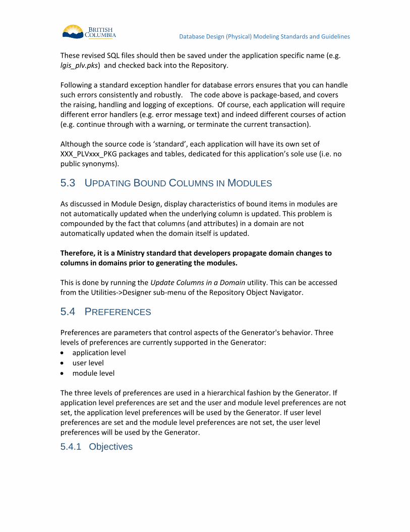
Database Design (Physical) Modeling Standards and Guidelines
These revised SQL files should then be saved under the application specific name (e.g. lgis_plv.pks) and checked back into the Repository. Following a standard exception handler for database errors ensures that you can handle such errors consistently and robustly. The code above is package-based, and covers the raising, handling and logging of exceptions. Of course, each application will require different error handlers (e.g. error message text) and indeed different courses of action (e.g. continue through with a warning, or terminate the current transaction). Although the source code is ‘standard’, each application will have its own set of XXX_PLVxxx_PKG packages and tables, dedicated for this application’s sole use (i.e. no public synonyms).
5.3 UPDATING BOUND COLUMNS IN MODULES As discussed in Module Design, display characteristics of bound items in modules are not automatically updated when the underlying column is updated. This problem is compounded by the fact that columns (and attributes) in a domain are not automatically updated when the domain itself is updated. Therefore, it is a Ministry standard that developers propagate domain changes to columns in domains prior to generating the modules. This is done by running the Update Columns in a Domain utility. This can be accessed from the Utilities->Designer sub-menu of the Repository Object Navigator.
5.4 PREFERENCES Preferences are parameters that control aspects of the Generator's behavior. Three levels of preferences are currently supported in the Generator:
application level
user level
module level The three levels of preferences are used in a hierarchical fashion by the Generator. If application level preferences are set and the user and module level preferences are not set, the application level preferences will be used by the Generator. If user level preferences are set and the module level preferences are not set, the user level preferences will be used by the Generator.
Objectives 5.4.1
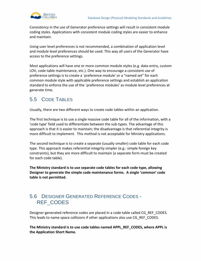
Database Design (Physical) Modeling Standards and Guidelines
Consistency in the use of Generator preference settings will result in consistent module coding styles. Applications with consistent module coding styles are easier to enhance and maintain. Using user level preferences is not recommended, a combination of application level and module level preferences should be used. This way all users of the Generator have access to the preference settings. Most applications will have one or more common module styles (e.g. data-entry, custom LOV, code table maintenance, etc.). One way to encourage a consistent use of preference settings is to create a `preference module' or a "named set" for each common module style with applicable preference settings and establish an application standard to enforce the use of the `preference modules' as module level preferences at generate time.
5.5 CODE TABLES Usually, there are two different ways to create code tables within an application. The first technique is to use a single massive code table for all of the information, with a 'code type' field used to differentiate between the sub-types. The advantage of this approach is that it is easier to maintain; the disadvantage is that referential integrity is more difficult to implement. This method is not acceptable for Ministry applications. The second technique is to create a separate (usually smaller) code table for each code type. This approach makes referential integrity simpler (e.g.: simple foreign key constraints), but they are more difficult to maintain (a separate form must be created for each code table). The Ministry standard is to use separate code tables for each code type, allowing Designer to generate the simple code maintenance forms. A single ‘common’ code table is not permitted.
5.6 DESIGNER GENERATED REFERENCE CODES - REF_CODES
Designer-generated reference codes are placed in a code table called CG_REF_CODES. This leads to name space collisions if other applications also use CG_REF_CODES. The Ministry standard is to use code tables named APPL_REF_CODES, where APPL is the Application Short Name.
Database Design (Physical) Modeling Standards and Guidelines
This is controlled via an option. In Design Editor, select Options -> Generator Options -> General.
Figure 9: Generator Options
Select 'Container Wide Table' for Scope of Reference Code Table (repeat this step for each developer workstation).
Figure 10: Reference Code Table Scope
It is the Ministry standard to reverse-engineer this <APPL_REF>_CODES table back into the repository application, for documentation purposes. Delivery of this table may be via an export, or via the DDL creation script and data load SQL script.
Database Design (Physical) Modeling Standards and Guidelines
6 MAINTENANCE PHASE
6.1 OVERALL GUIDELINES This section presents some overall guidelines to assist in keeping the Repository application current during the maintenance phase.
Synchronizing Table Definitions 6.1.1 Changes to tables must be initiated from within Designer, ideally from the logical model, or from the server model table definition). It is not permissible to directly update the table definition in the database in any ministry applications. All changes must be pushed from the Designer SCM repository to the target environment It is a Ministry standard that all table definitions be forward_engineered from the Designer 10g SCM repository, and that the associated entity be first updated prior to transforming the changes to the server model. There are exceptions to this such as journal tables, which must be reverse-engineered and retrofitted to their appropriate entity. For clarification please contact the ministry SCM Administrator. See Capture Design of Server Model for more information on synchronizing the table definition in the repository with its definition in the production database.
Synchronizing View Definitions 6.1.2 Changes to views must be initiated from within Designer (from the view definition). It is not permissible to directly update the view definition in the database in any ministry environment. All changes must be pushed from the Designer SCM repository to the target environment. It is a Ministry standard that all view definitions be forward engineered from the Designer 10g SCM repository, and that the associated view metadata in the server model be first updated prior to the pushing the changes to the server model See Capture Design of Server Model for more information on synchronizing the view definition in the repository with its definition in the production database The process of capturing view definitions is the same as capturing a table definition.
Synchronizing Domain Definitions 6.1.3 If the allowable values in a domain change, then these changes should be applied to the domain definitions in the repository. Once confirmed, these changes must be propagated to the attributes and columns using the domain.
Database Design (Physical) Modeling Standards and Guidelines
This is performed via the Update Columns/Attributes in a Domain, found under the Utilities menu item of the Design Editor. Once the columns are updated, then the affected tables should be re-generated using the Generate Database from Server Model utility. If the existing application was generated using Designer Version 1.3.2 or previous, then you'll need to: 1. Find the name of the in-line check constraint (e.g. SYS_C00xxxx) in the
USER_CONSTRAINTS or ALL_CONSTRAINTS view
2. Drop the obsolete check constraint(s)
3. Manually write the 'alter table' statements, or
Run Generate Database from Server Model with a connection to the production database, which will reconcile the differences and create a DDL file with the 'alter table' statements
If the application was generated using Designer 2.1.2, 6.0 or above, then the domains will have been enforced using named checked constraints (e.g. AVCON_xxxxx_). Designer's Generate Database from Server Model will do the above steps for you, as the following screen shot illustrates:
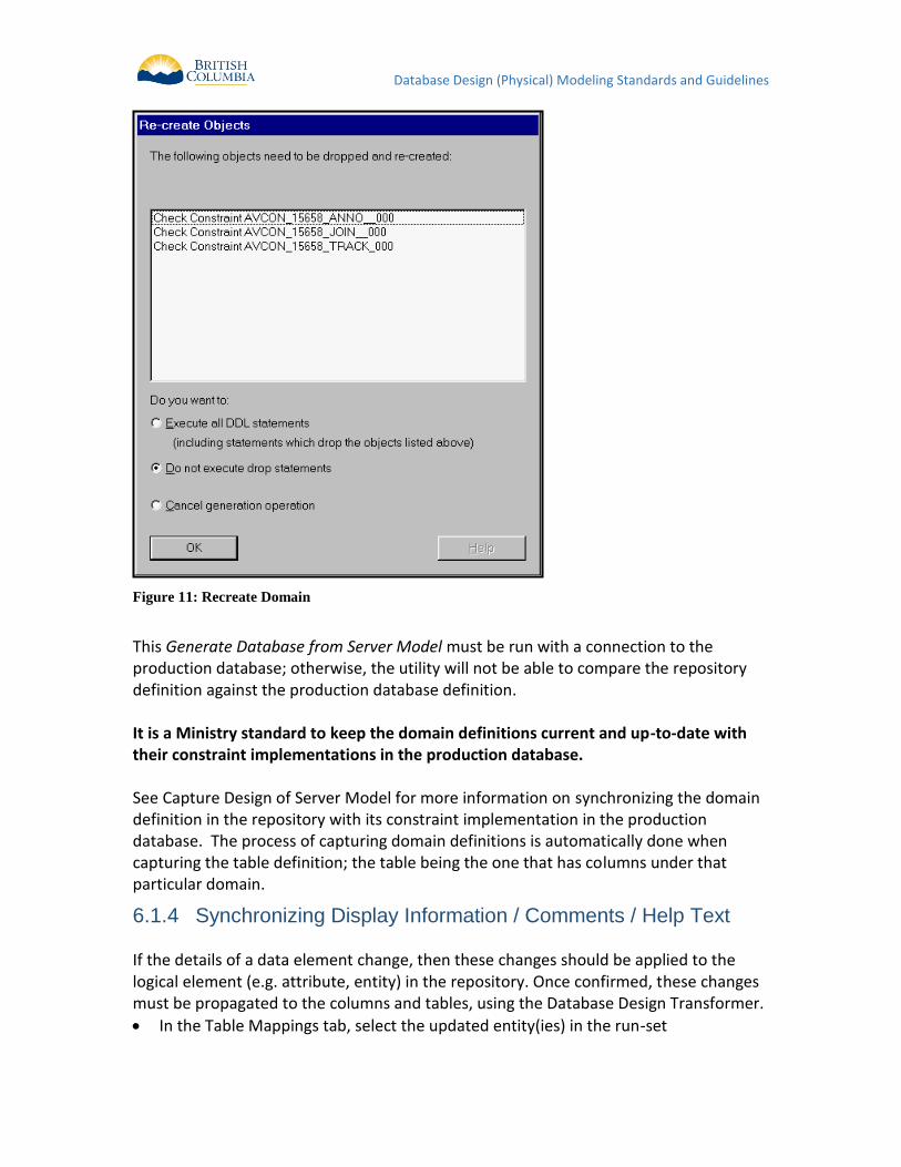
Database Design (Physical) Modeling Standards and Guidelines
Figure 11: Recreate Domain
This Generate Database from Server Model must be run with a connection to the production database; otherwise, the utility will not be able to compare the repository definition against the production database definition. It is a Ministry standard to keep the domain definitions current and up-to-date with their constraint implementations in the production database. See Capture Design of Server Model for more information on synchronizing the domain definition in the repository with its constraint implementation in the production database. The process of capturing domain definitions is automatically done when capturing the table definition; the table being the one that has columns under that particular domain.
Synchronizing Display Information / Comments / Help Text 6.1.4 If the details of a data element change, then these changes should be applied to the logical element (e.g. attribute, entity) in the repository. Once confirmed, these changes must be propagated to the columns and tables, using the Database Design Transformer.
In the Table Mappings tab, select the updated entity(ies) in the run-set
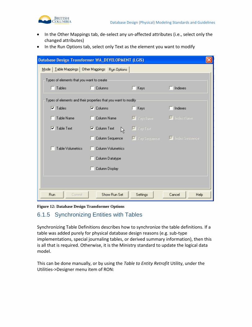
Database Design (Physical) Modeling Standards and Guidelines
In the Other Mappings tab, de-select any un-affected attributes (i.e., select only the changed attributes)
In the Run Options tab, select only Text as the element you want to modify
Figure 12: Database Design Transformer Options
Synchronizing Entities with Tables 6.1.5 Synchronizing Table Definitions describes how to synchronize the table definitions. If a table was added purely for physical database design reasons (e.g. sub-type implementations, special journaling tables, or derived summary information), then this is all that is required. Otherwise, it is the Ministry standard to update the logical data model. This can be done manually, or by using the Table to Entity Retrofit Utility, under the Utilities->Designer menu item of RON:

Database Design (Physical) Modeling Standards and Guidelines
Figure 13: Entity Retrofit
Note: This Retrofit will only process new tables, and not update an existing entity.
Synchronizing Module Definitions 6.1.6
7 DESIGNER GENERATION
7.1 GENERATE DATABASE FROM SERVER MODEL The Generate Database from Server Model is a repository utility that produces SQL scripts that can be used to create database objects. The Server Generator is used after the developer has finished the physical database design, and produces DDL command files to build a "live" database. The Server Generator creates a number of scripts with file extensions with the following conventions:
Database Objects Generated Oracle Scripts
ALLOWABLE VALUES <File_Prefix>.avt
CODE CONTROL SEQUENCES <File_Prefix>.ccs
CLUSTER <File_Prefix>.cls
CLUSTER INDEXES <File_Prefix>.cli
CONSTRAINTS <File_Prefix>.con
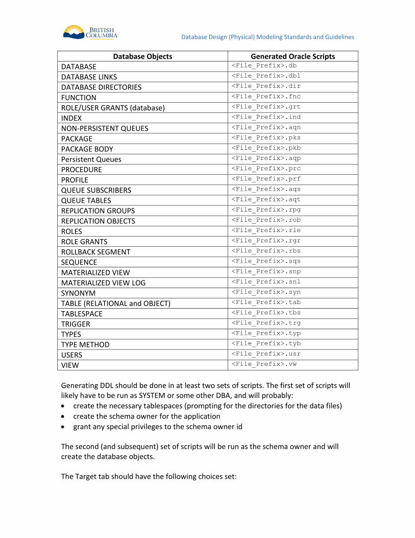
Database Design (Physical) Modeling Standards and Guidelines
Database Objects Generated Oracle Scripts
DATABASE <File_Prefix>.db
DATABASE LINKS <File_Prefix>.dbl
DATABASE DIRECTORIES <File_Prefix>.dir
FUNCTION <File_Prefix>.fnc
ROLE/USER GRANTS (database) <File_Prefix>.grt
INDEX <File_Prefix>.ind
NON-PERSISTENT QUEUES <File_Prefix>.aqn
PACKAGE <File_Prefix>.pks
PACKAGE BODY <File_Prefix>.pkb
Persistent Queues <File_Prefix>.aqp
PROCEDURE <File_Prefix>.prc
PROFILE <File_Prefix>.prf
QUEUE SUBSCRIBERS <File_Prefix>.aqs
QUEUE TABLES <File_Prefix>.aqt
REPLICATION GROUPS <File_Prefix>.rpg
REPLICATION OBJECTS <File_Prefix>.rob
ROLES <File_Prefix>.rle
ROLE GRANTS <File_Prefix>.rgr
ROLLBACK SEGMENT <File_Prefix>.rbs
SEQUENCE <File_Prefix>.sqs
MATERIALIZED VIEW <File_Prefix>.snp
MATERIALIZED VIEW LOG <File_Prefix>.snl
SYNONYM <File_Prefix>.syn
TABLE (RELATIONAL and OBJECT) <File_Prefix>.tab
TABLESPACE <File_Prefix>.tbs
TRIGGER <File_Prefix>.trg
TYPES <File_Prefix>.typ
TYPE METHOD <File_Prefix>.tyb
USERS <File_Prefix>.usr
VIEW <File_Prefix>.vw
Generating DDL should be done in at least two sets of scripts. The first set of scripts will likely have to be run as SYSTEM or some other DBA, and will probably:
create the necessary tablespaces (prompting for the directories for the data files)
create the schema owner for the application
grant any special privileges to the schema owner id The second (and subsequent) set of scripts will be run as the schema owner and will create the database objects. The Target tab should have the following choices set:
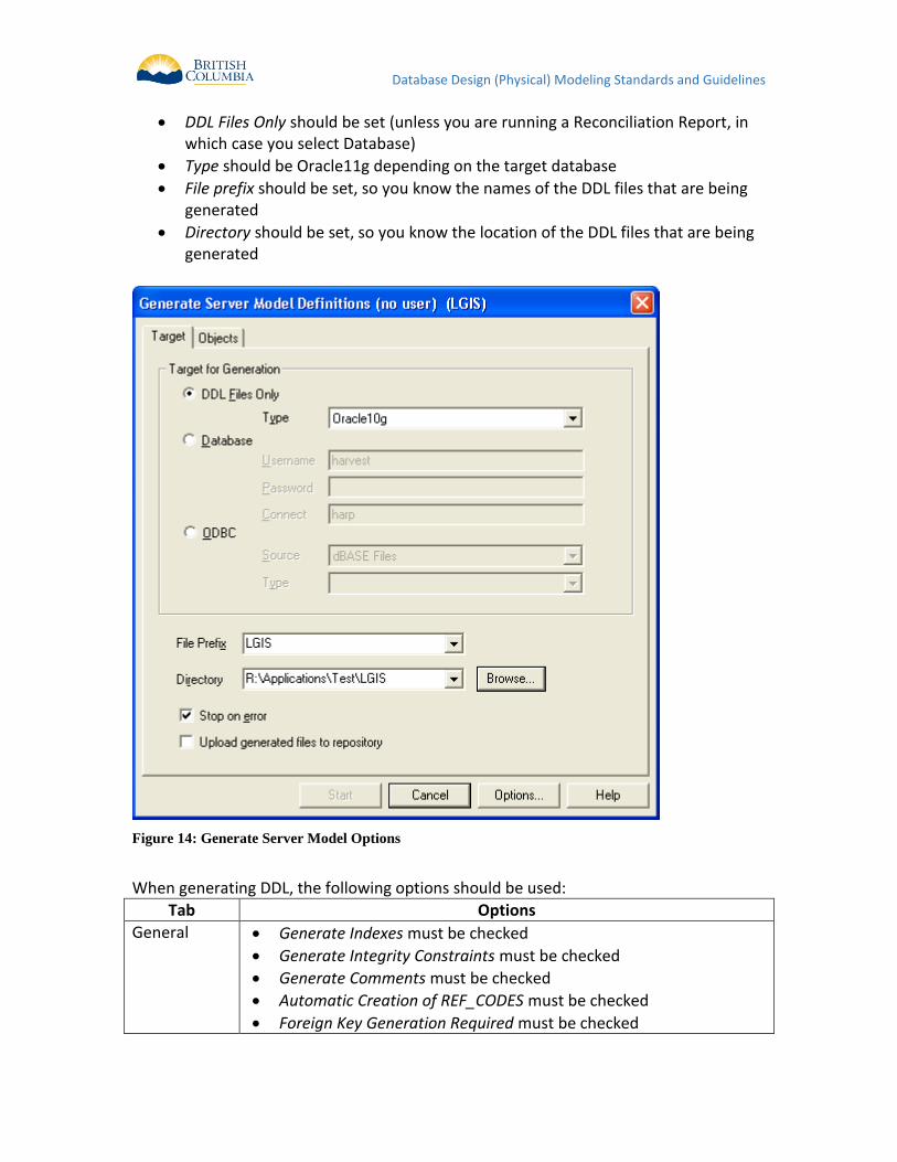
Database Design (Physical) Modeling Standards and Guidelines
DDL Files Only should be set (unless you are running a Reconciliation Report, in which case you select Database)
Type should be Oracle11g depending on the target database
File prefix should be set, so you know the names of the DDL files that are being generated
Directory should be set, so you know the location of the DDL files that are being generated
Figure 14: Generate Server Model Options
When generating DDL, the following options should be used:
Tab Options
General Generate Indexes must be checked
Generate Integrity Constraints must be checked
Generate Comments must be checked
Automatic Creation of REF_CODES must be checked
Foreign Key Generation Required must be checked
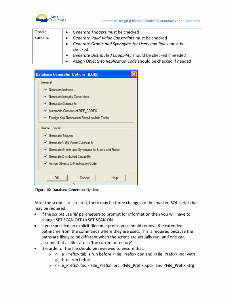
Database Design (Physical) Modeling Standards and Guidelines
Oracle Specific
Generate Triggers must be checked
Generate Valid Value Constraints must be checked
Generate Grants and Synonyms for Users and Roles must be checked
Generate Distributed Capability should be checked if needed
Assign Objects to Replication Code should be checked if needed
Figure 15: Database Generator Options
After the scripts are created, there may be three changes to the 'master' SQL script that may be required:
if the scripts use '&' parameters to prompt for information then you will have to change SET SCAN OFF to SET SCAN ON
if you specified an explicit filename prefix, you should remove the extended pathname from the commands where they are used. This is required because the paths are likely to be different when the scripts are actually run, and one can assume that all files are in 'the current directory'
the order of the file should be reviewed to ensure that: o <File_Prefix>.tab is run before <File_Prefix>.con and <File_Prefix>.ind; with
all three run before o <File_Prefix>.fnc, <File_Prefix>.prc, <File_Prefix>.pck, and <File_Prefix>.trg
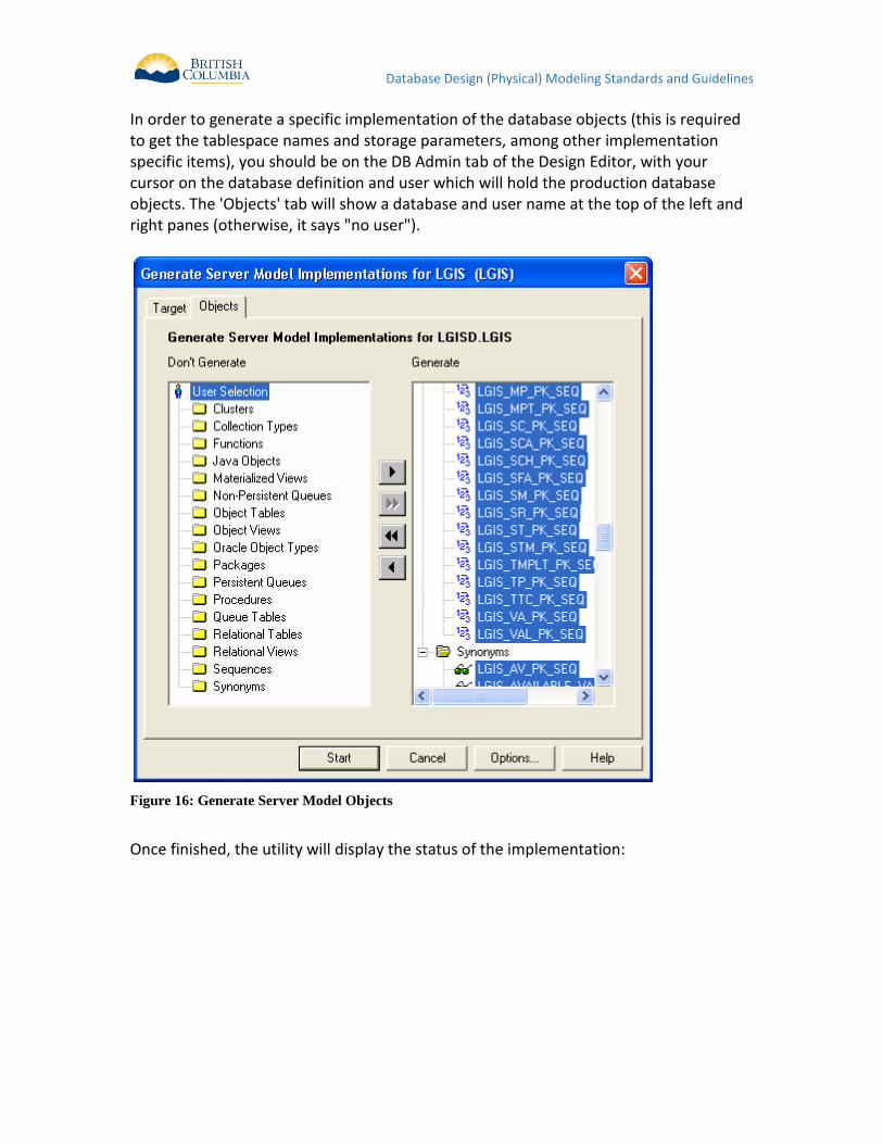
Database Design (Physical) Modeling Standards and Guidelines
In order to generate a specific implementation of the database objects (this is required to get the tablespace names and storage parameters, among other implementation specific items), you should be on the DB Admin tab of the Design Editor, with your cursor on the database definition and user which will hold the production database objects. The 'Objects' tab will show a database and user name at the top of the left and right panes (otherwise, it says "no user").
Figure 16: Generate Server Model Objects
Once finished, the utility will display the status of the implementation:
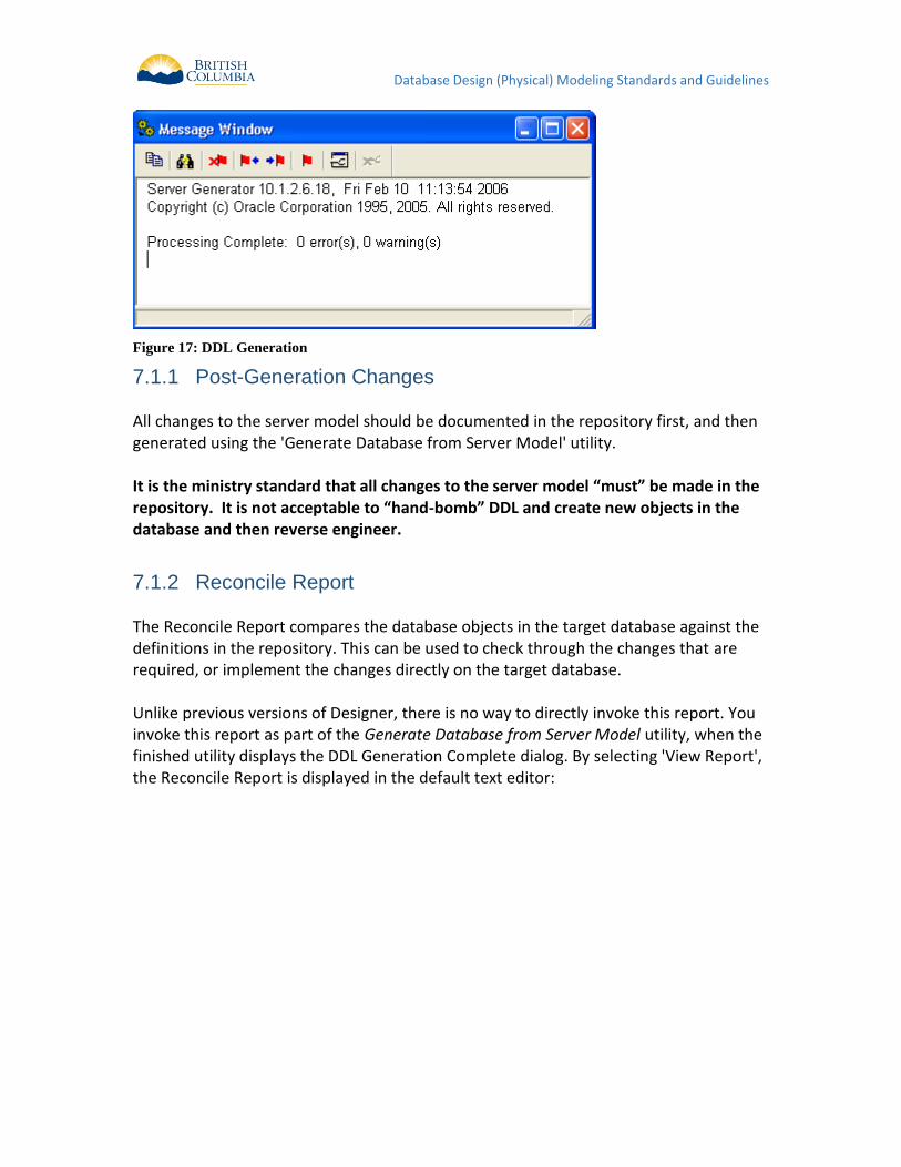
Database Design (Physical) Modeling Standards and Guidelines
Figure 17: DDL Generation
Post-Generation Changes 7.1.1 All changes to the server model should be documented in the repository first, and then generated using the 'Generate Database from Server Model' utility. It is the ministry standard that all changes to the server model “must” be made in the repository. It is not acceptable to “hand-bomb” DDL and create new objects in the database and then reverse engineer.
Reconcile Report 7.1.2 The Reconcile Report compares the database objects in the target database against the definitions in the repository. This can be used to check through the changes that are required, or implement the changes directly on the target database. Unlike previous versions of Designer, there is no way to directly invoke this report. You invoke this report as part of the Generate Database from Server Model utility, when the finished utility displays the DDL Generation Complete dialog. By selecting 'View Report', the Reconcile Report is displayed in the default text editor:
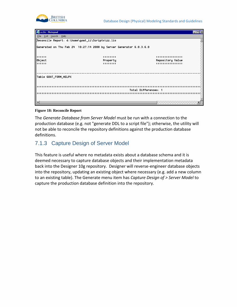
Database Design (Physical) Modeling Standards and Guidelines
Figure 18: Reconcile Report
The Generate Database from Server Model must be run with a connection to the production database (e.g. not "generate DDL to a script file"); otherwise, the utility will not be able to reconcile the repository definitions against the production database definitions.
Capture Design of Server Model 7.1.3 This feature is useful where no metadata exists about a database schema and it is deemed necessary to capture database objects and their implementation metadata back into the Designer 10g repository. Designer will reverse-engineer database objects into the repository, updating an existing object where necessary (e.g. add a new column to an existing table). The Generate menu item has Capture Design of > Server Model to capture the production database definition into the repository.
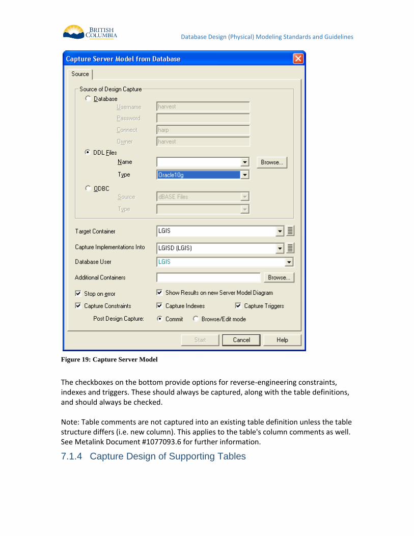
Database Design (Physical) Modeling Standards and Guidelines
Figure 19: Capture Server Model
The checkboxes on the bottom provide options for reverse-engineering constraints, indexes and triggers. These should always be captured, along with the table definitions, and should always be checked. Note: Table comments are not captured into an existing table definition unless the table structure differs (i.e. new column). This applies to the table's column comments as well. See Metalink Document #1077093.6 for further information.
Capture Design of Supporting Tables 7.1.4
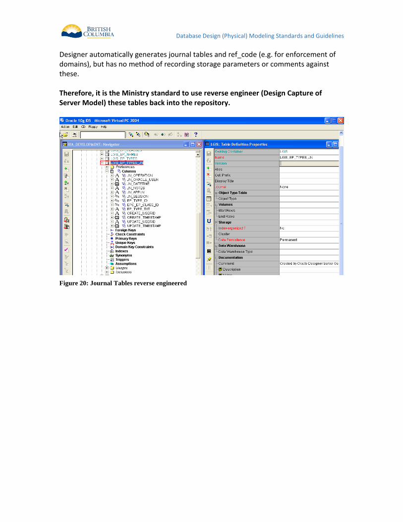
Database Design (Physical) Modeling Standards and Guidelines
Designer automatically generates journal tables and ref_code (e.g. for enforcement of domains), but has no method of recording storage parameters or comments against these. Therefore, it is the Ministry standard to use reverse engineer (Design Capture of Server Model) these tables back into the repository.
Figure 20: Journal Tables reverse engineered
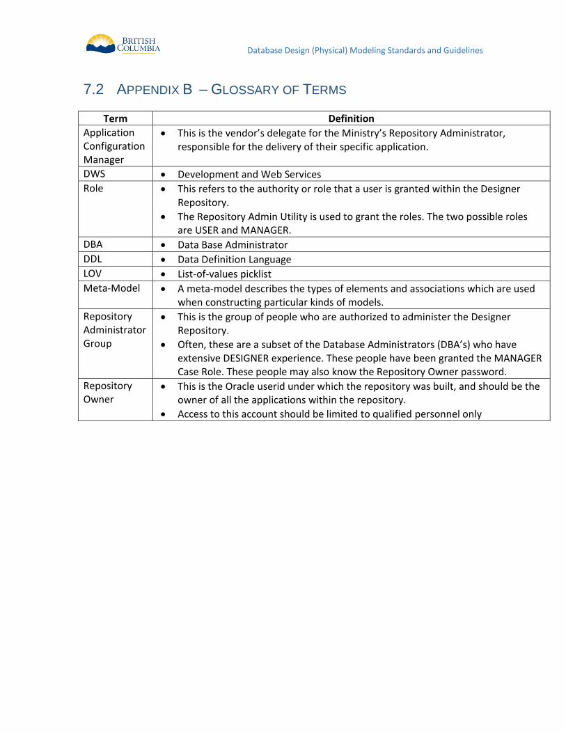
Database Design (Physical) Modeling Standards and Guidelines
7.2 APPENDIX B – GLOSSARY OF TERMS
Term Definition
Application Configuration Manager
This is the vendor’s delegate for the Ministry’s Repository Administrator, responsible for the delivery of their specific application.
DWS Development and Web Services
Role This refers to the authority or role that a user is granted within the Designer Repository.
The Repository Admin Utility is used to grant the roles. The two possible roles are USER and MANAGER.
DBA Data Base Administrator
DDL Data Definition Language
LOV List-of-values picklist
Meta-Model A meta-model describes the types of elements and associations which are used when constructing particular kinds of models.
Repository Administrator Group
This is the group of people who are authorized to administer the Designer Repository.
Often, these are a subset of the Database Administrators (DBA’s) who have extensive DESIGNER experience. These people have been granted the MANAGER Case Role. These people may also know the Repository Owner password.
Repository Owner
This is the Oracle userid under which the repository was built, and should be the owner of all the applications within the repository.
Access to this account should be limited to qualified personnel only
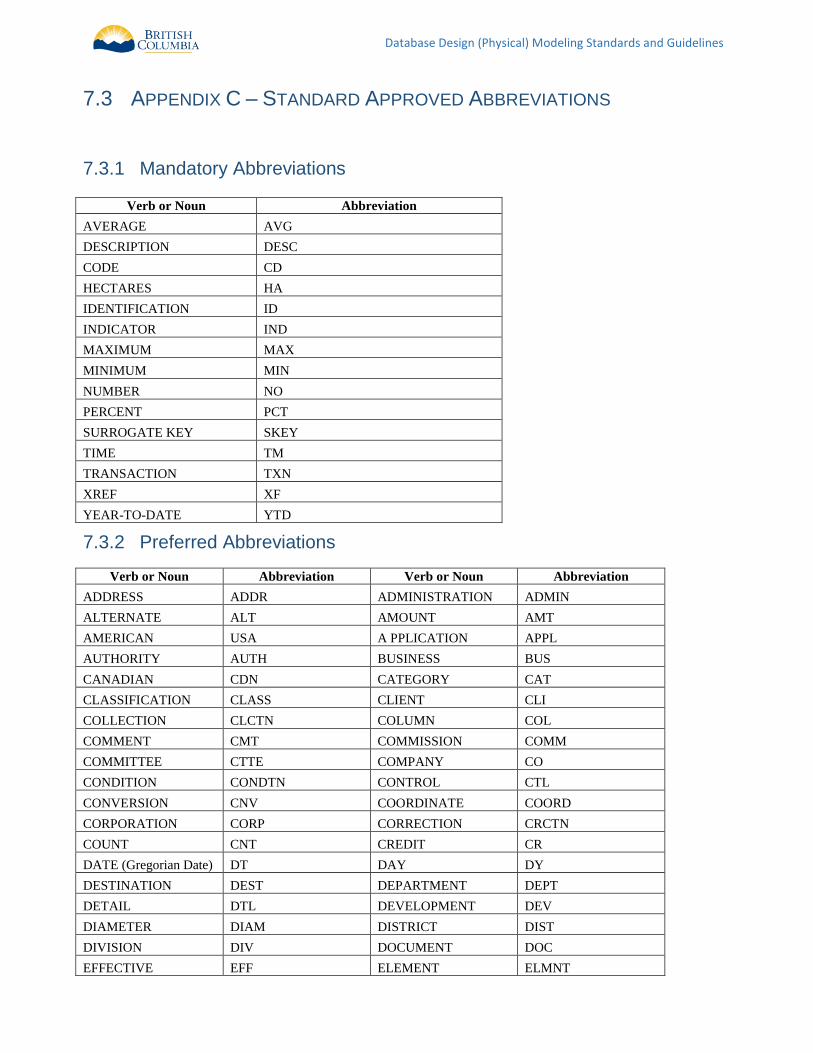
Database Design (Physical) Modeling Standards and Guidelines
7.3 APPENDIX C – STANDARD APPROVED ABBREVIATIONS
Mandatory Abbreviations 7.3.1
Verb or Noun Abbreviation
AVERAGE AVG
DESCRIPTION DESC
CODE CD
HECTARES HA
IDENTIFICATION ID
INDICATOR IND
MAXIMUM MAX
MINIMUM MIN
NUMBER NO
PERCENT PCT
SURROGATE KEY SKEY
TIME TM
TRANSACTION TXN
XREF XF
YEAR-TO-DATE YTD
Preferred Abbreviations 7.3.2
Verb or Noun Abbreviation Verb or Noun Abbreviation
ADDRESS ADDR ADMINISTRATION ADMIN
ALTERNATE ALT AMOUNT AMT
AMERICAN USA A PPLICATION APPL
AUTHORITY AUTH BUSINESS BUS
CANADIAN CDN CATEGORY CAT
CLASSIFICATION CLASS CLIENT CLI
COLLECTION CLCTN COLUMN COL
COMMENT CMT COMMISSION COMM
COMMITTEE CTTE COMPANY CO
CONDITION CONDTN CONTROL CTL
CONVERSION CNV COORDINATE COORD
CORPORATION CORP CORRECTION CRCTN
COUNT CNT CREDIT CR
DATE (Gregorian Date) DT DAY DY
DESTINATION DEST DEPARTMENT DEPT
DETAIL DTL DEVELOPMENT DEV
DIAMETER DIAM DISTRICT DIST
DIVISION DIV DOCUMENT DOC
EFFECTIVE EFF ELEMENT ELMNT
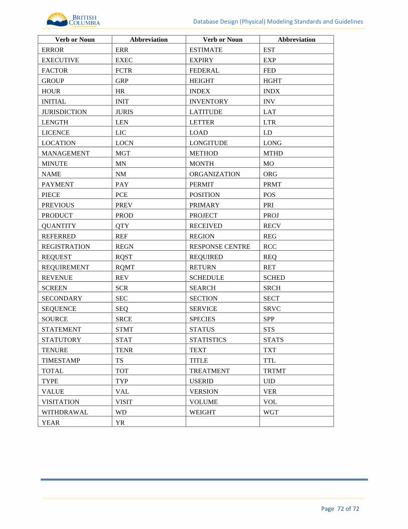
Database Design (Physical) Modeling Standards and Guidelines
72 of 72 Page
Verb or Noun Abbreviation Verb or Noun Abbreviation
ERROR ERR ESTIMATE EST
EXECUTIVE EXEC EXPIRY EXP
FACTOR FCTR FEDERAL FED
GROUP GRP HEIGHT HGHT
HOUR HR INDEX INDX
INITIAL INIT INVENTORY INV
JURISDICTION JURIS LATITUDE LAT
LENGTH LEN LETTER LTR
LICENCE LIC LOAD LD
LOCATION LOCN LONGITUDE LONG
MANAGEMENT MGT METHOD MTHD
MINUTE MN MONTH MO
NAME NM ORGANIZATION ORG
PAYMENT PAY PERMIT PRMT
PIECE PCE POSITION POS
PREVIOUS PREV PRIMARY PRI
PRODUCT PROD PROJECT PROJ
QUANTITY QTY RECEIVED RECV
REFERRED REF REGION REG
REGISTRATION REGN RESPONSE CENTRE RCC
REQUEST RQST REQUIRED REQ
REQUIREMENT RQMT RETURN RET
REVENUE REV SCHEDULE SCHED
SCREEN SCR SEARCH SRCH
SECONDARY SEC SECTION SECT
SEQUENCE SEQ SERVICE SRVC
SOURCE SRCE SPECIES SPP
STATEMENT STMT STATUS STS
STATUTORY STAT STATISTICS STATS
TENURE TENR TEXT TXT
TIMESTAMP TS TITLE TTL
TOTAL TOT TREATMENT TRTMT
TYPE TYP USERID UID
VALUE VAL VERSION VER
VISITATION VISIT VOLUME VOL
WITHDRAWAL WD WEIGHT WGT
YEAR YR