dataduino - arduino data acquisition unit · pdf filedataduino - arduino data acquisition unit...
TRANSCRIPT

DataDuino - Arduino Data Acquisition Unit
Date: 31/10/12 Version: 1.0 By: Matt Little
The DataDuino is an Arduino data acquisition unit which stores data to an SD card (as a .csv file). It uses a real time clock with a back-up battery for accurate data logging and time-stamping.It can record 5 digital channels and 4 analogue channels. It can easily be configured to read 1-wire temperature sensors.It can also be used with Arduino shields.It utilises an Arduino UNO brain.The data logger sample period and some parameters can be changed using serial commands.It runs on 4.5 to 5.5V supply, such as a re-purposed phone charger.Note: This requires an FTDI USB to serial 3V3 cable for programming.Note: an SD card is NOT included.
Parts included:
16MHz crystal
32.768kHz
crystal
3v3 voltage
regulator
8 pin IC holder
PCF6593 Atmega 328 with UNO
boot-loader
Capacitor
PCB 28 pin IC holder
CR2032 Battery
Battery Holder
LEDs
SD Card Holder
Power Jack
Switch Diodes Resistors

Parts list:
Reference Description Reference Description
BT1 Battery holder R1 1k
CR2032 3V BATT R2 10k
C1 100uF R3 10k
C2 100nF R4 10k
C3 10uF R5 1k (not used/supplied)
C4 22pF R6 2k2
C5 22pF R7 2k2
C6 10uF R8 2k2
C7 10uF R9 3k3
C8 Trimmer capacitor 8-30pF R10 3k3
C9 100nf R11 3k3
D1 LED power (3mm green) R12 100k
D2 1N4148 R13 4k7 (not used/supplied)
D3 1N4148 R14 1k
D4 LED RTC (Not used/ supplied) R15 10k
D5 LED data (3mm red) SW1 SPST
IC1 ATMEGA328P-P – UNO boot-loader U1 PCF8563
28 pin DIL socket 8 pin DIL socket
J1 CON-SD-MMC-3 U2 MC1703 (3v3 regulator)
P1 2.1mm DC power socket X1 32.27 kHz
P2 3 x 2 ISP connector (not supplied) X2 16MHz
P3 6 pin Programming header PCB
P4 Not used/supplied
You will also need (not supplied):• a computer with the Arduino IDE installed • a FTDI USB to serial cable with code: TTL-232R-3V3, such as this:
Available here (among other places): http://www.ftdichip.com/Products/Cables/USBTTLSerial.htm

Tools required:
Soldering Iron
Solder
Side cutters Small nosed pliers
Instructions:
Step: 1 Place the SD card holder
There are two locating holes which hold the SD card holder to the PCB.The PCB footprint is slightly off for two of the pins (shown near the screwdriver head). Slightly bend the SD card holder pins so that they sit onto the PCB pads.
Step: 2 Solder the SD card holder
The SD card holder is the only surface mount component. It requires very careful soldering. Firstly solder the large grounding pads on each side of the component.Ensure that the solder does not short any pads.

Step: 3 Solder the resistors
Identify all the resistors. You will have:Quantity Value Part Reference
1 100k R12
2 1k R1, R14
3 3k3 R9, R10, R11
3 2k2 R6, R7, R8
4 10k R2, R3, R4, R15
Resistors R5 and R13 are NOT required or included.Use the identify chart at the end of these instructions or a multimeter.Solder into the relevant places.Their orientation does not matter.
Step: 4 Solder the diodes
Two 1N4148 diodes are included. They must be inserted in the correct direction (please check the photo here). The black line on the diode is aligned with the thick white line on the PCB.
Step: 5 Solder the IC sockets
Check the orientation. The notch on the IC socket should align with the white notch drawn on the PCB.
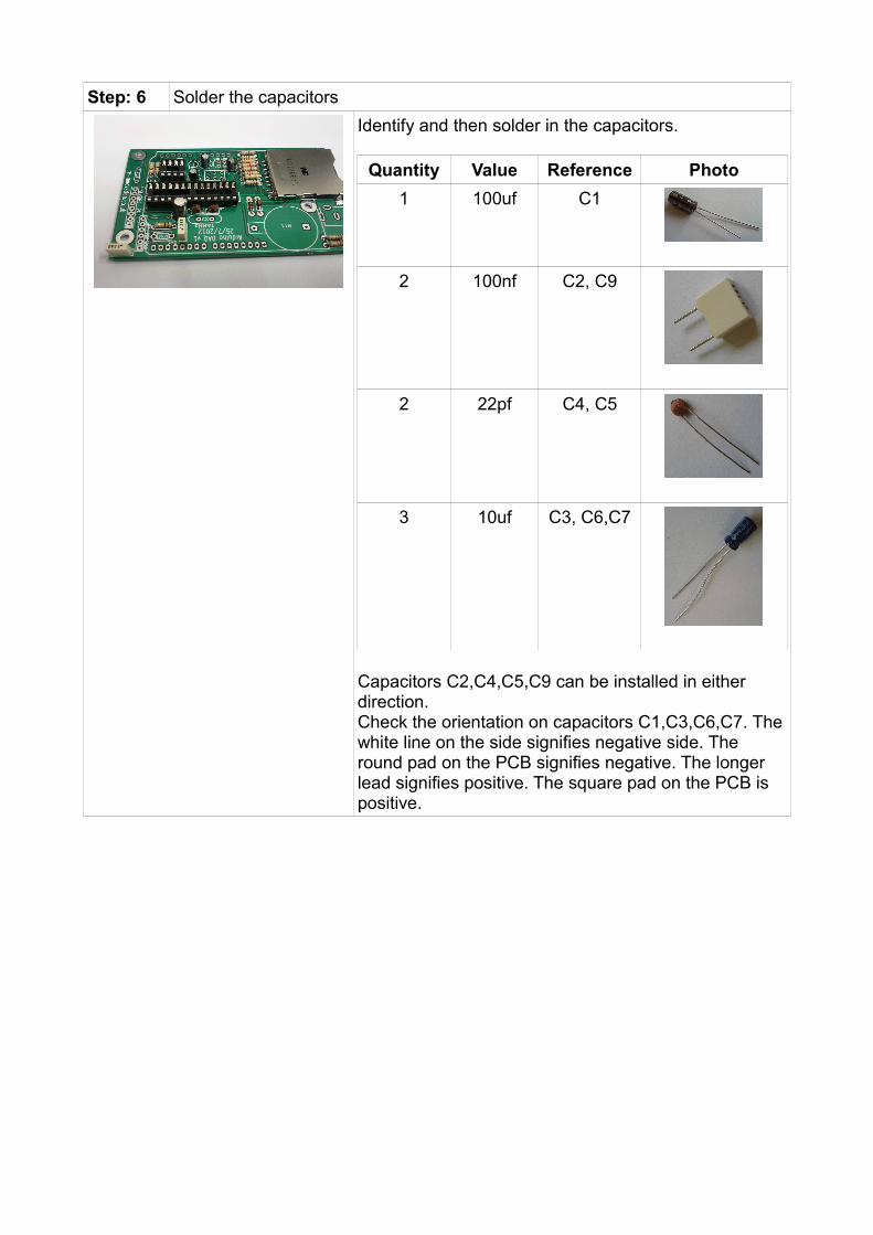
Step: 6 Solder the capacitors
Identify and then solder in the capacitors.
Quantity Value Reference Photo
1 100uf C1
2 100nf C2, C9
2 22pf C4, C5
3 10uf C3, C6,C7
Capacitors C2,C4,C5,C9 can be installed in either direction.Check the orientation on capacitors C1,C3,C6,C7. The white line on the side signifies negative side. The round pad on the PCB signifies negative. The longer lead signifies positive. The square pad on the PCB is positive.

Step: 7 Solder battery holder, DC plug and reset switch
Solder these components.
Step: 8 Solder trimmer capacitor
Solder in the trimmer capacitor. Follow the white diagram on the PCB for orientation.
Step: 9 Solder LEDs
Both LEDs are 3mm types. Use green to signify power (D1) and red to signify data (D5).You can also bend them at 90 degrees if used in an enclosure.Double check their orientation. The long lead is positive. The flat side of the LED body is negative – ensure this matches the PCB white diagram. (Note: On this batch of PCB s the solder mask on the underside of the circuit board is not correct and almost covers the solder pad. The leads will still solder correctly or you

can solder from the top side of the PCB).
Step: 10 Solder crystals
Two timing crystals are used. One is a tiny watch crystal used for the real time clock. It has a 32.768 kHz frequency.It is quite fragile so solder carefully. It can be mounted in either orientation.The other, larger crystal is 16MHz and used as the clock frequency for the Atmega 328 micro-controller.Again – its orientation does not matter.
Step: 11 Solder programming header pins
A 6 way header pin is used to program and interface to the micro-controller. This is soldered into port P3 PROGRAM.

Step: 12 Solder 3V3 regulator
A 3v3 regulator (part number MC1703) is used to supply power for the SD card.It is a 3-pin device. Ensure the flat side of the component matches the flat side of the white diagram on the PCB.
Step: 13 Insert ICs
Now we can insert the two integrated circuits (ICs). Be very careful when pushing in these ICs or you might bend the legs too much.Firstly insert the real time clock (marked PCF8563) into the 8 pin socket. Ensure correct orientation, so the notches on the IC match the notch on the IC socket and the PCB.Secondly insert the 28 pin IC marked ATMEGA328P-P. This has the Arduino UNO bootloader installed. Again ensure correct orientation, with the notch pointing towards the 're-innovation.co.uk' text.
Step: 14 Insert real time clock backup battery
Lastly for the construction of the device, insert the backup battery. This is inserted with the positive terminal facing upwards. This battery powers the real time clock when there is no power to the board. It should last over 2 years before requiring a change.
Step: 15 Build is finished!
Have a nice cup of tea.

Once the device is constructed, the next step is check it powers up OK and then to program the device with the DataDuino code.
Step: 16 Check device powers up
Use a 5V power supply (either a 5V bench top power supply or a 5V output switched mode power supply (as used here)).Apply 5V DC to the 2.1mm DC power jack socket.The inner pin is positive, the outer ring is negative.You should see the green power LED light up. The red data LED might also flash very briefly at power up.
If not: • Test with a multimeter set to DC volts.• Do you have 5V between pins 7 and 8 of the
ATMEGA328P-P?• Do you have 5V between pins 4 and 8 of the
PCF8563?• If not, then re-check your soldering for short
circuits. Also check the ICs are inserted in the correct orientation.

Step: 18 Upload data-logger code from a computer
(Note: These instructions assume the user has some knowledge of the Arduino IDE environment and uploading code – if not please check arduino.cc for numerous examples)
If the unit has powered up OK then you can upload the data logging code.
This requires:• A computer running the Arduino IDE• An FTDI USB to serial lead• The DataDuino code• The DallasTemperature.h files• The Rtc_Pcf8563.h files
1. Check that the FTDI cable works.2. Download the DataDuino code from:
www.re-innovation.co.uk. Save this to your Arduino sketch book.
3. Download the DallasTemperature.h files from:http://milesburton.com/Dallas_Temperature_Control_LibrarySave this to your Arduino sketch book, under libraries.
4. Download the Rtc_Pcf8563.h files from:https://github.com/elpaso/Rtc_Pcf8563Save this to your Arduino sketch book, under libraries.
5. Open the Arduino IDE. This was written for IDE 00.22. It has NOT been tested under version 1.0.
6. Open the DataDuino sketch.7. Ensure that the sketch compiles with no
errors.8. Do NOT use any external power to the
board. Power will be supplied via the FTDI cable.
9. Plug in the FTDI cable to you board. Ensure that the BLACK cable goes at the end towards the IC. The GREEN cable will go towards the edge of the board.
10.Upload code to the arduino. It uses the UNO boot-loader. It should say 'Done Uploading'
11. Once installed open the serial monitor and check information is coming through the serial connection.

Step: 17 Adjust trimmer capacitor (not critical)
Note: This step is only required for more accurate time keeping. Skip this step if you do not have access to a high resolution counter.The PCF8563 can have an accuracy of around +/- 5 mins per year, this is approx a change of 1 second per day.
To test the output of the real time clock we are going to set the CLK_OUT pin to give the crystal frequency (32.768kHz) and then measure it with an accurate counter.
Download the Arduino code 'RTC_clock_adjust' from www.re-innovation.co.uk.Upload the code to the DataDuino. It will then run automatically.Note: During this time there will be no data collected.
Use an accurate frequency counter. If possible one with 8 digit resolution.
Monitor the frequency on pin 7 of the RTC (8-pin IC) and ground.
This frequency should be exactly 32.7680KHz and any inaccuracy will cause the clock to drift.
Use an insulated screwdriver to slowly adjust the trimmer capacitor.
When the frequency is 32.7680kHz then the capacitor is in the correct position.
Re-upload the DataDuino main code (follow step 18 again).

Step: 18 Set Reference
Within the Arduino IDE (in this case version 00.22), open the Serial Monitor (click the highlighted icon).This will open a serial terminal.You will see data scrolling across this terminal at the rate set by the sample time.
First we want to set the reference.
Do this by typing “R??E” into the top line of the terminal, where ?? is the reference number (from 00 to 99).Press SEND.
The device will reset and re-initialise the SD card.
In this example we have changed the reference from 10 to 37.

Step: 19 Set Time
While in the serial terminal we can now set the time on the real time clock.
Enter the time in the format:“T??????E”, where ?????? is the time in the format HHMMSS.
In this example we have changed the time from 15:12:28 to 12:34:00.
Step: 20 Set Date
While in the serial terminal we can now set the date on the real time clock.
Enter the date in the format:“D??????E”, where ?????? is the date in the format DDMMYY.
In this example we have changed the date from 31st October 2012 to 1st February 2011.
Step: 21 Set Sample Time
The last thing we can control via the serial terminal is the sample period.This is set in seconds from 1 to 99999 seconds. This can be adjusted using the command S?????E, where ????? is the sample period in seconds. At the end of this period data will be sampled and stored.In this example the command S00010E has been sent and changed the sample rate from every 5 seconds to every 10 seconds.

Step: 22 Build your interface board – what do YOU want DataDuino to do?
This kit does require you to interface your sensors to it. It is designed as a data - logging back bone for your ideas. You can interface digital signals (such as is a door open or closed), analogue signals (such as voltage), pulse output sensors (such as flow sensors and anemometers) and 1-wire temperature sensors (such as the DS18B20).All digital inputs will need pull up resistors to ensure the readings do not 'float'.Check www.re-innovation.co.uk for some examples of the data logger in action.We would love to hear and see your application and ideas. Please email any photos to [email protected], or leave comments on the DataDuino pages.
Technical information:
Not all of the arduino pins are available for logging. Please see this list for the pin allocations:
Pin Number
Type of data
Allocation
D0 Digital Serial Rx - Can be used if required
D1 Digital Serial Tx - Can be used if required
D2 DigitalClock interrupt at 1 second - Cannot be used
D3 Digital Available
D4 Digital Available
D5 Digital LED indicator - Can be used if required
D6 DigitalSD card - Card detect - Can be used if required
D7 Digital Available
D8 Digital Available
D9 Digital Available
D10 Digital SD card - Chip select - Cannot be used
D11 Digital SD card - MOSI - Cannot be used
D12 Digital SD card - MISO - Cannot be used
D13 Digital SD card - Clock - Cannot be used
A0 Analogue Available
A1 Analogue Available
A2 Analogue Available
A3 Analogue Available
A4 Analogue RTC - SDA - Cannot be used
A5 Analogue RTC - SCL - Cannot be used
Data from pins D3,D4,D7,D8,D9 and A0-3 is recorded in the basic arduino code available.

Arduino code information:
Some example code, including the main DataDuino program is available at www.re-innovation.co.uk.
Overview of the code:
The DataDuino is an Arduino based SD card datalogger.A PCF8563 Real Time Clock is used to timestamp the data.
• Pin D4 is set up to record a DS18B20 1 wire temp sensor (up to 4 sensors can be attached)
• Pin D3 is set up to cound pulses from a sensor (such as a anemometer or flow sensor)
• Pins D7,D8,D9 are set up to record digital information (0 or 1)• Pins A0 to A3 are set up to record analogue information (0 to 1024)
Each logger has a reference (user adjustable from 00-99).Data is written to a .csv file created on an SD card.A new file is created each day. If file alreay present then data is appended.The file name is created from the reference number and the date in the format:RXXDXXXX.csv, where RXX is the reference number and DXXXX is the date in the format DDMM. Data is stored with human readable headers:"Reference, Time, Date, Pulses, Temp1, Temp2, Temp3, Temp4, D7,D8,D9,A0,A1,A2,A3"
As mentioned in the set-up instructions:You can adjust the parameters of the device using serial commands. These parameters are stored in EEPROM.These are:
1. R??EThis will change the reference number to ??
2. T??????EThis will change the time to HHMMSS
3. D??????EThis will change the date to DDMMYY
4. S?????EThis will change the sample period to ????? seconds. Set to 00001 for 1 second data, set to 03600 for 1 hour data. The minimum is 1 second data. The maximum is 99999 seconds
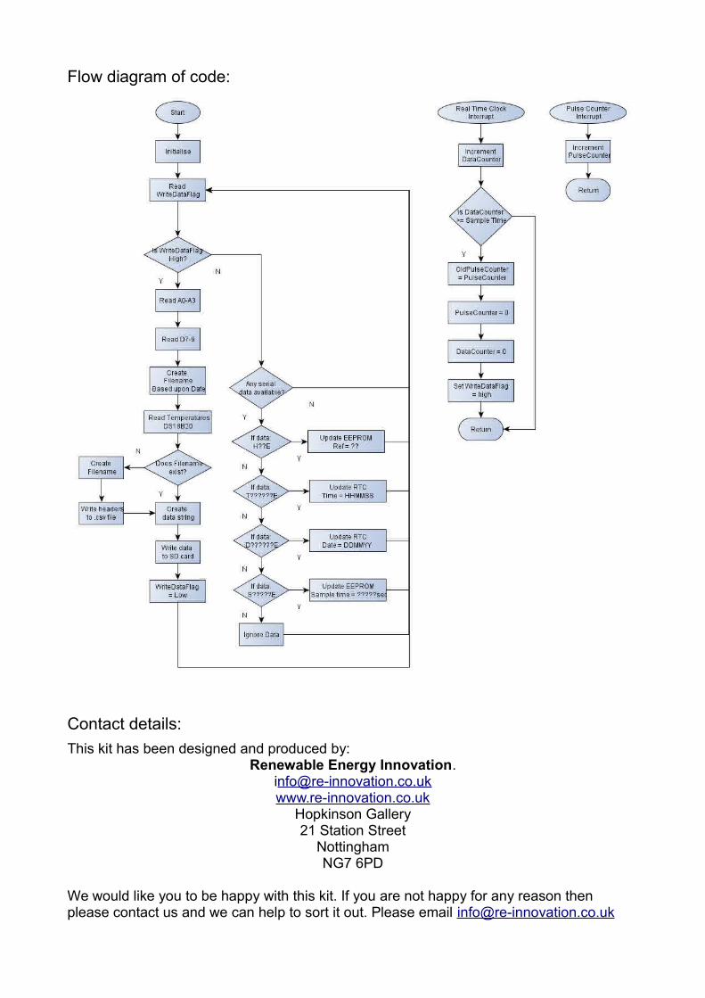
Flow diagram of code:
Contact details:
This kit has been designed and produced by:Renewable Energy Innovation.
Hopkinson Gallery21 Station Street
NottinghamNG7 6PD
We would like you to be happy with this kit. If you are not happy for any reason then please contact us and we can help to sort it out. Please email [email protected]

with any questions or comments.If any parts are missing from your kit then please email [email protected] with details, including where the kit was purchased.
More technical information can be found via www.re-innovation.co.uk.
Useful Information:
Resistor colour codes:

Circuit schematic: