dataflex 16/ ktr-n 49014 en torque measuring shaft ... · dataflex® 16/... torque measuring shaft...
TRANSCRIPT

DATAFLEX® 16/... Torque Measuring Shaft
Operating/Assembly instructions
KTR-N Sheet: Edition:
49014 EN 1 of 19 5
Please observe protection note ISO 16016.
Drawn: 2017-01-02 Sho/Pz Replacing: KTR-N dated 2013-09-02
Verified: 2017-01-02 Pz Replaced by:
DATAFLEX®
Torque measuring shaft type 16/…

DATAFLEX® 16/... Torque Measuring Shaft
Operating/Assembly instructions
KTR-N Sheet: Edition:
49014 EN 2 of 19 5
Please observe protection note ISO 16016.
Drawn: 2017-01-02 Sho/Pz Replacing: KTR-N dated 2013-09-02
Verified: 2017-01-02 Pz Replaced by:
DATAFLEX® is a maintenance-free torque measuring shaft with integrated speed measurement. Com-bined with the steel lamina coupling RADEX®-NC the complete system forms a torsionally stiff, double-cardanic coupling with integrated measuring shaft.
1 Technical data 3
2 Advice 5
2.1 General advice 5 2.2 Safety and advice symbols 5 2.3 General hazard warnings 5 2.4 Intended use 5
3 Storage, transport and packaging 6
3.1 Storage 6 3.2 Transport and packaging 6
4 Assembly 6
4.1 Components of DATAFLEX® torque measuring shaft 6 4.2 Advice for finish bore 7 4.3 Displacements - alignment of the torque measuring shaft 7 4.4 Assembly of the hubs 8 4.5 Assembly of the RADEX®-NC on the DATAFLEX® torque measuring shaft 8 4.6 Advice for assembly of the RADEX®-NC coupling 10 4.7 Advice for assembly of the DATAFLEX® torque measuring shaft 10 4.8 Technical description 10
5 Disposal 18
6 Maintenance and service 18
7 Services, customer service addresses 18
8 EC Certificate of conformity 19
Table of contents

DATAFLEX® 16/... Torque Measuring Shaft
Operating/Assembly instructions
KTR-N Sheet: Edition:
49014 EN 3 of 19 5
Please observe protection note ISO 16016.
Drawn: 2017-01-02 Sho/Pz Replacing: KTR-N dated 2013-09-02
Verified: 2017-01-02 Pz Replaced by:
DATAFLEX® torque measuring shaft
Illustration 1: DATAFLEX® torque measuring shaft
Table 1: Dimensions
DATAFLEX®
type
Dimensions [mm]
d D L1 L2 L3 L4 L5 H B X
16/10
16 52 140 25 90 85 3.5 67 50 12 16/30
16/50
Table 2: Technical data
Coupling size of DATAFLEX® 16/10 16/30 16/50
Electrical data Rated torque TKN [Nm] -10 .. +10 Nm -30 .. +30 Nm -50 .. +50 Nm
Band width of torque signal [kHz] (-3dB) 2
Error in linearity incl. hysteresis [%] 1)
< 0.1
Influence of temperature [%/10K] 0.05
Nominal temperature range [°C] 0 - 55
Supply voltage [V] DC 24 ± 4
Max. current consumption [mA] 100
Torque output Output voltage torque [V] -10 .. +10
Speed output 2)
Number of pulses / revolutions 360
Amplitude [V] 24/5V
DC voltage output [V] 0 - 10
Scale of DC voltage output 16fold via micro switch
Inaccuracy of DC voltage output [%] 3)
± 0.2
Direction signal [V] 24/5V
Mechanical data Static load limit TKmax.
1) [%] 150
Breaking load TK break 1)
[%] 300
Max. bending torque [Nm] 1.07 3.2 5.3
Max. radial force [N] 12 37 61
Max. axial force [kN] 1.1 2.3 3.1
Weight [kg] 0.7
Torsion spring stiffness CT [Nm/rad] 910 2840 4100
Torsion angle with TKN [degrees] 0.63 0.61 0.7
Mass moment of inertia [kgmm2] 22.6
Max. speed [rpm] 10000
1) Referring to rated torque TKN 2) With connection housing DF2 3) Referring to upper range value
1 Technical data

DATAFLEX® 16/... Torque Measuring Shaft
Operating/Assembly instructions
KTR-N Sheet: Edition:
49014 EN 4 of 19 5
Please observe protection note ISO 16016.
Drawn: 2017-01-02 Sho/Pz Replacing: KTR-N dated 2013-09-02
Verified: 2017-01-02 Pz Replaced by:
DATAFLEX® torque measuring shaft in combination with RADEX®-NC
Illustration 2: DATAFLEX® with RADEX
®-NC
Table 3: Dimensions and technical data
Coupling size of DATAFLEX® 16/10 16/30 16/50
Coupling size of RADEX®-NC 20 25
Dimensions [mm]
Dimension d1 / d2 max. 25 35
Dimension D1 59 70
Dimension L6 138 154
Dimension L7 24 32
Dimension L8 146 164
Dimension Ltotal 194 228
Dimension s 4 5
Clamping screw [mm]
Dimension M M6 M8
Tightening torque TA [Nm] 10 25
Mechanical data of combination (DATAFLEX® with RADEX
®-NC)
Mass moment of inertia [kgmm²] 330.6 809
Torsion spring stiffness [Nm/rad] 860 2600 3600
Weight [kg] 1.30 1.75 1.75
Max. speed [rpm] 1)
7500
1) Higher speeds on request; with high speeds please use coupling hubs that are balanced.
1 Technical data

DATAFLEX® 16/... Torque Measuring Shaft
Operating/Assembly instructions
KTR-N Sheet: Edition:
49014 EN 5 of 19 5
Please observe protection note ISO 16016.
Drawn: 2017-01-02 Sho/Pz Replacing: KTR-N dated 2013-09-02
Verified: 2017-01-02 Pz Replaced by:
Please read through these operating/assembly instructions carefully before you start up the measuring shaft. Please pay special attention to the safety instructions! The operating/assembly instructions are part of your product. Please store them carefully and close to the meas-uring shaft. The copyright for these operating/assembly instructions remains with KTR.
Warning of potentially explosive atmospheres
This symbol indicates notes which may contribute to pre-venting bodily injuries or serious bodily injuries that may result in death caused by explosion.
STOP
Warning of personal injury This symbol indicates notes which may contribute to pre-venting bodily injuries or serious bodily injuries that may result in death.
!
Warning of product damages This symbol indicates notes which may contribute to pre-venting material or machine damage.
General advice This symbol indicates notes which may contribute to pre-venting adverse results or conditions.
STOP
With assembly, operation and maintenance of the measuring shaft it has to be made sure that the entire drive train is secured against accidental switch-on. You may be seriously hurt by rotating parts. Please make absolutely sure to read through and observe the following safety indications.
All operations on and with the measuring shaft have to be performed taking into account "safety first".
Please make sure to switch off the power pack before you perform your work on the measuring shaft.
Secure the power pack against accidental switch-on, e. g. by providing warning signs at the place of switch-on or removing the fuse for current supply.
Do not reach into the operation area of the measuring shaft as long as it is in operation.
Secure the rotating components of the measuring shaft against accidental contact. Please provide for the ne-cessary protection devices and covers.
You may only assemble, operate and maintain the measuring shaft if you
have carefully read through the operating/assembly instructions and understood them
had technical training
are authorized by your company
The measuring shaft may only be used in accordance with the technical data (see chapter 1). Unauthorized modi-fications on the measuring shaft are not admissible. We will not assume liability for any damage that may arise. In the interest of further development we reserve the right for technical modifications. The DATAFLEX
® torque measuring shaft described in here corresponds to the technical status at the time of
printing of these operating/assembly instructions.
2 Advice
2.1 General advice
2.2 Safety and advice symbols
2.3 General hazard warnings
2.4 Intended use

DATAFLEX® 16/... Torque Measuring Shaft
Operating/Assembly instructions
KTR-N Sheet: Edition:
49014 EN 6 of 19 5
Please observe protection note ISO 16016.
Drawn: 2017-01-02 Sho/Pz Replacing: KTR-N dated 2013-09-02
Verified: 2017-01-02 Pz Replaced by:
The RADEX
®-N couplings are supplied in preserved condition. Both DATAFLEX
® and RADEX
®-N can be stored
at a dry and covered place for 6 - 9 months.
!
Humid storage rooms are not suitable. Please make sure that condensation is not generated. The best relative air humidity is less than 65 %.
!
In order to avoid any injuries and any kind of damage please always make use of proper transport and lifting equipment.
The couplings are packed differently each depending on size, number and kind of transport. Unless otherwise contractually agreed, packaging will follow the in-house packaging specifications of KTR.
The measuring shaft and the couplings are supplied as single pre-assembled component assemblies. Before assembly the measuring shafts have to be inspected for completeness. The mounting position of DATAFLEX
® is variable. The measurement system can be mounted both horizontally
and vertically.
Components of DATAFLEX
® torque measuring
shaft Components of RADEX
®-NC coupling
Com-ponent
Quantity Component assembly Com-
ponent Quantity Component assembly
1 1 DATAFLEX
® torque measu-
ring shaft 2 2 RADEX
®-NC type EK
Illustration 3: DATAFLEX
® 16 torque measuring shaft with RADEX
®-NC
3 Storage, transport and packaging
3.1 Storage
3.2 Transport and packaging
4 Assembly
4.1 Components of DATAFLEX® torque measuring shaft

DATAFLEX® 16/... Torque Measuring Shaft
Operating/Assembly instructions
KTR-N Sheet: Edition:
49014 EN 7 of 19 5
Please observe protection note ISO 16016.
Drawn: 2017-01-02 Sho/Pz Replacing: KTR-N dated 2013-09-02
Verified: 2017-01-02 Pz Replaced by:
STOP
The maximum permissible bore diameters d1max and d2max (see RADEX
®-NC catalogue) must not be exceeded.
If these figures are disregarded, the coupling may tear. Rotating particles may cause danger to life.
Bores of clamping hubs machined by the customer have to observe concentricity or axial runout, respectively (see illustration 4).
Please make absolutely sure to observe the figures for d1max and d2max.
Carefully align the clamping hubs when the finish bores are drilled.
Illustration 4: Concentricity and axial runout
The displacement figures specified in table 4 provide for sufficient safety to compensate for external influences like, for example, thermal expansion or foundation settling.
!
In order to ensure a long service life of the measuring shaft, the shaft ends have to be accu-rately aligned. Please absolutely observe the displacement figures specified (see table 4). If the figures are exceeded, the measuring shaft with coupling will be damaged.
Please note:
The displacement figures specified in table 4 are maximum figures which must not arise in parallel. If radial, axial and angular displacement arises at the same time, these values must be reduced (see illustration 6).
Please inspect with a dial gauge, ruler or feeler gauge whether the permissible displacement figures specified in table 4 can be observed.
Angular displacement Radial displacement
Illustration 5: Displacements
Axial displacement
4 Assembly
4.2 Advice for finish bore
4.3 Displacements - alignment of the torque measuring shaft

DATAFLEX® 16/... Torque Measuring Shaft
Operating/Assembly instructions
KTR-N Sheet: Edition:
49014 EN 8 of 19 5
Please observe protection note ISO 16016.
Drawn: 2017-01-02 Sho/Pz Replacing: KTR-N dated 2013-09-02
Verified: 2017-01-02 Pz Replaced by:
Table 4: Displacement figures
DATAFLEX®
Size RADEX
®-NC
Size
Max. axial displacement
Ka [mm]
Max. radial displacement
Kr [mm]
Max. angular displacement
Kw [Degree]
16/10 20 1.2 2.4
1.0 16/30 25 1.6 2.7
16/50
Examples of the displacement combina-tions specified in illustration 6: Example:
Kr = 60%
Kw = 20%
Ka = 20%
Illustration 6: Combinations of
displacement
Ktotal = Ka + Kr + Kw 100%
We recommend to inspect bores, shaft, keyway and feather key for dimensional accuracy before assembly.
The power transmission of RADEX
®-NC is frictionally engaged by clamping hubs.
The following process should be observed with the assembly:
Please clean and degrease the contact surfaces of the hub bores and the shafts before assembly.
!
Oils and greases containing molybdenum disulfide or other high-pressure additives as well as internal lubricants must not be used.
Lightly detach the clamping screws.
Insert the shaft ends of the measuring shaft and the drive and driven end into the hubs of the RADEX®-NC
coupling (see illustration 7).
Shift the driving and driven machine in axial direction until the dimension s or L8 is reached. If the power packs have already been fixed, adjust the dimension s or L8 (see illustration 8) by shifting the hubs axially on the shafts.
!
When tightening the clamping screws please make sure that the torque measuring shaft is not loaded and the danger of bending or overload by torque can be excluded.
4 Assembly
4.3 Displacements - alignment of the torque measuring shaft
4.4 Assembly of the hubs
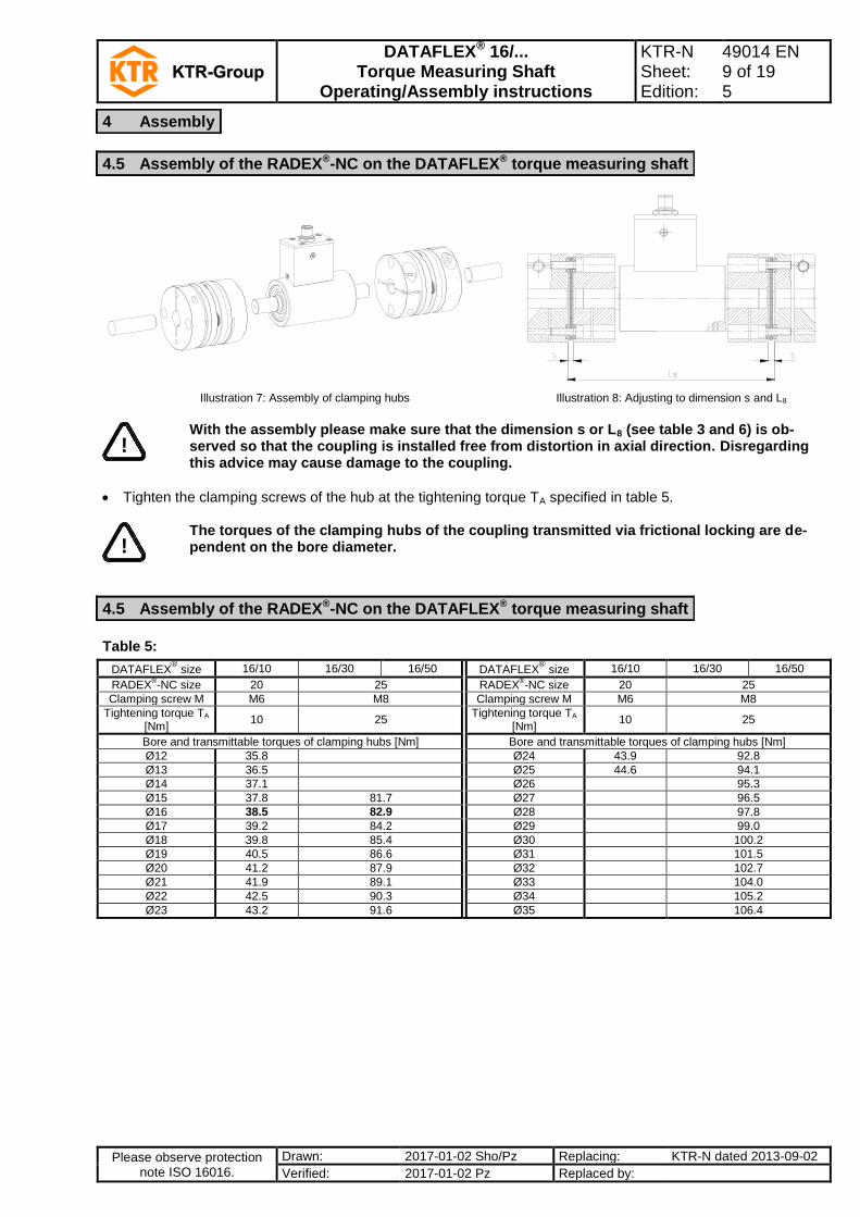
4.5 Assembly of the RADEX®-NC on the DATAFLEX® torque measuring shaft
DATAFLEX® 16/... Torque Measuring Shaft
Operating/Assembly instructions
KTR-N Sheet: Edition:
49014 EN 9 of 19 5
Please observe protection note ISO 16016.
Drawn: 2017-01-02 Sho/Pz Replacing: KTR-N dated 2013-09-02
Verified: 2017-01-02 Pz Replaced by:
Illustration 7: Assembly of clamping hubs Illustration 8: Adjusting to dimension s and L8
!
With the assembly please make sure that the dimension s or L8 (see table 3 and 6) is ob-served so that the coupling is installed free from distortion in axial direction. Disregarding this advice may cause damage to the coupling.
Tighten the clamping screws of the hub at the tightening torque TA specified in table 5.
!
The torques of the clamping hubs of the coupling transmitted via frictional locking are de-pendent on the bore diameter.
Table 5:
DATAFLEX® size 16/10 16/30 16/50 DATAFLEX
® size 16/10 16/30 16/50
RADEX®-NC size 20 25 RADEX
®-NC size 20 25
Clamping screw M M6 M8 Clamping screw M M6 M8
Tightening torque TA [Nm]
10 25 Tightening torque TA
[Nm] 10 25
Bore and transmittable torques of clamping hubs [Nm] Bore and transmittable torques of clamping hubs [Nm]
Ø12 35.8 Ø24 43.9 92.8
Ø13 36.5 Ø25 44.6 94.1
Ø14 37.1 Ø26 95.3
Ø15 37.8 81.7 Ø27 96.5
Ø16 38.5 82.9 Ø28 97.8
Ø17 39.2 84.2 Ø29 99.0
Ø18 39.8 85.4 Ø30 100.2
Ø19 40.5 86.6 Ø31 101.5
Ø20 41.2 87.9 Ø32 102.7
Ø21 41.9 89.1 Ø33 104.0
Ø22 42.5 90.3 Ø34 105.2
Ø23 43.2 91.6 Ø35 106.4
4 Assembly
4.5 Assembly of the RADEX®-NC on the DATAFLEX® torque measuring shaft
4.5 Assembly of the RADEX®-NC on the DATAFLEX® torque measuring shaft

DATAFLEX® 16/... Torque Measuring Shaft
Operating/Assembly instructions
KTR-N Sheet: Edition:
49014 EN 10 of 19 5
Please observe protection note ISO 16016.
Drawn: 2017-01-02 Sho/Pz Replacing: KTR-N dated 2013-09-02
Verified: 2017-01-02 Pz Replaced by:
Illustration 9: Assembly of coupling
Table 6:
DATAFLEX® size 16/10 16/30 16/50
RADEX®-NC size 20 25
Assembly dimensions Dimension s 4 5
Dimension DA 59 70
Dimension LEK 52 69
Screws of lamina set Thread size M6 M6
Tightening torque TA [Nm]
10 14
Fixing the housing
!
The housing must be protected from rotation. For that purpose there is a thread size M4 at the bottom side. Please make absolutely sure to avoid a rigid fixing of the housing!
!
Opening the housing is not required and may cause damage to the measuring shaft.
Degree of protection All DATAFLEX
® measuring shafts type 16 correspond to the protection class IP51 according to DIN EN 60529.
Maintenance The DATAFLEX
® measuring shaft is maintenance-free. Lubrication or cleaning is not necessary.
Calibration The transducer is calibrated when being supplied. We recommend an annual inspection of the calibration.
1. General description
The measuring shafts type DATAFLEX® 16 are provided with wire strain gauges (DMS) the signals of which are
transmitted contactless. In addition, a two-channel shaft encoder provides two speed signals shifted by 90 degrees. Each signal has a resolution of 360 periods per revolution. The measuring shaft is connected to the connection housing DF2 via the connection cable which is available as an accessory.
The measuring shaft should not be switched on before all connections have been properly connected. After initial switch-on the measuring shaft needs about 5 minutes until the warm-up period is finished and the measurement device has its standard accuracy.
4 Assembly
4.6 Advice for assembly of the RADEX®-NC coupling
4.7 Advice for assembly of the DATAFLEX® torque measuring shaft
4.8 Technical description

DATAFLEX® 16/... Torque Measuring Shaft
Operating/Assembly instructions
KTR-N Sheet: Edition:
49014 EN 11 of 19 5
Please observe protection note ISO 16016.
Drawn: 2017-01-02 Sho/Pz Replacing: KTR-N dated 2013-09-02
Verified: 2017-01-02 Pz Replaced by:
2. Connection housing DF2
The connection housing DF2 has 12 screw terminals to connect power supply, display equipment and switches. The torque signal is displayed as proportional direct voltage from -10 … 10 V. For the speed display two square wave signals, one scalable voltage signal and one direction signal are available (for pin configuration see table 7). The button T1 serves for programming and can be bridged externally from GND via the terminal 12 (T1).
Table 7: Pin assignment of the connection housing DF2
No. Description Function Features
Illustration 10: Connection housing DF2
Input operating voltage
10 24V Supply voltage + 24 V DC ± 4 V / 100 mA
11 GND Supply voltage -
Torque output
4 M-U Output voltage + -10 V ... 10 V (RA = 1 k)
5 GND Ground torque output
6 M-I Without function
Speed output pulse signal
7 N1 Speed output channel 1
HTL (24V, 360 pulses/rev.) TTL (5V, 360 pulses/rev.)
8 GND Ground for pulse speed out-put
9 N2 Speed output channel 2
HTL (24V, 360 pulses/rev.) TTL (5V, 360 pulses/rev.)
Speed output DC-voltage
1 R/L Direction signal speed HTL (24V, clockwise = 0) TTL (5V, clockwise = 0)
2 GND Ground for DC speed output
3 N-U Speed of DC voltage output 0 V ... 10 V (scalable)
Other connections / operating devices
12 T1 Push button T1 External push button connec-tion T1
13 L1, L2 Signal LEDs
14 T1, T2 Push button T1, T2 Push button for programming
15 TP Switch low pass filter On/off switch low-pass
16 - Connection of measuring shaft
1:1 Connection cable
17 - Switch for speed scaling see table 11
3. Description of connections a) Supply voltage 24V (No. 10 and 11)
The supply voltage is 24V ± 4V direct current voltage (DC). The current consumption is 100 mA at the maximum. b) Torque signal M-U (No. 4 and 5)
The output voltage is proportional to the torque with an output of values between -10V and 10V. Table 8 shows the relation between torque and output voltage.
4 Assembly
4.8 Technical description

DATAFLEX® 16/... Torque Measuring Shaft
Operating/Assembly instructions
KTR-N Sheet: Edition:
49014 EN 12 of 19 5
Please observe protection note ISO 16016.
Drawn: 2017-01-02 Sho/Pz Replacing: KTR-N dated 2013-09-02
Verified: 2017-01-02 Pz Replaced by:
Table 8: Assignment of torque - output values
DATAFLEX®
Size ΔM / V
16/10 1 Nm / V
16/30 3 Nm / V
16/50 5 Nm / V
Illustration 11: Assignment of torque - output values
c) Filter voltage output (No. 15) The torque signal may be filtered by activating a low-pass filter so that high-frequency parts of the signal are elim-inated. Table 9: Low pass button (No. 15)
Switch position TP Left Right
Low pass on Low pass off
The limit frequency of the filter can be changed by varying the DIP switches (see illustration 12) inside the connection housing:
Illustration 12: Location of DIP switch
4 Assembly
4.8 Technical description

DATAFLEX® 16/... Torque Measuring Shaft
Operating/Assembly instructions
KTR-N Sheet: Edition:
49014 EN 13 of 19 5
Please observe protection note ISO 16016.
Drawn: 2017-01-02 Sho/Pz Replacing: KTR-N dated 2013-09-02
Verified: 2017-01-02 Pz Replaced by:
Table 10: Adjustment of the requested filter frequency
Limit frequency [Hz] Switch 1 Switch 2 Switch 3 Switch 4
2000 OFF OFF OFF OFF
1000 ON OFF OFF OFF
100 OFF ON OFF OFF
10 OFF OFF ON OFF
1 OFF OFF OFF ON
A filter frequency of 1000 Hz is preset.
d) Speed signals N1, N2, N-U, R/L (No. 1, 3, 7, 9)
The connection housing DF2 has 4 connections for speed output:
Two square-wave signals shifted by 90 degrees (N1, N2)
A scalable voltage output (N-U) with direction signal (R/L)
Illustration 13
Outputs N1 and N2
Each of the speed outputs N1 and N2 provide a square-wave signal with a resolution of 360 periods per revolu-tion (illustration 14).
Illustration 14
The speed is calculated as follows: N [rpm] = f [Hz] / 6
The speed channel signals N1 and N2 have a phase shift of 90 degrees to each other. Depending on the rota-tional direction one of the two signals leads 90° in phase (illustration 15).
Clockwise
Illustration 15
4 Assembly
4.8 Technical description

DATAFLEX® 16/... Torque Measuring Shaft
Operating/Assembly instructions
KTR-N Sheet: Edition:
49014 EN 14 of 19 5
Please observe protection note ISO 16016.
Drawn: 2017-01-02 Sho/Pz Replacing: KTR-N dated 2013-09-02
Verified: 2017-01-02 Pz Replaced by:
Output circuit (connection N1 and N2) The speed outputs N1 and N2 have short-circuit proof push-pull outputs providing a square-wave voltage with an ampli-tude of 24V and a maximum switching current of 30 mA. The output terminals must not be charged with an external voltage (see illustration 16). The output voltage of speed lines and torsional direction line can be varied by modifying the jumper position in the connec-tion housing to 5V level (see illustration 17).
Illustration 16: Output circuit of speed outputs
Illustration 17: Modification of voltage level for the speed signal/direction signal
4 Assembly
4.8 Technical description

DATAFLEX® 16/... Torque Measuring Shaft
Operating/Assembly instructions
KTR-N Sheet: Edition:
49014 EN 15 of 19 5
Please observe protection note ISO 16016.
Drawn: 2017-01-02 Sho/Pz Replacing: KTR-N dated 2013-09-02
Verified: 2017-01-02 Pz Replaced by:
Outputs N-U and R/L The KTR connection housing DF02 has an integrated f/U converter which converts the square wave signals of the en-coder into a linear DC voltage output (terminal N-U) and gen-erates an additional signal for the rotational direction (termi-nal R/L). On the bottom side of the connection housing DF02 there is a sixfold multiple switch allowing to adapt the scaling of the speed signal to the type of measuring shaft and the speed range (see illustration 10 and 18).
Illustration 18: Switch positions
Scaling of the speed direct voltage output Table 11: Switch position S1-S4 and the corresponding scale of the speed output N-U
Max. speed Scaling S1 S2 S3 S4
Illustration 19
10 1 rpm / V 0 0 0 0
20 2 rpm / V 0 0 0 1
40 4 rpm / V 0 0 1 0
60 6 rpm / V 0 0 1 1
80 8 rpm / V 0 1 0 0
100 10 rpm / V 0 1 0 1
200 20 rpm / V 0 1 1 0
400 40 rpm / V 0 1 1 1
600 60 rpm / V 1 0 0 0
800 80 rpm / V 1 0 0 1
1000 100 rpm / V 1 0 1 0
2000 200 rpm / V 1 0 1 1
4000 400 rpm / V 1 1 0 0
6000 600 rpm / V 1 1 0 1
8000 800 rpm / V 1 1 1 0
10000 1000 rpm / V 1 1 1 1
Table 12: Selection of DATAFLEX
® series
DATAFLEX® type S5 S6
DATAFLEX® 85/140 0 0
DATAFLEX® 16 1 1
DATAFLEX® 32, 42 (red) 0 1
DATAFLEX® 70 1 0
Table 13: Direction signal
Output voltage R/L Torsional direction The signal of the speed direction output R/L shows the rotational direction (see table 13). 0 Clockwise
24V Counter-clockwise
* Switching between 5V 24V possible (see illustration 17 Modification of voltage level for the speed sig-nal/direction signal)
4 Assembly
4.8 Technical description

DATAFLEX® 16/... Torque Measuring Shaft
Operating/Assembly instructions
KTR-N Sheet: Edition:
49014 EN 16 of 19 5
Please observe protection note ISO 16016.
Drawn: 2017-01-02 Sho/Pz Replacing: KTR-N dated 2013-09-02
Verified: 2017-01-02 Pz Replaced by:
e) Control buttons and LEDs (No. 12 to 14 and illustration 20)
The connection housing DF02 has control switches and LEDs for offset adjustment and sensor test. For reasons of safety the sensor test can only be performed during the first 15 seconds after switching on. The zero adjust-ment can be performed after a turn-on period of 15 seconds (illustration 21). The termination of the 15 seconds period is signalized by a short blinking of the LEDs of the connection housing.
Illustration 20
Automatic zero adjustment (illustration 21) If the „push button“ T1 is activated for a period of 2 seconds, the output of the torque signal is automatically set to 0 Volt. The adjusting is effected irrespective of the amount of the actual torque. The termination of the adjustment is confirmed by fast blinking of the LED L1. The new zero point has been saved and the device is in the measuring mode again.
The automatic zero adjustment can only be performed if the measuring shaft is switched
on for more than 15 seconds.
If necessary, the automatic zero adjustment can be performed by an external control, too. If the potential of the terminal clamp T1 is connected with GND for 2 seconds, an auto-matic zero adjustment is performed.
Illustration 21: Automatic zero adjustment
4 Assembly
4.8 Technical description

DATAFLEX® 16/... Torque Measuring Shaft
Operating/Assembly instructions
KTR-N Sheet: Edition:
49014 EN 17 of 19 5
Please observe protection note ISO 16016.
Drawn: 2017-01-02 Sho/Pz Replacing: KTR-N dated 2013-09-02
Verified: 2017-01-02 Pz Replaced by:
Manual zero adjustment The zero point of the torque output can be adjusted manually. For this purpose both push buttons T1 and T2 are activated simultaneously for 2 seconds. The LED L1 is blinking four times. Pressing the push button T1 increases the voltage, pressing the push button T2 decreases the voltage. The modi-fications are accelerated if the corresponding push button is pressed permanently. Each amendment is confirmed by short blinking of the LED L2. Having performed the adjusting the new values are stored lastingly by pressing both push buttons again for 2 seconds. The LED L1 is illuminated once and signalizes the return to the measuring mode.
The manual zero adjustment can only be performed if the measuring shaft is switched on
for more than 15 seconds and the signal has levelled off.
Illustration 22: Manual zero adjustment
Sensor test During the first 15 seconds after powering up the torque sensor can be inspected for operativeness.If the push button T2 is pressed for 2 seconds the torque voltage output will be increased by approx. 4 Volt for the period of 2 seconds.
The sensor test can only be performed during the first 15 seconds after switching on.
Illustration 23: Sensor test
4 Assembly
4.8 Technical description

DATAFLEX® 16/... Torque Measuring Shaft
Operating/Assembly instructions
KTR-N Sheet: Edition:
49014 EN 18 of 19 5
Please observe protection note ISO 16016.
Drawn: 2017-01-02 Sho/Pz Replacing: KTR-N dated 2013-09-02
Verified: 2017-01-02 Pz Replaced by:
In respect of environmental protection we would ask you to dispose of the packaging or products on termination of their service life in accordance with the legal regulations and standards that apply, respectively.
DATAFLEX
® is a low-maintenance torque measuring shaft. We recommend to perform a visual inspection on the
torque measuring shaft at least once a year. Please pay special attention to the condition, alignment and screw connection of the torque measuring shaft and the condition of the lamina sets of the RADEX
®-N coupling.
!
Having started up the torque measuring shaft the tightening torques of the screws have to be inspected during the usual inspection intervals.
Please consider our operating/assembly instructions KTR-N 47110 additionally when using the RADEX
®-N coupling.
If requested, we are pleased to perform the calibration of your torque measuring shaft and other services. Contact addresses of the KTR partners for spare parts and orders can be obtained from the KTR homepage at www.ktr.com.
KTR does not assume any liability or warranty for the use of spare parts and accessories which are not provided by KTR and for the damages which may incur as a result.
5 Disposal
6 Maintenance and service
7 Services, customer service addresses

DATAFLEX® 16/... Torque Measuring Shaft
Operating/Assembly instructions
KTR-N Sheet: Edition:
49014 EN 19 of 19 5
Please observe protection note ISO 16016.
Drawn: 2017-01-02 Sho/Pz Replacing: KTR-N dated 2013-09-02
Verified: 2017-01-02 Pz Replaced by:
EC Certificate of conformity The manufacturer - KTR Systems GmbH, D-48432 Rheine - states that the
DATAFLEX® torque measuring shaft described in the present operating/assembly instructions is in accordance with the following directive:
2014/30/EU Directive of the European Parliament and European Council dated February 26. 2014 for harmonizing the legal provisions of the member states regarding electromagnetic compatibility
Standards applied: DIN EN 61000-6-2: Interference immunity for industrial environments DIN EN 61000-4-2: Electrostatic discharge immunity test (ESD) DIN EN 61000-4-3: Radiated, radio-frequency, electromagnetic field immunity test DIN EN 61000-4-4: Electrical fast transient/burst immunity test DIN EN 61000-4-6: Immunity to conducted disturbances, induced by radio-frequency fields DIN EN 61000-6-4: Emission for industrial environments DIN EN 55011: Intensity of radio interference area (class B)
Rheine, 2017-01-02 i. V.
i. A.
Place Date Reinhard Wibbeling Engineering/R&D
Jürgen Kösters Product Manager
8 EC Certificate of conformity