datasheet 40gbase qsfp+ to 4 sfp+ passive copper … · signals not supported in sfp+ copper...
TRANSCRIPT

40GBASE QSFP+ to 4 SFP+ Passive Copper Breakout Direct Attach Cable (PCC)
Features
• InfiniBand4x SDR, DDR, QDR• 10G/40Gigabit Ethernet• Switches, Routers, and HBAs• SAS & Fiber Channel• Rack-to-Rack, Shelf-to-Shelf
Interconnect• Enterprise & Data Center Networking & Storage• ATM/SDH/SONET
Application
Optical Communication System
1
Datasheet
• Connector 1: QSFP+ 40GBASE Rated Connector (SFF-8436 Compliant)
• Connector 2: 4 x SFP+ 10GBASE Rated Connector (SFF-8431 Compliant)
• Up to 10.3125GBASE transfer rate per SFP+ channel (40GBASE aggregate)
• Cable Type: Passive Copper Cable• Wire AWG: AWG30• Available lengths (in meters): 0.5, 1, 2,
3.....• Hot plug swappable• Commercial temperature range (COM): 0~ 70 °C• Low power consumption: 0.02W (typ.)• Power supply :+3.3V• Low cross-talk and pair-to-pair skew
maintains signal integrity• Fully compliant to the latest SFP+ & QSFP
MSA• RoHS compatible

Optical Communication System
2
Datasheet
Description
Product Specifications
I. Absolute Maximum Ratings
Fiberstore’s QSFP+ to 4 x SFP+ passive copper cables are 40Gb/s to 10Gb/s cable assemblies. The cables are compliant with SFF-8431 and SFF-8436 specifications and provide connectivity between devices using QSFP+ port on one end and multiple SFP+ ports on the other end. Each QSFP+ to SFP+ cable features a single QSFP+ connector (SFF-8436) rated for 40-Gb/s on one end and 4 SFP+ connectors (SFF-8431), each rated for 10-Gb/s, on the other. The cables use state-of-the-art signal processing technology to fill the expanding need for cost effective data center intercon-nects.
Fiberstore’s unique quality passive copper cable solutions provide power-efficient replacement for active power connectivity such as fiber optic cables. The QSFP+ to 4 x SFP+ cables provide 40GbE systems the ability to connect to 10GbE switches or adapter cards. Optimizing systems to operate with Fiberstore’s QSFP+ to 4 x SFP+ passive copper cables significantly reduce power consumption and enlarge the connectivity opportunities of the system. Rigorous cable production testing ensures best out-of-the-box installation experience, performance and durability.
Note: 1. Damage may occur if the transceiver is subjected to conditions beyond the limits.
Parameter Symbol Min Typical Max Unit
Operating Case Temperature Tc 0 +70 °C
Power Supply Voltage VCC3 3.135 3.3 3.465 V
Relative Humidity (non-condensation) RS - 85 %
Power Dissipation PD 1.5 W
Optical Communication System
3
Datasheet
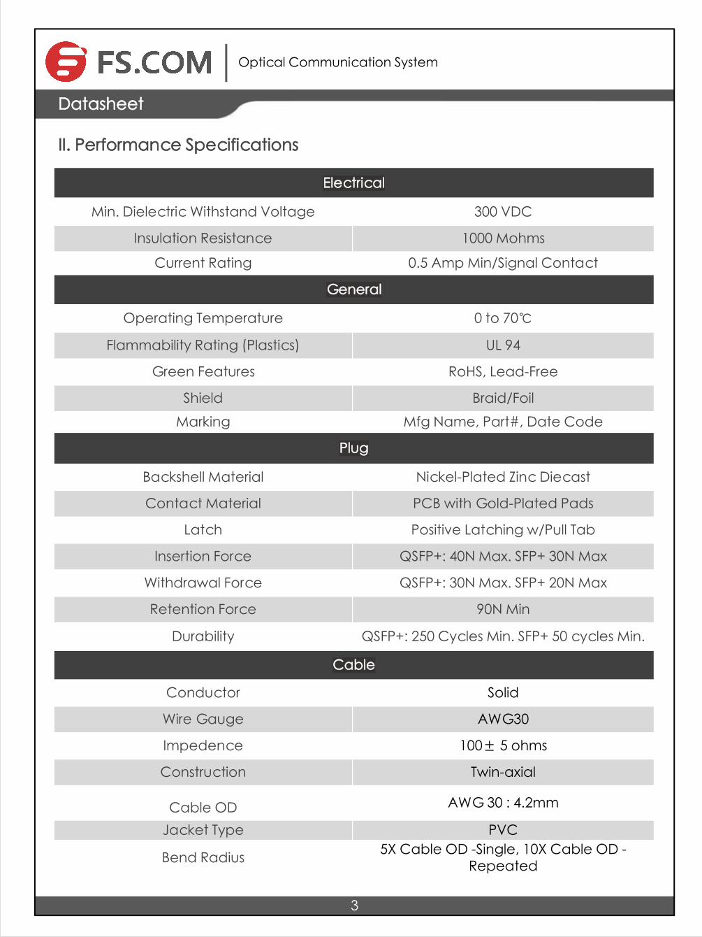
II. Performance Specifications
Electrical
Min. Dielectric Withstand Voltage 300 VDC
Insulation Resistance 1000 Mohms
Current Rating 0.5 Amp Min/Signal Contact
General
Operating Temperature 0 to 70℃
Flammability Rating (Plastics) UL 94
Green Features RoHS, Lead-Free
Shield Braid/FoilMarking Mfg Name, Part#, Date Code
Plug
Backshell Material Nickel-Plated Zinc Diecast
Contact Material PCB with Gold-Plated Pads
Latch Positive Latching w/Pull Tab
Insertion Force QSFP+: 40N Max. SFP+ 30N Max
Withdrawal Force QSFP+: 30N Max. SFP+ 20N Max
Retention Force 90N Min
Durability QSFP+: 250 Cycles Min. SFP+ 50 cycles Min.
Cable
Conductor Solid
Wire Gauge AWG30
Impedence 100± 5 ohms
Construction Twin-axial
Cable OD AWG 30 : 4.2mm
Jacket Type PVC
Bend Radius 5X Cable OD -Single, 10X Cable OD - Repeated

Optical Communication System
Datasheet
4
III. Electrical Characteristics
Test Type Test Item 24AWG 26AWG 28AWG 30AWG
Electrical Characteristics
Differential impedance
100±5Ω @ TDR
100±5Ω 100±5Ω 100±5Ω @ TDR
Mutual capacitance
14pF/ft nominal
14pF/ft nominal
14pF/ft nominal
14pF/ft nominal
Time delay
1.31ns/ft nominal, (4.3ns/m) nominal
1.35ns/ft nominal
1.35ns/ft nominal
1.35ns/ft nominal, (4.3ns/m) nominal
Time delay skew (within pairs)
80ps/10m maximum
120ps/8.5m maximum
120ps/7m maximum
50ps/5.5m maximum
Time delay skew (between pairs)
350ps/10m maximum
500ps/8.5m maximum
500ps/7m maximum
350ps/5.5m maximum
Attenuation10dB/10m
maximum @ 1.25Ghz
10dB/8.5m maximum @
1.25Ghz
10dB/7m maximum @
1.25Ghz
8.4dB/5.5m maximum @
1.25Ghz
Conductor DC Resistance
0.026Ω/ft maximum @20°C
0.04Ω/ft maximum @20°C
0.06Ω/ft maximum @20°C
0.01Ω/ft maximum @20°C
Physical Characteristics
Conductors(two pair)
24AWG Solid, Silver plated
copper
26AWG Solid, Silver plated
copper
28AWG Solid, Silver plated
copper
30AWG Solid, Silver plated
copper
Insulation Foam polyolefin
Foam polyolefin
Foam polyolefin
Foam polyolefin
Pair drain wire26AWG Solid, Silver plated
copper
28AWG Solid, Silver plated
copper
30AWG Solid, Silver plated
copper
30AWG Solid, Silver plated
copper
Overall cable shield
Aluminum/polyester tape,
125% coverage, Tin
plated copper braid, 38AWG, 85%
coverage
Aluminum/polyester tape,
125% coverage, Tin
plated copper braid, 38AWG, 85%
coverage
Aluminum/polyester tape,
125% coverage, Tin
plated copper braid, 38AWG, 85%
coverage
Aluminum/polyester tape,
125% coverage, Tin plated
copper braid,
38AWG, 85% coverage
Outer diameter 6.0mm 5.2mm 4.7mm 4.2mm

Optical Communication System
IV. QSFP+ Pin Descriptions
5
Datasheet
Pin Logic Symbol Name/Description Notes
1 GND Module Ground 1
2 CML-I Tx2n Transmitter Inverted Data Input
3 CML-I Tx2p Transmitter Non-Inverted Data Input
4 GND Module Ground 1
5 CML-I Tx4n Transmitter Inverted Data Input
6 CML-I Tx4p Transmitter Non-Inverted Data Input
7 GND Module Ground 1

Optical Communication System
6
Datasheet
8 LVTTL-I ModSelL Module Select 2
9 LVTTL-I ResetL Module Reset 2
10 Vcc Rx +3.3 V Receiver Power Supply
11 LVCMOS-I SCL 2-wire Serial Interface Clock 2
12 LVCMOS-I/O SDA 2-wire Serial Interface Data 2
13 GND Module Ground 1
14 CML-O Rx3p Receiver Non-Inverted Data Output
15 CML-O Rx3n Receiver Inverted Data Output
16 GND Module Ground 1
17 CML-O Rx1p Receiver Non-Inverted Data Output
18 CML-O Rx1n Receiver Inverted Data Output
19 GND Module Ground 1
20 GND Module Ground 1
21 CML-O Rx2n Receiver Inverted Data Output
22 CML-O Rx2p Receiver Non-Inverted Data Output
23 GND Module Ground 1
24 CML-O Rx4n Receiver Inverted Data Output
25 CML-O Rx4p Receiver Non-Inverted Data Output
26 GND Module Ground 1
27 LVTTL-O ModPrsL Module Present, internal pulled down to GND

Optical Communication System
7
Datasheet
28 LVTTL-O IntL Interrupt output, should be pulled up on host board 2
29 Vcc Tx +3.3 V Transmitter Power supply
30 Vcc 1 +3.3 V Power Supply
31 LVTTL-I LPMode Low Power Mode 2
32 GND Module Ground 1
33 CML-I Tx3p Transmitter Non-Inverted Data Input
34 CML-I Tx3n Transmitter Inverted Data Input
35 GND Module Ground 1
36 CML-I Tx1p Transmitter Non-Inverted Data Input
37 CML-I Tx1n Transmitter Inverted Data Input
38 GND Module Ground 1
Notes: 1. GND is the symbol for signal and supply (power) common for the QSFP+ module. All are common within the QSFP+ module and all module voltages are referenced to this potential unless otherwise noted. Connect these directly to the host board signal-common ground plane.
2. Vcc Rx, Vcc1 and Vcc Tx are the receiver and transmitter power supplies and shall be applied concurrently. Recommended host board power supply filtering is shown below. Vcc Rx, Vcc1 and Vcc Tx may be internally connected within the QSFP+ Module module in any combination. The connector pins are each rated for a maximum current of 500 mA.

Optical Communication System
8
Datasheet
V. Recommended power supply filtering Example of QSFP Host board schematics
A typical host board mechanical layout for attaching the QSFP+ transceiver is presented below. The recommended host electrical connector should be a 38-pin IPASS right angle connector assembly and the cage assembly should be QSFP+ single cage.

Optical Communication System
9
Datasheet
VI. SFP+ Pin Descriptions
Pin Logic Symbol Name/Description Notes
1 VeeT Transmitter Ground
2 LV-TTL-O TX-Fault N/A 1
3 LV-TTL-I TX-DIS Transmitter Disable 2
4 LV-TTL-O SDA Tow Wire Serial Data
5 LV-TTL-I SCL Tow Wire Serial Clock
6 MOD-DEF0 Module present, connect to VeeT
7 LV-TTL-I RS0 N/A 1
8 LV-TTL-O ROS LOS of Signal 2
9 LV-TTL-I RS1 N/A 1
10 VeeR Receiver Ground
11 VeeR Receiver Ground
12 CML-O RD- Receiver Data Inverted
13 CML-O RD+ Receiver Data Non-Inverted

Optical Communication System
10
Datasheet
14 VeeR Receiver Ground
15 VccR Receiver Supply 3.3 V
16 VccT Transmitter Supply 3.3 V
17 VeeT Transmitter Ground
18 CML-I TD+ Transmitter Data Non-Inverted
19 CML-I TD- Transmitter Data Inverted
20 VeeT Transmitter Ground
Notes: 1. Signals not supported in SFP+ Copper pulled-down to VeeT with 30K ohms resistor 2. Passive cable assemblies do not support LOS and TX_DIS

11
Optical Communication System
Datasheet
VII. Recommended Wiring Diagram

12
Optical Communication System
DatasheetDatasheet
VIII. High Speed Interconnect

Optical Communication System
Datasheet
13
IX. Installation
Caution: Follow accepted ESD practices when handling QSFP+/SFP+ connectors to prevent damage to the internal components within the connector. ESD (electrostatic discharge) is the sudden flow of electricity between two objects at different voltage potentials caused by contact. The basis of any ESD protection strategy is to ground or bring all elements in the ESD protected area to the same potential. An ESD wrist strap should be used for everything in the ESD protected area including personnel, tools, cabinets and components.
A. Installing QSFP+/SFP+ Modules
Follow these steps to install a Fiberstore QSFP+/SFP+ cable assembly:Step 1. Remove the protective ESD cap from the connectorStep 2. Slide the QSFP+/SFP+ cable end into the slot until it locks into position (see figure 1). There is an audible click when the connector is properly seated.
Figure 1. Installing an QSFP+/SFP+ Module
Figure 2. Disconnecting Latch Mechanism
Figure 3. Removing Modules
Caution : The latching mechanism locks the QSFP+/SFP+ connector into place when cables are connected. Do not pull on the cable in an attempt to remove the QSFP+/SFP+ connector.
B. Removing QSFP+ Modules
Follow these steps to remove a Fiberstore QSFP+/SFP+ cable assembly:Step 1. Pull on the QSFP+/SFP+ latch pull lanyard. See figure 2.Step 2. Grasp the QSFP+/SFP+ connector on both sides and remove it from the system. See figure 3.Step 3. If possible, replace the ESD protective cap or put the QSFP+/SFP+ into an ESD protected bag.

Optical Communication System
Datasheet
14
X. Mechanical Dimensions

+86 (755) 8300 3611 [email protected] www.
Copyright © 2009-2015 Fiberstore
Test Center
Copyright © 2009-2015 Fiberstore
Only when quality and 100% compatibility is verified and proved do our modules enter the market. This depends on Fiberstore test center which is supported by a variety of mainstream original brand switches and professional staff. We are proud of this test center and believe all of these devices worth the investments, because it brings the best to our customers.
The original switches could be found nowhere but at Fiberstore's test center, eg: Juniper MX960 & EX 4300 series, Cisco Nexus 9396PX & Cisco ASR 9000 Series, HP 5900 Series & HP 5406R ZL2 V3(J9996A), Arista 7050S-64, Brocade ICX7750-26Q & ICX6610-48, Avaya VSP 7000 MDA 2, etc.
Optical Communication System
15
Datasheet
Cisco ASR 9000 Series(A9K-MPA-1X40GE) ARISTA 7050S-64(DCS-7050S-64) Juniper MX960
Brocade ICX 7750-26Q Extreme Networks X670V VIM-40G4X Mellanox M3601Q
Dell N4032F HP 5406R ZL2 V3(J9996A) AVAYA 7024XLS(7002QQ-MDA)

Test Assured Program
Our smart data system allows effective product management an d q u a l i t y control according to the unique serial number, properly t racing the order, shipment and every part.
Our in-house coding facility programs all of our parts to standard OEM specs for compatibility on all major vendors and systems such as Cisco, Juniper, Brocade, HP, Dell, Arista and so on.
Fiberstore truly understands the value of compatibility and interoperability to each optics. Every module Fiberstore provides must run through programming and an extensive series of platform diagnostic tests to prove its performance and compatibility. In our test center, we care of every detail from staff to facilities—professionally trained staff, advanced test facilities and comprehensive original-brand switches, to ensure our customers to receive the optics with superior quality.
With a comprehensive line of original-brand switches, we can recreate an environment and test each optics in practical application to ensure quality and distance.
The last test assured step to ensure our products to be shipped with perfect package.
Optical Communication System
16
Datasheet

Page 5 of 6
Copyright © 2009-2015 Fiberstore Copyright © 2009-2015 Fiberstore
[email protected] FS.COM
Optical Communication System
17
Datasheet
Order Information
Part NumberData Rate
LengthWire
GaugeConnector
TypeTemp. Range
Cable Jacket
QSFP-4SFP10G-DAC-0.5 Up to 40G 0.5m AWG30 QSFP+ to 4SFP+ 0-70 °C PVC
QSFP-4SFP10G-DAC-1 Up to 40G 1m AWG30 QSFP+ to 4SFP+ 0-70 °C PVC
QSFP-4SFP10G-DAC-2 Up to 40G 2m AWG30 QSFP+ to 4SFP+ 0-70 °C PVC
QSFP-4SFP10G-DAC-3 Up to 40G 3m AWG30 QSFP+ to 4SFP+ 0-70 °C PVC
QSFP-4SFP10G-DAC-4 Up to 40G 4m AWG30 QSFP+ to 4SFP+ 0-70 °C PVC
QSFP-4SFP10G-DAC-5 Up to 40G 5m AWG30 QSFP+ to 4SFP+ 0-70 °C PVC
Notes: 1. All our 40G QSFP to 4 SFP+ PCCs are 100% compatible with major brands like Cisco, Juniper, Enterasys, Extreme, H3C ect. 2. Customized 40G QSFP to 4 SFP+ PCCs are available in various lengths. 3. The wire gauge can be customized if it is required, like AWG24, AWG26, AWG28 and AWG30.

Fiberstore U.K.Third Floor 207 Regent Street, London, W1B 3HH, United KingdomTel: +44 (020) 3287 6810
Fiberstore U.S. 331 Andover Park East Ste330, Tukwila, WA 98188, United StatesTel: +1-425-226-2035Fax: +1-253-246-7881
Fiberstore Hong Kong1220 Tung Chun Commercial Centre, 438-444 Shanghai Street, Kowloon, HongKongTel: +(852) 817 636 06Fax: +(852) 817 636 06
Fiberstore ChinaRoom 301, Third Floor, Weiyong Building, No. 10 Kefa Road, Nanshan District, Shenzhen, 518057, ChinaTel: +86 (755) 8300 3611Fax: +86 (755) 8326 9395
Copyright © 2009-2015 Fiberstore Copyright © 2009-2015 Fiberstore
Addresses, phone number and fax number also have been listed at www.fs.com. Please e-mail us at [email protected] or call us for assistance.
All statements, technical information, and recommendations related to the products here are based upon information believed to be reliable or accurate. However, the accuracy or completeness thereof is not guaranteed, and no responsibility is assumed for any inaccuracies. Please contact FS for more information.
Contact Us
Fiber Optic Transceivers Copyright © 2009-2016 FS.COM All Rights Reserved.
Optical Communication System
Datasheet