date first printed: august, 2017 performance testing of ...€¦ · hydrostatic pressure tests on...
TRANSCRIPT

ENGINEERING GUIDELINE
Concrete Pipe Associationof Australasia
Performance Testing of
Installed Non-Pressure
Rubber Ring Jointed
Concrete Stormwater
Pipelines
Date first printed: August, 2017
Contents
1.0 INTRODUCTION 3
2.0 REVIEW DETAILS 4
3.0 OVERVIEW OF TEST METHODS 43.1 Hydrostatic Testing 43.2 Individual Joint Test 43.3 Air Testing 4
4.0 HYDROSTATIC TESTING NON – PRESSURE PIPELINES 54.1 Introduction 54.2 Purpose of Test 54.3 Test Criteria 54.4 Preparation and Procedure 54.5 Test Acceptance 6
5.0 INDIVIDUAL HYDROSTATIC JOINT TESTING 65.1 Introduction 65.2 Test Criteria 75.3 Precautions, Preparation and Procedure 75.4 Test Acceptance 7
6.0 AIR TESTING NON - PRESSURE PIPELINES 86.1 Introduction 86.2 Important features of Air Testing 86.3 Test Criteria 96.4 Preparation and Procedure 96.5 Test Acceptance 96.6 Safety Aspects 9
APPENDIX A 10Hydrostatic Test Procedure for Installed Non-Pressure
Rubber Ring Jointed Concrete Stormwater Pipelines
APPENDIX B 11Air Test Procedure for Installed Non-Pressure Rubber Ring
Jointed Concrete Stormwater Pipelines
APPENDIX C 12Process adopted in the CPAA review of testing Procedures
E N G I N E E R I N G G U I D E L I N E
2
CPAA wishes to acknowledge the assistance of Independent Pipeline Services Limited for providing the test equipment and resources and Schick Civil Construction Limited for providing site access and a suitable pipe trench for the photography.
1.0 Introduction
Steel Reinforced Concrete Pipes in Australia and New Zealand are designed, manufactured, and factory
tested to AS/NZS 4058. Rubber ring jointed concrete pipes manufactured to this Standard have a jointing system providing a watertight pipeline when properly installed. AS/NZS 4058 makes provision for routine watertightness testing of this type of pipe when specified.
In many cities around the world, infiltration and exfiltration in sewerage networks present a challenge for engineers to address when planning new network construction. Hydrostatic pressure, or the more convenient air pressure or vacuum testing, are usually specified to assure pipeline capability to handle wastewater without allowing infiltration or exfiltration. Typically, this infiltration or exfiltration is via joints or defects and is independent of the pipe material used.
For Stormwater pipelines and culverts, watertightness is often a secondary requirement as lines are often designed with lateral connections. These connections are typically to various subsoil drains, making the pipe system open in both directions to the ground water system. For this reason, non-watertight pipes such as flush joint pipes are acceptable in such installations.
Performance testing, hydrostatic or air, of non-pressure concrete Stormwater pipelines is not necessary
in most installations as the performance of the concrete pipe structure is tested during manufacture.
In some specific Stormwater installations, these per- formance tests may be prudent in certain circumstances when exfiltration or infiltration may affect the stability, geotechnical or hydraulic performance of the infrastructure, structures, and buildings where it is installed, or the stability of pipeline itself such as pipelines along top or bottom of steep embankments prone to slips.
Table 1 below summarises the options where watertightness/air testing is appropriate as part of quality assurance of the pipeline integrity.
However, it is generally understood that the level of watertightness required for most Stormwater pipelines is less than that required for wastewater and it is appropriate to specify different acceptance criteria to those specified for wastewater lines.
Asset Owners generally specify visual inspection or CCTV inspection to evaluate the conformance of installation of Stormwater concrete pipes to project or Asset Owner specifications. Some Asset Owners prefer watertightness or air testing as a quantitative test for installation quality assurance rather than the qualitative CCTV test. Whilst appropriate in principle, there is considerable variability in acceptance criteria and test procedures specified. There is often variability in the interpretation of the test results and there is often no differentiation between Sewer and Stormwater
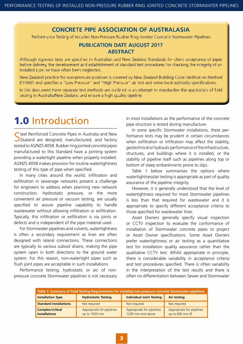
CONCRETE PIPE ASSOCIATION OF AUSTRALASIA
PUBLICATION DATE AUGUST 2017ABSTRACT
3
PERFORMANCE TESTING OF INSTALLED NON-PRESSURE RUBBER RING JOINTED CONCRETE STORMWATER PIPELINES
Table 1: Summary of Field Testing Requirements for installed non-pressure concrete Stormwater pipelines
Installation Type Hydrostatic Testing Individual Joint Testing Air testing
Standard Installations Not required Not required Not required
Complex/critical Appropriate for pipelines Appropriate for pipelines Appropriate for pipelinesinstallations up to 1050 mm 1200 mm and above up to 600 mm Ø

installations, or pipe materials used. Similarly, New Zealand Building Code Verification Method E1/VM1 specifies a “Low Pressure” and “High Pressure” air test for pipelines up to 225mm diameter without mentioning pipeline length or material.
The existing Concrete Pipe Association of Australasia (CPAA) Technical Bulletin Field Testing of Pipelines and Joints, (2nd Edition 1995, revised 2011) does not distinguish between sewer and Stormwater applications. The test procedures therein were developed for sewer pipelines and are considered too conservative and not appropriate for Stormwater. In addition, significant changes have occurred since 1995, in overseas Standards and Specifications to account for changes in technology and Health and Safety requirements for site testing.
This document “Performance testing of installed non-pressure concrete Stormwater pipelines” has been developed following a comprehensive review covering existing specifications and field testing experience from both Australia, New Zealand and overseas. The aim of this document is to provide field testing guidance specific to non-pressure concrete Stormwater pipelines and to standardize the application of these tests in Australia and New Zealand.
Field testing of concrete pipelines and joints is applicable only to pipes from production batches which have been subjected to the optional routine factory hydrostatic pressure testing by the manu-facturer, as specified by the user before purchase.
The most reliable proof test of the workmanship in a laid concrete pipeline is by the application of a hydrostatic test but it is not always convenient to carry this out. There can be problems or excessive cost in obtaining water at some locations and then in disposing of it afterwards.
Instead of the hydrostatic test it is possible to apply a low-pressure air test. However, concrete pipelines will tend to show greater and more variable permeability to air than to water, so great care is needed in applying the air test and also in interpreting results. Although results of air tests and water tests do not always correlate, a satisfactory air test can serve as a useful indication that a line will pass a water test.
2.0 Review Details
A thorough review of approaches in other jurisdictions has been undertaken in developing this document.
A summary of the review findings is given in Appendix C for completeness.
3.0 Overview of Test Methods
Various field tests are in use to ensure the integrity of concrete pipelines. These, together with their
correct application are discussed in the following sections and summarised in Table 1 as it is important that these tests are used for the correct reasons and in the correct manner. The various tests are:
3.1 Hydrostatic Testing (Section 4)The purpose of this test is to check that the jointing has been performed correctly and the rubber ring properly located. It is intended to pick up any fault that has occurred during the laying process. Note: barrel integrity would have been confirmed in the factory watertightness testing.
If the ground water is equal or greater than the test pressure (2.4 m above invert level of the pipe) (24 kPa) and the pipe wall or joints are not leaking when viewed by CCTV for pipes less than 1200mm or when visually inspected for larger pipes, the pipeline is considered acceptable and no additional testing is required. Moisture or beads of water appearing on the surface of the joint will not be considered as visible leakage.
3.2 Individual Joint Testing (Section 5)This test is used to establish that each jointing operation has been performed correctly and the rubber ring is in position. It is not appropriate for use on small pipes and is recommended for diameters 1200 mm diameter and above.
3.3 Air Testing (Section 6)This test uses low pressure air and is only applicable where it is more convenient than using the hydrostatic test. It can provide the criteria for acceptance of a pipeline but not for its rejection. When unacceptable leakage rates occur during the air test the contractor has the option to revert to the hydrostatic (water) test.
This test is not recommended for pipes >600 mm diameter because of the large forces to be resisted by the pneumatic plugs.
✦
E N G I N E E R I N G G U I D E L I N E
4

4.0 Hydrostatic Testing Non-Pressure Pipelines
4.1 Introduction
Concrete Stormwater pipes are manufactured to meet the requirements of Australian and New Zealand
Standards. For rubber ring jointed pipe these Standards provide an option for the purchaser to specify routine hydrostatic pressure tests on batches of pipe before it leaves the factory.
To ensure that the pipes are still in good condition and have been correctly laid a low pressure hydrostatic test can also be applied to the pipeline after it has been laid. The test is a good indicator of the integrity of the line because it simulates service conditions. It is relatively simple to perform and can be applied to rubber ring joint Stormwater pipelines with a range of diameters up to 1050 mm diameter. Pressure pipelines, e.g. water supply or irrigation installations, require stricter acceptance criteria.
It should be noted that this field test is not intended to reassess general pipe permeability as the original factory test is designed to do this.
4.2 Purpose of TestWhen the owner or principal requires and specifies that a hydrostatic test is to be carried out, this should be done after laying the pipes and placing haunching, but before completing back-filling. The test is designed to reveal the occurrence of damaged pipes, joints incorrectly installed, or other laying deficiencies.
4.3 Test CriteriaThe pipe when tested under a minimum head of 1.2 metres and a maximum head of 6 metres (12 to 60 kPa of the pipe, shall not show any leakage in excess of 1.54 litres per hour per linear metre per metre of nominal internal diameter. The minimum and maximum heads specified shall be measured above the internal crown of the pipe.
4.4 Preparation and ProcedurePneumatic plugs should be used in the completed pipeline or progressively to sections as laid and at any inlet/outlet connections.
Care is needed in making water tight seals at all plugs. It is recommended that pneumatic plugs are used instead of screw rubber plugs as pneumatic plugs provide a much more effective seal at the pipe walls.
The test can be applied to the completed pipeline or progressively to sections as laid. The test pressure at the high point of the line is to be 1.2 m (12 kPa) above the
5
PERFORMANCE TESTING OF INSTALLED NON-PRESSURE RUBBER RING JOINTED CONCRETE STORMWATER PIPELINES
Figure 1. Hydrostatic Test
crown of the pipe, and the maximum test pressure at the low point in the line is 6 m (60 kPa). Depending on the grade, some pipelines must be tested in stages otherwise maximum head could be exceeded.
The section of the line to be tested is isolated by means of suitable test plugs placed at the upstream and downstream ends of the pipeline. Whenever possible, testing should be carried out from manhole to manhole. Short branch drains connected to a pipeline between manholes should be tested as one system with the main pipeline. Long branches and manholes should be separately tested.
In order to fill the line and obtain the required 1.2 metres head (12 kPa) above the crown at the high point of the test section, a water entry point must be provided through the pneumatic plug at the upstream end. Provision is also required in the upstream plug to bleed air from the line to ensure the line under test is completely filled with water.
The correct head level can be set by attaching a drum or container to a flexible hose passing through the pneumatic plug. The drum which should be calibrated by marking with a litre scale is supported so that the top mark of the scale is at 1.2 metres above the crown of the pipe. This is the reference mark and by noting the amount of water added to maintain the correct level, an estimate of the leakage rate can be quickly obtained.
After filling, the water level will initially fall due to:
• Absorption into the pipe wall,
• Air which is trapped at joints needing time to escape.
Allowance should be made for this by adding water to maintain some head on the pipe for an appropriate stabilising period before the measuring time commences. This stabilising time will depend on factors such as the age of the pipes, their moisture condition, ambient conditions, etc. It will usually be of the order of 24 hours. Whilst the aim is to commence the test proper as soon as possible, the appropriate period will best be determined by conferring with the pipe suppliers.
Provision must be made during the filling and stabilising period to bleed air from the line to ensure that no air remains trapped in the line.
At the end of the stabilising period the head of water is adjusted back to the correct level. The loss of water over a period of 30 minutes, or 1 hour, is measured by adding water and noting the quantity required to maintain the correct water level. Figure 1 shows a typical arrangement.
4.5 Test AcceptanceThe pipeline is acceptable if the leakage measured does not exceed 1.54 litres per hour per linear metre per metre of nominal internal diameter.
Water loss in excess of the specified rate may be due to a defect. The line should be inspected and if a defect is detected by visible signs of leakage then remedial action is to be taken.
If no defect is found, it may be that the stabilising period was insufficient and after waiting for a further period of time the test should be repeated.
5.0 Individual Hydrostatic Joint Testing
5.1 Introduction
Joint hydrostatic testing is generally limited to pipes of internal diameter 1200 mm and upwards. Physical
access (person entry) into smaller diameters makes individual joint testing impracticable.
The purpose of a joint test is to establish the integrity of the joint. It is not equivalent in any way to a performance test for the line at full pressure. However, it requires very little water and the equipment is simple and safe to use.
Note: If the ground water is equal or greater than the test pressure (2.4 m above invert level of the pipe) (24 kPa) and the pipe wall and the joints are not leaking when viewed by CCTV or when visually inspected, no additional testing is required. Moisture or beads of water appearing on the surface of the joint will not be considered as visible leakage.
The joint in the pipeline to be tested is covered on the inside of the pipe by a ring with two end-element sealing tubes. Once the sealing tubes have been pressurized to form a seal around the joint, low pressure water is introduced through a connection on the ring into the annular space between the sealing ring and the joint. After the pressure is stabilized, the pressure drop (if any) is timed. Joint testing equipment is available from a number of suppliers worldwide.
5.2 Test CriteriaThe test criteria have been adopted from ASTM C1103M – 03 “Standard Practice for Joint Acceptance Testing of Installed Precast Concrete Pipe Sewer Lines”.
E N G I N E E R I N G G U I D E L I N E
6
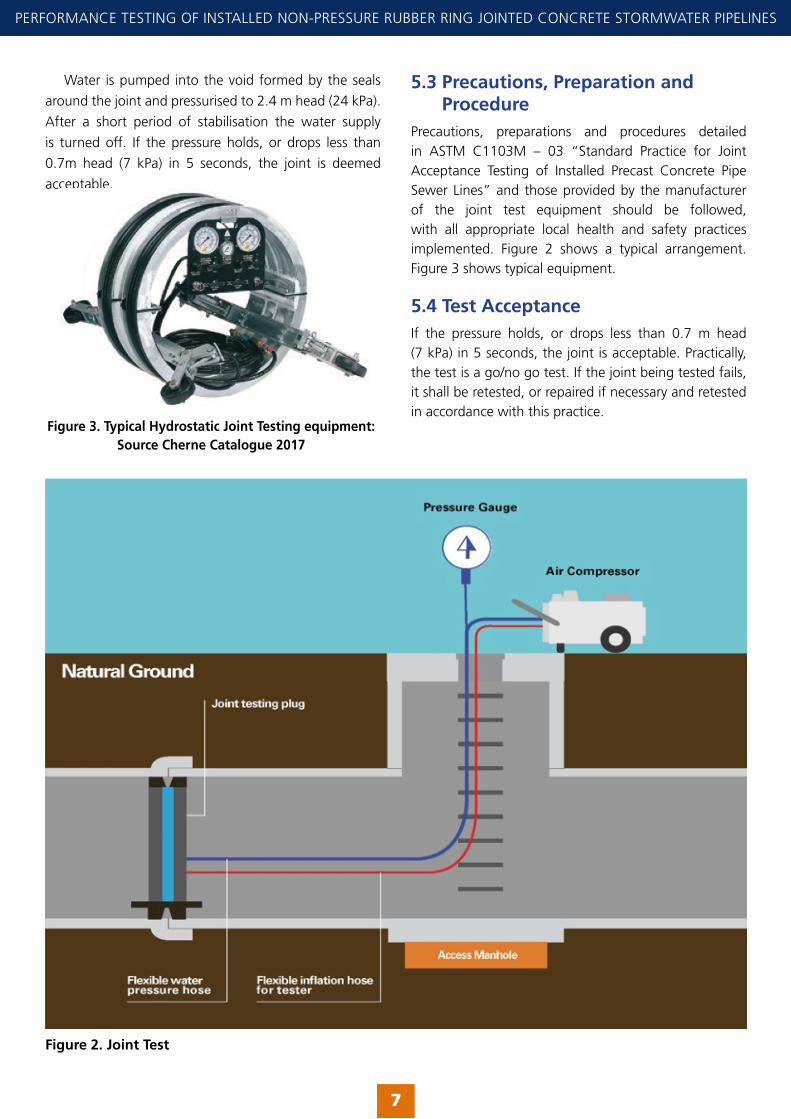
Water is pumped into the void formed by the seals
around the joint and pressurised to 2.4 m head (24 kPa).
After a short period of stabilisation the water supply
is turned off. If the pressure holds, or drops less than
0.7m head (7 kPa) in 5 seconds, the joint is deemed
acceptable.
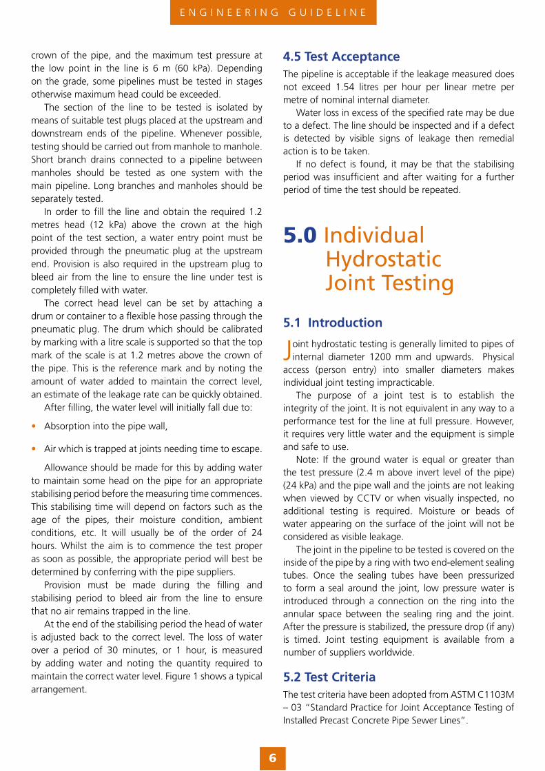
5.3 Precautions, Preparation and ProcedurePrecautions, preparations and procedures detailed in ASTM C1103M – 03 “Standard Practice for Joint Acceptance Testing of Installed Precast Concrete Pipe Sewer Lines” and those provided by the manufacturer of the joint test equipment should be followed, with all appropriate local health and safety practices implemented. Figure 2 shows a typical arrangement. Figure 3 shows typical equipment.
5.4 Test AcceptanceIf the pressure holds, or drops less than 0.7 m head (7 kPa) in 5 seconds, the joint is acceptable. Practically, the test is a go/no go test. If the joint being tested fails, it shall be retested, or repaired if necessary and retested in accordance with this practice.
7
PERFORMANCE TESTING OF INSTALLED NON-PRESSURE RUBBER RING JOINTED CONCRETE STORMWATER PIPELINES
Figure 2. Joint Test
Figure 3. Typical Hydrostatic Joint Testing equipment: Source Cherne Catalogue 2017

6.0 Air Testing Non-Pressure Pipelines
6.1 Introduction
Air testing of non-pressure concrete Stormwater pipelines is not considered appropriate in Australia
where there is typically no requirement to do so and different manufacturing practices prevail, including the provision of lifting holes in the pipe wall.
Performance testing of non – pressure concrete Stormwater pipelines is not necessary in most installations as the performance of the concrete pipe structure is tested during manufacture. (i.e. where manufacturer watertightness testing of pipes has been specified). However, to validate the workmanship and confirm that the pipeline has been installed correctly, an ‘installed performance test’ such as the air test can be applied.
The most reliable proof test of the workmanship in a laid concrete pipeline is by the application of a hydrostatic test, but it is not always convenient to carry this out and it may be possible to apply a low-pressure air test. However, concrete pipelines will tend to show greater and more variable permeability to air than to water, so care is needed in applying the air test and in interpreting results. Although results of air tests and water tests do
not always correlate, a satisfactory air test can serve as a useful indication that a line will pass a water test.
The procedure is not intended to be an unqualified endorsement of air testing which is not an accurate guide to performance under hydrostatic head, but is intended to standardise and avoid misapplication of the test. It can provide the criteria for acceptance of a pipeline but not for its rejection. The option to carry out a water test if the pipeline fails the air test must always be available to the installer. See Appendix A for the Air Testing procedure.
The CPAA procedure for the air test is based on a test pressure between 10 – 8 kPa. From experience, this pressure is less affected by temperature fluctuations allowing the pressure to stabilise whilst making the test safer to carry out.
6.2 Important Features of Air Testing Points to note in the application of air tests are as follows:
• Concrete pipes are more permeable to air than they are to water. For this reason, a failed air test shall not deem the pipeline unsatisfactory. If the pipeline fails the air test again a hydrostatic test should be carried out after a further 24 hours soakage.
• The basic air leakage is affected by the degree of dampness in the pipe walls. This is seen as one reason for the poor correlation of air test results with hydrostatic water test results. Therefore, the section of line to be tested should be rigorously flushed out
E N G I N E E R I N G G U I D E L I N E
8
Figure 4. Low Pressure Air Test

and cleaned. This serves to remove any debris and thoroughly wet the pipe surface. It is recommended that pipelines be water soaked for a period of 24 hours prior to the air testing.
• Care is needed in making air tight seals at the plugs, joints and the air test equipment of the pipework. It is recommended that pneumatic plugs are used instead of screw rubber plugs, as these provide a better seal at the pipe walls. Loss of air at plug points, often difficult to detect, can be wrongly interpreted as being due to faults in the pipeline.
• As pipe diameters increase the air test becomes more hazardous because of the danger of end seals (which can have imposed loads of several tonnes) blowing out.
• Defects may not be easy to locate with air tests.
• Experience with air tests in New Zealand indicates that concrete pipelines take a long time for pressure to stabilise as compared to pipelines of some other pipe materials. The omission of pressure stabilisation at commencement may yield incorrect results.
6.3 Test CriteriaThe minimum holding time required for pressure to drop from 10 to 8 kPa for the corresponding pipeline length and diameter, tested as detailed in Appendix B for each pipeline diameter and length.
6.4 Preparation and ProcedurePreparation and procedure is detailed in Appendix B
6.5 Test AcceptanceWhen tested as per Appendix B, the pipeline is considered acceptable if it holds pressure for a period exceeding that tabled in the Appendix.
Pipelines that fail to meet the test criteria could be tested at shorter segments to locate the possible defect, each segment that passes the test shall be considered adequate.
Pipelines that fail to meet this test criteria shall be tested using the hydrostatic method and accepted if the hydrostatic test passes.
6.6 Safety AspectsThe procedure for air testing larger diameter pipelines is hazardous because of the very large forces to be resisted by pneumatic plugs and the serious consequences of accidental bulkhead or plug blow out. The force on the plugs increases as the square of the socket diameter and the cost of maintaining safe working conditions increases rapidly with increasing pipe diameter. It is essential that appropriate pneumatic plugs and equipment are used to protect personnel involved in the testing from any harm.
9
PERFORMANCE TESTING OF INSTALLED NON-PRESSURE RUBBER RING JOINTED CONCRETE STORMWATER PIPELINES

Appendix A
Hydrostatic Test Procedure for Installed Non-Pressure Concrete Stormwater Pipelines
1. The section of line to be tested shall be flushed and cleaned.
2. The test may be applied to the completed pipeline or progressively to sections as laid. The test pressure at the high point of the line is to be 1.2 m (12 kPa) above the crown of the pipe and the maximum test pressure at the low point in the line is 6 m (60 kPa). Depending on the grade, some pipelines must be tested in stages otherwise maximum head could be exceeded.
3. Isolate the section of the line to be tested by means of suitable test plugs placed at the upstream and downstream ends of the pipeline. Whenever possible, testing should be carried out from manhole to man-hole. Short branch drains connected to a pipeline between manholes should be tested as one system with the main pipeline. Long branches and manholes should be separately tested.
4. All plugs must be firmly, safely and securely fitted. Care is needed in making water tight seals at all plugs. It is recommended that pneumatic plugs are used instead of screw rubber plugs as pneumatic plugs provide a much more effective seal at the pipe walls.
5. In order to fill the line and obtain the required 1.2 metres head (12 kPa) above the crown at the high point of the test section, a water entry point must be provided through the pneumatic plug at the upstream end. This requires a flexible hose be attached to this plug. Provision is also required in the upstream plug to bleed air from the line to ensure the line under test is completely filled with water.
6. The correct head level can be set by attaching a drum or container to the flexible hose. The drum which should be calibrated by marking with a litre scale is supported so that the top mark of the scale is at 1.2 metres above the crown of the pipe. This is the reference mark and by noting the amount of water added to maintain the correct level, an estimate of the leakage rate can be quickly obtained.
7. After filling, the water level will initially fall due to:
• Absorption into the pipe wall,
• Air which is trapped at joints needing time to escape.
Allowance should be made for this by adding water to maintain some head on the pipe for an appropriate stabilising period before the measuring time commences. This stabilising time will depend on factors such as the age of the pipes, their moisture condition, ambient conditions, etc. It will usually be of the order of 24 hours. Whilst the aim is to commence the test proper as soon as possible, the appropriate period will best be determined by conferring with the pipe suppliers.
8. Provision must be made during the filling and stabilising period to bleed air from the line to ensure that no air remains trapped in the line.
9. At the end of the stabilising period the head of water is adjusted back to the correct level. The loss of water over a period of 30 minutes, or 1 hour, is measured by adding water and noting the quantity required to maintain the correct water level.
10. The pipeline is acceptable if the leakage measured does not exceed 1.54 litres per hour per linear metre per metre of nominal internal diameter.
11. Water loss in excess of the specified rate may be due to a defect. The line should be inspected and if a defect is detected by visible signs of leakage then remedial action is to be taken. If no defect is found then it may be that the stabilising period was insufficient and after a further stabilising period the test should be repeated.
E N G I N E E R I N G G U I D E L I N E
10
Figure 5.

Appendix B
Air Tested Procedure for Installed Non-Pressure Concrete Stormwater Pipelines
1. The section of line to be tested shall be flushed and cleaned. This serves to clean out any debris and wet the pipe.
2. Isolate the section of the line to be tested by means of suitable test plugs. It is recommended that pneumatic plugs are used instead of screw rubber plugs as pneumatic plugs provide a much more effective seal at the pipe walls.
3. Care is needed in making air tight seals at plugs, joints and pipes of the air test equipment. Loss of air pressure at such points, often difficult to detect, can be wrongly interpreted as being due to faults in the pipeline.
4. One of the plugs should have an inlet valve for connection to a source of air under pressure.
5. Connect the air hose to the inlet tap and air compressor. The air equipment should consist of the necessary valves and pressure gauges to control the rate of air flowing into the test section, and to enable monitoring of the air pressure within the test section. The testing apparatus should be equipped with a safety valve to prevent the possibility of pressuring the test section to the capacity of the air compressor
6. All gauges used in the test shall be calibrated on a regular basis.
7. Add air slowly to the test section until the pressure is just over 10 kPa pressure. Regulate the air supply to maintain pressure between 10 & 11 kPa, whilst checking all plugs, and fittings, with soap solution to ensure there is no leakage. This period, which shall be a minimum of 15 minutes to allow the air temperature to stabilise with the pipe walls.
8. After the stabilisation period ensure the pressure is just above 10 kPa. Commence measuring time as the pressure falls to 10 kPa and note the time taken for it to drop a further 2 kPa to 8 kPa.
9. For the pipe to pass the test this time shall not be less than the holding time given in Table B1 appropriate to the diameter and length of line under test.
10. If the pipeline fails the test the cause of failure must be detected by visual or audible means and rectified and the test repeated. If the cause of failure cannot be detected the installer may either:
• Apply water to the line internally and/or externally and repeat the air test, or
• Apply the hydrostatic test to prove the pipeline is sound.
11
PERFORMANCE TESTING OF INSTALLED NON-PRESSURE RUBBER RING JOINTED CONCRETE STORMWATER PIPELINES
Table B1. AIR TEST MINIMUM HOLDING TIMES (MIN – SECS)
For an Average applied pressure of 9 kPa
10 20 30 40 50 60 70 80 90 100
225 0:11 0:22 0:33 0:44 0:55 1:06 1:17 1:28 1:38 1:41
300 0:19 0:39 0:58 1:18 1:37 1:57 2:14 2:14 2:14 2:14
375 0:31 1:01 1:31 2:02 2:32 2:50 2:50 2:50 3:12 3:33
450 0:44 1:28 2:11 2:55 3:22 3:22 3:22 4:06 4:36 5:07
525 1:00 1:59 2:59 3:55 3:55 4:11 4:53 5:34 6:16 6:58
600 1:18 2:35 3:53 4:29 4:29 5:28 6:22 7:17 8:11 9:06
Length of Test Section (Metres)Pipe ø(mm)
DISCLAIMERThe Concrete Pipe Association of Australasia believes the information giv-en within this brochure is the most up-to-date and correct on the subject. Beyond this statement, no guarantee is given nor is any responsibility as-sumed by the Association and its members.
Concrete Pipe Associationof Australasia
E N G I N E E R I N G G U I D E L I N E
Appendix C
Processes Adopted in the CPAA Review of Testing Procedures
2.1 Hydrostatic testsVarious hydrostatic test procedures are used in overseas countries with notable differences between them being the manner of application. These generally are carried out at maximum average test pressures ranging from 0.9 to 3.6 m head (9 to 35 kPa) and allowable water loss 0.5 to 1.54 l/hr/m diameter/m length.
On review, it was considered acceptable to align the CPAA test criteria with the ASTM C969M-02 allowable water leakage, adjusted to maintain the locally accepted minimum and maximum test heads of 1.2 m min to 6 m maximum (12 to 59 kPa). The acceptance criteria have been modified to an allowable leakage rate of 1.54 litres per hour per linear metre per metre of nominal internal diameter.
Hydrostatic watertightness testing of long lengths of installed pipe is not considered practical for pipes 1200 mm diameter and larger. For larger sizes designers and specifiers should consider hydrostatic pressure testing of individual joints, as detailed in ASTM 1103M-03.
2.2 Air TestingSafety aspects are a key consideration in any test procedure. The procedure for air testing larger diameter pipelines is hazardous because of the very large forces to be resisted by the plugs and the serious consequences of accidental blow out. The plug force increases as the square of the socket diameter and the cost of maintaining safe working conditions increases rapidly with increasing pipe diameter.
The literature review found that test pressures ranged from 3 – 30 kPa.
• A low pressure of 3 – 2.5 kPa is being used in NZ but is very sensitive to temperature changes and other variances in the pipeline.
• A pressure of 24 – 17 kPa was specified in ASTM C924 – 02 (2009). The Standard was withdrawn in 2013 due to the high pressures being a safety concern and replaced by ASTM C 1214 – 02 “Standard Test Method for Concrete Pipe Sewer Lines by Negative Air Pressure (Vacuum) Test Method” which uses the same acceptance criteria of the C924 – 02 test.
• A high pressure test of 30-27 kPa is also used in New Zealand and is specified for testing of flexible pipe in many NZ Codes of Practice.
The CPAA has previously recommended a pressure test between 10 – 8 kPa. From experience, this pressure
is less affected by temperature fluctuations allowing the pressure to stabilise whilst making the test safer to carry out. It was considered prudent to retain this test pressure. The CPAA holding times were previously derived using allowable air loss (pipe wall permeability) of 500 ml/minute/m2 based on a compromise rate of 1220 ml/minute/m2 which is midway between the ACPA figures for wet and dry pipe and adjusted to the lower average pressure values of the CPAA test. However, no maximum air loss values were adopted by the current CPAA criteria; based on the assumption that an air test will only be used for short runs of small diameter wastewater pipes.
For stormwater pipelines where various diameter pipelines are installed in short or long length runs between manholes, adopting pipe wall permeability as acceptance criteria for an air test made the test too sensitive in short lengths of small diameter pipelines where insignificant small defects cause failure. Conversely the test may fail to detect a significant defect in long lengths of large diameter pipelines. CPAA test acceptance criteria has addressed this by specifying upper and lower limits in its holding time calculations.
Holding times adopted for testing Stormwater lines were calculated based on the following air loss criteria:
• Minimum significant air loss rate of 24.8 l/min (corresponding to a small defect that allows water leaks from pipe in service) based on the ACPA value for wet pipes of 56.6 l/min.
• Concrete pipe wall permeability of 536 ml/minute/m2 (corresponding to a watertight concrete pipe wall).
• Maximum allowable air loss rate of 35.4 l/min (corresponding to a significant defect that might allow water leaks from pipe in service in a pipeline with very low permeability pipe walls).
A minimum holding time required for pressure to drop from 10 to 8 kPa for the corresponding pipeline length and diameter tested (as shown in Appendix B) was established for each pipeline diameter and length. Based on field experience the selected values will enable detection of any significant defect that may cause water exfiltration or infiltration of the pipeline in service. However, failure of a pipeline to meet this test criteria does not mean that the pipeline is prone to infiltration or exfiltration unless confirmed by a hydrostatic test.
The test criteria proposed are not intended to be an unqualified endorsement of air testing; which is not an accurate guide to performance under hydrostatic head, but is intended to standardise and avoid misapplication of the test. It can provide the criteria for acceptance of a pipeline but not for its rejection. The option to carry out a hydrostatic test, if the pipeline fails the air test, must always be available to the installer.