date: november 22, 2000 service bulletin no. 53 9a of crane-lear... · date: november 22, 2000...
TRANSCRIPT

DATE: November 22, 2000 Service Bulletin No. 539A (Supersedes Service Bulletin No. 539 and Supplement No. 1)
Engineering Aspects are FAA Approved
SUBJECT: Reprint of Crane/Lear Romec Service Bulletins No. RG9080-73-001, No. RG9570-73-001, and No. RG17980-73-001.
MODELS AFFECTED: Those Textron Lycoming aircraft engines shipped before December 11, 1999, that employ
Crane/Lear Romec rotary fuel pump models identified below. Lear Romec Bulletin Lear Romec P/N Lycoming P/N
RG-9080-73-001 RG9080F2 68262, 68262-85
RG9080J4A* LW-13909*, LW-13909-85* RG9080J6A LW-14444, LW-14444-85 RG9080J7A LW-13920, LW-13920-85 RG9080J8A* LW-15740, LW-15740-85* RG9570-73-001 RG9570K1 62E22288 RG9570P/P1 LW-19012 RG17980-73-001 RG17980 74547, 74547-85 RG17980A 76188, 76188-85 RG17980D 76486, 76486-85 RG17980E 77443, 77443-85 RG17980J 78993, 78993-85 RG17980K LW-11166, LW-11166-85 RG17980P LW-12534, LW-12534-85 RG17980U 62D21153, 62D21153-85
Crane/Lear Romec Service Bulletins No. RG9080-73-001, No. RG9570-73-001, and No. RG17980-73-001 list eligible Textron Lycoming engine model numbers for each affected fuel pump.*
TIME OF COMPLIANCE: Same as that required for Crane/Lear Romec Service Bulletins No. RG9080- 73-001, No. RG9570-
73-001, and No. RG17980-73-001. Crane/Lear Romec Service Bulletins No. RG9080-73-001, No. RG9570-73-001, and No. RG17980-73-001 are reprinted in their entirety as follows. Textron Lycoming requires compliance with these Service Bulletins.
These reprints are current at the time Textron Lycoming Service Bulletin No. 539A is issued. However, when complying with this Service Bulletin, insure that the reprints of Crane/Lear Romec Service Bulletins No. RG9080 73-001, No. RG9570-73-001, and RG17980-73-001 are still current at time of compliance.
Compliance with Textron Lycoming Service Bulletin No. 539A and Crane/Lear Romec Service Bulletins No. RG9080-73-001, No. RG9570-73-001, or RG17980-73-001 relieves required compliance with the latest issue of Textron Lycoming Service Bulletin No. 529 and Lear Romec Service Bulletin No. 101SB020.
* In addition to the engines listed in Crane/Lear Romec Service Bulletin No. RG9080-73-001, the TIO-540-AE2A engine, the TIO-540-AH1A engine and the TIO-540-AJ1A engine are eligible and subject to the bulletin.
Page 1 of 23
© 2000 by Textron Lycoming “All Rights Reserved

Service Bulletin No. 539A
NOTES
Pumps with a “/M” suffix after the Crane/Lear Romec Part Number have been modified to the configuration of the new Textron Lycoming Part Number and are not subject to Service Bulletin No. 529. Engines shipped from the factory after December 11, 1999 are equipped with the new Textron Lycoming Part Number fuel pump and are not subject to Service Bulletin No. 529. New Textron Lycoming part numbers that are not affected by this Service Bulletin are Nos. 62E22580, 62E22581, 62E22582, 62E22583, 62E22584, 62E22585, 62E22586, 62D22565, 62D22566, 62D22567, 62D22568, 62D22569, 62D22570, 62D22572, and 62D22573.
If the aircraft installation necessitates the removal of the fuel pump for compliance, it is recommended that Texaco Molytex EPO or an equivalent lubricant be applied to the drive spline before reassembly of the pump to the engine.
WARRANTY: For engines in warranty, comply with normal Textron Lycoming warranty application procedures. NOTE: Revision “A” to this Service Bulletin incorporates Supplement No. 1 and adds engine models TIO-540-AJ1A and
TIO-540-AH1A. Page 2 of 23

LEAR ROMEC
SERVICE BULLETIN FUEL PUMP-Replacement of valve housing and related seals.
1. Planning Information.
A. Effectivity.
NOTE: This Service Bulletin provides an alternate means of compliance with Service Bulletin 101SB020.
This bulletin applies to the following Lear Romec rotary fuel pump models: Eligibility GO-435; GO-435-C2; GO-435-C2A; GO-435-C2A2; GO-435-C2B; GO-435-C2B1; GO-435-C2B2; GO-435-C2C GO-435-C2D; GO-435-C2E; GO-435-D1; GO-480; GO-480-A1A; GO-480-B; GO-480-B1; GO-480-B1A6; GO-480-B1D; GO-480-C1D6; GO-480-C2C6; GO-480-C2D6; GO-480-C2E6; GO-480-C3A6; GO-480-E1A6; GO-480-F6; GO-480-F1A6; GO-480-F2A6; GO-480-F2D6; GO-480-F3A6; GO-480-F3B6; GO-480-F4A6; GO-480-F4B6; GO-480-G1A6; GO-480-G1D6; GO-480-G1H6; GO-480-G1J6; GO-480-G2D6; GO-480-G2F6
IO-540-K1E5:IO-720-A1A: IO-720-A1B; IO-720-B1B; IO-720-C1B; IO-720-D1B; LTIO-540-F2BD: LTIO-540-J2BD TIGO-541-D1A: TIGO-541-D1B; TIGO-541-EIA; TIO-360-A3B6; TIO-540-A1A; TIO-540-A1B; TIO-540-A2A TIO-540-A2B; TIO-540-A2C; TIO-540-J2B; TIO-540-U2A
TIO-540-AB1AD: TIO-540-AA1AD; LTIO-540-U2A; LTIO-540-J2B
IO-540-K1F5D; LTIO-540-W2A; TIO-540-F2BD; TIO-540-J2BD; TIO-540-N2BD; TIO-540-R2AD; TIO-540-T2AD; TIO-540-V2AD
IO-720-A1B; LTIO-540-V2AD; TiO-540-W2A
B. Reason.
To introduce pump design enhancements that provide improved relief valve housing sealing characteristics.
C. Description.
This Service Bulletin provides modification instructions to incorporate new valve housings and associated parts to provide enhanced resistance to fuel leakage.
Page 1 of 7
Nov 29/99 Page 3 of 23
Service Bulletin No. 539A
Lear Romec P/N RG9080F2
TC Holder P/N's Lycoming 68262 68262-85
RG9080J4A
RG9080J6A
RG9080J7A
RG9080J8A
Lycoming LW-13909 LW-13909-85
Lycoming LW-14444 LW-14444-85 Lycoming LW-13920 LW-13920-85 Lycoming LW-15740 LW-15740-85
RG9080-73-001

LEAR ROMEC
SERVICE BULLETIN FUEL PUMP - Replacement of valve housing and related seals.
D. Compliance. The manufacturer recommends implementation of this bulletin at the next overhaul, earlier at owner's discretion.
E. Approval.
This Service Bulletin has been reviewed by Lycoming and the FAA. The repairs and modifications herein comply with FAR Part 25 and are recorded at the supplier as FAA approved for installation on the engine models cited in paragraph 1 .A.
F. Manpower,
Approximately 3 man-hours and one person are necessary to do the modification of one pump.
G. Material.
Material required to accomplish the Service Bulletin is available for shipment from the pump manufacturer. See paragraph 3.A .for listing of parts.
H. Tooling-Price and Availability.
Only standard tools are required to accomplish this bulletin.
I. Weight and Balance.
Not applicable.
J. References.
(1) RG9080 Series dated Fob 07/85 with Rev 3 dated Jan 06/95
2. Accomplishment Instructions.
NOTE: The following modification shall be performed at an accessory repair station which is fully equipped and certified by the FAA to perform fuel accessory repair and modification.
A. Disassemble the Regulator Valve. See figure 1.
(1) Cut and remove all safety wire from fasteners,
(2) Remove screws and washers (items 2 and 3, figure 1 ).
(3) Separate the regulator valve components (items 4 thru 22) as shown in figure 1.
Page2of7
RG9080-73-001 Nov29/99
Service Bulletin No. 539A
Page 4 of 23

LEAR ROMEC
SERVICE BULLETIN FUEL PUMP -Replacement of valve housing and related seals.
NOTE: ITEM NUMBERS ARE THE SAME AS THOSE USED IN THE CMM
Regulator Valve Assembly Before Modification Figure 1
Page 3 of 7 RG9080-73-001 Nov 29/99
Page 5 of 23
Service Bulletin No. 539A

LEAR ROMEC
SERVICE BULLETIN FUEL PUMP - Replacement of valve housing and related seals.
(4) Discard the following parts:
(a) Four (4) each screws (item 2, figure 1).
(b) Four (4) each washers (item 3, figure 1 ).
(c) One (1) each gasket (item 22, figure 1 ).
(d) One (1) each valve housing assembly (consisting of parts items 19 thru 21 .figure 1).
(e) Two (2) each diaphragms (item 15, figure 1 ).
(5) Remove nut (item 5, figure 1) and withdraw the adjusting screw assembly (item 7, figure 1) from the valve cover (item 11, figure 1 ). Remove and discard packing with retainer (item 6, figure 1 ).
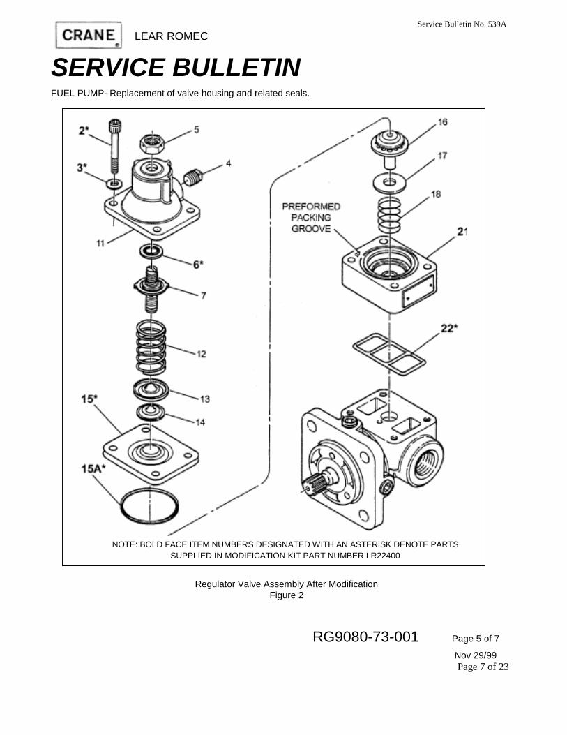
B. Reassemble the Regulator Valve. See figure2.
(1) Lubricate the packing (o-ring) portion of the packing with retainer (item 6, figure 2) with petrolatum (petroleum jelly) and install it over the screw slot end of the adjusting screw assembly (item 7, figure 2) and up against the screw flange. Exercise care that screw threads do not nick or cut the packing (o-ring).
(2) Insert the adjusting screw assembly (item 7, figure 2) through the valve cover (item 11, figure 2) and thread on the locknut (item 5, figure 2). Valve adjustment will be made at test.
(3) Lubricate the ladder seal (item 22, figure 2) with petrolatum (petroleum jelly) and install it in the groove cut in the surface of the valve housing (item 21, figure 2) that mates with the pump housing.
NOTE: Make certain ladder seal is completely seated in groove prior to assembly.
(4) Lubricate preformed packing (o-ring) (item 15A, figure 2) with petrolatum (petroleum jelly) and install it in the groove cut into the top of the valve housing assembly (item 21, figure 2).
(5) Complete assembly according to the applicable component maintenance manual and secure the valve housing (item 11, figure 2) using screws (item 2, figure 2) and washers (item 3, figure 2). Tighten screws evenly and progressively in a crisscross pattern to 23-25 inch-pounds torque in the sequence shown in figure 3.
CAUTION: SEAT THE COVER BY DRAWING DOWN THE SCREWS IN GRADUAL INCREMENTS, FOLLOWING A PROGRESSIVE CRISSCROSS PATTERN AS ILLUSTRATED IN FIGURE 3, UNTIL THE COVER IS FIRMLY SEATED. DRAW DOWN THE SCREWS EVENLY. DO NOT TIGHTEN SCREWS TO FINAL TORQUE DURING THE FIRST DRAW DOWN; UNEVEN TENSION CAN CAUSE DISTORTION OR OVERSTRESSING OF PARTS. COMPLETE THE PROCEDURE BYTIGHTENING EACH SCREW GRADUALLY TO THE SPECIFIED TORQUE VALUE. DO NOT EXCEED THE MAXIMUM TORQUE SPECIFIED.
Page4 of 7 Page 6 of 23 RG9080-73-001 Nov29 /99
Service Bulletin No. 539A
LEAR ROMEC
SERVICE BULLETIN FUEL PUMP- Replacement of valve housing and related seals.
NOTE: BOLD FACE ITEM NUMBERS DESIGNATED WITH AN ASTERISK DENOTE PARTS SUPPLIED IN MODIFICATION KIT PART NUMBER LR22400
Regulator Valve Assembly After Modification Figure 2
RG9080-73-001 Page 5 of 7
Nov 29/99 Page 7 of 23
Service Bulletin No. 539A

LEAR ROMEC
SERVICE BULLETIN FUEL PUMP - Replacement of valve housing and related seals.
Torquing Sequence- RG9080 Series Figure 3
C. Test.
(1) Test the pump and set the pressure regulating valve according to the applicable component maintenance manual.
(2) Upon successful completion of testing, retorque valve housing screws (item 2, figure 2) to 23-25 inch-pounds torque.
(3) Safety-wire regulator valve and valve cover screws (item 2, figure 2) according to applicable component maintenance manual.
Page 6 of 7
Nov29/99
Service Bulletin No. 539A
Page 8 of 23 RG9080-73-001

LEAR ROMEC
SERVICE BULLETIN FUEL PUMP-Replacement of valve housing and related seals.
2. Material Information.
A. Material Requirements
The following material is required, per engine, to accomplish this Service Bulletin and for spare part provisioning:
NOTE: Price information is available from Lear Romec PH: 440-284-5411 or 440-284-5460; FX: 440-284-0221.
' Includes (1 ea) valve housing LR47007, (1 ea) rotation information plate RA9099 and (2 ea)drive screws RD55101 . 4. Re-identification
Using metal stamp or vibropeen, identify pumps modified according to this bulletin by adding the suffix /M to the unit part number on the identification plate.
Page 7 of 7
Nov 29/99 Page 9 of 23
Service Bulletin No. 539A
RG9080-73-001

Service Bulletin No. 539A
LEAR ROMEC
SERVICE BULLETIN FUEL PUMP - Replacement of valve housing and related seals.
1. Planning Information.
A. Effectivity.
NOTE: This Service Bulletin provides an alternate means of compliance with Service Bulletin 101SB020.
This bulletin applies to the following Lear Romec rotary fuel pump models:
Lear Romec P/N TC Holder P/N's Eligibility
RG9570K1 Lycoming 62E22288 AEIO-540-D4D5 RG9570P/P1 Lycoming LW-19012 TIO-540-S1AD
B. Reason.
To introduce pump design enhancements that provide improved relief valve housing sealing characteristics.
C. Description.
This Service Bulletin provides modification instructions to incorporate new valve housings and associated parts to provide enhanced resistance to fuel leakage.
D. Compliance.
The manufacturer recommends implementation of this bulletin at the next overhaul, earlier at owner's discretion.
E. Approval. This Service Bulletin has been reviewed by Lycoming and the FAA. The repairs and modifications herein comply with FAR Part 25 and are recorded at the supplier as FAA approved for installation on the engine models cited in paragraph 1 .A.
F. Manpower.
Approximately 3 man-hours and one person are necessary to do the modification of one pump.
G. Material.
Material required to accomplish the Service Bulletin is available for shipment from the pump manufacturer. See paragraph 3.A. for listing of parts.
H. Tooling-Price and Availability.
Only standard tools are required to accomplish this bulletin.
Page 10 of 23 RG9570-73-001 Page 1 of 7
Nov 29/99

LEAR ROMEC
SERVICE BULLETIN FUEL PUMP - Replacement of valve housing and related seals.
I. Weight and Balance.
Not applicable.
J. References.
(1 ) RG9570K/J/P Series dated Mar 15/86 with Rev 1 dated Nov 22/91
2. Accomplishment Instructions. NOTE: The following modification shall be performed at an accessory repair station which is fully equipped and
certified by the PAA to perform fuel accessory repair and modification.
A. Disassemble the Regulator Valve. See figure 1.
(1) Cut and remove all safety wire from fasteners.
(2) Remove screws and washers (items 2 and 3, figure 1 ).
(3) Separate the regulator valve components (items 4 thru 22) as shown in figure 1.
(4) Discard the following parts:
(a) Four (4) each screws (item 2, figure 1 ).
(b) Four (4) each washers (item 3, figure 1 ).
(c) One (1 ) each gasket (item 22, figure 1 ).
(d) One (1 ) each valve housing assembly (consisting of parts items 19 thru 21, figure 1 ).
(e) Two (2) each diaphragms (item 15, figure 1 ).
(5) Remove nut (item 5, figure 1 ) and withdraw the adjusting screw assembly (item 7, figure 1 ) from the valve cover (item 11, figure 1 ). Remove and discard packing with retainer (item 6, figure 1 ).
Page 2 of 7 RG9570-73-001 Nov 29/99
Page 11 of 23
Service Bulletin No. 539A

LEAR ROMEC
SERVICE BULLETIN FUEL PUMP - Replacement of valve housing and related seals.
NOTE: ITEM NUMBERS ARE THE SAME AS THOSE USED IN THE CMM
Regulator Valve Assembly Before Modification Figure 1
Page 3 of 7 Nov 29/99
Page 12 of 23
Service Bulletin No. 539A
RG9570-73-001
Service Bulletin No. 539A
CRANE LEAR ROMEC
SERVICE BULLETIN FUEL PUMP - Replacement of valve housing and related seals.
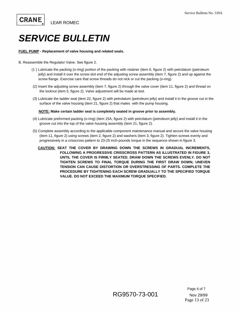
B. Reassemble the Regulator Valve. See figure 2.
(1 ) Lubricate the packing (o-ring) portion of the packing with retainer (item 6, figure 2) with petrolatum (petroleum jelly) and install it over the screw slot end of the adjusting screw assembly (item 7, figure 2) and up against the screw flange. Exercise care that screw threads do not nick or cut the packing (o-ring).
(2) Insert the adjusting screw assembly (item 7, figure 2) through the valve cover (item 11, figure 2) and thread on the locknut (item 5, figure 2). Valve adjustment will be made at test.
(3) Lubricate the ladder seal (item 22, figure 2) with petrolatum (petroleum jelly) and install it in the groove cut in the surface of the valve housing (item 21, figure 2) that mates with the pump housing.
NOTE: Make certain ladder seal is completely seated in groove prior to assembly.
(4) Lubricate preformed packing (o-ring) (item 15A, figure 2) with petrolatum (petroleum jelly) and install it in the groove cut into the top of the valve housing assembly (item 21, figure 2).
(5) Complete assembly according to the applicable component maintenance manual and secure the valve housing (item 11, figure 2) using screws (item 2, figure 2) and washers (item 3, figure 2). Tighten screws evenly and progressively in a crisscross pattern to 23-25 inch-pounds torque in the sequence shown in figure 3.
CAUTION: SEAT THE COVER BY DRAWING DOWN THE SCREWS IN GRADUAL INCREMENTS, FOLLOWING A PROGRESSIVE CRISSCROSS PATTERN AS ILLUSTRATED IN FIGURE 3, UNTIL THE COVER IS FIRMLY SEATED. DRAW DOWN THE SCREWS EVENLY. DO NOT TIGHTEN SCREWS TO FINAL TORQUE DURING THE FIRST DRAW DOWN; UNEVEN TENSION CAN CAUSE DISTORTION OR OVERSTRESSING OF PARTS. COMPLETE THE PROCEDURE BY TIGHTENING EACH SCREW GRADUALLY TO THE SPECIFIED TORQUE VALUE. DO NOT EXCEED THE MAXIMUM TORQUE SPECIFIED.
Page 4 of 7
RG9570-73-001 Nov 29/99 Page 13 of 23

Service Bulletin No. 539A
LEAR ROMEC
SERVICE BULLETIN FUEL PUMP - Replacement of valve housing and related seals.
NOTE: BOLD FACE ITEM NUMBERS DESIGNATED WITH AN ASTERISK DENOTE
PARTS SUPPLIED IN MODIFICATION KIT PART NUMBER LR22400
Regulator Valve Assembly After Modification Figure 2
Page 5 of 7
Nov 29/99 Page 14 of 23
RG9570-73-001

Service Bulletin No. 53 9A LEAR ROMEC
SERVICE BULLETIN FUEL PUMP - Replacement of valve housing and related seals.
TIGHTEN SCREWS EVENLY VIEW B AND PROGRESSIVELY IN THE NUMBERED SEQUENCE SHOWN
Torquing Sequence-RG9570 Series
Figure 3 C. Test.
(1) Test the pump and set the pressure regulating valve according to the applicable component maintenance manual.
(2) Upon successful completion of testing, retorque valve housing screws (item 2, figure 2) to 23-25 inch-pounds torque.
(3) Safety-wire regulator valve and valve cover screws (item 2, figure 2) according to applicable component maintenance manual.
Page 6 of 7 Nov 29/99
Page 15 of 23 RG9570-73-001

Service Bulletin No. 539A
CRANE LEAR ROMEC
SERVICE BULLETIN FUEL PUMP - Replacement of valve housing and related seals. 3.
Material Information. A. Material Requirements
The following material is required, per engine, to accomplish this Service Bulletin and for spare part provisioning:
NOTE: Price information is available from Lear Romec PH: 440-284-5411 or 440-284-5460; FX: 440-284-0221.
' Includes (1 ea) valve housing LR47007, (1 ea) rotation information plate RA9099 and (2 ea) drive screws RD55101.
3. Re-identification Using metal stamp or vibropeen, identify pumps modified according to this bulletin by adding the suffix /M
Page 7 of 7
Nov 29/99 Page 16 of 23
RG9570-73-001

LEAR ROMEC
SERVICE BULLETIN FUEL PUMP- Replacement of valve housing and related seals.
1. Planning Information.
A. Effectivity. NOTE: This Service Bulletin provides an alternate means of compliance with Service Bulletin 101SB020.
This bulletin applies to the following Lear Romec rotary fuel pump models:
Lear Romec P/N TC Holder P/N's EligibilityIO-540-GIB5; IO-540-GID5; IO540-J4A5; IO-540-K1A5: IO-540-R1A5; IO-720-A1A; IO-720-A1B IO-720-A1A; IO-720-A1B IO-320-C1A: IO-320-F1A: IO-540-G 1 C5; IO-540-K1 A5; IO-540-K1B5; IO-540-K1F5 IO-360-A1B; TIO-360-A1B IO-360-B1D; IO-540-G 1B5; IO-540-G1D5; IO-540-A15; IO-540-K1C5; IO-540-K1D5; IO-540-K1 F5; IO-540-LIA5; IO-540-P1A5; IO-540-A1A5; TIO-540-A2B; TIO-540-C1A; TIO-540-E1A; TIO-540-G1A; TIO-540-H1A 10-540-K1 A5D; LIO-320-C1A; TIO-360-C1A6D IO-540-M2A5D; TIO-540-AA1AD; TIO-540-AB1AD TIO-540-AF1A; TIO-540-AF1B
B. Reason.
To introduce pump design enhancements that provide improved relief valve housing sealing characteristics.
C. Description.
This Service Bulletin provides modification instructions to incorporate new valve housings and associated parts to provide enhanced resistance to fuel leakage.
D. Compliance.
The manufacturer recommends implementation of this bulletin at the next overhaul, earlier at owner's discretion.
Page 1 of 7
Nov 29/99 Page 17 of 23
Service Bulletin No. 539A
RG 17980
RG17980A RG17980D
RG17980E RG17980J
Lycoming 74547, 74547-85
Lycoming 76188, 76188-85 Lycoming 76486, 76486-85
Lycoming Lycoming
77443, 77443-85 78993, 78993-85
Lycoming LW-11166, LW-11166-85
Lycoming LW-12534, LW-12534-85
Lycoming 62D21153, 62D21153-85
RG17980K
RG17980P
RG17980U
RG17980-73-001

LEAR ROMEC Service Bulletin No.539A
SERVICE BULLETIN FUEL PUMP- Replacement of valve housing and related seals.
E. Approval.
This service bulletin has been reviewed by Lycoming and the FAA. The repairs and modifications herein comply with FAR Part 25 and are recorded at the supplier as FAA approved for installation on the engine models cited in paragraph 1 .A.
F. Manpower.
Approximately 3 man-hours and one person are necessary to do the modification of one pump.
G. Material.
Material required to accomplish the Service Bulletin is available for shipment from the pump manufacturer. See paragraph 3.A. for listing of parts.
H. Tooling-Price and Availability.
Only standard tools are required to accomplish this bulletin.
I. Weight and Balance.
Not applicable.
J. References.
(1) RG 17980 Series dated Sep 17/86 with Rev 3 dated Sep 18/91.
(2) Accomplishment Instructions.
NOTE: The following modification shall be performed at an accessory repair station which is fully equipped and certified by the FAA to perform fuel accessory repair and modification.
A. Disassemble the Regulator Valve. See figure 1. (1) Cut and remove all safety wire from fasteners.
(2) Remove screws and washers (15 and 20, figure 1 ).
(3) Separate the regulator valve components (5 thru 90) as shown in figure 1. (a) Remove valve cover assembly (item 25, Figure 1) (if necessary rap cover with a plastic hammer to break the seal).
(b) Retrieve ball (item 35, figure 1 ) and spring (item 40, figure 1 ).
(c) Remove safety relief valve assembly (item 45, figure 1 ) from valve housing (item 85, figure 1 ).
(d) Tap off valve housing (item 85, Figure 1) with a plastic hammer. Remove and retain identification plate (item 50, figure 1 ). Peel off gasket (item 90, figure 1) (if necessary remove any clinging gasket material with a non-metalic scraper).
(e) Insert a suitable wire booking device into the hole located in the center of the bypass valve guide (item 70, figure 1 ) and withdraw the guide. Tilt valve housing and drop out the spring (item 75, figure 1 ) and bypass valve (item 80, figure 1 ).
Page 2 of 7 RG17980-73-001 Nov 29/99
Page 18 of 23

LEAR ROMEC
SERVICE BULLETIN FUEL PUMP - Replacement of valve housing and related seals.
30
Regulator Valve Assembly Before Modification Figure 1
RG17980-73-001 Page 3 of 7
Nov 29/99 Page 19 of 23
Service Bulletin No. 539A

LEAR ROMEC
Service Bulletin No. 539A
SERVICE BULLETIN FUEL PUMP - Replacement of valve housing and related seals.
(4) Discard the following parts:
(a) Four (4) each screws (item 15, figure 1 ).
(b) Four (4) each washers (item 20, figure 1 )
(c) One (1 ) each gasket (item 90, figure 1 ).
(d) One (1 ) each valve housing assembly (consisting of items 55, 60, 65 & 85 figure 1 ). Remove and retain identification plate for installation on new valve housing assembly (item 50, figure 1 ).
(d) One (1) each relief valve assembly (item 45, figure 1)
B. Reassemble the Regulator Valve. See figure2.
(1) Bypass Valve. Install bypass valve (item 80, figure 2), bypass valve spring (item 75, figure 2) and bypass valve guide (item 70, figure 2) in valve housing (item 85, Figure 2). Bend prongs of bypass valve guide (item 70, figure 2) so that they fit snugly in valve port.
(2) Lubricate the seal (item 90, figure 2) with petrolatum (petroleum jelly) and install it in the groove cut in the surface of the valve housing (item 85, figure 2) that mates with the pump housing.
NOTE: Make certain seal is completely seated in groove prior to assembly.
(3) Lubricate preformed packing (o-ring) (item 45A, figure 2) with petrolatum (petroleum jelly) and install it in the groove cut into the top of the valve housing assembly (item 85, figure 2).
(4) Complete assembly according to the applicable component maintenance manual and secure the valve housing (item 25, figure 2) using screws (item 15, figure 2) and washers (item 20, figure 2). Tighten screws evenly and progressively in a crisscross pattern to 23-25 inch-pounds torque in the sequence shown in figure 3.
CAUTION: SEAT THE COVER BY DRAWING DOWN THE SCREWS IN GRADUAL INCREMENTS, FOLLOWING A PROGRESSIVE CRISSCROSS PATTERN AS ILLUSTRATED IN FIGURE 3, UNTIL THE COVER IS FIRMLY SEATED. DRAW DOWN THE SCREWS EVENLY. DO NOT TIGHTEN SCREWS TO FINAL TORQUE DURING THE FIRST DRAW DOWN; UNEVEN TENSION CAN CAUSE DISTORTION OR OVERSTRESSING OF PARTS. COMPLETETHE PROCEDURE BY TIGHTENING EACH SCREW GRADUALLY TO THE SPECIFIED TORQUE VALUE. DO NOT EXCEED THE MAXIMUM TORQUE SPECIFIED.
RG17980-73-001 Page 4 of 7
Nov 29/99 Page 20 of 23

CRA LEAR ROMEC
SERVICE BULLETIN FUEL PUMP- Replacement of valve housing and related seals.
Regulator Valve Assembly After Modification Figure 2
RG17980-73-001 Page 5 of 7
Nov 29/99 Page 21 of 23
Service Bulletin No. 539A
30 \

LEAR ROMEC
SERVICE BULLETIN
FUEL PUMP - Replacement of valve housing and related seals.
VIEW A
TIGHTEN SCREWS EVENLY AND PROGRESSIVELY IN THE NUMBERED SEQUENCE SHOWN
Torquing Sequence - RG17980 Series Figure 3
C. Test.
(1 ) Test the pump and set the pressure regulating valve according to the applicable component maintenance manual.
(2) Upon successful completion of testing, retorque valve housing screws (item 15, figure 2) to 23-25 inch-pounds torque.
(3) Safety-wire regulator valve and valve cover screws (items 30 & 15, figure 2) according to applicable component maintenance manual.
Page 6 of 7
Nov 29/99
Service Bulletin No. 539A
Page 22 of 23 RG17980-73-001

LEAR ROMEC
SERVICE BULLETIN FUEL PUMP - Replacement of valve housing and related seals. 3.
3. Material Information.
A. Material Requirements
The following material is required, per engine, to accomplish this Service Bulletin and for spare part provisioning:
NOTE: Price information is available from Lear Romec PH: 440-284-5411 or 440-284-5460; FX: 440-284-0221.
' Includes (1 ea) valve housing LR47102, (1 ea) rotation information plate RA9099 and (2 ea)drive screws RD55101 . 4. Re-identification
Using metal stamp, identify pumps modified according to this bulletin by adding the suffix /M to the unit part number on the identification plate (item 50, figurel ) and attach to valve housing (item 85, figure 2) using two (2) drive screws (item 55, figure 2).
Page 7 of 7
Nov 29/99 Page 23 of 23
Service Bulletin No. 539A
RG17980-73-001