datenblatt db en psr-mc50 - rs components type order no. pcs. / pkt. safety relay for monitoring...
TRANSCRIPT

1 Description
IEC 62061
SILCL
Safety relays for monitoring non-equivalent signal
generators
PSR-MC50
© PHOENIX CONTACT
Data sheet
Intended Use
The PSR-MC50 safety relay can be used to monitor two-
channel non-equivalent signal generators, e.g., magnetic
switches, as well as to control actuators.
The safety relay is equipped with three enabling current
paths that drop out without delay corresponding to stop cat-
egory 0 according to EN 60204-1.
The enabling current paths are controlled as an automatic or
manual, monitored start once sensor circuit channel 1 has
been closed and channel 2 has been opened.
With the manual, monitored reset device, a machine start
may not be triggered in accordance with EN ISO 13849-1.
Features
– Safety relays for monitoring non-equivalent signal gen-
erators, e.g., magnetic switches
– Suitable up to category 4, PL e (EN ISO 13849-1),
SILCL 3 (EN 62061)
– 1 two-channel non-equivalent sensor circuit
– 3 undelayed enabling current paths
– 1 digital signal output
– Option of screw or spring-cage terminal blocks for plug-
in
– 12.5 mm housing width
WARNING: Risk of electric shock
Observe the safety instructions in the corresponding section!
Make sure you always use the latest documentation.
It can be downloaded from the product at phoenixcontact.net/products.
This data sheet meets the same requirements as the original operating instructions in terms of contents and is
valid for all products listed on the following pages.
106176_en_01 2015-05-19

PSR-MC50
106176_en_01 PHOENIX CONTACT 2
2 Table of contents
1 Description .............................................................................................................................. 1
2 Table of contents ..................................................................................................................... 2
3 Ordering data .......................................................................................................................... 3
4 Technical data ......................................................................................................................... 3
5 Safety notes............................................................................................................................. 6
6 Basic circuit diagram ............................................................................................................... 7
7 Derating................................................................................................................................... 7
7.1 Vertical or horizontal mounting position ..................................................................................... 7
8 Load curve............................................................................................................................... 7
8.1 Ohmic load ........................................................................................................................ 7
9 Function/time diagrams ........................................................................................................... 8
9.1 Time diagram for automatic start ............................................................................................. 8
9.2 Time diagram for manual, monitored start .................................................................................. 8
10 Operating and indication elements .......................................................................................... 9
10.1 Connection versions............................................................................................................. 9
10.2 Connection assignment......................................................................................................... 9
11 Mounting and connection ...................................................................................................... 10
12 Startup................................................................................................................................... 10
13 Calculating the power dissipation .......................................................................................... 11
14 Diagnostics............................................................................................................................ 12
14.1 General states .................................................................................................................. 12
14.2 Error Messages................................................................................................................. 12
15 Application examples ............................................................................................................ 14
15.1 Magnetic switch monitoring/automatic start .............................................................................. 14
15.2 Magnetic switch monitoring/manual, monitored start................................................................... 14
15.3 Safety door monitoring/automatic start .................................................................................... 15
15.4 Safety door monitoring/manual, monitored start......................................................................... 15
16 Revision history ..................................................................................................................... 16

PSR-MC50
106176_en_01 PHOENIX CONTACT 3
Description Type Order No. Pcs. / Pkt.
Safety relay for monitoring non-equivalent signal generators up to SIL 3,
SILCL 3, Cat. 4, PL e, 2-channel, non-equivalent operation, automatic or
manual, monitored start, 3 enabling current paths, US = 24 V DC, plug-in
screw terminal block
PSR-MC50-3NO-1DO-24DC-SC 2700553 1
Safety relay for monitoring non-equivalent signal generators up to SIL 3,
SILCL 3, Cat. 4, PL e, 2-channel, non-equivalent operation, automatic or
manual, monitored start, 3 enabling current paths, US = 24 V DC, plug-in
spring-cage terminal block
PSR-MC50-3NO-1DO-24DC-SP 2700564 1
3 Ordering data
4 Technical data
Hardware/firmware version
HW/FW ≥ 00/-- (The technical data and safety characteristics are valid as of the specified
HW/FW version.)
Input data
Rated control supply voltage US 24 V DC -15 % / +10 %
Rated control supply current IS typ. 80 mA
Typical inrush current 5 A (t = 200 s at Us)
< 20 mA (with Us/Ix to S12)
< 200 mA (with Us/Ix to S34)
< 5 mA (with Us/Ix to S13)
Current consumption < 5 mA (with Us/Ix to S12)
< 5 mA (with Us/Ix to S13)
> -5 mA (with Us/Ix to S34)
< 10 mA (with Us/Ix to S34)
Power consumption at US typ. 1.92 W
Voltage at input/start and feedback circuit 24 V DC -15 % / +10 %
Filter time 1 ms (at A1 in the event of voltage dips at Us)
max. 1.5 ms (at S12, S13; test pulse width)
min. 7.5 ms (at S12, S13; test pulse rate)
Test pulse rate = 5 x Test pulse width
Max. permissible overall conductor resistance
(Input and reset circuit at US)
150 Ω
Typical response time at Us < 175 ms (automatic start)
< 175 ms (manual, monitored start)
Typical starting time with Us < 250 ms (when controlled via A1)
Typical release time with Us < 20 ms (when controlled via A1 or S12 and S13.)
Recovery time < 500 ms
Maximum switching frequency 0.5 Hz
Operating voltage display 1 x green LED
Status display 3 x green LED
Protective circuit Surge protection Suppressor diode
Reverse polarity protection for rated control supply voltage
Output data
Contact type 3 enabling current paths
Contact material AgSnO2
Minimum switching voltage 20 V AC/DC
Maximum switching voltage 250 V AC/DC
Limiting continuous current 6 A (N/O contact)
Maximum inrush current 6 A

PSR-MC50
106176_en_01 PHOENIX CONTACT 4
Inrush current, minimum 3 mA
Sq. Total current 48 A2 (see to derating)
Switching capacity min. 60 mW
Mechanical service life 10 x 106 cycles
Output fuse 6 A gL/gG (N/O contact)
4 A gL/gG (for low-demand applications)
Output data
Alarm outputs
Number of outputs 1 (digital, PNP)
Voltage 22 V DC (Us - 2 V)
Current max. 100 mA
Maximum inrush current 500 mA (t = 1 ms at Us)
Short-circuit protection no
General data
Relay type Electromechanically forcibly guided, dust-proof relay.
Nominal operating mode 100% operating factor
Degree of protection IP20
Min. degree of protection of inst. location IP54
Mounting type DIN rail mounting
Mounting position vertical or horizontal
Assembly instructions See derating curve
Type of housing PBT yellow
Clearances and creepage distances between the power circuits DIN EN 50178
Rated insulation voltage 250 V AC
Rated surge voltage/insulation Safe isolation, reinforced insulation 6 kV between input circuit and enabling cur-
rent path (13/14) and enabling current path (23/24) and enabling current path (33/
34)
Basic insulation 4 kV between all current paths and housing
Pollution degree 2
Surge voltage category III
Dimensions Screw connection Spring-cage connection
W x H x D 12.5 x 112.2 x 114.5 mm 12.5 x 116.6 x 114.5 mm
Connection data Screw connection Spring-cage connection
Conductor cross section, solid 0.2 mm² ... 2.5 mm² 0.2 mm² ... 1.5 mm²
Conductor cross section, stranded 0.2 mm² ... 2.5 mm² 0.2 mm² ... 1.5 mm²
Conductor cross section AWG/kcmil 24 ... 12 24 ... 16
Stripping length 7 mm 8 mm
Screw thread M3
Ambient conditions
Ambient temperature (operation) -40 °C ... 55 °C (observe derating)
Ambient temperature (storage/transport) -40 °C ... 85 °C
Max. permissible relative humidity (operation) 75 % (on average, 85% infrequently, non-condensing)
Max. permissible humidity (storage/transport) 75 % (on average, 85% infrequently, non-condensing)
Maximum altitude max. 2000 m (Above sea level)
Shock 15g
Vibration (operation) 10 Hz ...150 Hz, 2g

PSR-MC50
106176_en_01 PHOENIX CONTACT 5
Conformance / approvals
Conformance CE-compliant
Approvals $
Safety data
Stop category according to IEC 60204 0
Safety parameters for IEC 61508 - High demand
SIL 3
PFHd 1.5 x 10⁻⁹
(4 A DC13; 5 A AC15; 8760 switching cycles/year)
Demand rate < 12 Months
Proof test interval 240 Months
Duration of use 240 Months
Safety parameters for IEC 61508 - Low demand
SIL 3
PFDavg 1.47 x 10⁻⁴
Proof test interval 60 Months
Duration of use 240 Months
Safety parameters for EN 62061
SIL CL 3
Safety characteristic data according to EN ISO 13849
Category 4
Performance level e (4 A DC13; 5 A AC15; 8760 switching cycles/year)
Duration of use 240 Months
For applications in PL e, the required demand rate for the safety function is once per month.

PSR-MC50
106176_en_01 PHOENIX CONTACT 6
5 Safety notes
WARNING: Risk of electric shock
During operation, parts of electrical switching
devices carry hazardous voltages.
Before working on the switching device, dis-
connect the power.
Please observe the safety regulations of elec-
trical engineering and industrial safety and lia-
bility associations!
Disregarding these safety regulations may re-
sult in death, serious personal injury or dam-
age to equipment.
Startup, mounting, modifications, and up-
grades should only be carried out by a skilled
electrical engineer!
WARNING: Risk of automatic machine re-
start!
For emergency stop applications, the ma-
chine must be prevented from restarting auto-
matically by a higher-level control system.
Protective covers must not be removed when
operating electrical switching devices.
WARNING: Danger due to faulty devices!
The devices may be damaged following an er-
ror and correct operation can no longer be en-
sured.
In the event of an error, replace the device im-
mediately.
Repairs to the device, especially if the hous-
ing must be opened, may only be carried out
by the manufacturer or authorized persons.
Otherwise the warranty is invalidated.
WARNING: Risk of automatic machine re-
start!
When using the manual reset function with
monitored start, the “cross-circuit between A2
(0 V) and the cable from the reset button to
S34” error must be prevented by design-relat-
ed measures, especially for safety functions
with increased risk potential (see
EN ISO 13849-2).
WARNING: Risk due to incorrect installa-
tion
For reliable operation, the safety relay must
be installed in housing protected from dust
and humidity (IP54).
Carry out wiring according to the application.
Refer to the “Application examples” section
for this.
WARNING: Risk due to welded relay con-
tacts
A suitable and effective protective circuit is to
be provided for inductive loads. This is to be
implemented parallel to the load and not par-
allel to the switch contact.
WARNING: danger due to magnetic inter-
ference!
Do not use the device in the vicinity of strong
magnetic fields (e.g., caused by transformers
or magnetic iron). The magnetic field strength
of the environment must not exceed 30 A/m.
NOTE: Risk of damage to equipment due
to noise emissions
When operating relay modules the operator
must meet the requirements for noise emis-
sion for electrical and electronic equipment
(EN 61000-6-4) on the contact side and, if re-
quired, take appropriate measures.
NOTE: Risk of damage to equipment due
to noise emissions
This is a Class A product. In a domestic envi-
ronment it may cause radion inteference, in
which case the user may be required to take
adequate measures.
Only use power supply units with safe isola-
tion and SELV / PELV in accordance with EN
50178/VDE 0160 (SELV / PELV).

PSR-MC50
106176_en_01 PHOENIX CONTACT 7
6 Basic circuit diagram
Figure 1 Block diagram
Key:
7 Derating
7.1 Vertical or horizontal mounting position
Figure 2 Derating curve - vertical or horizontal mounting
position with connected modules
8 Load curve
8.1 Ohmic load
Figure 3 Relay load curve - ohmic load
Designation Explanation
A1 +24 V power supply
A2 0 V power supply
M1 Signal output (PNP)
S12 Input sensor circuit (channel 1)
S13 Input sensor circuit (channel 2)
S34 Start circuit
13/14
Undelayed enabling current paths23/24
33/34
13 23 33
14 24 34
A1 S34
A2 M1
S13S12
PWR
24V DC
PSR-MC50IN 1/2 K1
K2
10 20 30 40 50 60 700
T [°C]A
I[A
]T
H²
²
48
0,75
5526
50
40
30
20
10
0
PSR-MC50
106176_en_01 PHOENIX CONTACT 8
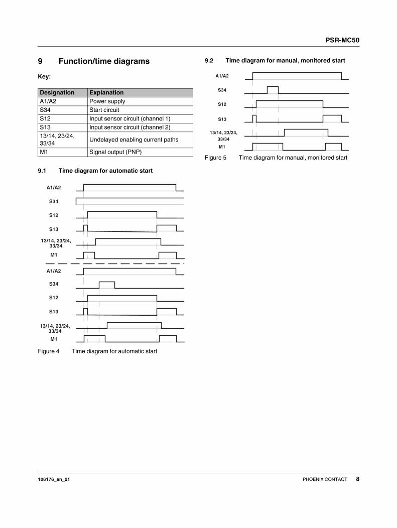
9 Function/time diagrams
Key:
9.1 Time diagram for automatic start
Figure 4 Time diagram for automatic start
9.2 Time diagram for manual, monitored start
Figure 5 Time diagram for manual, monitored start
Designation Explanation
A1/A2 Power supply
S34 Start circuit
S12 Input sensor circuit (channel 1)
S13 Input sensor circuit (channel 2)
13/14, 23/24,
33/34Undelayed enabling current paths
M1 Signal output (PNP)
A1/A2
S34
S12
S13
13/14, 23/24,33/34
M1
A1/A2
S34
S12
S13
13/14, 23/24,33/34
M1
A1/A2
S34
S12
S13
13/14, 23/24,
33/34
M1

PSR-MC50
106176_en_01 PHOENIX CONTACT 9
10 Operating and indication elements
10.1 Connection versions
Figure 6 Connection versions
1 COMBICON plug-in screw terminal block
2 COMBICON plug-in spring-cage terminal block
3 Metal lock for fixing to DIN rail
Figure 7 Year of manufacture of the device
10.2 Connection assignment
0,5-0,6 Nm5-7 lb In
PSR-...-SC
7 mm
AWG 24-12
0,2-2,5 mm2
PSR-...-SP
8 mm
AWG 24-16
0,2-1,5 mm2
PHOENIX CONTACT GmbH & CO.KG
Flachsmarktstrasse 8
32825 Blomberg, Germany
PSR-...Ord.-No.: xx xx xxx
Phoenix Safety Relays
Documentation
PS
R-.
..
PWR
PHOENIX CONTACT GmbH & CO.KG
Flachsmarktstrasse 8
32825 Blomberg, Germany
PSR-...Ord.-No.: xx xx xxx
Phoenix Safety Relays
Documentation
PS
R-.
..
PWR
21
3
The year the device was constructed can be
found underneath the CE designation on the
housing.
Documentation
PS
R-.
..
PWR
14
xxx
elays
Figure Designation Explanation
A1 +24 V power supply
A2 0 V power supply
M1 Signal output (PNP)
S34 Start circuit
S12 Input sensor circuit (channel 1)
S13 Input sensor circuit (channel 2)
PWR Power LED (green)
IN1/2 Status indicator sensor circuit; LED (green)
K1 Status indicator safety circuit; LED (green)
K2 Status indicator safety circuit; LED (green)
13/14 Undelayed enabling current paths
23/24
33/34
A1 A2
M1
S12 S13
S34
13 14
23
33 34
24
PWR
IN 1/2
K1
K2
PS
R-M
C5
0

PSR-MC50
106176_en_01 PHOENIX CONTACT 10
11 Mounting and connection
Mount the module on a 35 mm DIN rail according to
EN 60715.
Figure 8 Mounting and removing
Connect the cables to the connection terminal blocks using
a screwdriver.
Figure 9 Connecting the cables for PSR-...-SC
(screw terminal block)
Figure 10 Connecting the cables for PSR-...-SC
(spring-cage terminal block)
12 Startup
Apply the rated control supply voltage (24 V DC) at terminal
blocks A1/A2. The PWR LED lights up.
Close sensor circuit channel 1 (24 V/S12) and open chan-
nel 2 (24 V/S13). The IN1/2 LED lights up.
Automatic or manual, monitored start:
Close contacts A1/S34 as follows.
Figure 11 Connection of automatic or manual, monitored
start
1 Automatic start
2 Manual, monitored start with monitored contact exten-
sion
3 Manual, monitored start
When automatic start is selected, the enabling current paths
close.
For manual, monitored start, first press the reset button. The
release of the button causes the enabling current paths to
close.
The K1 and K2 LEDs light up.
If the supply voltage drops or the safety equipment is
opened, the enabling current paths of the output circuits (13/
14, 23/24, 33/34) open and the contacts enter the safe state.
For compliance with UL approval, use copper
wire that is approved up to 60°C/75°C.
0,5-0,6 Nm5-7 lb In
7 mm
AWG 24-14
0,2-2,5 mm2PSR-...-SC
A
B
A
A
B 8 mm
AWG 24-16
0,2-1,5 mm2PSR-...-SP
0V S34
1
0V
K3
K4
A1 S34
2
24V DC
A1 S34
3
24V DC

PSR-MC50
106176_en_01 PHOENIX CONTACT 11
13 Calculating the power dissipation
Input power dissipation
PInput = UB² / (US/IS)
Contact power dissipation
With the same load currents:
PContact = n IL² 50 mΩ
With different load currents:
PContact = (IL1² + IL2
² + ... + ILn
²) 50 mΩ
Total power dissipation
PTotal =PInput + PContact
therefore
PTotal = UB² / (US/IS) + n IL
² 50 mΩ
or
PTotal = UB² / (US/IS) + (IL1
² + IL2
² + ... + ILn
²) 50 mΩ
Key:
The total power dissipation of the safety relay
is based on the input power dissipation and
the contact power dissipation for the same
and for different load currents.
Designation Explanation
P Power dissipation in mW
UB Applied operating voltage
US Rated control supply voltage
IS Rated control supply current
n Number of enabling current paths used
IL Contact load current

PSR-MC50
106176_en_01 PHOENIX CONTACT 12
14 Diagnostics
The following section describes the LED indicators for gen-
eral states and error messages as well as possible causes
and remedies.
Function test/proof test
14.1 General states
14.2 Error Messages
Use the function test to check the safety func-
tion. To do this, request the safety function
once by pressing the emergency stop button,
for example. Check whether the safety func-
tion is running correctly by switching the de-
vice on again via the sensor circuits.
PWR
LED
IN1/2
LED
K1
LED
K2
LED
State Notes
ON OFF OFF OFF All relays are not activated. The sensor
circuit is off.
Possible error see error messages
ON ON OFF OFF The sensor circuit is active. Relays K1
and K2 are ready to start and await reset/
start command (S34).
-
ON ON ON ON The sensor circuit is active. All relays are
picked up.
-
PWR
LED
IN1/2
LED
K1
LED
K2
LED
State Possible cause Remedy
ON OFF OFF OFF The sensor circuit is ac-
tively controlled, but no
input LEDs are lit up.
Internal cross-circuit de-
tection (via non-equiva-
lence) is active: potential
cross-circuit in the sensor
circuit.
Switch off the operating volt-
age and rectify the cross-cir-
cuit. Then perform a func-
tion test.
ON ON OFF OFF The sensor circuit is ac-
tive. The reset/start circuit
(S34) is/was activated.
The safety circuit (K1 and
K2) is not picking up.
External error: the read-
back contact (external ac-
tuator) is open in the reset
circuit.
Internal error:
1. The diagnostic contact
is not working correctly.
2. An N/O contact is
welded.
External error: check the ac-
tuator.
Internal error: perform a
power down reset with sub-
sequent function test. If the
error occurs again after
the function test, replace
the device.
ON ON OFF OFF The sensor circuit is ac-
tive. The reset/start circuit
(S34) is/was activated.
The safety circuit (K1 and
K2) is not picking up.
Error during manual reset
S34 (stuck-at at the in-
put).
Remove the error in the
reset/start circuit. Then per-
form a function test.

PSR-MC50
106176_en_01 PHOENIX CONTACT 13
ON ON OFF ON The sensor circuit is ac-
tive. The reset/start circuit
(S34) is/was activated.
The safety circuit (K1) is
not picking up.
External error: sensor cir-
cuit channel 1 was
opened and reactivated.
Internal error: diagnostics
active.
External error: check the
sensor circuit.
Internal error: perform a
power down reset with sub-
sequent function test. If the
error occurs again after
the function test, replace
the device.
ON ON ON OFF The sensor circuit is ac-
tive. The reset/start circuit
(S34) is/was activated.
The safety circuit (K2) is
not picking up.
External error: sensor cir-
cuit channel 2 was closed
and reactivated.
Internal error: diagnostics
active.
External error: check the
sensor circuit.
Internal error: perform a
power down reset with sub-
sequent function test. If the
error occurs again after
the function test, replace
the device.
OFF OFF OFF OFF The sensor circuit is ac-
tive.
1. No supply voltage at
A1/A
2. Over- or undervoltage
at A1
Check the supply voltage.
PWR
LED
IN1/2
LED
K1
LED
K2
LED
State Possible cause Remedy

PSR-MC50
106176_en_01 PHOENIX CONTACT 14
15 Application examples
Key:
Applications with the PSR-MC50
15.1 Magnetic switch monitoring/automatic start
– Two-channel, non-equivalent magnetic switch monitor-
ing
– Automatic start
– Suitable up to category 4, PL e (EN ISO 13849-1),
SILCL 3 (EN 62061), if cross-circuits in the control to
the actuator can be ruled out
Figure 12 Magnetic switch monitoring/automatic start
15.2 Magnetic switch monitoring/manual, monitored
start
– Two-channel, non-equivalent magnetic switch monitor-
ing
– Manual, monitored start
– Suitable up to category 4, PL e (EN ISO 13849-1),
SILCL 3 (EN 62061), if cross-circuits in the control to
the actuator can be ruled out
Figure 13 Magnetic switch monitoring/manual, moni-
tored start
S1 = Mechanical safety door switch
S2 = Manual reset device
S3 = Solenoid switch
K1/K2 = Contactors
Cross-circuits in the cable installation can be
excluded if the safety relay and external con-
tactors K1 and K2 are located in the same
electrical installation space.
K1
K2
M
24V
K1
K2
N
L
0V
K2
K1
A1
A2
13
14
PSR-MC50
S12 S13( )
M1( )
23
24
( )
34
33
S34( )
11 12 13 14
S3
K1
K2
M
24V
K1
K2
N
L
0V
K1
K2
S2S3
11 12 13 14
A1
A2
13
14
PSR-MC50
S12S34 S13( )( )
M1( )
23
24
( )
34
33

PSR-MC50
106176_en_01 PHOENIX CONTACT 15
15.3 Safety door monitoring/automatic start
– Non-equivalent safety door monitoring
– Automatic start
– Suitable up to category 1, PL c (EN ISO 13849-1),
SILCL 1 (EN 62061)
– Suitable up to category 4, PL e (EN ISO 13849-1),
SILCL 3 (EN 62061), if cross-circuits in the control can
be excluded from the actuator and when using the two
switches in design 1
Figure 14 Safety door monitoring/automatic start
15.4 Safety door monitoring/manual, monitored
start
– Non-equivalent safety door monitoring
– Manual, monitored start
– Suitable up to category 1, PL c (EN ISO 13849-1),
SILCL 1 (EN 62061)
– Suitable up to category 4, PL e (EN ISO 13849-1),
SILCL 3 (EN 62061), if cross-circuits in the control can
be excluded from the actuator and when using the two
switches in design 1
Figure 15 Safety door monitoring/manual, monitored
start
K1
K2
M
24V
K1
K2
N
L
S1
0V
K2
K1
A1
A2
13
14
PSR-MC50
S12 S13( )
M1( )
23
24
( )
34
33
S34( )
K1
K2
M
24V
K1
K2
N
L
0V
S1K1
K2
S2
A1
A2
13
14
PSR-MC50
S12S34 S13( )( )
M1( )
23
24
( )
34
33

PSR-MC50
106176_en_01 16PHOENIX CONTACT GmbH & Co. KG • 32823 Blomberg • Germany
phoenixcontact.com
16 Revision history
Version Date Contents
00 2014-12-03 First publication
01 2015-03-05 Reverse polarity protection extended; relay type extended; dimensions updated; load
curve extended
01_c00 2015-05-19 Caption of figure 3 corrected (translation error)