david h fell part ab application sections i-x land use designation for the facility is manufacturing...
TRANSCRIPT
OPERATION PLANAUGUST 27, 2007
DAVID H. FELL AND CO., INC.EPA ID # CAL 000 110 141
TABLE OF CONTENTS PAGE #
SECTION I FACILITY IDENTIFICATION/LOCATION 3
SECTION II FACILITY OPERATION AND HAZARDOUSWASTE-MANAGEMENT PRACTICE 5
SECTION III WASTE ANALYSIS PLAN 7
SECTION IV FACILITY DESIGN (STORAGE) 13
SECTION V FACILITY DESIGN (TREATMENT) 16
SECTION VI TRAINING PLAN 28
SECTION VII INSPECTION PLAN 30
SECTION VIII CONTINGENCY PLAN 32
SECTION IX CLOSURE PLAN 36
SECTION X CERTIFICATIONS 44
1
TABLE OF ATTACHMENTS
AA-I CLOSURE COST ESTIMATE-CALIECH EMVIRONMENTAL
AA-2 REVISED CLOSURE COST ESTIMATE
AA-3 PERSONNEL TRAINING/ALTERNATIVE COORDINATOR
AA-4 SCALED FACILITY PLOT PLAN
AA-5 PROCESS FLOW DIAGRAM
AA-6 INSPECTION FORMS
AA-7 OWNERS CERTIFICATE
AA-8 I093A FORMS (baghouse # I and #2, coolant #7 A, #7B)
AA-9
AA-IO
AA 11-
AA-12
AA-13
AA-14
ENVIRONMENTAL INFORMATION FORM
P E CERTIFICATE-FOR STORAGE CONTAINMENTS, S-6, S-9,EVAPORATOR
EQUIPMENT MANUALS
WAS TE ANALYSIS PLAN
SCAQMD-PERMITS
CONTINGENCY PLAN
2
(
SECTION I FACILITY IDENTIFICATION ILOCATION
A. FACILITY NAME:EPA ID #:Address:
Telephone:Fax #:
David H. Fell & Co., Inc.CAL 000 11 0 1416009 Bandini Blvd. Bell, CA,Los Angeles County, 90040323-722-9992323-722-6567
FACILITY LAND USEThe land use designation for the facility is Manufacturing "M". The surroundingland uses are:To the north, 6001 Bandini Blvd, a trucking company,To the south, 5860 Bandini Blvd., Golden Ginger Product, company,To the east, 6015 Bandini Blvd, garment manufacturing,To the west, 6005 Bandini Blvd. a label manufacturing company.The nearest school to the facility is the Rosemead Park Elementary School,approximately one mile from the subject site. The Grace Lutheran Church islocated approximately one mile from the subject site. George James Bell, anhistorical building is located approximately five miles from the subject site.The Los Angeles Community Hospital is located approximately 2.31 miles fromthe subject site. The closest residential building to the subject site isapproximately one mile. .
ENVIRONMENTAL DATAThe subject site is located north of Bandini Blvd. between Eastern Avenue andScott Way in the City of Bell. The site lies in the Downey Plain within the CentralBasin Pressure Area, approximately one mile northeast of the Los Angeles Riverand the Long Beach (710) Freeway. The depth to groundwater is 138.5 feet anddistance to the nearest surface water (Los Angeles River) approximately one mileform the site.
This operation plan is for the renewal of the existing Standardized Permit.
B. NAME OF THE PERSON RESPONSIBLE FOR THE PREPARATION OF THEOPERATION PLAN:Max Rafii, Health, Safety & Environmental Affairs Manager, REA IIPhone: 323-722-9992Fax: 323-722-6567E-Mail: [email protected]
C: OWNER/OPERATOR AND CERTIFICATIONSee attachment (AA-7)
3

D
E
FACILITY LOCATION MAP AND SITE LAYOUT DIAGRAM
The subject site is located north ofBandini Boulevard between Eastern Avenueand Scott Way in the City of Bell, California The site is located approximatelyone mile northeast of the Long Beach Freeway (710). The Santa Ana Freeway (5)is located 0 7 miles northeast ofthe subject site The property is approximately60,750 square feet in size and is occupied by a masonry warehouse structureDavid H. Fell & Co., Inc. currently uses the structure for fabrication andprocessing of precious metals including the melting operations. The surroundingarea in the vicinity ofthe site is predominantly occupied by warehouse structuresused for commercial, warehousing and light manufacturing Bandini Boulevardborders the site to the south, parking areas boarder the site to the north and to eastA commercial structure boarders the site to the west Refer to facility plot planand the map- AT TACHMENT AA- 4
LEGAL DESCRIPTION OF PROPERTYAccording to records at the Department of Building arId Safety the site is locatedin the City of Bell, County of Los Angeles, State of Califomia and described asLots 96-105 of Rancho Laguna Tract Parcel 10, per Parcel Map 24-52 However,due to USPS route designation, the subject site is using a mailing address in theCity of Commerce and maintains a Post Office Box with an address in LosAngeles The Latitude is 34 degrees, 59', 7" and The Longitude is 118 degrees,9', 15" The Assessor's Parcel # is 6332-005-010.
{',
F CONFIDENTIALITY REQUESTS AND JUSTIFICATIONNone
4
MANAGEMENT PRACTICE:David H Fell and Company, Inc (DHF) transfers hazardous waste containing silver andother precious metals fiom known off~site generators to the facility under manifests orunder bill of lading when qualifying under small quantity exemption. The hazardouswaste is analyzed in the DHF laboratory to determine its precious metals contents Theincoming waste is processed to maximize the reclamation of precious metals in thephysical form requested by customers The DHF treatment and storage units are locatedin an enclosed building as shown in the facility plot plan.The treatment room is located on the west side of the facility divided into a melting roomon the north and powder""processing room on the south end as identified in the facilityplot plan The process flow diagram describes the treatment processes used to refine andsmelt the incoming waste in the melting room into precious metals ingots and beads andthe treatment process used to produce the precious metals powder in the powderprocessing room. The melting room, where the refining and smelting process areconducted, contains gas furnaces and induction furnaces, which are identified onattachment AA-4, the facility plot plan The furnaces produce precious metals ingots andslag. Gases and particulates fiom the furnaces and powder processing units are ducted totwo air pollution control units (baghouses), located outside in the backyard, in thenorthwest comer of the facility, as shown on the facility plot plan In the powderprocessing room, the incoming waste and slag flom the furnaces are processed throughmechanical size reduction equipment An evaporator unit located outside in the backyardofthe facility near the northeast comer evaporates hazardous waste (wash water)generated in the melting room and fabrication room, returns the solid left in theevaporator to the treatment process All storage areas are identified on the plot plan.
,I,
SECTION II FACILITY OPERATION AND HAZARDOUS WASTE
/I'"
NARRATIVE:DHF receives the hazardous waste such as (jewelry sweeps containing silver) in theshipping area via truck (south side of the building). The shipping personnel receive thematerial, examine it for the content, assign a DHF job number, establish the total weight,log it on the log book arld store it in the Hazardous Waste Storage Area (S-3), Ifit isliquid, then is stored in Storage Area S-9, located in the west side of the building. Basedon the decision of the production manager and the availability of the equipment, thematerial will go thru the required equipment and the applicable processes such as:Roaster fumace drying, thermal reductionJaw Crusher crushingBall Mill gr indingScreen screeningBlender blendingDrum thief sampling extractionMelting furnace melting
Based on the size ofthe lot, the production manager decides which of the followingfurnaces the material will be melted in:induction fumaces # 15"" # 18 A and natural gas fumaces # 19 - # 23
5
During the melting process one or more of the following chemicals is added to the meltas applicable:borax, boric acid, sodium nitrate, soda ash, copper oxide
The molten material is poured into the mold and cooled in coolants # 7A or # 7B, locatedin the melting atea It is in this stage of the process that the slag is formed on the top ofthe mold, which is removed at a later time, and stored in a drum and labeled as hazardouswaste per the requirement of California Code of Regulations, title 22 (CCR)
After the molds are cooled, the metal bars are removed and stored in metal drums and/orthe safe for shipment to an off-site facility The slag is moved to the powder processingarea and pulverized, screened, blended, and sampled
The purpose of coolant7-B is to cool down the metal bars, then the bars are stored in theproper drums and moved to the Powder Processing Area The purpose of7-A coolant isto cool down materials coming out of the Roaster Furnace
6

~
I, SECTION III WAS TE ANALYSIS PLAN
The general purpose ofDHF waste analysis plan is to characterize each waste shearn toensure that the facility is authorized to mange the waste generated or received The DHFplan is based on the requirement of applicable CCR, Title 22, and Section 66264 13regulations
A DESCRIPTION OF WASTE STREAM TYPES
TABLE I WASTE STREAMS
,(.,
Specific Vapor FlameWnstc Sh'cam Code(s) Hazard Constituents . Process Gravitv Pressurelooint ,pH Color
A Swecns D008, D011, 172, 591 toxic Silver, lead powder/melt na na na na multi color
B Wastewatcl D011,491 toxic silver evaporator/powder 1.1 na na 7 whiteC Baghouse wasle D008, D011, 172, 591 toxic silver/capoer, leadloowder na na na na dark brownD Mixed acid D011, D002, 792 corrosive Silver < 2 pH ship off site" 1.2 na na 1.0 .yellowE eupe! D008, 181 toxic lead ship off site" na n. n. n. darkF Crucible D008, 181 toxic lead shio off site" na na na na darkG Sink sludge D011,171 toxic silver Ipowder/melt na na na 7.0 whiteH Filters D011,172 toxic silver loowder/melt na na na na dark
I Slag D008 D011, 172 toxic Silver, lead powder/melt na na na na blackJ SilvCI chip D011,172 toxic silver Melt na na na na Blaxk/aravna = not apphcable*material generated in on site lab and shipped to Califomia approved off siterecycling/disposal facilities under manifest
The mixed acid waste is generated fiam the on-site lab from the fire assay to findprecious metals content Waste Stream G Sink sludge may contain residual water.
B PRE-ACCEPTANCE CRITERIA
The majority ofthe waste that DHF accepts is solid precious metal containingwaste. Occasionally, DHF will receive a drum ofliquid hazardous wastecontaining silver/gold mixed with water This is the only liquid hazardous wastethat DHF will accept The pH ofthis waste is tested to ensure that the pH isbetween 6-7. DHF does not accept alkaline or acidic waste.
TABLE II PRE- ACCEPTANCE CRITERIAFOR INCOMING HAZARDOUS WAS TE
WASTE STREAM CODE OBSERVATION RESULTScheck for color, texture, Conforms to
Jewelry Sweeps 0008, DO 11,172, 591contents, odor, generator'spackaging, label,customer profile Profile
Color, texture, packaging, Conforms toSink Sludge 0011,171 generator'sodor, label Profile
'7

C
WASTE STREAM CODE OBSERVATION RESULTScheck for color, texture, Conforms to
Filters 0011, 172contents, odor, generator'spackaging, label,customer profile Profile
check for color, texture, Conforms toSlag 0008, DO 11, 172
contents, odor,generator'spackaging, label,
customer profile Profile
color, texture, packaging, Conforms toSilver Chip 0011, .1'72 generator'slabel Profile
INSPECTION AND FINGERPRINTINGFor each incoming shipment, the DHF will track the movement of the wastes andfinger printing results Each incoming shipment is given a special number byDHF and that number is used to track that shipment as it is processed
I Inspection: DHF has procedures to inspect each shipment when wastearrives The personnel of the shipping and receiving departmcnt aretrained to inspect the incoming wastes The inspection is to determinewhether the waste matches the identity ofthe waste specified on theaccompanying manifest or shipping paper
2 Fingerprinting:The following standards will be used to judge the analyzed fingerprintsamples We will record the description if available No otherrecording are required
TABLE III. FINGER PRINTING CRITERIA FOR INCOMINGHAZARDOUS WASTE
,t,
WASTE STREAM CODE OBSERVATION RESULTScheck for color, texture, contents, Conforms to generator's
Jewelry Sweeps 0008,0011,172,591 odor, packaging, label, customer Profileprofile
Sink Sludge 0011,171Color, texture, packaging, odor, Conforms to generator'slabel Profilecheck for color, texture, contents, Conforms to generator's
Filters 0011,172 odor, packaging, label, customer Profileprofilecheck for color, texture, contents, Conforms to generator's
Slag 0008,0011,172 odor, packaging, label, customer Profileprofile
Silver Chip 0011, 172 color, texture, packaging, labelConforms to generator'sProfile
Because DHF accepts almost solely solid waste, the pre-acceptancecriteria and fingerprinting criteria are identical. The only liquidhazardous waste that DHF accepts is gold/silver mixed with water
8
The pH ofthis waste must be between 6-7 to be accepted by thefacility
If the below standards are not met, DHF will not accept the material
••
•
•
•
Ifthe material has a strong odorThe solid waste should not contain any fiee liquid unless it is ashipment of gold/silver mixed with waterIf the material is not the proper color (based on the generator'sprofile, if exist)The waste must be in Department of Transportation (DOT)approved containers, labeled and properly sealed.The material must accompany proper documentations.
(
I'.
Ifneeded and required, and if dhf recognized that there has been achange in the profile ofthe lot received from the customer, dhf will take the sample flomthe incoming lot, and have it analyzed by the on Site laboratory to determine if there arehazardous components in the lot
3 Outgoing Waste Shipment: To ensure the outgoing shipment can beaccepted by designated treatment, storage, or disposal facilities, and toensure the completion of the treatment at the facility, DHF shall testthe outgoing shipment or end-point materiaL If required andapplicable, the on Site laboratory personnel will take samples forverifications and analysis using instrumental methods of analysis (Xray, ICP). The production manager, shipping and receiving personnel,environmental manager are trained to visually inspect the outgoingshipments for compliance with CCR 22 Regulations They make surethat the Health arld Safety of the people and the Environment areprotected The metals, Au, Ag, Pt, Pd, Rh, Cu, Fe, Zn, As, Sb, Pb, Sn,Te, Br, can be identified by using X-ray and ICP techniques, however,these metals are not always present in the lots processed by dhf.
Note: The production mar1ager, shipping and receiving personnel, health, safety arldenvironmental affairs manager are trained to ensure that all material that are accepted inthe facility for processing are also visually inspected for the safety of the persormel andthe environment The Regulation and requirement of CCR 22 will be followed in thisaspect The health, safety and environmental affairs manager at the site, ensures that thegenerator's waste profile are up-dated and verified annually. If needed, the generatorsare required to submit new waste profile data, when DHF is notified or has reason tobelieve that the generator's process or operations have changed
SUMMARY OF THE PLAN: Material Generated On-Site1 Types of waste generated at the facility:
9
abc
2
ab.cd
3ab.
4abc
5a
bc.d
6abc
Precious metal bearing acidFire assay cupelsFire assay crucibleInformation that must be known to transfer, treat, and store thewaste:Solid 01 liquidphPrecious metal contentBase metal contentAnalysis performed by generatorVisual inspection to determine whether material is solid or liquidOther analysis is performed by the treatment/recycling facility asneededAnalysis performed by treatment/recycling facilitypH testPrecious metal analysisBase metal analysisParameters analyzed and rationale for this selection:Solid vs .. liquid- Determine proper storage and transportationrequirements.pH- Determine treatment methodsPrecious metal content- Determine treatment methodsBase metal content- Determine treatment methods ..Test methodsSolid Vs Liquid: visual inspectionpH paper or instrumentationPrecious metal content: ICP, AA, XRF, fire assay
(
/
("
Note: If there is a dispute over the metal content of the incoming shipment, the on sitelaboratory personnel, will send sample to be analyzed to a California accreditedlaboratory Normally, the on site laboratory, samples all materials to be processed at thefacility and analyzes them on site. This is done in order to settle the charges with ourcustomers Ifthe material/shipment fails pre-acceptance criteria, the owner ofthematerial will be immediately informed In most cases, the material will be returned tothem
DHF laboratory personnel are trained professionals, using applicable and approvedmetll0ds for sampling arld fingerprint analysis The. uses ofX··Ray Fluorescence, ICP,AA, and Fire Assay are practiced in the on site laboratory in order to determine the typesof metals in the incoming shipment
7 Sampling Methodsa Burnab1e mater ials
i Thermally reduce the material in an approved industrialroasting furnace.
11 Grind in a ball or rod mill
10
b
c
111 ScreenIV BlendV Sample using "pipe sampler" (drum thief)Glindable materials
Crush ifnecessary in jaw and disk crusher11. Grind in a ball or rod millIII ScreenIV Blendv Sample using "pipe samplel"
Meltable material1 Melt in approved industrial melting furnace11 Sample using evacuated glass tube sampler during melt OJ
drill bar aftel solidification
,\.
8 IdentityShould any material need to be analyzed fOJ purposes of furtheridentifying it, the sample taken by the methods described above will besent to an outside lab specializing in such matters
9 RecordsA record of the result of precious metal content tests described above iskept in the lab. The lecord will show:a The job numberb The pIecious metal content
MATERIAL RECEIVED FROM OFF-SITE:
1
2
4
Types of waste received at the facility:a Precious metal bearing metal dustb Plecious metal bearing metal sludge
Information that must be known to transfer, treat, and stole thewaste:
a Solid or liquidb Burnable, grindable or directly meltablec Precious metal contentAnalysis performed by generatorThe majority of the generators sending material to us do not perform aprofile analysis prior to shipment They call their material jewelrypolishing or sweeps, filters containing polishing dust or silvel flake orpowdel and rely on information generated over decades ofprocessing todefine its contentsUpon receipt of material from an off~site source we assume that theanalysis or description supplied to us fiom the generator is correct Priorto initial treatment of the material, we visually inspect the material toconfirm this 01 if needed we run an analysis at our labParameter analyzed for and rationale for this selectiona Solid Vs Liquid - We process only solid and sludge
11

5
6.
b
c
abc
burnable Vs Grindable Vs Meltable - Determine the first treatmentmethodPrecious Metal Content - Determine storage location anddestination of recyclable material generated hom the wasteI est methodsSolid Vs Liquid: visual inspectionBurn Vs Grind Vs Melt: Visual inspectionPrecious Metal content:i Fire assay as described in "A textbook of fire assaying by EdwardE Bugbee" Some material requires slight modifications, whichare proprietaryii Instrumental methods such as AA, ICP, XRF
Sampling Methods (the following will be performed ifisneeded).
a- The manifest numberb-Iot numberc-ph (if applicable), will be done by on site laboratory, and
shipping/receiving personnel
7 IdentityShould any material need to be analyzed for pUlposes offi.rrtheridentifying it, the sample will be sent to a California approved outsidelaboratory specializing in such matter s
12

SECIIONIV FACILITY DESIGN: STORAGE (attachment AA-4)
There are nine Hazardous Waste Storage Areas (HWS) in the facility, used for thestorage ofsolid and liquid wastes The following will be implemented byDHF:A On each unit, a log sheet is provided to record the activity of that unit
B All waste is stored in DOT (Department of Transportation) approved containers
C The facility will not stack containers more than two high in any ofthe HWS's
D All hazardous waste storage areas are located inside of the facility
E When necessary the liquid waste in the containment area, can be pumped out to aDOT approved drum, and disposed of by a California approved disposal facilityPlease note that DHF will not store incompatible wastes together Each wastestream is stored in separate storage area as follows:S-6, S-9 for liquid waste (Compatible Wastes)S-l, S-2, S-3, S-4, S-5, S-7 (Vault), S-8, for all other compatible wastes
F All hazardous waste shipped off~site is under a Bill of Lading, or when applicablea manifest The Health, Safety and Enviromnental Affairs Marrager and theshipping/receiving department personnel, ensure that the incompatible wastes areseparated by checking documentation and visual observation of the hazardouswaste.
(
G All dry storage areas are inspected once a week Daily inspections are made fortanks storage areas. Looking for leaking and deterioration, corrosion, DHF makessure that storage devices holding hazardous waste are always closed duringtransfer and storage, except when it is necessary to add or remove waste.
H A minimum amount of aisle space (30") between rows of storage devices must bemaintained
I Incompatible wastes, or incompatible wastes and materials, must not be placed inthe same stor age areas
J A storage area holding a hazardous waste that is incompatible with any waste orother material transferred or stored nearby in containers or tanks shall beseparated fiom the other material 01 protected fiom them by safe and appropriatemeans
Following are the locations and descriptions of the Storage Areas at DHF:
13

I ABLE IV SIORAGE AREAS FOR HAZARDOUS WAS IES
Storage i,
Area Location Use Capacity
16.0'X 100' with the capacity of21 containers of any size, totaling
solid hazardous waste, including 1159, total equivalent gallonsewehy sweeps, slag, etc Ihe waste (I.E G). Specific gravity of
is from any of the designated areas ewelry sweeps differs for each lot,powder processing Includes waste codes DOll, 172, from each customer, we cannot
S-l area, west wall D008, 171, 591 specify a value for it.solid hazardous waste, includingewelry sweeps, slag, etc Ihe waste
is fiom any ofthe designated areas 170' X 200', with the capacity ofmelt room area, Includes waste codes DOll, 172, 171, 40 containers of any size, totaling
S-2 east wall 591, D008 2200I.E.G.
in the area close to solid hazardous waste, includingthe floor scale - ewelry sweeps, slag, etc Ihe wastemetal shed, west is from any of the designated areas 170' X 35', with the capacity ofwall by the roll-up Includes waste codes DO I 1, In, 10 containers of any size, totaling
S-3 door D008,591 550 IE.G. .
,solid hazardous waste, including l
"excluded recyclable material, slag,.ewelry sweeps and powder. The
close to the east waste is fiom any ofthe designated 210' X 18 0', with the capacity ofwall in the area of areas. Includes waste codes DO I I, 80 containers of any size, totaling
5-4 the floor scale. In, In, D008, 591 4400 I.E.G.
solid hazardous waste, including slag,ewelry sweep, evaporator waste,
baghouses waste, and other solidhazardous waste, containing precious
the powder metals Ihe waste is fiom any of the 65' X 6.0', with, the capacity ofprocessmg room, designated areas Includes waste 10 containers of any size totaling
5-5 south wall. codes DOll, 171, In, 591, D008 550 I.E.G.5 0' X 50' and has secondarycontainments per CCR22Regulations This unit has the
Ihe liquid, mixed acid waste capacity of 133 gallons of any size(hydrochloric and nitric), containing containers The containment ofthesilver, generated fiom the activities ofArea, is made of plastic and canthe site laboratory and virgin acids holds 11 0 % of the largest
Fabrication Room are stored in this area Includes waste container stored, per requirement5-6 # 2, west wall. code DOll, D002, 172, 792 ofthe CCR I itle 22. (
14

solid hazardous waste including,ewelry sweeps, excluded recyclable
opposite material, slag, laboratory samplesFabrication Room Ihis waste is flom any other
.
#2, center of the desi gnated areas Includes waste 16 .. 0' X 12.0', with the capacity ofS-7 building. codes DOll, 172, 171, D008, 591 1100 I E.G. of any size containers,
solid hazardous waste - cupel,crucible containing lead that isgenerated fiom the laboratory
Fabrication Room activities, Includes waste codes 12 0' X 7,0', with the capacity ofS-8 # 2, west wall D008,181 330 1. E G. of any size containers.
50' X 5 0' and has secondarycontainments per CCRnRegulations, This unit has the
Powder capacity of 115 gallons of any sizeProcessing Area, containers, The containment iswest wall), close liquid hazardous waste containing made of plastic and can hold 110to the exit to the precious metals.. Includes waste % ofthe largest container stored,
S-9 back parking lot. codes DOll, 172, 171. per requirement of CCR, Title 22,
Please note that, the vapor pressure, flame point/auto ignition temperature is notapplicable in the waste streams mentioned above Ihe specific gravity for jewelry sweepsis different for each customer, depending the components included in the lot, the pH ofthe mixed acid waste is less than 2,0, Ihe color of the jewelry sweeps is normally gray,the color of mixed acid is yellowish, the color of slag is black, and the color of the cupelsand crucibles are light to black.
Coolant 7A is located in the melt room and 7B is located in the powder processing room,are used for cooling of bars and other materials, containing precions metals Coolants 7Aarld 7B take sweeps, sink sludge, baghouse dust, sludge, filters with waste codes D008,DOll, 171, 172 and 591 Coolant 7A additionally takes slag These metal bars are storedin the S-7 vault or other designated Storage Areas (S-2, S-4), and/or are stored in thefacility as needed
Ihe total capacity of Coolant 7-A and 7-B is 550 IE G each
15

SECTION V FACILITY DESIGN: TREATMENT (attachment AA-5)And (attachment AA-4)
TABLE V PROCESS EQUIPMENT-WASTE STREAM
Unit# Description Waste Stream Pr ocessed
1 ball mill sweep, baqhouse dust, sludqe, filters, slaq, (D008, DO 11, 171, 172, 591)
sweep, baghouse dust, wastewater, sludge, filters, slag, (D011, 171,2 screen 172, 591, D008)
sweep, baghouse dust, wastewater, sink sludge, filters, slag, (D011, 171,3 screen 172, 591, D008)
sweep, baghouse dust, sink slUdge, filters, slag, (D011, 171, 172, 591,4 ball mill D008) .
sweep, baghouse dust, wastewater, sink sludge, filters, slag, (D011, 171,5 screen 172, 591, D008)
sweep, wastewater, baghouse dust, sink sludge, filters, slag, (D011, 171,6 v blender 172, 591, D008)
sweep, wastewater, baghouse dust, sink sludge, filters, slag, (D008,7 blender D011, 171, 172, 591) .
sweep, baghouse dust, sink slUdge, filters, slag, (D011, 171, 172, 591,8 rod mill D008)
sweep, baghouse dust, sink slUdge, filters, slag, (D011, 171, 172, 591,9 rod mill D008)
10 pulverizer Not operational
11 Jaw crusher Not operationalsweep, baghouse dust, sink slUdge, filters, slag, (D011, 171, 172, 591,
12 ball mill D008)·
13 iaw crusher sweeps, slaq 10011, 172, 591, D008)
sweep, sink sludge, baghouse dust, sludge, filters, (D011, 171, 172, 591,14 roaster furnace D008)
15 induction furnace sweep, sink sludqe, filters, slaq, silver chip (D011, 171, 172, 591, D008)
16 induction furnace sweep, sink sludge, fillers, slag, silver chip (D011, 171, 172, 591, D008)
17 induction furnace sweep, sink Sludqe, filters, slaq, silver chip (D011, 171, 172, 591, D008)
18 induction furnace sweep, sink sludqe, filters, slaq, silver chip (D011, 171, 172, 591, D008)
18A induction furnace sweep, sink sludge, filters, slag, silver chip ID011, 171, 172,591, D008)
19 gas furnace sweep, sink sludqe, filters, slaq, silver chip (D011, 171, 172, 591, D008)
20 gas furnace sweep, sink sludqe, filters, slaq, silver chip (D011, 171,172,591, D008)
21 gas furnace sweim, sink sludqe, filters, slaq, silver chip (D011, 171, 172, 591, D008)
22 gas furnace sweep, sink sludge, filters, slaq, silver chip (0011, 171, 172, 591, D008)
23 gas furnace sweep, sink sludqe, filters, slaq, silver chip (D011, 171, 172, 591, D008)
16
,/
I,
(
("

/"I
/
I'.
Unit # Description Waste Stream Processed
Emissions from ali powder and Melt room equipment goes to the units,BH1 baghouse via ducting (0011, 172, 591, 0008)
Emissions from ali powder and Melt room eqUipment goes to the units,BH2 baghouse via ductina 10011,172,591,0008,591)
COOling water and wash water from meit Room and fabrication Roomevaporator evaporator Igoes to the unit (0011, 171, 491, 0008)
Unit #1 BALLMILL (D008,DOll,171,172,591)This unit is located in the powder processing area. Hazardous waste from any of thedesignated streanlS either as received, following the roaster furnace, or the jaw crusher isplaced in the ball mill by hand scooping/shoveling and sealed. The mill vibrates causingsteel balls to grind the material to a fine powder The mill empties into the screen. Thescreen separates the + and -60 mesh material The fines fall into a sealed drum Theoversize is swept out
PROCESS CAPACITY:170 pounds/batch3 hrs/d, 5d/wk, 52 wk/yr (average)10hrs/d, 5d/wk, 52 wk, yr (maximum)1-2 hourslbatchLoading 10 minuteUnloading 10 minutesMaximum capacity per month, approximately 18700 Pounds
Unit #2 SCREEN (DOll, 171, 172, 591, D008)This unit is located in the powder processing area.. Hazardous waste from any of thedesignated streams either as received, following the roaster furnace, jaw crusher, ball millor Rod mill is placed in the screen by hand scooping/shoveling or is directly input fiomball mill Material greater and smaller than 60 mesh are separated by vibrating the screenThe fines fall directly into a sealed drum The oversize is swept out
PROCESS CAPACITY:100 pounds/batch30-60 minutes3 hrs d, 5d/wk, 52 wks/Yl (average)10 hrs/d, 5d/wk, 52 wks/yr (maximum)Loading - 10 minutesUnloading - 10 minutesMaximum capacity per month, approximately 10500 00 pounds
Unit #3 SCREEN (DOll, 171, 172, 591, D008)This unit is located in the powder pIOcessing room Hazardous waste from any of thedesignated streams either as received following the lOaster furnace, jaw cIUsher, ball millor rod mill is placed in the screen hand scooping/shoveling or is directly input from ball
17

mill Material greater and smaller than 60 mesh are separated by vibrating the screenThe fines fall directly into a sealed drum. The oversize is swept out
PROCESS DESIGN CAPACITY:100 pounds/batch30 - 60 minute/batch3 hrs/d, 5 d/wk, 52 wks/yr (average)10 hrs/d, 5d/wk, 52 wks/yr (maximum)Loading - 10 minutesUnloading 10 minutesMaximum capacity per month approximately, 21000 00 pounds
Unit #4 BALLMILL (DOll, 171, 172, 591, D008)This unit is located in the powder processing area.. Hazardous waste from any of thedesignated streams either as received, following the roaster furnace or jaw crusher isplaced in the ball mill by hand scooping/shoveling and sealed. The mill vibrates causingsteel balls to grind the material to a fine powder. The mill empties into the screen. Thescreen separates the + and -60 mesh material The fines fall into a sealed drum. Theoversize is swept out.
PROCESS CAPACITY:170 pounds/batch30 - 60 minutes/batch3 hrs/d, 5 d/wk, 52 wks/yr (average)10 hrs/d, 5d/wk, 52 wks/yr (maximum)Loading - 10 minutesUnloading 10 minutesMaximum capacity per month, approximately 10500.00 pounds
Unit #5 SCREEN (DOll, In, 172, 591, D008)This unit is located in the powder processing area Hazardous waste from any of the.designated streams either as received, following the roaster furnace, jaw crusher, ball millor rod mill is placed on the screen by hand scooping/shoveling The screen vibratesseparating + and -60 mesh powder. Powder passing through the screen goes directly intoa sealed drum The oversize is swept out
PROCESS CAPACITY:120 pounds/batch30 - 60 minutes per batch:3 hrs/d, 5d/wk, 52 wks/yr (average)10 hls/d, 5 d/wk, 52 wks/yrLoading - 10 minutesUnloading -10 minutesMaximum capacity per month, approximatelyl0500..00 ponnds
18
(
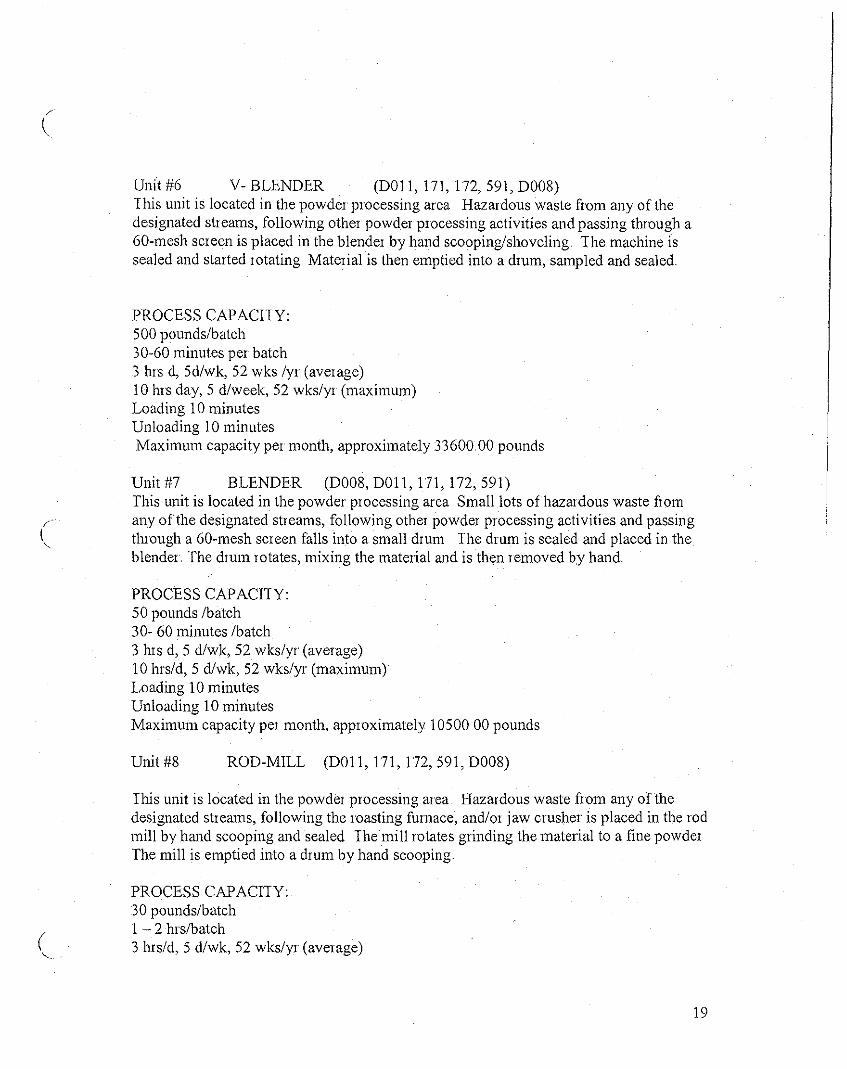
Unit #6 V- BLENDER (DOlI, 171, 172, 591, D008)This unit is located in the powder processing area Hazardous waste from any of thedesignated streams, following other powder processing activities and passing through a60-mesh screen is placed in the blender by hand scooping/shoveling.. The machine issealed and started rotating. Material is then emptied into a drum, sampled and sealed.
PROCESS CAPACITY:500 pounds/batch30-60 minutes per batch3 hrs d, 5d/wk, 52 wks /yr (average)10 hrs day, 5 d/week, 52 wks/yr (maximum)Loading 10 minutesUnloading 10 minutesMaximum capacity per month, approximately 33600 00 pounds
Unit #7 BLENDER (D008, DOll, 171, 172, 591)This unit is located in the powder processing area Small lots of hazardous waste fromany ofthe designated streams, following other powder processing activities and passingthrough a 60-mesh screen falls into a small drum The drum is sealed and placed in theblender. The drum rotates, mixing the material and is then removed by hand
PROCESS CAPACITY:50 pounds /batch30- 60 minutes /batch3 hrs d, 5 d/wk, 52 wks/yr (average)10 hrs/d, 5 d/wk, 52 wks/yr (maximum)Loading 10 minutesUnloading 10 minutesMaximum capacity per month, approximately 10500 00 pounds
Unit #8 ROD-MILL (DOll, 171, 172,591, D008)
('-.
This unit is located in the powder processing area. Hazardous waste fiom any ofthedesignated streams, following the roasting furnace, and/or jaw crusher is placed in the rodmill by hand scooping and sealed The mill rotates grinding the material to a fine powderThe mill is emptied into a drum by hand scooping
PROCESS CAPACITY:30 pounds/batch1 - 2 hrslbatch3 hrs/d, 5 d/wk, 52 wks/yr (average)
19

10 lm/d, 5d/wk, 52 wks/yr (maximum)Loading 10 minutesUnloading 10 minutesMaximum capacity per month, approximately, 7000 pounds
Unit #9 ROD-MILL (DOlI, 171, 172, 591, D008)This unit is located in the powder processing area. Hazardous waste flom any ofthedesignated streams, following the roasting furnace, and/orjaw crusher is placed in the rodmill by hand scooping and sealed The mill rotates grinding the material to a fine powderThe mill is emptied into a drum by hand scooping
PROCESS CAPACITY:30 pound/batchI - 2 hrs/batch3 hrs/d, 5 d, wk, 52 wks/yr (average)10 hrs/d, 5 d/wk, 52 wks/yr (maximum)Loading - 10 minutesUnloading 10-minutesMaximum capacity per month, approximately, 7000 pounds
Unit #12 BALL MILL (DOll, 171, 172,591, D008)This unit is located in the powder processing area. Hazardous waste flom any of thedesignated streams either as received, following the roaster furnace orjaw crusher isplaced in the ball mill by shoveling and sealed. The mill rotates causing steel balls togrind the material to a fine powder The mill is emptied to a tray by handscooping/shoveling
PROCESS CAPACITY:400 pounds/batch3 - 6 hrs/batch3 hrs/d, 5 d, wk, 52 wks/yr (average)10 hrs d, 5 d/wk, 52 wks/yr (maximum)Loading 10 minutesUnloading 10 minutesMaximum capacity per month, approximately 124500 00 pounds
Unit #13 JAW CRUSHER (DOll, 172, D008, 591)This unit is located in the powder processing area Hazardous waste fiom any of thedesignated streams, following the roaster finnace or as received is pOllled down the throatofthe jaw crusher by hand scooping/shoveling The crushed particles fall into a sealedtray
PROCESS CAPACITY:
20
(
('-

(
500 pound/batch3- 6 hrs/batchohrs/d, 0 d/wk, 5 wks /yr (aver age)10 hrs/d, 4 d/wk, 50 wks/yr (maximum)Loading - 10 minutesUnloading 10 minutesMaximum capacity per month, approximately 18000 pounds.
Unit #14 ROASTER FURNACE (DOll, 172, 171, 591,D008)This unit is located in the melt room Hazardous waste from any of the designatedstreams is placed into trays by hand scooping/shoveling The trays are placed into theroaster fllJnace ahd burned at approximately 900 - 1100 F The tr ays then are placed inthe cooling box and cooled, and then the material is either processed in the powderprocessing section (grinding or screening) or is stored in a dlUm
OPERAIING CAPACITY;200 pounds/batch2 hrs/batch3 hIs /d, 4 d/wk, 50 wks/yr (average)10 hrs/d, 4 d/wk, 50 wks/yr (maximum)Loading - 15 minutesUnloading ~ 15 minutesMaximum capacity per month, approximately 18000 pounds.
Unit # 15 INDUCTION FURNACE (DOll, 171,172, D008, 591 )Ihis unit is located in the melt room Hazardous waste [10m any of the designated wastestreams is placed in a crucible in the furnace The material is brought up to between 1900degree F and 2300 degree F. All of the material is poured out ofthe crucible into moldsOne or more chemical (boric acid, soda ash, sodium nitrate) are added based on the typeand quantity of the material charged to the furnace. Ihe slag generated from thisoperation, is put into a 0..0 I approved 55-gallon metal drum for storage and additionalprocessing at a later date After the mold cools, the bars are removed flom the molds byhand
PROCESS CAPACITY:200 TO /batch6 ills /d, 4d/wk, 50 wks/yr (average)10 hIs/d, 4 d/wk, 50 wks/yr (maximum)15 minutes/batchLoading - 10 minutesUnloading - 10 minutesMaximum capacity per month, approximately 18000 I lOy Ounces
Unit # 16 INDUCTION FURNACE (DOll, 171, 172, 591, D008)
21
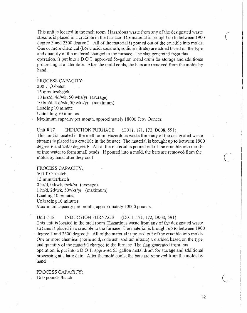
This unit is located in the melt room Hazardous waste fjom any ofthe designated waste ,"streams is placed in a crucible in the flllnace The material is brought up to between 1900 I,degree F and 2300 degree F All of the material is poured out of the crucible into moldsOne or more chemical (boric acid, soda ash, sodium nitrate) are added based on the typeand quantity of the material charged to the flllnace. The slag generated fjom thisoperation, is put into a DO I. approved 55-gallon metal drum for storage and additionalprocessing at a later date. After the mold cools, the bars are removed from the molds byhand
PROCESS CAPAClIY:200 I O/batch15 minutes/batch10 hrs/d, 4d/wk, 50 wks/yr (average)10 hrs/d, 4 d/wk, 50 wks/yr (maximum)Loading 10 minuteUnloading 10 minutesMaximum capacity per month, approximately 18000 I roy Ounces
Unit # 17 INDUCTION FURNACE (DOll, 171, 172, D008, 591)Ihis unit is located in the melt room Hazardous waste from any ofthe designated wastestreams is placed in a crucible in the fumace The material is brought up to between 1900degree F and 2300 degree F All ofthe material is poured out ofthe crucible into moldsor into water to form small beads If poured into a mold, the bars are removed fjom the
(molds by hand after they cool "
PROCESS CAPAClIY:500 TO/batch15 minutes/batchohI/d, Od/wk, Owk/yr (average)1 lu/d, 2d/wk, 50wks/yr (maximum)Loading 10 minutesUnloading 10 minutesMaximum capacity per month, approximately 10000 pounds.
Unit # 18 INDUCTION FURNACE (DOll, 171, 172, D008, 591)Ihis unit is located in the melt room Hazardous waste fjom any ofthe designated wastestreams is placed in a crucible in the fumace The material is brought up to between 1900degree F and 2300 degree F All ofthe material is poured out ofthe crucible into moldsOne or more chemical (boric acid, soda ash, sodium nitrate) ale added based on the typeand quantity ofthe material charged to the fumace Ihe slag generated fjom thisoperation, is put into aDO I approved 55··gallon metal drum for storage and additionalprocessing at a later date After the mold cools, the bars are removed fjom the molds byhand
PROCESS CAPAClIY:16 0 pounds /batch
22

(
,I,
30 minutes /batch4 hrs/d, 4-d/ wk, 50 wk/yr (average)10 hrs/d, 4d/wk, 50 wks/yr (maximum)Loading 10-minutesUnloading 10-minutesMaximum capacity per month, approximately 30000 pounds
Unit # 18A INDUCTION FURNACE (DOlI, 171, 172, D008, 591)Ihis unit is located in the melt room Hazardous waste flom any of the designated wastestreams is placed in a crucible in the furnace The material is brought up to between 1900degree F and 2.300 degree F All of the material is poured out of the crucible into moldsOne or more chemical (boric acid, soda ash, sodium nitrate) are added based on the typeand quantity ofthe material charged to the fumace Ihe slag generated from thisoperation, is put into a DO. I approved 55-gallon metal drum for storage and additionalprocessing at a later date After the mold cools, the bars are removed flam the molds byhand
PROCESS CAPACITY:450 pounds /batch.30 minutes/batch4 hrs/d, 4d/wk, 50 wks/yr (average)10 hrs/d, 4d/wk, 50 wks/yr (maximum)Loading 10 -minutesUnloading- 10 minutesMaximum capacity per month, approximately 30000 pounds
Unit # 19 NATURAL GAS FURNACE (DOll, 171, 172, D008, 591)Ihis unit is located in the melt room Hazardous waste from any of the designated wastestreams is placed in a crucible in the flrmace Ihe material is brought up to between 1900degree F and 2300 degree F All of the material is poured out of the crucible into moldsOne or more chemical (boric acid, soda ash, borax, sodium nitrate) are added based onthe type and quantity ofthe material charged to the fumace Ihe slag generated from thisoperation, is put into a DO I approved 55-gallon metal drum for storage and additionalprocessing at a later date. After the mold cools, the bars are removed from the molds byhand
PROCESS CAPACITY:300 I 0 /batch1 0 Hr/batchohr/d, 0 d/wk, 0 wk/yr (average)10 hrs/d, 2d/wk, 50 wkiyr (maximum)Loading 10 minutesUnloading 10 minutesMaximum capacity per month, approximately 14000 pounds
23
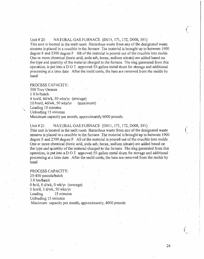
Unit # 20 NATURAL GAS FURNACE (DOll, 171, 172, D008, 591)This unit is located in the melt room Hazardous waste from any of the designated wastestreams is placed in a crucible in the furnace The material is brought up to between 1900degree F and 2300 degree F All ofthe material is poured out of the crucible into moldsOne or more chemical (boric acid, soda ash, borax, sodium nitrate) are added based onthe type and quantity of the material charged to the furnace. The slag generated flom thisoperation, is put into aDO. T. approved 55-gallon metal drum for storage and additionalprocessing at a later date After the mold cools, the bars are removed from the molds byhand
PROCESS CAPACITY:300 Troy Ounces1 0 hr/batch4 hrs/d, 4d/wk, 50 wks/yr (average)10 hrs/d, 4d/wk, 50 wks/yr (maximum)Loading 15 minutesUnloading 15 minutesMaximum capacity per month, approximately 6000 pounds
Unit # 21 NATURAL GAS FURNACE (DOll, 171, 172, D008, 591)This unit is located in the melt room Hazardous waste from any of the designated wastestreams is placed in a crucible in the furnace The material is brought up to between 1900degree F and 2300 degree F All of the material is poured out ofthe crucible into moldsOne or more chemical (boric acid, soda ash, borax, sodium nitrate) are added based onthe type and quantity ofthe material charged to the furnace The slag generated from thisoperation, is put into a DOT approved 55-gallon metal drum for storage and additionalprocessing at a later date. After the mold cools, the bars are removed flom the molds byhand
PROCESS CAPACITY:25-450 poundslbatch3 0 hrs/batchohr/d, 0 d/wk, 0 wk/yr (average)5 hrs/d, 3 d/wk, 50 wks/yrLoading 15 minutesUnloading 15 minutesMaximum capacity per month, approximately, 4000 pounds
24
/
(

(,
Unit # 22 NATURAL GAS FURNACE (DOll, 171, l72,DOOS, 591)This unit is located in the melt room Hazardous waste flom any ofthe designated wastestreams is placed in a crucible in the £tanace.. The material is brought up to between 1900degree F and 2300 degree F All of the material is poured out of the crucible into moldsOne or more chemical (boric acid, soda ash, borax, sodium nitrate) are added based onthe type and quantity of the material charged to the furnace The slag generated from thisoperation, is put into aDO T approved 55-gallon metal drum for storage and additionalpIOcessing at a later date Afler the mold cools, the bars are removed flom the molds byhand
PROCESS CAPACITY;250 - 1500 pound/batch3 0 ills/batchohr/d, 0 d/wk, 0 wk/yr (average)10 hrs/d, 3 d/wk, 50 wk/yr (maximum)Loading 30 minutesUnloading 30 minutesMaximum capacity per month, approximately 100000 pounds
Unit # 23 NATURAL GAS FURNACE (DOll, 171, 172, DOOS, 591)This unit is located in the melt room Hazardous waste flom any ofthe designated wastestreams is placed in a crucible in the furnace. The material is brought up to between 1900degree F and 2300 degree F All ofthe material is poured out of the crucible into moldsOne or mOle chemical (boric acid, soda ash, borax, sodium nitrate) are added based onthe type and quantity ofthe material charged to the furnace The slag generated from thisoperation, is put into a DO T approved 55-gallon metaldrUl11 for storage and additionalpIOcessing at a later date After the mold cools, the bars are removed from the molds byhand
PROCESS CAPACITY:250-1500 pounds/batch3 0 ills/batchohr/d, 0 d/wk, 0 wk/yr (average)10 hrs/d, 3 d/wk, 50 wk/yr (maximum)Loading 30 minutesUnloading 30 minutesMaximum capacity per month, approximately 100000 pounds
TWO IDENTICAL BAGHOUSES FOR EMISSION CONTROL - (#1 and #2),These units, located in the backyard of the facility (north side), capture all the emissions(metal dust, particulates) generated, due to the activities of the melting and powderprocessing operations (waste code DOOS, DOll, 172,591) Each unit contains 210 bags to
25

capture the emissions from the processes When the bags are saturated with contaminants,they are removed by hand and burned at the Roaster Furnace # 14, to recover any existingprecious metals, including silver Both units are under permit from South Coast AirQuality Management District (SCAQMD) The bags will prevent any contaminantsfrom being emitted to the environment. (D008, DOll, 172,591)
EVAPORATOR: (waste code D008, DOll, 171,491).The evaporator, located in the backyard ofthe facility (north side), evaporates coolingwater, and wash water generated in the facility due to washing metal parts This unit hasthe capacity of250 gallons. To prevent foaming in this unit, chemical anti-foam is usedwhen needed The sludge accumulated in this unit is transfened to the roaster furnace,dried, bumed to recover any precious metals, including silver. This evaporator has asecondary containment (tank) to prevent release of liquid hazardous waste to theenvironment
PROCESS CAPACITY:250 gallons capacitycontinuous operation10 In/d,S d/wk, 50 wk/yr (average)24 hrs/d, 3 d/wk, 50 wk/yr (maximum)Maximum capacity per month, approximately 10000 pounds
There is no piping connecting the hazardous waste management units at the facility,however, these units are connected to the baghouses with ducting system.
PROCESS DESCRIPTION OF EACH WASTE STREAM:
WASTE STREAM A, SWEEPS: First get stored in storage area S-3 and then isroasted in roaster furnace # 14.. From there, the Sweeps are seutto the powderprocessing, (ball mill, Unit # 4) as needed and then Screen, Unit # 2. After that thematerial is processed in V-blender # 6, (mixed), and sampled. Ihe sample will beanalyzed by site laboratory for precious metals. (172, DOll, D008, 591).
WASTE STREAM B, WASTE WATER: All cooling /washing water hom thefacility is processed in the evaporator, the remaining sludge is removed and storedin a appropriate container, labeled and sent to the Roaster furnace # 14 as neededfor drying, burning. After that the recovered precious metals in the form of powder,is sent to, powder processing section (grind, screen, blend, sample), (DOll, 491) ..
WASTE STREAM C, BAGHOUSES WASTE: The baghouse waste is stored in 55gallon metal drum.. It is then sent to the powder processing Area of the facility asneeded and mixed with other precious metals bearing metal dust and processed slag,as needed and exported. (DOll, 591, D008, 172). (ducts hom gas furnaces # 14, #15,#16, #17, #18, #18A, # 19, # 20, # 21, # 22, # 23)..
26
(
,('-. .

WASTE STREAM D, SPENT ACID (Mixed): This waste which is generated as aresult oflaboratory activities at the site is disposed by an California approveddisposal company under a Manifest. (DOll, D002, 792), as needed"
WASTE STREAM E, CUPELS: This waste which is generated as a result ofactivities at the site laboratory is disposed by an California approved disposalcompany under a Manifest" (D008, 181), as needed,
WASTE STREAM F, CRUCIBLE: This waste which is generated as a result ofactivities at the site laboratory is disposed by an California approved disposalcompany under a Manifest. (D008, 181), as needed.
WASTE STREAM G, SINK SLUDGE: This waste is dried in the Roaster furnace# 14, as needed, and sent to the powder processing Area (grind, screen, blend,sample), (DOll, 171)
WASTE STREAM H, Filters: This waste is dried in the Roaster furnace #14 asneeded and sent to the powder processing area (grind, screen, blend, sample),(DOll,l72)
WASTE STREAM I, Slag: This waste is generated as a result of melting activitiesin the melting area of the facility. The slag is stored in the 55-gallon metal drnms asneeded and sent to the powder processing (grind, screen, blend, sample)" (DOll, 172,D008)
WASTE STREAM J, SILVER CHIP: This waste is melted in anyone of thefurnaces # 15 thrn #23, depending on the size of the lot. The material is converted toa metal bar due to the melting, as needed, and stored in a 55-gallon metal drum,(DOll, 172) for storage.
27
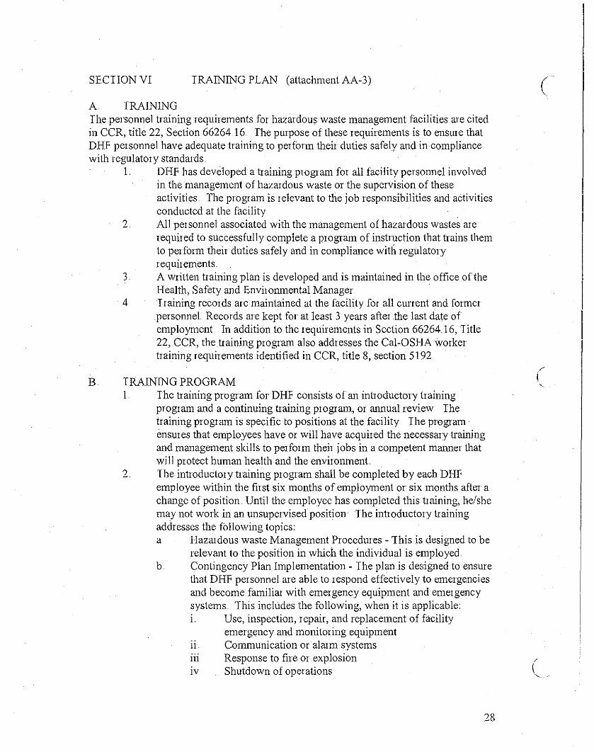
SECTION VI TRAINING PLAN (attachment AA-3) cA TRAININGThe personnel training requirements for hazardous waste management facilities are citedin CCR, title 22, Section 66264.16 The purpose ofthese requirements is to ensure thatDHF personnel have adequate training to perform their duties safely and in compliancewith regulatory standards
1. DHF has developed a training program for all facility personnel involvedin the management of hazardous waste or the supervision of theseactivities The program is relevant to the job responsibilities and activitiesconducted at the facility
2 All personnel associated with the management of hazardous wastes arerequired to successfully complete a program of instruction that trains themto perform their duties safely and in compliance with regulatoryrequirements
3 A written training plan is developed and is maintained in the office oftheHealth, Safety and Environmental Manager
4 Training records are maintained at the facility for all current and formerpersonneL Records are kept for at least 3 years after the last date ofemployment In addition to the requirements in Section 66264.16, Title22, CCR, the training program also addresses the Cal-OSHA workertraining requirements identified in CCR, title 8, section 5192
B TRAINING PROGRAM1 The training program for DHF consists ofan introductory training
program and a continuing training program, or annual review Thetraining program is specific to positions at the facility The programensures that employees have or will have acquired the necessary trainingand management skills to perform their jobs in a competent manner thatwill protect human health and the environment
2.. The introductory training program shall be completed by each DHFemployee within the first six months of employment or six months after achange ofposition Until the employee has completed this training, he/shemay not work in an unsupervised position The introductory trainingaddresses the following topics:a Hazardous waste Management Procedures - This is designed to be
relevant to the position in which the individual is employed.b. Contingency Plan Implementation - The plan is designed to ensure
that DHF personnel are able to respond effectively to emergenciesand become familiar with emergency equipment and emergencysystems.. This includes the following, when it is applicable:i. Use, inspection, repair, and replacement of facility
emergency and monitoring equipment11 Communication oralarm systems111 Response to fire or explosionIV Shutdown of operations
28
( 3 Each employee must patticipate annually in an update, or reflesher, of theinitial training.. The refiesher should keep personnel of DHF up to datewith changes at the facility, such as the chatacteristics of new wastesmanaged at the facility or the contingency plan, as well as changes in therapidly evolving field of hazardous waste management.a The training progratn will consist of classroom or on-the~job
trainingb A person trained in hazardous waste management procedures must
direct the training programc Cal-OSHA also requires that all employees of hazardous waste
facilities regulated under Chapter 6 5, Health and Safety Code obtainan initial health and safety training of 24 hours and refiesher trainingfor (8) hOUlS annually
C TRAINING RECORDSPersonnel training records ate kept at DHF facility for examination by a DISC inspectorupon request The training records for CUllent personnel are kept on file at the facilityuntil DHF closes. The training records of former employees will be available for at least3 years flom their last date of employment at the facility. If an employee is transfelledwithin DHF, their training records remain the sameTraining records must include: a job title for each position at the facility that is related tohazardous waste management, ajob description for each of those positions, and thenatnes of the employee filling those positions.. The job description, for each position,must include the skill, education, or other qualifications needed by employees to fill eachposition, and the duties of employees assigned to each position The DHF records mustdemonstrate that personnel have completed the proper training.. DHF must retain a recordof the dates on which employees received their training and annual reviews .. (attachmentAA-3) DHFCO keeps an on-site record ofjob titles and the training necessary for thatjob title It is located in the Office of Health, Safety atld Environmental Manager
29

SECTION VII INSPECTION PLAN (attachment AA-6)DHF will inspect the facility for malfunction and deteriorations, operator errors, andrelease to secondary contairllilent or the environment which may cause or may lead to therelease of hazardous waste constituents to the environment or thleaten human healthDHF will record all findings in an inspection log. This log is kept in the Office of theHealth, Safety and Environmental Affairs Manager If a problem is detected, DHF willtake necessary steps immediately to COllect the situation DHF shall inspect allmonitoring equipment, safety and emergency equipment, security devices, and operatingand structural equipment. Any time any defective item is found, DHF removes that itemfrom the operations, and it will be repaired as is applicable (attachment AA-6)
FREQUENCY OF INSPECTION BY DHF PERSONNEL:
A DAILY INSPECTIONS: (all emergency equipment)Maximum of drums together in storage area30-Inches space in the aisle between the rows of drumsWaming signsDoorwaysForkliftLoading/unloading zoneProcessing equipmentBaghouses_all equipmentEye washes/showersFire extinguishers
B. WEEKLY INSPECTION:FurnacesSecondary containmentAisle spaceAccumulation datesDrum tops fiee of spills/leakageDrum labelsIncompatible wastes not togetherRespirators, cartridges, protective clothing, fOlklifts and warning signs.Fumaces, powder processing units
C MONTHLY INSPECTIONS:Emergency Showers/EyewashFace shieldProtective glassesDisposable respirator (dust mask)First aid/equipment suppliesProtective clothing5-minute air packDecontamination equipment
30
('-...>
c
/"...
Warning signsFire detection systemLoading areasUnloading areasStOJage areasMain roadwaysGate areaPeripheryErner gency lights
31

SECTION VIII CONTINGENY PLAN ,r
I'.
A CONTINGENCY PLAN/EMERGENCY PREPAREDNESSI EMERGENCY PREPAREDNESS AND PREVENTION
David H Fell &Co Inc, has prepared the Contingency Plan in an attemptto minimize hazards to human Health or the environment from emergencysituations The provisions ofthis plan will be carried out immediatelywhenever there is an emergency that could threaten human health or theenvironment The requirements of Article 3 of Chapter 14, Title 22, CFR(Sections 6626430 et esq ) are used to produce this plan. This planidentifies facility requirements that are intended to minimize thepossibility of a fire, explosion, or any release ofhazardous waste to theenvironmentThe following equipment is present in the DHF facility in order toadequately respond to an emergency situation
2 REQUIRED EQUIPMENT
a Internal communication (PA system), which is immediatelyaccessible, to all personnel involved in the handling of hazardouswaste
b Telephone system capable of summoning emergency assistanceflom local police, Los Angeles Fire Department, or any other
Cemergency response team is also available to any employee alonewhile the facility is in operation (DHF also can use CHEMTRECEMERGENCY RESPONSE TEAM at 800-424-9300)
c Several Portable Fire extinguishers and other fire controlequipment are available on site
d. Spill control- several containers of sawdust and drychemicals/sand are stOled at the different parts of the facility foremergency uses
e Decontamination equipment- protective apron, protective gloves,safety eye glasses, boots, boots cover, soda ash, other chemicalsincluding soap, various commercial cleaning agents are availablefor decontamination purposes
f Water supply systems, including automatic sprinkler and hoses areavailable at the site Personnel at the site, fiequently inspect thesesystems to assure proper operation in the event of an emergency
3 ARRANGEMENT WITH LOCAL SERVICES AND AUTHORITIESDHF has a contract with CHEMTREC to respond in case of hazardouswaste spills at the facility 01 any other locations (800-424-9300)
4 WHAT IS A CONTIGENCY PLAN AND WHY IT IS NEEDEDDavid H Fell & Co, Inc, has prepared the Contingency Plan, to minimize ,hazards to human health or the environment from emergency situations (
'-...
32
rI\.'.
5
The provisions of this plan will be canied out immediately whenever thereis an emergency that could threaten human health or the environmentThis plan provides a structural list ofprocedures that allow DHF torespond immediately and appropriately to incidents such as fires,explosions and unplanned release, or spills of hazardous wastes orhazardous waste constituents to the air, soil or surface water. This processminimizes the hazards to human health and the environment that mayoccur as a result of emer gencies involving hazardous wastes The DHFContingency Plan is based on the requirements of the regulations thatspecify in the California Code of Regulations (CCR), Title 22, Chapter 14,Article 4, and beginning with 66264.50 DHF provides one copy of theplan, and any revisions to each of the agencies that may provideemergency response, including local police departments, fire departments,hospitals, and local and State emergency response teams The plan isrevised by DHF or its consultant (CDMS), whenever the plan fails duringan emergency, the facility changes, the contents of the plan change, or theregulation change
WHAT IS INCLUDED IN THE DHF CONTINGENCY PLANDHF plan's provisions include:
a Emergency Coordinator: Max Rafii (Primary emergencycoordinator), Lany Fell, Elbert Sanchez are designated EmergencyCoordinators in this plan All three emergency coordinators arefamiliar with all aspects of the facility's operation, its activities, itslayout, its contingency plan, the location and characteristics ofhazardous wastes managed at the DHF facility, and the location ofrecords The Emergency Coordinators at DHF facility have theauthority to implement the contingency plan, including theauthority to commit the necessary resources to accomplish theprovisions of the plan
b EMERGENCY PROCEDURES: The DHF Contingency Plandescribes the specific procedures that the facility will follow if anemergency occurs If there is an imminent or actual emergency,the emergency coordinators will notify facility personnel, byactivating communication systems and notify the appropriate localand State agencies with emergency response roles
c If there is a fire, explosion or release of hazardous waste orhazardous waste constituents, the emergency coordinators at DHFwill immediately determine the character, source, amount and realextent of the release, using observation, facility records arldmanifests Chemical analysis will be used if necessary tocharacterize the release In this situation DHF emergencycoordinators will evaluate the possible hazardous impact of the
33

release, fire or explosion on human health and the environment, ('---considering both diIect (such as the effect of any toxic or initating "gases that may be generated) and indirect effect (such as the effectof any surface water run-off generated by water or chemical agentsto control fire) IfDHF, emergency coordinators determin that thefire, explosion or release could. threaten human health or theenvironment outside the facility, the coordinators win immediatelynotify the appropriate local authorities, if surrounding areas requireevacuation In an cases, the Emergency coordinator must alsonotify the State Office of Emergency Services (OES) The report toOES must include the name and phone number of the personmaking the report, the name and quantities of materials involved,the extent of any injuries and the possible hazards to human healthand the environment outside ofthe facility
d DUling an emergency, the emergency coordinators at DHF wintake reasonable meaSUles to ensure that fires, explosions orreleases do not occur, recur or spread to other hazardous waste atthe facility When necessary, the coordinators will stop processesand operations, and, if it is safe to do so, conect and containreleased waste and remove or isolate containers Ifthe facilityoperations are stopped, the emergency coordinators win, wheneverappropriate and when conditions are safe, monitor the facility ,.equipment for leaks, pressure buildup, gas generation, or ruptures (,in valves, pipes or other equipment
e Immediately after any emergency, the emergency coordinators atDHF win make anangements for treating, storing and/or disposingof recovered waste, contaminated soil or surface water, or anyother material resulting from the incident DHF win comply withan applicable generator requirements The emergency coordinatorwin ensure that until the released material is completely cleanedup, no waste that may be incompatible with the released materialmay be transferred, treated, stored or disposed of in the affectedareas In addition the emergency coordinators win ensure that anemergency equipment listed in the contingency plan is clean and fitfor its intended use before facility operations resume.. In order toresume operations in the affected areas, the owner/operator ofDHF, will notify DTSC and other appropriate state and localauthorities that no incompatible wastes are in contact with theaffected areas and an emergency equipment listed in thecontingency plan is ready for use
f Any time that the contingency plan is used, the owner/operator ofthe site will note in its operating record the time, date and details ofthe incident The owner/operator will also submit a report to
34
,I.'-...

,I\..., .
DISC within 15 days after the incident including the name,address and telephone number ofthe owner/operator, the date,time, and type of incident; the name and quantity ofmaterialsinvolved, the extent of any injUIies, an assessment of any actual orpotential hazards to human health OJ the environment, and theestimated quantity and disposition ofrecovered material thatresulted fiom the incident
g EMERGENCY SERVICES: Ihe plan describes arrangementsmade with local police departments, fire departments, hospitals,contractors and local and state emer gency response teams toprovide emergency services Ihis element is intended tofamiliarize local fire, police and emergency response teams withthe facility layout, the properties of the hazardous waste handled atthe facility, locations where facility employees typically work,entrances to the facility and possible evacuation JOutes. IhispJOvision also familiarizes local hospitals with the properties of thehazardous wastes managed at the facility and the types of injUIiesor illnesses that could result hom emergencies Finally, thiselement describes the agreements made with State emergencyresponse teaIl1s, emergency response contractors and equipmentsuppliers This element also describes the local agency withprimary emergency authority and local agencies providingsupporting emergency response in those instances where more thanone fire or police department may respond
h DHF ensures that, any arrangement made for emergency servicesmust be appropriate fOJ the type of hazardous waste managed atthe facility and the potential need for the emergency servicesplOvided by these agencies
Emergency Equipment: Ihe DHF plan includes a current listing,kept up-to-date, ofthe emergency equipment at the site.
Evacuation Plan: Ifthere is a possibility for evacuation due to anemergency, the plan provides locations for evacuation,
k OES Contact: The DHF Plan includes telephone number for theState Office of Emergency Services so that the emergencycOOJdinators may report to OES, as described in the emergencyprocedures
35
SECTION IX CLOSURE PLAN
This Closlne Plan is produced for DHF. It is a process whele all ofthe facility'shazardous waste is removed and the facility is decontaminated:
A INTRODUCTION
DHF site is located at 6009 Bandini Blvd, City of Bell, Califomia, in Los AngelesCounty
DHF leceives hazaIdous waste containing silver and precious metals flom known offsitegenerators to the facility under manifest or under bill of lading when qualifying undelsmall quantity exemption. The waste is analyzed in the DHF laboratOIy to determine itsplecious metal content The incoming waste is processed to maximize the reclamation ofprecious metals in the physical form requested by customers The DHF treatment andstorage units are located in an enclosed building as shown in the facility plot plan.(Attachment AA-4) The tIeatment room located on the west side ofDHF, is divided intomelting room on the north end and powder processing on the south end identified on thefacility plot plan. The melting room, where the refining and smelting p10cess areconducted, contains gas flnnaces, and induction fumaces The fumaces produce preciousmetal ingot and slag.. Gases and particulates flom the furnaces are ducted to two AilPollution Control Units (Baghouses), located outside ofthe facility in the backyard.. Inthe powder processing room, the incoming waste and slag f10m fumaces are processedthrough mechanical size leduction equipment, An EvaporatOI unit located outside thefacility, evaporates hazardous waste (wash water), generated in the melting andfabrication rooms, retums the solid waste left in the evaporatOI to the treatment processSolid waste and liquid waste storage units are located in the facility to facilitate tIeatmentprocesses
In order to complete closure:
1 . All hazardous waste on site must be removeda Received f10m off site sourcesb. Generated on sitec Generated during clean upd A team of minimum of2 people will conduct the closing.
2 The facility must be decontanlinateda Process tanks and containelsb Walls and floorsc. Storage containersd Material handling equipment
3 Sampling must be done to confirm clean upa Wipe samplingb Chip samplingc Soil sampling
36
('-.
(
,-I.
results
4
5a.bc.d
Analysis of samples must conform to Test Methods for EvaluatingSolid Waste, Physical/Chemical Methods, and SW-846, 3'd Editionand Title 22, CCR, Section 66261 126 Appendix IIIClosure Certification as follows must be obtainedCertified by independent professional EngineerSupervisory personnel descriptionSummary of closure activitiesField Engineers observation and report discussion on analytical
(
e Sampling data and analysisf Discussion on analytical resultsg Manifestsh Modification and amendments to closure plan
Photographs
6 After closure of the facility, the equipment and tanks will be decontaminated,and sold, either as is or as scrap.. DHF expects to complete the closureactivities in a one-week period from the starting date, as follows Equipmentand tanks that do not qualify for scrap metal will have to be disposed of at ahazardous waste facility
CLOSURE SCHEDULE:
All equipment and tanks will be decontaminated at the site (2 days)The walls of the facility will be cleaned and rinsed (2 days)Paper work and sampling (1 day).Disposal of remaining hazardous waste (1 day)Certification of the Site (1 day)
In order to complete this plan, a closure cost estimate must be made. (see attachmentAA-2)
B MAXIMUM INVENTORY ESTIMATES (attachment AA-2)
1 Estimates of maximum waste in containers from off site sources:
(
abcdef.
Rinsate fiom DecontaminationSweeps, slag, sludgeWaste AcidCupels/CruciblesSolid Waste from DecontaminationLiquid Hazardous Waste
550 gallons181 drums2 drums6 drums2 drums2 drums
37

C SOIL SAMPLING PLAN: (S-6, S-9, evaporator):
At these locations, a soil sample will be taken at the SUI face and analyzed for hazardouscomponents (lead, copper) The samples will be analyzed by Caltech EnvironmentalServices of Pomona. Ifthe results indicated contaminations (above the threshold, perrequirements of title 22, CCR), adflitional samples will be taken at 6 ft. for analysis (thesame Methods). Based on the result of this analysis, further samples will be taken Theprocedure and Methods of testing will be based on the EPA Method SW-846
NOTE: DHF is only testing the soil samples in these areas for lead, copper, zinc, nickeland silver, because these elements are the primary contaminants present in the liquid acidwaste and sludge, which are stored at S-6 and S-9 Storage Areas
(S-6): Acid waste is stored in this hazardous waste Storage Are, which is a containedArea
(S-9): The Jewelry sludge containing precious metals, is stored in this Area This Area iscontained with a containment made ofplastic During the closure activities the soilsample will be taken from this Area, (See facility Plot Plan for the location of the soilsample)
Evaporator: The soil under the evaporator will be tested for lead, zinc, copper, silver, andnickel
All other Hazardous Waste Storage Areas in the facility are for the storage of solidHazardous waste
Chip samples will be taken from the Processing Area as well
D ANALYTICAL TEST METHODS
All laboratory analyses shall be performed at a California Certified AnalyticalLaboratory All analytical methods used for closure must be fiam methods found in TestMethods for Evaluating Solid Waste, Physical/Chemical Methods, SW-846, 3rd Editionand Title 22, CCR Regulation, Section 66261.1 26, Appendix IlL
E CLOSURE PERFORMANCE STANDARD- (Background)A hypothetical date of closure: March 2030 DHF will perform sampling and analysis toshow that closure performance standards have been met, (Background). Ifclosureperformance standards based on Background, cannot be met, DHF may submit a healthrisk assessment that will provide levels that do not pose a substantial present or potentialthr eat to human health and the environment
The background soil samples will be taken from an area unaffected by the facility'soperations
38
/
\"

(\
Prior to closing the facility, DHF will provide Department of Toxic Substances Control(DTSC) with Background Soil sample Results, for the chemicals of concern
F WASTE REMOVAL/TREATMENT
When the facility will be closing and will no longer be used to manage hazardouswastes, the final batch of waste will be removed ii'om the facility by the personnelofDHF, Please note that steps 1-3 will be taken for waste removal
1 Processing the waste through the facility's process2 Taking the waste off~site to a California Approved treatment facility3, Taking the waste off~site to a disposal facility
All hazardous waste generated at the site which cannot be further processed at thesite, will be shipped to Industrial Waste Utilization Inc, (IWU) located on 5601State Street, Montclair, CA 91763, which will take the waste to AmericanEcology Corporation located 11 miles south on Highway 95, Beatty, Nevada,89003 for disposaLAll equipment and treatment units, including Coolant '7A, 'lB, afterdecontamination will be sold as scrap metal All scrap metals will be cleaned untilthe hazardous waste carmot be visually seen
G DECONT AMINATION PROCEDURE
DHF will decontaminate the following: (See attachment AA"4, scaledfacility plot plan)
1 All floors and walls of the buildings in the powder processing and meltroom areas,
2 All hazardous waste storage areas (S-l Thru S-9)3 The Evaporator Tank4 All Inductions and Gas furnaces (Equipment numbers 14 Through 23)5 All powder processing equipment (Numbers 1 Thru 13)6 Bags ofthe both baghouses will be removed and burned/ processed a
designated facility'7 Both fOIklifts8 Scales9 Working benches10 All other hazardous waste treatment units11 Pipes, pumps, valves, hoses, loading/unloading pads, dollies, pallets,
shovels, scoops
METHODS AND PROCEDURES FOR DECONTAMINATIONS:
39

H
All hazardous waste management units, (tanks, vats, pumps, filters) will be wipeddown All the rinsate will be sampled separately and analyzed for metals (zinc,copper, silver, lead, nickel) by the personnel of a California ApprovedLaboratory The personnel of the Laboratory, which will conduct the analysis ofthe samples from the closure activities, will ensure that the appropriate methodsof the analysis are used per requirements of EPA methods as well as CCR 22methods It is estimated that, as a result of decontamination, DHF will accumulateapproximately accumulate approximately 10 drums of wash rinsate, which will beprocessed in the evaporator located on the site The personnel ofDHF, who aretrained in the closure activities will decontaminates all storage areas (S-I thru S9), by sweeping, scrubbing, and mopping
Pipes and associated piping equipment will be dismantled and shipped off site ashazardous waste. Forklift will be pressure washed Regulated treatment units willbe wiped down and then sent to scrap metal. The walls will be vacuumed with anAir Resources Board approved filter The storage and processing areas will beswept, scrubbed, and mopped All decontamination equipment including shovels,mops, and scrubbers and PPE will be disposed of at hazardous waste disposalfacility. The floors of both baghouses will be swept, scrubbed and mopped andthe walls of the baghouse will be vacuumed Baghouse associated equipment willbe vacuumed or wiped down The baghouse and associated equipment will bedisassembled and sent to a scrap metal recycler.
CONFIRMATION SAMPLING FOR STRUCTURES, EQUIPMENT, ANDBUILDINGS.
Appropriate numbers of the samples will be taken to demonstrate that theperformance standards have been met These samples will be used to verify thatdecontamination have been effective or to demonstrate that no contamination hasever taken place at DHF facility. Sampling should be conducted only after athrough visual inspection and proper decontamination has been performed. Thefollowing samples will be taken flom:I S-6, S-9 and the Evaporator area2. Rinsate3 2 Fork lifts
SOIL SAMPLING LOCATIONS:
The soil sampling locations are S-6 and S-9 Storage Areas (liquid waste), and theevaporator area as is designated on the facility Plot Plan At each locationsamples will be taken minimally at the surface, 3 ft and 6 ft below ground surface(bgs) Soil samples will be taken by Caltech Environmental Laboratories, Inc ofPanaroma City, California, a California Approved Testing Laboratory Thelaboratory will analyze the soil samples for silver, copper, zinc, nickel, lead, perEPA Method SW-846 Based on the results of these analyses, additional soil
40
I"
(

,
samples will be taken, from the areas, if elevated levels of contaminants areindicated.
There are three sampling methods that DHF can use for the closure of treatmentand storage facilities They are as follows
1. Wipe Sampling- This method is used for sampling smooth, imperviousand solid surfaces as metal tanks; epoxy coated concrete, vinyl liner,etc Four wipe sample, at a minimum, should be taken from each tankOne wipe sample will be taken regardless of tank size These sampleswill be taken from the Evaporator tank, and all other Hazardous WasteManagement Units (HWMU) described in the facility plot planTypical wipe sample area is 1 square foot The samples should betaken using filter paper or gauze pad moistened with a solvent that willremove the contaminant from the surface
2. Chip Sampling- This method is used for sampling porous surfacessuch as asphalt, concrete and wood. In this method, the surface of thematerial is chipped out using tools such as chisel or an electrichammer The chip sample should have a size approximately 10 cm inarea and 3 millimeters in depth
3. Cleaning Solution Sampling - This method is used for sampling itemssuch as pumps, pipes, filters and equipment This method is used forsampling parts that are physically difficult to get to or too small tosample individually
One chip sample will be taken from S-3, S-6 and the evaporator and sentto the laboratory for analysis for lead, silver, copper, zinc, nickel
All rinsate for the entire facility will be bulked One rinsate same will betaken will be analyzed for lead, silver, copper, zinc and nickel
I wipe sample will be taken from each of two for klifts1 soil sample from S-6, S-9 and the evaporator will be taken and analyzedfor zinc, copper, lead, nickel and silver Samples will be taken at thesurface, 3 ft and 6ft
10% of each type of sample, (chip, wipe, rinsate, soil) will re-analyzed forquality assurance (QA) and quality control (QC) (See Table VI)
41
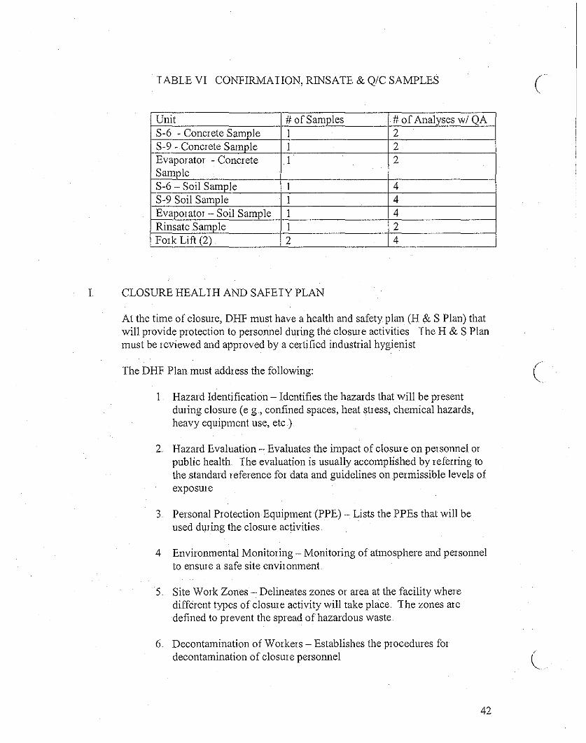
TABLE VI CONFIRMATION, RINSATE & Q/C SAMPLES
Unit # of Samples # of Analyses wi QAS-6 - Concrete Sample I 2S-9 - Concrete Sample I 2Evaporator - Concrete I 2SampleS-6 - Soil Sample I 4S-9 Soil Sample I 4Evaporator - Soil Sample 1 4Rinsate Sample 1 2Fork Lift (2) 2 4
L CLOSURE HEALTH AND SAFETY PLAN
At the time of closure, DHF must have a health and safety plan (H & S Plan) thatwill provide protection to personnel during the closure activities The H & S Planmust be reviewed and approved by a certified industrial hygienist
The DHF Plan must address the following:
I Hazard Identification - Identifies the hazards that will be presentduring closure (e g, confined spaces, heat stress, chemical hazards,heavy equipment use, etc.)
2. Hazard Evaluation - Evaluates the impact of closure on personnel orpublic health. The evaluation is usually accomplished by refelling tothe standard reference for data and guidelines on permissible levels ofexposure
3 Personal Protection Equipment (PPE) - Lists the PPEs that will beused during the closure activities.
4 Environmental Monitoring - Monitoring of atmosphere and personnelto ensure a safe site environment
5. Site Work Zones- Delineates zones or area at the facility wheredifferent types of closure activity will take place. The zones aredefined to prevent the spread of hazardous waste
6 Decontamination of Workers - Establishes the procedures fordecontamination of closure personnel
42
c
(

J
K
CLOSURE SCHEDULE
When DHF decides to close the facility, the owner or operator shall notify DTSCtheir intent of closure at least 90 days prior to the beginning of the closure planimplementation DISC may require the owner or operator to amend the closureplan that time.
The closure plan implementation must comply with the following closureschedule:
Wastes must be removed and structures/equipment decontaminatedwithin 90 days ofthe date that the facility stopped receiving hazardouswaste or the closure plan was approved, whichever is later
2. All closure activities must be completed within 180 days of the datethat the facility stopped receiving hazardous waste 01 the closure planwas approved whichever is later
CLOSURE CERTIFICATION REPORT
Afler all closure activities have been completed, a closure certification must besubmitted by DHF The certification must be submitted to DTSC by registeredmail within 60 days of completion of closure activity
The Closure Certification Report must include the following:
1 A certification by an independent professional engineer registered inCalifornia in accordance with Title 22, California Code ofRegulations, Section 66270 .11 (d)
2 Supervisory Personnel Description - Identify the person(s) orcompanies who were responsible for supervision of closure activitiesat the site, including transportation of waste and sample collection.
3 Summary of Closure Activities- The walls ofthe buildings, alltreatment units, storage areas, evaporator, forklifts will bedecontaminated per description mentioned above
4. Field Engineer Observation Report
5 Sampling Data Analysis - All sampling information such as samplinglocations, chain of custody, analytical results will be included
6. Discussion of Analytical Results
43

7 Manifests - Copies ofmanifests showing the disposition ofthe wasteinventory
8. Modification and Amendments to Closure Plan
9 Photographs
DHF facility also must keep and maintain the following documents at the facilityuntil the closure certification is approval
I Approved Closure Plan2 Copies of the independent Professional Enginem's field observation
reports3 Laboratory results of samples analyzed4. Quality assurance/quality control demonstrations5 Manifests6 Closure certification
SECTION X
CERTIFICATION (See Attachment AA-7)
44