davit lube procedure for 1995 bayliner 4788 pilothouse...
TRANSCRIPT
Davit Lube Procedure for 1995 Bayliner 4788 Pilothouse 4/10/05 Parts Needed:
• Superlube • Wood Shims* • Wood Blocks* • Crow Bar* • House Jack*
• Carpets to protect boat or similar
• 1 ½” deep socket wrench
• Cylinder Hohn* • Push pin
• Hammer • 7/16” open or box
wrench • C-Clip Pliers
*only needed in extreme cases WARNING: Part of this procedure requires at least 2 people, when removing and reattaching the davit arm. It is quite heavy once the gas springs are disconnected!
1. Ensure davit breaker is in OFF position. 2. Make note of which wire goes where on the motor. Disconnect both wires from the motor. Ensure they will snake
back through the davit arm freely on their own as you remove the davit arm. 3. Remove only the clips from the gas springs at the pedestal (Picture #10) 4. Remove only the C-Clip from the stationary clevis pin. You will need a pair of C-Clip pliers to do this (Picture #1) 5. Someone will now have to be ready to hold the weight of the davit arm. 6. Remove the T-handled clevis pin from the davit arm.
7. Remove the gas springs from the ball studs at the pedestal. You may need to tap them out with something if they have not been previously lubed.
8. Remove the stationary clevis pin from the davit arm. You will need a push pin to hammer it through until you are
able to pull it from the other side. There are 2 large nylocon(sp?) spacers between the arm and the pedestal that will fall out once you remove the stationary clevis pin (Picture #1)
9. Set the davit arm aside. Inspect the gas springs and ball studs on both the davit arm and pedestal. If they need
replacing, you can get them at: Service Plus Distributors in PA (215) 785-4466 Gas springs p/n: SPD-GS-6508, were $36 each in 2003, order 2 Ball studs p/n: SPD-BS-1005, were $1 each in 2003, order 4 Make sure the clips are included, if not, get them NOTE: The gas springs are specifically rated at a certain weight, so do not substitute just any gas spring. 10. Once the davit arm is off, the pedestal should look like Picture #2. You will need to remove the protective casing from the wires. Slide it off, it is tough getting the ends through. 11. Once the casing is off (Picture #3) put a 1 ½” deep socket on the bolt (Picture #4). Push the wire into the socket just enough to get a wrench on it. Do not push the wires too far down, you need to be able to get them back out. 12. Remove the nut from the post. 13. You may be able to pull the pedestal up and off of the post, but if the bushings are swollen you will need to pry it off. Let’s hope this is not the case and you can go to step #16 14. If you need to pry it, you will need a lot of wood shims, wood blocks and a crow bar, but we ended up using a
house jack because it was so tight.
15. Start at one point and work your way around the pedestal (Picture #5). Move a very small distance each time, using the wood shims and blocks to save your progress as you go. This could take hours and requires a lot of patience. Continue to circle around until you are able to remove the pedestal from the post.
16. Once removed you will see the post and 2 large spacers on top of the post or they may be stuck inside the
pedestal (Picture #6 & #7) 17. There are three bushings inside the pedestal: Inner Lower: ID 3.875, OD 4.584 Outer Lower: ID 4.587, OD 5.299 Upper: ID 3.875, OD 5.299 18. Turn the pedestal upside down and remove the inner lower bushing (Picture #8 & #9). If it is tight you will need
to use a similar technique as when you took the pedestal off the post. Just keep going around in circles, pulling up on the bushing.
19. According to US Marine, the bushings should be relieved to a distance of 10-12 mils between each of them and the
post. This can be done with a cylinder hohn, although we did not have much success with this, the tool kept breaking. We instead ended up using the precision method of wet sanding them by hand until they fit comfortably within each other. We started out with 180 wet sandpaper and went down to 400 when we had the right dimensions. Also, ensure that the 2 spacers which sit on top of the post fit inside the bushings well, if not you may need to relieve the OD on them as well. I am sure they are not 10-12 mils apart, but the davit works fine, so who cares. Be careful not to relieve them too much as they need to remain in place when you reassemble the pedestal. If the bushings are in really bad shape, you can get replacements from US Marine, speak to Ken Naff in Everett at (360) 435-5571. Also, Ken told me that you can have a new roller assembly retrofitted in the pedestal from US Marine, he said that it makes a big difference in operation, but it is expensive.
20. Ensure all bushings spacers, pedestal and post are cleaned very well before reassembling them.

21. Once you have all bushings the way you want them, apply generous amounts of Superlube to them (never use a petroleum based lubricant, it causes the nylocon(sp?) bushings to swell). Re-insert them into the pedestal the way they came out.
22. Apply generous amounts of Superlube to the post and the 2 spacers on top and to the post. 23. Place the pedestal back onto the post. It should slide on and move freely back and forth. 24. Once you’re satisfied with the movement, put the nut back on, make sure the wires are through the top. Do not
tighten the nut, its only purpose is to keep the pedestal from rising up. If it is too tight, the pedestal will not turn well. Get it down as far as you can while still having fluid movement of the pedestal.
25. Pull the wires all the way out and put the casing back on. 26. Put some Superlube on the spacers, both clevis pins and the ball studs. 27. Someone will now have to pick up the davit arm and hold it in place, while another will insert the stationary clevis
pin, along with the spacers. Spacers go on both sides in between the davit and the pedestal. Don’t worry about the clip for now.
28. Make sure the wires do not get crushed when you reattach the arm. Get them into the arm then you can position
them correctly once the arm is secure. 29. Lock in place the gas springs onto the ball studs. Don’t worry about the clips for now. 30. Insert the T-handled clevis pin 31. Now that the davit arm is reattached, go ahead and attach the C-Clip to the stationary clevis pin using the C-Clip
pliers and attach the clips to the gas springs around the ball studs (Picture #10) 32. Put Superlube on the gas springs to prevent corrosion.
33. Feed the wires over the bar on the lower end of the davit arm and then snake through to arm to the motor. Reattach the wires.
At the end of this document is the schematic that was faxed to me from US Marine.
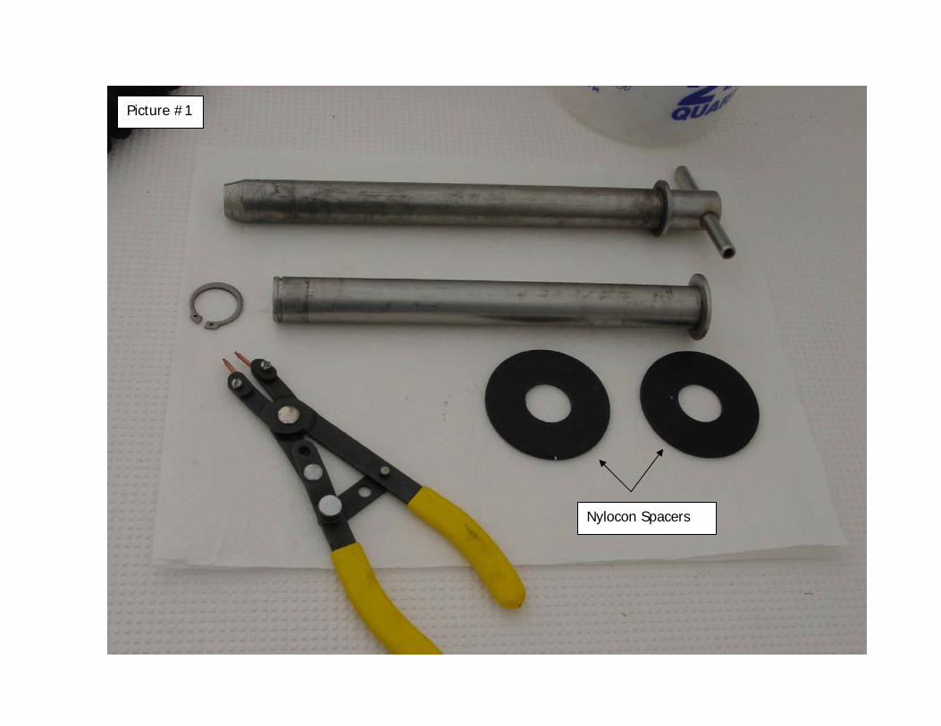
Picture #1
Nylocon Spacers
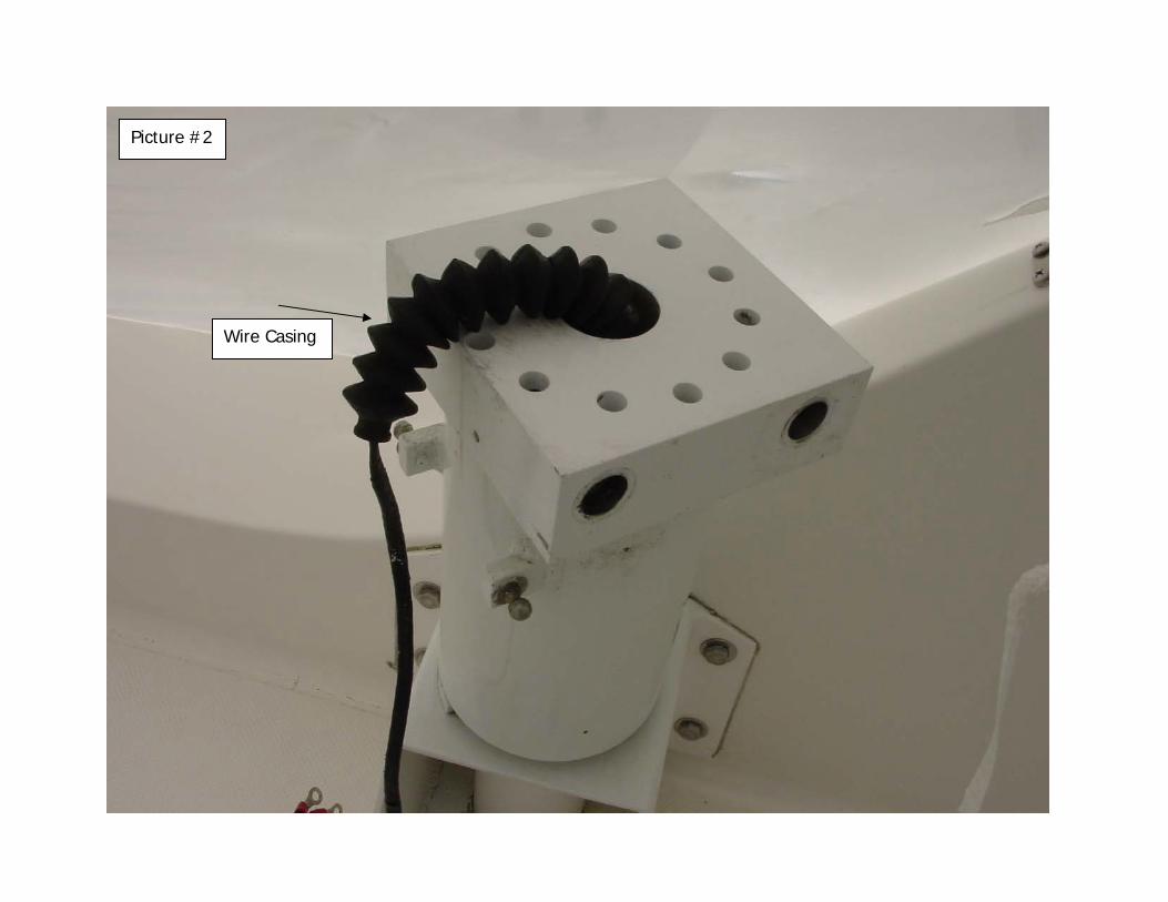
Picture #2
Wire Casing

Picture #3
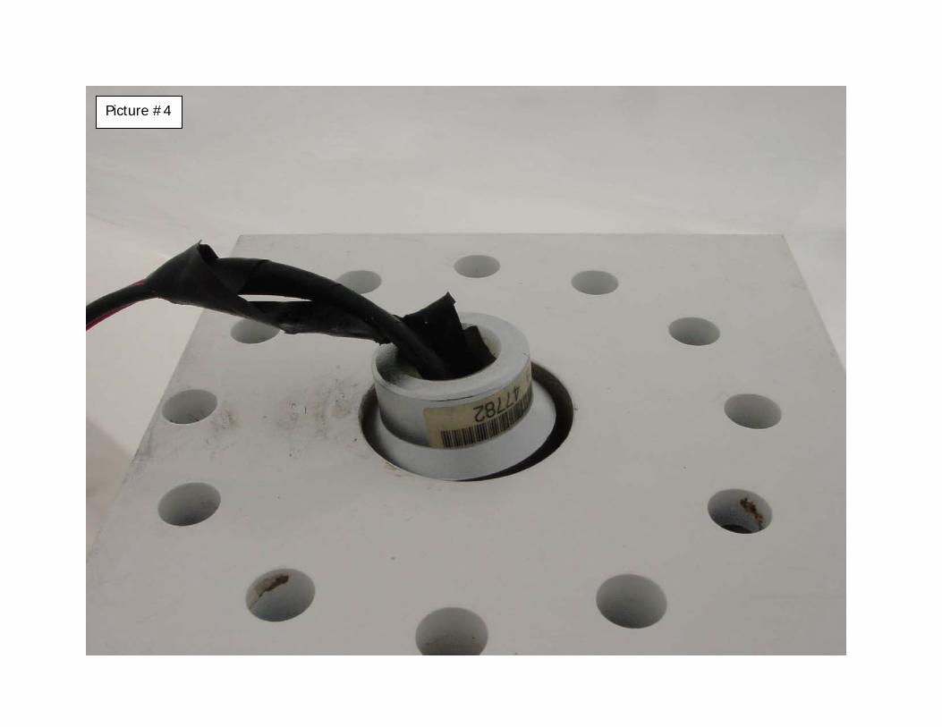
Picture #4

Picture #5

Picture #6

Picture #7
2 Nylocon Spacers
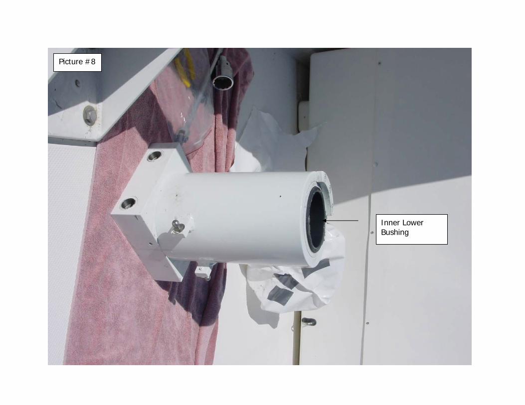
Picture #8
Inner Lower Bushing

Picture #9
Upper Bushing
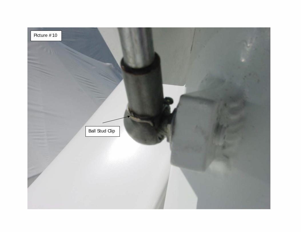
Picture #10
Ball Stud Clip
