day 2 1300 explosive products lm bf v1.ppt
TRANSCRIPT

Explosive ProductspLawrence J. Mirabelli

Choosing Optimum Explosive Type
For Main Explosive Charge and/or Primer make-up Critical diameterDensitySensitivitySensitivitySensitivenessWater resistanceDetonation elocitDetonation velocityDetonation pressure / Borehole pressureEnergyStorage, Transportation and Loading/HandlingValue

Explosive Types – Main Explosive Charge
Bulk ExplosivesBlasting Agent 1 5 D (not detonator sensitive)Blasting Agent, 1.5 D (not detonator sensitive)
• ANFO• Heavy ANFO Blend (ANFO with 5% to 50% Pumpable Explosive or Non Explosive
Matrix))– Water gel– Emulsion
• Repumpable Emulsion ANFO Blend (Repumpable Explosive Matrix with 0% to 50% ANFO)ANFO)
– Water gel– Emulsion (available with chemical sensitization/field density adjustment)
• Repumpable Explosive Matrix– Water gel– Emulsion (available with chemical sensitization/field density adjustment and/or
viscosity adjustment)

Bulk ANFO
96% Ammonium Nitrate and 6% Fuel Oil.Physical Properties
Bulk poured density: 0.82 - 0.85 g/cm3 (dependent on AN source)Loading density: 0.85 to +1.00 g/cm3 (dependent on: storage conditions, the method of handling and the number of times the AN used to mix or mixedmethod of handling and the number of times the AN used to mix or mixed ANFO is handled before actual loading, loading equipment used.)Water resistance: none
Detonation Properties1.5D Blasting AgentAWS = 3.7 MJ/kg (401 Kcal/lb)RWS = 100RBS = 100 to 115RBS = 100 to 115VoD = 2,500 to 4,500 m/s (8,200 to 14,700 ft/s)High gas (heave) energy potential

Energy and Sensitivityvariation of ANFO
80
90
100
Sensitivity ty80
60
70
ut (%
)
Sen
sitiv
it
40
50
Ener
gy O
utpu Energy
crea
sing
20
30
E
Inc
Under fueledNitrous Oxide
Over fueledCarbon Monoxide
Oxygen balanced Steam and Nitrogen
0
10
0 2 4 6 8 10 12Fuel oil (%)Fuel oil (%)

Effect of Confinement on ANFO
16000 Confined
10000
12000
14000
)
6000
8000
10000
VoD
(ft/s
)
ANFO (density = 0.8 g/cc)
Unconfined
2000
4000
00 5 10 15
Charge Diameter (in)

Decision Points for Bulk ANFO
AdvantagesSomewhat easy to manufacture correctly. Fairly simple equipment required.Can be mixed at borehole.Low densityHigh EnergyCost effectiveCost effective
DisadvantagesLow densityNo water resistance.No water resistance.Fume generation if used improperly or if under or over-fueled.Variable Energy output if used improperly or if under or over-fueled.Requires additional materials and equipment if water is present in holes.
• Liners• Dewatering Pumps

Heavy ANFO Blends
Blend of ANFO and un-sensitized water gel or emulsion matrix or ANFO d iti d t l l i l i t i ( t i tand sensitized water gel or emulsion explosive matrix. (contain greater
than 50% ANFO)Physical Properties
Bulk density range is 0.95 to 1.35 g/cm3 (dependent of ANFO percentage inBulk density range is 0.95 to 1.35 g/cm3 (dependent of ANFO percentage in blend)Water resistance increases with the increasing emulsion content in the blendHigher water resistance than ANFO
Detonation Properties1.5D Blasting Agent.Critical Diameter decreases with increasing ANFO content.VoD increases with decreasing ANFO content (13 800 to 17 700 ft/sec)VoD increases with decreasing ANFO content. (13,800 to 17,700 ft/sec)AWS decreases as ANFO percentage decreases in blend.RBS increases as ANFO percentage increases in blend.

Density vs % Emulsion in Heavy ANFO
1.4
1.5 Auger Pump
1.2
1.3
1.4
(g/c
c)
Unsensitized
1
1.1
Dens
ity ( Unsensitized
Sensitized
0.8
0.9Heavy ANFO
0 20 40 60 80 100
Percent Emulsion

Water Resistance vs % Emulsion in Heavy ANFOy
100
nce
Auger Pump
50
r Re
sist
an
0
Wat
er Heavy ANFO
0 20 40 60 80 100
Percent Emulsion

Critical Diameter vs % Emulsion in Heavy ANFOy
200
250
r (m
m)
100
150
Dia
met
er 8 inch
5 inch
0
50
Crit
ical
Heavy ANFO (using unsensitized emulsion matrix)
0 10 20 30 40 50 60
Percent Emulsion
Decision Points for Heavy ANFO Blends
AdvantagesMixed at boreholeDensity can be varied for applicationVoD and Energy (AWS) can be varied for applicationHigh RBS EnergyMore water resistant than ANFOMore water resistant than ANFO.
DisadvantagesMust use emulsion compatible AN for ANFO used in the Heavy ANFO Blend.Requires more specialized equipment than ANFO.Requires more specialized equipment than ANFO.Field Quality Control is necessity. (Particularly with unsensitized matrix)Variation in Density, Critical Diameter, VoD, and Energy if blended inconsistently.R i dditi l t i l d i t if t i t i h lRequires additional materials and equipment if water is present in holes.
• Liners• Dewatering Pumps

PumpableBulk Emulsion ANFO Blends
• Blend of water gel or emulsion explosive matrix and ANFO or field iti d t l l i t i d ANFO ( t i t thsensitized water gel or emulsion matrix and ANFO. (contain greater than
60% emulsion or water gel matrix)Physical Properties
Bulk density range is 1.28 to 1.32 g/cm3 (dependent on Water gel or EmulsionBulk density range is 1.28 to 1.32 g/cm3 (dependent on Water gel or Emulsion matrix percentage in blend)Water resistance increases with the increasing emulsion content in the blendGood water resistance compared to Heavy ANFO Blends
Detonation Properties1.5D Blasting Agent.Critical Diameter decreases with increasing water gel or emulsion matrix content.content.VoD increases with increasing water gel or emulsion matrix content. (14,800 to 19,000 ft/s)AWS increases with ANFO percentage in blend.RBS i ith ANFO t i bl dRBS increases with ANFO percentage in blend.

Decision Points for Pumpable Emulsion ANFO Blendsp
AdvantagesMixed at boreholeDensity can be varied for application. (even further where field chemical sensitization is used).VoD and Energy (AWS) can be varied for applicationHigh RBS Energyg gyMore water resistant than Heavy ANFO Blends.Can be pumped directly into holes where water is present, Does not require additional materials and equipment.
Di d tDisadvantagesMust use emulsion compatible AN for ANFO used in the Pumpable Emulsion ANFO Blend.Requires more specialized equipment than Heavy ANFO Blends.q p q p yField Quality Control is necessity. (Particularly with unsensitized matrix)Variation in Density, Critical Diameter, VoD, and Energy if blended inconsistently

PumpableBulk Emulsion Explosivesp
• Pumpable Emulsion Explosive or field sensitized Emulsion matrix. Physical Properties
Bulk density range is 1.20 to 1.35 g/cm3 (emulsion explosive)Bulk density range is 0.85 to 1.35 g/cm3 (field sensitized emulsion matrix)C l l t d t dditiColor related to additives.Excellent Water resistance.
Detonation Properties1 5D Blasting Agent1.5D Blasting Agent.Properties vary with chemical composition - can be tailor made to application.Critical Diameter decreases with decreasing density.VoD dependent on hole diameter & density (14,700 – 19,700 ft/s),AWS dependent upon emulsion composition.RBS increases with increasing density.

Decision Points for Pumpable Emulsion Explosivesp p
AdvantagesCan be field sensitized at borehole. (Only where chemical sensitization is available )available.)Density can be varied for application. (Only where chemical sensitization is available.)Density can be varied within individual borehole loads. (Only where loading t h l i il bl )technology is available.)VoD and Energy (AWS) can be varied for applicationVariable RBS Energy.Excellent water resistance No need for additional equipmentExcellent water resistance. No need for additional equipment.Viscosity can be modified to increase performance, increase flow properties and reduce product migration.
DisadvantagesRequires more specialized equipment than Heavy ANFO.Field Quality Control is necessity. (Only where unsensitized matrix is used)Variation in Density, Critical Diameter, VoD, and Energy where sensitized inconsistently.inconsistently.

Bulk Explosive – Value Decision
Water ResistanceCost/lbDensity
Ease of useSleep timeChemical Stabilityy
VoDRBS
Shock Energy
y
RWSHeave Energy
No. of Blastholes
ANFO Pumped EMULSIONHeavy ANFOBlends
PumpedEmulsion ANFO
BlendsBlends
Explosive Types – Main Explosive Charge
Package ExplosiveExplosive 1 1 D (detonator sensitive)Explosive, 1.1 D (detonator sensitive)
• Dynamite• Emulsion• Water GelWater Gel
Blasting Agent, 1.5 D (not detonator sensitive) • ANFO, ANFO WR• Water gel• Water gel• Emulsion

Packaged Explosives
Includes Dynamites, Emulsion and Water Gel explosivesPhysical Properties
Package density range• Dynamites - 1.01 to 1.54 g/cm3 (available in paper convolute or tube shells only)• Emulsions & Water gels - 1.05 to 1.28 g/cm3 (available in paper convolute or tubes shells,
plastic chubs or woven shot bags depending on product, grade and/ explosiveplastic chubs or woven shot bags depending on product, grade and/ explosive classification.
Good to Excellent Water resistance (depending on product type and grade) Detonation Properties
Dynamites 1.1D; Water gels and emulsions 1.1D or 1.5D depending on product type and grade.VoD: Dynamites 5,000 to 20,000 ft/sec; Water Gels and Emulsions 13,000 to 21 000 ft/sec21,000 ft/sec.RWS: Dynamites 0.96 to 1.21 ; Water Gels & Emulsions 0.84 to 1.14RBS: Dynamites 1.30 to 2.31 ; Water Gels & Emulsions 1.18 to 1.38
Decision Points for Packaged Explosivesg p
AdvantagesFixed configuration
• Maximum control of explosive weight per deck per hole• Maximum control of explosive weight per deck per hole• Maximum control of explosive load factor (lbs/ft).
Dynamite provides high densities, RWS, RBS, Pressure resistance and sensitivity. It is very effective in demanding quarry applications.G d t ll t t i t d di dGood to excellent water resistance depending on grade.No mechanical equipment necessary for loading.
DisadvantagesLabor intensiveLabor intensiveDisposal of package materials (1.1 D only)Packaged explosives cannot completely fill the blasthole. Some energy is lost converting water in the blasthole to steam during the gy g gdetonation, reducing available energy.For package diameter 4 inch and larger the 1st package requires lowering onto primer in dry boreholes. Emulsion packages need to be lowered into dry boreholes deeper than 100 ft.

Explosive Types – For use in Primer make-up
Package ExplosiveExplosive 1 1 D (detonator sensitive)Explosive, 1.1 D (detonator sensitive)
• Dynamite• Emulsion• Cast BoostersCast Boosters

Explosive Primer• A primer is defined as a high explosive with a detonator properly
attached• The purpose of a primer is to provide sufficient explosive energy to• The purpose of a primer is to provide sufficient explosive energy to
initiate detonation of the main explosive charge.The performance of the main explosive charge can be influenced by:
the choice of primer,p ,the number of primers used in a column,the distance between the number of primers and the timing of the initiation of the primers .
Primer selection should be based on:Choice of main explosiveCompositionShapeShape
• Diameter that best matches the charge or hole diameter. Particularly with 1.5D Blasting Agents.

Explosive Primer
There is a distance from the point of initiation in the explosive column, that is specific to every explosive, over which the detonation reactionthat is specific to every explosive, over which the detonation reaction travels before it reaches its steady state. This is the “Run-up” distance.
The “Run-up distance is reduced with increasing size and density and VoD primers
1.5D Blasting Agents have much longer run up distances than 1.1D Explosive materials. Some 1.5D Blasting Agents “Run-up” distance can extend 1 - 3 hole di t l th if i h l d it d V D i d i ddiameter lengths if a primer has low density and VoD or is undersized.Some 1.5D Blasting Agents steady state VoD can be overdriven for distances of at most 1 - 3 hole diameters if a very efficient and over sized primer is usedprimer is used.
“Run-up” distance and time
1.1 D Explosives
1.5 D Blasting Agents
Increasing time from detonation

Initiation SystemsBaron Fidler

Choosing Optimum Type
Initiation SystemType signalTiming options
• Fixed– Number of delay periods
• Programmability
Accuracy/PrecisionStorage, Transportation and Loading/HandlingValue

Various Types of Initiation Systems
Detonating CordNonelectricNonelectricElectricElectronic

Explosive Types – Initiation System
NonelectricMiniaturized Detonating Cord / NONEL
• Low core load detonating cord• Millisecond delay period detonators – surface and in-hole
NONEL• Shock tube lead• Millisecond delay period detonators – surface and in-hole
El t iElectricCopper leg wiresMillisecond delay period detonatorsBl ti E i tBlasting Equipment
• Standard Capacitor Discharge Blasting Machine• Sequential Capacitor Discharge Blasting Machine
Detonating Cord
When to Choose When Not to ChooseExtreme Loading ConditionsMultiple Priming RequirementsClosed Loop / Redundancy
Small Diameter Blast Holes• explosive damage or disruption will result
Sensitive Explosive• Premature initiation will result
Safety of Full Initiation• Tunnel/Shaft• Cast Blasting• Critical Situations
Explosive can be DesensitizeNoise Sensitive Environment
• Critical Situations
Contamination• Salt Mines• Chemical Stone• Limestone

Nonelectric Initiation SystemsShock tube systemsy
When to Choose When Not to ChooseStray Current HazardsStatic Electricity Hazards
• Wind
Extreme Loading ConditionsMechanical or Electrical Check is a MustM tti C i Bl t• Low humidity
• Plastic liners
Small Diameter HolesTiming Flexibility
Matting or Covering a Blast
Timing FlexibilityInventory ConcernsSimple Use System
Nonelectic Shock Tube
•External layer for abrasion resistance and UV protection
•Middle layer for tensile strength, elongation and chemical resistance
•Inner Layer reliably holds the reactive mixture in place
Shock tube has a small diameter 3 layer plastic t b i t ll t d ith d f titube internally coated with one pound of reactive material per 100,000 feet. This tube transmits a low energy signal form the point of initiation to the delay cap at approximately 2.100 m/second (6 500 ft/ ) Th d t ti i t i d b(6,500 ft/sec). The detonation is sustained by such a small quantity of reactive material that the outer surface of the tube remains intact during functioning.

Various Packaging, similar function & application.

Surface Connectors
Makes hole-to-hole connections.Sequences the shotHole-to-hole timing
Low energy detonator.Combined with plastic connector body reduces shrapnel hazard
M l i l h k b iMultiple shock tube capacity.Contains a detonator
Use caution when vehicles are “on the shot”the shot”.
Connector Block Comparison
Always check with your manufacturer.
Different types of connectors have different tube capacities.Some connectors requireSome connectors require covering to prevent shrapnel.

Product Selection
Double Ended Delay Detonators
MS Units & Surface Delays
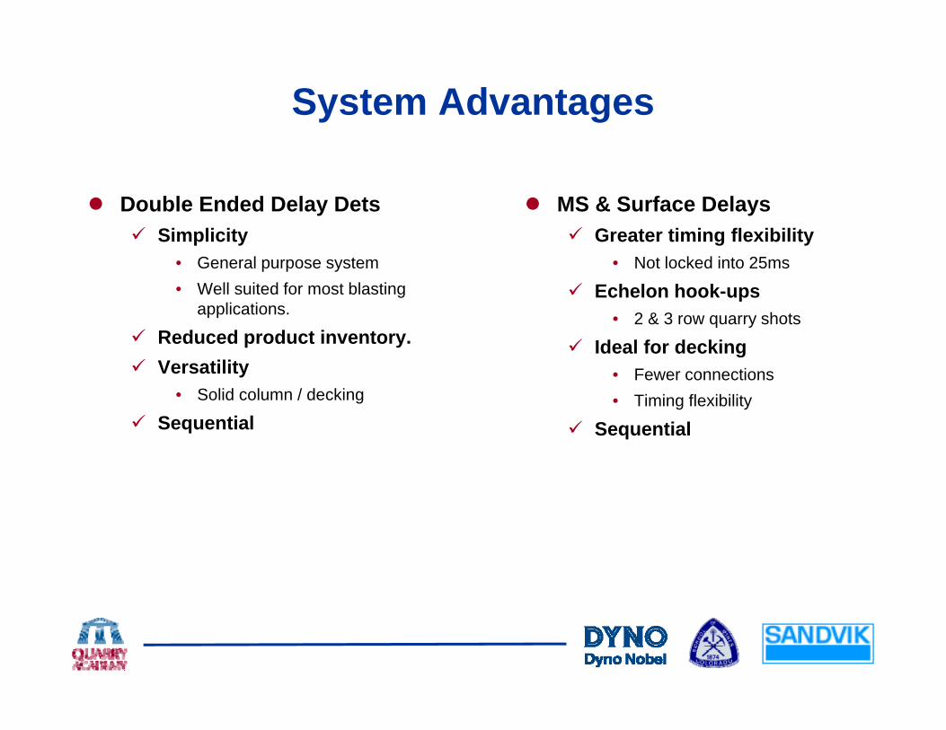
System Advantages
Double Ended Delay Dets MS & Surface DelaysSimplicity
• General purpose system• Well suited for most blasting
applications.
Greater timing flexibility• Not locked into 25ms
Echelon hook-ups• 2 & 3 row quarry shots
Reduced product inventory.Versatility
• Solid column / decking
• 2 & 3 row quarry shots
Ideal for decking• Fewer connections• Timing flexibility
Sequential Sequential

Redundant Surface Delays
Backup surface delays provide two paths of initiation for each hole.hole.Guards against the hazards associated misfired shots. Redundancy improves delayRedundancy improves delay timing accuracy.Always check the surface connections.

Electric Initiation Systems
When to Choose When Not to ChooseCircuit Testing RequiredMatting or Covering BlastsContamination Concern
Stray Current PotentialStatic Electricity hazardsRadio Frequency HazardsContamination Concern
• Shock tube in Muck• Easy to Recycle
Radio Frequency Hazards

Electronic Initiation SystemsA variety of systems are available.y y

Explosive Types – Initiation System
Electronic Copper leg wiresField programmable precision delay detonatorsNonexplosive accessories
• Wire, connectors, controllers etcComputer testing, programming and blasting equipment.
Branch
Row Controllers
hBlast Key
Extender Cable
Controller
Tagger
BenchController
Key
End Plug
Blast Cradle
Detonators

Generic Detonator Construction
Shock Tube WiredShockTube
Shock Tube Electric
Anti-Static
DelayM d l
Cup
Igniter(B id )
Anti-StaticCup
Igniter
Module
Capacitor
(Bridge)
DelayElement(s)
g
BaseCharge
PrimerCharge
BaseCharge
PrimerCharge
g
Electronic DelayPyrotechnic Delay

System Understanding is Essential
Each manufactures system is different.yProgrammable systems rely on direct communication with detonators through handheld loggers & blasting machines.
• Blasting machines & loggers are different• Blasting machines & loggers are different.• Each have unique communication protocols & firing codes.
Detonator construction varies.• All have stored energy source to power unique timing and firing
circuits.

Understanding Electronic Detonators
Handheld test & programming units check detonator circuitry prior to final hook-up.The blasting machine does the final system level continuity check and detonates the shot.Some detonators have multiple integrated circuits and capacitors built into the “electronics package”.Detonators may have specific operational pressure and temperatureDetonators may have specific operational pressure and temperature ranges.
The delay package must be able to “survive the shot”.Wi t l t d h k illWire style, connectors and hook-up will vary.

The Challenges of Electronic Systems
Added ComplexityTraining Requirements
Blaster certification required for many systems.Environmental LimitationsEnvironmental Limitations
Temperature, transient pressures & shock.System CostEquipment
Must work in a rugged environment. Must be maintained.Dumb IntelligenceDumb Intelligence
Program precisely the wrong timing.

Opportunities of Electronic Systems
Added Blast Control & Improved FlexibilityElectronics give blasters the ability program shots with precise and accurate delay times.Combined with frequency waveform analysis electronics can reduce peak particle velocities and increase frequencies.
Improved EconomicsReduced production costs can be achieved through improved fragmentation & pattern expansion.
Education of BlastersEducation of BlastersAttention to all blast design parameters is required to achieve the maximum results from electronics.
Communication with the SystemyBlast design & system interrogation
Information/Control

Electronic Challenges / Opportunities
Added Complexity Added blast ControlTraining RequirementsEnvironmental Limits
Temp/Pressure/Shock
M lti l U I t f
Education of BlastersUnderstand Dynamics
Better ControlMultiple User InterfacesDumb Intelligence System CostsCommunication
More Accurate TimingImproved FlexibilityImproved EconomicsCommunication
Equipment
Improved EconomicsCommunication with the SystemInformation/Control

Electronic Initiation Systemsy
Choose the Right Systemg yField Programmable or Factory ProgrammedField Programmable or Factory ProgrammedPrecision and AccuracyPrecision and AccuracySecurity LevelSecurity LevelBlast Management CapabilityBlast Management CapabilityComplexityComplexityComplexityComplexityTrainingTrainingInvestmentInvestment
What questions do you have?What questions do you have?

dwww.quarryacademy.com