day01 01 software requirement concepts
TRANSCRIPT

1
2
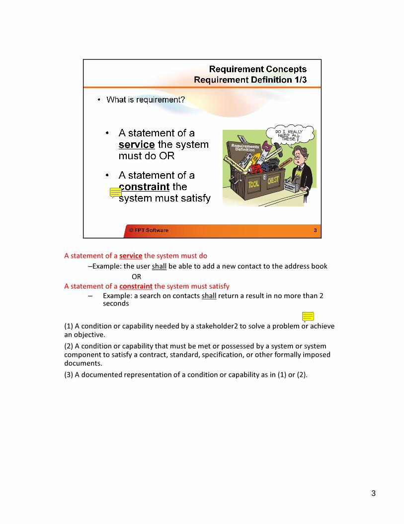
A statement of a service the system must do
–Example: the user shall be able to add a new contact to the address book–Example: the user shall be able to add a new contact to the address book
OR
A statement of a constraint the system must satisfy
– Example: a search on contacts shall return a result in no more than 2 seconds
(1) A condition or capability needed by a stakeholder2 to solve a problem or achieve an objective.
(2) A condition or capability that must be met or possessed by a system or system component to satisfy a contract, standard, specification, or other formally imposed documents.
(3) A documented representation of a condition or capability as in (1) or (2).
3
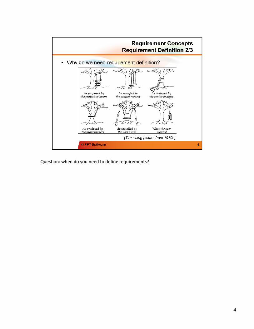
Question: when do you need to define requirements?Question: when do you need to define requirements?
4
5
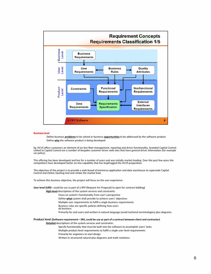
Business level
Define business problems to be solved or business opportunities to be addressed by the software productDefine business problems to be solved or business opportunities to be addressed by the software product
Define why the software product is being developed
Eg. HCVS offers customers an element of on-line fleet management, reporting and driver functionality, branded Capital Control. Linked to Capital Control are a number of bespoke customer driver web sites that have general driver information (for examplecar policy).
This offering has been developed and live for a number of years and was initially market leading. Over the past few years thecompetitors have developed better on-line capability that has leapfrogged the HCVS proposition.
This objective of the project is to provide a web-based eCommerce application and data warehouse to supersede Capital Control and Online Quoting tool and retake the market lead.
To achieve this business objective, the project will focus on the user experience.
User level (URD - could be use as part of a RFP (Request For Proposal) to open for contract bidding)
High-level descriptions of the system services and constraints
Focus on system’s functionality from user’s perspective
Define what system shall provide to achieve users’ objectives
Multiple user requirements to fulfill a single business requirements
Business rules are specific policies defining how users do business
Primarily for end-users and written in natural language (avoid technical terminologies) plus diagrams
Product level (Software requirement – SRS, could be use as part of a contract between client and contractor)
Detailed descriptions of the system services and constraints
Specify functionality that must be built into the software to accomplish users’ tasks
Multiple product-level requirements to fulfill a single user-level requirements
Primarily for engineers to start design
Written in structured natural plus diagrams and math notations
6
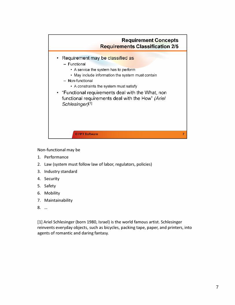
Non-functional may beNon-functional may be
1. Performance
2. Law (system must follow law of labor, regulators, policies)
3. Industry standard
4. Security
5. Safety
6. Mobility
7. Maintainability
8. …
[1] Ariel Schlesinger (born 1980, Israel) is the world famous artist. Schlesinger
reinvents everyday objects, such as bicycles, packing tape, paper, and printers, into
agents of romantic and daring fantasy.
7
8
9
10
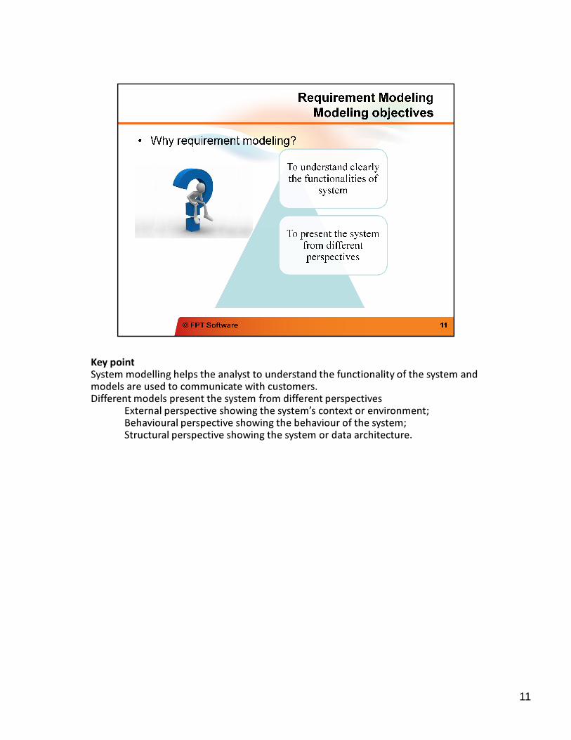
Key point
System modelling helps the analyst to understand the functionality of the system and System modelling helps the analyst to understand the functionality of the system and models are used to communicate with customers.Different models present the system from different perspectives
External perspective showing the system’s context or environment;Behavioural perspective showing the behaviour of the system;Structural perspective showing the system or data architecture.
11
12
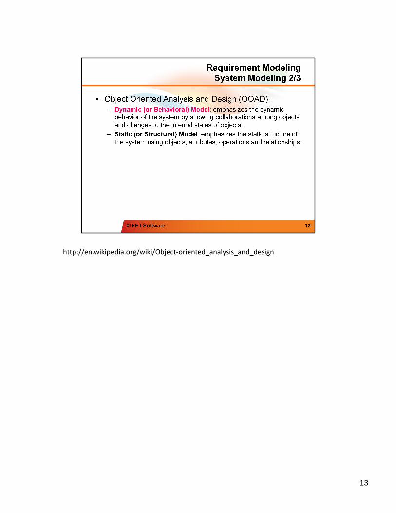
http://en.wikipedia.org/wiki/Object-oriented_analysis_and_designhttp://en.wikipedia.org/wiki/Object-oriented_analysis_and_design
13
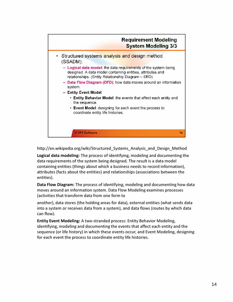
http://en.wikipedia.org/wiki/Structured_Systems_Analysis_and_Design_Methodhttp://en.wikipedia.org/wiki/Structured_Systems_Analysis_and_Design_Method
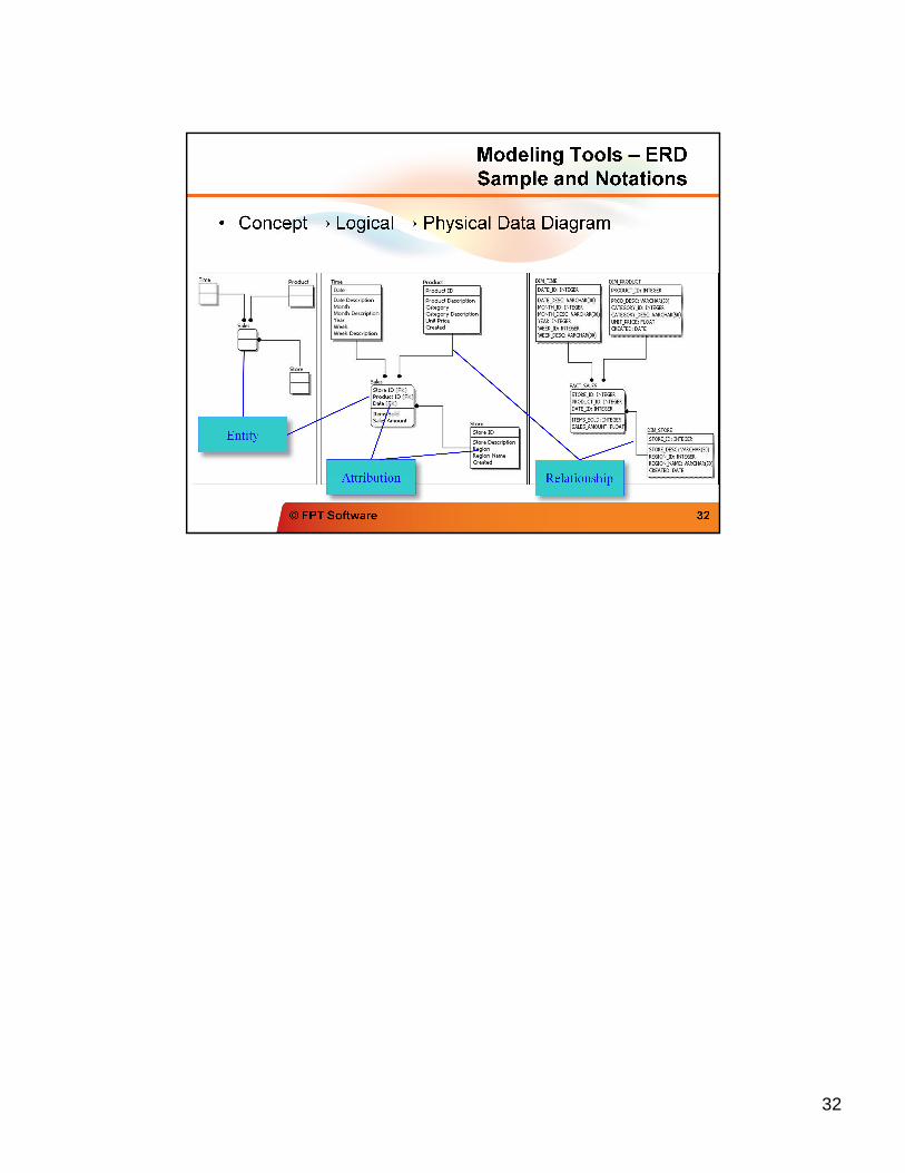
Logical data modeling: The process of identifying, modeling and documenting the
data requirements of the system being designed. The result is a data model
containing entities (things about which a business needs to record information),
attributes (facts about the entities) and relationships (associations between the
entities).
Data Flow Diagram: The process of identifying, modeling and documenting how data
moves around an information system. Data Flow Modeling examines processes
(activities that transform data from one form to
another), data stores (the holding areas for data), external entities (what sends data
into a system or receives data from a system), and data flows (routes by which data
can flow).
Entity Event Modeling: A two-stranded process: Entity Behavior Modeling,
identifying, modeling and documenting the events that affect each entity and the
sequence (or life history) in which these events occur, and Event Modeling, designing
for each event the process to coordinate entity life histories.
14
15
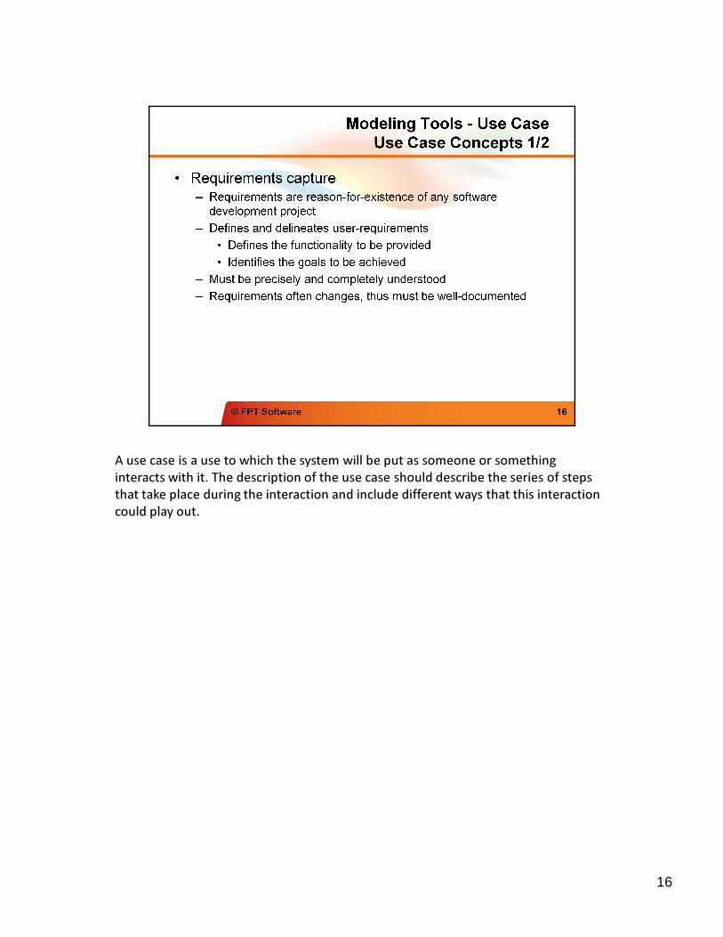
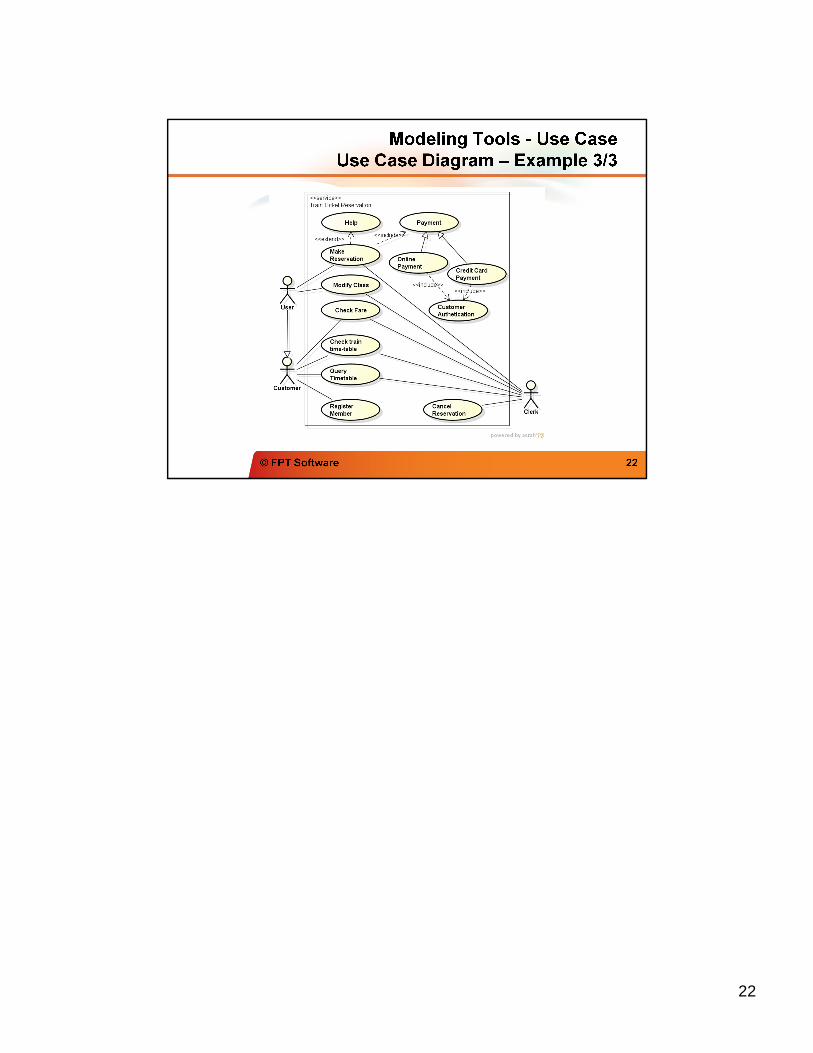
A use case is a use to which the system will be put as someone or something
interacts with it. The description of the use case should describe the series of steps
A use case is a use to which the system will be put as someone or something
interacts with it. The description of the use case should describe the series of steps
that take place during the interaction and include different ways that this interaction
could play out.
16
17
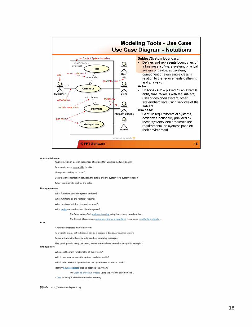
Use case definition
An abstraction of a set of sequences of actions that yields some functionality
Represents some user-visible function.
Always initiated by an “actor”
Describes the interaction between the actors and the system for a system function
Achieves a discrete goal for the actor
Finding use cases
What functions does the system perform?
What functions do the “actors” require?
What input/output does the system need?
What verbs are used to describe the system?
The Reservation Clerk makes a booking using the system, based on the...
The Airport Manager can make an entry for a new flight. He can also modify flight details ...
Actor
A role that interacts with the system
Represents a role, not individuals can be a person, a device, or another system
Communicate with the system by sending, receiving messages
May participate in many use cases; a use case may have several actors participating in it
Finding actors
Who uses the main functionality of the system?
Which hardware devices the system needs to handle?
Which other external systems does the system need to interact with?
Identify nouns/subjects used to describe the system
The Clerk do checkout process using the system, based on the...
A user must login in order to save his itinerary
[1] Refer: http://www.uml-diagrams.org
18
19
Use case definition
An abstraction of a set of sequences of actions that yields some functionality
Represents some user-visible function.
Always initiated by an “actor”
Describes the interaction between the actors and the system for a system function
Achieves a discrete goal for the actor
Finding use cases
What functions does the system perform?
What functions do the “actors” require?
What input/output does the system need?
What verbs are used to describe the system?
The Reservation Clerk makes a booking using the system, based on the...
The Airport Manager can make an entry for a new flight. He can also modify flight details ...
Actor
A role that interacts with the system
Represents a role, not individuals
can be a person, a device, or another system
Communicate with the system by sending, receiving messages
May participate in many use cases; a use case may have several actors participating in it
Finding actors
Who uses the main functionality of the system?
Which hardware devices the system needs to handle?
Which other external systems does the system need to interact with?
Identify nouns/subjects used to describe the system
The Reservation Clerk makes a booking using the system, based on the...
A user must login in order to save his itinerary
20
21
22
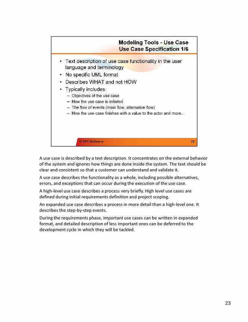
A use case is described by a text description. It concentrates on the external behavior
of the system and ignores how things are done inside the system. The text should be
A use case is described by a text description. It concentrates on the external behavior
of the system and ignores how things are done inside the system. The text should be
clear and consistent so that a customer can understand and validate it.
A use case describes the functionality as a whole, including possible alternatives,
errors, and exceptions that can occur during the execution of the use case.
A high-level use case describes a process very briefly. High level use cases are
defined during initial requirements definition and project scoping.
An expanded use case describes a process in more detail than a high-level one. It
describes the step-by-step events.
During the requirements phase, important use cases can be written in expanded
format, and detailed description of less important ones can be deferred to the
development cycle in which they will be tackled.
23
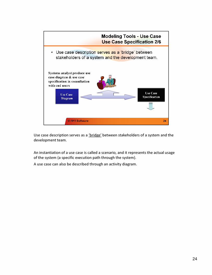
Use case description serves as a ‘bridge’ between stakeholders of a system and the
development team.
Use case description serves as a ‘bridge’ between stakeholders of a system and the
development team.
An instantiation of a use case is called a scenario, and it represents the actual usage
of the system (a specific execution path through the system).
A use case can also be described through an activity diagram.
24
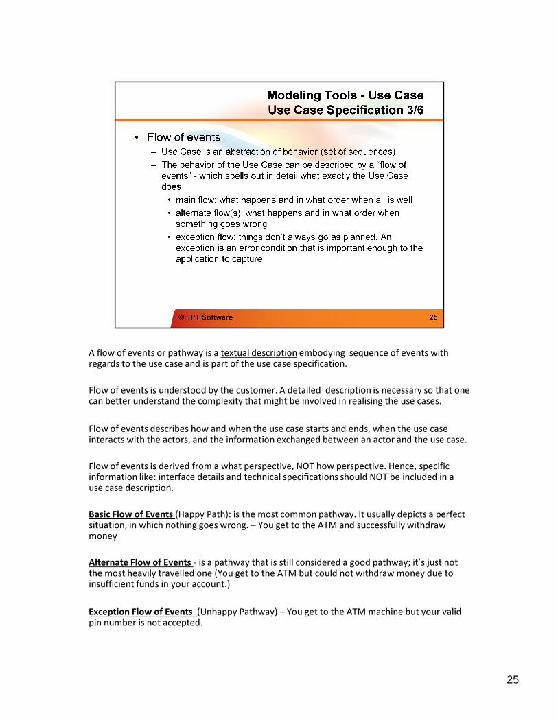
A flow of events or pathway is a textual description embodying sequence of events with regards to the use case and is part of the use case specification.regards to the use case and is part of the use case specification.
Flow of events is understood by the customer. A detailed description is necessary so that one can better understand the complexity that might be involved in realising the use cases.
Flow of events describes how and when the use case starts and ends, when the use case interacts with the actors, and the information exchanged between an actor and the use case.
Flow of events is derived from a what perspective, NOT how perspective. Hence, specific information like: interface details and technical specifications should NOT be included in a use case description.
Basic Flow of Events (Happy Path): is the most common pathway. It usually depicts a perfect situation, in which nothing goes wrong. – You get to the ATM and successfully withdraw money
Alternate Flow of Events - is a pathway that is still considered a good pathway; it’s just not the most heavily travelled one (You get to the ATM but could not withdraw money due to insufficient funds in your account.)
Exception Flow of Events (Unhappy Pathway) – You get to the ATM machine but your valid pin number is not accepted.
25
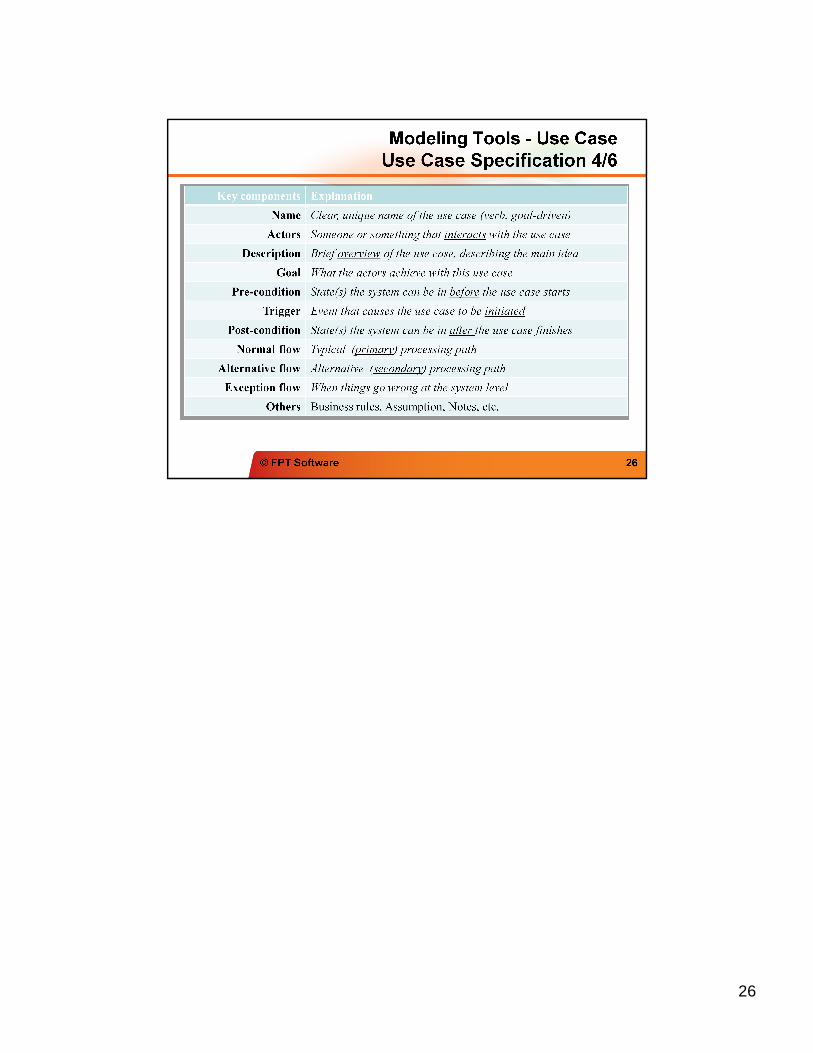
26
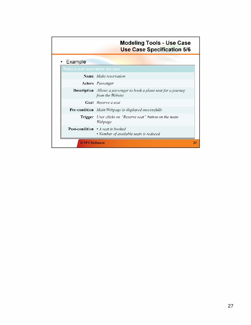
27
Qualities of a Good Use Case
The following guidelines have proven useful in producing tight, easy-to-understand use cases in a variety of contexts:
Use active voice, and speak from the actor's perspective. For some reason, engineers and other technically inclined people tend to rely heavily on passive voice: "The connection is made," "The item is selected by the customer," and so forth. You should always express use cases in active voice. After all, you wouldn't expect to see a user manual written in passive voice, and there's a direct correlation between use cases and user manual text. (The most significant difference is that the latter is written in what's called the second-person imperative, with an unspoken "you," whereas use case text is written in the third person, in terms of specific actors and the system.)
Use present tense. Requirements are usually written in the future tense: "The system shall do this and that," "The throughput of the system shall meet the following parameters." Each sentence of a use case should appear in the present tense: "The Customer selects the item," "The system makes the connection." This includes the text for alternate courses. (For example, "If the Customer selects a different item, the system comes to a grinding halt.") Keeping all the text in a consistent form makes it easier for its readers to trace the different paths through the basic course and alternate courses.
Express your text in the form of "call and response." The basic form of your use case text should be "The [actor] does this" and "The system does that." The actor may do more than one thing consecutively, and the same holds true for the system, but the text should reflect the fact that the actor performs some action and the system responds accordingly. There shouldn't be any extraneous text.
Write your text in no more than three paragraphs. One of the guiding principles of object-oriented design is that a class should do a small number of things well, and nothing else. Why not adhere to this principle with use cases as well? A use case should address one functional requirement, or perhaps a very small set of requirements, and do it in a way that's obvious to anyone who reads it. Anything more than a few paragraphs, and you probably have a candidate for another use case. (See the section "Organizing Use Cases," later in the chapter, for a discussion of how to break up and organize use cases.) A sentence or two, however, is a signal that you don't have enough substance in your use case. Each use case should be a small, mobile unit that lends itself to possible reuse in other contexts.
Name your classes. There are two basic kinds of classes that lend themselves to inclusion in use case text: (a) those in the domain model (see the section "Domain-Level Class Diagrams" in Chapter 3) and (b) "boundary" classes, which include those windows, HTML pages, and so on that the actors use in interacting with the system. Down the line, it's going to be easier to design against text such as "The Customer changes one or more quantities on the Edit Contents of Shopping Cart page" and "The system creates an Account for the Customer" than against less-specific text (for example, "The Customer enters some values on an HTML page"). Be careful, though, to avoid including design details. You wouldn't talk about, say, the appearance of that HTML page or exactly what happens when the system creates an Account. The idea is to provide just enough detail for the designers to understand what's needed to address the basic requirements spelled out by the use cases.
Establish the initial context. You have to specify where the actor is, and what he or she is looking at, at the beginning of the use case. There are two ways to do this. The first way involves specifying the context as part of the first sentence: "The Accountant enters his or her user ID and password on the System Login window," for example. The second way involves defining a precondition: "The Accountant has brought up the System Login window." Doing this also makes it easier for someone to piece together the larger picture across a set of use cases.
Make sure that each use case produces at least one result of value to one or more actors, even if that result is negative. It's important to remember that a use case can't just end floating in space—something measurable has to happen. Of course, this is generally some positive result: "The actor is logged in to the system," "The system completes the actor's task by updating the database," "The system generates a report." A use case can end on an alternate course of action, though, so "The system locks the user out of the system and sends an email to the system administrator" is also a viable result, even though it's hardly a desirable one.
Be exhaustive in finding alternate courses of action. A lot of the interesting behavior associated with a system can be nicely captured within alternate courses—and it's a well-established principle that it's a lot cheaper to address this kind of behavior early in a project rather than later. A highly effective, if sometimes exhausting, way to root out alternate courses is to "challenge" every sentence of the basic course. In other words, ask repeatedly, "What can the actor do differently—or wrong—at this point?" or "What can go wrong internally at this point?" Remember two things while you're doing this. First, you don't need to account for generic failure conditions—network down, database inaccessible—within each use case; focus on those things that might happen in the specific context of the use case. Second, remember to take into account not only the novice/unsophisticated user but also the malicious user, the person who tries things he or she shouldn't just to see what might happen.
There are a couple of good methods for pointing to alternate courses from within the basic course. One surefire way to signal the presence of an alternate course involves using words such as validates, verifies, and ensures within the basic course. Each time one of these words appears, there's at least one associated alternate course, by definition, to account for the system's inability to validate, verify, or ensure the specified condition. For example, the basic course might say, "The system verifies that the credit card number that the Customer entered matches one of the numbers it has recorded for that Customer," while the corresponding alternate course might read, "If the system cannot match the entered credit card number to any of its stored values, it displays an error message and prompts the Customer to enter a different number." Another way to indicate the presence of an alternate course involves using labels for the alternate courses and then embedding those labels in the basic course. For example, an alternate course might have a label A1, and that label would appear in parentheses after the relevant statement(s) in the basic course.
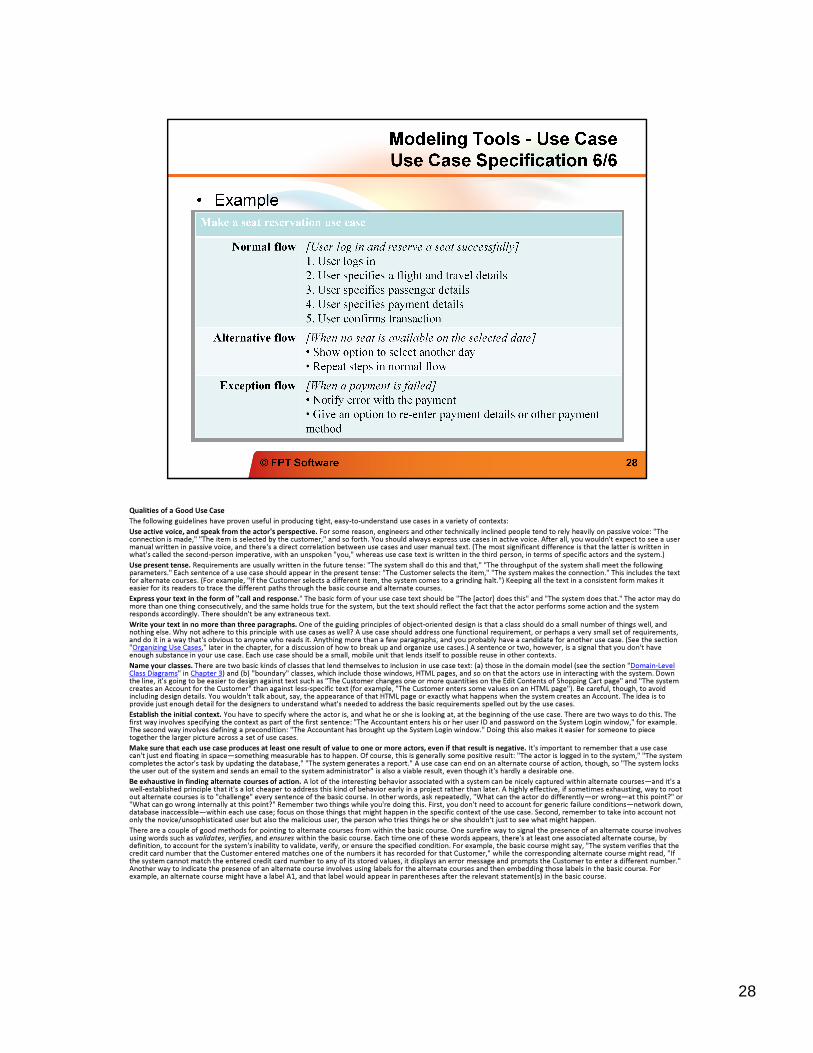
28
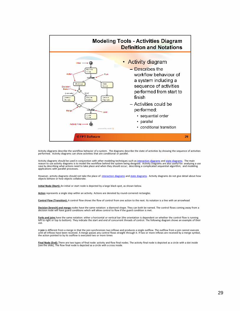
Activity diagrams describe the workflow behavior of a system. The diagrams describe the state of activities by showing the sequence of activities performed. Activity diagrams can show activities that are conditional or parallel.
Activity diagrams should be used in conjunction with other modeling techniques such as interaction diagrams and state diagrams. The main reason to use activity diagrams is to model the workflow behind the system being designed. Activity Diagrams are also useful for: analyzing a use case by describing what actions need to take place and when they should occur; describing a complicated sequential algorithm; and modeling applications with parallel processes.
However, activity diagrams should not take the place of interaction diagrams and state diagrams. Activity diagrams do not give detail about how objects behave or how objects collaborate.
Initial Node (Start): An initial or start node is depicted by a large black spot, as shown below.
Action represents a single step within an activity. Actions are denoted by round-cornered rectangles.
Control Flow (Transition): A control flow shows the flow of control from one action to the next. Its notation is a line with an arrowhead
Decision (branch) and merge nodes have the same notation: a diamond shape. They can both be named. The control flows coming away from a decision node will have guard conditions which will allow control to flow if the guard condition is met.
Forks and joins have the same notation: either a horizontal or vertical bar (the orientation is dependent on whether the control flow is runningleft to right or top to bottom). They indicate the start and end of concurrent threads of control. The following diagram shows an example of their use.
A join is different from a merge in that the join synchronizes two inflows and produces a single outflow. The outflow from a join cannot execute until all inflows have been received. A merge passes any control flows straight through it. If two or more inflows are received by a merge symbol, the action pointed to by its outflow is executed two or more times
Final Node (End): There are two types of final node: activity and flow final nodes. The activity final node is depicted as a circle with a dot inside (see the slide), The flow final node is depicted as a circle with a cross inside.
29
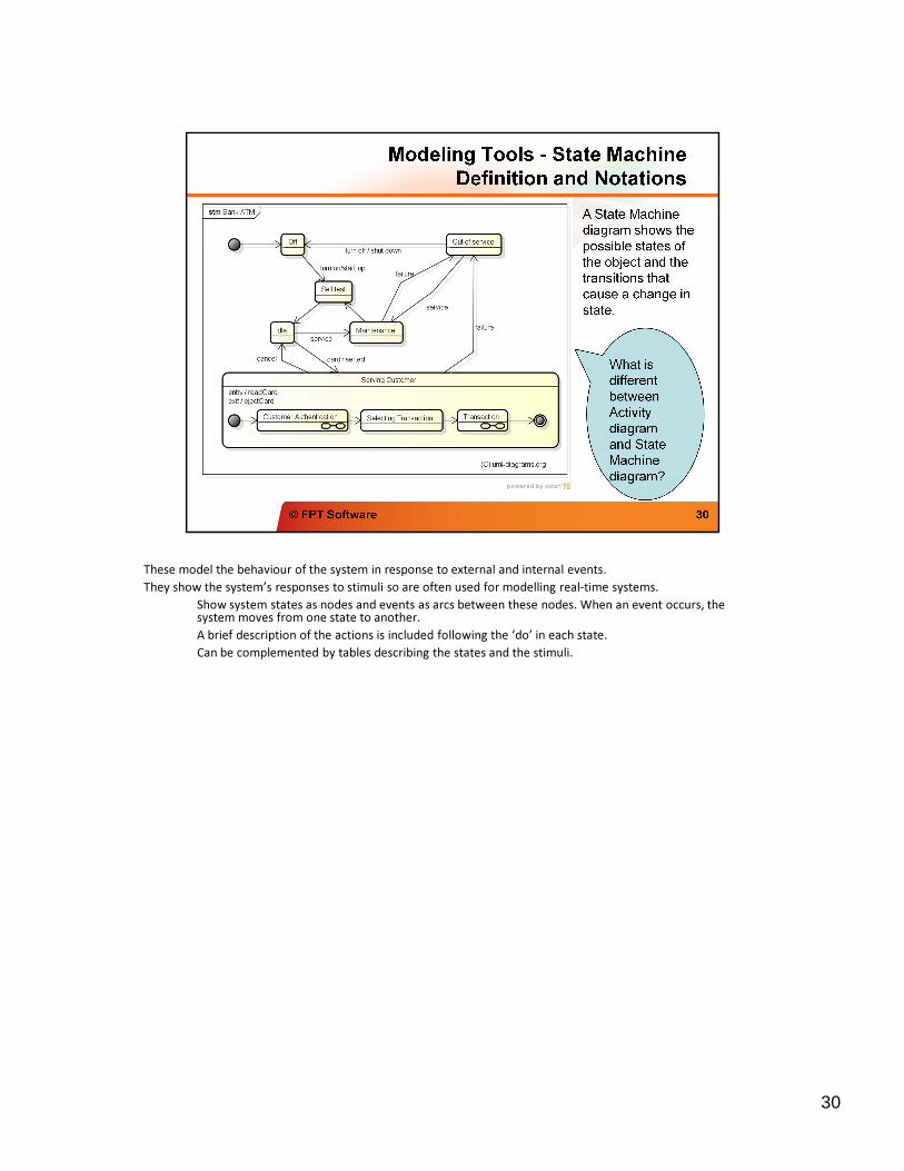
These model the behaviour of the system in response to external and internal events.
They show the system’s responses to stimuli so are often used for modelling real-time systems.They show the system’s responses to stimuli so are often used for modelling real-time systems.
Show system states as nodes and events as arcs between these nodes. When an event occurs, the system moves from one state to another.
A brief description of the actions is included following the ‘do’ in each state.
Can be complemented by tables describing the states and the stimuli.
30
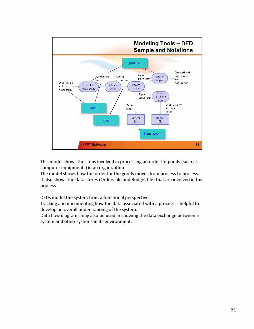
This model shows the steps involved in processing an order for goods (such as
computer equipments) in an organization.
This model shows the steps involved in processing an order for goods (such as
computer equipments) in an organization.
The model shows how the order for the goods moves from process to process.
It also shows the data stores (Orders file and Budget file) that are involved in this
process
DFDs model the system from a functional perspective.
Tracking and documenting how the data associated with a process is helpful to
develop an overall understanding of the system.
Data flow diagrams may also be used in showing the data exchange between a
system and other systems in its environment.
31
32
33