db4/db8 - tc electronic home...
TRANSCRIPT

Operation manualEnglish
DB4/DB8


3
Table Of COnTenTs
Table Of Contents .................................................. 3Important safety instructions.................................. 4Introduction ............................................................ 5Getting Started ...................................................... 6Mainframe - Front .................................................. 7Main frame - Rear.................................................. 8DSP and I/O Expansion cards ............................... 9DSP & Card Connection ...................................... 10Remote CPU ....................................................... 13TC ICON ............................................................. 14DB4/DB8 network & Updating Software .............. 15DB8/DB4 Network ............................................... 19Savvy WI-fI networking for DB8/DB4................... 20Basic Operation ................................................... 21Library - Recall .................................................... 23Library - Store ...................................................... 24Library - Bank ...................................................... 25Library - Delete .................................................... 26Routing - Page..................................................... 27Frame - System - Main ........................................ 28Frame - System -Main -GPI ................................. 29Frame - System -Main -GPI ................................. 30Frame - System -Main -GPI ................................. 31Frame - System - Main - MIDI ............................. 32Frame - System - I/O .......................................... 35Engine Edit ......................................................... 37Icon Setup ........................................................... 38SMPTE ................................................................ 39License agreement .............................................. 42Technical Specifications - Frame ......................... 43Technical Specifications - TC Icon & Remote CPU .................................... 44
Prod No: Prod No: 606148013 - Rev. 2TC Electronic, Sindalsvej 34, DK-8240 Risskov

4
ImpOrTanT safeTy InsTruCTIOns
1 Read these instructions.2 Keep these instructions.3 Heed all warnings.4 Follow all instructions.5 Do not use this apparatus near water.6 Clean only with dry cloth.7 Do not block any ventilation openings. Install in accordance with the
manufacturer’s instructions.8 Do not install near any heat sources such as radiators, heat registers,
stoves, or other apparatus (including amplifiers) that produce heat.9 Do not defeat the safety purpose of the polarized or grounding-type
plug. A polarized plug has two blades with one wider than the other. A grounding type plug has two blades and a third grounding prong. The wide blade or the third prong are provided for your safety. If the provided plug does not fit into your outlet, consult an electrician for replacement of the obsolete outlet.
10 Protect the power cord from being walked on or pinched particularly at plugs, convenience receptacles, and the point where they exit from the apparatus.
11 Only use attachments/accessories specified by the manufacturer.
12 Use only with the cart, stand, tripod, bracket, or table specified by the manufacturer, or sold with the apparatus. When a cart is used, use caution when moving the cart/apparatus combination to avoid injury from tip-over.
13 Unplug this apparatus during lightning storms or when unused for long periods of time.
14 Refer all servicing to qualified service personnel. Servicing is required when the apparatus has been damaged in any way, such as power-supply cord or plug is damaged, liquid has been spilled or objects have fallen into the apparatus, the apparatus has been exposed to rain or moisture, does not operate normally, or has been dropped.
Warning• Toreducetheriskoffireorelectricalshock,donotexposethis
equipment to dripping or splashing and ensure that no objects filled with liquids, such as vases, are placed on the equipment.
• Thisapparatusmustbeearthed.• Useathreewiregroundingtypelinecordliketheonesuppliedwiththe
product.• Beadvisedthatdifferentoperatingvoltagesrequiretheuseofdifferent
types of line cord and attachment plugs.• Checkthevoltageinyourareaandusethecorrecttype.Seetable
below:
• Thisequipmentshouldbeinstallednearthesocketoutletanddisconnection of the device should be easily accessible.
• Donotinstallinaconfinedspace.• Donotopentheunit-riskofelectricshockinside.
Caution:• Youarecautionedthatanychangeormodificationsnotexpressly
approved in this manual could void your authority to operate this equipment.
• TocompletelydisconnectfromACmains,disconnectthepowersupplycord from the AC receptacle.
• Themainsplugofthepowersupplyshallremainreadilyoperable.• Dangerofexplosionifbatteryisincorrectlyreplaced. Replace only with the same or equivalent type.• Ventilationshouldnotbeimpededbycoveringtheventilationopenings
with items, such as newspapers, tablecloths, curtains, etc.
Service• Therearenouser-serviceablepartsinside.• Allservicemustbeperformedbyqualifiedpersonnel.
EMC / EMIThis equipment has been tested and found to comply with the limits for a ClassBDigitaldevice,pursuanttopart15oftheFCCrules.These limits are designed to provide reasonable protection against harmful interference in a residential installations. This equipment generates, uses and can radiate radio frequency energy and, if not installed and used in accordance with the instructions, may cause harmful interference to radio communications. However, there is no guarantee that interference will not occur in a particular installation. If this equipment does cause harmful interference to radio or television reception, which can be determined by turning the equipment off and on, the user is encouraged to try to correct the interference by one or more of the following measures:
• Reorientorrelocatethereceivingantenna.• Increasetheseparationbetweentheequipmentandreceiver.• Connecttheequipmentintoanoutletonacircuitdifferent from that to which the receiver is connected.• Consultthedealeroranexperiencedradio/TVtechnician for help.
The user may find the following booklet, prepared by the Federal Communications Commission, helpful:“HowtoidentifyandResolveRadio/TVinterferenceProblems.”This booklet is available from the US. Government Printing Office, Washington, DC 20402, Stock No. 004-000-0034-4.
For the customers in Canada:ThisClassBDigitalapparatusmeetsallrequirementsoftheCanadianInterference-Causing Equipment Regulations. Cet appareil numérique de laclasseBrespectetouteslesexigencesduRéglementsurlematérielbrouilleur du Canada.
Voltage Line plug according to standard.
110-125V UL817andCSAC22.2no42. 220-230V CEE7pageVII,SRsection 107-2-D1/IEC 83 page C4.
240V BS1363of1984. Specification for 13A fused plugs and switched and unswitched socket outlets.
The lightning flash with an arrowhead symbol within an equilateral triangle, is intended to alert the user to the presenceofuninsulated“dangerousvoltage”withintheproduct’s enclosure that may be of sufficient magnitude to constitute a risk of electric shock to persons.
The exclamation point within an equilateral triangle is intended to alert the user to the presence of important operating and maintenance (servicing) instructions in the literature accompanying the product.
LicensesIf you have purchased any of the optional software LicensesortheTCIconSoftwareEditor,thenreadtheLicenseAgreementsintheAppendixsectionprior to use.

5
paGe HeaD
int
ro
du
ct
ion
5
InTrODuCTIOn
Thank youforchoosingDB8orDB4asyournextstepinaudio. Even if the near future is analog we are convinced youhavechosenwisely.ConsistencyinLoudnessisthesingle most important audio issue to get right in broadcast today.DB8andDB4employcuttingedgetechnologytoenable stations get rid of listener complaints about jumping levels, and to transmit in analog and digital with optimum processing for both feeds.
The Difference Between DB8 and DB4–DB8hasfourindependentprocessorsinoneframeandthus runs 4 independant Engine algorithms simultaneouly.
–DB4hastwoenginesbutcanruntwoprocessingenginesPLUSaLM6Radarmeter.
DB8isdesignedforlargebroadcastcenters,whileDB4may be a more appropriate match for a regional station, but they share the same processing, the same presets and the same physical I/O structure - and even the same programtocontrolthem.Manymachinesofbothtypescanbe controlled from one Icon program (included with this package), and they will identify themselves over a network, be it local or remotely located machines.
Software and Manual for DB8 and DB4Software updates for both machines are always released simultaneously, and the two machines share the same manual. The relevant differences are highlighted. Instead of bothnamesbeingprintedthroughoutthemanual,“DB8”isused as a generic term.
PresetsDB8andDB4includeanumberofinternationalstandardpresetsreadyforuse.Morepresetsarecontinuouslymadeavailable in software updates, and from the TC web-site. Presets are based on information from broadcasters around the world. Some are subtle, some aggressive, but they all provide outstanding audio resolution, never before available in a broadcast processor.
Identify Your OpportunitiesIf your station is an early mover in digital and seeking to identifyadvantages,DB8andDB4willprovideyouwithallthe possibilities you need to experiment and find the right competitive angle. The processors can also adapt to your audience’s changing needs, or audio strategy could even be changed from program to program.
Technical IntegritySynchronous 48 kHz sampling and 48 bit processing throughout. Wide range, high order jitter rejection. The DB8/DB4platformiswithoutcompromises.Infact,hundreds of machines could be cascaded without even degrading the transmitted sound.
FoundationTC’s involvement with high quality digital audio dates back to the mid eighties with pre-DSD technology being employed in the still ubiquitous delay, 2290. TC’s commitment to digital excellence continued over the years with equipment for the music, film and mastering industries.ThemultichannelprocessinginDB8andDB4,forinstance, was originally developed for film. Those tools have been adjusted for broadcast use and are now part of your arsenal. Or dynamics control, where some of the latest end-listener distortion canceling methods originally inventedformasteringhavebeenbuiltin.DBprocessorseven include advanced loudness and true-peak meters, foundedonITUandEBUstandardsTChasbeenasignificant contributor to.Manyyearsofexperiencewithanaloganddigitalbroadcastcombined with the know-how of skilled engineers is the strongbaseoftheDB8/DB4platform.Fromthepuristandquality conscious hardware engineers to software writers ofwhomsomewereinvolvedwithdesigningtheMPEGcodecs, the team forms a competent, non-dogmatic design group ready to take broadcast audio to the next level.We are confident you will value your new possibilities.
6
GeTTInG sTarTeD
X-COUPLED ETHERNET CABLE
100-240V AC
DB-8
PC or Mac
25PIN DSUB TO XLR
8 x XLR FOR DIGITAL I/O
TV TRANSMISSION PROCESSOR /DB-8
RESET
SUPPLY 2SUPPLY 1
DUAL POWER REDUNDANCY
STATUS
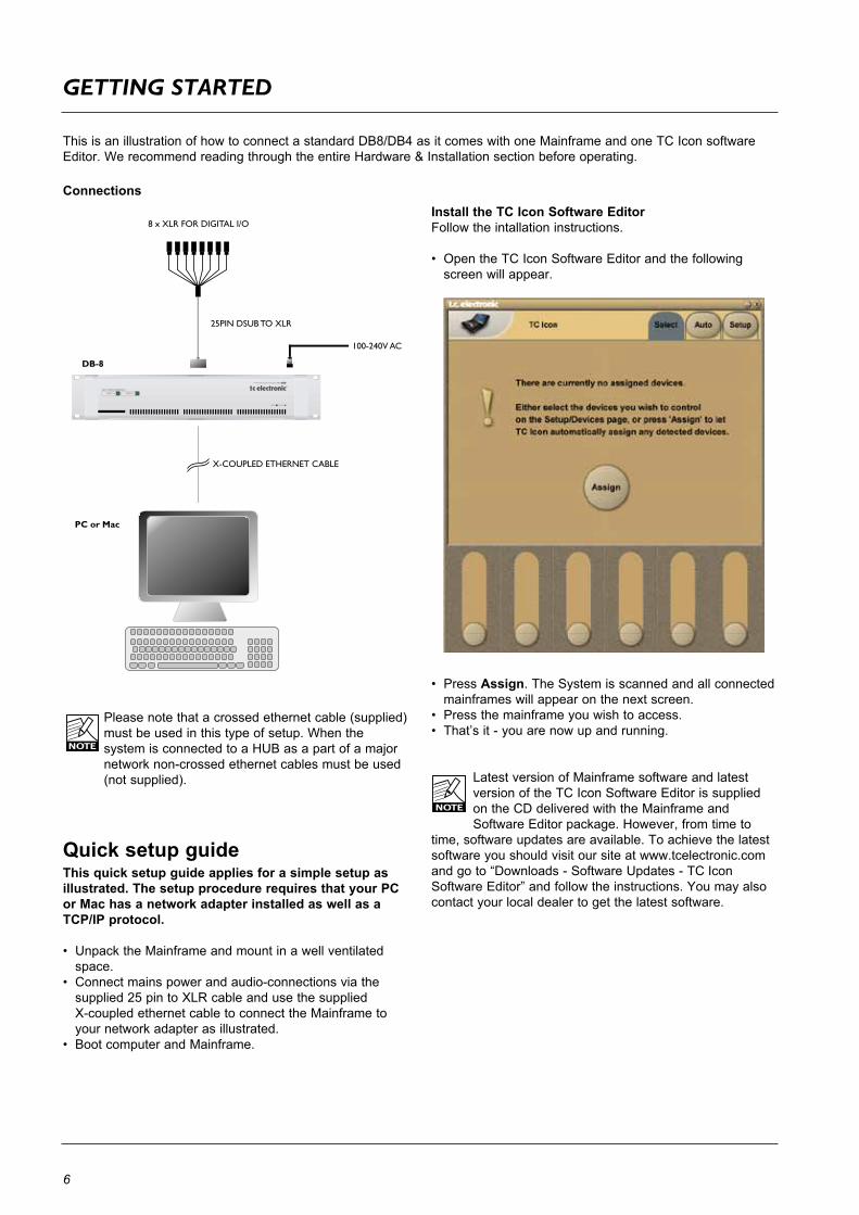
ThisisanillustrationofhowtoconnectastandardDB8/DB4asitcomeswithoneMainframeandoneTCIconsoftwareEditor. We recommend reading through the entire Hardware & Installation section before operating.
Please note that a crossed ethernet cable (supplied) must be used in this type of setup. When the systemisconnectedtoaHUBasapartofamajornetwork non-crossed ethernet cables must be used (not supplied).
ConnectionsInstall the TC Icon Software EditorFollow the intallation instructions.
• OpentheTCIconSoftwareEditorandthefollowingscreen will appear.
• PressAssign. The System is scanned and all connected mainframes will appear on the next screen.
• Pressthemainframeyouwishtoaccess.• That’sit-youarenowupandrunning.
LatestversionofMainframesoftwareandlatestversion of the TC Icon Software Editor is supplied ontheCDdeliveredwiththeMainframeandSoftware Editor package. However, from time to
time, software updates are available. To achieve the latest software you should visit our site at www.tcelectronic.com and go to “Downloads - Software Updates - TC Icon SoftwareEditor”andfollowtheinstructions.Youmayalsocontact your local dealer to get the latest software.
Quick setup guideThis quick setup guide applies for a simple setup as illustrated. The setup procedure requires that your PC or Mac has a network adapter installed as well as a TCP/IP protocol.
• UnpacktheMainframeandmountinawellventilatedspace.
• Connectmainspowerandaudio-connectionsviathesupplied25pintoXLRcableandusethesuppliedX-coupledethernetcabletoconnecttheMainframetoyour network adapter as illustrated.
• BootcomputerandMainframe.

7
paGe HeaD
HW
& i
ns
ta
ll
at
ion
7
maInframe - frOnT
TV TRANSMISSION PROCESSOR /DB-8
RESET
SUPPLY 2SUPPLY 1
DUAL POWER REDUNDANCY
STATUS
Mainframe Front
Power Supply 1 & Power Supply 2 LEDsDB8/DB4featurestwofullyindependantpowersupplies.EachpowersupplyhasitsownstatusLED.
-ForeachpowersupplyagreenLEDindicatesthatexternal power is connected and the power supply is fully functioning. -AredLEDindicatesaproblem.Eitherthereisnoexternal power connected or there is a problem at certain checkpoints in the relevant power supply.
Due to the redundant design the frame will still be fully operationable, however, we advise that you address the issue and investgate the cause of the error indication at the first given opportunity.
-NolightinanyLEDs-nopowerconnected.
Notice that only one power supply is necessary for DB8/4torun.StatusisalsoindicatedintheTCIconEditor.
Reset keyPress and hold during boot up to reset I/P address to default. Default I/P address in 192.168.1.xx - where xx is the last two digits of the frame’s serial number.Pressandholdapprox.5secondsuntilLEDblinksduringoperation, to reset only ethernet communication without interrupting audio.
Status LEDGreencolorindicates“OK”.FlashingorangeLEDindicatesswupdateinprogress.Red indicates a network problem. Check cables.
PCMCIA slotFor future software facilities and handling of additional preset banks.

8
maIn frame - rear
DUAL POWER INLETS
2 1
LANETHERNET
ONOFF
GROUNDLIFT
100-240V AC
50-60Hz 60W
~
SERIAL NO.
CAUTIONSHOCK HAZARD DO NOT OPEN
AVIS: RISIQUE DE CHOC
ELECTRIQUE NE PAS OUVRIR
TYPE:M6000F20
MADE IN DENMARK
USC
R
THIS CLASS B DIGITAL DEVICE MEETS ALL REQUIREMENTS OF THE CANADIAN INTERFERENCE-CAUSING EQUIPMENT REGULATIONS
AND COMPLIES WITH PART 15 OF THE FCC RULES. OPERATION SUBJECT TO CONDITIONS STATED IN THE MANUAL.
WARNING TO REDUCE THE RISK OF FIRE OR ELECTRIC SHOCK DO NOT EXPOSE THIS EQUIPMENT TO RAIN OR MOISTURE.
MIDI IN MIDI THRU MIDI OUT REMOTESMPTE PEDAL
IO-6000 SDI HDAUDIO EMBEDDER / DE-EMBEDDER
BA individually buffered
SDI inputs
IEEE-1394
bypass relay
SDI outputs
DSP6000 SDIAUDIO EMBEDDER / DE-EMBEDDER
BA individually buffered
SDI inputs
IEEE-1394
bypass relay
SDI outputs
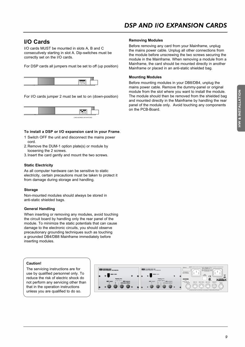
Mainframe RearI/O 6000 SDI HD - expansion cardDSP6000 SDI card
DSP & I/O expansion slots A B CDSP,AB,andCslotsshouldbefilledconsecutivelyALWAYSstartingwithaDSPcardintheDSPslot(upperleft).Dual-space cards are installed adjacently as illustrated above.
Following DSP cards are available:- DSP6000 SDI (dual space)- AES3 COAX DSP-DSPAES/EBUEightchannel(singlespace)
Following I/O cards are available:- I/O-6000 SDI HD- AES3 COAX I/O-AESOCTALI/O(Balanced)
Dual Power InThe Dual Power input for extended operational security andstabilityaccepts100-230VAC.50/60Hz.Connect to two independent power sources to be safe in case of a fuse blow.
SMPTE1/4”connectionforSMPTEsync.Input.
Ethernet/LANConnection for external control devices such as a computer with installed net adaptor or the TC Icon.The type is 32 bit PCI Ethernet interface fully compliant withIEE802.3u10/100MbpsCSMA/CDstandards.Theconnectortypeisa100Base-TRJ-45(CN13)
Ground LiftUse this standard chassis ground lift if you encounter problemswith“hum.”
MIDI In, Thru and Out5 pin DIN connectors.
RemoteThis connection is for service and test purposes only.
PedalGeneral Purpose Input (GPI). GPI input for switching of up to 8 presets.
Rackmounting Advice• TheDB8/DB4mainframeshouldnotbeplacedinan
environment with a temperature exceeding 50 degrees celsius.
• Donotcovertheventilationopeningsonthesidesoftheframe.
The cooling fans are activated according to the temperature inside.
DSP
B
C
D
WarningDo NOT mount an ADA 24/96 card in any of the card slots. DB4/DB8 MKII does NOT support the ADA 24/96 card and the card will be damaged if mounted in a DB4/DB8 MKII frame!
9
HW
& i
ns
ta
ll
at
ion
I/O CardsI/OcardsMUSTbemountedinslotsA,BandCconsecutively starting in slot A. Dip-switches must be correctly set on the I/O cards.
For DSP cards all jumpers must be set to off (up position)
For I/O cards jumper 2 must be set to on (down-position)
To install a DSP or I/O expansion card in your Frame.1 Switch OFF the unit and disconnect the mains power
cord.2.RemovetheDUM-1optionplate(s)ormoduleby loosening the 2 screws.3. Insert the card gently and mount the two screws.
Static ElectricityAs all computer hardware can be sensitive to static electricity, certain precautions must be taken to protect it from damage during storage and handling.
StorageNon-mounted modules should always be stored in anti-static shielded bags.
General HandlingWhen inserting or removing any modules, avoid touching the circuit board by handling only the rear panel of the module. To minimize the static potentials that can cause damage to the electronic circuits, you should observe precautionary grounding techniques such as touching agroundedDB4/DB8Mainframeimmediatelybeforeinserting modules.
Removing ModulesBeforeremovinganycardfromyourMainframe,unplugthe mains power cable. Unplug all other connections from the module before unscrewing the two screws securing the moduleintheMainframe.WhenremovingamodulefromaMainframe,thecardshouldbemounteddirectlyinanotherMainframeorplacedinananti-staticshieldedbag.
Mounting ModulesBeforemountingmodulesinyourDB8/DB4,unplugthemains power cable. Remove the dummy-panel or original module from the slot where you want to install the module. The module should then be removed from the shielded bag andmounteddirectlyintheMainframebyhandlingtherearpanel of the module only. Avoid touching any components onthePCB-Board.
Caution!The servicing instructions are for use by qualified personnel only. To reduce the risk of electric shock do not perform any servicing other than that in the operation instructions unless you are qualified to do so.
DUAL POWER INLETS
2 1
LANETHERNET
ONOFF
GROUNDLIFT
100-240V AC
50-60Hz 60W
~
SERIAL NO.
CAUTIONSHOCK HAZARD DO NOT OPEN
AVIS: RISIQUE DE CHOC
ELECTRIQUE NE PAS OUVRIR
TYPE:M6000F20
MADE IN DENMARK
USC
R
THIS CLASS B DIGITAL DEVICE MEETS ALL REQUIREMENTS OF THE CANADIAN INTERFERENCE-CAUSING EQUIPMENT REGULATIONS
AND COMPLIES WITH PART 15 OF THE FCC RULES. OPERATION SUBJECT TO CONDITIONS STATED IN THE MANUAL.
WARNING TO REDUCE THE RISK OF FIRE OR ELECTRIC SHOCK DO NOT EXPOSE THIS EQUIPMENT TO RAIN OR MOISTURE.
MIDI IN MIDI THRU MIDI OUT REMOTESMPTE PEDAL
IO-6000 SDI HDAUDIO EMBEDDER / DE-EMBEDDER
BA individually buffered
SDI inputs
IEEE-1394
bypass relay
SDI outputs
DSP6000 SDIAUDIO EMBEDDER / DE-EMBEDDER
BA individually buffered
SDI inputs
IEEE-1394
bypass relay
SDI outputs
Dsp anD I/O expansIOn CarDs

10
Dsp & CarD COnneCTIOn
SDI cardsTheSDIcardforDB4/DB8supportsallcommonlyusedSDandHDformats.Whilede-embeddingandembedding8channels of audio (48 kHz, 24 bit), selectable from the four SDI Groups in chunks of four audio channels, it passes the video side untouched.
Processing may be inserted on any two of the four SDI Groups, and re-embedding may take place on any two groups. Consequently, the machine enables cross patching of audio and format conversion between SDI Groups. The design features two separate SDI inputs, of which one is active at a time, and two parallel, separately buffered outputs.
TheDB’spresentanattractiveSDIsolutionwithmassivejitterrejection,48bitprocessingandlowlatency.Theyalsofeature bit transparent, synchronous data handling, enabling routing of data reduced audio, such as AAC, DTS or Dolby E.
DSP6000 SDI I/O6000 SDI HD
HD Audio• Embeddedaudiomultiplexeranddemultiplexer• Supports38HDvideoformats• Supportseightaudiochannelsatonetime• FullySMPTE299Mcompliant&compatiblewithcommon
non-compliances• Uptoeightbiterrorscanbecorrectedineachaudiodata
packet• Fullsupportfor48kHzsynchronousorasynchronous
16-bit, 20-bit and 24-bit audio• Allfouraudiogroupscanbedeleted•Anytwoaudiogroupscanbereplacedwhenoperatingin
multiplexer mode
SD Audio • Embeddedaudiomultiplexeranddemultiplexer• Supports6SDvideoformats• Supportseightaudiochannelsatonetime• ComplianttoSMPTE272MAandC&compatiblewith
common non-compliances• Fullsupportfor48kHzsynchronous16-bit,20-bitand
24-bit audio• Programmableaudiosampledistribution• Allfouraudiogroupscanbedeleted• Anytwoaudiogroupscanbereplacedwhenoperatingin
multiplexer mode
Automatic BypassThe DSP6000 SDI card (bypass version) features automatic bypass at power-down or at loss of power. Even at boot-up audio and video is passed lossless to transmission.
SDI I/O Expansion card• WiththeSDIexpansioncardinstalledupto16I/Ochannelscanbehandledeitherin1TVstreamwith16channelsorin2TVstreamswith8channelseach.
Technical notesMaxrecommendedcablelengthis60meterstoandfromDB8/DB4.CabletypeshouldcomplytoSMPTEstandards,suchasBelden1694orbetter.Note that in bypassed mode the total cable length pre AND post the unit should not exceed 60 meters.
When an installation is finished, please check bypass functionalitybyturningofftheDBprocessorinsitutotakecable types and cables lengths into account.

11
HW
& i
ns
ta
ll
at
ion
11
Dsp & CarD COnneCTIOn
IntroductionTheoptionalAES-3Coaxcardwith8BNCconnectionsis especially designed for broadcast installations as they oftenpreferthe75OhmunbalancedBNCconnectionsthatsupport considerably longer cables.
GroundingA jumper on the card determines grounding to chassis status. Per default the card is grounded to chassis.
If you need to change the grounding status, follow this procedure:
• Disconnectmainspowercord.• LoosenthetwoscrewsholdingtheDSPcardand remove the card gently.• Movethejumpertopins: 2-3 : Floating (not grounded) 1-2 : Grounded (default)• InsertthecardgentlyintheDSPslotandremount the screws.
Hardwire Bypass at power offAt power off the frame is hardwire-bypassed via relays ensuring NO signal loss.
SYNC IN, WORD CLOCKRefer to infomation on next page.
General HandlingWhen inserting or removing any modules, avoid touching the circuit board by handling only the rear panel of the module. To minimize the static potentials that can cause damage to the electronic circuits, you should observe precautionary grounding techniques such as touching a groundedMainframeimmediatelybeforeinsertingmodules.
AES OCTAL - Expansion
Eight channel I/O expansion card on with BNC connectors.
Caution!The servicing instructions are for use by qualified personnel only. To reduce the risk of electric shock do not perform any servicing other than that in the operation instructions unless you are qualified to do so.
AES3 COAX - DSP

12
Dsp & CarD COnneCTIOn
Use the supplied cable to connect the AES/EBU Inputs/Outputs.
Cable type is twisted pair (12 pairs) with common screen. Recommended impedance: 110 Ohm.
OneendisequippedwithanAES/EBU25pinD-Subconnector,theotherendisequippedwithfourmaleXLR’sandfourfemaleXLR’s.MaleXLR’saremarkedwith:Out-1to4.FemaleXLR’saremarkedwith:IN-1to4.
Extension cables must be constructed according to AES/EBU-3standards.
Following is the pin-out:
Cable pair Pinnumber number XLR XLR-pin Assignment
1 1a Female 1 2 Input 1/2 +2 2a Female 2 2 Input 3/4 +3 3a Female 3 2 Input 5/6 +4 4a Female 4 2 Input 7/8 +5 5a Male1 2 Output1/2+6 6a Male2 2 Output3/4+7 7a Male3 2 Output5/6+8 8a Male4 2 Output7/8+9 No connection No connection10 9a Female 1 1 Common11 No connection No connection12 9b Female 2 1 Common13 10a Female 3 1 Common13 10b Female 4 1 Common14 1b Female 1 3 Input 1/2 -15 2b Female 2 3 Input 3/4 -16 3b Female 3 3 Input 5/6 -17 4b Female 4 3 Input 7/8 -18 5b Male1 3 Output1/2-19 6b Male2 3 Output3/4-20 7b Male3 3 Output5/6-21 8b Male4 3 Output7/8-22 11a Male1 1 Common23 11b Male2 1 Common24 12a Male3 1 Common24 12b Male4 1 Common25 Shield no connection Common
Twisted cable pairs must be respected
Sync In Word ClockForconnectionstoexternalclockviathestandardBNCconnector (see illustration above). When several devices are connected in a chain and synced via Word Clock, termination on the last device of the chain is necessary. AstheDB8/DB4isexpectedtobethelastunitinsuchachain (or the only), the factory default setting on the DSP cardis:TERMINATED(75Om).
If you need to terminate the Word Clock signal elsewhere in the chain you will need to un-terminate the DSP card. To do this you must remove the DSP card from the mainframe and remove the termination jumper:
• Switchoffthepoweranddisconnectmainpowercord.• LoosenthetwoscrewsholdingtheDSPcardand remove the card gently.• RemovetheterminatingjumperneartheBNCplug.• InsertthecardgentlyintheDSPslotandremount the screws.
Pins connected via jumper : Terminated (75 Om).Pins NOT connected via jumper : Not Terminated
Termination jumper
BNC connector

13
HW
& i
ns
ta
ll
at
ion
remOTe Cpu
Remote CPU front panel
Remote CPU rear panel
LAN 1 connection for setups with multiple frames
COM port 1 COM port 2
PS-2 connection for PC keyboard and mouse
Connection for TC Icon
2 x USBType A StandardConnectors
Power In100 - 240V
Connection for VGA monitor
Power KeySwitchespowerOn/Off.GreenLEDindicatespoweronstate.
Ethernet Connection32 bit PCI Ethernet interface fully compliant with IEE 802.3u10/100MbpsCSMA/CDstandards.Theconnectortypeisa100Base-TRJ-45(CN13)
Connection for PC keyboard or mouseAstandardPS2Y-splittermustalwaysbeusedwhenconnecting a PS2-mouse, a keyboard or both. This cable is not supplied with the unit.
Connection for TC Icon36 pin multi-cable connection for TC Icon.
TC Connection Cable.Use the special TC Icon cable supplied with the unitONLY!
USB ConnectionUSBconnectionforsomeTCproductswithUSBconnection.E.g.LM2
MonitorByconnectingamonitorviathisstandard15pinD-Subyou can have the exact same picture as displayed on the TC Icon, running in parallel with the Icon. Color depth is 24 bit with a screen resolution of 640 x 480 pixels at 60Hz.
PowerConnect100-240VAC,50/60Hzauto-select.
Rack-mounting Advice• TheCPUunitshouldnotbeplacedinanenvironment with a temperature exceeding 50 degrees celsius. • Donotcovertheventilationopeningsonthebackofthe Remote CPU.
The cooling fan is activated according to the temperature inside.
Com ports / RS232For connection of TC units with RS232 interface. E.g. P2 andDB2.
Ethernet/LAN connection for sw updates etc.
The following section describes the TC ICON hardware remote control.Upto8mainframescanbecontrolledviatheTCICONhardwareremotebutDB8/DB4unitsaremostoftencontrolledviaPCorMacusingthefreeTCIconSoftwareEditor.WhenusinguptofourinstancesoftheTCIconSoftwareEditor;32frames can be controlled simultaneously. Please find descriptions of both in the following manual sections.

14
TC ICOn
ScreenThe TC Icon screen is a touch-sensitive capacitive screen. Touch calibration as well as brightness and colors can be adjusted/selected in the TC Icon Setup menu.
MaintenanceThe touch screen must be cleaned only with a soft cloth slightly moistened with water or a mild detergent solution.
Do not spray liquids directly on the screen.
FadersThe Faders are touch-sensitive. The sensitivity of the Faders can be adjusted so response to movement is achieved only when operated with your finger-tips. This way unintended movement of the Faders with e.g. a sleeve etc. will not result in changes in parameter values.The sensitivity can be adjusted in the TC Icon Setup menu.
TC Connection Cable.UsethespecialTCIconcablesuppliedwiththeunitONLY!No other cables can be used. The 7.5 meters (22 feet) cable cannot be extended as this will reduce the power for theIconsuppliedviathecable!
Mic stand mountingTherearetwostandardthreads.3/8”and5/8”.TheTCIconcan be mounted on both types without further accessories.
Mounting of plate.MountthesuppliedplateontherearoftheTCIcon,toassure stable operation when placed on a table or similar. This is easily done using the 4 screws and screwdriver supplied with the unit.
DimensionsD: 279mm W: 198mm H front: 33mm
TC Icon Front TC Icon Rear
198 mm
15
HW
& i
ns
ta
ll
at
ion
upDaTInG Db4/Db8 mKII sOfTware
Keeping your software updatedDB4/DB8isaconstantlyevolvingplatformandupdatingsoftwareisastandardproceduretokeepthesystemup-to-date.Depeding on your setup, software-updates can be done in a couple of different ways described on the following pages.
Software typesTherearethreetypesofsoftwareinaDB4/DB8mainframe,onefortheTCIconRemoteCPUMKIIandthentheTCIconSoftwareEditorforPCandMac,thatcanbeusedinsteadofaTCIcon(hardwareversion)
• Framesoftware• Net(Ethernet)software• DSPsoftware
• SoftwarefortheTCIconRemoteCPUMKII• TCIconSoftwareEditorformMacorPC
Beforedivingintotheactualupdateprocedures,youshouldcheckwhetheryouhavethelatestsoftwareinstalledalready.

16
upDaTInG Db4/Db8 mKII sOfTware
RemoteCPUMKIIsoftwareisupdateddirectlyviatheinternet.
- ConnectRemoteCPUMKIILAN2toyourinternetrouterusing a standard ethernet cable
- Go to the Setup/Update page and press the UPDATE FROMTCWEBSITEbutton
- That’sit!
Updating Remote CPU MKII software
INTERNET
Update Remote CPU 2
REMOTE CPU MKII LAN 2
TC ICON MKII
StandardEthernet cable
Ifyouseeamessage“Downloadfromwebfailed”,gototheSetup/Net page and ensure that it says: “Connected.TCWebsiteAvailable”,underInternetDHCPConnection(LAN2)
Ifthemessageis:“Connected.TCWebsiteNotAvailable”or“LAN2NotConnected”,thencheckcablesandtryagain.If the problem continues you may need to look into firewall issues with your network administrator.

17
HW
& i
ns
ta
ll
at
ion
upDaTInG Db4/Db8 mKII sOfTware
DB4/DB8 MKII
TC ICON EDITORon PC OR MAC
Update Mainframe SW
X-CoupledEthernet cable
TV TRANSMISSION PROCESSOR /DB-8
RESET
SUPPLY 2SUPPLY 1
DUAL POWER REDUNDANCY
STATUS
Updating Mainframe 6000 MKII software
- DownloadandinstallTCIconEditoronaMacoraPC- Download Frame, DSP & Net software to a folder on your
computer.
PC example:Create a folder in the root directory (C), and call the folderDB8kupdate.Thepathforthisfolderisthen“C:\DB8update”. Unzip and place the Frame, DSP & Net software in this folder.
Macexample:CreateafolderonyourMacintoshHDandcallthefolders6kupdate. The path is then “//Volumes/Macintosh HD/DB8update”.Unzip and place the Frame, DSP & Net software in this folder.
- Disconnect your computer from your internet router- ConnecttheDB8MKIILANporttoyoucomputers
netcard using a X-coupled ethernet cable- Open the TC Icon Editor, select the Frame to update and
go to the Frame/System/Update page- Enter the path for the software: “C:\DB8update” (for Windows)
or “//Volumes/Macintosh HD/S6kupdate”(forMac)as
Update Folder path
- Select Frame and press Update SW- Select Net and press Update SW- Select DSP and press Update SW
The Icon Editor shows the update status via a progress bar.
A log file of the update can be obtained for service purposes. The file is saved at the location where the software is updated from. The file lists the result of the operation and can be opened with most text editors.
To verify correct update-procedure has taken place, check the software version numbers both before and after an update. These version numbers are locatedontheFrame/System/Versionpage.
18
upDaTInG Db4/Db8 mKII sOfTware
TC ICON EDITORon PC OR MAC
8 x XLR FOR DIGITAl I/O
8 x XLR FOR DIGITAl I/O
SWITCH/ROUTER
REMOTE CPU MKII
100 MBit HUB
LAN 2
DB8/DB4 MKII
DB8/DB4 MKII
Standard Ethernet Cable
Standard Ethernet Cables
TC ICON ELEVATEDMounted on 3/4” or 5/8” fittings
TC ICON MKII
CENTRAL SERVER
“TC NETWORK” (Static IP) - STUDIO A
DB8/DB4 MKII
LAN 1
LAN 2
TC ICON MKII
LAN 1
“TC NETWORK” (Static IP) - STUDIO B
INTERNET
X-Coupled ethernet cable
Static IP 10.10.10.1
Static IP 10.10.10.2
Static IP 10.10.10.4
DHCPe.g. 192.168.1.1
DHCPe.g.192.168.1.10
Static IP 10.10.10.1
Static IP 10.10.10.2
Static IP 10.10.10.3
DHCPe.g. 192.168.1.2
CENTRAL SERVER
TV TRANSMISSION PROCESSOR /DB-8
RESET
SUPPLY 2SUPPLY 1
DUAL POWER REDUNDANCY
STATUS
TV TRANSMISSION PROCESSOR /DB-8
RESET
SUPPLY 2SUPPLY 1
DUAL POWER REDUNDANCY
STATUS
TV TRANSMISSION PROCESSOR /DB-8
RESET
SUPPLY 2SUPPLY 1
DUAL POWER REDUNDANCY
STATUS
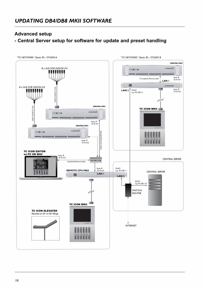
Advanced setup - Central Server setup for software for update and preset handling

19
HW
& i
ns
ta
ll
at
ion
upDaTInG Db4/Db8 mKII sOfTware
Updating your software:• Downloadthesoftwarefrom: http://www.tcelectronic.com/system6000support.asp
and place the software in a shared folder on the “central server”.
• Selecttheframeyouareabouttoupdate• GototheFrame-System-Update-Framepage• ThensettheUpdateFolderpathtothesharedfolder• PressUpdateSW• RepeatforDSPandNET(Ethernet)
Example: PC update folder path
Example: MAC update folder path
Log File,As explained on the previous page, a log file of the update can be obtained for service purposes. The file is saved at the location where the software is uploaded from. The file lists the result of the operation and can be opened with most text editors.The file is saved in the same folder as the software is placed and read/write access for that folder must be set.
Central Server (MotherShip) setupThis is a typical setup in larger studio facilities with several rooms, where you place software updates and e.g. a preset vault on a central server/computer in a shared folder.
The illustration on the previous pages shows two studios and a central server with internet access.
LAN 1 TC Network connects:- LocalDB4/DB8Mainframes- LocalRemoteCPULAN1- E.g.PC/MacrunningtheTCIconEditor
LAN 2 Internet- Connects to central server and internet
To learn about shared folders please refer to the sections:- Shared folders PC - basics - Shared folders Mac - basics
Two networks - two sets og IP addressesThissetupincludestwonetworks.Thestatic“TCNetwork”and the DHCP. Each network must use its own unique group of IP addresses.
We assume that the Router in the uses the standard group of IP addresses: 192.168.1.xx, and we must therefore giveTCIconRemoteCPUMKII’sLAN1andallDB4/DB8mainframes its own group.E.g. 10.10.10.xx, where x is unique for each unit. (please see illustration on the previous page)
- FirstchangetheIPaddresoftheDB4/DB8Mainframesto 10.10.10.x via the TC Icon Editor.
Reboot each frame- ThenchangetheLAN1IPaddressontheRemoteCPU MKIItoe.g.10.10.10.x ReboottheRemoteCPUMKII
20
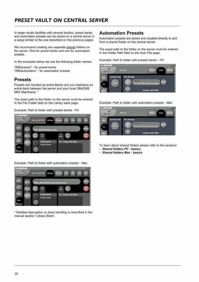
preseT VaulT On CenTral serVer
In larger studio facilities with several studios, preset banks and automation presets can be stored on a central server in a setup similar to the one described on the previous pages.
We recommend creating two seperate shared folders on the server. One for preset banks and one for automation presets.
In the examples below we use the following folder names:
“S6Kpresets”-forpresetbanks“S6Kautomation”-forautomationpresets
PresetsPresetsarehandledasentireBanksandyouload/saveanentirebankbetweentheserverandyourlocalDB4/DB8MKIIMainframe.*
The exact path to the folder on the server must be entered intheFileFolderfieldontheLibrarybankpage.
Example: Path to folder with presets banks - PC
Example: Path to folder with automation presets - Mac
*Detaileddescriptiononbankhandlingisdescribedinthemanualsection“LibraryBank”.
Automation PresetsAutomation presets are stored and recalled directly to and from a shared folder on the central server.
The exact path to the folder on the server must be entered in the Folder Path field on the Auto File page.
Example: Path to folder with presets banks - PC
Example: Path to folder with automation presets - Mac
To learn about shared folders please refer to the sections:- Shared folders PC - basics - Shared folders Mac - basics

21
HW
& i
ns
ta
ll
at
ion
neTwOrK basICs
Subnet Mask & TCP/IP addressesTheSubnetMaskisanumberthatdefinesagroupofcomputers(orIcons/Mainframes)connectedtothenetwork.AllunitsinthegroupmusthavethesameSubnetMask.TheDB8SubnetMaskisbydefault255.255.255.0
The TCP/IP address is unique to each unit connected in the network. An IP address consists of 4 numbers separated by a“.”Example:192.168.1.1Thefirstthreenumbers(e.g.“192.168.1”)mustbethesame for each unit, but no two units in the subnet can have the same the last number.
The TC Icon default address is : 192.168.1.125The M6000 default address is : 192.168.1.xx
-where“xx”isidenticaltothelasttwodigitsintheMainframesserialnumber.ThiswaymultipleDB8Mainframescanbesetupdirectlyoutoftheboxwithoutchanging the IP numbers.If your computer’s IP address (or any in the network) is one of the above you have two options. Either to alter the three last number in your computer’s IP address or to alter the lastnumberintheTCIconandMainframeIPaddresses.
Setting Subnet Mask & TCP/IPSettingtheSubnetandTCP/IPonDB8Mainframeisdonevia the TC Icon page: frame/system/main/net
SettingTCP/IPonTCIconRemoteCPUMKIIisdoneonvia the Setup/Net page.
Resetting a frames IP addressBypressingandholdingtheresetbuttononthefrontpanelduring boot-up, the frames IP address can at all times be resettodefault:192.168.1.xx*,-where“xx”isthelasttwodigits in the frames serial number.
*Iftheframesserialnumberendson“00”,theIPaddresswill be: 192.168.1.100,as“00”isnotavalidIPnumberinall networks.
There is a small risk that two frames have the same last 2 digits in the serial number and thus will conflict after a reset. Solution: - reset one frame and change its IP address before connecting the second.
Setting Subnet Mask & TCP/IP on a PCTofindtheTCP/IPaddressandtheSubnetMasksettingson your computer running Windows:
Example - Windows XPGo to Control Panel, Network Connections, Internet Protocol (TCP/IP)
Subnet Mask & TCP/IP address on a Mac
Example OSX• Goto“SystemPreferences-Network• UnderConfigureselect“manually”• SetTCP/IPaddress
For further information please refer to you operating systems manual.

22
neTwOrK basICs
Shared folders PC - basicsWhensharingafolderonWindowsXP/VISTA/WIN7youhave to make sure that the user of the TC Icon Remote CPUMKIIhasrightstoaccessread/writeinthesharefolder.
The default user on your hardware ICON is already setup:
User name : ICONPassword : Administrator(Notice the capital letters, as these are case sensitive)
This user has to be added on the computer holding your shared folder for software updates and preset handling:
- Press start in the lower left corner of your desktop- Rightclick“MyComputer”andclick“Manage”
ComputerManagementnowappearsandyouclick“LocalUsersandGroups”
Then“Users“and“Groups”appearandyoudoubleclickon“Users”
Youtypicallyhave3accountsonyoursystem,Administrator, Guest, and the default account you created whileinstallingwindows.Younowhavetoaddanewaccount!
Yourightclicktheblankspaceunderneaththe3accountsandclick“NewUser”
Type in user name : ICONAnd Password : Administrator
LeaveFullnameandDescriptionblankunlessyouneedthese information. All check boxes should be left as is.
Click“Create”andthe“Close”andtheusernowhasrightsto access the computer.
Now go to the folder you want to share• Right-clickonthefolderandselectproperties• SelectSharing• Mark“Sharethisfolder”• Typeinthename”iconupdate”assharename• Mark“Maximumallowed”inUserLimit
• Thenpress“Permissions”andallow:FullControl,Changeand Read.
• Onthe“General”pagemakesurethat“Readonly”isNOT marked. This allows the update software to write a Result file describing the update success/failure to be written.
• PressApplyandOK
• Thepathtothefolderisnow\\xxxx\iconupdate and it is available on the network. “xxxx”isthenameofthecomputer.
To find the computers name:Press,STARTandright-clickonMyComputerandselectproperties.Selectthetab“ComputerName”:
-inthiscasethenameis“mypc”

23
HW
& i
ns
ta
ll
at
ion
neTwOrK basICs
Windows 7 noteFor succesfully sharing a folder on Win7 x86/x64 you have to setup sharing rights for the folder(any share) on the machine.
- Open Network and Sharing Center by clicking the Start button , clicking Control Panel, clicking Network and Internet, and then clicking Network and Sharing Center.
- Click the arrow button next to Password protected sharing, and then click one of the following options:
1 - In the Public Folder Sharing section select the following option:“Turn on sharing so anyone with network accesscan read andwritefilesinthePublicfolders.”
2 - In the Password protected sharing section select the following option:“Turnoffpasswordprotectedsharing.”
If option 2 is NOT available it is most likely because you are on a domain controlled network, and we advise talking to your network administrator, before proceeding.
Advise for the network administrator:The user should be able to sign out of the domain controlled network. Logging into a local account will not solve this issue.
A new account must be added to the domain with read/write access to the shared folder on the Mothership.
Shared folders Mac - basicsOnMaccomputerssharedfoldersaresetupinSystemPreferences - Shared.
Press“+”underSharedFolders
• Selectthefolderholdingthesoftwareandpress“Add”.• Thefolderisnowshared.
24
upDaTInG TC ICOn/remOTe Cpu mK II frOm a CenTral serVer
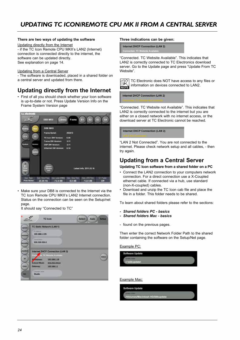
There are two ways of updating the softwareUpdating directly from the Internet-iftheTCIconRemoteCPUMKII’sLAN2(Internet)connection is connected directly to the internet, the software can be updated directly. See explanation on page 14.
Updating from a Central Server- The software is downloaded, placed in a shared folder on a central server and updated from there.
Updating directly from the Internet• FirstofallyoushouldcheckwhetheryourIconsoftwareisup-to-dateornot.PressUpdateVersionInfoontheFrameSystemVersionpage
• MakesureyourDB8isconnectedtotheInternetviatheTCIconRemoteCPUMKII’sLAN2Internetconnection.Status on the connection can be seen on the Setup/net page.
Itshouldsay“ConnectedtoTC”
Three indications can be given:
“Connected.TCWebsiteAvailable”.ThisindicatesthatLAN2iscorrectlyconnectedtoTCElectronicsdownloadserver. Go to the Update page and press “Update From TC Website”.
TC Electronic does NOT have access to any files or informationondevicesconnectedtoLAN2.
“Connected.TCWebsitenotAvailable”.ThisindicatesthatLAN2iscorrectlyconnectedtotheinternetbutyouareeither on a closed network with no internet access, or the download server at TC Electronic cannot be reached.
“LAN2NotConnected”.Youarenotconnectedtotheinternet. Please check network setup and all cables, - then try again.
Updating from a Central Server Updating TC Icon software from a shared folder on a PC• ConnecttheLAN2connectiontoyourcomputersnetwork
connection. For a direct connection use a X-Coupled ethernet cable. If connected via a hub, use standard (non-X-coupled) cables.
• DownloadandunziptheTCIconcabfileandplacethefile in a folder. This folder needs to be shared.
To learn about shared folders please refer to the sections:
- Shared folders PC - basics - Shared folders Mac - basics
- found on the previous pages.
Then enter the correct Network Folder Path to the shared folder containing the software on the Setup/Net page.
Example PC:
ExampleMac:

25
basIC OperaTIOn
IntroductionThis section of the manual is a general introduction to operateDB8/DB4viatheSoftwareEditorortheTCIcon.ThebasicDB8/DB4consistsofaMainframewithaDSPcard and up to three I/O cards, plus a PC Editor but the DB8/DB4canalsobecontrolledviaaTCIconhardwareremote. Severalmainframes,Mac/PC’swithinstalledSoftwareEditor and TC Icons can be hooked up at the same time viaastandardLocalAreaNetwork(LAN).
Accessing a MainframeFirst timeyouconnecttheMainframetothePCwithinstalled PC editor and network adapter:
• PowerupyourcomputerandyourDB8/DB4.• StarttheSoftwareeditorandthefollowingpageappears:
• PressAssign• AllconnectedDB8/DB4mainframeswillbedetectedand
assigned to one of the 8 locations (see fig. 1).• PresstheDB8/DB4icontoaccesstheDB8/DB4.
Scanning the systemThe scenario described above covers the first time you boot up your system or when no connected units are assigned. To scan the system for all connected units, go to the Setup page and press Detect (see fig 2). The connected mainframes will the appear in the left side of the display, and you can assign them to any of the 8 locations illustrated in the right side of the display by selecting the frames with the cursors followed by pressing one of the oval keys.
Engine Structure ThecoreelementofDB8/DB4istheEnginestructure.This structure enables you to run up to two/four powerful algorithms/presets simultaneously. Each Engine is capable of utilizing up to 8 Inputs and 8 Outputs, depending on the selected algorithm/preset. Up to 16 physical Input and 16 physical Output channels can be routed in the most flexible way.
Engine ResourcesThe powerful and flexible DSP distribution structure lets you run up to 4 Engine presets at the same time using any available algorithms.
Basic TC Icon operationNavigation in the Software Editor or TC Icon display is easy as soon as a few basic elements are explained. The Icon Link key in the upper left corner allows you to navigate between the two pages/modes illustrated below.
Generally :•Pressthetop-tabstodoprimaryselections• Presstheside-tabsorelementstodosecondary selections.
Fig 1
Viathe“overall”Select & Setup pages you access overall settings and choices like:• Selectionofwhichmainframetooperate• Enabledevicestonetwork• Updatesviadisk• TCIconsettingssuchasdisplayappearance• SMPTEAutomation
Fig 2
The selection of mainframe is done in the Select page illustratedin“Fig1”.Thepage/pagesillustratedinFig.2are pages containing parameters on a specific mainframe. These are the Operating Pages and the page you will be working in once the system is up and running. Only when several mainframes are connected you will need to go to the“overall”SelectandSetuppagestoswitchmainframe.
op
er
at
ion
26
basIC OperaTIOn
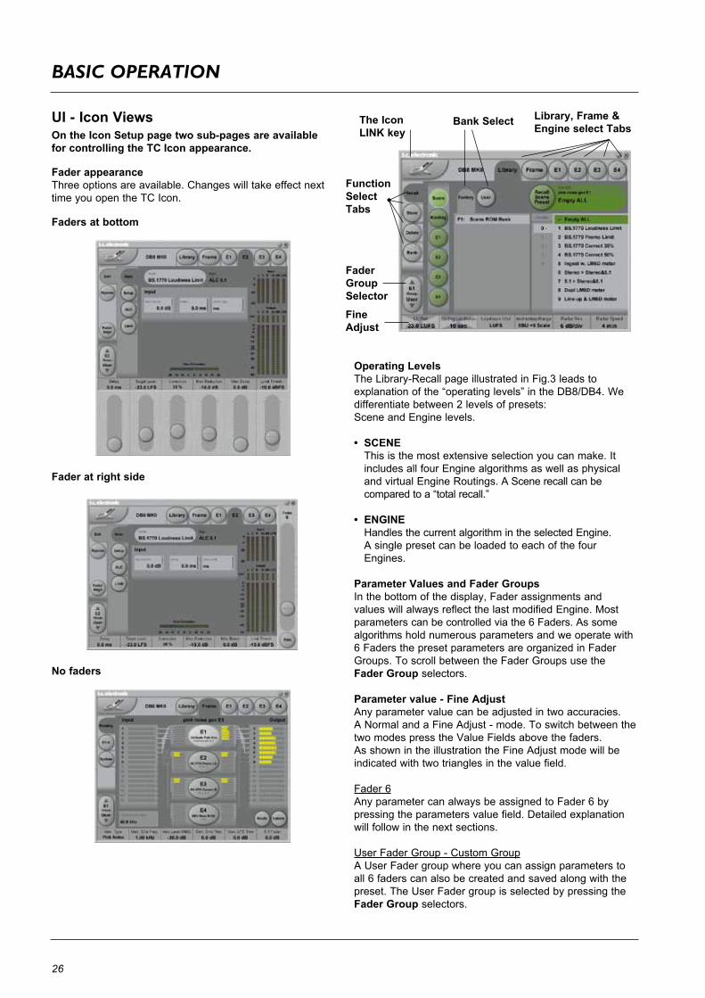
UI - Icon ViewsOn the Icon Setup page two sub-pages are available for controlling the TC Icon appearance.
Fader appearanceThree options are available. Changes will take effect next time you open the TC Icon.
Faders at bottom
Fader at right side
No faders
Operating LevelsTheLibrary-RecallpageillustratedinFig.3leadstoexplanationofthe“operatinglevels”intheDB8/DB4.Wedifferentiate between 2 levels of presets: Scene and Engine levels.
• SCENE This is the most extensive selection you can make. It
includes all four Engine algorithms as well as physical and virtual Engine Routings. A Scene recall can be comparedtoa“totalrecall.”
• ENGINE Handles the current algorithm in the selected Engine. A single preset can be loaded to each of the four Engines.
Parameter Values and Fader GroupsIn the bottom of the display, Fader assignments and valueswillalwaysreflectthelastmodifiedEngine.Mostparameters can be controlled via the 6 Faders. As some algorithms hold numerous parameters and we operate with 6 Faders the preset parameters are organized in Fader Groups. To scroll between the Fader Groups use the Fader Group selectors.
Parameter value - Fine AdjustAny parameter value can be adjusted in two accuracies.A Normal and a Fine Adjust - mode. To switch between the twomodespresstheValueFieldsabovethefaders.As shown in the illustration the Fine Adjust mode will be indicated with two triangles in the value field.
Fader 6Any parameter can always be assigned to Fader 6 by pressing the parameters value field. Detailed explanation will follow in the next sections.
User Fader Group - Custom GroupA User Fader group where you can assign parameters to all 6 faders can also be created and saved along with the preset. The User Fader group is selected by pressing the Fader Group selectors.
Fader GroupSelector
Function SelectTabs
Library, Frame & Engine select Tabs
The Icon LINK key
Bank Select
Fine Adjust

27
lIbrary - reCall
op
er
at
ion
Library RecallOn the Library Recall page the following banks are available for recall operations:
SceneGives access to the following preset banks:• Factory• User• Card(optional)
Engine 1-4Gives access to the following preset banks:• Factory• User• Card(optional)
RoutingGives access to the following preset banks:• Factory• User• Card(optional)
Operation Level Tabs Bank Selectors
Function Select Tabs
Library, Frame and Engine selectors
Parameter Fader values present in the last modified Engine.
Press “info” for preset information
Fader GroupSelector
Decade selector(“tens”)
Recalling a Scene, Routing or Engine preset• PresstheRECALLtabtoselecttheRecallpage.• Nowselectthelevelof:Scene,RoutingorEngine1-4.• Selectwhichbankyouwishtorecallfrom:FactoryorUser.IfaDB8/DB4formattedPCMCIAcardisinsertedintheMainframecard-bankswillbeavailableanddisplayedbelow the User banks.
• Selectpresetspressing:Bank,Decade(tens)andpresetnumber.
(grayed out numbers indicates that the Decade is empty)• PresstheRecall key to recall/load the preset.
InfoForpresetscarryingthe“info”tagwehaveaddedrelevantinformation for the specific preset. Press Info and a pop-up display will appear.
Example:
28
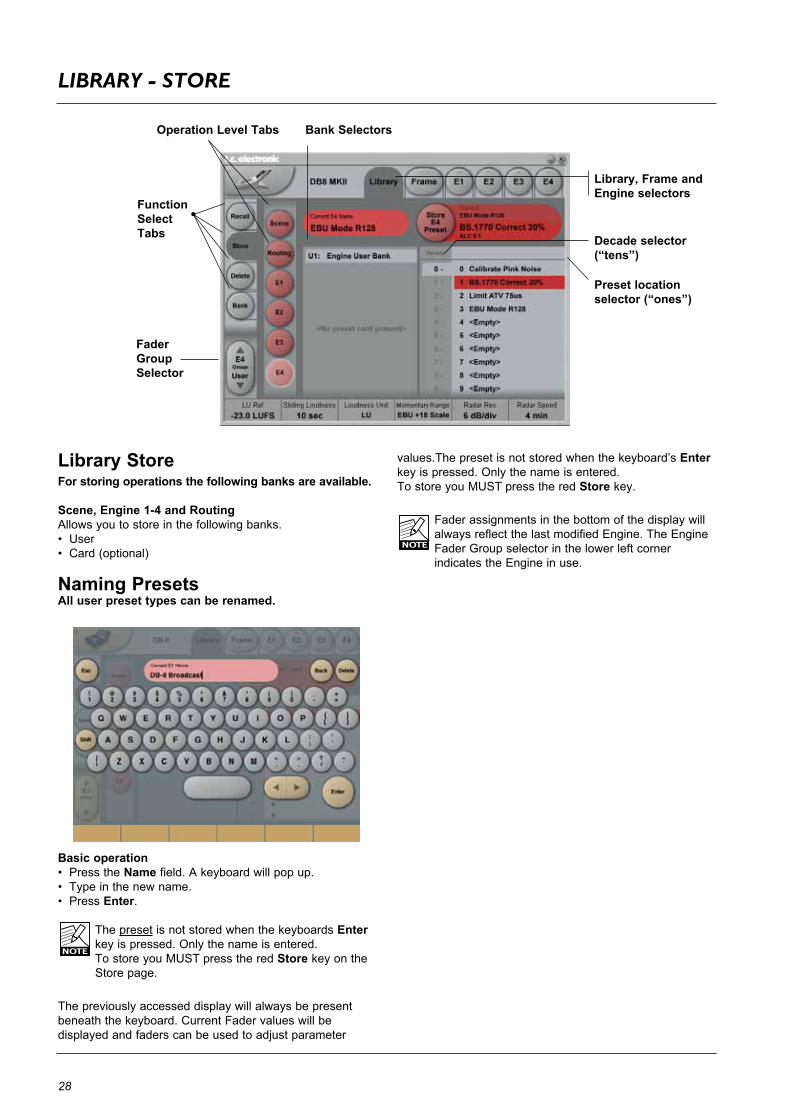
lIbrary - sTOre
Library Store For storing operations the following banks are available.
Scene, Engine 1-4 and RoutingAllows you to store in the following banks.• User• Card(optional)
Naming PresetsAll user preset types can be renamed.
Basic operation• PresstheName field. A keyboard will pop up. • Typeinthenewname.• PressEnter.
The preset is not stored when the keyboards Enter key is pressed. Only the name is entered.TostoreyouMUSTpresstheredStore key on the Store page.
The previously accessed display will always be present beneath the keyboard. Current Fader values will be displayed and faders can be used to adjust parameter
values.The preset is not stored when the keyboard’s Enter key is pressed. Only the name is entered. TostoreyouMUSTpresstheredStore key.
Fader assignments in the bottom of the display will always reflect the last modified Engine. The Engine Fader Group selector in the lower left corner indicates the Engine in use.
Operation Level Tabs Bank Selectors
Library, Frame and Engine selectors
Function Select Tabs
Fader GroupSelector
Decade selector(“tens”)
Preset locationselector (“ones”)

29
lIbrary - banK
op
er
at
ion
Library - BankFrom the Library Bank page you can copy Scene, Routing and Engine banks to and from PCMCIA card or to and from your hard disk when using a TC Icon Editor.
Basic OperationBankcopyingishandledasacompleteUserbanktransferal.
• PressScene, Routing or Engine to select preset bank type.
• Select“from”and“to”dependingonyourchoice.• PressCopy Bank.
Scene/Routing/Engine BanksTo/From-Bank/FileScene, Routing or Engine banks can be backed up and retrievedfromaPCMCIAorafilelocationonaconnectedcomputer (when using the TC Icon software editor).
Copy BankPress to activate copy function between the selected Banks.
RenamePress to rename selected bank via the Naming pop-up display.
DeletePresstocleartheselectedBank.Youwillbeaskedtoconfirm your choice to avoid unintended deletion.
Using PCMCIA cardsTouseaPCMCIAcardwithDB8-DB4thecardmustbeproperly formatted. This is done from the Frame/System/Card page.
A1MBPCMCIAcardcanhold: 1000 Engine presets in 10 banks of 100 presets500 Routing presets in 10 banks of 50 presets500 Scene presets in 10 banks of 50 presets
A512kBPCMCIAcardcanhold:500 Engine presets in 5 banks of 100 presets250 Routing presets in 5 banks of 50 presets250 Scene presets in 5 banks of 50 presets
30
lIbrary - DeleTe
Library - DeleteFor convenience it is possible to “clean up” the User banks by deleting individual presets.
Deleting a Preset• SelectDelete (side tab) and select level by pressing Scene or Engine.• SelectthepresettodeletebypressingtheactualBank,
Decade(to select tens) and the actual preset.• PresstheDelete key to delete the preset.
Library, Frame and Engine selectors
Function Select Tabs
Fader GroupSelector
31
rOuTInG - paGe
op
er
at
ion
Routing
IntroductionTheRoutingpageisthepatchbayoftheDB8/DB4Mainframe.AllroutingsofphysicalInputs/Outputsaswellas internal routing between Engines is setup here.The understanding of this page is therefore essential to operatingtheDB8/DB4.
To access the Routing Page:• PressFrame (upper tab)• PressRouting (side tab)• PressRoute to enable routing facilities
This is the page where you:• HavetheoverallviewofallI/O’s• RoutephysicalInputstoEngineInputs• RouteEngineOutputstophysicalOutputs• AccessInputandOutputmeters
Routing Inputs• PresstheRoute key to select route operation.• PressEngine1-4toselecttheEngineyou wish to route • SelectaphysicalInputoranotherEngine’sOutputusing Fader 1• SelectEngineInputusingFader 2
Routing Outputs• PresstheRoute key to select Route operation• PressEngine1-4toselecttheEngineyouwishtoroute• SelectanEngineOutputusingFader 5• SelectPhysicalOutputusingFader 6
The I/O possibilities are as follows• ItispossibletorouteanInputtoseveral Engine Inputs (up to 32), however, it is not possible to connect more than one physical Input to the same Engine Input.• ItispossibletoconnectallEngineOutputs(upto32)to one single physical Output. •ItispossibletoconnectanEngineOutputtotheInputs of the three other Engines.
Engine Processing DelayProcessing delay between the routed Engines behaves as if they were external devices.
LabelsThe Input/Output fields can show either meters or the Labels/namesontheInput/Outputchannels.Toswitchbetweenthetwomodes,press“Labels”.
Renaming Physical Inputs and OutputsInput and Output channels can be labeled individually. This is a global renaming process and is accessed by pressing System (side tab) followed by I/O and Labels.
MetersEngine I/O MetersEngine I/O meters are shown at the left and right of the large E 1-4 buttons in the middle of the display. The number of meters shown will always reflect the number of I/O channels in the loaded algorithm.
Frame - E1 to E4/E2 (DB8/DB4)
This page holds the User group parameters for all four Engines. Selecting User group parameters is done from the Enginepages.ValuescanbealteredfromboththeEngineEdit pages and the page displayed above. Press the parameter you wish to assign to the Fader located below.

32
frame - sysTem - maIn
State
Clock MasterSets the master clock of the processor. A machine with SDI option always expects an SDI input signal. If SDI is not available, the machine reverts to 48 kHz internal rate operation, which should be regarded an error condition.
Clock FallbackDetermines how the processor reacts if it looses external reference.If“Halt”isselected,signalprocessingstops.If“Internal”isselected,theclockswitchestotheselectedInternal Clockrate in case of lost external reference.
Internal Clock RateThe internal Clock Rate can be set to 44.1 or 48 kHz.Asitisconsidered“unconventional”tousetheDB8internalclock in broadcast setups, a yellow indication will appear on the frame select page when internal is selected.
Clock StatusLocked Clock RateTheClockRatetowhichtheMainframeiscurrentlylocked.
Color indicationsThe yellow color indicates that:- Auto Revert to Internal is selected and...- theselectedClockMasterhasbeenpresentatonepoint but is now lost and...- the frame has switched to the selected internal clock rate.
Theredcolorindicates“nolock”-checkcablesandclocksource.
Detected Sample RateThis is a read-only parameter indicating the actual incoming Sample Rate. The tolerance of this detection is +/- 10Hz.
Example: An incoming Sample Rate of 44.056kHz will be detected as approx. 44.06kHz and the system indicates the Locked Clock Rate 44.100kHz.The system will lock to and reject jitter at any Sample Rate between:
• 42.5-45.5kHz• 46.5-48.5kHz
Power StateDisplay Power StateOff – No indication at power failure
Error – Failure of one power connection indicated by a red indicator on the Frame tab.
Warning – Failure of one power connection indicated by a yellow indicator on the Frame tab.

33
frame - sysTem -maIn -GpI
op
er
at
ion
DB4 and DB8 GPI SpecificationDB4andDB8offersaGPIinputforremoteswitchingbetweenScenes(allEnginePresetsplusRouting).Theinputcanbe used for daily operation, or for backup and redundancy purposes. It allows change between 2, 4 or 8 presets using justoneconnection.GPIfunctionalityincludestwoflexiblemodes(“3presets”and“7presets”)wherenormaleditingofpresets is allowed unless the GPI input is moved away from its idle state. These modes are typically be used for putting the machine into a defined state, for instance for backup or emmergency announcements overruling normal operation. GPI switchingis“intelligent”andperformedwithoutaudiointerruptionaslongasthesamealgorithmsareusedinEngine1-4,and only parameters are changed.
Basic operationGPIfunctionsareaccessedfromtheSystem/Main/GPIpageinTCIcon.
Enable Recall
Off
2 Presets
3 Presets
4 Presets
7 Presets
8 Presets
Notes
Makesurethisstateisselected,ifGPIrecallisnotbeingused.
User Scene 0 or 1 is permanently recalled. Note: Switching to this mode will instantly perform a Scene Recall, even if no connections are made to the GPI input.
AslongastheGPIinputisidle(+5V),GPIrecallisinactive.Inidlemode, the machine can be normally controlled from Icon, or using the serial data input.If active GPI windows 1, 2 or 3 are selected, the corresponding Scene is recalled, and the serial data control inputisdisabled.ThisGPImodeissuitableforBackupandAlarmmessaging operation.
User Scene 0, 1, 2 or 3 is permanently recalled. Note: Switching to this mode will instantly perform a Scene Recall, even if no connections are made to the GPI input.
AslongastheGPIinputisidle(+5V),GPIrecallisinactive.Inidle mode, the machine can be normally controlled from Icon, or using the serial data input.If active GPI windows 1-7 are selected, the corresponding Scene is recalled, and the serial data control inputisdisabled.ThisGPImodeissuitableforBackupandAlarmmessaging operation.
User Scene 0, 1, 2, 3, 4, 5, 6 or 7 is permanently recalled. Note: Switching to this mode will instantly perform a Scene Recall, even if no connections are made to the GPI input.
The Enable Recall parameter can be set to Off (GPI recall disabled), 2, 3, 4, 7 and 8 presets.Presets are selected as a state condition, i.e. presenting the GPI input a permanent voltage signifying a specific preset.Seetablebelowfordescriptionof“EnableRecall”set-tings.NOTE:Moving“EnableRecall”awayfromtheOffposition immediately results in a Scene preset recall, and locks the machine from editing of parameters or recall of other presets.
The“SelectBetweenScenes”parametersetsthepresetrange from which presets are recalled based on GPI commands.Forinstance,ifsetto“10-19”,GPIcom-mands recall a User Scene preset in the range 10-19. If “EnableRecall”issetto“4presets”,theGPIinputthusselects between User Scene preset 10, 11, 12 and 13.

34
frame - sysTem -maIn -GpI
InstallationSelectionbetweenupto8presetsisachievedbyfeedingtheprocessoraDCvoltagetothe1/4”jackinputlabeled“Pedal”.The input voltage is compared against voltage windows that correspond to certain presets.Betweenthevalidvoltagewindows,invalidwindowshavebeeninsertedtoprotectagainsterraticoperation.Theprocessorconstantly monitors the GPI input, and only if several consecutive measurements point to the same, valid voltage window, a recall is performed.Thevoltagewindowschosenenableeasy“binaryrelayencoding”asshowninfig.1.Iflongcablerunsarerequired,HFdecoupling using a ceramic capacitor across the Tip and Sleeve terminals inside the jack plug may be indicated.
Note: The ring terminal of the 1/4” jack is not used.
Fig 1, Relay coding of 2, 4 and 8 preset GPI configurations

35
frame - sysTem -maIn -GpI
op
er
at
ion
GPI Technical specificationsInsidetheprocessor,a10kohmresistorconnectstheTipterminaltoa+5Vpowersupply.WhennothingisconnectedtotheGPIinput,theinputvoltagethereforeis+5V.ResistorscanbeusedtopulldownthevoltageassuggestedinFig1.In Table 1, voltages outside the limits mentioned are to be considered invalid. No action is taken if invalid measurements are made. GPI recall action resumes when a stable, valid measurement again is detected.
Mode
1 of 2
1 of 4
1 of 8
Preset No
01
0123
0123456
Target / Vs
1.000 (idle)0.000
1.000 (idle)0.6870.5450.438
1.000 (idle)0.8240.6870.6000.5450.4890.4370.400
Target typ / V
5.000.00
5.003.442.732.19
5.004.123.443.002.732.442.192.00
Max typ / V
5.000.51
5.003.502.792.25
5.004.183.503.062.792.502.252.06
Min typ / V
2.670.00
4.163.382.670.00
4.504.063.382.942.672.382.130.00
Tech Notes:“Idle” refers to the state when no input is connected, or when the input is left floating.
Rather than absolute voltage measurements, the windows are defined as a fraction of the supply voltage, Vs. This voltage can be measured with a high impedance DMM on the Tip terminal when no pull down resistors are applied.
The table shows values as a fraction of Vs, and, as a guideline, typical voltages when Vs=5.000V. (If the Supply voltage is e.g. 5.015V, the table should be corrected by multiplying these values by 5.015/5).
36
frame - sysTem - maIn - mIDI
Normal modeIn Normal mode all banks can be accessed for program changes.BankselectionisdoneviaCtrl0(MSB)andCtrl32(LSB):
• Controller0mustbesetto0inallcases.• Controller32valuemustmatchthebanknumberyou
wish to address according to the table below.
Ctrl 32 value 0 - F1: Loudness, StereoCtrl 32 value 1 - F2: Loudness, MultichannelCtrl 32 value 2 - F3: ReservedCtrl 32 value 3 - F4: Format ConversionCtrl 32 value 4 - F5: ReservedCtrl 32 value 5 - F6: Delay and EQCtrl 32 value 6 - F7: ReservedCtrl 32 value 7 - F8: Monitor and LineupCtrl 32 value 8 - F9: ReservedCtrl32value9 - F10: MeteringCtrl 32 value 10 - F11: ReservedCtrl 32 value 11 - F12: ReservedCtrl 32 value 12 - F13: ReservedCtrl 32 value 13 - F14: Reserved
Ctrl 32 value 32 - User bank
Ctrl32value64 - CardBank1Ctrl32value65 - CardBank2Ctrl32value66 - CardBank3 - - - - -Ctrl32value73 - CardBank10
Example:Youwishtorecallpreset5fromtheLoudness,Stereobank. According to the table above:• SetCtrl0to“0”andCtrl32to“0”andsendprogram
change no 5.
SysEx Device IDRange: 0 to 126SelectSysExIDfortheMainframe.
MIDI RateRange: Normal or 19.2ThisparametersetstheBaudRate/MIDItransferrate.Thedefaultsettingis“Normal”.However,“19.2”maybebetter suited for external master control programs as found in broadcast stations.
MIDI Setup Page
IntroductionMIDI ChannelsTo recall presets for Scene, Routing and Engines 1 to 4 youmustfirstsetupindividualMIDIchannelsforthesecategories. IntheexampleaboveMIDIchannels1to4arsetupforEngines 1 to 4 respectively and channel 5 to access Scene presets and channel 6 to access Routing presets.
Bank ModeTheBankmodesettingsdeterminethedestinationbankofthereceivedprogramchangeonthespecifiedMIDIchannels.
Normal mode: ThismoderequiresthattheexternalsendingMIDIdevicecansendbothController0and32inadditiontoMIDIprogram changes. This is an essential feature to recall presets from a device holding more than 128 preset locations. (see table in next column for details)
Factory and User mode:These modes will force any incoming program change to access either Factory or User banks directly and are typicallyusedifyoursendingMIDIdevicecannotsendControllers 0 and 32 as described above.
37
frame - sysTem - maIn - mIDI
op
er
at
ion
MIDI Control Page
On the MIDI Control Page the following options are available:
Read Program ChangeSelect whether the Frame should read incoming program changes or not.
Send Program ChangeSelect whether the Frame should send program changes to MIDIoutwhenpresetsarerecalledviaTCIconortheTCIcon Software editor.
Read Control ChangeSelect whether the Frame should Read Control Changes messages.
Send Control ChangeOptions here are Single (7 bit) or Double (14 bit) precision.
Read SysEx - Send SysExThese two parameters determine whether the Frame should read and send SysEx.
MIDI DUMP Page
VariousoptionsforMIDIinformationdumpisavailable.
Dump Scene - includes both routing and all presets loaded in the Engines.
Dump Routing - dumps current routing presets.
Dump E1-E4 - Dumps all currently loaded presets in all four Engines.
Dump E1, Dump E2, Dump E3, Dump E4 - Individual dump from each Engine with the currently loaded algorithms.

38
frame - sysTem - maIn - neT/CarD
Net
Network IdentifierPressthefield“NetworkIdentifier”toenteranamefortheMainframe.ThisistheglobalTCnetworknamefortheframe.Bygivingtheframeaspecificnameitwillbeeasierto identify the frame when hooked up in a network with several frames.
Card
Format card with empty preset banksThisfunctionwillformataPCMCIAcardwithDB8/DB4presetbanks.Aformatted1Mbcardwillhold:
• 10Engineusercardbanksof100presets• 10Routinguserbanksof50presets• 10Sceneuserbanksof50presets
Youmayalsochoosetoformatandpreparea1MbcardforAutomationLists.

39
frame - sysTem - I/O
op
er
at
ion
I/O - DSP - SDI card installed
Input SelectSelectbetweenSDIinputsAorB
Input/Output channels 1-4/5-8Use the Input/Output parameters to select which SDI Groups become available on the Routing display of the processor.
Group 1-4 indicatorsThese“LEDs”indicatewhichSDIInputGroupshaveaudioavailable.
Locked Clock RateThis information field displays the currently locked Clock Rate, which is always 48 kHz when the processor is used with SDI.
FrequencyThis information field displays the SDI Input data rate in a rangebetween140Mbpsand1.5Gbps.
I/O - Setup - AES card installed
This page indicates the frame’s current card configuration.
I/O - DSP - AES card installed
This page indicates current status on the DSP card.- Dither for AES pairs can be set to 24-20-18-8
I/O - Setup - SDI card installedI/O Setup pageSetup page with SDI installed.The Frame-System-I/O-Setup appears as illustrated below when a SDI card is installed.
40
frame - sysTem - I/O
FormatThis information field displays the SDI Input format.A partial list of SDI formats handled and recognized by DB4/8:
Format LatencySD 29.97 85/1.77SD 25 87/1.811280x720/60p 38/0.791280x720/59.94p 38/0.791280x720/50p 39/0.811280x720/30p 38/0.791280x720/29.97p 38/0.791280x720/25p 39/0.811280x720/24p 39/0.811920x1080/30p 40/0.831920x1080/29.97p 40/0.831920x1080/25p 42/0.881920x1080/24p 42/0.881920x1080/60i 40/0.831920x1080/59.94i 40/0.831920x1080/50i 42/0.881920x1080/25i 42/0.88
I/O - A/B/C
Input, Output and Dither settings for e.g. an SDI 8 cardplacedinslotB/CaswellasLockedClockRate,Frequency and Format indication
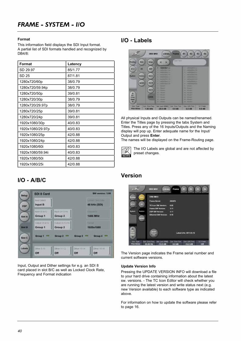
I/O - Labels
All physical Inputs and Outputs can be named/renamed. Enter the Titles page by pressing the tabs System and Titles. Press any of the 16 Inputs/Outputs and the Naming display will pop up. Enter adequate name for the Input/Output and press Enter. The names will be displayed on the Frame-Routing page.
TheI/OLabelsareglobalandarenotaffectedbypreset changes.
Version
TheVersionpageindicatestheFrameserialnumberandcurrent software versions.
Update Version InfoPressingtheUPDATEVERSIONINFOwilldownloadafileto your hard drive containing information about the latest sw. versions. - The TC Icon Editor will check whether you are running the latest version and write status next (e.g. newVersionavailable)toeachsoftwaretypeasindicatedabove.
For information on how to update the software please refer to page 16.
41
op
er
at
ion
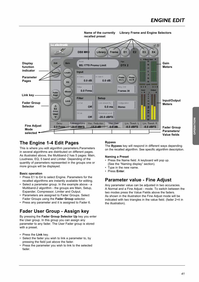
enGIne eDIT
Fader Group Parameters/Value fields
Input/Output Meters
Display functionindicator
Gain Meters
Library Frame and Engine SelectorsName of the currently recalled preset
Fader GroupSelector
Parameter Pages
Link key
Fine Adjust Mode selected
The Engine 1-4 Edit PagesThis is where you edit algorithm parameters.Parameters in several algorithms are distributed on different pages. Asillustratedabove,theMultiband-2has5pages:Main,Loudness,EQ,5bandandLimiter.Dependingofthequantity of parameters represented in the groups one or more groups will be displayed.
Basic operation• PressE1toE4toselectEngine.Parametersforthe recalled algorithms are instantly available for editing.• Selectaparametergroup.Intheexampleabove-aMultiband-2algorithm-thegroupsareMain,Setup,Expander,Compressor,LimiterandOutput.
• ParametersareassignedtoFaderGroups.Select Fader Groups using the Fader Group selector.• PressanyparameteranditisassignedtoFader6.
Fader User Group - Assign keyBypressingtheFader Group Selector Up key you enter the User group. In this group you can assign any parameter to any fader. The User Fader group is stored with a preset.
• PresstheLink key.• Selectthefaderyouwishtolinkaparameterto,by
pressing the field just above the fader.• Presstheparameteryouwishtolinktotheselected fader.
BypassThe Bypass key will respond in different ways depending on the recalled algorithm. See specific algorithm description.
Naming a Preset• PresstheNamefield.Akeyboardwillpopup. (Seethe“Namingdisplay”section).• Typeinthenewname.• PressEnter.
Parameter value - Fine AdjustAny parameter value can be adjusted in two accuracies.A Normal and a Fine Adjust - mode. To switch between the twomodespresstheValueFieldsabovethefaders.As shown in the illustration the Fine Adjust mode will be indicated with two triangles in the value field. (fader 2+4 in the illustration).

42
ICOn seTup
Icon User Interface(only available on the hardware version of the TC Icon)
Go to the Select & Setup pages pressing the TC Icon key in the upper left corner.Press SETUP (upper tab) and UI (side tab) to enter the setup page for the TC Icon display.
TC Icon Display ParametersIn this display, you set up various parameters regarding the appearance of the display as well as the Fader Touch Sensitivity.
Display BrightnessAdjust the brightness of the display using either the Arrow cursors or simply drag the “Adjusthandle”.
Show Mouse CursorPress to show mouse/pointer position.
Calibrate Display TouchFor optimal performance the touchscreen will at times need to be calibrated. Press and follow instructions to calibrate the touchscreen.
Fader SensitivityTo avoid accidental movement of the faders, they are sensitive to humidity and will only respond when touched by your skin.
Enable Fader TouchEnables touch sensitivity of the Faders.
AC/DC SensitivitySets the Faders, sensitivity to AC and DC. Adjust these handles to achieve optimal performance in your environment.
Software Editor Setup menu
InfoOn this page, the current Software Editor version number is listed.
DevicesOn this page you control and assign the devices in the setup.
• Press Detect to scan the network for connected devices. All devices will appear in the list. • Nowassignthedevicesoneatatimebyselectingthe
device using the Cursor up/down followed by pressing one of the eight oval keys in the right side of the display.
SecurityIn the security page you can activate/deactivate the “sticky clip”function.Whenthisfunctionissetto“on”theOverloadLEDsontheRouting page will stay lit once activated, until the Reset Clip key is pressed.
ColorSelect the Color scheme of your choice. Depending on the surrounding light conditions, different schemes may be more appropriate than others.

43
op
er
at
ion
smpTe
SMPTE
Reader EnabledOn/OffswitchfortheDB8/DB4SMPTEReader.
Frame RateRange: 24 FPS, 25 FPS, 29.97 FPS, 30 Drop FPS, 30 FPS.
Running StatusThe small field in the top left corner of the numeric display willstate“Running”whenSMPTEclockisrunning.
Auto Edit Page
In the Auto Edit page, all automation Events are listed and handled.
KeepPresstosavetheEventListlocallyontheIcon.ItispossibletosaveoneEventListontheIcon.Additionalcue-listscanbestoredandrecalledonaPCMCIAcard.The Keep key will turn red as soon as any editing of the list has taken place, indicating that you must press to save the list.This key corresponds/is the same, as the Keep key located on the File page. (see following page)
WriteWhen enabled, any program change is written to the SMPTEEventList.ThiscanbeEngine,RoutingorScenerecalls.
ReadWhen enabled, the Event list will be executed according to incomingSMPTEclock.ReadandWritefunctionscanbeactivated simultaneously.
General Read and Write status is given in the Icon Tab in the left corner.
FollowWhen Follow is selected the list will scroll and the current event/song position will always be in the top line.When Follow is de-selected the list will NOT scroll but the cursor position will move according to song-position.
ModifyPress this key to access Event parameters for the currently selected Event. (see further description below)
DeletePress to delete the selected Event.
Event ParametersFor each Event the following parameters are available.
Time - indicatestheSMPTEtimeatwhichtheEvent takes place.Device - indicatingonwhichDeviceMainframethe Event is taking place. Device numbers 1-8, corresponds to the Device position at the Select page.Event - states the occurring Event at the given time.
Insert New EventPress to insert an Event (see further description below)
CursorThe triangular cursor always indicates the current clock positioninrelationtotheEventList.
Modify/Insert Page

44
smpTe
Event SettingsOperation• ToaccessEventsettings,pressModify in the Edit page.• SetupallparametersfortheEventyouareaboutto ModifyorInsert.• PressOKtoconfirm.
TimeThetimewheretheEventbeingModifiedorInsertedis taking place.
Step/AdjustRange: Frame, 1 Second, 10 Seconds, 1 min., 10 min. or 1 hour.Use the Step parameter to select Adjust range and the Adjust parameter to increase/decrease the time.
DeviceThisparameterselectswhichMainframeconnectedtotheLANyouareworkingon.Devicenumbers1-8,correspondsto the Device position at the Select page.
Preset TypeSelects whether the preset Event you are working on is a Scene, Routing, Engine or a System preset.
BankSelect the bank related to the preset you are about to setup/recallviaSMPTE.
PresetSelect the preset from the selected bank.
File
Current ListKeepPresstosavetheEventListlocallyontheIcon.ItispossibletosaveoneEventListontheIcon.Additionalcue-listscanbestoredandrecalledonaPCMCIAcard..The Keep key will turn red as soon as any editing of the list has taken place, indicating that you must press to save the list.This key corresponds/is the same, as the Keep key located on the Edit page. (see previous page)
RevertThis“Undo”functionallowsyoutorevertthetothelastsavedSMPTEEventlist.ThisistheListthatisstoredlocally on the TC Icon.
ClearPress CleartodeletetheentireSMPTEEventlistpresentin the TC Icon.
File StorageEvent lists can easily be organized and saved to a PCMCIAcardintheMainframe.Mainframeselectionisdone in the Auto Edit page.
PCPresstogetalistofallSMPTEEventlistsstoredontheconnected computers hard drive.CardPresstogetalistofallSMPTEEventlistsstoredonaPCMCIAcard.
NewPress New to create and name a new Event list.
SavePress to save the current Event list.
LoadPress to load Event list.
DeletePress to delete selected Event preset from the Event Preset list.

45
smpTe
Options
Automation Timecode OptionsMaster Sync DeviceSelectwhichoftheMainframesconnectedontheLANyouwishtoactasMasterClock.
Start Of DaytimeRange: 23:00:00:.00 or 00:00:00:00IftheSMPTEtimecodepresentonyourtapemediaorfilmdoes not start exactly at the beginning of the tape, the 23:00:00:00 setting would be a good choice to keep chronologicalorderintheEventList.
Support of SNMPMultipleDB8and/orDB4unitscanbemonitoredusingindustrystandardSNMPtrapping.SNMPincludesmonitoring of sync status, overload, silent outputs and more.-Lookonwww.tcelectronic.comunder“Products-DB8/DB4”fordetails.
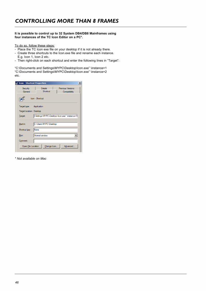
46
COnTrOllInG mOre THan 8 frames
It is possible to control up to 32 System DB4/DB8 Mainframes using four instances of the TC Icon Editor on a PC*.
To do so, follow these steps:- Place the TC Icon exe file on your desktop if it is not already there.- Create three shortcuts to the Icon.exe file and rename each instance. E.g. Icon 1, Icon 2 etc.- Thenright-clickoneachshortcutandenterthefollowinglinesin“Target”:
“C:\DocumentsandSettings\MYPC\Desktop\Icon.exe”\instance=1“C:\DocumentsandSettings\MYPC\Desktop\Icon.exe”\instance=2etc.
* Not available on Mac

47
ap
pe
nd
ix
lICense aGreemenT
End Users License Agreement (EULA) for TC ICON OS (Operating System) contained in the TC Electronic A/S embedded system: TC ICON/Remote CPU.TheTCICONoperatingsystemisbasedonMicrosoftNT.
Refund IfyoudonotagreetothetermsofthisEULA,TCElectronicA/SandMicrosoftareunwilling to license the TC ICON OS to you. In such event, you may not use the TC ICON/Remote CPU, and you should promptly contact TC Electronic A/S forinstructions on return of the unused products for a refund.
Client Access LicensesIf you use the TC ICON/Remote CPU to access or utilize the services or functionality of MicrosoftWindowsNTServer(alleditions)orusetheTCICON/RemoteCPUtopermitworkstation or computing devices to access or utilize the services or functionality of MicrosoftWindowsNTServer,youmayberequiredtoobtainaClientAccessLicenseforthe TC ICON/Remote CPU and/or each such workstation or computing device. PleaserefertotheenduserlicenseagreementforMicrosoftWindowsNTServerforadditional information.
No WarrantiesEXCEPTASEXPRESSLYPROVIDEDINTHELIMITEDWARRANTYSECTIONABOVE,THETCICONOperatingSystemISPROVIDEDTOYOU“ASIS”WITHOUTWARRANTYOFANYKIND,EITHEREXPRESSEDORIMPLIED,INCLUDING,BUTNOTLIMITEDTO,WARRANTIESOFNON-INFRINGEMENT,MERCHANTABILITY,AND/ORFITNESSFORAPARTICULARPURPOSE.THEENTIRERISKOFTHEQUALITYANDPERFORMANCEOFTHETCICONOSISWITHYOU.
No Liability for Consequential DamagesTCElectronicA/S’sSOFTWARESUPPLIERSSHALLNOTBEHELDTOANYLIABILITYFORANYDAMAGESSUFFEREDORINCURREDBYYOU(INCLUDING,BUTNOTLIMITEDTO,GENERAL,SPECIAL,CONSEQUENTIALORINCIDENTALDAMAGESINCLUDINGDAMAGESFORLOSSOFBUSINESSPROFITS,BUSINESSINTERRUPTION,LOSSOFBUSINESSINFORMATIONANDTHELIKE),ARISINGFROMORINCONNECTIONWITHTHEDELIVERY,USEORPERFORMANCEOFTCICON OS.
Customer RemediesTC Electronic A/S’s suppliers entire hability and your exclusive remedy shall be, at TC Electronic A/S’s option, either (a) return of the price paid, or (b) repair or replacement of theTCICON/RemoteCPUthatdoesnotmeettheaboveLimitedWarrantyandwhichisreturnedtoTCElectronicA/Swithacopyofyourreceipt.ThisLimitedWarrantyisvoidif failure of the TC ICON/Remote CPU has resulted from accident, abuse, or misapplica-tion. Any replacement TC ICON/Remote CPU will be warranted for the remainder of the original warranty period or thirty (30) days, whichever is longer.
Limitations on Reverse Engineering, Decompilation and DisassemblyYoumaynotreverseengineer,decompile,ordisassembletheTCICONOS,exceptandonly to the extent that such activity is expressly permitted by applicable law notwithstand-ing this limitation.
Separation of ComponentsThe TC ICON OS is licensed as a single product. Its component parts may not be sepa-rated for use on more than one TC ICON/Remote CPU.
Single TC ICON/Remote CPUThe TC ICON OS is licensed with the TC ICON/Remote CPU as a single integrated product. The TC ICON OS may only be used with the TC ICON/Remote CPU as set forth in these licensing terms.
RentalYoumaynotrent,leaseorlendtheTCICONOS.
TC ICON OS transferYoumaypermanentlytransferallofyourrightssetforthintheselicensingtermsonlyas part of a permanent sale or transfer of the TC ICON/Remote CPU, provided you retain no copies, you transfer all of the TC ICON OS (Including all component parts, the media and printed materials, any upgrades, these licensing terms, and, if applicable, the Certificate(s) of Authenticity), and the recipient agrees to these licensing terms. If the TC ICON OS is an upgrade, any transfer must also include all prior versions of the TC ICON OS.
Back-up CopyIf TC Electronic A/S has not included a back-up copy of the TC ICON OS with the TC ICON/RemoteCPU,youmaymakeasingleback-upcopyoftheTCICONOS.Youmayuse the back-up copy solely for archival purposes. Except as expressly provided in these licensing terms, you may not otherwise make copies of the TC ICON OS.
NOT FAULT TOLERANTTHETCICONOSMAYCONTAINTECHNOLOGYTHATISNOTFAULTTOLERANTANDISNOTDESIGNED,MANUFACTURED,ORINTENDEDFORUSEORRESALEASON-LINECONTROLEQUIPMENTINHAZARDOUSENVIRONMENTSREQUIRINGFAIL-SAFEPERFORMANCE,SUCHASINTHEOPERATIONOFNUCLEARFACILITIES,AIRCRAFTMACHINES,ORWEAPONSSYSTEMS,INWHICHTHEFAILUREOFLICENSEDSOFTWARECOULDLEADDIRECTLYTODEATH,PERSONALINJURY,ORSEVEREPHYSICALORENVIRONMENTALDAMAGE.
TerminationWithout prejudice to any other rights, TC Electronic A/S may terminate this license if you fail to comply with the licensing terms. In such event, you must destroy all copies of the TC ICON OS and all of its component parts.
Note on Java SupportTheTCICONOSmaycontainsupportforprogramswritteninJava.Javatechnologyis not fault tolerant and is not designed, manufactured, or intended for use or resale as online control equipment in hazardous environments requiring fail-safe performance, such as in the operation of nuclear facilities, aircraft navigation or communication systems, air traffic control, direct life support machines, or weapons systems, in which thefailureofJavatechnologycouldleaddirectlytodeath,personalinjury,orseverephysicalorenvironmentaldamage.SunMicrosystems,Inc.hascontractuallyobligatedMicrosoftCorporationtomakethisdisclaimer.
EXPORT RESTRICTIONSExport of the TC ICON OS from the United States is regulated by the Export Administration Regulations (EAR, 15 CFR 730-744) of the U.S. Commerce Department, BureauofExportAdministration(BXA).YouagreetocomplywiththeEARintheexportor re-export of the TC ICON OS: (i) to any country to which the U.S. has embargoed or restrictedtheexportofgoodsorservices,whichasofMay1999include,butnotnec-essarilylimitedtoCuba,Iran,Iraq,Libya,NorthKorea,Sudan,Syria,andtheFederalRepublicofYugoslavia(includingSerbia,butnotMontenegro),ortoanynationalofanysuch country, wherever located, who intends to transmit or transport the TC ICON OS backtosuchcountry;(ii)toanypersonorentitywhoyouknoworhavereasontoknowwill utilize the TC ICON OS or portion thereof in the design, development or production ofnuclear,chemicalorbiologicalweapons;or(iii)toanypersonorentitywhohasbeenprohibited from participating in U.S. export transactions by any federal agency of the U.S. government.YouwarrantandrepresentthatneithertheBXAnoranyotherU.S.federalagency has suspended, revoked or denied your export privileges. For additional informa-tion see http://www.microsoft.com/exporting.
48
TeCHnICal speCIfICaTIOns - frame
PlatformNumber of audio channels: Number of processing engines:Processing Delay:Additional delay:Output Dither:Frequency Response DIO:Internal sample rate:Internal clock precision:Jitterrejectionatexternalsamplerates:Rejection filter (4th order):Rejection filter peak (jitter gain):
PCMCIA InterfaceConnector:Standards:Card Format:
Control InterfaceMIDI:“GPIcontrolinput”Remote:SMPTE:Ethernet,SNMPandremotecontrol:
EMCComplies with:
SafetyCertified to:
EnvironmentOperating Temperature:Storage Temperature:Humidity:
GeneralFront indicators:Finish:Dimensions:Weight:Mainsvoltage:Power supply function:Fan:Power consumption:BackupBatteryLife:Warranty, Parts and labor:
IO configurationsAES balancedNumber of audio channels:Connectors:Formats:Word clock input:Intrinsic interface jitter : Digital output phase:Input variation before sample slip:Interface function:
AES3-id unbalancedNumber of audio channels:Connectors:BypassRelay:Formats:Word clock input:Intrinsic interface jitter: Digital output phase:Input variation before sample slip:Interface function:
SDINumber of audio channels:Connectors:BypassRelay:Function:Formats supported:Input selection:Outputs:Audio embed + de-embed delay:Videodelay:Interface function:
Max16inputs,16outputs4inDB8,2inDB40.15 ms + 0.21 ms per engine @ 48 kHz, 0.07 ms0-4 sec per audio channelHPF/TPDF 8-24 bit and OffDCto23.9kHz±[email protected] kHz, 44.1 kHz+/- 30 ppm42.5 to 45.5 kHz, 46.5 to 48.5 kHz<-3dB@50Hz,<-65dB@500Hz,<[email protected]<1dB@2Hz
PC Card, 68 pin type 1 cardsPCMCIA2.0,JEIDA4.0Supportsupto2MBSRAM
In/Out/Thru: 5 Pin DINChange between 2, 4 or 8 presetsCustomMIDIIn&OutInput for timed program changes10/100Mbits/s,Base-T
EN55103-1andEN55103-2,FCCpart15classB,CISPR22classB
IEC60065,EN60065,UL6500andCSAE65
32° F to 122° F (0° C to 50° C)-22° F to 167° F (-30° C to 70° C)Max.90%non-condensing
PSU 1 OK, PSU 2 OK, Remote CommunicationNatural color anodized aluminum face plate. Painted and plated steel chassis19 x 3.5 x 12 inches (483 x 89 x 305 mm), 2 RU 19 lbs. (8,6 kg) 100to240VAC,50-60Hzauto-selectDual Power Supply RedundancyDual Fan Redundancy25 to 50 W typ., 60 W max, depending on I/O configuration>10 years1 year
8 channel In, 8 channel OutSUB-D,25pole,110Ohm,AES/EBUin/outAES/EBU(24bit)BNC,75OhmorHi-Z,0.6to10Vpp<1nspeak,BW:700Hzto100kHzLessthan3%ofsampleperiod+27%/-73%ofsampleperiodSynchronous, bit transparent
8 channel In, 8 channel OutBNC,75Ohm,0.1to10Vpp,AES3-idin/outInputs to outputs while powered off and during boot-upAES/EBU(24bit)BNC,75OhmorHi-Z,0.6to10Vpp<1nspeak,BW:700Hzto100kHz<3%ofsampleperiod+27%/-73%ofsampleperiodSynchronous, bit transparent
8 channel In, 8 channel Out2BNCIn,2BNCOut.75OhmInputBtooutputwhilepoweredoffandduringboot-upAudio de-embed/embed, video thruSDandHD.143-1485MHzInput 1 or 2, SDI group 1-42 is a replicate of 1. Outputs are individually buffered.1.77 ms @ SD, 0.83 ms @ HD22.3 us @ SD, 15.4us @ HDSynchronous, bit transparent video and audio
Tech
nica
l Spe
cific
atio
ns a
re s
ubje
ct to
cha
nge
with
out n
otic
e !

49
TeCHnICal speCIfICaTIOns - TC ICOn & remOTe Cpu
ap
pe
nd
ix
Technical Specifications are subject to change without notice !
These specifications cover the optional TC Icon remote control
TC Icon MK II
Display Type:
Touch screen:Faders:
Connection:
EMCComplies with:
SafetyCertified to:
EnvironmentOperating Temperature:Storage Temperature:Humidity:
GeneralFinish:
Dimensions:
Weight:
Warranty, Parts and labor:
6,5”TFTactivematrixcolorLCDdis-play, 640 x 480 pixels resolution. High luminance (300 cd/m2, typ.)Resistive, 20 gram activation forceSix (6), 90mm motorized with touch sensitivity36-pinMDRconnectionforRemoteCPU 6000 mk II
EN 55103-1 and EN 55103-2, FCC part15classB,CISPR22classB
IEC60065,EN60065,UL6500andCSA E65
32° F to 122° F (0° C to 50° C)-22° F to 167° F (-30° C to 70° C)Max.90%non-condensing
Natural color anodized aluminum. Stand plate in brushed stainless steelD x W x Hfront x Hback: 11 x 7.8 x 1.3 x 3.9 inches (279 x 198 x 33 x 100 mm) 5.56 Ib (2,51 kg)
1 year
Remote CPU 6000 MK II
CPU:System disc:SystemMemory:
Operating system:
Connections:Ethernet interface:
USBinterface:
COMinterface:
Keyboard/Mouse:External display:Remote:
EMCComplies with:
SafetyCertified to:
EnvironmentOperating Temperature:Storage Temperature:Humidity:
GeneralFinish:
Dimensions:
Weight:MainsVoltage:
Power Consumption:BackupBatteryLife:
Warranty, Parts and labor:
EmbeddedAMDGeodeLX-800,500MHz512MBCompactFlashCard256MBSODIMM200-pinDDRSDRAMWindows Embedded Standard
Twoseparated10/100Mbits/sTCNetwork (fixed IP) and firewalled inter-net network (dynamic IP). Standard IEEE 802.3u protocol compatible on RJ-45connectors.TwoUniversalSerialBusports,USB2.0 compliant (for connection of TCE products,e.g.Reverb4000,DB2)Two RS-232 serial communication ports.SUB-D9pin(forconnectionofTCEproducts,e.g.P2,DB2)Mini-DINconnectorsupportsstandardPC/AT keyboard and a PS/2 mouse.VGAoutput,SUB-D15pin36-pin connection for TC Icon mk II
EN 55103-1 and EN 55103-2, FCC part15classB,CISPR22classB
IEC60065,EN60065,UL6500andCSA E65
32° F to 122° F (0° C to 50° C)-22° F to 167° F (-30° C to 70° C)Max.90%non-condensing
Natural color anodized aluminum face plate. Painted and plated steel chassis19 x 1.75 x 8.2 inches (483 x 44 x 195 mm) 4,8 Ib. (2,2 kg)100to240VAC,50to60Hz(auto-select)50 watts >10 years
1 year
