d:bluebo~1manual~2nuovi ~2s - sklep … · blue box index page sigma 2002 - water chiller 1...
TRANSCRIPT
SIGMA 200242 ÷ 297 kW
00620062006200620062
Water chillersWater chillersWater chillersWater chillersWater chillers Water/waterWater/waterWater/waterWater/waterWater/water Scroll compressorsScroll compressorsScroll compressorsScroll compressorsScroll compressorsself containedself containedself containedself containedself contained
Installation,Installation,Installation,Installation,Installation,operating,operating,operating,operating,operating,and maintenanceand maintenanceand maintenanceand maintenanceand maintenancemanualmanualmanualmanualmanual
ISO 9001 - Cert. n. 0201
ManualManualManualManualManual 101130A02 101130A02 101130A02 101130A02 101130A02Issue 12.02 12.02 12.02 12.02 12.02Replaces 09.98 09.98 09.98 09.98 09.98

Blue Box
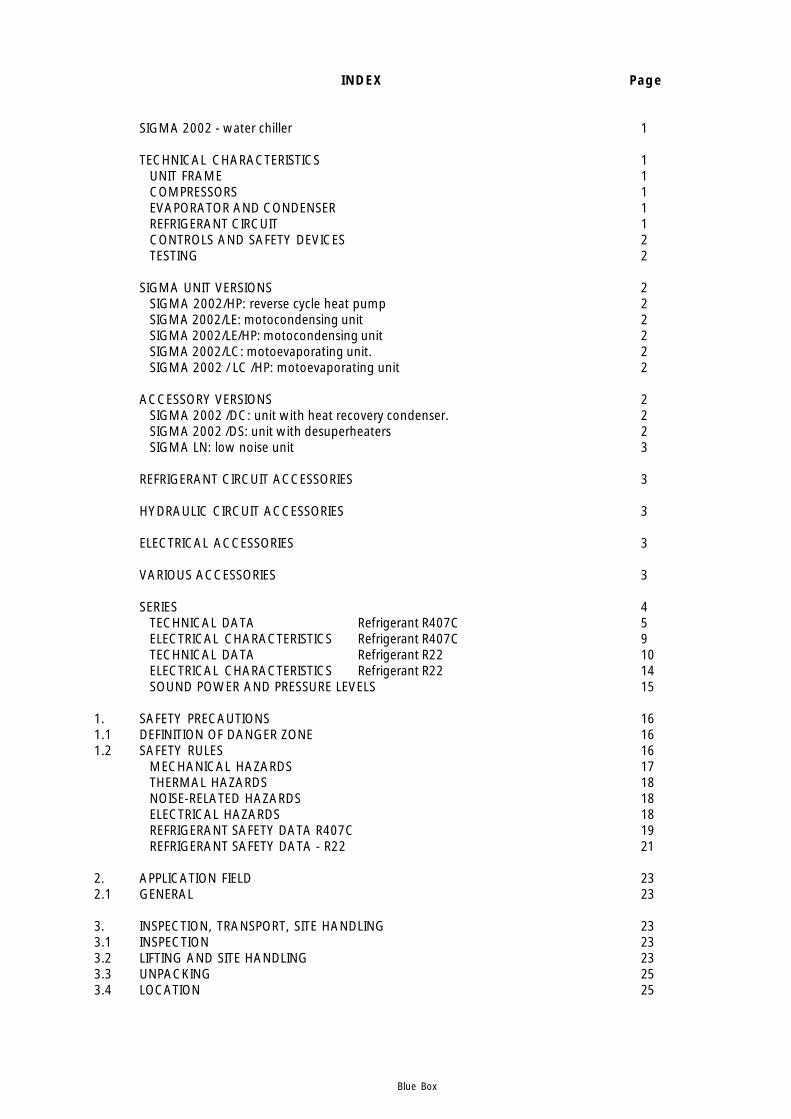
INDEX Page
SIGMA 2002 - water chiller 1
TECHNICAL CHARACTERISTICS 1UNIT FRAME 1COMPRESSORS 1EVAPORATOR AND CONDENSER 1REFRIGERANT CIRCUIT 1CONTROLS AND SAFETY DEVICES 2TESTING 2
SIGMA UNIT VERSIONS 2SIGMA 2002/HP: reverse cycle heat pump 2SIGMA 2002/LE: motocondensing unit 2SIGMA 2002/LE/HP: motocondensing unit 2SIGMA 2002/LC: motoevaporating unit. 2SIGMA 2002 / LC /HP: motoevaporating unit 2
ACCESSORY VERSIONS 2SIGMA 2002 /DC: unit with heat recovery condenser. 2SIGMA 2002 /DS: unit with desuperheaters 2SIGMA LN: low noise unit 3
REFRIGERANT CIRCUIT ACCESSORIES 3
HYDRAULIC CIRCUIT ACCESSORIES 3
ELECTRICAL ACCESSORIES 3
VARIOUS ACCESSORIES 3
SERIES 4TECHNICAL DATA Refrigerant R407C 5ELECTRICAL CHARACTERISTICS Refrigerant R407C 9TECHNICAL DATA Refrigerant R22 10ELECTRICAL CHARACTERISTICS Refrigerant R22 14SOUND POWER AND PRESSURE LEVELS 15
1. SAFETY PRECAUTIONS 161.1 DEFINITION OF DANGER ZONE 161.2 SAFETY RULES 16
MECHANICAL HAZARDS 17THERMAL HAZARDS 18NOISE-RELATED HAZARDS 18ELECTRICAL HAZARDS 18REFRIGERANT SAFETY DATA R407C 19REFRIGERANT SAFETY DATA - R22 21
2. APPLICATION FIELD 232.1 GENERAL 23
3. INSPECTION, TRANSPORT, SITE HANDLING 233.1 INSPECTION 233.2 LIFTING AND SITE HANDLING 233.3 UNPACKING 253.4 LOCATION 25
Blue Box
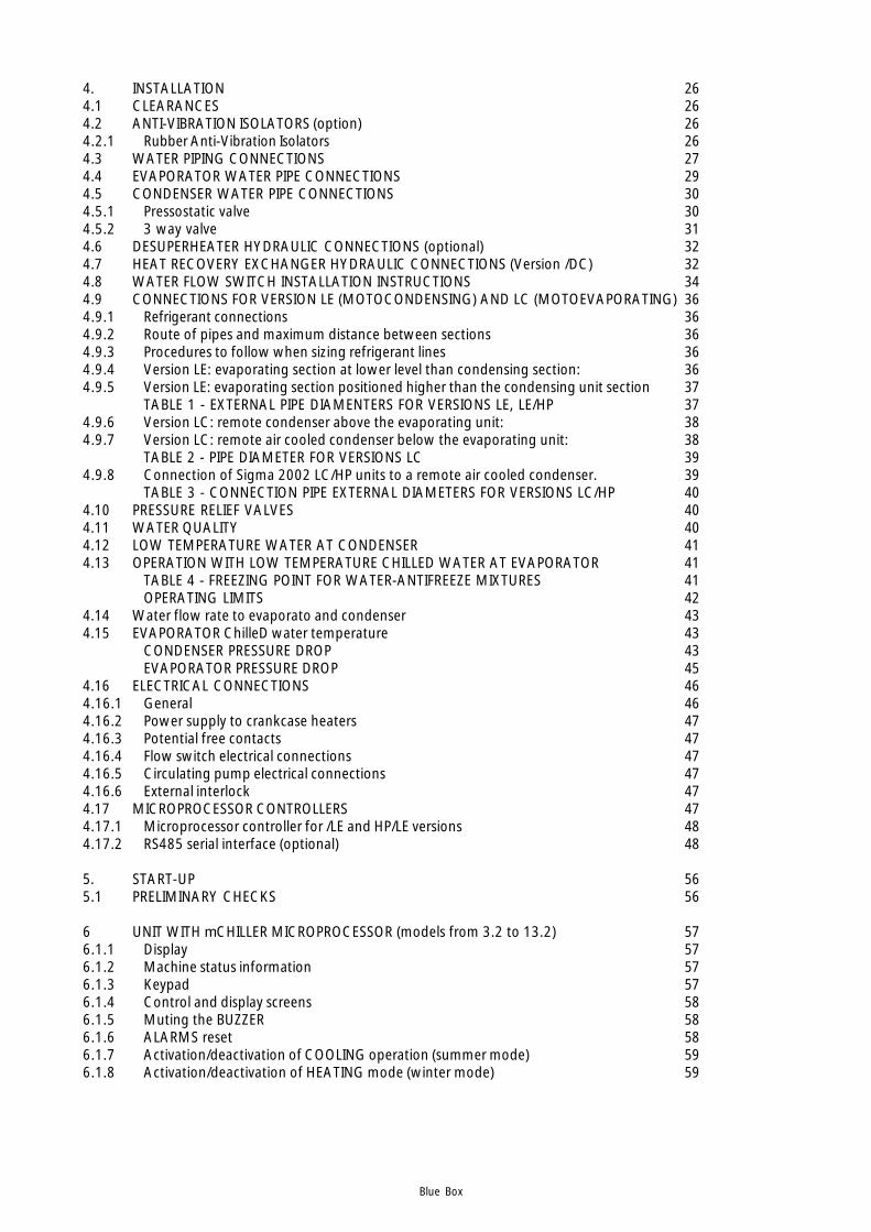
4. INSTALLATION 264.1 CLEARANCES 264.2 ANTI-VIBRATION ISOLATORS (option) 264.2.1 Rubber Anti-Vibration Isolators 264.3 WATER PIPING CONNECTIONS 274.4 EVAPORATOR WATER PIPE CONNECTIONS 294.5 CONDENSER WATER PIPE CONNECTIONS 304.5.1 Pressostatic valve 304.5.2 3 way valve 314.6 DESUPERHEATER HYDRAULIC CONNECTIONS (optional) 324.7 HEAT RECOVERY EXCHANGER HYDRAULIC CONNECTIONS (Version /DC) 324.8 WATER FLOW SWITCH INSTALLATION INSTRUCTIONS 344.9 CONNECTIONS FOR VERSION LE (MOTOCONDENSING) AND LC (MOTOEVAPORATING) 364.9.1 Refrigerant connections 364.9.2 Route of pipes and maximum distance between sections 364.9.3 Procedures to follow when sizing refrigerant lines 364.9.4 Version LE: evaporating section at lower level than condensing section: 364.9.5 Version LE: evaporating section positioned higher than the condensing unit section 37
TABLE 1 - EXTERNAL PIPE DIAMENTERS FOR VERSIONS LE, LE/HP 374.9.6 Version LC: remote condenser above the evaporating unit: 384.9.7 Version LC: remote air cooled condenser below the evaporating unit: 38
TABLE 2 - PIPE DIAMETER FOR VERSIONS LC 394.9.8 Connection of Sigma 2002 LC/HP units to a remote air cooled condenser. 39
TABLE 3 - CONNECTION PIPE EXTERNAL DIAMETERS FOR VERSIONS LC/HP 404.10 PRESSURE RELIEF VALVES 404.11 WATER QUALITY 404.12 LOW TEMPERATURE WATER AT CONDENSER 414.13 OPERATION WITH LOW TEMPERATURE CHILLED WATER AT EVAPORATOR 41
TABLE 4 - FREEZING POINT FOR WATER-ANTIFREEZE MIXTURES 41OPERATING LIMITS 42
4.14 Water flow rate to evaporato and condenser 434.15 EVAPORATOR ChilleD water temperature 43
CONDENSER PRESSURE DROP 43EVAPORATOR PRESSURE DROP 45
4.16 ELECTRICAL CONNECTIONS 464.16.1 General 464.16.2 Power supply to crankcase heaters 474.16.3 Potential free contacts 474.16.4 Flow switch electrical connections 474.16.5 Circulating pump electrical connections 474.16.6 External interlock 474.17 MICROPROCESSOR CONTROLLERS 474.17.1 Microprocessor controller for /LE and HP/LE versions 484.17.2 RS485 serial interface (optional) 48
5. START-UP 565.1 PRELIMINARY CHECKS 56
6 UNIT WITH mCHILLER MICROPROCESSOR (models from 3.2 to 13.2) 576.1.1 Display 576.1.2 Machine status information 576.1.3 Keypad 576.1.4 Control and display screens 586.1.5 Muting the BUZZER 586.1.6 ALARMS reset 586.1.7 Activation/deactivation of COOLING operation (summer mode) 596.1.8 Activation/deactivation of HEATING mode (winter mode) 59
Blue Box
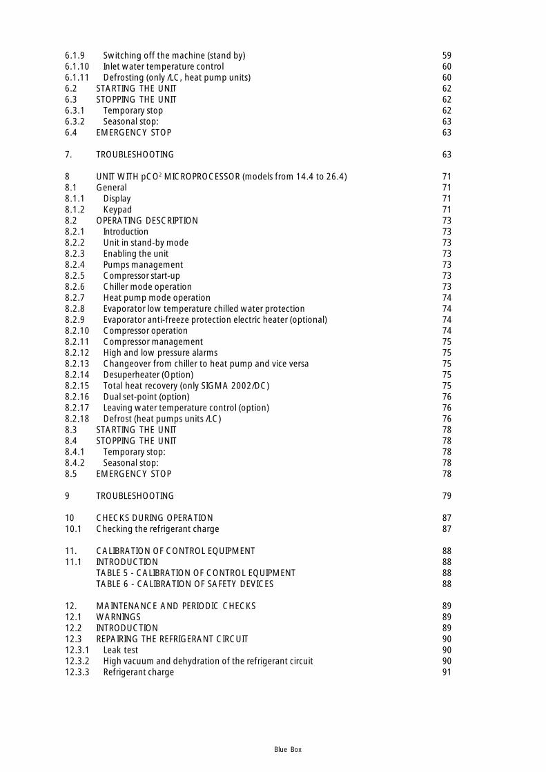
6.1.9 Switching off the machine (stand by) 596.1.10 Inlet water temperature control 606.1.11 Defrosting (only /LC, heat pump units) 606.2 STARTING THE UNIT 626.3 STOPPING THE UNIT 626.3.1 Temporary stop 626.3.2 Seasonal stop: 636.4 EMERGENCY STOP 63
7. TROUBLESHOOTING 63
8 UNIT WITH pCO2 MICROPROCESSOR (models from 14.4 to 26.4) 718.1 General 718.1.1 Display 718.1.2 Keypad 718.2 OPERATING DESCRIPTION 738.2.1 Introduction 738.2.2 Unit in stand-by mode 738.2.3 Enabling the unit 738.2.4 Pumps management 738.2.5 Compressor start-up 738.2.6 Chiller mode operation 738.2.7 Heat pump mode operation 748.2.8 Evaporator low temperature chilled water protection 748.2.9 Evaporator anti-freeze protection electric heater (optional) 748.2.10 Compressor operation 748.2.11 Compressor management 758.2.12 High and low pressure alarms 758.2.13 Changeover from chiller to heat pump and vice versa 758.2.14 Desuperheater (Option) 758.2.15 Total heat recovery (only SIGMA 2002/DC) 758.2.16 Dual set-point (option) 768.2.17 Leaving water temperature control (option) 768.2.18 Defrost (heat pumps units /LC) 768.3 STARTING THE UNIT 788.4 STOPPING THE UNIT 788.4.1 Temporary stop: 788.4.2 Seasonal stop: 788.5 EMERGENCY STOP 78
9 TROUBLESHOOTING 79
10 CHECKS DURING OPERATION 8710.1 Checking the refrigerant charge 87
11. CALIBRATION OF CONTROL EQUIPMENT 8811.1 INTRODUCTION 88
TABLE 5 - CALIBRATION OF CONTROL EQUIPMENT 88TABLE 6 - CALIBRATION OF SAFETY DEVICES 88
12. MAINTENANCE AND PERIODIC CHECKS 8912.1 WARNINGS 8912.2 INTRODUCTION 8912.3 REPAIRING THE REFRIGERANT CIRCUIT 9012.3.1 Leak test 9012.3.2 High vacuum and dehydration of the refrigerant circuit 9012.3.3 Refrigerant charge 91

Blue Box
12.4 ENVIRONMENTAL CONSIDERATIONS 91
13. DECOMMISSIONING THE UNIT 92
REFRIGERANT CIRCUIT DIAGRAM 93
DIMENSIONS, WEIGHTS AND HYDRAULIC CONNECTIONS 105

Blue Box - 1
SIGMA 2002 - water chiller
Water-cooled liquid chillers with hermetic scroll compressors and plate type evaporator, suitable for insideinstallations.
TECHNICAL CHARACTERISTICS
UNIT FRAMESelf supporting frame, constructed in galvanized sheet steel with RAL 7032 powder paint baked at 180°C toprovide a durable weatherproof finish.Models 3.2 to 7.2 and model 14.4 are completely enclosed by painted steel panels fully lined with a soundabsorbing material.On models 8.2 to 13.2 only the upper compartment, which contains the compressors, is fully enclosed on all sidesby painted steel panels fully lined with a sound absorbing material.On models 8.2 to 13.2 only the upper compartment , which contains the compressors, and the separator betweenthis compartment and the lower part of the unit are enclosed by painted steel panels fully lined with a soundabsorbing material.Models 16.4 to 26.4 do not have panels.
COMPRESSORSHermetic scroll type with orbital motion, connected in tandem and equipped with oil level sight glass, Klixoninternal thermal protection and oil equalisation line.
EVAPORATOR AND CONDENSERBrazed plate type in 316 AISI stainless steel. Thermal insulation of evaporator is provided by closed cell expandedmaterial. Each evaporator is equipped with a low water temperature probe for freeze protection and each unit isequipped as standard with a mechanical flow switch.
REFRIGERANT CIRCUITComprising: liquid valve, charge connection, liquid sight-glass, filter/dryer, thermostatic expansion valve withexternal pressure equalisation, high and low pressure switches for 2-compressor models.For 4-compressor models high and low pressure values and relative condensation and evaporation temperaturesare measured by pressure transducers that relay the signals to the controller so that they can be read directly onthe display. The high pressure side of the circuit is equipped with high pressure switches and relief valves.
ELECTRICAL PANELThe electrical panel includes:
- main switch- fuses for the auxiliary and power circuit- compressor contactors- microprocessor mCHILLER for 2 compressor units and PCO2 for 4 compressors units, controlling the following
functions:- water temperature regulation- freeze protection- compressor time intervals- compressor start sequence and automatic lead/lag selection- alarm reset- common alarm contact for remote signalling- operating and alarm indicator LEDs
- LCD display of the following information:- water inlet and outlet temperature- programmed temperature set-point and differential- alarms description- compressor hours run meter for units with PCO2 control- number of starts of the unit and the compressors- high and low pressure values and relative condensation and evaporation temperature values.
Electrical power supply [V/f/Hz]: 400/3~/50 ±5%
Blue Box - 2
SIGMA UNIT VERSIONS
SIGMA 2002/HP: reverse cycle heat pumpThe heat pump version operates as a water cooled chiller in summer and a water to water heat pump in winterby reversing the refrigerant flow to suit the required operating mode. In addition to the components of version SIGMA 2002, the heat pump version includes:REFRIGERANT CIRCUIT: 4-way reversing valve and a second thermostatic expansion valve.ELECTRICAL PANEL: Microprocessor programmed for summer/winter changeover (the Macroplus microprocessoris used on 4 compressor HP units).
SIGMA 2002/LE: motocondensing unitThe unit is designed to operate with a remotely located refrigerant to air evaporator. It is supplied without arefrigerant to water evaporator and thermostatic expansion valve. The solenoid valve on the liquid line is suppliedas standard. Models 3.2 to 13.2 have mchiller control and the remainder of the range is supplied without control.The standard supply is ON/OFF for each compressor from a digital entry.
SIGMA 2002/LE/HP: motocondensing unitThe unit is designed to operate with a remotely located refrigerant to air evaporator. It is supplied without arefrigerant to water evaporator and thermostatic expansion valve.The solenoid valve on the liquid line and liquid receivers are supplied as standard. Models 3.2 to 13.2 havemCHILLER control and the remainder of the range is supplied without control. The standard supply is ON/OFF foreach compressor from a digital entry.
SIGMA 2002/LC: motoevaporating unit.The unit is supplied without a water cooled condenser and is designed to be connected to a remotely located aircooled condenser.
SIGMA 2002 / LC /HP: motoevaporating unitThe unit is supplied without a water cooled condenser and is designed to be connected to a remotely located aircooled condenser.The solenoid valve on the liquid line and the liquid receivers are supplied as standard.
ACCESSORY VERSIONS
SIGMA 2002 /DC: unit with heat recovery condenser.Not available for HP versions.In addition to the components of version SIGMA 2002 this unit includes a 100% heat recovery condenser, for theproduction of hot water, and a liquid receiver on each refrigerant circuit.
SIGMA 2002 /DS: unit with desuperheatersAvailable for all models. A brazed plate type heat recovery exchanger (desuperheater) is arranged in series withthe condenser. Also available on all HP models. In this case an isolating valve must be fitted on the waterrecovery circuit and be closed during heat pump mode operation as described in the manual.
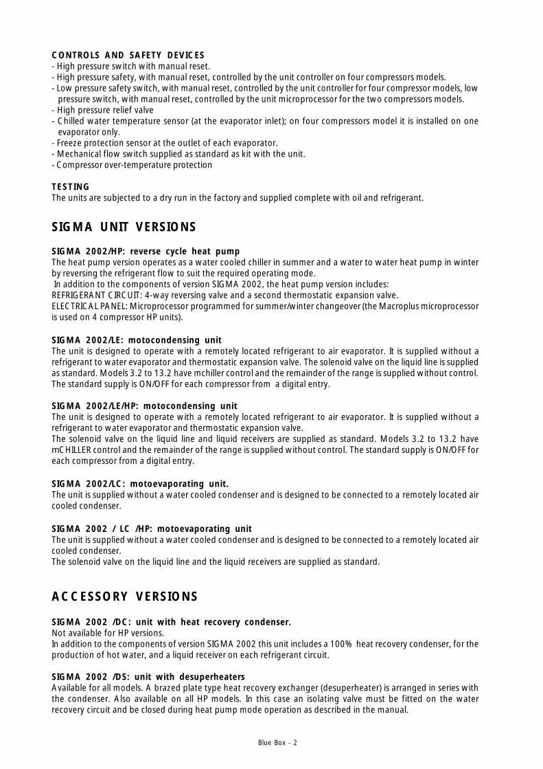
CONTROLS AND SAFETY DEVICES- High pressure switch with manual reset.- High pressure safety, with manual reset, controlled by the unit controller on four compressors models.- Low pressure safety switch, with manual reset, controlled by the unit controller for four compressor models, low
pressure switch, with manual reset, controlled by the unit microprocessor for the two compressors models.- High pressure relief valve- Chilled water temperature sensor (at the evaporator inlet); on four compressors model it is installed on one
evaporator only.- Freeze protection sensor at the outlet of each evaporator.- Mechanical flow switch supplied as standard as kit with the unit.- Compressor over-temperature protection
TESTINGThe units are subjected to a dry run in the factory and supplied complete with oil and refrigerant.
Blue Box - 3
VARIOUS ACCESSORIES
- Rubber antivibration mountings.- Timber crate packing- Pallet/skid for shipment in a container- Non-standard RAL paint colours- Unit completely pre-assembled, the unit will be supplied without refrigerant charge, test and PED certificate.- Modular pre-asembled unit, only 4 compressors models, with the exception of model 14.4.
REFRIGERANT CIRCUIT ACCESSORIES:
- Compressor suction and discharge valves Ball valve fitted in the equalisation line- Pressostatic valve (with solenoid valve on heat pump)- Liquid line solenoid valve- Pressure gauges. On all units with a PCO2 controller the suction and discharge pressures are displayed on the controller. Gauges
on standard units are located inside the compressor compartment.- Liquid receivers (standard on versions /LE/HP e LC/HP LC/DC e DC)- Dual set-point. With double thermostatic expansion valves and solenoid valves, the evaporator of “double set point units” is
sized on the basis of high temperature operation. On units with mCHILLER control, the set must be manually modified on the microprocessor control panel. On units with pCO2 control the two values can be set from the keypad or via a digital input. In all cases the
commutation between the two thermostatic expansion valves is automatic on the basis of the water tempera-ture. Thermostatic expansion valve selection is made according to the temperature values specified at the timeof order. The operating limits remain unchanged and are as per the catalogue. If glycol is used, in a sufficientpercentage to avoid freezing, the lower limit of the leaving water is extended to a minimum of -5 °C.
- Condenser for well water (only standard version and LE).
HYDRAULIC CIRCUIT ACCESSORIES
- Leaving water temperature control. Available only on units with control pCO2 (not HP versions).
- Water manifold (only 4 compressors models). Available for condensers, evaporators and heat recovery.
ELECTRICAL ACCESSORIES
- Power factor correction cos f fg0.9 at nominal operating conditions- Single voltage-free contacts for machine status signals- Serial interface. In units with a mCHILLER controller ( 3.2-13.2) the serial interface is the RS485 type with a Carel
protocol. In units with a PC02 control (from 14.4-26.4 excluding HP versions) the serial interface is the RS485type with a Modbus protocol. Special protocols can be ordered: Carel; Echelon in RS485 or FTT10 versions. HPunits can be supplied with a Macroplus microprocessor controller with a RS422 type serial interface; refer to themanual enclosed with the unit.
- Remote user terminal panel (in addition to the standard terminal) Not available on HP units (with a Macroplus controller)- Set point variable with remote signal (0-1V, 0-10V, 0-4mA, 0-20mA) available only on units with a PC02
controller, only in cooling mode. At the time of order. The set point values must be specified at the time oforder.
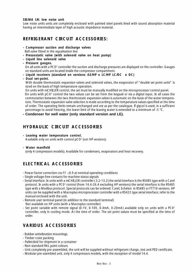
SIGMA LN: low noise unitLow noise units units are completely enclosed with painted steel panels lined with sound absorption materialhaving an intermediate layer of high acoustic impedance material.
Blue Box - 4
SERIES
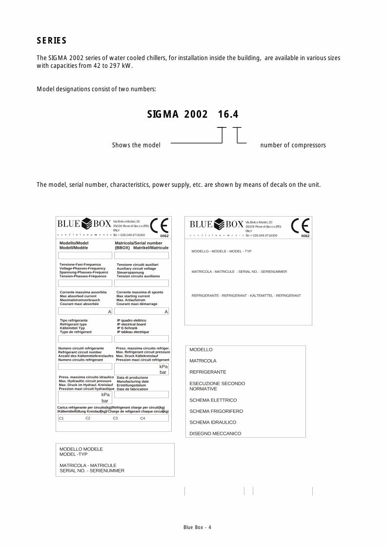
The SIGMA 2002 series of water cooled chillers, for installation inside the building, are available in various sizeswith capacities from 42 to 297 kW.
Model designations consist of two numbers:
SIGMA 2002 16.4
Shows the model number of compressors
The model, serial number, characteristics, power supply, etc. are shown by means of decals on the unit.
SERIAL NO. - SERIENUMMERMATRICOLA - MATRICULE
Corrente massima di spuntoMax starting currentMax. AnlaufstromCourant maxi démarrage
Tipo refrigeranteRefrigerant typeKältemittel TypType de refrigerant
Numero circuiti refrigeranteRefrigerant circuit numberAnzahl des KältemittelkreislaufesNumero circuits refrigerant
Press. massima circuito idraulicoMax. Hydraultic circuit pressureMax. Druck im Hydraul. KreislaufPression maxi circuit hydraulique
Data di produzioneManufacturing dateErstellungsdatumDate de fabrication
Press. massima circuito refriger.Max. Refrigerant circuit pressureMax. Druck KältekreislaufPression maxi circuit refrigerant
IP quadro elettricoIP electrical boardIP E-SchrankIP tableau electrique
Tensione circuiti ausiliariAuxiliary circuit voltageSteuerspannungTension circuits auxiliares
Matricola/Serial number(BBOX) Matrikel/Matricule
Corrente massima assorbitaMax absorbed currentMaximalstromverbrauchCourant maxi absorbée
Modello/ModelModell/Modèle
Tensione-Fasi-FrequenzaVoltage-Phasses-FrequencySpannung-Phasses-FrequenzTension-Phasses-Fréquence
Buono di Produzione
A A
kPa
MODELLO MODELEMODEL -TYP
kPa
Carica refrigerante per circuito(kg)/Refrigerant charge per circuitKältemittelfüllung Kreislauf Charge de refigerant chaque circuit
(kg)/ (kg)/ (kg)
C2C1 C3 C4
REFRIGERANTE - REFRIGERANT - KÄLTEMITTEL - REFRIGERANT
MATRICOLA - MATRICULE - SERIAL NO. - SERIENUMMER
MODELLO - MODELE - MODEL - TYP
REFRIGERANTE - REFRIGERANT - KÄLTEMITTEL - REFRIGERANT
MATRICOLA - MATRICULE - SERIAL NO. - SERIENUMMER
MODELLO - MODELE - MODEL - TYP
Buono di Produzione
bar
bar
0062 0062
0062
Via Enrico Mattei, 2035028 Piove di Sacco (PD)ITALYTel. +039.049.9716300
Via Enrico Mattei, 2035028 Piove di Sacco (PD)ITALYTel. +039.049.9716300
Via Enrico Mattei, 2035028 Piove di Sacco (PD)ITALYTel. +039.049.9716300
REFRIGERANTE
MATRICOLA
MODELLO
ESECUZIONE SECONDONORMATIVE
SCHEMA ELETTRICO
SCHEMA FRIGORIFERO
SCHEMA IDRAULICO
DISEGNO MECCANICO

Blue Box - 5
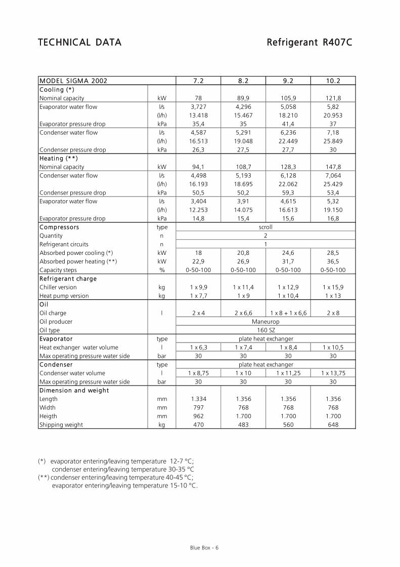
(*) evaporator entering/leaving temperature 12-7 °C; condenser entering/leaving temperature 30-35 °C(**) condenser entering/leaving temperature 40-45 °C; evaporator entering/leaving temperature 15-10 °C.
TECHNICAL DATATECHNICAL DATATECHNICAL DATATECHNICAL DATATECHNICAL DATA Refrigerant R407CRefrigerant R407CRefrigerant R407CRefrigerant R407CRefrigerant R407C
MODEL S IGMA 2002 3.2 4.2 5.2 6.2Cool ing (* )
Nominal capacity kW 42,4 51,2 59,8 68,9
Evaporator water flow l/s 2,025 2,445 2,857 3,292
(l/h) 7.290 8.800 10.285 11.851
Evaporator pressure drop kPa 49,9 45,5 39,6 36,2
Condenser water flow l/s 2,497 3,006 3,503 4,045
(l/h) 8.988 10.822 12.612 14.563
Condenser pressure drop kPa 37,9 37,9 39,4 27,1
Heating (**)
Nominal capacity kW 51,2 61,7 71,9 83
Condenser water flow l/s 2,447 2,949 3,435 3,967
(l/h) 8.809 10.616 12.367 14.280
Condenser pressure drop kPa 72,5 65,9 57 51,5
Evaporator water flow l/s 1,843 2,216 2,59 2,997
(l/h) 6.636 7.979 9.324 10.788
Evaporator pressure drop kPa 21,2 20,9 22 15,3
Compressors type
Quantity n
Refrigerant circuits n
Absorbed power cooling (*) kW 9,9 11,8 13,5 15,8
Absorbed power heating (**) kW 12,6 15,3 17,7 20,3
Capacity steps % 0-50-100 0-50-100 0-50-100 0-50-100
Refrigerant charge
Chiller version kg 1 x 3,8 1 x 4,8 1 x 5,9 1 x 8,5
Heat pump version kg 1 x 4,3 1 x 5,1 1 x 6,1 1 x 6,6
Oi l
Oil charge l 2 x 3,3 2 x 3,25 2 x 3,8 1 x 4 + 1 x 3,8
Oil producer
Oil type
Evaporator type
Heat exchanger water volume l 1 x 2,9 1 x 3,8 1 x 4,9 1 x 5,5
Max operating pressure water side bar 30 30 30 30
Condenser type
Condenser water volume l 1 x 3,1 1 x 3,9 1 x 4,7 1 x 7,5
Max operating pressure water side bar 30 30 30 30
Dimension and weight
Length mm 1.334 1.334 1.334 1.334
Width mm 797 797 797 797
Heigth mm 962 962 962 962
Shipping weight kg 379 403 414 447
scroll
2
Maneurop
160 SZ
plate heat exchanger
plate heat exchanger
1
Blue Box - 6
TECHNICAL DATATECHNICAL DATATECHNICAL DATATECHNICAL DATATECHNICAL DATA Refrigerant R407CRefrigerant R407CRefrigerant R407CRefrigerant R407CRefrigerant R407C
(*) evaporator entering/leaving temperature 12-7 °C; condenser entering/leaving temperature 30-35 °C(**) condenser entering/leaving temperature 40-45 °C; evaporator entering/leaving temperature 15-10 °C.
MODEL S IGMA 2002 7.2 8.2 9.2 10.2Cool ing (* )
Nominal capacity kW 78 89,9 105,9 121,8
Evaporator water flow l/s 3,727 4,296 5,058 5,82
(l/h) 13.418 15.467 18.210 20.953
Evaporator pressure drop kPa 35,4 35 41,4 37
Condenser water flow l/s 4,587 5,291 6,236 7,18
(l/h) 16.513 19.048 22.449 25.849
Condenser pressure drop kPa 26,3 27,5 27,7 30
Heating (**)
Nominal capacity kW 94,1 108,7 128,3 147,8
Condenser water flow l/s 4,498 5,193 6,128 7,064
(l/h) 16.193 18.695 22.062 25.429
Condenser pressure drop kPa 50,5 50,2 59,3 53,4
Evaporator water flow l/s 3,404 3,91 4,615 5,32
(l/h) 12.253 14.075 16.613 19.150
Evaporator pressure drop kPa 14,8 15,4 15,6 16,8
Compressors type
Quantity n
Refrigerant circuits n
Absorbed power cooling (*) kW 18 20,8 24,6 28,5
Absorbed power heating (**) kW 22,9 26,9 31,7 36,5
Capacity steps % 0-50-100 0-50-100 0-50-100 0-50-100
Refrigerant charge
Chiller version kg 1 x 9,9 1 x 11,4 1 x 12,9 1 x 15,9
Heat pump version kg 1 x 7,7 1 x 9 1 x 10,4 1 x 13
Oi l
Oil charge l 2 x 4 2 x 6,6 1 x 8 + 1 x 6,6 2 x 8
Oil producer
Oil type
Evaporator type
Heat exchanger water volume l 1 x 6,3 1 x 7,4 1 x 8,4 1 x 10,5
Max operating pressure water side bar 30 30 30 30
Condenser type
Condenser water volume l 1 x 8,75 1 x 10 1 x 11,25 1 x 13,75
Max operating pressure water side bar 30 30 30 30
Dimension and weight
Length mm 1.334 1.356 1.356 1.356
Width mm 797 768 768 768
Heigth mm 962 1.700 1.700 1.700
Shipping weight kg 470 483 560 648
scroll
2
1
plate heat exchanger
Maneurop
160 SZ
plate heat exchanger
Blue Box - 7
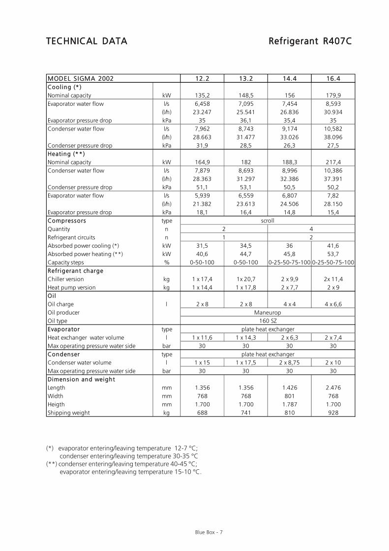
TECHNICAL DATATECHNICAL DATATECHNICAL DATATECHNICAL DATATECHNICAL DATA Refrigerant R407CRefrigerant R407CRefrigerant R407CRefrigerant R407CRefrigerant R407C
(*) evaporator entering/leaving temperature 12-7 °C; condenser entering/leaving temperature 30-35 °C(**) condenser entering/leaving temperature 40-45 °C; evaporator entering/leaving temperature 15-10 °C.
MODEL S IGMA 2002 12.2 13.2 14.4 16.4Cool ing (* )
Nominal capacity kW 135,2 148,5 156 179,9
Evaporator water flow l/s 6,458 7,095 7,454 8,593
(l/h) 23.247 25.541 26.836 30.934
Evaporator pressure drop kPa 35 36,1 35,4 35
Condenser water flow l/s 7,962 8,743 9,174 10,582
(l/h) 28.663 31.477 33.026 38.096
Condenser pressure drop kPa 31,9 28,5 26,3 27,5
Heating (**)
Nominal capacity kW 164,9 182 188,3 217,4
Condenser water flow l/s 7,879 8,693 8,996 10,386
(l/h) 28.363 31.297 32.386 37.391
Condenser pressure drop kPa 51,1 53,1 50,5 50,2
Evaporator water flow l/s 5,939 6,559 6,807 7,82
(l/h) 21.382 23.613 24.506 28.150
Evaporator pressure drop kPa 18,1 16,4 14,8 15,4
Compressors type
Quantity n
Refrigerant circuits n
Absorbed power cooling (*) kW 31,5 34,5 36 41,6
Absorbed power heating (**) kW 40,6 44,7 45,8 53,7
Capacity steps % 0-50-100 0-50-100 0-25-50-75-100 0-25-50-75-100
Refrigerant charge
Chiller version kg 1 x 17,4 1x 20,7 2 x 9,9 2x 11,4
Heat pump version kg 1 x 14,4 1 x 17,8 2 x 7,7 2 x 9
Oi l
Oil charge l 2 x 8 2 x 8 4 x 4 4 x 6,6
Oil producer
Oil type
Evaporator type
Heat exchanger water volume l 1 x 11,6 1 x 14,3 2 x 6,3 2 x 7,4
Max operating pressure water side bar 30 30 30 30
Condenser type
Condenser water volume l 1 x 15 1 x 17,5 2 x 8,75 2 x 10
Max operating pressure water side bar 30 30 30 30
Dimension and weight
Length mm 1.356 1.356 1.426 2.476
Width mm 768 768 801 768
Heigth mm 1.700 1.700 1.787 1.700
Shipping weight kg 688 741 810 928
2 4
Maneurop
160 SZ
plate heat exchanger
plate heat exchanger
1 2
scroll
Blue Box - 8
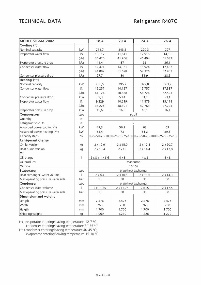
TECHNICAL DATATECHNICAL DATATECHNICAL DATATECHNICAL DATATECHNICAL DATA Refrigerant R407CRefrigerant R407CRefrigerant R407CRefrigerant R407CRefrigerant R407C
(*) evaporator entering/leaving temperature 12-7 °C; condenser entering/leaving temperature 30-35 °C(**) condenser entering/leaving temperature 40-45 °C; evaporator entering/leaving temperature 15-10 °C.
MODEL S IGMA 2002 18.4 20.4 24.4 26.4Cool ing (* )
Nominal capacity kW 211,7 243,6 270,3 297
Evaporator water flow l/s 10,117 11,641 12,915 14,19
(l/h) 36.420 41.906 46.494 51.083
Evaporator pressure drop kPa 41,4 37 35 36,1
Condenser water flow l/s 12,471 14,361 15,924 17,487
(l/h) 44.897 51.698 57.326 62.953
Condenser pressure drop kPa 27,7 30 31,9 28,5
Heating (**)
Nominal capacity kW 256,5 295,7 329,8 363,9
Condenser water flow l/s 12,257 14,127 15,757 17,387
(l/h) 44.124 50.858 56.726 62.593
Condenser pressure drop kPa 59,3 53,4 51,1 53,1
Evaporator water flow l/s 9,229 10,639 11,879 13,118
(l/h) 33.226 38.301 42.763 47.225
Evaporator pressure drop kPa 15,6 16,8 18,1 16,4
Compressors type
Quantity n
Refrigerant circuits n
Absorbed power cooling (*) kW 49,3 56,9 63 69
Absorbed power heating (**) kW 63,4 73 81,2 89,3
Capacity steps % 0-25-50-75-100 0-25-50-75-100 0-25-50-75-100 0-25-50-75-100
Refrigerant charge
Chiller version kg 2 x 12,9 2 x 15,9 2 x 17,4 2 x 20,7
Heat pump version kg 2 x 10,4 2 x 13 2 x 14,4 2 x 17,8
Oi l
Oil charge l 2 x 8 + 1 x 6,6 4 x 8 4 x 8 4 x 8
Oil producer
Oil type
Evaporator type
Heat exchanger water volume l 2 x 8,4 2 x 10,5 2 x 11,6 2 x 14,3
Max operating pressure water side bar 30 30 30 30
Condenser type
Condenser water volume l 2 x 11,25 2 x 13,75 2 x 15 2 x 17,5
Max operating pressure water side bar 30 30 30 30
Dimension and weight
Length mm 2.476 2.476 2.476 2.476
Width mm 768 768 768 768
Heigth mm 1.700 1.700 1.700 1.700
Shipping weight kg 1.069 1.210 1.226 1.270
plate heat exchanger
plate heat exchanger
Maneurop
160 SZ
scroll
2
4
Blue Box - 9
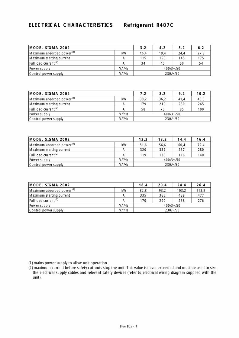
ELECTRICAL CHARACTERISTICS Refrigerant R407C
MODEL SIGMA 2002 3.2 4.2 5.2 6.2Maximum absorbed power (1) kW 16,4 19,4 24,4 27,3Maximum starting current A 115 150 145 175Full load current (2) A 34 40 50 54Power supply V/f/HzControl power supply V/f/Hz
400/3~/50230/~/50
MODEL SIGMA 2002 7.2 8.2 9.2 10.2Maximum absorbed power (1) kW 30,2 36,2 41,4 46,6Maximum starting current A 179 210 250 265Full load current (2) A 58 70 85 100Power supply V/f/HzControl power supply V/f/Hz
400/3~/50230/~/50
MODEL SIGMA 2002 12.2 13.2 14.4 16.4Maximum absorbed power (1) kW 51,6 56,6 60,4 72,4Maximum starting current A 320 339 237 280Full load current (2) A 119 138 116 140Power supply V/f/HzControl power supply V/f/Hz
400/3~/50230/~/50
MODEL SIGMA 2002 18.4 20.4 24.4 26.4Maximum absorbed power (1) kW 82,8 93,2 103,2 113,2Maximum starting current A 335 365 439 477Full load current (2) A 170 200 238 276Power supply V/f/HzControl power supply V/f/Hz
400/3~/50230/~/50
(1) mains power supply to allow unit operation.(2) maximum current before safety cut-outs stop the unit. This value is never exceeded and must be used to size
the electrical supply cables and relevant safety devices (refer to electrical wiring diagram supplied with theunit).
Blue Box - 10
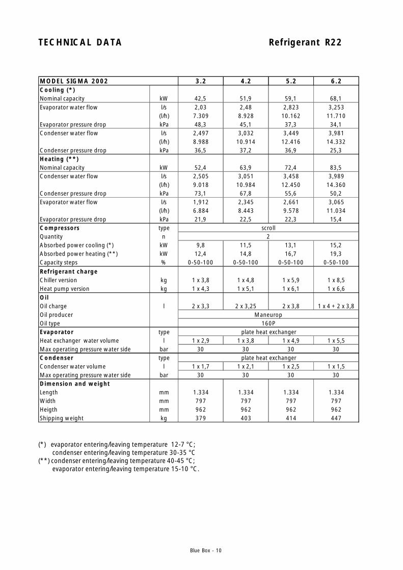
TECHNICAL DATA Refrigerant R22
MODEL SIGMA 2002 3.2 4.2 5.2 6.2Cool ing (*)Nominal capacity kW 42,5 51,9 59,1 68,1Evaporator water flow l/s 2,03 2,48 2,823 3,253
(l/h) 7.309 8.928 10.162 11.710Evaporator pressure drop kPa 48,3 45,1 37,3 34,1Condenser water flow l/s 2,497 3,032 3,449 3,981
(l/h) 8.988 10.914 12.416 14.332Condenser pressure drop kPa 36,5 37,2 36,9 25,3Heating (**)Nominal capacity kW 52,4 63,9 72,4 83,5Condenser water flow l/s 2,505 3,051 3,458 3,989
(l/h) 9.018 10.984 12.450 14.360Condenser pressure drop kPa 73,1 67,8 55,6 50,2Evaporator water flow l/s 1,912 2,345 2,661 3,065
(l/h) 6.884 8.443 9.578 11.034Evaporator pressure drop kPa 21,9 22,5 22,3 15,4Compressors typeQuantity nAbsorbed power cooling (*) kW 9,8 11,5 13,1 15,2Absorbed power heating (**) kW 12,4 14,8 16,7 19,3Capacity steps % 0-50-100 0-50-100 0-50-100 0-50-100Refr igerant chargeChiller version kg 1 x 3,8 1 x 4,8 1 x 5,9 1 x 8,5Heat pump version kg 1 x 4,3 1 x 5,1 1 x 6,1 1 x 6,6Oi lOil charge l 2 x 3,3 2 x 3,25 2 x 3,8 1 x 4 + 2 x 3,8Oil producerOil typeEvaporator typeHeat exchanger water volume l 1 x 2,9 1 x 3,8 1 x 4,9 1 x 5,5Max operating pressure water side bar 30 30 30 30Condenser typeCondenser water volume l 1 x 1,7 1 x 2,1 1 x 2,5 1 x 1,5Max operating pressure water side bar 30 30 30 30Dimension and weightLength mm 1.334 1.334 1.334 1.334Width mm 797 797 797 797Heigth mm 962 962 962 962Shipping weight kg 379 403 414 447
scroll
Maneurop160P
plate heat exchanger
plate heat exchanger
2
(*) evaporator entering/leaving temperature 12-7 °C; condenser entering/leaving temperature 30-35 °C(**) condenser entering/leaving temperature 40-45 °C; evaporator entering/leaving temperature 15-10 °C.
Blue Box - 11
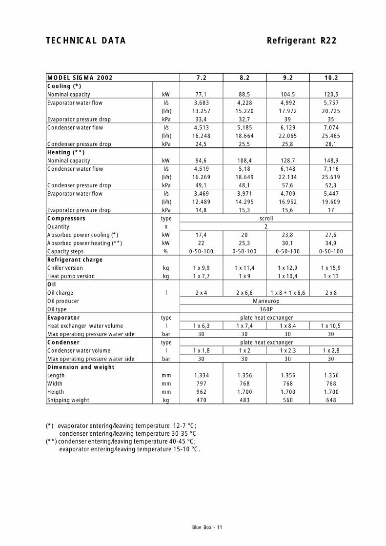
TECHNICAL DATA Refrigerant R22
MODEL SIGMA 2002 7.2 8.2 9.2 10.2Cool ing (*)Nominal capacity kW 77,1 88,5 104,5 120,5Evaporator water flow l/s 3,683 4,228 4,992 5,757
(l/h) 13.257 15.220 17.972 20.725Evaporator pressure drop kPa 33,4 32,7 39 35Condenser water flow l/s 4,513 5,185 6,129 7,074
(l/h) 16.248 18.664 22.065 25.465Condenser pressure drop kPa 24,5 25,5 25,8 28,1Heating (**)Nominal capacity kW 94,6 108,4 128,7 148,9Condenser water flow l/s 4,519 5,18 6,148 7,116
(l/h) 16.269 18.649 22.134 25.619Condenser pressure drop kPa 49,1 48,1 57,6 52,3Evaporator water flow l/s 3,469 3,971 4,709 5,447
(l/h) 12.489 14.295 16.952 19.609Evaporator pressure drop kPa 14,8 15,3 15,6 17Compressors typeQuantity nAbsorbed power cooling (*) kW 17,4 20 23,8 27,6Absorbed power heating (**) kW 22 25,3 30,1 34,9Capacity steps % 0-50-100 0-50-100 0-50-100 0-50-100Refr igerant chargeChiller version kg 1 x 9,9 1 x 11,4 1 x 12,9 1 x 15,9Heat pump version kg 1 x 7,7 1 x 9 1 x 10,4 1 x 13Oi lOil charge l 2 x 4 2 x 6,6 1 x 8 + 1 x 6,6 2 x 8Oil producerOil typeEvaporator typeHeat exchanger water volume l 1 x 6,3 1 x 7,4 1 x 8,4 1 x 10,5Max operating pressure water side bar 30 30 30 30Condenser typeCondenser water volume l 1 x 1,8 1 x 2 1 x 2,3 1 x 2,8Max operating pressure water side bar 30 30 30 30Dimension and weightLength mm 1.334 1.356 1.356 1.356Width mm 797 768 768 768Heigth mm 962 1.700 1.700 1.700Shipping weight kg 470 483 560 648
scroll2
Maneurop160P
plate heat exchanger
plate heat exchanger
(*) evaporator entering/leaving temperature 12-7 °C; condenser entering/leaving temperature 30-35 °C(**) condenser entering/leaving temperature 40-45 °C; evaporator entering/leaving temperature 15-10 °C.

Blue Box - 12
TECHNICAL DATA Refrigerant R22
MODEL SIGMA 2002 12.2 13.2 14.4 16.4Cool ing (*)Nominal capacity kW 133,7 146,9 154,2 177Evaporator water flow l/s 6,389 7,021 7,365 8,455
(l/h) 23.000 25.275 26.514 30.440Evaporator pressure drop kPa 33,1 34,1 33,4 32,7Condenser water flow l/s 7,848 8,623 9,026 10,369
(l/h) 28.255 31.044 32.495 37.329Condenser pressure drop kPa 29,9 26,7 24,5 25,5Heating (**)Nominal capacity kW 166,1 183,3 189,2 216,8Condenser water flow l/s 7,937 8,758 9,038 10,36
(l/h) 28.574 31.528 32.538 37.298Condenser pressure drop kPa 49,9 51,9 49,1 48,1Evaporator water flow l/s 6,081 6,716 6,939 7,942
(l/h) 21.893 24.177 24.979 28.590Evaporator pressure drop kPa 18,3 16,5 14,8 15,3Compressors typeQuantity nAbsorbed power cooling (*) kW 30,6 33,5 34,8 40,1Absorbed power heating (**) kW 38,8 42,7 43,9 50,6Capacity steps % 0-50-100 0-50-100 0-50-100 0-25-50-75-100Refr igerant chargeChiller version kg 1 x 17,4 1x 20,7 2 x 9,9 2x 11,4Heat pump version kg 1 x 14,4 1 x 17,8 2 x 7,7 2 x 9Oi lOil charge l 2 x 8 2 x 8 4 x 4 4 x 6,6Oil producerOil typeEvaporator typeHeat exchanger water volume l 1 x 11,6 1 x 14,3 2 x 6,3 2 x 7,4Max operating pressure water side bar 30 30 30 30Condenser typeCondenser water volume l 1 x 3 1 x 3,5 2 x 1,8 2 x 2Max operating pressure water side bar 30 30 30 30Dimension and weightLength mm 1.356 1.356 1.426 2.476Width mm 768 768 801 768Heigth mm 1.700 1.700 1.787 1.700Shipping weight kg 688 741 810 928
2 4scroll
Maneurop160P
plate heat exchanger
plate heat exchanger
(*) evaporator entering/leaving temperature 12-7 °C; condenser entering/leaving temperature 30-35 °C(**) condenser entering/leaving temperature 40-45 °C; evaporator entering/leaving temperature 15-10 °C.
Blue Box - 13
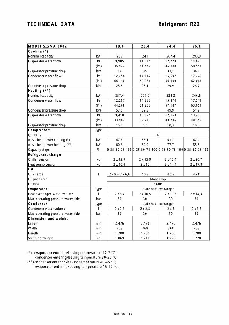
TECHNICAL DATA Refrigerant R22
MODEL SIGMA 2002 18.4 20.4 24.4 26.4Cool ing (*)Nominal capacity kW 209 241 267,4 293,9Evaporator water flow l/s 9,985 11,514 12,778 14,042
(l/h) 35.944 41.449 46.000 50.550Evaporator pressure drop kPa 39 35 33,1 34,1Condenser water flow l/s 12,258 14,147 15,697 17,247
(l/h) 44.130 50.931 56.509 62.088Condenser pressure drop kPa 25,8 28,1 29,9 26,7Heating (**)Nominal capacity kW 257,4 297,9 332,3 366,6Condenser water flow l/s 12,297 14,233 15,874 17,516
(l/h) 44.268 51.238 57.147 63.056Condenser pressure drop kPa 57,6 52,3 49,9 51,9Evaporator water flow l/s 9,418 10,894 12,163 13,432
(l/h) 33.904 39.218 43.786 48.354Evaporator pressure drop kPa 15,6 17 18,3 16,5Compressors typeQuantity nAbsorbed power cooling (*) kW 47,6 55,1 61,1 67,1Absorbed power heating (**) kW 60,3 69,9 77,7 85,5Capacity steps % 0-25-50-75-100 0-25-50-75-100 0-25-50-75-100 0-25-50-75-100Refr igerant chargeChiller version kg 2 x 12,9 2 x 15,9 2 x 17,4 2 x 20,7Heat pump version kg 2 x 10,4 2 x 13 2 x 14,4 2 x 17,8Oi lOil charge l 2 x 8 + 2 x 6,6 4 x 8 4 x 8 4 x 8Oil producerOil typeEvaporator typeHeat exchanger water volume l 2 x 8,4 2 x 10,5 2 x 11,6 2 x 14,3Max operating pressure water side bar 30 30 30 30Condenser typeCondenser water volume l 2 x 2,3 2 x 2,8 2 x 3 2 x 3,5Max operating pressure water side bar 30 30 30 30Dimension and weightLength mm 2.476 2.476 2.476 2.476Width mm 768 768 768 768Heigth mm 1.700 1.700 1.700 1.700Shipping weight kg 1.069 1.210 1.226 1.270
plate heat exchanger
plate heat exchanger
4
Maneurop160P
(*) evaporator entering/leaving temperature 12-7 °C; condenser entering/leaving temperature 30-35 °C(**) condenser entering/leaving temperature 40-45 °C; evaporator entering/leaving temperature 15-10 °C.
Blue Box - 14
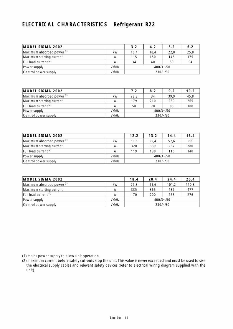
ELECTRICAL CHARACTERISTICS Refrigerant R22
MODEL SIGMA 2002 3.2 4.2 5.2 6.2Maximum absorbed power (1) kW 16,4 18,4 22,8 25,8Maximum starting current A 115 150 145 175Full load current (2) A 34 40 50 54Power supply V/f/HzControl power supply V/f/Hz
400/3~/50230/~/50
MODEL SIGMA 2002 7.2 8.2 9.2 10.2Maximum absorbed power (1) kW 28,8 34 39,9 45,8Maximum starting current A 179 210 250 265Full load current (2) A 58 70 85 100Power supply V/f/HzControl power supply V/f/Hz
400/3~/50230/~/50
MODEL SIGMA 2002 12.2 13.2 14.4 16.4Maximum absorbed power (1) kW 50,6 55,4 57,6 68Maximum starting current A 320 339 237 280Full load current (2) A 119 138 116 140Power supply V/f/HzControl power supply V/f/Hz
400/3~/50230/~/50
MODEL SIGMA 2002 18.4 20.4 24.4 26.4Maximum absorbed power (1) kW 79,8 91,6 101,2 110,8Maximum starting current A 335 365 439 477Full load current (2) A 170 200 238 276Power supply V/f/HzControl power supply V/f/Hz
400/3~/50230/~/50
(1) mains power supply to allow unit operation.(2) maximum current before safety cut-outs stop the unit. This value is never exceeded and must be used to size
the electrical supply cables and relevant safety devices (refer to electrical wiring diagram supplied with theunit).

Blue Box - 15
SOUND POWER AND PRESSURE LEVELS
STANDARD UNITS
LOW NOISE UNITS
SIGMA2002
Lw Lp Lw Lp Lw Lp Lw Lp Lw Lp Lw Lp Lw Lp Lw Lp Lw Lp
3.2 86,7 71,6 69,5 54,3 67,8 52,6 68,6 53,4 64,1 48,9 60,8 45,6 57,1 41,9 51,7 36,5 70,2 55,0
4.2 86,9 71,8 69,7 54,5 68,0 52,8 68,8 53,6 64,3 49,1 61,0 45,8 57,3 42,1 51,9 36,7 70,4 55,2
5.2 87,0 71,9 69,8 54,6 68,1 52,9 68,9 53,7 64,4 49,2 61,1 45,9 57,4 42,2 52,0 36,8 70,5 55,3
6.2 87,5 72,4 70,3 55,1 68,6 53,4 69,4 54,2 64,9 49,7 61,6 46,4 57,9 42,7 52,5 37,3 71,0 55,8
7.2 87,9 72,8 70,7 55,5 69,0 53,8 69,8 54,6 65,3 50,1 62,0 46,8 58,3 43,1 52,9 37,7 71,4 56,2
8.2 80,3 64,1 72,3 56,0 70,2 54,0 73,4 57,2 69,6 53,4 68,0 51,7 66,5 50,2 63,7 47,5 75,8 59,5
9.2 80,8 64,6 72,8 56,5 70,7 54,5 73,9 57,7 70,1 53,9 68,5 52,2 67,0 50,7 64,2 48,0 76,3 60,0
10.2 81,4 65,2 73,4 57,1 71,3 55,1 74,5 58,3 70,7 54,5 69,1 52,8 67,6 51,3 64,8 48,6 76,9 60,6
12.2 81,7 65,5 73,7 57,4 71,6 55,4 74,8 58,6 71,0 54,8 69,4 53,1 67,9 51,6 65,1 48,9 77,2 60,913.2 82,1 65,9 74,1 57,8 72,0 55,8 75,2 59,0 71,4 55,2 69,8 53,5 68,3 52,0 65,5 49,3 77,6 61,314.4 92,4 76,1 75,1 58,8 73,5 57,1 74,3 57,9 69,8 53,4 66,4 50,1 62,7 46,4 57,4 41,0 75,9 59,516.4 82,9 65,8 76,3 59,2 79,1 62,0 89,4 72,3 86,9 69,7 89,4 72,3 85,2 68,1 80,1 63,0 94,1 77,018.4 83,9 66,8 77,3 60,2 80,1 63,0 90,4 73,3 87,9 70,7 90,4 73,3 86,2 69,1 81,1 64,0 95,1 78,020.4 84,4 67,3 77,8 60,7 80,6 63,5 90,9 73,8 88,4 71,2 90,9 73,8 86,7 69,6 81,6 64,5 95,6 78,5
24.4 85,1 68,0 78,5 61,4 81,3 64,2 91,6 74,5 89,1 71,9 91,6 74,5 87,4 70,3 82,3 65,2 96,3 79,2
26.4 85,4 68,3 78,8 61,7 81,6 64,5 91,9 74,8 89,4 72,2 91,9 74,8 87,7 70,6 82,6 65,5 96,6 79,5
Octave band [Hz]
63
dB
125 250 500 1000 2000 4000 8000
dB dB dB dB dB dB dB
Total
dB(A)
SIGMA2002/LN Lw Lp Lw Lp Lw Lp Lw Lp Lw Lp Lw Lp Lw Lp Lw Lp Lw Lp
3.2 85,8 70,7 75,5 60,3 67,9 52,7 65,8 50,6 62,1 46,9 58,7 43,5 55,2 40,0 50,2 35,0 68,8 53,6
4.2 86,0 70,9 75,7 60,5 68,1 52,9 66,0 50,8 62,3 47,1 58,9 43,7 55,4 40,2 50,4 35,2 69,0 53,8
5.2 85,9 70,8 75,6 60,4 68,0 52,8 65,9 50,7 62,2 47,0 58,8 43,6 55,3 40,1 50,3 35,1 68,9 53,7
6.2 86,5 71,4 76,2 61,0 68,6 53,4 66,5 51,3 62,8 47,6 59,4 44,2 55,9 40,7 50,9 35,7 69,5 54,3
7.2 86,9 71,8 76,6 61,4 69,0 53,8 66,9 51,7 63,2 48,0 59,8 44,6 56,3 41,1 51,3 36,1 69,9 54,7
8.2 84,0 67,8 74,8 58,5 69,5 53,3 71,6 55,3 66,2 49,9 63,2 47,0 57,8 41,5 50,5 34,3 72,4 56,1
9.2 84,1 67,9 74,9 58,6 69,6 53,4 71,7 55,4 66,3 50,0 63,3 47,1 57,9 41,6 50,6 34,4 72,5 56,2
10.2 84,2 68,0 75,0 58,7 69,7 53,5 71,8 55,5 66,4 50,1 63,4 47,2 58,0 41,7 50,7 34,5 72,6 56,3
12.2 84,5 68,3 75,3 59,0 70,0 53,8 72,1 55,8 66,7 50,4 63,7 47,5 58,3 42,0 51,0 34,8 72,9 56,613.2 84,9 68,7 75,7 59,4 70,4 54,2 72,5 56,2 67,1 50,8 64,1 47,9 58,7 42,4 51,4 35,2 73,3 57,014.4 90,7 74,4 80,4 64,0 72,8 56,4 70,7 54,3 67,0 50,6 63,5 47,2 60,1 43,7 55,1 38,7 73,7 57,316.4 88,3 71,2 79,1 61,9 73,8 56,7 75,8 58,7 70,4 53,3 67,5 50,4 62,1 44,9 54,8 37,7 76,6 59,518.4 89,8 72,7 80,6 63,4 75,3 58,2 77,3 60,2 71,9 54,8 69,0 51,9 63,6 46,4 56,3 39,2 78,1 61,020.4 90,6 73,5 81,4 64,2 76,1 59,0 78,1 61,0 72,7 55,6 69,8 52,7 64,4 47,2 57,1 40,0 78,9 61,8
24.4 90,9 73,8 81,7 64,5 76,4 59,3 78,4 61,3 73,0 55,9 70,1 53,0 64,7 47,5 57,4 40,3 79,2 62,1
26.4 91,3 74,2 82,1 64,9 76,8 59,7 78,8 61,7 73,4 56,3 70,5 53,4 65,1 47,9 57,8 40,7 79,6 62,5
Octave band [Hz]
63 125 250 500 1000 2000 4000 8000 Total
dB dB dB dB dB dB dB dB dB(A)
Lw: sound power values in free field conditions are calculated in accordance with ISO 3746.Lp : sound pressure values measured at 1 m from the unit in free field conditions in compliance with ISO 3746
Blue Box - 16
1. SAFETY PRECAUTIONS
1.1 DEFINITION OF DANGER ZONE
Only authorised operators must be allowed in the vicinity of the unit.
- The external danger zone concerns a space of approximately 2 m in width around the perimeter of the machine.Access to this area must be prevented by suitable guarding in the event that the unit is located in an unprotectedarea that is easily accessible to unauthorised persons.
1.2 SAFETY RULES
The unit is designed and built in accordance with the PED 97/23CE rules, to ensure the maximum level of safety.To avoid possible situations of risk adhere to the following rules at all times:
- All work on the unit must be performed by qualified personnel. Before working on the unit, ensure that thedesignated personnel are conversant with the documentation supplied. Always ensure there is a copy of thedocumentation in the immediate vicinity of the unit.
- Use the appropriate personal safety equipment (gloves, helmet, safety goggles, safety footwear, etc.) for allmaintenance and control operations on the unit.
- Use only tools and equipment that are in good working order.
- The compressor compartment contains various high temperature components. Adopt the maximum cautionwhen working in the vicinity of the compressors and avoid touching any parts of the unit without appropriateprotection.
- Pipe the discharge of the relief valves.
- Do not work within the theoretical discharge trajectory of the relief valves.
Blue Box - 17
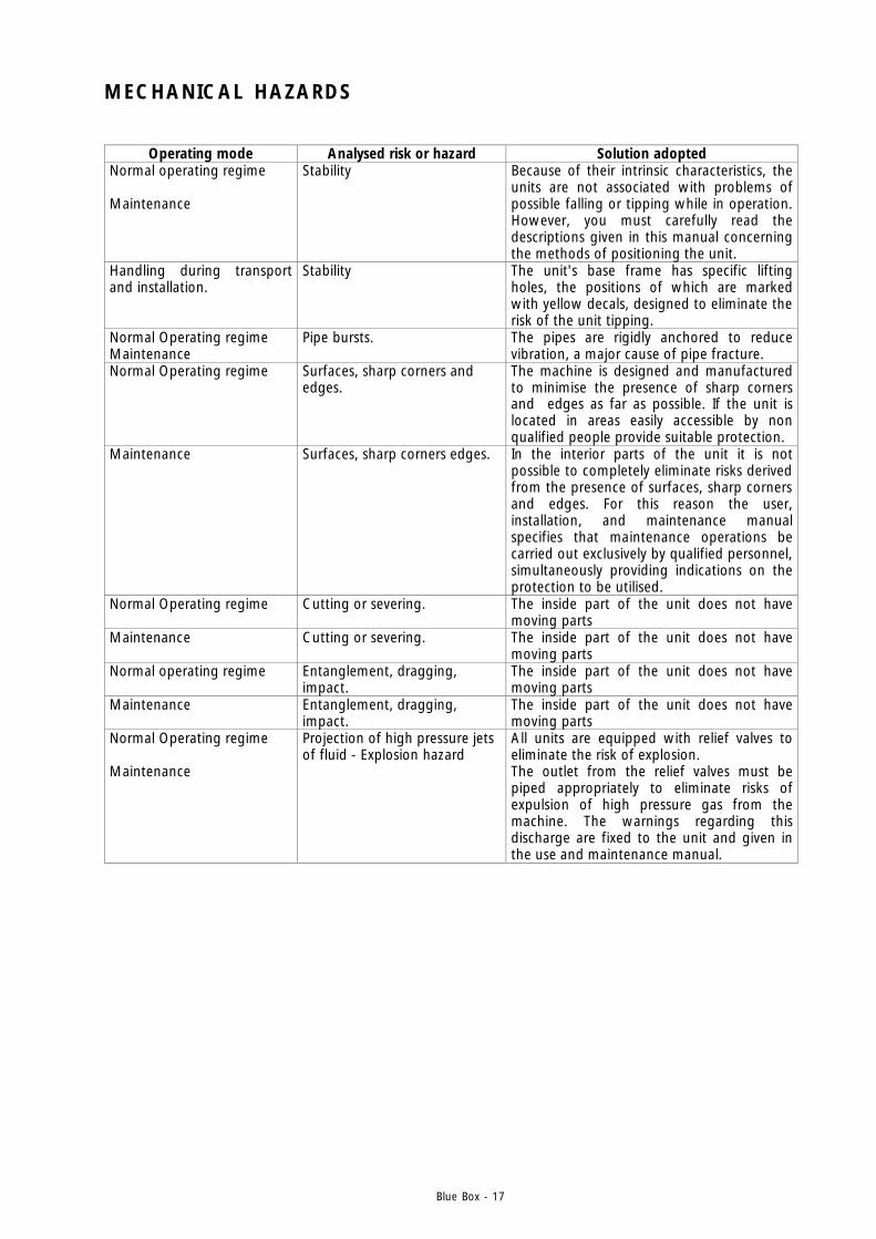
MECHANICAL HAZARDS
Operating mode Analysed risk or hazard Solution adopted Normal operating regime Maintenance
Stability Because of their intrinsic characteristics, the units are not associated with problems of possible falling or tipping while in operation. However, you must carefully read the descriptions given in this manual concerning the methods of positioning the unit.
Handling during transport and installation.
Stability The unit's base frame has specific lifting holes, the positions of which are marked with yellow decals, designed to eliminate the risk of the unit tipping.
Normal Operating regime Maintenance
Pipe bursts. The pipes are rigidly anchored to reduce vibration, a major cause of pipe fracture.
Normal Operating regime
Surfaces, sharp corners and edges.
The machine is designed and manufactured to minimise the presence of sharp corners and edges as far as possible. If the unit is located in areas easily accessible by non qualified people provide suitable protection.
Maintenance Surfaces, sharp corners edges. In the interior parts of the unit it is not possible to completely eliminate risks derived from the presence of surfaces, sharp corners and edges. For this reason the user, installation, and maintenance manual specifies that maintenance operations be carried out exclusively by qualified personnel, simultaneously providing indications on the protection to be utilised.
Normal Operating regime
Cutting or severing. The inside part of the unit does not have moving parts
Maintenance Cutting or severing. The inside part of the unit does not have moving parts
Normal operating regime
Entanglement, dragging, impact.
The inside part of the unit does not have moving parts
Maintenance Entanglement, dragging, impact.
The inside part of the unit does not have moving parts
Normal Operating regime Maintenance
Projection of high pressure jets of fluid - Explosion hazard
All units are equipped with relief valves to eliminate the risk of explosion. The outlet from the relief valves must be piped appropriately to eliminate risks of expulsion of high pressure gas from the machine. The warnings regarding this discharge are fixed to the unit and given in the use and maintenance manual.
Blue Box - 18
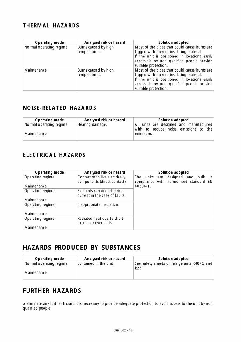
NOISE-RELATED HAZARDS
ELECTRICAL HAZARDS
THERMAL HAZARDS
HAZARDS PRODUCED BY SUBSTANCES
FURTHER HAZARDS
Operating mode Analysed risk or hazard Solution adopted Normal operating regime
Burns caused by high temperatures.
Most of the pipes that could cause burns are lagged with thermo insulating material. If the unit is positioned in locations easily accessible by non qualified people provide suitable protection.
Maintenance
Burns caused by high temperatures.
Most of the pipes that could cause burns are lagged with thermo insulating material. If the unit is positioned in locations easily accessible by non qualified people provide suitable protection.
Operating mode Analysed risk or hazard Solution adopted Operating regime Maintenance
Contact with live electrically components (direct contact).
Operating regime Maintenance
Elements carrying electrical current in the case of faults.
Operating regime Maintenance
Inappropriate insulation.
Operating regime Maintenance
Radiated heat due to short-circuits or overloads.
The units are designed and built in compliance with harmonised standard EN 60204-1.
Operating mode Analysed risk or hazard Solution adopted Normal operating regime Maintenance
contained in the unit See safety sheets of refrigerants R407C and R22
o eliminate any further hazard it is necessary to provide adequate protection to avoid access to the unit by non qualified people.
Operating mode Analysed risk or hazard Solution adopted Normal operating regime Maintenance
Hearing damage. All units are designed and manufactured with to reduce noise emissions to the minimum.
Blue Box - 19
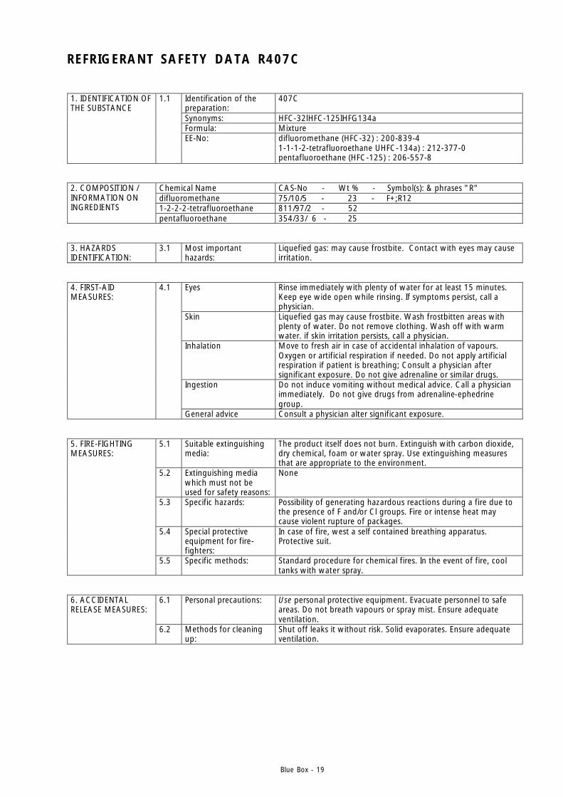
REFRIGERANT SAFETY DATA R407C
Identification of the preparation:
407C
Synonyms: HFC-32lHFC-125IHFG134a Formula: Mixture
1. IDENTIFICATION OF THE SUBSTANCE
1.1
EE-No: difluoromethane (HFC-32) : 200-839-4 1-1-1-2-tetrafluoroethane UHFC-134a) : 212-377-0 pentafluoroethane (HFC-125) : 206-557-8
Chemical Name CAS-No - Wt % - Symbol(s): & phrases "R" difluoromethane 75/10/5 - 23 - F+;R12 1-2-2-2-tetrafluoroethane 811/97/2 - 52
2. COMPOSITION / INFORMATION ON INGREDIENTS
pentafluoroethane 354/33/ 6 - 25 3. HAZARDS IDENTIFICATION:
3.1 Most important hazards:
Liquefied gas: may cause frostbite. Contact with eyes may cause irritation.
Eyes Rinse immediately with plenty of water for at least 15 minutes. Keep eye wide open while rinsing. If symptoms persist, call a physician.
Skin Liquefied gas may cause frostbite. Wash frostbitten areas with plenty of water. Do not remove clothing. Wash off with warm water. if skin irritation persists, call a physician.
Inhalation Move to fresh air in case of accidental inhalation of vapours. Oxygen or artificial respiration if needed. Do not apply artificial respiration if patient is breathing; Consult a physician after significant exposure. Do not give adrenaline or similar drugs.
Ingestion Do not induce vomiting without medical advice. Call a physician immediately. Do not give drugs from adrenaline-ephedrine group.
4. FIRST-AID MEASURES:
4.1
General advice Consult a physician alter significant exposure.
5.1 Suitable extinguishing media:
The product itself does not burn. Extinguish with carbon dioxide, dry chemical, foam or water spray. Use extinguishing measures that are appropriate to the environment.
5.2 Extinguishing media which must not be used for safety reasons:
None
5.3 Specific hazards: Possibility of generating hazardous reactions during a fire due to the presence of F and/or Cl groups. Fire or intense heat may cause violent rupture of packages.
5.4 Special protective equipment for fire-fighters:
In case of fire, west a self contained breathing apparatus. Protective suit.
5. FIRE-FIGHTING MEASURES:
5.5 Specific methods: Standard procedure for chemical fires. In the event of fire, cool tanks with water spray.
6.1 Personal precautions: Use personal protective equipment. Evacuate personnel to safe areas. Do not breath vapours or spray mist. Ensure adequate ventilation.
6. ACCIDENTAL RELEASE MEASURES:
6.2 Methods for cleaning up:
Shut off leaks it without risk. Solid evaporates. Ensure adequate ventilation.
Blue Box - 20
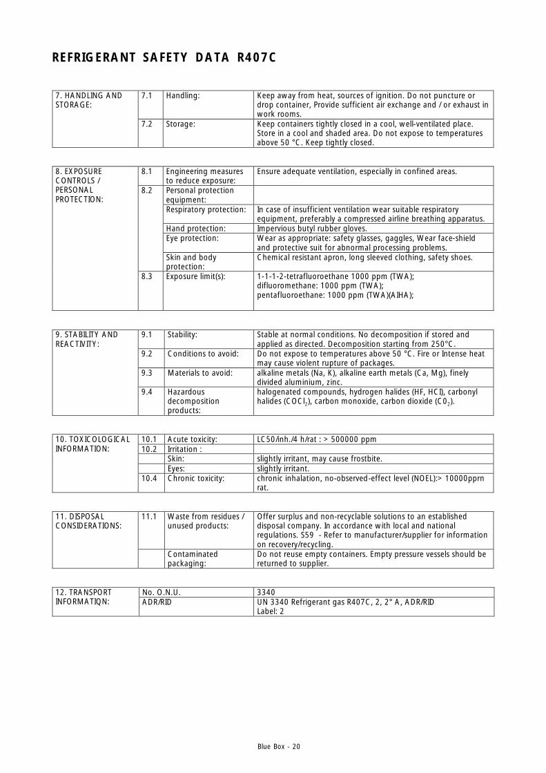
REFRIGERANT SAFETY DATA R407C
7.1 Handling: Keep away from heat, sources of ignition. Do not puncture or drop container, Provide sufficient air exchange and / or exhaust in work rooms.
7. HANDLING AND STORAGE:
7.2 Storage: Keep containers tightly closed in a cool, well-ventilated place. Store in a cool and shaded area. Do not expose to temperatures above 50 °C. Keep tightly closed.
8.1
Engineering measures to reduce exposure:
Ensure adequate ventilation, especially in confined areas.
Personal protection equipment:
Respiratory protection: In case of insufficient ventilation wear suitable respiratory equipment, preferably a compressed airline breathing apparatus.
Hand protection: Impervious butyl rubber gloves. Eye protection: Wear as appropriate: safety glasses, gaggles, Wear face-shield
and protective suit for abnormal processing problems.
8.2
Skin and body protection:
Chemical resistant apron, long sleeved clothing, safety shoes.
8. EXPOSURE CONTROLS / PERSONAL PROTECTION:
8.3
Exposure limit(s): 1-1-1-2-tetrafluoroethane 1000 ppm (TWA); difluoromethane: 1000 ppm (TWA); pentafluoroethane: 1000 ppm (TWA)(AIHA);
9.1 Stability: Stable at normal conditions. No decomposition if stored and applied as directed. Decomposition starting from 250°C.
9.2 Conditions to avoid: Do not expose to temperatures above 50 °C. Fire or Intense heat may cause violent rupture of packages.
9.3 Materials to avoid: alkaline metals (Na, K), alkaline earth metals (Ca, Mg), finely divided aluminium, zinc.
9. STABILITY AND REACTIVITY:
9.4
Hazardous decomposition products:
halogenated compounds, hydrogen halides (HF, HCI), carbonyl halides (COCl2), carbon monoxide, carbon dioxide (C02).
10.1 Acute toxicity: LC50/inh./4 h/rat : > 500000 ppm 10.2 Irritation : Skin: slightly irritant, may cause frostbite. Eyes: slightly irritant.
10. TOXICOLOGICAL INFORMATION:
10.4 Chronic toxicity: chronic inhalation, no-observed-effect level (NOEL):> 10000pprn rat.
11.1 Waste from residues / unused products:
Offer surplus and non-recyclable solutions to an established disposal company. In accordance with local and national regulations. S59 - Refer to manufacturer/supplier for information on recovery/recycling.
11. DISPOSAL CONSIDERATIONS:
Contaminated packaging:
Do not reuse empty containers. Empty pressure vessels should be returned to supplier.
No. O.N.U. 3340 12. TRANSPORT INFORMATIQN: ADR/RID UN 3340 Refrigerant gas R407C, 2, 2° A, ADR/RID
Label: 2

Blue Box - 21
REFRIGERANT SAFETY DATA - R22
Identification of the preparation:
HCFC-22
Synonyms: chlorodifluoromethane Formula: CHClF2 CAS-No 75-45-6
1. IDENTIFICATION OF THE SUBSTANCE
1.1
EEC-No 200-871-9
Chemical Name CAS-No - Wt % - Symbol(s): & phrases "R" 2. COMPOSITION / INGREDIENTS Chlorodifluoromethane 75/45/6 - 100 - R59 3. HAZARDS 3.1 Major hazards: Causes damage to ozone layer.
Eyes Rinse immediately with plenty of water for at least 15 minutes. Keep eyes wide open while rinsing. If symptoms persist, call a physician.
Skin Liquefied gas may cause frostbite. Wash frostbitten areas with plenty of water. Do not remove clothing. Wash off with warm water. if skin irritation persists, call a physician.
Inhalation Move to fresh air in case of accidental inhalation of vapours. Use oxygen or artificial respiration if needed. Do not apply artificial respiration if patient is breathing; Consult a physician after significant exposure. Do not give adrenaline or similar drugs.
Ingestion Do not induce vomiting without medical advice. Call a physician immediately. Do not give drugs from adrenaline-ephedrine group.
4. FIRST-AID MEASURES:
4.1
General advice Consult a physician alter significant exposure.
5.1 Suitable extinguishing media:
The product itself does not burn. Extinguish with carbon dioxide, dry chemical, foam or water spray. Use extinguishing measures that are appropriate to the environment.
5.2 Extinguishing media which must not be used for safety reasons:
None
5.3 Specific hazards: Possibility of generating hazardous reactions during a fire due to the presence of F and/or Cl groups. Fire or intense heat may cause violent rupture of containers.
5.4 Special protective equipment for fire-fighters:
In case of fire, wear a self contained breathing apparatus. Protective suit.
5. FIRE-FIGHTING MEASURES:
5.5 Specific methods: Standard procedure for chemical fires. In the event of fire, cool tanks with water spray.
6.1 Personal precautions: Use personal protective equipment. Evacuate personnel to safe areas. Do not breath vapours or spray mist. Ensure adequate ventilation.
6. ACCIDENTAL RELEASE MEASURES:
6.2 Methods for cleaning up:
Shut off leaks if without risk. Solid evaporates. Ensure adequate ventilation.
Blue Box - 22
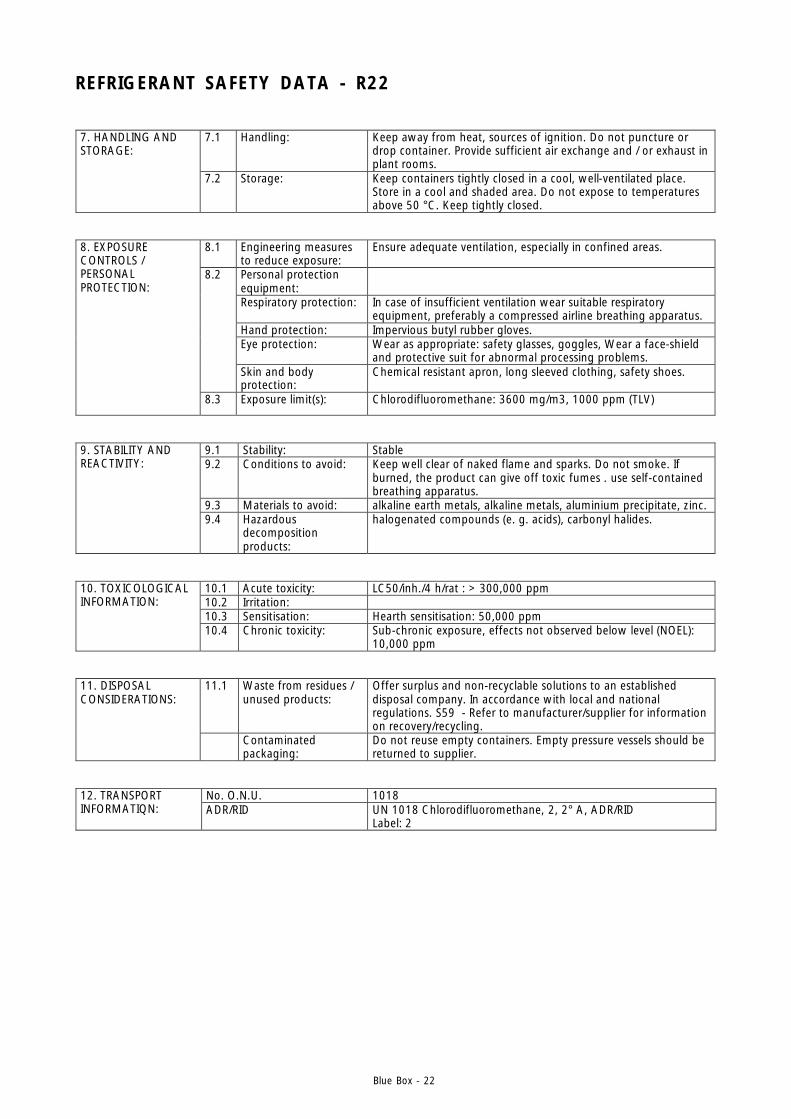
REFRIGERANT SAFETY DATA - R22
7.1 Handling: Keep away from heat, sources of ignition. Do not puncture or drop container. Provide sufficient air exchange and / or exhaust in plant rooms.
7. HANDLING AND STORAGE:
7.2 Storage: Keep containers tightly closed in a cool, well-ventilated place. Store in a cool and shaded area. Do not expose to temperatures above 50 °C. Keep tightly closed.
8.1
Engineering measures to reduce exposure:
Ensure adequate ventilation, especially in confined areas.
Personal protection equipment:
Respiratory protection: In case of insufficient ventilation wear suitable respiratory equipment, preferably a compressed airline breathing apparatus.
Hand protection: Impervious butyl rubber gloves. Eye protection: Wear as appropriate: safety glasses, goggles, Wear a face-shield
and protective suit for abnormal processing problems.
8.2
Skin and body protection:
Chemical resistant apron, long sleeved clothing, safety shoes.
8. EXPOSURE CONTROLS / PERSONAL PROTECTION:
8.3 Exposure limit(s): Chlorodifluoromethane: 3600 mg/m3, 1000 ppm (TLV)
9.1 Stability: Stable 9.2 Conditions to avoid: Keep well clear of naked flame and sparks. Do not smoke. If
burned, the product can give off toxic fumes . use self-contained breathing apparatus.
9.3 Materials to avoid: alkaline earth metals, alkaline metals, aluminium precipitate, zinc.
9. STABILITY AND REACTIVITY:
9.4
Hazardous decomposition products:
halogenated compounds (e. g. acids), carbonyl halides.
10.1 Acute toxicity: LC50/inh./4 h/rat : > 300,000 ppm 10.2 Irritation: 10.3 Sensitisation: Hearth sensitisation: 50,000 ppm
10. TOXICOLOGICAL INFORMATION:
10.4 Chronic toxicity: Sub-chronic exposure, effects not observed below level (NOEL): 10,000 ppm
11.1 Waste from residues / unused products:
Offer surplus and non-recyclable solutions to an established disposal company. In accordance with local and national regulations. S59 - Refer to manufacturer/supplier for information on recovery/recycling.
11. DISPOSAL CONSIDERATIONS:
Contaminated packaging:
Do not reuse empty containers. Empty pressure vessels should be returned to supplier.
No. O.N.U. 1018 12. TRANSPORT INFORMATIQN: ADR/RID UN 1018 Chlorodifluoromethane, 2, 2° A, ADR/RID
Label: 2
Blue Box - 23
Attention: before repairing or servicing the unit, ensure that the electricalsupply is disconnected.
Any work on the unit must be carried out by trained people only.
2. APPLICATION FIELD
SIGMA 2002 units have been designed for cooling water or water-glycol and are generally used in air conditioningor refrigeration applications.See chapter 6 for recommended operating ranges.
2.1 GENERAL
- When installing or servicing the unit, it is necessary to strictly follow the rules described in this manual, toconform to all the items detailed on the unit labels and take any necessary precaution.
- Pressure in refrigerant circuits and danger from electrical shock can be hazardous when installing or servicing theunit.
3. INSPECTION, TRANSPORT, SITE HANDLING
3.1 INSPECTION
After receiving the unit, immediately check its integrity. The unit will have left the factory in perfect condition.Therefore on receiving the unit any damage must be verbally described to the carrier and recorded on theDelivery Note before it is signed by both parties. Blue Box or their Agent must be informed as soon as possible ofthe extent of the damage.The Customer should prepare a written statement and photographic evidence regarding any severe damage.
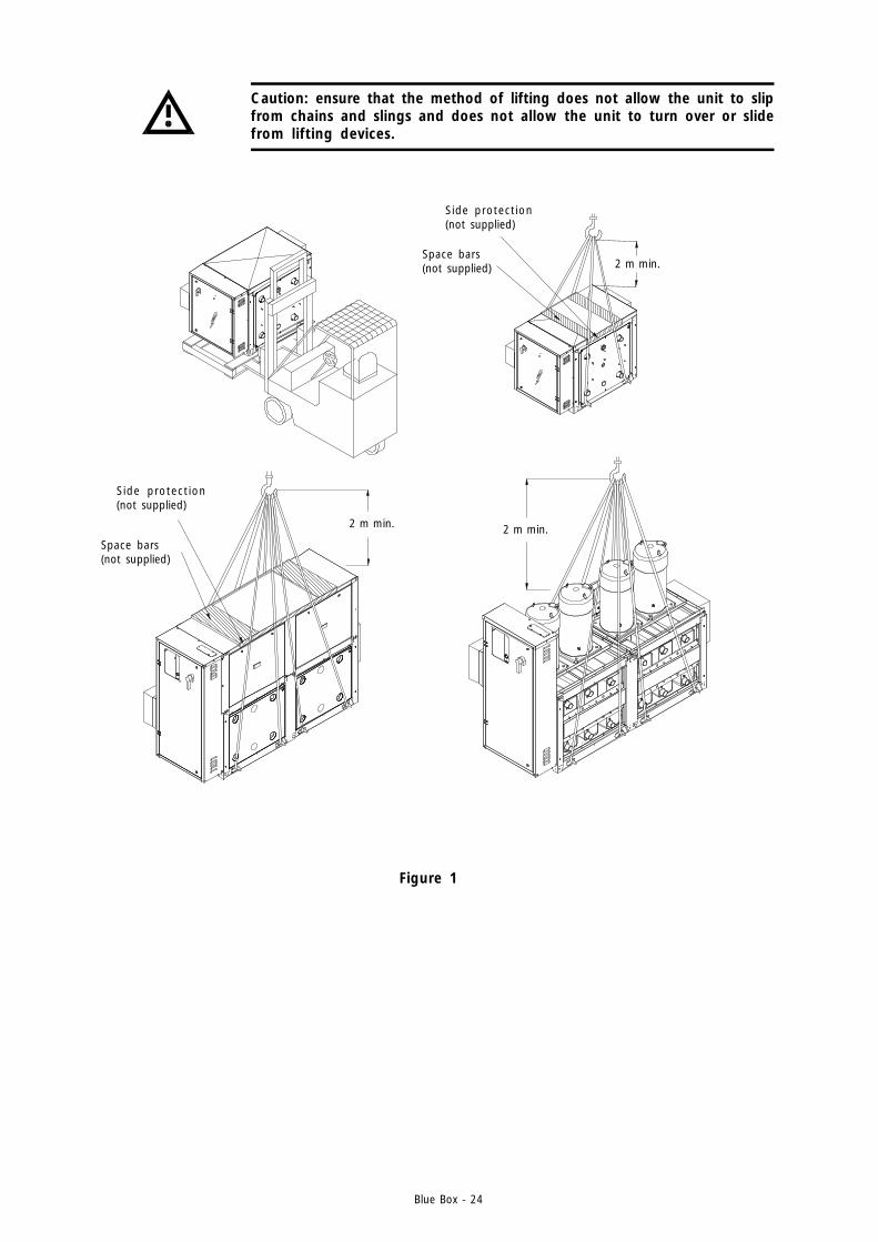
3.2 LIFTING AND SITE HANDLING
Avoid sudden movements and jolts when unloading and positioning the unit. Internal handling procedures mustbe conducted with care. Do not exert leverage on the components of the machine. The unit must be lifted byinserting steel tubes through the lifting attachments shown by the relative signs (yellow arrow).The unit must be lifted by harnessing it as shown in figure 1: use ropes or straps of sufficient length and spacerbars to avoid damage to the unit’s side panels and cover. Alternatively, the unit (with a maximum length less than3.5 m) can be lifted by a forklift truck, inserting the forks under the pallet.
The warranty will be invalid if the rules described in this manual are not observed and if any modifications aremade to the unit without prior authorisation of the manufacturer.
Blue Box - 24
Caution: ensure that the method of lifting does not allow the unit to slipfrom chains and slings and does not allow the unit to turn over or slidefrom lifting devices.
Figure 1
2 m min. 2 m min.
2 m min.
Side protection(not supplied)
Side protection(not supplied)
Space bars(not supplied)
Space bars(not supplied)

Blue Box - 25
3.3 UNPACKING
When unpacking the unit pay attention not to damage the unit. Packaging consists of different materials: wood,paper, nylon etc. Separate the materials and deliver to the proper gathering centre in order to reduce theirenvironmental impact.
3.4 LOCATION
The unit is suitable for inside locations where the temperature never falls below 4 °C.Unit vibration is very low. However it is advisable, to fit a rigid rubber pad between the floor or basement and unitbase-frame.If very low levels of vibration are required spring or rubber anti-vibration isolators should be installed. For detailssee paragraph 4.2.
Figure 2
Slab
Rubber pad
Blue Box - 26
4. INSTALLATION
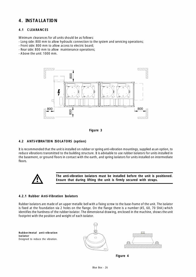
4.1 CLEARANCES
Minimum clearances for all units should be as follows:- Long side: 800 mm to allow hydraulic connection to the system and servicing operations;- Front side: 800 mm to allow access to electric board;- Rear side: 800 mm to allow maintenance operations;- Above the unit: 1000 mm.
Figure 3
Figure 4
800800 800
800
4.2 ANTI-VIBRATION ISOLATORS (option)
It is recommended that the unit is installed on rubber or spring anti-vibration mountings, supplied as an option, toreduce vibrations transmitted to the building structure. It is advisable to use rubber isolators for units installed inthe basement, or ground floors in contact with the earth, and spring isolators for units installed on intermediatefloors.
The anti-vibration isolators must be installed before the unit is positioned.Ensure that during lifting the unit is firmly secured with straps.
4.2.1 Rubber Anti-Vibration Isolators
Rubber isolators are made of an upper metallic bell with a fixing screw to the base-frame of the unit. The isolatoris fixed at the foundation via 2 holes on the flange. On the flange there is a number (45, 60, 70 ShA) whichidentifies the hardness of the rubber isolator. The dimensional drawing, enclosed in the machine, shows the unitfootprint with the position and weight of each isolator.
Rubber/meta l ant i -v ibrat ioni so la torDesigned to reduce the vibration.
Blue Box - 27
It is recommended that a safety valve is installed that can discharge thesystem in dangerous situations such as fire. The valve must be connectedto a vent pipe with a cross sectional area equal to or greater than thevalve and must be directed into a safe zone where people cannot beinjured.
In all units with four compressors the water inlets and outlets of thecondensers, evaporators and heat recovery heat exchangers must beconnected together with a manifold (available as an option).
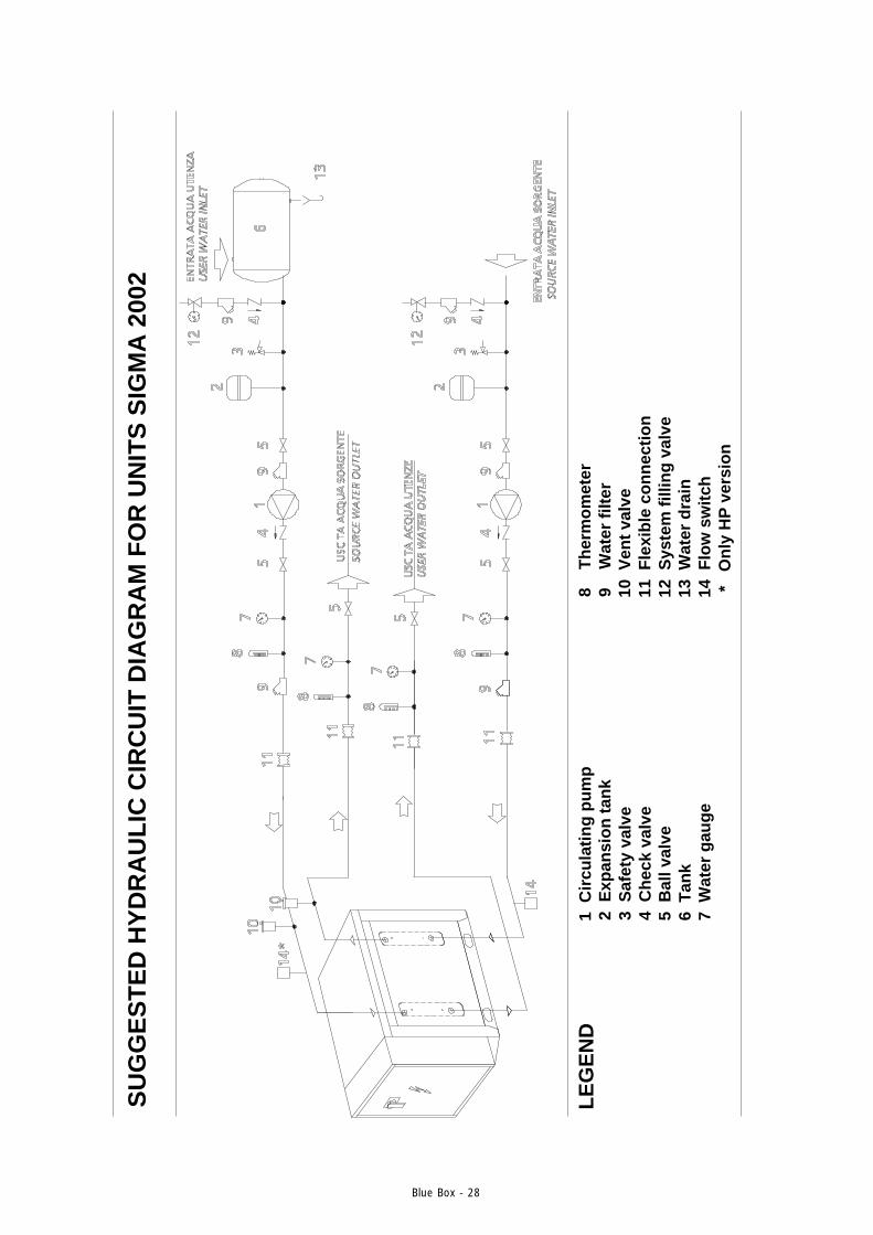
4.3 WATER PIPING CONNECTIONS
Unit water pipework must be installed in accordance with national and local regulation and codes.Follow the recommendations below when designing the water piping circuit (refer to the diagrams included in thismanual).
- Piping should be connected to the unit with flexible joints, to avoid vibration transmission and allow for thermalexpansion (the same procedure should be adopted for the circulating pumps).
- The following devices should be located on the piping system:- isolating/regulating valves, temperature gauges or thermometer pockets, pressure gauges or binder points
required for servicing operations.- Serviceable mesh strainer, with a filtration level no larger than 1mm, located on the unit inlet to prevent
debris from entering the heat exchangers.- vent valves, to be installed in the upper parts of the circuit, for air bleeding.- expansion device with accessories for circuit pressurisation, water thermal expansion compensation and
system filling.- unload valve and if necessary drainage tank for circuit emptying during maintenance and seasonal stop.
Blue Box - 28
SU
GG
ES
TE
D H
YD
RA
UL
IC C
IRC
UIT
DIA
GR
AM
FO
R U
NIT
S S
IGM
A 2
002
LE
GE
ND
1 C
ircu
lati
ng
pu
mp
2 E
xpan
sio
n t
ank
3 S
afet
y va
lve
4 C
hec
k va
lve
5 B
all v
alve
6 T
ank
7 W
ater
gau
ge
8
Th
erm
om
eter
9
Wat
er f
ilter
10 V
ent
valv
e11
Fle
xib
le c
on
nec
tio
n12
Sys
tem
fill
ing
val
ve13
Wat
er d
rain
14 F
low
sw
itch
*
On
ly H
P v
ersi
on
Blue Box - 29
4.4 EVAPORATOR WATER PIPE CONNECTIONS
The water inlet and outlet must be connected in the positions indicatedas labelled on the unit.
A constant water flow to the evaporator must be guaranteed at alloperating conditions to prevent l iquid refrigerant from entering thecompressor and causing irreparable damage.
Compressors start and stop often due to changes in cooling demand. In hydraulic circuits with low water volume,where the thermal inertia action is low, it is advisable to verify that the water volume equals or exceeds thefollowing ratio:
24 · QCOMPTOTM>= ---------------------
Nwhere:
M = system water content [kg] QCOMPTOT = unit cooling capacity [kW]
N = number of capacity steps
If the water volume does not reach the value given by the formula, it is advisable to provide the circuit with astorage vessel to increase the volume (tank + circuit) to match the result of the formula.The chilled water piping and storage vessel must be insulated to prevent condensation on the pipe surfaces andto avoid circuit performance losses.
On all units it is compulsory to install a flow switch. If a flow switch is notinstalled, on the evaporator leaving water connection, the warranty willbe terminated immediately. The flow switch must be installed, by thecontractor, on the evaporator water outlet connection labelled with:
If incorrectly connected the antifreeze thermostat will not operate and the evaporator may freeze.The hydraulic connections are threaded. The type and size are indicated on the dimensional drawings at the endof this manual.
HEAT PUMP units require a second flow switch is provided with the unit.This must be instal led, by the contractor, on the condenser outletconnection labelled with:
CONDENSER WATER
EVAPORATOR WATER
EVAPORATOR WATER

Blue Box - 30
The water inlet and outlet must be connected in the positions indicatedas labelled on the unit.
4.5 CONDENSER WATER PIPE CONNECTIONS
All units are provided with stainless steel threaded hydraulic connections. Sizes and locations are indicated in thedimensional data at the end of this manual.
For units equipped with more than one compressor, water inlets and outlets must be manifolded together.For connection locations and dimensions see the dimensional drawings at the end of this manual.
4.5.1 Pressostatic valveWhen using city water, rather than a cooling tower, it is recommended that a pressostatic valve is installed toensure the correct operation of the unit.The pressostatic valve is also recommended for closed circuit installations. This valve guarantees regular operationof the unit with changing condenser water conditions (for example when restarting after a weekend pause). Thepressostatic valve is absolutely necessary if the tower water entering into the condenser can decrease below 20°C (see figure 5). The pressostatic valve must provide a condensing pressure higher than 12.5 bar relative.Consult Blue Box for further information.
All units are equipped with plate heat exchangers. It is compulsory toinstall a metallic filter, on the water inlet piping, with a mesh not largerthan 1 mm. If a filter is not installed the warranty will be terminatedimmediately.
Caution: When making hydraulic connections never use naked flamesclose to or inside the unit.
We strongly recommend installing a pressure relief valve on the hydrauliccircuit. In the event of serious system breakdown or emergency (e.g.fire), the relief valve will make it possible to depressurise the systemthus forestalling possible pipe bursts. Always connect the relief valveoutlet to a pipe of diameter no smaller than the valve opening, and routeit to a location in which persons are protected from the jet of expelledwater.
IN ACQUA CONDENSAZIONECONDENSER WATER
ACQUA CONDENSAZIONE
Blue Box - 31
Refrigerant gas inlet
Refrigerant gas outlet
Condenser water outlet
Condenser water inlet
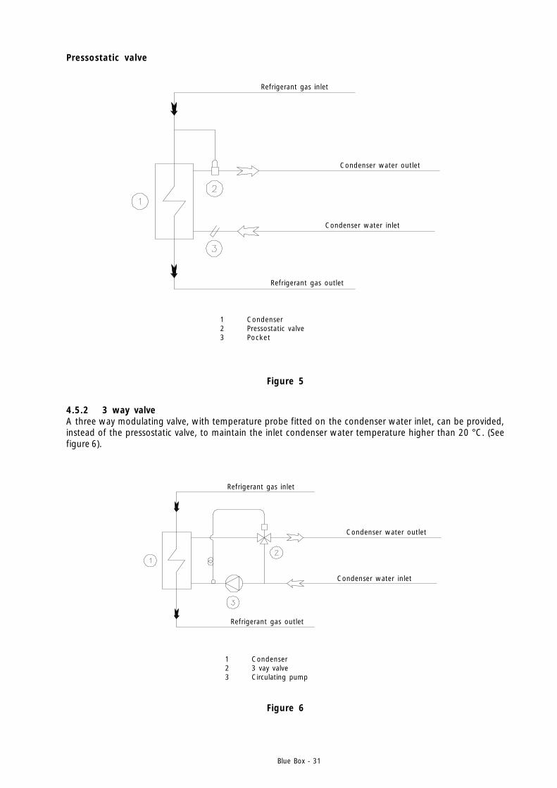
1 Condenser2 Pressostatic valve3 Pocket
Figure 5
Pressostatic valve
4.5.2 3 way valveA three way modulating valve, with temperature probe fitted on the condenser water inlet, can be provided,instead of the pressostatic valve, to maintain the inlet condenser water temperature higher than 20 °C. (Seefigure 6).
Refrigerant gas inlet
Refrigerant gas outlet
Condenser water outlet
Condenser water inlet
1 Condenser2 3 vay valve3 Circulating pump
Figure 6
Blue Box - 32
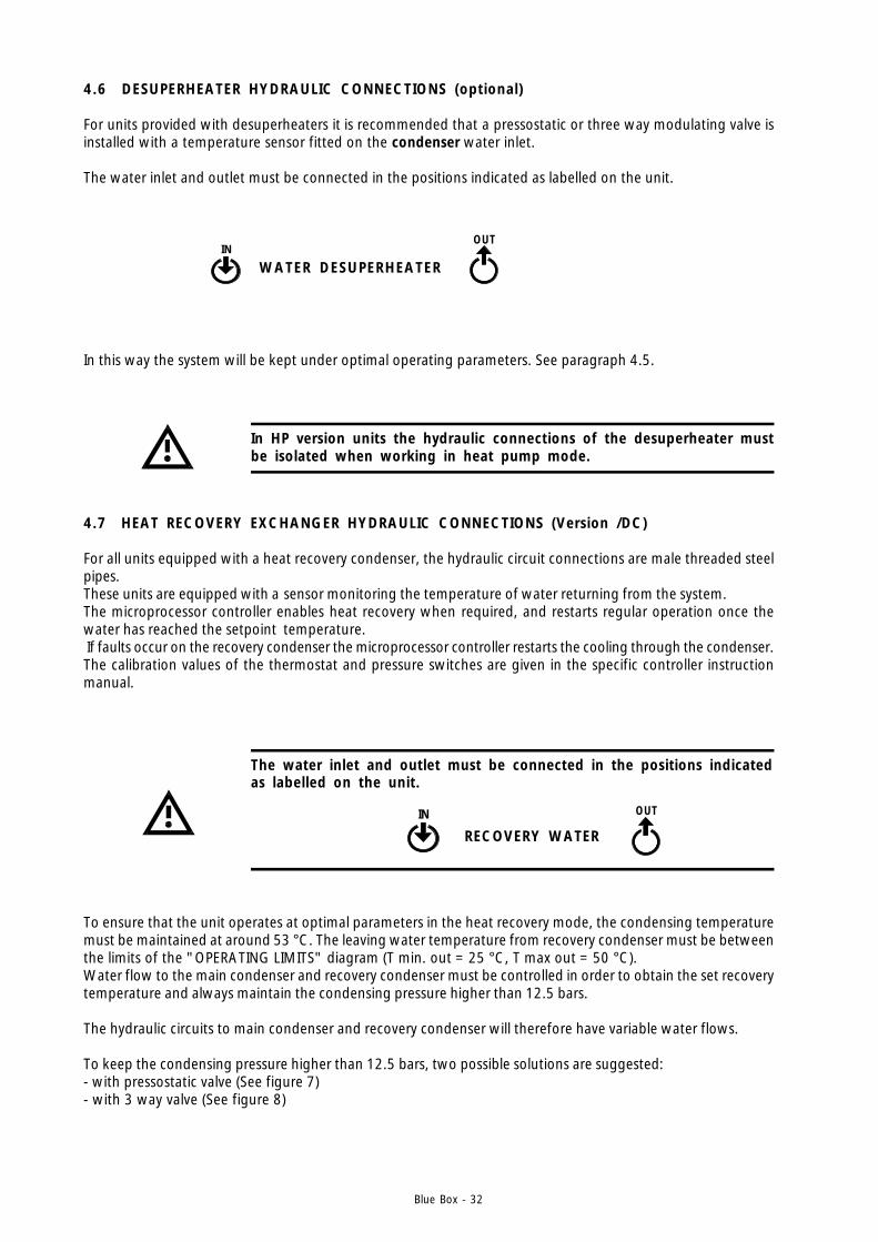
4.7 HEAT RECOVERY EXCHANGER HYDRAULIC CONNECTIONS (Version /DC)
For all units equipped with a heat recovery condenser, the hydraulic circuit connections are male threaded steelpipes.These units are equipped with a sensor monitoring the temperature of water returning from the system.The microprocessor controller enables heat recovery when required, and restarts regular operation once thewater has reached the setpoint temperature. If faults occur on the recovery condenser the microprocessor controller restarts the cooling through the condenser.The calibration values of the thermostat and pressure switches are given in the specific controller instructionmanual.
4.6 DESUPERHEATER HYDRAULIC CONNECTIONS (optional)
For units provided with desuperheaters it is recommended that a pressostatic or three way modulating valve isinstalled with a temperature sensor fitted on the condenser water inlet.
The water inlet and outlet must be connected in the positions indicated as labelled on the unit.
In this way the system will be kept under optimal operating parameters. See paragraph 4.5.
In HP version units the hydraulic connections of the desuperheater mustbe isolated when working in heat pump mode.
To ensure that the unit operates at optimal parameters in the heat recovery mode, the condensing temperaturemust be maintained at around 53 °C. The leaving water temperature from recovery condenser must be betweenthe limits of the "OPERATING LIMITS" diagram (T min. out = 25 °C, T max out = 50 °C).Water flow to the main condenser and recovery condenser must be controlled in order to obtain the set recoverytemperature and always maintain the condensing pressure higher than 12.5 bars.
The hydraulic circuits to main condenser and recovery condenser will therefore have variable water flows.
To keep the condensing pressure higher than 12.5 bars, two possible solutions are suggested:- with pressostatic valve (See figure 7)- with 3 way valve (See figure 8)
ACQUA DESURRISCALDATORE
The water inlet and outlet must be connected in the positions indicatedas labelled on the unit.
IN
ACQUA RECUPERO RECOVERY WATER
OUT
IN
ACQUA DESURRISCALDATOREWATER DESUPERHEATER
OUT
Blue Box - 33
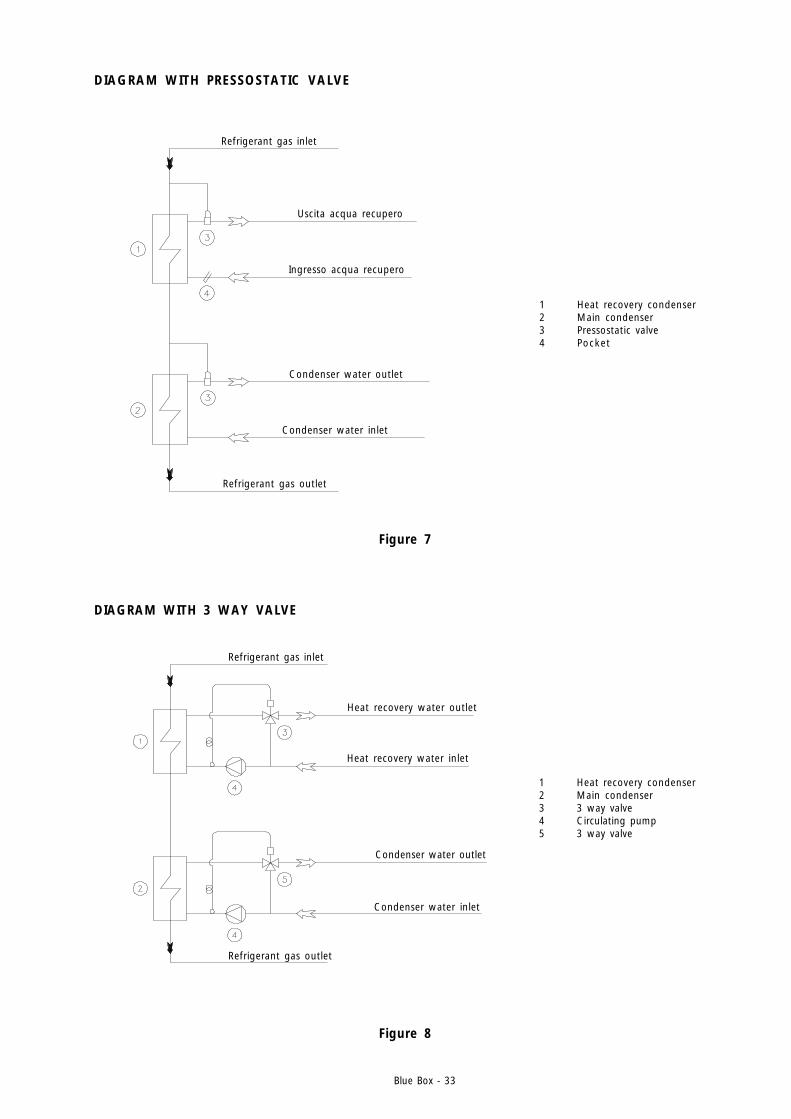
DIAGRAM WITH PRESSOSTATIC VALVE
1 Heat recovery condenser2 Main condenser3 Pressostatic valve4 Pocket
Refrigerant gas inlet
Refrigerant gas outlet
Ingresso acqua recupero
Uscita acqua recupero
Condenser water inlet
Condenser water outlet
Figure 7
1 Heat recovery condenser2 Main condenser3 3 way valve4 Circulating pump5 3 way valve
DIAGRAM WITH 3 WAY VALVE
Figure 8
Refrigerant gas inlet
Refrigerant gas outlet
Condenser water inlet
Condenser water outlet
Heat recovery water inlet
Heat recovery water outlet
Blue Box - 34
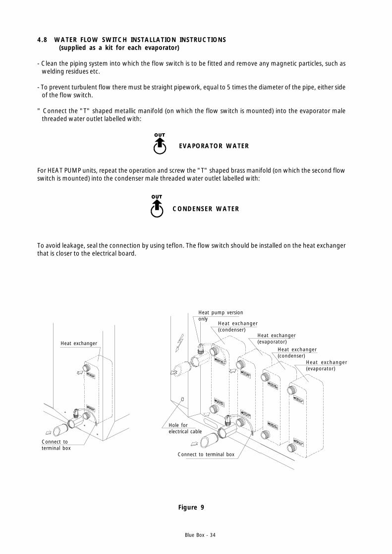
4.8 WATER FLOW SWITCH INSTALLATION INSTRUCTIONS (supplied as a kit for each evaporator)
- Clean the piping system into which the flow switch is to be fitted and remove any magnetic particles, such aswelding residues etc.
- To prevent turbulent flow there must be straight pipework, equal to 5 times the diameter of the pipe, either sideof the flow switch.
" Connect the "T" shaped metallic manifold (on which the flow switch is mounted) into the evaporator malethreaded water outlet labelled with:
Figure 9
For HEAT PUMP units, repeat the operation and screw the "T" shaped brass manifold (on which the second flowswitch is mounted) into the condenser male threaded water outlet labelled with:
To avoid leakage, seal the connection by using teflon. The flow switch should be installed on the heat exchangerthat is closer to the electrical board.
Heat exchanger
Connect toterminal box
Heat pump versiononly
Heat exchanger(condenser)
Heat exchanger(evaporator)
Hole forelectrical cable
Connect to terminal box
Heat exchanger(condenser)
Heat exchanger(evaporator)
CONDENSER WATER
EVAPORATOR WATER

Blue Box - 35
Warning: When connecting or fabricating pipework never work with nakedflames either inside the unit or in the immediate vicinity of the unit.
- The flow switch must be tightened on the “T” shaped metallic manifold by the plastic knurled union nut. Checkthat the arrow located on the upper side is pointing in the direction of flow.
- Be sure to fit the O-ring seal, through the brass manifold and the plastic ring nut. The O-ring seal is supplied ina plastic cover to protect the flow switch shaft.
- Connect the flow switch to the other end of the “T” manifold.
- Route the flow switch electrical cable through the hole in the unit structure and run it to the electrical panel byascending the upright in the machine interior. Connect the flow switch to terminals 1-14 as indicated on theelectrical drawing.
- The flow switch can be removed by screwing out the plastic knurled union nut. In order to reassemble it, ensurethat the o-ring seal is positioned in the proper location. (See figure10).
Figure 10
Arrow
Flow switch
O Ring
Electric cable
Plastic union nut
“T” shaped brass manifold
Flow direction
Blue Box - 36
4.9 CONNECTIONS FOR VERSION LE (MOTOCONDENSING) AND LC (MOTOEVAPORATING)
4.9.1 Refrigerant connections
Version LE units (motocondensing) and LE (motoevaporating) must be connected with refrigerant pipelines.
4.9.2 Route of pipes and maximum distance between sections
For units types with separate sections, the route followed by refrigerant lines depends on the location of thesections and the characteristics of the surrounding building structure.Pipe runs should be as short as possible to limit the pressure drop and the refrigerant charge volume. Themaximum permissible pipeline length is 30 metres.If this limits cannot be adhered to contact Blue Box for further information.
4.9.3 Procedures to follow when sizing refrigerant lines
Depending on the relative position of the sections, there are certain procedures to follow when installing therefrigerant line.
The diameter of pipes for versions LE and LC can be obtained from tables 1, 2 and 3, according to the selectedmodel and length of connecting pipes.
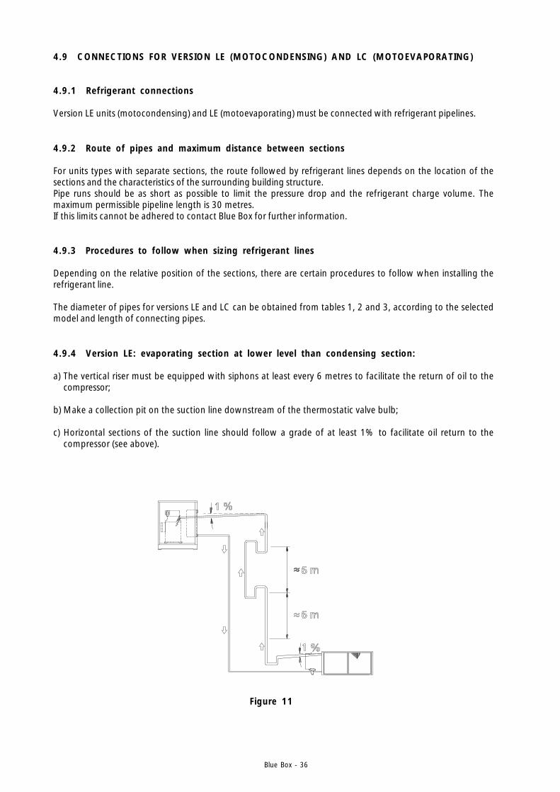
4.9.4 Version LE: evaporating section at lower level than condensing section:
a) The vertical riser must be equipped with siphons at least every 6 metres to facilitate the return of oil to thecompressor;
b) Make a collection pit on the suction line downstream of the thermostatic valve bulb;
c) Horizontal sections of the suction line should follow a grade of at least 1% to facilitate oil return to thecompressor (see above).
Figure 11
Blue Box - 37
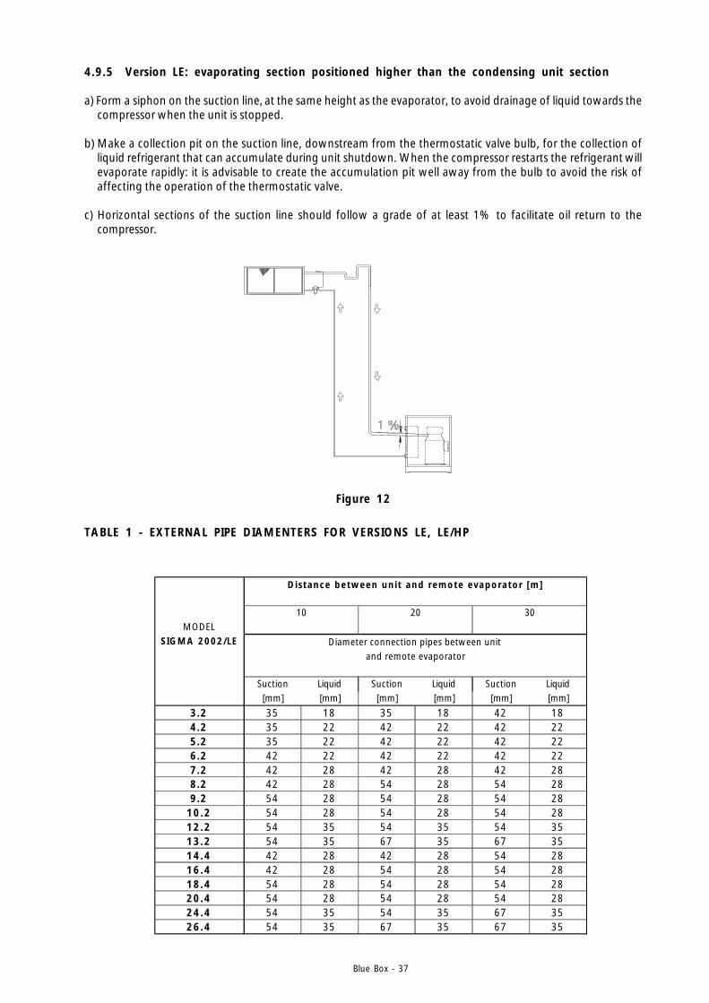
4.9.5 Version LE: evaporating section positioned higher than the condensing unit section
a) Form a siphon on the suction line, at the same height as the evaporator, to avoid drainage of liquid towards thecompressor when the unit is stopped.
b) Make a collection pit on the suction line, downstream from the thermostatic valve bulb, for the collection ofliquid refrigerant that can accumulate during unit shutdown. When the compressor restarts the refrigerant willevaporate rapidly: it is advisable to create the accumulation pit well away from the bulb to avoid the risk ofaffecting the operation of the thermostatic valve.
c) Horizontal sections of the suction line should follow a grade of at least 1% to facilitate oil return to thecompressor.
TABLE 1 - EXTERNAL PIPE DIAMENTERS FOR VERSIONS LE, LE/HP
MODELSIGMA 2002/LE
Suction Liquid Suction Liquid Suction Liquid[mm] [mm] [mm] [mm] [mm] [mm]
3.2 35 18 35 18 42 184.2 35 22 42 22 42 225.2 35 22 42 22 42 226.2 42 22 42 22 42 227.2 42 28 42 28 42 288.2 42 28 54 28 54 289.2 54 28 54 28 54 28
10.2 54 28 54 28 54 2812.2 54 35 54 35 54 3513.2 54 35 67 35 67 3514.4 42 28 42 28 54 2816.4 42 28 54 28 54 2818.4 54 28 54 28 54 2820.4 54 28 54 28 54 2824.4 54 35 54 35 67 3526.4 54 35 67 35 67 35
Diameter connection pipes between unit and remote evaporator
Distance between unit and remote evaporator [m]
10 20 30
Figure 12

Blue Box - 38
4.9.6 Version LC: remote condenser above the evaporating unit:
a) Make a trap on the supply line, immediately downstream from the compressor, to collect the liquid refrigerantwhich can develop during unit shutdown and could irreparably damage the compressor.
b) Install siphons at least every 6 metres on vertical upward sections of pipelines in order to facilitate the return ofoil to the compressor.
c) Ensure that there is a gradient of at least 1% on horizontal sections of the refrigerant lines to facilitate oildrainage in the correct direction of the flow.
d) Install a non return valve close to condenser inlet, to avoid liquid refrigerant entering the compressor during unitshutdown. This must be done with the unit off and when the ambient temperature of the condenser is higherthan that of the compressor.
Figure 13
4.9.7 Version LC: remote air cooled condenser below the evaporating unit:There are no special suggestions for this installation.It is however advisable to install a non return valve close to the compressor inlet, to avoid liquid refrigerantentering the compressor during unit shutdown. This must be done with the unit off and when the ambienttemperature of the condenser is higher than that of the compressor.
Figure 14
Blue Box - 39
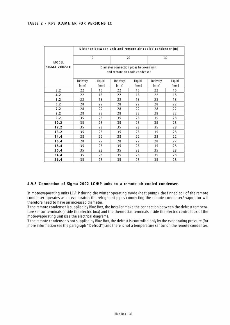
4.9.8 Connection of Sigma 2002 LC/HP units to a remote air cooled condenser.
In motoevaporating units LC/HP during the winter operating mode (heat pump), the finned coil of the remotecondenser operates as an evaporator; the refrigerant pipes connecting the remote condenser/evaporator willtherefore need to have an increased diameter.If the remote condenser is supplied by Blue Box, the installer make the connection between the defrost tempera-ture sensor terminals (inside the electric box) and the thermostat terminals inside the electric control box of themotoevaporating unit (see the electrical diagram).If the remote condenser is not supplied by Blue Box, the defrost is controlled only by the evaporating pressure (formore information see the paragraph “Defrost”) and there is not a temperature sensor on the remote condenser.
TABLE 2 - PIPE DIAMETER FOR VERSIONS LC
MODELSIGMA 2002/LC
Delivery Liquid Delivery Liquid Delivery Liquid[mm] [mm] [mm] [mm] [mm] [mm]
3.2 22 16 22 16 22 164.2 22 18 22 18 22 185.2 22 18 22 18 28 186.2 28 22 28 22 28 227.2 28 22 28 22 28 228.2 28 22 28 22 28 229.2 35 28 35 28 35 28
10.2 35 28 35 28 35 2812.2 35 28 35 28 35 2813.2 35 28 35 28 35 2814.4 28 22 28 22 28 2216.4 28 22 28 22 28 2218.4 35 28 35 28 35 2820.4 35 28 35 28 35 2824.4 35 28 35 28 35 2826.4 35 28 35 28 35 28
30
Diameter connection pipes between unit
Distance between unit and remote a ir cooled condenser [m]
and remote air coole condenser
10 20
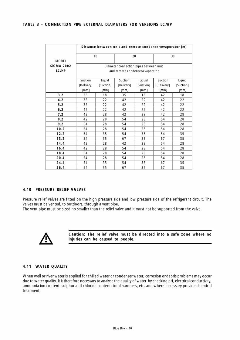
Blue Box - 40
4.10 PRESSURE RELIEF VALVES
Pressure relief valves are fitted on the high pressure side and low pressure side of the refrigerant circuit. Thevalves must be vented, to outdoors, through a vent pipe.The vent pipe must be sized no smaller than the relief valve and it must not be supported from the valve.
Caution: The relief valve must be directed into a safe zone where noinjuries can be caused to people.
4.11 WATER QUALITY
When well or river water is applied for chilled water or condenser water, corrosion or debris problems may occurdue to water quality. It is therefore necessary to analyse the quality of water by checking pH, electrical conductivity,ammonia ion content, sulphur and chloride content, total hardness, etc. and where necessary provide chemicaltreatment.
TABLE 3 - CONNECTION PIPE EXTERNAL DIAMETERS FOR VERSIONS LC/HP
MODELSIGMA 2002
LC/HP
Suction Liquid Suction Liquid Suction Liquid[Delivery] [Suction] [Delivery] [Suction] [Delivery] [Suction]
[mm] [mm] [mm] [mm] [mm] [mm]
3.2 35 18 35 18 42 184.2 35 22 42 22 42 225.2 35 22 42 22 42 226.2 42 22 42 22 42 227.2 42 28 42 28 42 288.2 42 28 54 28 54 289.2 54 28 54 28 54 28
10.2 54 28 54 28 54 2812.2 54 35 54 35 54 3513.2 54 35 67 35 67 3514.4 42 28 42 28 54 2816.4 42 28 54 28 54 2818.4 54 28 54 28 54 2820.4 54 28 54 28 54 2824.4 54 35 54 35 67 3526.4 54 35 67 35 67 35
Diameter connection pipes between unit and remote condenser/evaporator
Distance between unit and remote condenser/evaporator [m]
10 20 30
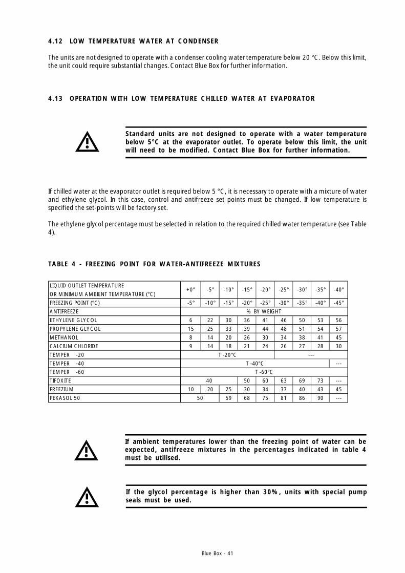
Blue Box - 41
TABLE 4 - FREEZING POINT FOR WATER-ANTIFREEZE MIXTURES
If ambient temperatures lower than the freezing point of water can beexpected, antifreeze mixtures in the percentages indicated in table 4must be utilised.
LIQUID OUTLET TEMPERATURE
OR MINIMUM AMBIENT TEMPERATURE (°C)
FREEZING POINT (°C) -5° -10° -15° -20° -25° -30° -35° -40° -45°
ANTIFREEZE
ETHYLENE GLYCOL 6 22 30 36 41 46 50 53 56
PROPYLENE GLYCOL 15 25 33 39 44 48 51 54 57
METHANOL 8 14 20 26 30 34 38 41 45
CALCIUM CHLORIDE 9 14 18 21 24 26 27 28 30
TEMPER -20
TEMPER -40 ---TEMPER -60
TIFOXITE 50 60 63 69 73 ---
FREEZIUM 10 20 25 30 34 37 40 43 45
PEKASOL 50 59 68 75 81 86 90 ---
-40°
% BY WEIGHT
40
50
T -20°C
T -40°CT -60°C
---
-20° -25° -30° -35°+0° -5° -10° -15°
If the glycol percentage is higher than 30%, units with special pumpseals must be used.
4.12 LOW TEMPERATURE WATER AT CONDENSER
The units are not designed to operate with a condenser cooling water temperature below 20 °C. Below this limit,the unit could require substantial changes. Contact Blue Box for further information.
If chilled water at the evaporator outlet is required below 5 °C, it is necessary to operate with a mixture of waterand ethylene glycol. In this case, control and antifreeze set points must be changed. If low temperature isspecified the set-points will be factory set.
The ethylene glycol percentage must be selected in relation to the required chilled water temperature (see Table4).
Standard units are not designed to operate with a water temperaturebelow 5°C at the evaporator outlet. To operate below this limit, the unitwill need to be modified. Contact Blue Box for further information.
4.13 OPERATION WITH LOW TEMPERATURE CHILLED WATER AT EVAPORATOR
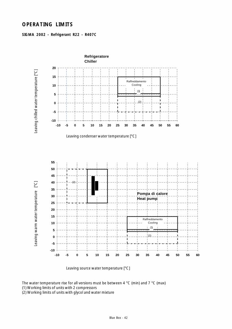
Blue Box - 42
OPERATING LIMITS
SIGMA 2002 - Refrigerant R22 - R407C
The water temperature rise for all versions must be between 4 °C (min) and 7 °C (max)(1) Working limits of units with 2 compressors(2) Working limits of units with glycol and water mixture
Leaving condenser water temperature [°C]
Leav
ing
chill
ed w
ater
tem
pera
ture
[°C
]
Leaving source water temperature [°C]
Leav
ing
war
m w
ater
tem
pera
ture
[°
C]
(1)
RaffreddamentoCooling
-10
-5
0
5
10
15
20
-10 -5 0 5 10 15 20 25 30 35 40 45 50 55 60
Refrigeratore Chiller
(2)
RaffreddamentoCooling
(1)
-10
-5
0
5
10
15
20
25
30
35
40
45
50
55
-10 -5 0 5 10 15 20 25 30 35 40 45 50 55 60
Pompa di caloreHeat pump
(2)
(2)
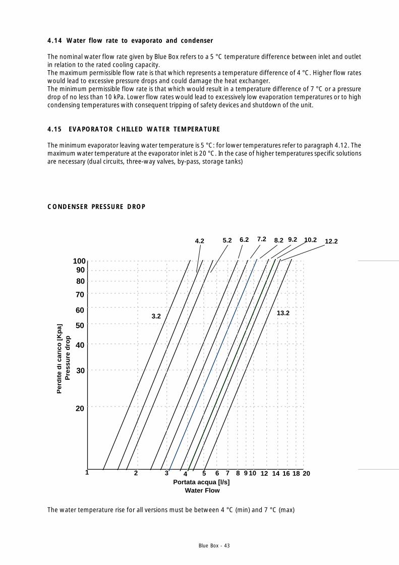
Blue Box - 43
CONDENSER PRESSURE DROP
The water temperature rise for all versions must be between 4 °C (min) and 7 °C (max)
4.14 Water flow rate to evaporato and condenser
The nominal water flow rate given by Blue Box refers to a 5 °C temperature difference between inlet and outletin relation to the rated cooling capacity.The maximum permissible flow rate is that which represents a temperature difference of 4 °C. Higher flow rateswould lead to excessive pressure drops and could damage the heat exchanger.The minimum permissible flow rate is that which would result in a temperature difference of 7 °C or a pressuredrop of no less than 10 kPa. Lower flow rates would lead to excessively low evaporation temperatures or to highcondensing temperatures with consequent tripping of safety devices and shutdown of the unit.
4.15 EVAPORATOR CHILLED WATER TEMPERATURE
The minimum evaporator leaving water temperature is 5 °C: for lower temperatures refer to paragraph 4.12. Themaximum water temperature at the evaporator inlet is 20 °C. In the case of higher temperatures specific solutionsare necessary (dual circuits, three-way valves, by-pass, storage tanks)
20
30
50
60
70
8090
100
40
1 64
10.2
2
3.2
4.2 5.2 6.2 7.2 8.2 9.2 12.2
8 10 12 14 16 18 20
13.2
53 7 9Portata acqua [l/s]
Water Flow
Per
dit
e d
i car
ico
[K
pa]
Pre
ssu
re d
rop

Blue Box - 44
CONDENSER PRESSURE DROP
20
30
50
60
70
80
90
100
40
2
16.4
4 106 8
14.4
18.4 20.4
9
24.4
26.4
1214 161820 25227 11Portata acqua [l/s]
Water Flow
Per
dit
a d
i car
ico
[K
pa]
P
ress
ure
dro
p
The water temperature rise for all versions must be between 4 °C (min) and 7 °C (max)
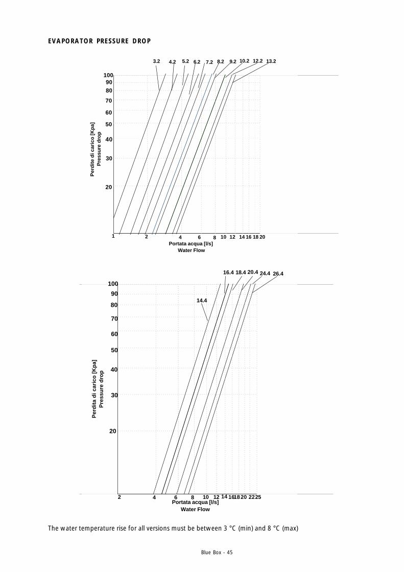
Blue Box - 45
EVAPORATOR PRESSURE DROP
20
30
50
60
70
8090
100
40
1 64
10.2
2
3.2 4.2 5.2 6.2 7.2 8.2 9.2 12.2
8 10 12 14 16 18 20
13.2
Portata acqua [l/s] Water Flow
Per
dit
e d
i car
ico
[Kp
a] P
ress
ure
drop
20
30
50
60
70
80
90
100
40
2
16.4
4 106 8
14.4
18.4 20.4 24.4 26.4
12 14 161820 2522Portata acqua [l/s]
Water Flow
Per
dit
a d
i car
ico
[K
pa]
P
ress
ure
dro
p
The water temperature rise for all versions must be between 3 °C (min) and 8 °C (max)
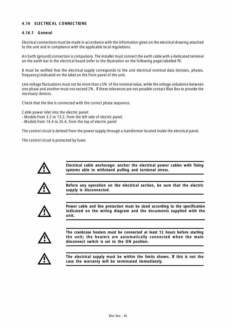
Blue Box - 46
Electrical connections must be made in accordance with the information given on the electrical drawing attachedto the unit and in compliance with the applicable local regulations.
An Earth (ground) connection is compulsory. The installer must connect the earth cable with a dedicated terminalon the earth bar in the electrical board (refer to the illustration on the following page) labelled PE.
It must be verified that the electrical supply corresponds to the unit electrical nominal data (tension, phases,frequency) indicated on the label on the front panel of the unit.
Line voltage fluctuations must not be more than ±5% of the nominal value, while the voltage unbalance betweenone phase and another must not exceed 2%. If these tolerances are not possible contact Blue Box to provide thenecessary devices.
Check that the line is connected with the correct phase sequence.
Cable power inlet into the electric panel:- Models from 3.2 to 13.2, from the left side of electric panel.- Models from 14.4 to 26.4, from the top of electric panel
The control circuit is derived from the power supply through a transformer located inside the electrical panel.
The control circuit is protected by fuses.
4.16 ELECTRICAL CONNECTIONS
4.16.1 General
Before any operation on the electrical section, be sure that the electricsupply is disconnected.
Power cable and line protection must be sized according to the specificationindicated on the wiring diagram and the documents supplied with theunit.
The electrical supply must be within the limits shown. If this is not thecase the warranty will be terminated immediately.
Electrical cable anchorage: anchor the electrical power cables with fixingsystems able to withstand pulling and torsional stress.
The crankcase heaters must be connected at least 12 hours before startingthe unit ; the heaters are automatical ly connected when the maindisconnect switch is set to the ON position.
Blue Box - 47
4.16.5 Circulating pump electrical connections
The external interlocks of unit must close for the unit to operate. The normally open external water circulatingpump contactor terminals must be wired in series with terminals 1 and 2, on the unit control panel, to ensure thatthe chiller can only start after the pump is in operation.
Turn on the pump before the unit starts and stop it after the unit hasstopped (recommended time delay: 60 sec).
4.16.3 Potential free contacts
The following potential free contacts are available:- 1 potential free contact for general alarm (terminals 100 - 101 - 102)- 1 potential free contact for each compressor (option)
4.16.4 Flow switch electrical connections
Flow switch electrical connections (see paragraph 4.5 ) must be connected to terminal 1-14 for chiller units.For heat pump units evaporator (user exchanger) flow switch must be connected to terminals 1-15 while condenser(source exchanger) flow switch must be connected to terminals 14-15.
4.16.6 External interlock
If a remote ON-OFF is required connect the external interlock to terminals 1 and 2. If an external interlock is notrequired, bridge therminals 1 and 2 to enable the unit to start.
4.16.2 Power supply to crankcase heaters
1) Close the main disconnect switch by turning it from position "0" to position "1"2) Check that the word "OFF" is shown on the display3) Ensure that the unit is in "OFF" status and that the external enabling contact is open4) After a few moments, if the phase sequence is incorrect the alarm "INCORRECT PHASE SEQUENCE" will be
displayed (4-compressor models from 14.4 to 26.4 only, with pCO2 controller). In this case invert the connectionsof two of the power line phase wires.
5) Leave the unit in this condition for at least 12 hours to allow the crankcase heaters to perform their function
4.17 MICROPROCESSOR CONTROLLERS
Chillers in the SIGMA 2002 series with 2 scroll compressors, models from 3.2 to 13.2, are equipped with themCHILLER type microprocessor controller.
Chillers in the SIGMA 2002 series with 4 scroll compressors, models from 14.4 to 26.4, are equipped with thepCO2 microprocessor controller.
Blue Box - 48
4.17.1 Microprocessor controller for /LE and HP/LE versions
- Versions SIGMA 2002 /LE and SIGMA 2002 HP/LE with two compressors are equipped with an mCHILLERcontroller.
- Versions SIGMA 2002 /LE and SIGMA 2002 HP/LE with four compressors do not have an integral controller andtherefore an external controller, or thermostats, must be connected to the auxiliary terminals 1-21, 1-31, 1-41and 1-51.
Consult the electrical diagram attached to the unit.
4.17.2 RS485 serial interface (optional)
All units can be equipped with a serial interface board for supervision or remote diagnosticfunctions via a computer.
The serial interface board plugs into a dedicated slot on the connection board.Connection to the supervision or remote diagnostics serial line is executed in compliance with standard RS485and is achieved by means of the serial interface boards.
Models from 3.2 to 13.2 with two scroll compressors and mCHILLER controller
When the serial interface board is inserted the Carel communications protocol is available.A conversion gateway is required for Modbus-jbus and BacNet protocols.
Models from 14.4 to 26.4 with four scroll compressors and pCO2 controller
When the serial interface board is inserted the following communications protocols are available: Carel, Modbus-jbus, BacNet. If a connection is to be made with networks that utilise the Lon-Talk protocol, a dedicated boardmust be installed.In this case, a conversion gateway is not required.

Blue Box - 49
ELECTRIC PANEL LAY OUT
SIGMA 2002 - SIGMA 2002 HP - SIGMA 2002 LE - SIGMA 2002 LE/HP - SIGMA 2002 LC -SIGMA 2002 LC/HP - Models 3.2 - 13.2
Models 3.2 - 10.2
Models 12.2 - 13.2
OPTIONAL
KM1 CONTACTOR COMPRESSOR 1KM2 CONTACTOR COMPRESSOR 2KM41 CONTACT. CAPACITOR POW. FACT. CORRECT. 1KM42 CONTACT. CAPACITOR POW. FACT. CORRECT. 2FU1 FUSES COMPRESSOR 1FU2 FUSES COMPRESSOR 2QS1 MAIN SWITCHFU41 FUSES CAPACITOR POW. FACT. CORRECT. 1FU42 FUSES CAPACITOR POW. FACT. CORRECT. 2FU56 PHASE SEQ. RELAY FUSESFU50 FUSES AUX. TRANSFORMERFU51 AUX. CIRCUIT FUSESFU52 FUSE CONTROLKA5 PHASE SEQUENCE RELAYTC1 AUX. TRANSFORMERKA1 VOLTAGE RELAY
KM1 CONTACTOR COMPRESSOR 1KM2 CONTACTOR COMPRESSOR 2KM41 CONTACT. CAPACITOR POW. FACT. CORRECT. 1KM42 CONTACT. CAPACITOR POW. FACT. CORRECT. 2FU41 FUSES CAPACITOR POW. FACT. CORRECT. 1FU42 FUSES CAPACITOR POW. FACT. CORRECT. 2FU56 PHASE SEQ. RELAY FUSESFU50 FUSES AUX. TRANSFORMERFU51 AUX. CIRCUIT FUSESFU52 FUSE CONTROLKA5 PHASE SEQUENCE RELAYKA1 VOLTAGE RELAYFU1 FUSES COMPRESSOR 1FU2 FUSES COMPRESSOR 2QS1 MAIN SWITCHTC1 AUX. TRANSFORMER
A4 BOARD FOR REMOTE CONTROLA2 CONTROL BOARDA3 EXPANSION BOARD 2 COMPRESSORB
OPTIONAL
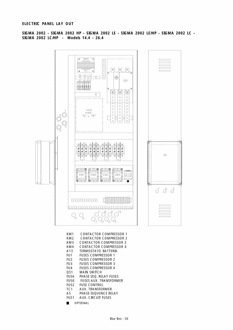
Blue Box - 50
OPTIONAL
KM1 CONTACTOR COMPRESSOR 1KM2 CONTACTOR COMPRESSOR 2KM3 CONTACTOR COMPRESSOR 3KM4 CONTACTOR COMPRESSOR 4A13 TERMOSTATO BATTERIAFU1 FUSES COMPRESSOR 1FU2 FUSES COMPRESSOR 2FU3 FUSES COMPRESSOR 3FU4 FUSES COMPRESSOR 4QS1 MAIN SWITCHFU56 PHASE SEQ. RELAY FUSESFU50 FUSES AUX. TRANSFORMERFU52 FUSE CONTROLTC1 AUX. TRANSFORMERA5 PHASE SEQUENCE RELAYFU51 AUX. CIRCUIT FUSES
ELECTRIC PANEL LAY OUT
SIGMA 2002 - SIGMA 2002 HP - SIGMA 2002 LE - SIGMA 2002 LE/HP - SIGMA 2002 LC -SIGMA 2002 LC/HP - Models 14.4 - 26.4
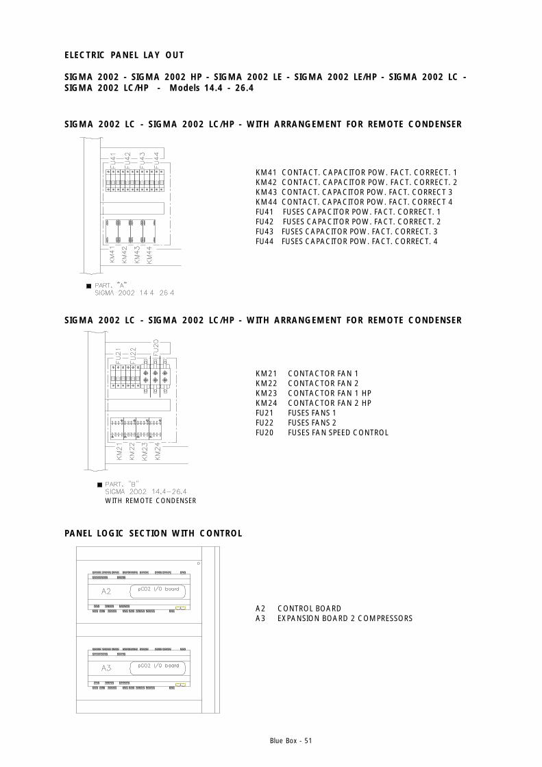
Blue Box - 51
KM41 CONTACT. CAPACITOR POW. FACT. CORRECT. 1KM42 CONTACT. CAPACITOR POW. FACT. CORRECT. 2KM43 CONTACT. CAPACITOR POW. FACT. CORRECT 3KM44 CONTACT. CAPACITOR POW. FACT. CORRECT 4FU41 FUSES CAPACITOR POW. FACT. CORRECT. 1FU42 FUSES CAPACITOR POW. FACT. CORRECT. 2FU43 FUSES CAPACITOR POW. FACT. CORRECT. 3FU44 FUSES CAPACITOR POW. FACT. CORRECT. 4
KM21 CONTACTOR FAN 1KM22 CONTACTOR FAN 2KM23 CONTACTOR FAN 1 HPKM24 CONTACTOR FAN 2 HPFU21 FUSES FANS 1FU22 FUSES FANS 2FU20 FUSES FAN SPEED CONTROL
SIGMA 2002 LC - SIGMA 2002 LC/HP - WITH ARRANGEMENT FOR REMOTE CONDENSER
SIGMA 2002 LC - SIGMA 2002 LC/HP - WITH ARRANGEMENT FOR REMOTE CONDENSER
PANEL LOGIC SECTION WITH CONTROL
A2 CONTROL BOARDA3 EXPANSION BOARD 2 COMPRESSORS
ELECTRIC PANEL LAY OUT
SIGMA 2002 - SIGMA 2002 HP - SIGMA 2002 LE - SIGMA 2002 LE/HP - SIGMA 2002 LC -SIGMA 2002 LC/HP - Models 14.4 - 26.4
WITH REMOTE CONDENSER
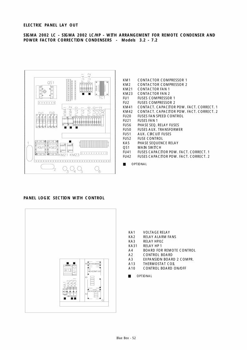
Blue Box - 52
ELECTRIC PANEL LAY OUT
SIGMA 2002 LC - SIGMA 2002 LC/HP - WITH ARRANGEMENT FOR REMOTE CONDENSER ANDPOWER FACTOR CORRECTION CONDENSERS - Models 3.2 - 7.2
OPTIONAL
KM1 CONTACTOR COMPRESSOR 1KM2 CONTACTOR COMPRESSOR 2KM21 CONTACTOR FAN 1KM23 CONTACTOR FAN 2FU1 FUSES COMPRESSOR 1FU2 FUSES COMPRESSOR 2KM41 CONTACT. CAPACITOR POW. FACT. CORRECT. 1KM42 CONTACT. CAPACITOR POW. FACT. CORRECT. 2FU20 FUSES FAN SPEED CONTROLFU21 FUSES FAN 1FU56 PHASE SEQ. RELAY FUSESFU50 FUSES AUX. TRANSFORMERFU51 AUX. CIRCUIT FUSESFU52 FUSE CONTROLKA5 PHASE SEQUENCE RELAYQS1 MAIN SWITCHFU41 FUSES CAPACITOR POW. FACT. CORRECT. 1FU42 FUSES CAPACITOR POW. FACT. CORRECT. 2
KA1 VOLTAGE RELAYKA2 RELAY ALARM FANSKA3 RELAY HP/LCKA31 RELAY HP 1A4 BOARD FOR REMOTE CONTROLA2 CONTROL BOARDA3 EXPANSION BOARD 2 COMPR.A13 THERMOSTAT COILA10 CONTROL BOARD ON/OFF
OPTIONAL
PANEL LOGIC SECTION WITH CONTROL
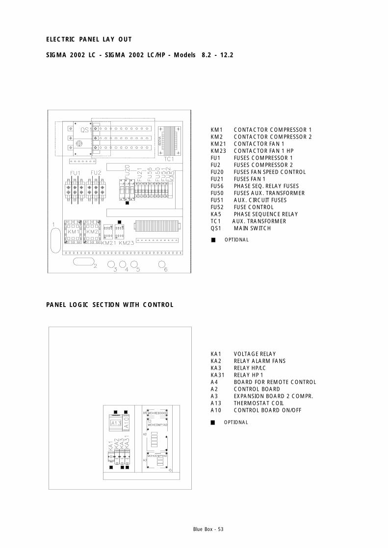
Blue Box - 53
KA1 VOLTAGE RELAYKA2 RELAY ALARM FANSKA3 RELAY HP/LCKA31 RELAY HP 1A4 BOARD FOR REMOTE CONTROLA2 CONTROL BOARDA3 EXPANSION BOARD 2 COMPR.A13 THERMOSTAT COILA10 CONTROL BOARD ON/OFF
KM1 CONTACTOR COMPRESSOR 1KM2 CONTACTOR COMPRESSOR 2KM21 CONTACTOR FAN 1KM23 CONTACTOR FAN 1 HPFU1 FUSES COMPRESSOR 1FU2 FUSES COMPRESSOR 2FU20 FUSES FAN SPEED CONTROLFU21 FUSES FAN 1FU56 PHASE SEQ. RELAY FUSESFU50 FUSES AUX. TRANSFORMERFU51 AUX. CIRCUIT FUSESFU52 FUSE CONTROLKA5 PHASE SEQUENCE RELAYTC1 AUX. TRANSFORMERQS1 MAIN SWITCH
OPTIONAL
OPTIONAL
ELECTRIC PANEL LAY OUT
SIGMA 2002 LC - SIGMA 2002 LC/HP - Models 8.2 - 12.2
PANEL LOGIC SECTION WITH CONTROL
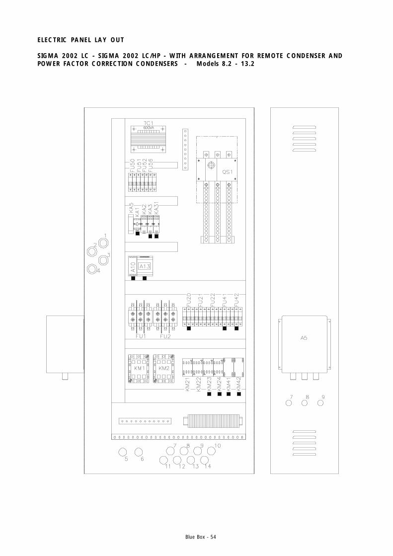
Blue Box - 54
ELECTRIC PANEL LAY OUT
SIGMA 2002 LC - SIGMA 2002 LC/HP - WITH ARRANGEMENT FOR REMOTE CONDENSER ANDPOWER FACTOR CORRECTION CONDENSERS - Models 8.2 - 13.2
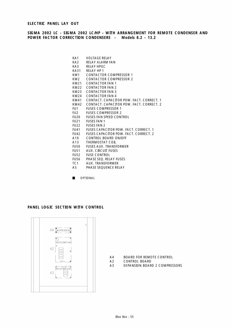
Blue Box - 55
OPTIONAL
KA1 VOLTAGE RELAYKA2 RELAY ALARM FANKA3 RELAY HP/LCKA31 RELAY HP 1KM1 CONTACTOR COMPRESSOR 1KM2 CONTACTOR COMPRESSOR 2KM21 CONTACTOR FAN 1KM22 CONTACTOR FAN 2KM23 CONTACTOR FAN 3KM24 CONTACTOR FAN 4KM41 CONTACT. CAPACITOR POW. FACT. CORRECT. 1KM42 CONTACT. CAPACITOR POW. FACT. CORRECT. 2FU1 FUSES COMPRESSOR 1FU2 FUSES COMPRESSOR 2FU20 FUSES FAN SPEED CONTROLFU21 FUSES FAN 1FU22 FUSES FAN 2FU41 FUSES CAPACITOR POW. FACT. CORRECT. 1FU42 FUSES CAPACITOR POW. FACT. CORRECT. 2A10 CONTROL BOARD ON/OFFA13 THERMOSTAT COILFU50 FUSES AUX. TRANSFORMERFU51 AUX. CIRCUIT FUSESFU52 FUSE CONTROLFU56 PHASE SEQ. RELAY FUSESTC1 AUX. TRANSFORMERA5 PHASE SEQUENCE RELAY
ELECTRIC PANEL LAY OUT
SIGMA 2002 LC - SIGMA 2002 LC/HP - WITH ARRANGEMENT FOR REMOTE CONDENSER ANDPOWER FACTOR CORRECTION CONDENSERS - Models 8.2 - 13.2
PANEL LOGIC SECTION WITH CONTROL
A4 BOARD FOR REMOTE CONTROLA2 CONTROL BOARDA3 EXPANSION BOARD 2 COMPRESSORS
Blue Box - 56
- Verify that the heaters are working correctly. After the warm up period the crankcase must be warm to thetouch and be at a temperature of at least 10 to 15 °C higher than the ambient temperature.
- Check that all hydraulic connections are correctly installed and all indications on the unit labels are observed.
- Check that the hydraulic system has been vented to eliminate any air remaining. Fill the system gradually andopen the vent devices on the higher sections. The installer must provide a correctly sized expansion device.
5. START-UP
5.1 PRELIMINARY CHECKS
- Check that the electrical connections have been made correctly, and that all terminals are tight.
- Check that the voltage on the RST terminals is 400 V ± 5% (or the unit’s rated value, in the event of unitssupplied to run on non-standard power supplies). If the mains voltage is subject to frequent fluctuations, consultour Engineering Department to discuss the necessary protection systems.
- Check that the display shows the gas pressure in the refrigerant circuit (4-compressor models only).
- Inspect the unit for refrigerant leaks using a leak detector if necessary.
- Check that the crankcase heaters are correctly supplied with power.
Significant leakage of R407C refrigerant, in a gaseous state, will alterthe percentages of the remaining mixture with a consequent reduction inperformance.
The heaters must be connected at least 12 hours before starting the unit.The heaters are automatically connected when the main disconnect switchis set to the ON position.
Warning: before starting the unit check that all the enclosure panels arein position and secured with the relative screws.

Models 3.2 - 13.2, controller µchiller
Blue Box - Page 57
Figure 15
Figure 17
Figure 16
6 UNIT WITH mCHILLER MICROPROCESSOR (models from 3.2 to 13.2)
6.1 INTRODUCTION“mCHILLER” is an electronic microprocessor system designed to control all the unit’s functions.The terminal is equipped with five LEDs indicating the operating status of the machine (summer/winter), thecompressor status (On/Off) and indication of the compressors/pump hour counter after the first 100 hours ofoperation. An internal beeper (which can be inhibited by means of a microswitch or a parameter) sounds to warnof machine operating anomalies.
6.1.1 DisplayThe display comprises three digits with automatic display of the decimal point. During normal operation thedisplay shows the value of the evaporator inlet water temperature.“mCHILLER” can be connected to a computer, by means of an optional electronic board, making availableremote supervision and telediagnostic services for complete management, supervision and diagnostics of thesystems from a remote location.
6.1.2 Machine status informationMachine status information is shown by five LEDs on the remote control display (figure 16).
6.1.3 KeypadThe keypad allows machine operating parameters to be programmed. The wall-mounted version features anextended number of keys to facilitate use. The function of each key is illustrated on the following pages.

Models 3.2 - 13.2, controller µchiller
Blue Box - Page 58
Figure 18
Figure 19
Figure 20
6.1.4 Control and display screensMethod of accessing the set-point and main machine control parameters.
Pressing the keys marked with an up or down arrow allows you to scroll through the parameters. The SEL key ispressed again to display the value of the selected parameter, with the facility to edit the value if required usingthe Up or Down keys. The PRG key is pressed to store changed values and to stop the procedure, while pressingthe SEL key returns you to the parameter selection menu. If no keys are pressed, in an interval of 10 seconds,during parameter editing the display starts flashing. If no keys have been pressed within 60 seconds, afteractivating the programming procedure, the controller will return to the temperature display without saving anychanges that have been made. This procedure is useful if it proves unnecessary to alter any parameters.
6.1.5 Muting the BUZZERPress the MUTE key to silence the buzzer if it is currently sounding.
6.1.6 ALARMS resetPressing the Up or Down keys for more than 5 seconds cancels any alarms currently in the memory (manualreset), clear the associated message from the display and deactivate the alarm relay. In wall mounted models thisfunction is obtained by pressing the CLEAR key for 5 seconds.
Parameterscroll keys
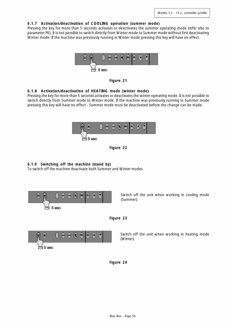
Models 3.2 - 13.2, controller µchiller
Blue Box - Page 59
Figure 21
Figure 22
Figure 23
Figure 24
6.1.7 Activation/deactivation of COOLING operation (summer mode)Pressing the key for more than 5 seconds activates or deactivates the summer operating mode (refer also toparameter P6). It is not possible to switch directly from Winter mode to Summer mode without first deactivatingWinter mode. If the machine was previously running in Winter mode pressing this key will have no effect.
6.1.8 Activation/deactivation of HEATING mode (winter mode)Pressing the key for more than 5 seconds activates or deactivates the winter operating mode. It is not possible toswitch directly from Summer mode to Winter mode. If the machine was previously running in Summer modepressing this key will have no effect - Summer mode must be deactivated before the change can be made.
6.1.9 Switching off the machine (stand by)To switch off the machine deactivate both Summer and Winter modes.
Switch off the unit when working in cooling mode(Summer).
Switch off the unit when working in heating mode(Winter).
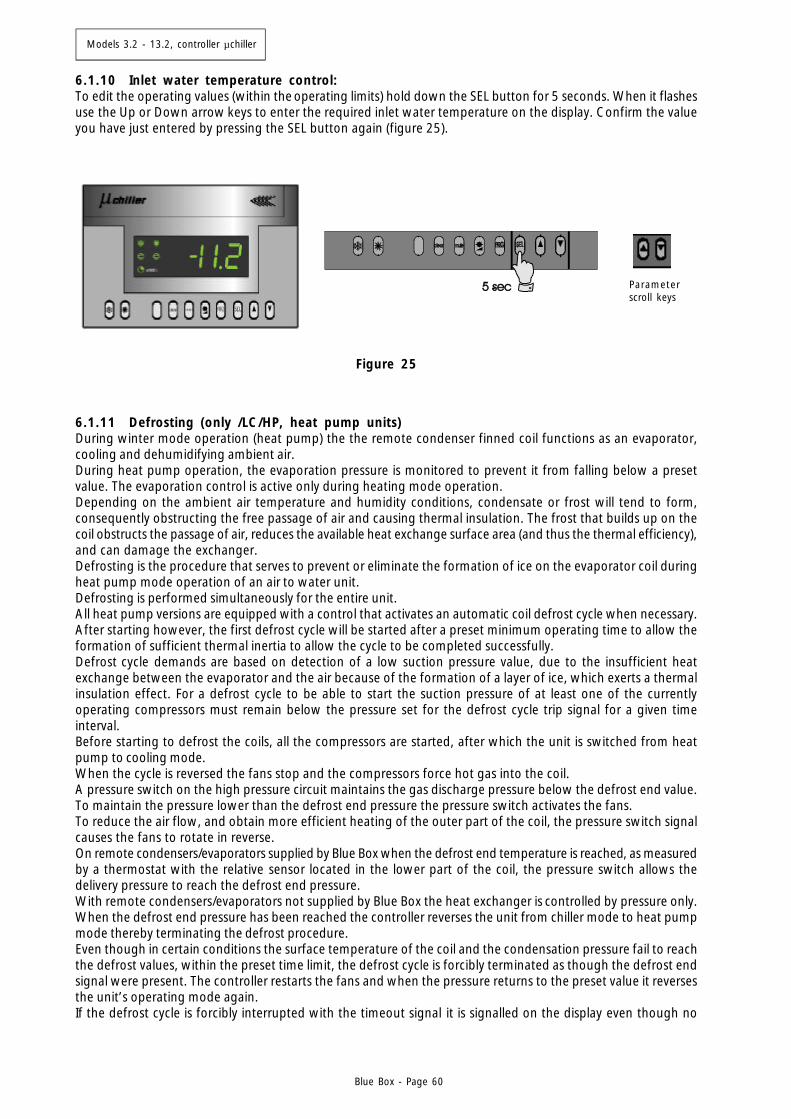
Models 3.2 - 13.2, controller µchiller
Blue Box - Page 60
6.1.11 Defrosting (only /LC/HP, heat pump units)During winter mode operation (heat pump) the the remote condenser finned coil functions as an evaporator,cooling and dehumidifying ambient air.During heat pump operation, the evaporation pressure is monitored to prevent it from falling below a presetvalue. The evaporation control is active only during heating mode operation.Depending on the ambient air temperature and humidity conditions, condensate or frost will tend to form,consequently obstructing the free passage of air and causing thermal insulation. The frost that builds up on thecoil obstructs the passage of air, reduces the available heat exchange surface area (and thus the thermal efficiency),and can damage the exchanger.Defrosting is the procedure that serves to prevent or eliminate the formation of ice on the evaporator coil duringheat pump mode operation of an air to water unit.Defrosting is performed simultaneously for the entire unit.All heat pump versions are equipped with a control that activates an automatic coil defrost cycle when necessary.After starting however, the first defrost cycle will be started after a preset minimum operating time to allow theformation of sufficient thermal inertia to allow the cycle to be completed successfully.Defrost cycle demands are based on detection of a low suction pressure value, due to the insufficient heatexchange between the evaporator and the air because of the formation of a layer of ice, which exerts a thermalinsulation effect. For a defrost cycle to be able to start the suction pressure of at least one of the currentlyoperating compressors must remain below the pressure set for the defrost cycle trip signal for a given timeinterval.Before starting to defrost the coils, all the compressors are started, after which the unit is switched from heatpump to cooling mode.When the cycle is reversed the fans stop and the compressors force hot gas into the coil.A pressure switch on the high pressure circuit maintains the gas discharge pressure below the defrost end value.To maintain the pressure lower than the defrost end pressure the pressure switch activates the fans.To reduce the air flow, and obtain more efficient heating of the outer part of the coil, the pressure switch signalcauses the fans to rotate in reverse.On remote condensers/evaporators supplied by Blue Box when the defrost end temperature is reached, as measuredby a thermostat with the relative sensor located in the lower part of the coil, the pressure switch allows thedelivery pressure to reach the defrost end pressure.With remote condensers/evaporators not supplied by Blue Box the heat exchanger is controlled by pressure only.When the defrost end pressure has been reached the controller reverses the unit from chiller mode to heat pumpmode thereby terminating the defrost procedure.Even though in certain conditions the surface temperature of the coil and the condensation pressure fail to reachthe defrost values, within the preset time limit, the defrost cycle is forcibly terminated as though the defrost endsignal were present. The controller restarts the fans and when the pressure returns to the preset value it reversesthe unit’s operating mode again.If the defrost cycle is forcibly interrupted with the timeout signal it is signalled on the display even though no
Parameterscroll keys
Figure 25
6.1.10 Inlet water temperature control:To edit the operating values (within the operating limits) hold down the SEL button for 5 seconds. When it flashesuse the Up or Down arrow keys to enter the required inlet water temperature on the display. Confirm the valueyou have just entered by pressing the SEL button again (figure 25).
Models 3.2 - 13.2, controller µchiller
Blue Box - Page 61
During idle periods do not disconnect the unit from the power supply (thecompressor crankcase heaters must remain switched on in these intervals).Disconnect the unit from the power supply only in the event of prolongeddisuse (e.g. seasonal shutdowns). For temporary shutdown of the unitrefer to the guide lines given in paragraph 6.3.1.
If the unit fails to start:do not change internal electrical connections on penalty of immedia-te invalidation of the warranty.
Warning: The operating mode changeover should only be seasonal.Frequent changeover from summer to winter operating mode and vice-versa could cause damage to the compressors.
controller functions are activated.The defrost timeout alarm is automatically cleared from the active alarms menus when a defrost cycle terminatesnormally because the defrost end pressure has been reached. In any event, the alarms historical file will containa record of all defrost cycles that were terminated forcibly due to a timeout intervention.Consecutive defrost cycles must be at least 30 minutes apart. If a forced defrost signal persists inform the Serviceorganisation.
Electronic components of the microprocessor may be damaged attemperatures below - 20 °C.
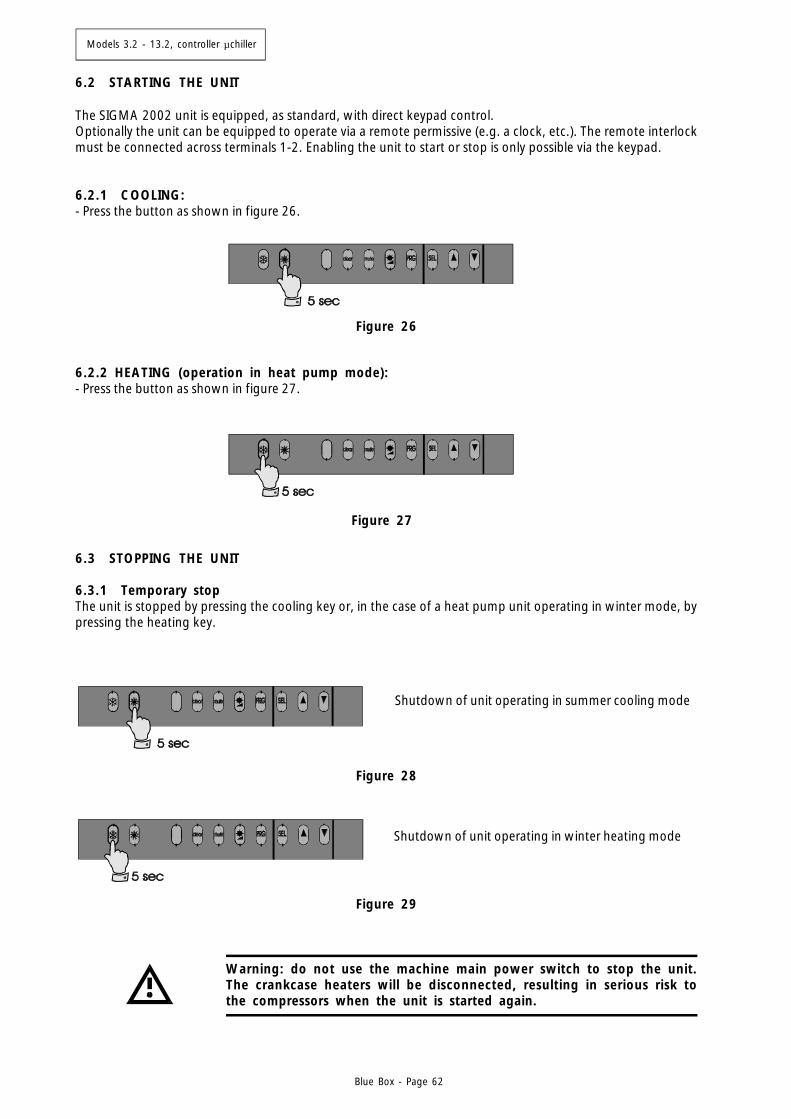
Models 3.2 - 13.2, controller µchiller
Blue Box - Page 62
Figure 26
Figure 27
Figure 29
Figure 28
6.2 STARTING THE UNIT
The SIGMA 2002 unit is equipped, as standard, with direct keypad control.Optionally the unit can be equipped to operate via a remote permissive (e.g. a clock, etc.). The remote interlockmust be connected across terminals 1-2. Enabling the unit to start or stop is only possible via the keypad.
6.2.1 COOLING:- Press the button as shown in figure 26.
6.2.2 HEATING (operation in heat pump mode):- Press the button as shown in figure 27.
6.3 STOPPING THE UNIT
6.3.1 Temporary stopThe unit is stopped by pressing the cooling key or, in the case of a heat pump unit operating in winter mode, bypressing the heating key.
Shutdown of unit operating in summer cooling mode
Shutdown of unit operating in winter heating mode
Warning: do not use the machine main power switch to stop the unit.The crankcase heaters will be disconnected, resulting in serious risk tothe compressors when the unit is started again.

Models 3.2 - 13.2, controller µchiller
Blue Box - Page 63
6.3.2 Seasonal stop:- Disconnect the power supply- Drain the system circuit (unless it contains a water/glycol solution)- When the unit is to be restarted repeat the initial start-up procedure
Warning: do not use the machine main power switch to stop the unit:this switch must be used to disconnect the electrical supply when nocurrent is flowing on the circuit, i.e. only when the unit is in OFF status.Note also that if power is disconnected from the unit the crankcaseheaters will be switched off with the resulting risk of compressor damageat the time of restarting.
6.4 EMERGENCY STOP
Emergency stops are obtained by turning the red colour main disconnect switch on the electrical panel to position0.
7. TROUBLESHOOTING
The following pages contain a list of the most common causes that can result in the shutdown or anomalousoperation of the chiller. Faults are arranged in accordance with easily identifiable symptoms.
In relation to possible corrective action pay maximum attention to theoperat ions you intend to perform as overconfidence coupled withinsufficient attention due to lack of expertise can lead to serious accidents.We therefore recommend that Blue Box or other skilled HVAC engineersare contacted to identify and correct the problem.
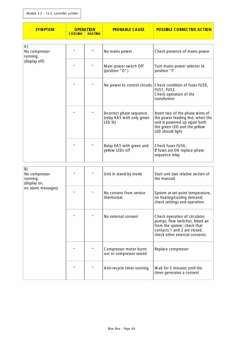
Models 3.2 - 13.2, controller µchiller
Blue Box - Page 64
SYMPTOM
OPERATION
PROBABLE CAUSE
POSSIBLE CORRECTIVE ACTION
COOLING
HEATING
A) No compressor ⊗ ⊗ No mains power Check presence of mains power running. (display off) ⊗ ⊗ Main power switch Off
(position "O") Turn mains power selector to position "I"
⊗ ⊗ No power to control circuits Check condition of fuses FU50,
FU51, FU52. Check operation of the transformer
⊗ ⊗ Incorrect phase sequence
(relay KA5 with only green LED lit)
Invert two of the phase wires of the power feeding line; when the unit is powered up again both the green LED and the yellow LED should light
⊗ ⊗ Relay KA5 with green and
yellow LEDs off Check fuses FU56; If fuses are OK replace phase sequence relay
B) No compressor running.
⊗ ⊗ Unit in stand-by mode Start unit (see relative section of the manual)
(display on, no alarm messages) ⊗ ⊗ No consent from service
thermostat System at set-point temperature, no heating/cooling demand; check settings and operation.
⊗ ⊗ No external consent Check operation of circulator
pumps, flow switches, bleed air from the system; check that contacts 1 and 2 are closed, check other external consents.
⊗ ⊗ Compressor motor burnt
out or compressor seized Replace compressor
⊗ ⊗ Anti-recycle timer running Wait for 5 minutes until the
timer generates a consent
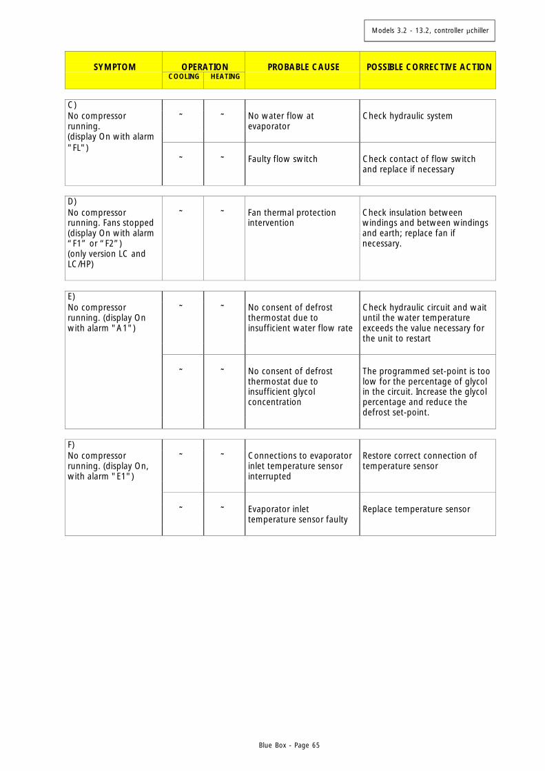
Models 3.2 - 13.2, controller µchiller
Blue Box - Page 65
SYMPTOM
OPERATION
PROBABLE CAUSE
POSSIBLE CORRECTIVE ACTION
COOLING
HEATING
C) No compressor running.
⊗ ⊗ No water flow at evaporator
Check hydraulic system
(display On with alarm "FL") ⊗ ⊗ Faulty flow switch Check contact of flow switch
and replace if necessary D) No compressor running. Fans stopped (display On with alarm “F1” or “F2”) (only version LC and LC/HP)
⊗ ⊗ Fan thermal protection intervention
Check insulation between windings and between windings and earth; replace fan if necessary.
E) No compressor running. (display On with alarm "A1")
⊗ ⊗ No consent of defrost thermostat due to insufficient water flow rate
Check hydraulic circuit and wait until the water temperature exceeds the value necessary for the unit to restart
⊗ ⊗ No consent of defrost
thermostat due to insufficient glycol concentration
The programmed set-point is too low for the percentage of glycol in the circuit. Increase the glycol percentage and reduce the defrost set-point.
F) No compressor running. (display On, with alarm "E1")
⊗ ⊗ Connections to evaporator inlet temperature sensor interrupted
Restore correct connection of temperature sensor
⊗ ⊗ Evaporator inlet
temperature sensor faulty Replace temperature sensor
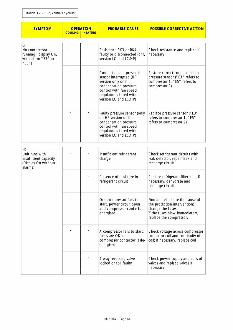
Models 3.2 - 13.2, controller µchiller
Blue Box - Page 66
SYMPTOM
OPERATION
PROBABLE CAUSE
POSSIBLE CORRECTIVE ACTION
COOLING
HEATING
G) No compressor running. (display On, with alarm "E3" or
⊗ ⊗ Resistance RK3 or RK4 faulty or disconnected (only version LC and LC/HP)
Check resistance and replace if necessary
"E5") ⊗ ⊗ Connections to pressure
sensor interrupted (HP version only or if condensation pressure control with fan speed regulator is fitted with version LC and LC/HP)
Restore correct connections to pressure sensor ("E3" refers to compressor 1, "E5" refers to compressor 2)
⊗ ⊗ Faulty pressure sensor (only
on HP version or if condensation pressure control with fan speed regulator is fitted with version LC and LC/HP)
Replace pressure sensor ("E3" refers to compressor 1, "E5" refers to compressor 2)
H) Unit runs with insufficient capacity (Display On without
⊗ ⊗ Insufficient refrigerant charge
Check refrigerant circuits with leak detector, repair leak and recharge circuit
alarms) ⊗ ⊗ Presence of moisture in
refrigerant circuit Replace refrigerant filter and, if necessary, dehydrate and recharge circuit
⊗ ⊗ One compressor fails to
start, power circuit open and compressor contactor energised
Find and eliminate the cause of the protection intervention; change the fuses. If the fuses blow immediately, replace the compressor.
⊗ ⊗ A compressor fails to start,
fuses are OK and compressor contactor is de-energised
Check voltage across compressor contactor coil and continuity of coil; if necessary, replace coil
⊗ 4-way reversing valve
locked or coil faulty Check power supply and coils of valves and replace valves if necessary
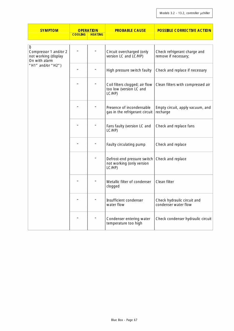
Models 3.2 - 13.2, controller µchiller
Blue Box - Page 67
SYMPTOM
OPERATION
PROBABLE CAUSE
POSSIBLE CORRECTIVE ACTION
COOLING
HEATING
I) Compressor 1 and/or 2 not working (display
⊗ ⊗ Circuit overcharged (only version LC and LC/HP)
Check refrigerant charge and remove if necessary;
On with alarm “H1” and/or “H2”) ⊗ ⊗ High pressure switch faulty Check and replace if necessary ⊗ ⊗ Coil filters clogged; air flow
too low (version LC and LC/HP)
Clean filters with compressed air
⊗ ⊗ Presence of incondensable
gas in the refrigerant circuit Empty circuit, apply vacuum, and recharge
⊗ ⊗ Fans faulty (version LC and
LC/HP) Check and replace fans
⊗ ⊗ Faulty circulating pump Check and replace ⊗ Defrost-end pressure switch
not working (only version LC/HP)
Check and replace
⊗ ⊗ Metallic filter of condenser
clogged Clean filter
⊗ ⊗ Insufficient condenser
water flow Check hydraulic circuit and condenser water flow
⊗ ⊗ Condenser entering water
temperature too high Check condenser hydraulic circuit
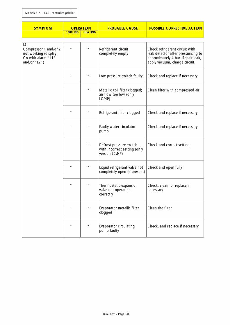
Models 3.2 - 13.2, controller µchiller
Blue Box - Page 68
SYMPTOM
OPERATION
PROBABLE CAUSE
POSSIBLE CORRECTIVE ACTION
COOLING
HEATING
L) Compressor 1 and/or 2 not working (display On with alarm “L1” and/or “L2”)
⊗ ⊗ Refrigerant circuit completely empty
Check refrigerant circuit with leak detector after pressurising to approximately 4 bar. Repair leak, apply vacuum, charge circuit.
⊗ ⊗ Low pressure switch faulty Check and replace if necessary ⊗ Metallic coil filter clogged;
air flow too low (only LC/HP)
Clean filter with compressed air
⊗ ⊗ Refrigerant filter clogged Check and replace if necessary ⊗ ⊗ Faulty water circulator
pump Check and replace if necessary
⊗ Defrost pressure switch
with incorrect setting (only version LC/HP)
Check and correct setting
⊗ ⊗ Liquid refrigerant valve not
completely open (if present) Check and open fully
⊗ ⊗ Thermostatic expansion
valve not operating correctly
Check, clean, or replace if necessary
⊗ ⊗ Evaporator metallic filter
clogged Clean the filter
⊗ ⊗ Evaporator circulating
pump faulty Check, and replace if necessary
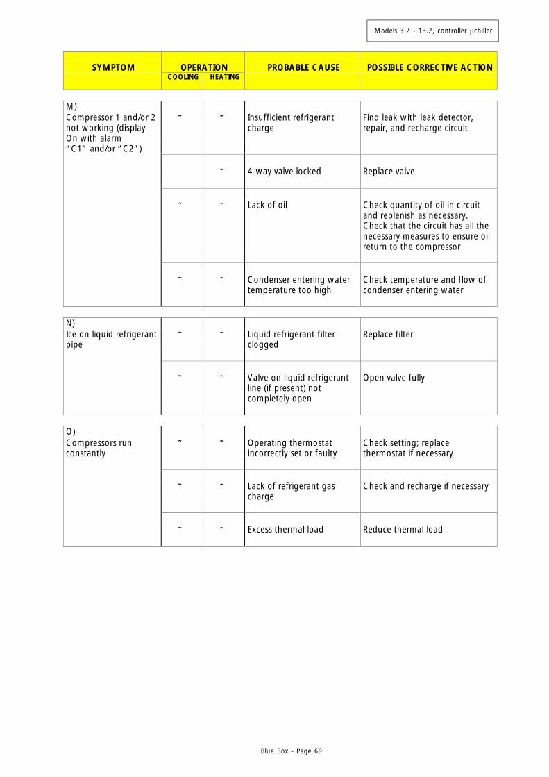
Models 3.2 - 13.2, controller µchiller
Blue Box - Page 69
SYMPTOM
OPERATION
PROBABLE CAUSE
POSSIBLE CORRECTIVE ACTION
COOLING
HEATING
M) Compressor 1 and/or 2 not working (display On with alarm
⊗ ⊗ Insufficient refrigerant charge
Find leak with leak detector, repair, and recharge circuit
“C1” and/or “C2”) ⊗ 4-way valve locked Replace valve ⊗ ⊗ Lack of oil Check quantity of oil in circuit
and replenish as necessary. Check that the circuit has all the necessary measures to ensure oil return to the compressor
⊗ ⊗ Condenser entering water
temperature too high Check temperature and flow of condenser entering water
N) Ice on liquid refrigerant pipe
⊗ ⊗ Liquid refrigerant filter clogged
Replace filter
⊗ ⊗ Valve on liquid refrigerant
line (if present) not completely open
Open valve fully
O) Compressors run constantly
⊗ ⊗ Operating thermostat incorrectly set or faulty
Check setting; replace thermostat if necessary
⊗ ⊗ Lack of refrigerant gas
charge Check and recharge if necessary
⊗ ⊗ Excess thermal load Reduce thermal load
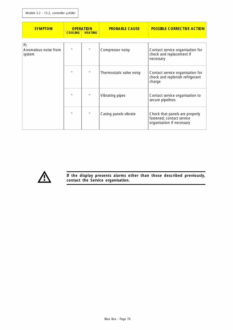
Models 3.2 - 13.2, controller µchiller
Blue Box - Page 70
If the display presents alarms other than those described previously,contact the Service organisation.
SYMPTOM
OPERATION
PROBABLE CAUSE
POSSIBLE CORRECTIVE ACTION
COOLING
HEATING
P) Anomalous noise from system
⊗ ⊗ Compressor noisy Contact service organisation for check and replacement if necessary
⊗ ⊗ Thermostatic valve noisy Contact service organisation for
check and replenish refrigerant charge
⊗ ⊗ Vibrating pipes Contact service organisation to
secure pipelines ⊗ ⊗ Casing panels vibrate Check that panels are properly
fastened; contact service organisation if necessary
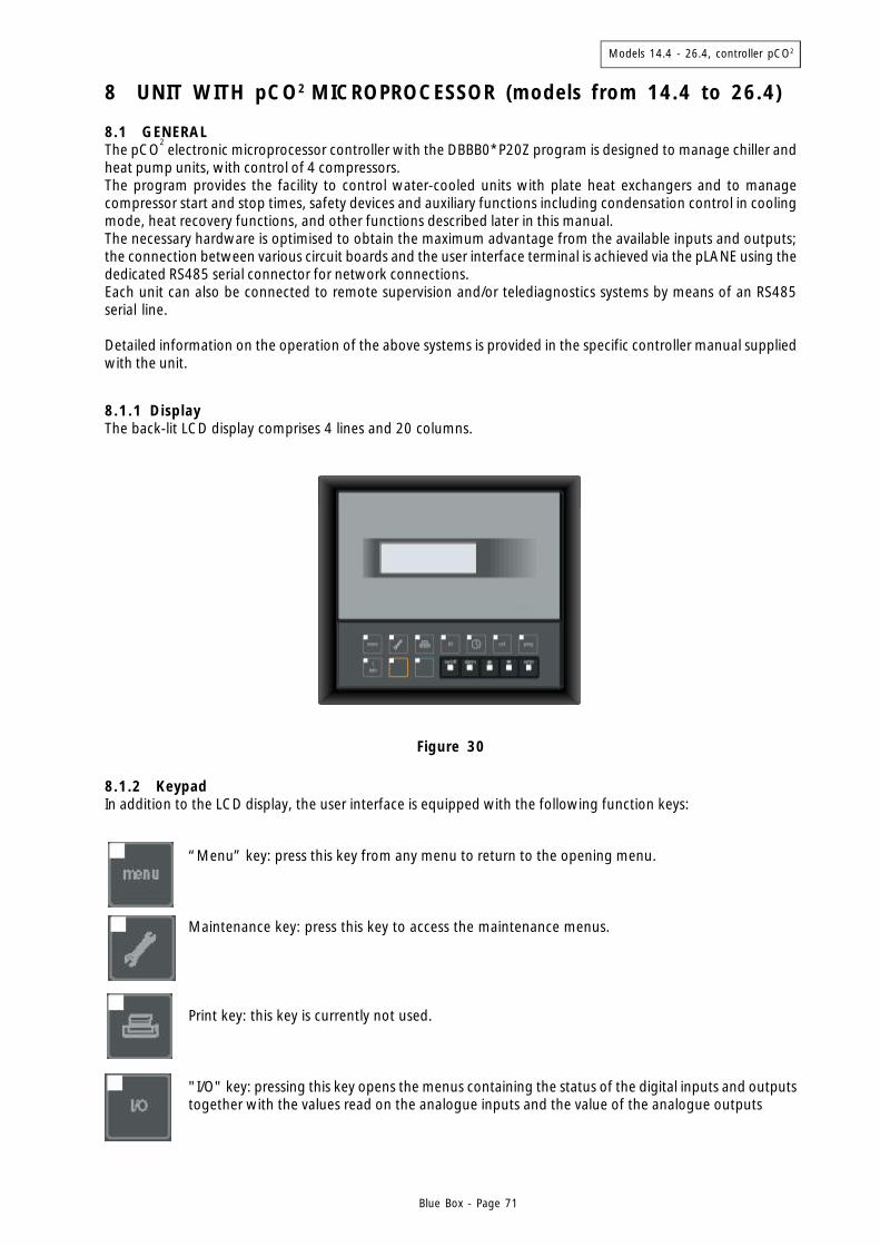
Models 14.4 - 26.4, controller pCO2
Blue Box - Page 71
8 UNIT WITH pCO2 MICROPROCESSOR (models from 14.4 to 26.4)
8.1 GENERALThe pCO
2 electronic microprocessor controller with the DBBB0*P20Z program is designed to manage chiller and
heat pump units, with control of 4 compressors.The program provides the facility to control water-cooled units with plate heat exchangers and to managecompressor start and stop times, safety devices and auxiliary functions including condensation control in coolingmode, heat recovery functions, and other functions described later in this manual.The necessary hardware is optimised to obtain the maximum advantage from the available inputs and outputs;the connection between various circuit boards and the user interface terminal is achieved via the pLANE using thededicated RS485 serial connector for network connections.Each unit can also be connected to remote supervision and/or telediagnostics systems by means of an RS485serial line.
Detailed information on the operation of the above systems is provided in the specific controller manual suppliedwith the unit.
8.1.1 DisplayThe back-lit LCD display comprises 4 lines and 20 columns.
Figure 30
8.1.2 KeypadIn addition to the LCD display, the user interface is equipped with the following function keys:
“Menu” key: press this key from any menu to return to the opening menu.
Maintenance key: press this key to access the maintenance menus.
Print key: this key is currently not used.
"I/O" key: pressing this key opens the menus containing the status of the digital inputs and outputstogether with the values read on the analogue inputs and the value of the analogue outputs
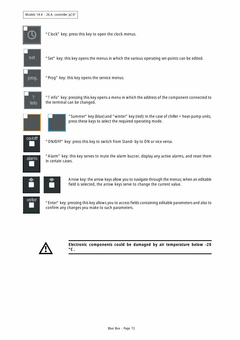
Models 14.4 - 26.4, controller pCO2
Blue Box - Page 72
Electronic components could be damaged by air temperature below -20°C.
“Enter” key: pressing this key allows you to access fields containing editable parameters and also toconfirm any changes you make to such parameters.
"? info" key: pressing this key opens a menu in which the address of the component connected tothe terminal can be changed.
"Summer" key (blue) and "winter" key (red): in the case of chiller + heat-pump units,press these keys to select the required operating mode.
“ON/OFF” key: press this key to switch from Stand- by to ON or vice versa.
“Alarm” key: this key serves to mute the alarm buzzer, display any active alarms, and reset themin certain cases.
Arrow key: the arrow keys allow you to navigate through the menus; when an editablefield is selected, the arrow keys serve to change the current value.
“Clock” key: press this key to open the clock menus.
“Set” key: this key opens the menus in which the various operating set-points can be edited.
“Prog” key: this key opens the service menus.
Models 14.4 - 26.4, controller pCO2
Blue Box - Page 73
8.2 OPERATING DESCRIPTION
8.2.1 Introduction
The microprocessor control regulates the water temperature of the evaporator maintaining it at the set-pointvalue acting on the compressors management.The control manages all the components of the chiller, the alarms and “ancillary” functions.
Almost all the parameters referred to below (set-points, differentials, calibration, delays...) can be programmedby means of the various menus. Refer to the specific manual for the pCO2 controller.
8.2.2 Unit in stand-by mode
The unit is in stand-by mode when it is correctly supplied with power but not actually enabled to operate.In this condition the display shows the values of the various machine parameters, but the operation of thecompressor is not inhibited.Power-on is obtained by pressing the “ON-OFF” button of the microprocessor control or via an external interlock.
8.2.3 Enabling the unit
Start-up of the unit from stand-by mode can be achieved after closing the external enabling contact, by pressingthe "ON/OFF" button, or by means of a signal on the serial line.Activation of the controller outputs that manage the various sections of the chiller is executed in strict compliancewith the operating times. If the "ON" button is pressed before the external interlocks are closed, the displayindicates which of the external interlocks is not yet enabled.Operation of the pump has priority to the compressors, which can start only after the evaporator and condenserpumps are running.
8.2.4 Pumps management
The microprocessor controller does not manage the operation of chilled water and condenser pumps.When the unit is switched from normal operation to stand-by, due to the opening of an external interlock, theactive pump must be stopped with a delay following the stopping of the last active compressor, to benefit fromthe thermal inertia of the system.
8.2.5 Compressor start-up
The controller allows the compressors to be started if the flow switch input is closed within the compressor start-up delay time interval. If the flow switch input opens, after the compressor has started, the trip is retarded if itoccurs within the time programmed for the compressor stop.If the unit trips due to the opening of the flow switch input, the relative alarm is displayed.Starting and stopping of the compressors and capacity step control is managed by the controller in accordancewith the building cooling demands.
8.2.6 Chiller mode operation
In chiller operation, the controller lowers the water temperature value, maintaining it as close as possible to theprogrammed set-point.In the standard version, in which the control acts on the evaporator entering water, the management of compressoroperation and capacity steps is linked to the difference between the entering water temperature and the programmedset-point.
Models 14.4 - 26.4, controller pCO2
Blue Box - Page 74
8.2.8 Evaporator low temperature chilled water protection
If the evaporator leaving water temperature is lower than the limit value programmed in the low temperaturechilled water protection set-point, the controller will stop all the compressors and activate the low temperaturewater alarm.This alarm must be reset manually and the compressor restarted only when the evaporator leaving water tempe-rature is equal to or higher than the alarm trip value, increased by the low temperature water differential.The low temperature water alarm can only appear when the unit is switched on (in stand-by conditions the freezealarm is not operational).
8.2.9 Evaporator anti-freeze protection electric heater (optional)
In conditions that lead to tripping the freeze alarm, the controller energises the heater.The heater remains powered for the entire time that the conditions for the freeze alarm continue.Unlike the low water temperature alarm, which is enabled only when the unit is powered on, the anti-freezeheater can be energised when the machine is on stand-by.
8.2.10 Compressor operation
When the unit is running correctly and no general alarms are present, the microprocessor controller starts thecompressors in accordance with the water temperature reading.Compressor starts are staggered in accordance with preset delay intervals, thus avoiding excess input currentsurges.Before starting a compressor, the microprocessor checks the value of the delivery pressure by means of therelevant transducer, the status of the high pressure switch and the compressor motor windings temperature bychecking the thermal protection.
When the compressor has been started, tripping of any of the safety devices will cause the compressor to stopimmediately and an alarm will be displayed.While the compressor is running, discharge pressure and suction pressure are monitored constantly by means ofthe relevant sensors.
On unit start-up the first compressor is started with a delay, set on the microprocessor controller, after the start ofthe hydraulic system circulating pump.Once started, each compressor must run for a minimum operating period, unless a critical alarm should trip in themeantime.The critical alarms which can stop the compressor during the minimum operating time are the high pressurealarm and the compressor thermal cut-out alarm. Once stopped each compressor can be restarted only after aminimum idle time or after a minimum time interval between two consecutive starts has elapsed.The consecutive starting of two compressors or the consecutive starting of one compressor, is executed withminimum delay intervals equal to the capacity step activation time.Stopping compressors is also performed with a minimum programmed delay interval.
8.2.7 Heat pump mode operation
In heat pump operation, the controller increases the water temperature value, maintaining it as close as possibleto the programmed set-point.Management of compressor operation is performed in the same way as already illustrated for chiller modeoperation.
Models 14.4 - 26.4, controller pCO2
Blue Box - Page 75
8.2.13 Changeover from chiller to heat pump and vice versa
The changeover from chiller to heat pump and back can be performed at any time, either by means of anexternal signal on a digital input, from the keypad, or via the serial line. The operating mode changeover must beonly seasonal and only with the unit off.After a mode changeover, the controller re-starts the unit in the new mode with a factory set minimum delaytime.The unit operates with temperature control on the inlet to which has been inactive for the longest time. the unit(or return from the system).
8.2.14 Desuperheater (Option)
The desuperheater recovers part of the total power to be dissipated into the condenser to produce hot water(water inlet temperature 40 °C, water leaving temperature 45 °C at design conditions). This is energy efficientand therefore has an economic benefit. Each refrigerant circuit is supplied with a shell and tube desuperheaterpositioned in series to the main condenser.See paragraph 4.6 for the hydraulic diagram.
8.2.11 Compressor management
Start-up of the compressors is automatic when the reference water temperature changes with respect to theprogrammed set-point.Normally the reference water temperature is the value detected at the inlet to the chiller unit.
Balancing of duty hours over all the compressors in the unit is performed by selecting the rotation of starts.With the rotation function of starts active, the first compressor to start is the first one that previously stopped. Alsothe first compressor to start will be the one with the most operating hours.
8.2.12 High and low pressure alarms
Discharge pressure (high pressure) and suction pressure (low pressure) are managed by the microprocessor controllerthrough the relevant sensors.When a compressor is running, the controller checks that:- Discharge pressure is always lower than the safety value set for cooling or heating mode operation. If the values
are exceeded, the controller immediately stops the compressor and displays a high pressure alarm. The highpressure alarm can be reset manually on the controller only when the pressure detected by the dischargepressure sensor is lower than the value that caused the alarm to trip, less the differential value.
- The suction pressure is always higher than the safety value set for operation in cooling or heating mode. If thevalue read by the suction pressure sensor is lower than the limits set for the relative operating conditions, thecontroller will stop the compressor and generate a low pressure alarm. The low pressure alarm is not instantaneous,but operates after a preset delay interval, both in the starting phase and during the normal running of themachine. The low pressure alarm can be reset automatically or manually, depending on the relative parametersetting. In all cases the low pressure alarm can only be reset when the pressure detected by the suction sensoris higher than the value that caused the alarm to trip, plus the differential value. It is possible to program thenumber of permissible consecutive compressor starts before the unit shuts down in safety status.
8.2.15 Total heat recovery (only SIGMA 2002/DC)
The goal of total heat recovery is to recover 100% of the heat energy that would be rejected in the process toachieve energy efficiency and an economic benefit.SIGMA 2002/DC units have a 100% heat recovery condenser on each refrigeration circuit for the production ofhot water (water inlet temperature 40 °C, water leaving temperature 45 °C at design conditions). The heatrecovery condenser is positioned between the compressor and the main condenser (see refrigerant diagram). Theheat recovery and condenser water circuits are completely independent to allow maximum working flexibility inthe use of the water which passes through the heat recovery condenser. With the heat recovery off, (when nowater is flowing through the recovery heat exchanger) the unit operates as a standard chiller.
Models 14.4 - 26.4, controller pCO2
Blue Box - Page 76
8.2.18 Defrost (heat pumps units /LC/HP)
During winter mode operation (heat pump) the the remote condenser finned coil functions as an evaporator,cooling and dehumidifying ambient air.During heat pump operation, the evaporation pressure is monitored to prevent it from falling below a presetvalue. The evaporation control is active only during heating mode operation.Depending on the ambient air temperature and humidity conditions, condensate or frost will tend to form,consequently obstructing the free passage of air and causing thermal insulation. The frost that builds up on thecoil obstructs the passage of air, reduces the available heat exchange surface area (and thus the thermal efficiency),and can damage the exchanger.Defrosting is the procedure that serves to prevent or eliminate the formation of ice on the evaporator coil duringheat pump mode operation of an air to water unit.Defrosting is performed simultaneously for the entire unit.All heat pump versions are equipped with a control that activates an automatic coil defrost cycle when necessary.After starting however, the first defrost cycle will be started after a preset minimum operating time to allow theformation of sufficient thermal inertia to allow the cycle to be completed successfully.Defrost cycle demands are based on detection of a low suction pressure value, due to the insufficient heatexchange between the evaporator and the air because of the formation of a layer of ice, which exerts a thermalinsulation effect. For a defrost cycle to be able to start the suction pressure of at least one of the currentlyoperating compressors must remain below the pressure set for the defrost cycle trip signal for a given timeinterval.Before starting to defrost the coils, all the compressors are started, after which the unit is switched from heatpump to cooling mode.When the cycle is reversed the fans stop and the compressors force hot gas into the coil.A pressure switch on the high pressure circuit maintains the gas discharge pressure below the defrost end value.To maintain the pressure lower than the defrost end pressure the pressure switch activates the fans.To reduce the air flow, and obtain more efficient heating of the outer part of the coil, the pressure switch signalcauses the fans to rotate in reverse.On remote condensers/evaporators supplied by Blue Box when the defrost end temperature is reached, as measuredby a thermostat with the relative sensor located in the lower part of the coil, the pressure switch allows thedelivery pressure to reach the defrost end pressure.With remote condensers/evaporators not supplied by Blue Box the heat exchanger is controlled by pressure only.When the defrost end pressure has been reached the controller reverses the unit from chiller mode to heat pumpmode thereby terminating the defrost procedure.Even though in certain conditions the surface temperature of the coil and the condensation pressure fail to reachthe defrost values, within the preset time limit, the defrost cycle is forcibly terminated as though the defrost endsignal were present. The controller restarts the fans and when the pressure returns to the preset value it reversesthe unit's operating mode again.If the defrost cycle is forcibly interrupted with the timeout signal it is signalled on the display even though no
8.2.16 Dual set-point (option)
With double thermostatic valves and solenoid valves that are automatically switched according to the requiredexpansion temperature. Two set-point values can be programmed on the microprocessor controller via the keypador a digital input. Switching of the thermostatic valves is always automatic, in accordance with the water tempe-rature. The valves are sized on the basis of the temperature values specified at the time of the order. Themachine operating limits shown in the catalogue are not affected. If the hydraulic circuit contains glycol insufficient quantities to eliminate the risk of freezing, the lower limit is extended to a minimum of -5 °C leavingwater temperature.
8.2.17 Leaving water temperature control (option)
With leaving chilled water temperature control a reference sensor must be installed on the evaporator outlet.The unit's capacity steps are activated / deactivated with delay intervals in relation to a dead zone. When theleaving water temperature is higher than the programmed set-point compressors start is enabled.
Models 14.4 - 26.4, controller pCO2
Blue Box - Page 77
controller functions are activated.The defrost timeout alarm is automatically cleared from the active alarms menus when a defrost cycle terminatesnormally because the defrost end pressure has been reached. In any event, the alarms historical file will containa record of all defrost cycles that were terminated forcibly due to a timeout intervention.Consecutive defrost cycles must be at least 30 minutes apart. If a forced defrost signal persists inform the Serviceorganisation.
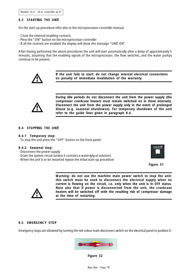
Models 14.4 - 26.4, controller pCO2
Blue Box - Page 78
During idle periods do not disconnect the unit from the power supply (thecompressor crankcase heaters must remain switched on in these intervals).Disconnect the unit from the power supply only in the event of prolongeddisuse (e.g. seasonal shutdowns). For temporary shutdown of the unitrefer to the guide lines given in paragraph 8.4.
Figure 31
Figure 32
8.3 STARTING THE UNIT
For the start-up procedure refer also to the microprocessor controller manual.
- Close the external enabling contacts- Press the "ON" button on the microprocessor controller- If all the controls are enabled the display will show the message "UNIT ON"
After having performed the above procedures the unit will start automatically after a delay of approximately 5minutes, assuming that the enabling signals of the microprocessor, the flow switches, and the water pumpscontinue to be present.
If the unit fails to start: do not change internal electrical connectionson penalty of immediate invalidation of the warranty.
8.4 STOPPING THE UNIT
8.4.1 Temporary stop:- To stop the unit press the "OFF" button on the front panel.
8.4.2 Seasonal stop:- Disconnect the power supply- Drain the system circuit (unless it contains a water/glycol solution)- When the unit is to be restarted repeat the initial start-up procedure
Warning: do not use the machine main power switch to stop the unit:this switch must be used to disconnect the electrical supply when nocurrent is flowing on the circuit, i.e. only when the unit is in OFF status.Note also that if power is disconnected from the unit, the crankcaseheaters will be switched off with the resulting risk of compressor damageat the time of restarting.
8.5 EMERGENCY STOP
Emergency stops are obtained by turning the red colour main disconnect switch on the electrical panel to position 0.
Models 14.4 - 26.4, controller pCO2
Blue Box - Page 79
9. TROUBLESHOOTING
The following pages contain a list of the most common causes that can result in the shutdown or anomalousoperation of the chiller. Faults are arranged in accordance with easily identifiable symptoms.
In relation to possible corrective action, adopt the maximum attention inthe operations you intend to perform as overconfidence coupled withinsufficient attention due to lack of expertise can lead to serious accidents.We therefore recommend that Blue Box or other skilled HVAC engineersare contacted to identify and correct the problem.
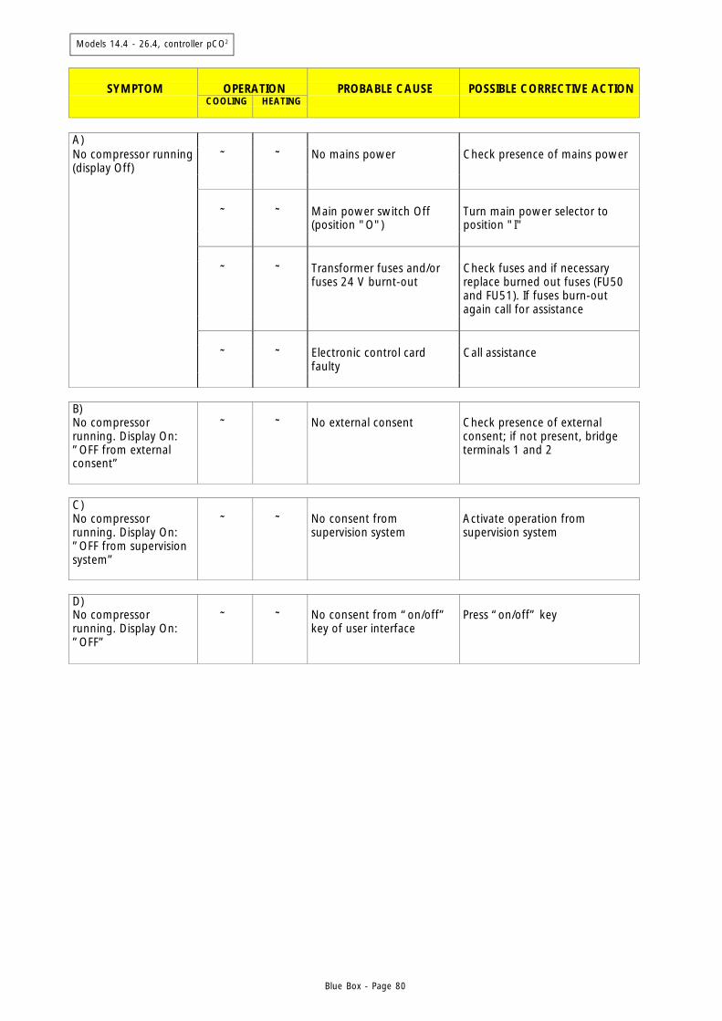
Models 14.4 - 26.4, controller pCO2
Blue Box - Page 80
SYMPTOM
OPERATION
PROBABLE CAUSE
POSSIBLE CORRECTIVE ACTION
COOLING
HEATING
A) No compressor running (display Off)
⊗ ⊗ No mains power Check presence of mains power
⊗ ⊗ Main power switch Off
(position "O") Turn main power selector to position "I"
⊗ ⊗ Transformer fuses and/or
fuses 24 V burnt-out Check fuses and if necessary replace burned out fuses (FU50 and FU51). If fuses burn-out again call for assistance
⊗ ⊗ Electronic control card
faulty Call assistance
B) No compressor running. Display On: ”OFF from external consent”
⊗ ⊗ No external consent Check presence of external consent; if not present, bridge terminals 1 and 2
C) No compressor running. Display On: ”OFF from supervision system”
⊗ ⊗ No consent from supervision system
Activate operation from supervision system
D) No compressor running. Display On: ”OFF”
⊗ ⊗ No consent from “on/off” key of user interface
Press “on/off” key
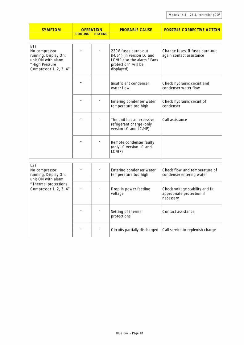
Models 14.4 - 26.4, controller pCO2
Blue Box - Page 81
SYMPTOM
OPERATION
PROBABLE CAUSE
POSSIBLE CORRECTIVE ACTION
COOLING
HEATING
E1) No compressor running. Display On: unit ON with alarm “High Pressure Compressor 1, 2, 3, 4”
⊗ ⊗ 220V fuses burnt-out (FU51) (in version LC and LC/HP also the alarm “Fans protection” will be displayed)
Change fuses. If fuses burn-out again contact assistance
⊗ Insufficient condenser
water flow Check hydraulic circuit and condenser water flow
⊗ ⊗ Entering condenser water
temperature too high Check hydraulic circuit of condenser
⊗ ⊗ The unit has an excessive
refrigerant charge (only version LC and LC/HP)
Call assistance
⊗ ⊗ Remote condenser faulty
(only LC version LC and LC/HP)
E2) No compressor running. Display On:
⊗ ⊗ Entering condenser water temperature too high
Check flow and temperature of condenser entering water
unit ON with alarm “Thermal protections Compressor 1, 2, 3, 4” ⊗ ⊗ Drop in power feeding
voltage Check voltage stability and fit appropriate protection if necessary
⊗ ⊗ Setting of thermal
protections Contact assistance
⊗ ⊗ Circuits partially discharged Call service to replenish charge
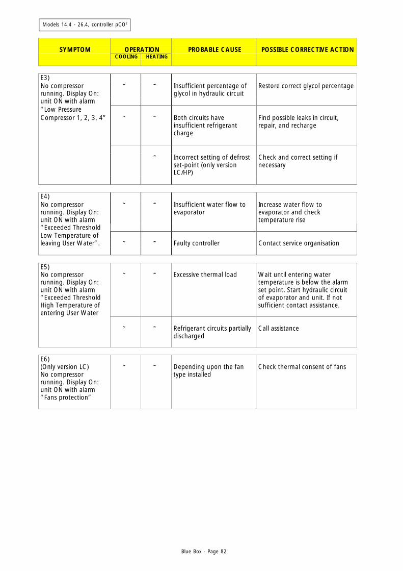
Models 14.4 - 26.4, controller pCO2
Blue Box - Page 82
SYMPTOM
OPERATION
PROBABLE CAUSE
POSSIBLE CORRECTIVE ACTION
COOLING
HEATING
E3) No compressor running. Display On:
⊗ ⊗ Insufficient percentage of glycol in hydraulic circuit
Restore correct glycol percentage
unit ON with alarm “Low Pressure Compressor 1, 2, 3, 4” ⊗ ⊗ Both circuits have
insufficient refrigerant charge
Find possible leaks in circuit, repair, and recharge
⊗ Incorrect setting of defrost
set-point (only version LC/HP)
Check and correct setting if necessary
E4) No compressor running. Display On: unit ON with alarm
⊗ ⊗ Insufficient water flow to evaporator
Increase water flow to evaporator and check temperature rise
“Exceeded Threshold Low Temperature of leaving User Water”. ⊗ ⊗ Faulty controller Contact service organisation E5) No compressor running. Display On: unit ON with alarm “Exceeded Threshold High Temperature of
⊗ ⊗ Excessive thermal load Wait until entering water temperature is below the alarm set point. Start hydraulic circuit of evaporator and unit. If not sufficient contact assistance.
entering User Water ⊗ ⊗ Refrigerant circuits partially
discharged Call assistance
E6) (Only version LC) No compressor running. Display On: unit ON with alarm “Fans protection”
⊗ ⊗ Depending upon the fan type installed
Check thermal consent of fans
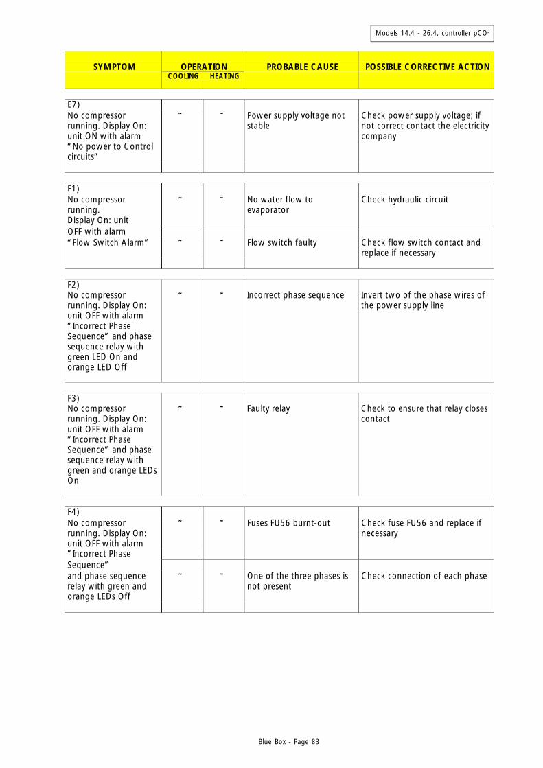
Models 14.4 - 26.4, controller pCO2
Blue Box - Page 83
SYMPTOM
OPERATION
PROBABLE CAUSE
POSSIBLE CORRECTIVE ACTION
COOLING
HEATING
E7) No compressor running. Display On: unit ON with alarm “No power to Control circuits”
⊗ ⊗ Power supply voltage not stable
Check power supply voltage; if not correct contact the electricity company
F1) No compressor running.
⊗ ⊗ No water flow to evaporator
Check hydraulic circuit
Display On: unit OFF with alarm “Flow Switch Alarm” ⊗ ⊗ Flow switch faulty Check flow switch contact and
replace if necessary F2) No compressor running. Display On: unit OFF with alarm ”Incorrect Phase Sequence” and phase sequence relay with green LED On and orange LED Off
⊗ ⊗ Incorrect phase sequence Invert two of the phase wires of the power supply line
F3) No compressor running. Display On: unit OFF with alarm ”Incorrect Phase Sequence” and phase sequence relay with green and orange LEDs On
⊗ ⊗ Faulty relay Check to ensure that relay closes contact
F4) No compressor running. Display On: unit OFF with alarm
⊗ ⊗ Fuses FU56 burnt-out Check fuse FU56 and replace if necessary
”Incorrect Phase Sequence” and phase sequence relay with green and orange LEDs Off
⊗ ⊗ One of the three phases is not present
Check connection of each phase

Models 14.4 - 26.4, controller pCO2
Blue Box - Page 84
SYMPTOM
OPERATION
PROBABLE CAUSE
POSSIBLE CORRECTIVE ACTION
COOLING
HEATING
G) No compressor running. Display On:
⊗ ⊗ No consent from digital input to compressors
Check consent to compressors and close relative contacts
unit ON without alarm ⊗ ⊗ Unit at temperature Normal operation ⊗ ⊗ Compressor fuses burnt-
out Check continuity of fuses; if burnt-out call service
⊗ ⊗ Controller faulty Call service H1) Only 1 compressor running. Display On
⊗ ⊗ Excess refrigerant charge Check refrigerant charge and call service organisation
with alarm “High Pressure Compressor 1 and 2 or 3 and 4”
⊗ ⊗ Problems at the condenser hydraulic circuit
Check flow and temperature of condenser entering water
⊗ ⊗ High pressure switch
incorrectly calibrated or faulty
Check pressure switch setting
⊗ ⊗ Pressostatic valve
incorrectly set Check setting of pressostatic valve and call assistance
H2) Only 1 compressor running. Display On with alarm
⊗ ⊗ Insufficient refrigerant charge due to a leak in the circuit
Call service
“Low Pressure Compressor 1 and 2 or 3 and 4” ⊗ ⊗ Thermostatic valve faulty Call service ⊗ ⊗ Solenoid valve of liquid
refrigerant line faulty (if present)
Call service
⊗ ⊗ Dehydrating filter clogged Call service
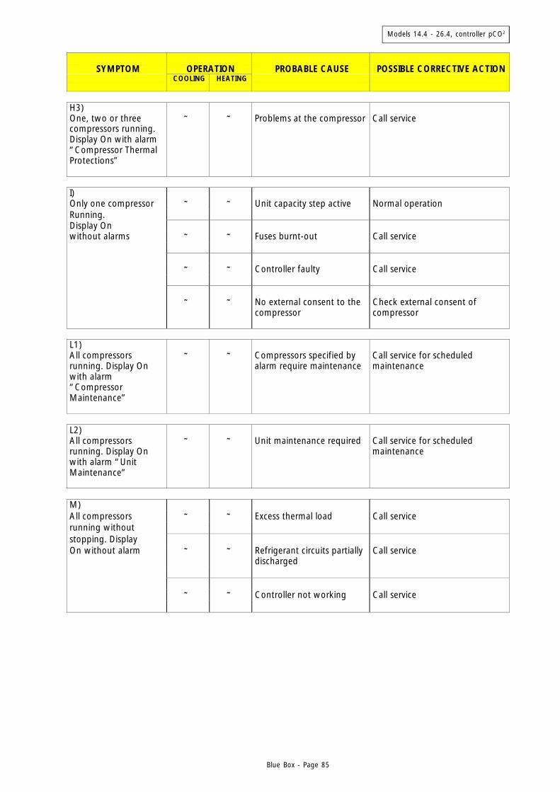
Models 14.4 - 26.4, controller pCO2
Blue Box - Page 85
SYMPTOM
OPERATION
PROBABLE CAUSE
POSSIBLE CORRECTIVE ACTION
COOLING
HEATING
H3) One, two or three compressors running. Display On with alarm “Compressor Thermal Protections”
⊗ ⊗ Problems at the compressor Call service
I) Only one compressor ⊗ ⊗ Unit capacity step active Normal operation Running. Display On without alarms ⊗ ⊗ Fuses burnt-out Call service ⊗ ⊗ Controller faulty Call service ⊗ ⊗ No external consent to the
compressor Check external consent of compressor
L1) All compressors running. Display On with alarm “Compressor Maintenance”
⊗ ⊗ Compressors specified by alarm require maintenance
Call service for scheduled maintenance
L2) All compressors running. Display On with alarm “Unit Maintenance”
⊗ ⊗ Unit maintenance required Call service for scheduled maintenance
M) All compressors ⊗ ⊗ Excess thermal load Call service running without stopping. Display On without alarm ⊗ ⊗ Refrigerant circuits partially
discharged Call service
⊗ ⊗ Controller not working Call service
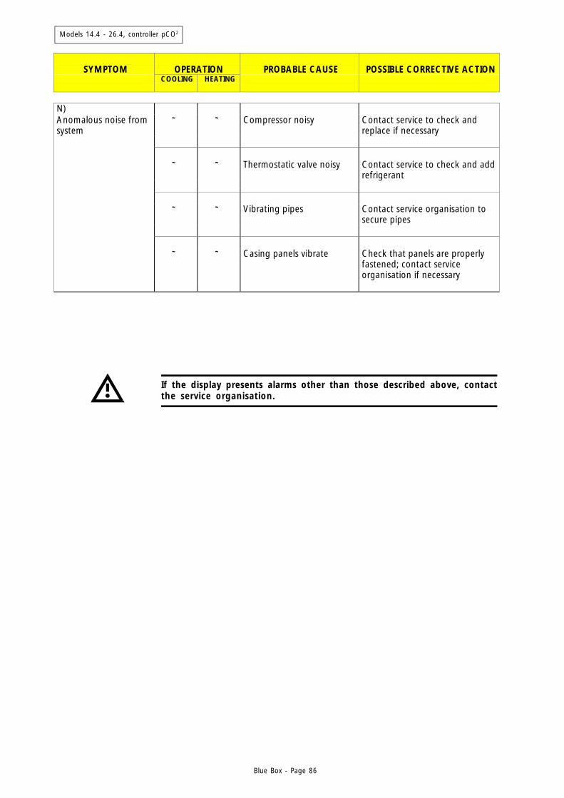
Models 14.4 - 26.4, controller pCO2
Blue Box - Page 86
If the display presents alarms other than those described above, contactthe service organisation.
SYMPTOM
OPERATION
PROBABLE CAUSE
POSSIBLE CORRECTIVE ACTION
COOLING
HEATING
N) Anomalous noise from system
⊗ ⊗ Compressor noisy Contact service to check and replace if necessary
⊗ ⊗ Thermostatic valve noisy Contact service to check and add
refrigerant ⊗ ⊗ Vibrating pipes Contact service organisation to
secure pipes ⊗ ⊗ Casing panels vibrate Check that panels are properly
fastened; contact service organisation if necessary
Blue Box - 87
10 CHECKS DURING OPERATION
- With the unit at steady conditions check that the entering and leaving condenser water temperatures are insidethe operating limits given in the technical specifications.
10.1 Checking the refrigerant charge
- After a few hours of unit operation check that the sight glass moisture indicator has a green coloured core. if thecore is yellow, moisture is present in the circuit. In such a situation the circuit must be dehydrated by a qualifiedtechnician.
- Check the sight glass for air bubbles. A constant passage of bubbles through the sight glass could indicate thatthe refrigerant must be replenished. Occasional bubbles are considered normal.
- A few minutes after the start of the compressors, check that the condensing temperature, equivalent to thepressure read on the pressure gauge, is approximately 8 °C higher than condenser inlet water temperature.Also check that the evaporating temperature, equivalent to the pressure read on the pressure gauge, is 5 °Clower than the evaporator outlet temperature.
- Check that the refrigerant superheating is between 5 and 7 °C; to do this:
1) measure the temperature using a contact thermometer placed on the compressor suction pipeline;2) read the temperature, equivalent to the pressure read on the pressure gauge connected to the compressor
suction side (saturation temperature corresponding to suction pressure); for units charged with R407Crefrigerant, refer to the D.P. (Dew Point) pressure gauge scale.
The difference between the temperatures measured in this manner is equivalent to the superheating value.
- Check that refrigerant subcooling is between 5 and 7 °C; to do this:
1) measure the temperature using a contact thermometer placed on the compressor discharge pipeline;2) read the temperature, equivalent to the pressure read on the pressure gauge connected to the liquid
connection at the condenser outlet (saturation temperature corresponding to condenser delivery pressure);for units charged with R407C refrigerant, refer to the B.P. (Bubble Point) pressure gauge scale.
The difference between the temperature values measured in this manner is equivalent to the subcoolingvalue.

Blue Box - 88
TABLE 6 - CALIBRATION OF SAFETY DEVICES
CAPACITY STEPS
CONTROL ELEMENT SET POINT DIFFERENTIAL SET POINT DIFFERENTIALService calibration (summer) °C 10 2 9 3Service calibration (winter) °C 42 2 43 3
2 4
NOTE:(*) Chiller / Version HP/LC(**) Only version HP/LC with remote condensers/evaporators supplied by Blue Box
ACTIVATION DIFFERENTIAL RESETSET POINT
No-frost setting °C 3 6 manualMaximum pressure switch setting bar 27 7 manualMinimum pressure switch setting bar 2.5 / 0.7 (*) 1 manual (from controller)Evaporator heater setting °C 3 6 automaticDefrost start setting bar 2 -- automaticDefrost end setting bar 18 -- automaticDefrost end thermostat setting °C 5 -- automaticDefrost pressure switch setting bar 16 2 automatic
CONTROL ELEMENT
11. CALIBRATION OF CONTROL EQUIPMENT
11.1 INTRODUCTION
All the control equipment is factory calibrated before the machine is shipped. Control equipment and safetydevices should nonetheless be checked after a reasonable period of operation. Calibration values are given inTables 5 and 6.
All service operations on the control equipment must be carried out byQUALIFIED PERSONNEL ONLY; incorrect calibration values can causeserious damage to the unit and personal injury.
TABLE 5 - CALIBRATION OF CONTROL EQUIPMENT

Blue Box - 89
12. MAINTENANCE AND PERIODIC CHECKS
12. 1 WARNINGS
Al l operat ions descr ibed in this chapter MUST BE PERFORMEDEXCLUSIVELY BY QUALIFIED PERSONNEL.
Make sure that the unit has been disconnected from the power supplybefore carrying out any work or accessing internal parts.
The compressor head and discharge pipeline can reach high temperatures.Always exert caution when working in the vicinity of the compressor.
12.2 INTRODUCTION
Carry out the following periodic checks to ensure the unit is operating correctly:
CHECK PERIOD Check that safety and control devices work correctly as previously described monthly Check all the terminals on electric board and compressor are well locked. Periodic cleaning of the sliding terminals of the contactors should be done: if any damage is found, replace the contactors
monthly
Check the sight glass to verify the refrigerant charge. monthly Check there is no oil leakage from compressor monthly Check there is no water leakage in the hydraulic system monthly If the unit is to be stopped for a long period the hydraulic circuit, including all pipes and heat exchangers, should be drained. This is compulsory if the ambient temperature is expected to fall below the freezing point of the liquid employed.
seasonal operation
Check process water levels monthly Check that the flow switch is operating correctly. monthly Check that the crankcase heater operating correctly and the power supply. monthly Clean metallic filters on water piping monthly Check the colour of the sight glass core (green = no moisture, yellow = moisture present): if it has a yellow colour, change the refrigerant filter
every 4 months
Check that the noise level has not increased. every 4 months

Blue Box - 90
12.3 REPAIRING THE REFRIGERANT CIRCUIT
If repairs have been made to the refrigerant circuit, perform the following steps:
- leak test;- vacuum and dehydration of refrigerant circuit;- refrigerant charge.
If the circuit is to be emptied, use the appropriate equipment to collectthe refrigerant.
12.3.1 Leak test
Charge the refrigerant circuit to a pressure of 15 bar with dry nitrogen gas by means of a cylinder fitted with apressure reducer. Check the circuit for leaks with a leak detector. The formation of bubbles or foam indicates thepresence of leaks.If leaks are found during the test, empty the refrigerant circuit and then repair the point of leakage by weldingwith appropriate alloys.
Do not use oxygen instead of nitrogen: explosion hazard.
12.3.2 High vacuum and dehydration of the refrigerant circuit
To generate a high vacuum in the refrigerant circuit use a high vacuum pump able to reach 0.1 mbar of absolutepressure with a flow rate of 10 m3/h. With this type of pump, a single vacuum cycle is normally sufficient to reachan absolute pressure of 0.1 mbar.If this type of pump is not available, or in the event that the circuit has been left open for a long period of time,you are strongly advised to use the triple evacuation method. This procedure is also prescribed in the event ofmoisture in the refrigerant circuit.
Connect the vacuum pump to the charge connector.Proceed as follows:
- Evacuate the circuit to a pressure of at least 35 mbar absolute. Charge the circuit with nitrogen to a relativepressure of approx. 1 bar.
- Repeat the operation described above.
- Repeat the operation described above for the third time in order to reach the highest degree of vacuum possible.
This procedure should guarantee the elimination of up to 99% of contaminants.
Blue Box - 91
12.3.3 Refrigerant charge
- Connect the refrigerant gas cylinder to the male 1/4 SAE charge connector on the liquid line and allow a smallamount of gas to escape in order to purge the connection hose of air.
- The circuit must be charged exclusively with liquid; therefore, if the cylinder is not equipped with a dip pipe itmust be turned upside-down.
Units operating with R407C must be charged exclusively with liquidrefrigerant by way of the charge connection on the liquid line.
12.4 ENVIRONMENTAL CONSIDERATIONS
Laws governing the use of substances detrimental to the ozone layer prohibit the dispersal of refrigerant gases inthe environment, obliging users to recover refrigerants at the end of their useful life and consign them to thedealer or to specific collection centres.Refrigerants R22 and R407C are mentioned among substances subject to special monitoring regimes establishedby law, and as such they are subject to the prescriptions indicated above.
Use special care during maintenance work in order to limit the risk ofrefrigerant leakage as far as possible.
Blue Box - 92
13. DECOMMISSIONING THE UNIT
When the unit has reached the end of its useful life and must therefore be removed and replaced, adhere to thefollowing rules:
- the refrigerant must be recovered by a qualified technician and sent to an authorised collection centre;- also the compressor lubrication oil must be recovered and sent to a collection centre;- the structure and components, if unusable, must be stripped down and separated according to the material
type; this is particularly important for copper and aluminium, which are fairly abundant on the machine.
This procedure is designed to assist the work of collection, disposal, and recovery specialists and to reduce theassociated environmental impact.
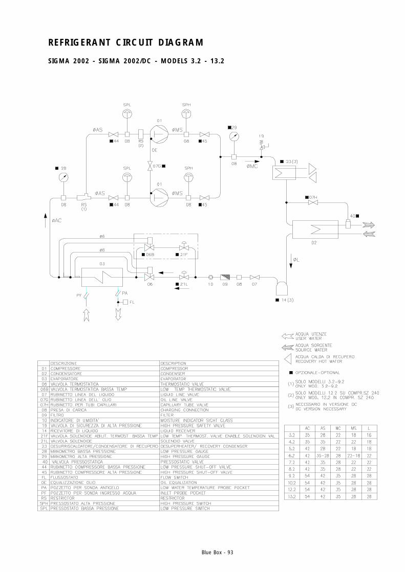
Blue Box - 93
REFRIGERANT CIRCUIT DIAGRAM
SIGMA 2002 - SIGMA 2002/DC - MODELS 3.2 - 13.2
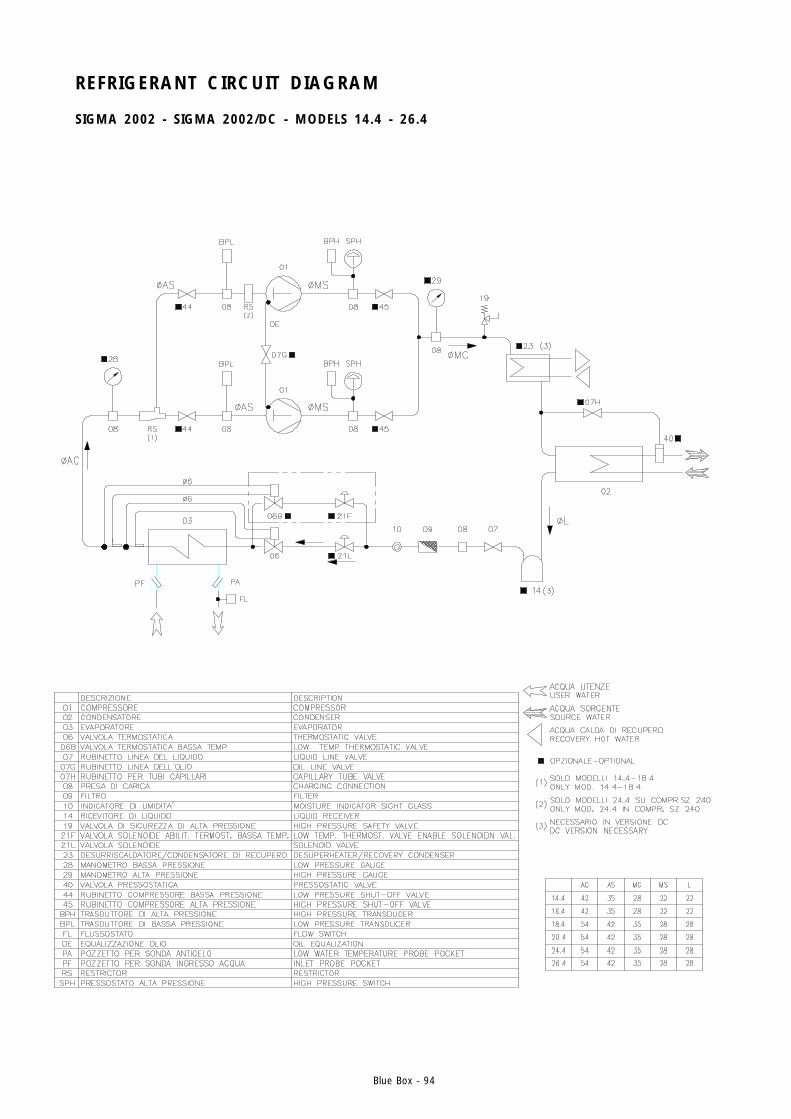
Blue Box - 94
REFRIGERANT CIRCUIT DIAGRAM
SIGMA 2002 - SIGMA 2002/DC - MODELS 14.4 - 26.4
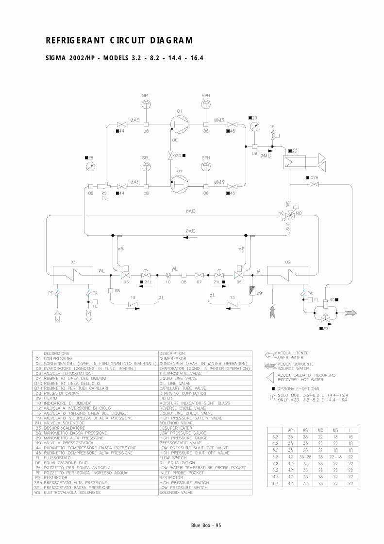
Blue Box - 95
REFRIGERANT CIRCUIT DIAGRAM
SIGMA 2002/HP - MODELS 3.2 - 8.2 - 14.4 - 16.4
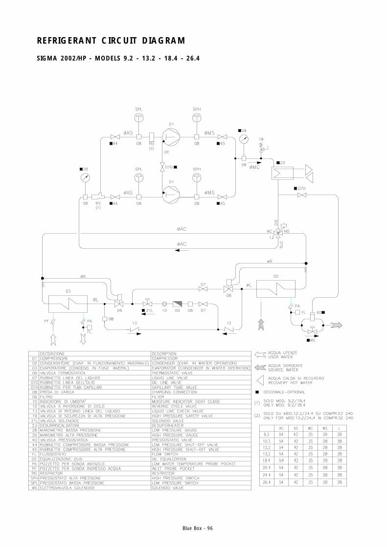
Blue Box - 96
REFRIGERANT CIRCUIT DIAGRAM
SIGMA 2002/HP - MODELS 9.2 - 13.2 - 18.4 - 26.4
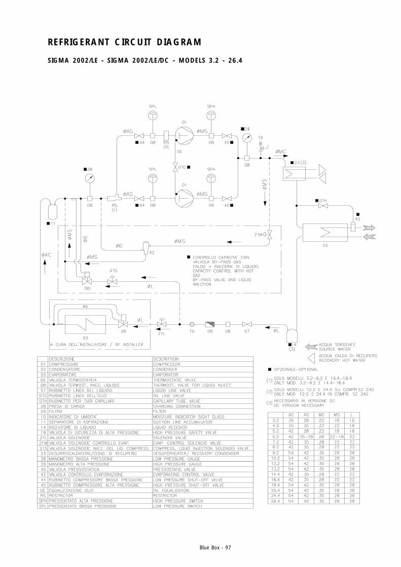
Blue Box - 97
REFRIGERANT CIRCUIT DIAGRAM
SIGMA 2002/LE - SIGMA 2002/LE/DC - MODELS 3.2 - 26.4
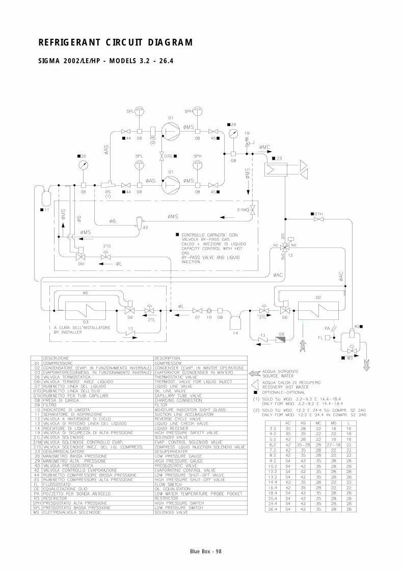
Blue Box - 98
REFRIGERANT CIRCUIT DIAGRAM
SIGMA 2002/LE/HP - MODELS 3.2 - 26.4
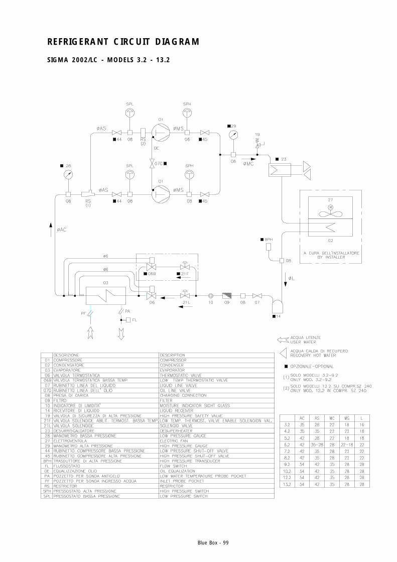
Blue Box - 99
REFRIGERANT CIRCUIT DIAGRAM
SIGMA 2002/LC - MODELS 3.2 - 13.2
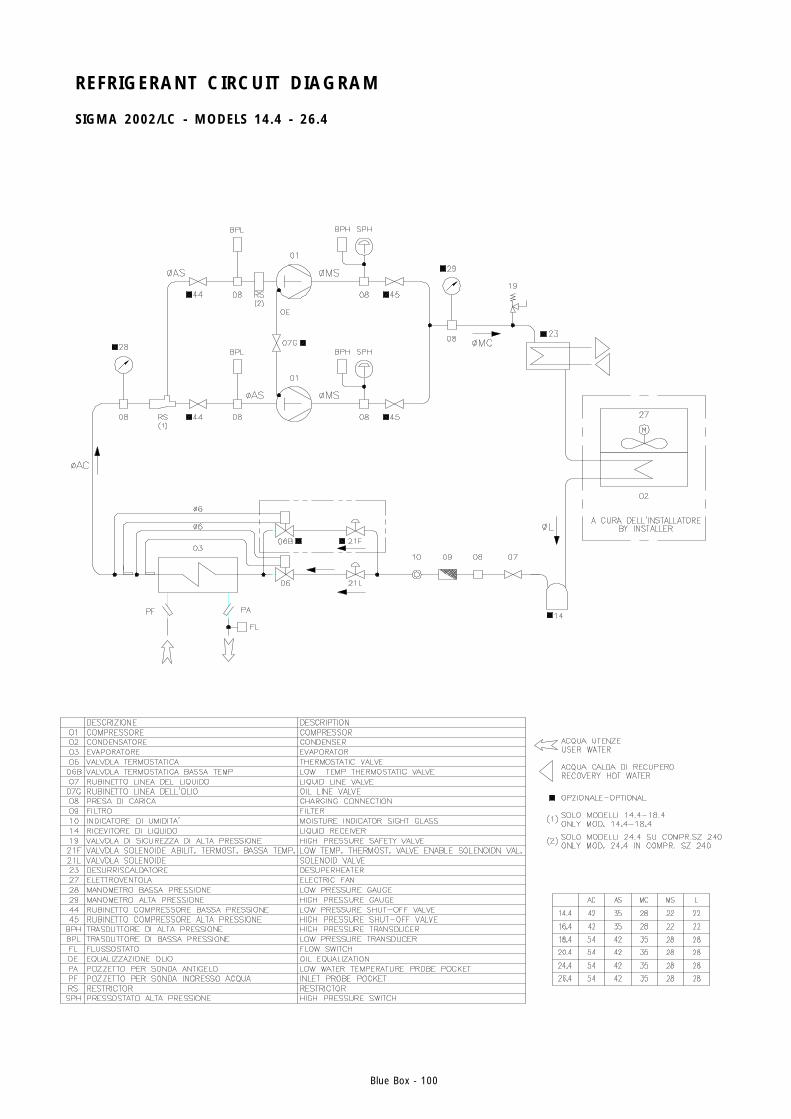
Blue Box - 100
REFRIGERANT CIRCUIT DIAGRAM
SIGMA 2002/LC - MODELS 14.4 - 26.4
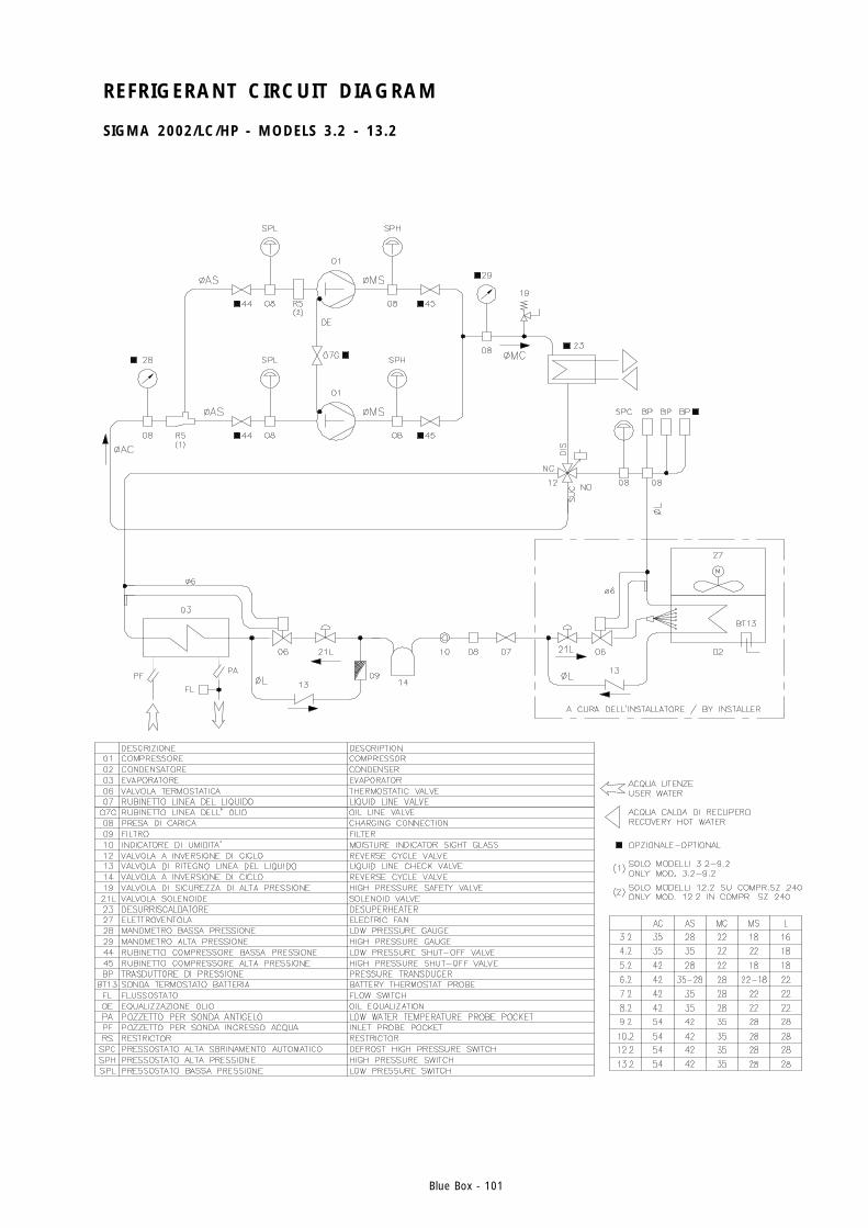
Blue Box - 101
REFRIGERANT CIRCUIT DIAGRAM
SIGMA 2002/LC/HP - MODELS 3.2 - 13.2
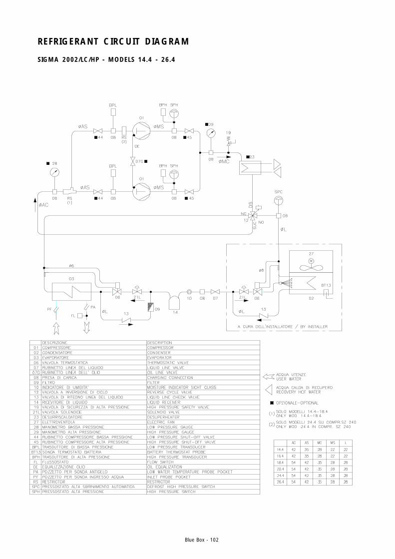
Blue Box - 102
REFRIGERANT CIRCUIT DIAGRAM
SIGMA 2002/LC/HP - MODELS 14.4 - 26.4
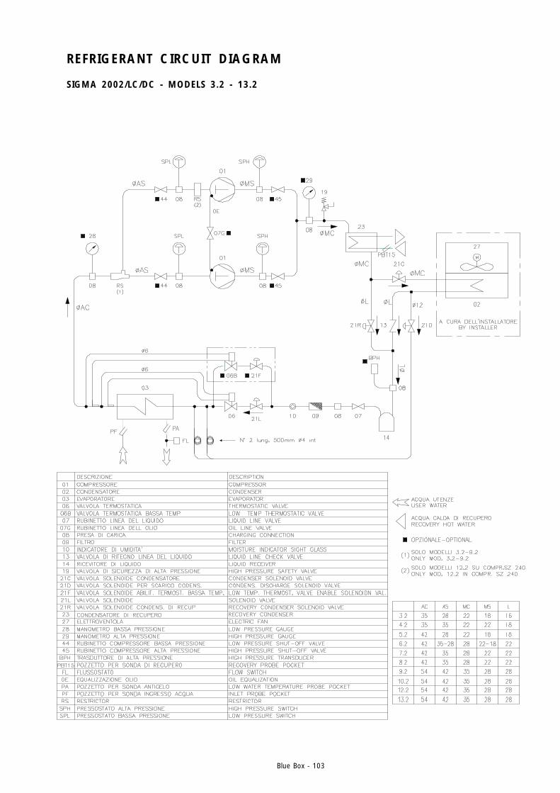
Blue Box - 103
REFRIGERANT CIRCUIT DIAGRAM
SIGMA 2002/LC/DC - MODELS 3.2 - 13.2
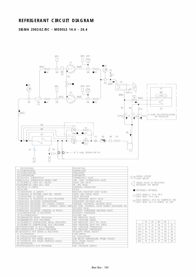
Blue Box - 104
REFRIGERANT CIRCUIT DIAGRAM
SIGMA 2002/LC/DC - MODELS 14.4 - 26.4

Blue Box - 105
DIMENSIONS, WEIGHTS AND HYDRAULIC CONNECTIONS
SIGMA 2002 - MODELS 3.2 - 7.2
TAGLIA A B + C D E F + G H3.2 - 5.2 216,5 466 279,5 214 670 1726.2 - 7.2 242 519 201 310,5 527 218,5
TAGLIA Uin Uout Cin Cout3.2 - 5.2 G 1" 1/4 M G 1" 1/4 M G 1" 1/4 M G 1" 1/4 M6.2 - 7.2 G 2" M G 2" M G 2" M G 2" M
V ERS. TAGLIA A B C + D E + F G + H Rin Rout3.2 - 5.2 216,5 250 495,5 549 507 G 1" F G 1" F6.2 - 7.2 242 250 470 574 482 G 1" F G 1" F3.2 - 5.2 216,5 466 279,5 549 507 G 1" 1/4 M G 1" 1/4 M6.2 - 7.2 242 519 201 574 482 G 2" M G 2" M
DS
DC
Uin
Cout
Rout *
Cin
Rin
Uout
Ep
*
Epf *
Epf *
Fsc *
Fsc *
Fsc*
Es
Epf*
105623048
BA
962
41756
797162
959
EpfQUADRO ELETTRICO RIFASAMENTO UNITA'
POWER FACTOR CORRECTION ELECTRICAL PANEL
EsINGRESSO ALIMENTAZIONE ELETTRICA
ELECTRICAL SUPPLY INLET
SPAZI DI INSTALLAZIONECLEARANCES
Uout
CHILLER, HP, LC, HP/LC
LE, HP/LE
H WATER OUTLET EVAPORATING
REFRIGERANT CONNECTION LIQUID
USER WATER OUTLET
USCITA ACQUA EVAPORATORE
CONNESSIONI REFRIG. LIQUIDO
USCITA ACQUA UTILIZZO
Cin
CHILLER, H, HP, LE, HP/LE
LC, HP/LC REFRIGERANT CONNECTION LIQUID
CONDENSING WATER INLET
CONNESSIONI REFRIG. LIQUIDO
INGRESSO ACQUA CONDENSAZIONE
Cout
CHILLER, H, HP, LE, HP/LE
LC, HP/LC REFRIGERANT CONNECTION DISCARGE
CONDENSING WATER OUTLET
CONNESSIONI REFRIG. MANDATA
USCITA ACQUA CONDENSAZIONE
Rin CHILLER, HP, LC, LE RECOVERY WATER INLET
INGRESSO ACQUA RECUPERO
Rout CHILLER, HP, LC, LE RECOVERY WATER OUTLET
USCITA ACQUA RECUPERO
FscREGOLATORE DI GIRI VERSIONE LCFAN SPEED CONTROL LC VERSION
EpQUADRO ELETTRICOELECTRICAL PANEL
* OPTIONAL
800
800
800 800
1334
Uin
CHILLER, HP, LC, HP/LC
LE, HP/LE
H WATER INLET EVAPORATING
REFRIGERANT CONNECTION SUCTION
USER WATER INLET
INGRESSO ACQUA EVAPORATORE
CONNESSIONI REFRIG. ASPIRAZIONE
INGRESSO ACQUA UTILIZZO
CD
H G F E
1534
200
TAGLIA A B + C D E F + G H3.2 - 5.2 216,5 466 279,5 214 670 1726.2 - 7.2 242 519 201 310,5 527 218,5
TAGLIA Uin Uout Cin Cout3.2 - 5.2 G 1" 1/4 M G 1" 1/4 M G 1" 1/4 M G 1" 1/4 M6.2 - 7.2 G 2" M G 2" M G 2" M G 2" M
VERS. TAGLIA A B C + D E + F G + H Rin Rout3.2 - 5.2 216,5 250 495,5 549 507 G 1" F G 1" F6.2 - 7.2 242 250 470 574 482 G 1" F G 1" F3.2 - 5.2 216,5 466 279,5 549 507 G 1" 1/4 M G 1" 1/4 M6.2 - 7.2 242 519 201 574 482 G 2" M G 2" M
DS
DC
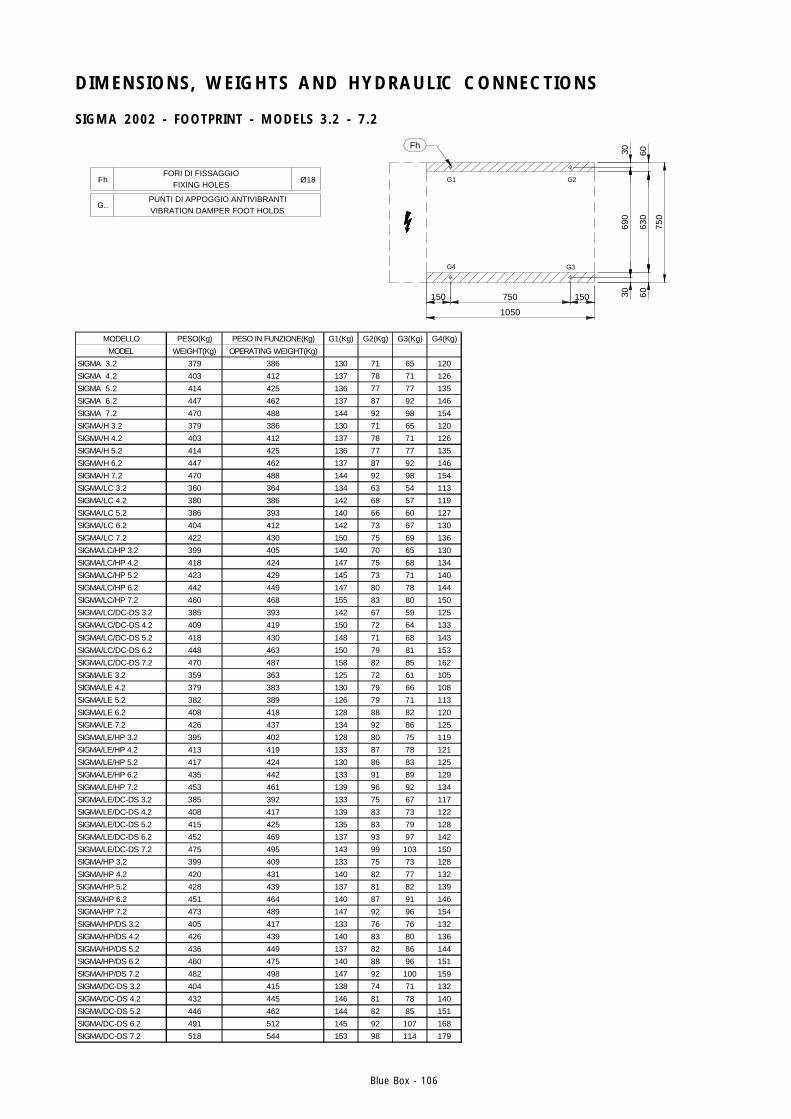
Blue Box - 106
DIMENSIONS, WEIGHTS AND HYDRAULIC CONNECTIONS
SIGMA 2002 - FOOTPRINT - MODELS 3.2 - 7.2
Fh
Ø18 G2G1
G3G4
150750150 30 6063
060
1050
750
690
30
FhFORI DI FISSAGGIO
FIXING HOLES
G..PUNTI DI APPOGGIO ANTIVIBRANTIVIBRATION DAMPER FOOT HOLDS
MODELLO PESO(Kg) PESO IN FUNZIONE(Kg) G1(Kg) G2(Kg) G3(Kg) G4(Kg)
MODEL WEIGHT(Kg) OPERATING WEIGHT(Kg)
SIGMA 3.2 379 386 130 71 65 120
SIGMA 4.2 403 412 137 78 71 126
SIGMA 5.2 414 425 136 77 77 135
SIGMA 6.2 447 462 137 87 92 146
SIGMA 7.2 470 488 144 92 98 154
SIGMA/H 3.2 379 386 130 71 65 120
SIGMA/H 4.2 403 412 137 78 71 126
SIGMA/H 5.2 414 425 136 77 77 135
SIGMA/H 6.2 447 462 137 87 92 146
SIGMA/H 7.2 470 488 144 92 98 154
SIGMA/LC 3.2 360 364 134 63 54 113
SIGMA/LC 4.2 380 386 142 68 57 119
SIGMA/LC 5.2 386 393 140 66 60 127
SIGMA/LC 6.2 404 412 142 73 67 130
SIGMA/LC 7.2 422 430 150 75 69 136
SIGMA/LC/HP 3.2 399 405 140 70 65 130
SIGMA/LC/HP 4.2 418 424 147 75 68 134
SIGMA/LC/HP 5.2 423 429 145 73 71 140
SIGMA/LC/HP 6.2 442 449 147 80 78 144
SIGMA/LC/HP 7.2 460 468 155 83 80 150
SIGMA/LC/DC-DS 3.2 385 393 142 67 59 125
SIGMA/LC/DC-DS 4.2 409 419 150 72 64 133
SIGMA/LC/DC-DS 5.2 418 430 148 71 68 143
SIGMA/LC/DC-DS 6.2 448 463 150 79 81 153
SIGMA/LC/DC-DS 7.2 470 487 158 82 85 162
SIGMA/LE 3.2 359 363 125 72 61 105
SIGMA/LE 4.2 379 383 130 79 66 108
SIGMA/LE 5.2 382 389 126 79 71 113
SIGMA/LE 6.2 408 418 128 88 82 120
SIGMA/LE 7.2 426 437 134 92 86 125
SIGMA/LE/HP 3.2 395 402 128 80 75 119
SIGMA/LE/HP 4.2 413 419 133 87 78 121
SIGMA/LE/HP 5.2 417 424 130 86 83 125
SIGMA/LE/HP 6.2 435 442 133 91 89 129
SIGMA/LE/HP 7.2 453 461 139 96 92 134
SIGMA/LE/DC-DS 3.2 385 392 133 75 67 117
SIGMA/LE/DC-DS 4.2 408 417 139 83 73 122
SIGMA/LE/DC-DS 5.2 415 425 135 83 79 128
SIGMA/LE/DC-DS 6.2 452 469 137 93 97 142
SIGMA/LE/DC-DS 7.2 475 495 143 99 103 150
SIGMA/HP 3.2 399 409 133 75 73 128
SIGMA/HP 4.2 420 431 140 82 77 132
SIGMA/HP 5.2 428 439 137 81 82 139
SIGMA/HP 6.2 451 464 140 87 91 146
SIGMA/HP 7.2 473 489 147 92 96 154
SIGMA/HP/DS 3.2 405 417 133 76 76 132
SIGMA/HP/DS 4.2 426 439 140 83 80 136
SIGMA/HP/DS 5.2 436 449 137 82 86 144
SIGMA/HP/DS 6.2 460 475 140 88 96 151
SIGMA/HP/DS 7.2 482 498 147 92 100 159
SIGMA/DC-DS 3.2 404 415 138 74 71 132
SIGMA/DC-DS 4.2 432 445 146 81 78 140
SIGMA/DC-DS 5.2 446 462 144 82 85 151
SIGMA/DC-DS 6.2 491 512 145 92 107 168
SIGMA/DC-DS 7.2 518 544 153 98 114 179
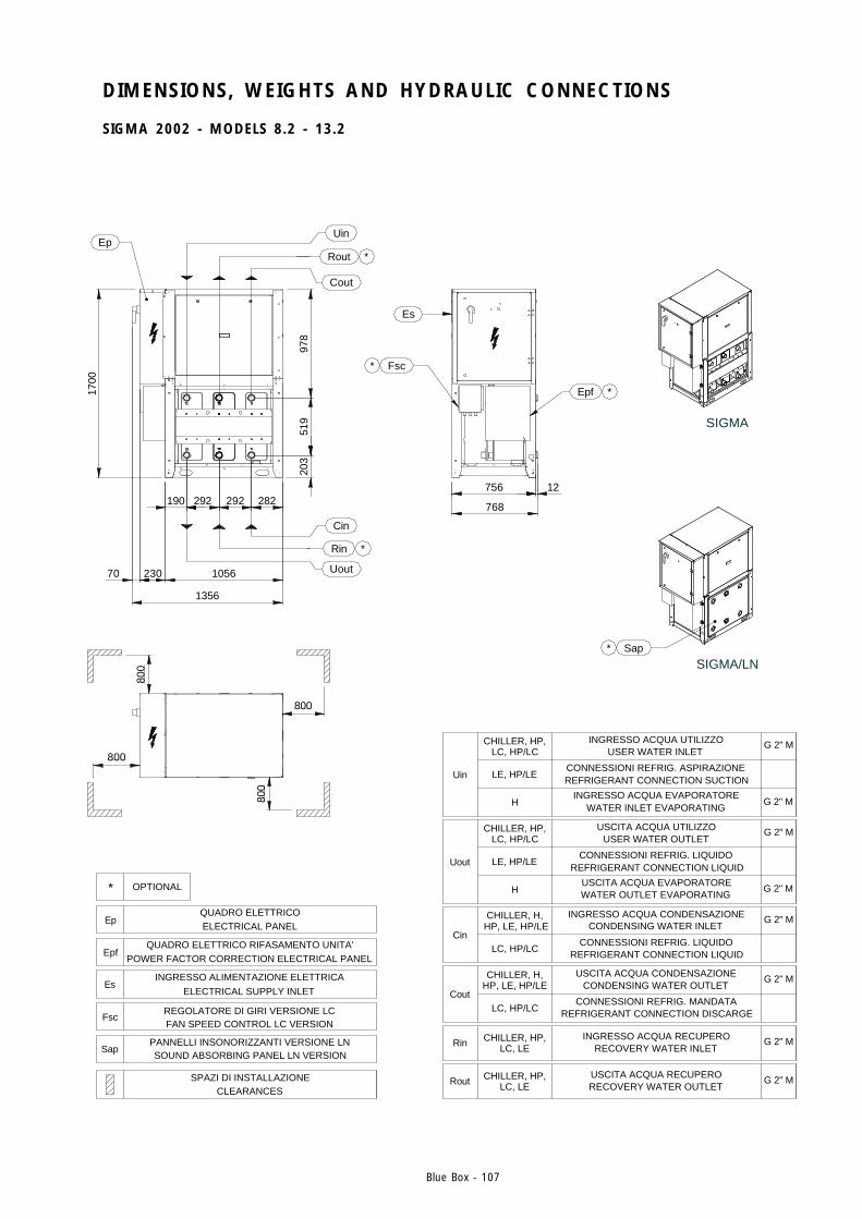
Blue Box - 107
DIMENSIONS, WEIGHTS AND HYDRAULIC CONNECTIONS
SIGMA 2002 - MODELS 8.2 - 13.2
Es
Fsc
800
* OPTIONAL
SapPANNELLI INSONORIZZANTI VERSIONE LNSOUND ABSORBING PANEL LN VERSION
EpQUADRO ELETTRICOELECTRICAL PANEL
FscREGOLATORE DI GIRI VERSIONE LCFAN SPEED CONTROL LC VERSION
SPAZI DI INSTALLAZIONECLEARANCES
EsINGRESSO ALIMENTAZIONE ELETTRICA
ELECTRICAL SUPPLY INLET
EpfQUADRO ELETTRICO RIFASAMENTO UNITA'
POWER FACTOR CORRECTION ELECTRICAL PANEL
800
1356
1056
190
1700
70 230
800
Ep
519
800
203
292292 282
*
Cin
Rin
Uout
978
Rout
Uin
*
Cout
*
Uin
G 2" MCHILLER, HP, LC, HP/LC
LE, HP/LE
H G 2" MWATER INLET EVAPORATING
REFRIGERANT CONNECTION SUCTION
USER WATER INLET
INGRESSO ACQUA EVAPORATORE
CONNESSIONI REFRIG. ASPIRAZIONE
INGRESSO ACQUA UTILIZZO
Rout G 2" MCHILLER, HP, LC, LE RECOVERY WATER OUTLET
USCITA ACQUA RECUPERO
Rin G 2" MCHILLER, HP, LC, LE RECOVERY WATER INLET
INGRESSO ACQUA RECUPERO
Cout
G 2" MCHILLER, H,HP, LE, HP/LE
LC, HP/LC REFRIGERANT CONNECTION DISCARGE
CONDENSING WATER OUTLET
CONNESSIONI REFRIG. MANDATA
USCITA ACQUA CONDENSAZIONE
Cin
G 2" MCHILLER, H, HP, LE, HP/LE
LC, HP/LCREFRIGERANT CONNECTION LIQUID
CONDENSING WATER INLET
CONNESSIONI REFRIG. LIQUIDO
INGRESSO ACQUA CONDENSAZIONE
Uout
G 2" MCHILLER, HP, LC, HP/LC
LE, HP/LE
H G 2" MWATER OUTLET EVAPORATING
REFRIGERANT CONNECTION LIQUID
USER WATER OUTLET
USCITA ACQUA EVAPORATORE
CONNESSIONI REFRIG. LIQUIDO
USCITA ACQUA UTILIZZO
Sap
Epf
12
768
756
*
*
SIGMA/LN
SIGMA
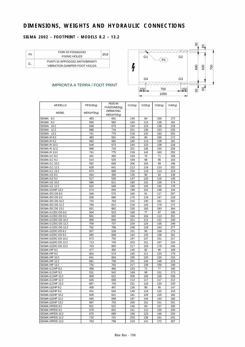
Blue Box - 108
DIMENSIONS, WEIGHTS AND HYDRAULIC CONNECTIONS
SIGMA 2002 - FOOTPRINT - MODELS 8.2 - 13.2
Ø18
1050150
G..PUNTI DI APPOGGIO ANTIVIBRANTIVIBRATION DAMPER FOOT HOLDS
FhFORI DI FISSAGGIO
FIXING HOLES
IMPRONTA A TERRA / FOOT PRINT750
Fh
G4
G1
30 60
3069
0
750
630
60150
G3
G2
MODELLO PESO(Kg)PESO IN
FUNZIONE(Kg)G1(Kg) G2(Kg) G3(Kg) G4(Kg)
MODEL WEIGHT(Kg)OPERATING WEIGHT(Kg)
SIGMA 8.2 483 501 145 84 100 172SIGMA 9.2 560 582 160 113 128 181SIGMA 10.2 648 673 194 123 138 218SIGMA 12.2 688 716 201 136 153 226SIGMA 13.2 741 775 218 142 163 252SIGMA /H 8.2 483 501 145 84 100 172SIGMA /H 9.2 560 582 160 113 128 181SIGMA /H 10.2 648 673 194 123 138 218SIGMA /H 12.2 688 716 201 136 153 226SIGMA /H 13.2 741 775 218 142 163 252SIGMA /LC 8.2 441 450 154 70 71 155SIGMA /LC 9.2 514 525 169 98 95 163SIGMA /LC 10.2 592 605 206 104 99 196SIGMA /LC 12.2 628 641 213 116 110 202SIGMA /LC 13.2 673 689 233 119 114 223SIGMA /LE 8.2 444 456 135 90 92 139SIGMA /LE 9.2 517 530 147 120 118 145SIGMA /LE 10.2 596 611 180 131 126 174SIGMA /LE 12.2 632 648 185 145 140 178SIGMA /LE/HP 13.2 674 693 199 152 148 194SIGMA /DC-DS 8.2 546 575 160 91 117 207SIGMA /DC-DS 9.2 628 660 176 119 147 218SIGMA /DC-DS 10.2 724 763 210 130 161 262SIGMA /DC-DS 12.2 769 812 218 143 179 272SIGMA /DC-DS 13.2 831 882 235 150 193 304SIGMA /LC/DC-DS 8.2 504 523 169 77 87 190SIGMA /LC/DC-DS 9.2 581 602 184 104 113 201SIGMA /LC/DC-DS 10.2 669 694 221 112 121 240SIGMA /LC/DC-DS 12.2 709 737 229 124 135 249SIGMA /LC/DC-DS 13.2 762 796 248 128 143 277SIGMA /LE/DC-DS 8.2 507 528 151 95 109 173SIGMA /LE/DC-DS 9.2 585 608 164 125 138 181SIGMA /LE/DC-DS 10.2 673 702 197 137 151 217SIGMA /LE/DC-DS 12.2 713 745 203 151 167 224SIGMA /LE/DC-DS 13.2 763 800 217 159 179 245SIGMA /HP 8.2 477 492 145 82 96 169SIGMA /HP 9.2 554 574 160 111 124 179SIGMA /HP 10.2 641 663 195 120 133 215SIGMA /HP 12.2 681 706 201 134 148 223SIGMA /HP 13.2 734 764 217 139 159 249SIGMA /LC/HP 8.2 458 466 153 71 77 165SIGMA /LC/HP 9.2 531 542 169 99 101 173SIGMA /LC/HP 10.2 609 622 206 105 105 206SIGMA /LC/HP 12.2 645 659 213 117 117 212SIGMA /LC/HP 13.2 687 703 231 119 120 233SIGMA /LE/HP 8.2 458 467 136 89 95 147SIGMA /LE/HP 9.2 531 543 149 119 122 153SIGMA /LE/HP 10.2 609 621 181 129 129 182SIGMA /LE/HP 12.2 645 659 187 144 143 185SIGMA /LE/HP 13.2 687 703 200 151 151 201SIGMA /HP/DS 8.2 501 522 146 84 107 185SIGMA /HP/DS 9.2 579 602 161 112 135 194SIGMA /HP/DS 10.2 670 699 196 123 146 234SIGMA /HP/DS 12.2 710 741 203 136 161 241SIGMA /HP/DS 13.2 763 799 219 141 172 267
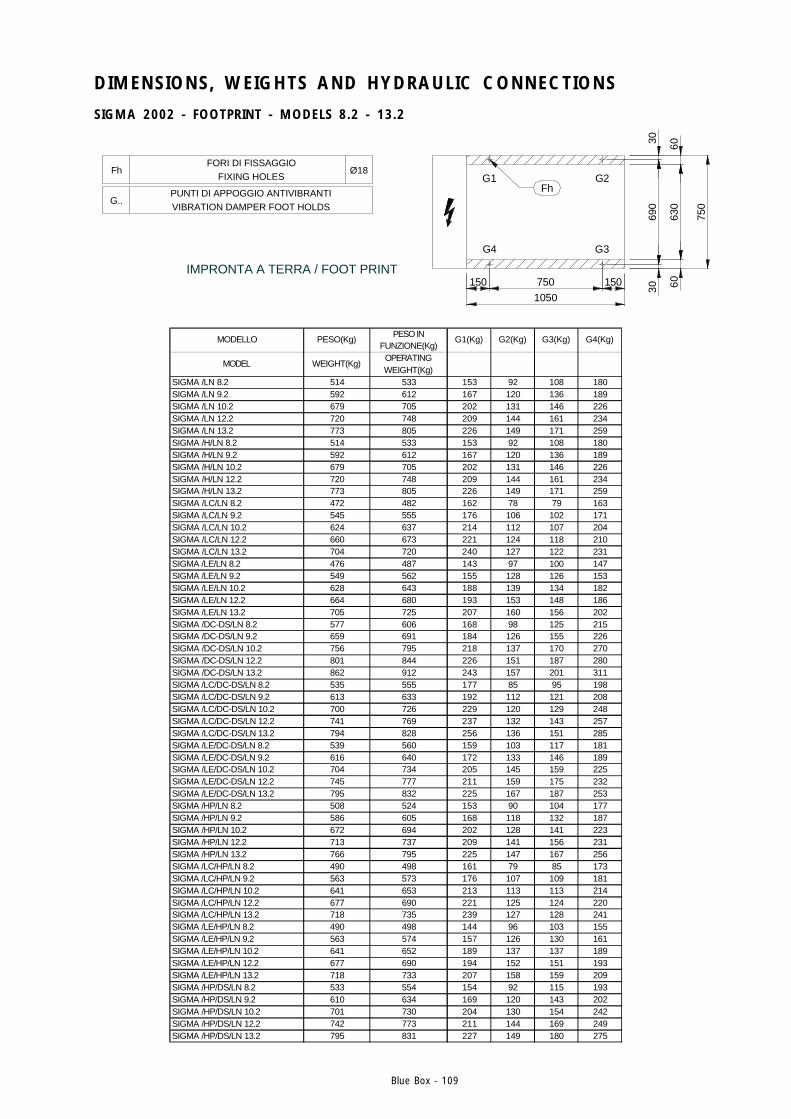
Blue Box - 109
DIMENSIONS, WEIGHTS AND HYDRAULIC CONNECTIONS
SIGMA 2002 - FOOTPRINT - MODELS 8.2 - 13.2
Ø18
1050150
G..PUNTI DI APPOGGIO ANTIVIBRANTIVIBRATION DAMPER FOOT HOLDS
FhFORI DI FISSAGGIO
FIXING HOLES
IMPRONTA A TERRA / FOOT PRINT750
Fh
G4
G1
30 60
3069
0
750
630
60150
G3
G2
MODELLO PESO(Kg)PESO IN
FUNZIONE(Kg)G1(Kg) G2(Kg) G3(Kg) G4(Kg)
MODEL WEIGHT(Kg)OPERATING WEIGHT(Kg)
SIGMA /LN 8.2 514 533 153 92 108 180SIGMA /LN 9.2 592 612 167 120 136 189SIGMA /LN 10.2 679 705 202 131 146 226SIGMA /LN 12.2 720 748 209 144 161 234SIGMA /LN 13.2 773 805 226 149 171 259SIGMA /H/LN 8.2 514 533 153 92 108 180SIGMA /H/LN 9.2 592 612 167 120 136 189SIGMA /H/LN 10.2 679 705 202 131 146 226SIGMA /H/LN 12.2 720 748 209 144 161 234SIGMA /H/LN 13.2 773 805 226 149 171 259SIGMA /LC/LN 8.2 472 482 162 78 79 163SIGMA /LC/LN 9.2 545 555 176 106 102 171SIGMA /LC/LN 10.2 624 637 214 112 107 204SIGMA /LC/LN 12.2 660 673 221 124 118 210SIGMA /LC/LN 13.2 704 720 240 127 122 231SIGMA /LE/LN 8.2 476 487 143 97 100 147SIGMA /LE/LN 9.2 549 562 155 128 126 153SIGMA /LE/LN 10.2 628 643 188 139 134 182SIGMA /LE/LN 12.2 664 680 193 153 148 186SIGMA /LE/LN 13.2 705 725 207 160 156 202SIGMA /DC-DS/LN 8.2 577 606 168 98 125 215SIGMA /DC-DS/LN 9.2 659 691 184 126 155 226SIGMA /DC-DS/LN 10.2 756 795 218 137 170 270SIGMA /DC-DS/LN 12.2 801 844 226 151 187 280SIGMA /DC-DS/LN 13.2 862 912 243 157 201 311SIGMA /LC/DC-DS/LN 8.2 535 555 177 85 95 198SIGMA /LC/DC-DS/LN 9.2 613 633 192 112 121 208SIGMA /LC/DC-DS/LN 10.2 700 726 229 120 129 248SIGMA /LC/DC-DS/LN 12.2 741 769 237 132 143 257SIGMA /LC/DC-DS/LN 13.2 794 828 256 136 151 285SIGMA /LE/DC-DS/LN 8.2 539 560 159 103 117 181SIGMA /LE/DC-DS/LN 9.2 616 640 172 133 146 189SIGMA /LE/DC-DS/LN 10.2 704 734 205 145 159 225SIGMA /LE/DC-DS/LN 12.2 745 777 211 159 175 232SIGMA /LE/DC-DS/LN 13.2 795 832 225 167 187 253SIGMA /HP/LN 8.2 508 524 153 90 104 177SIGMA /HP/LN 9.2 586 605 168 118 132 187SIGMA /HP/LN 10.2 672 694 202 128 141 223SIGMA /HP/LN 12.2 713 737 209 141 156 231SIGMA /HP/LN 13.2 766 795 225 147 167 256SIGMA /LC/HP/LN 8.2 490 498 161 79 85 173SIGMA /LC/HP/LN 9.2 563 573 176 107 109 181SIGMA /LC/HP/LN 10.2 641 653 213 113 113 214SIGMA /LC/HP/LN 12.2 677 690 221 125 124 220SIGMA /LC/HP/LN 13.2 718 735 239 127 128 241SIGMA /LE/HP/LN 8.2 490 498 144 96 103 155SIGMA /LE/HP/LN 9.2 563 574 157 126 130 161SIGMA /LE/HP/LN 10.2 641 652 189 137 137 189SIGMA /LE/HP/LN 12.2 677 690 194 152 151 193SIGMA /LE/HP/LN 13.2 718 733 207 158 159 209SIGMA /HP/DS/LN 8.2 533 554 154 92 115 193SIGMA /HP/DS/LN 9.2 610 634 169 120 143 202SIGMA /HP/DS/LN 10.2 701 730 204 130 154 242SIGMA /HP/DS/LN 12.2 742 773 211 144 169 249SIGMA /HP/DS/LN 13.2 795 831 227 149 180 275

Blue Box - 110
DIMENSIONS, WEIGHTS AND HYDRAULIC CONNECTIONS
SIGMA 2002 - MODEL 14.4
800
* OPTIONAL
SapPANNELLI INSONORIZZANTI VERSIONE LNSOUND ABSORBING PANEL LN VERSION
EpQUADRO ELETTRICOELECTRICAL PANEL
FscREGOLATORE DI GIRI VERSIONE LCFAN SPEED CONTROL LC VERSION
SPAZI DI INSTALLAZIONECLEARANCES
EsINGRESSO ALIMENTAZIONE ELETTRICA
ELECTRICAL SUPPLY INLET
EpfQUADRO ELETTRICO RIFASAMENTO UNITA'
POWER FACTOR CORRECTION ELECTRICAL PANEL
800
263,5 310,5
*Epf
Epf *
Uin
Rout
Cin
Rin
Uout
*
*
Rin
Uout
Cin
Uin
Rout
Cout
*
*
Uin
G 2" MCHILLER, HP, LC, HP/LC
LE, HP/LE
H G 2" MWATER INLET EVAPORATING
REFRIGERANT CONNECTION SUCTION
USER WATER INLET
INGRESSO ACQUA EVAPORATORE
CONNESSIONI REFRIG. ASPIRAZIONE
INGRESSO ACQUA UTILIZZO
Rout CHILLER, HP, LC, LE RECOVERY WATER OUTLET
USCITA ACQUA RECUPERO
Rin CHILLER, HP, LC, LE RECOVERY WATER INLET
INGRESSO ACQUA RECUPERO
Cout
G 2" MCHILLER, H,HP, LE, HP/LE
LC, HP/LC REFRIGERANT CONNECTION DISCARGE
CONDENSING WATER OUTLET
CONNESSIONI REFRIG. MANDATA
USCITA ACQUA CONDENSAZIONE
Cin
G 2" MCHILLER, H,HP, LE, HP/LE
LC, HP/LC REFRIGERANT CONNECTION LIQUID
CONDENSING WATER INLET
CONNESSIONI REFRIG. LIQUIDO
INGRESSO ACQUA CONDENSAZIONE
Uout
G 2" MCHILLER, HP, LC, HP/LC
LE, HP/LE
H G 2" MWATER OUTLET EVAPORATING
REFRIGERANT CONNECTION LIQUID
USER WATER OUTLET
USCITA ACQUA EVAPORATORE
CONNESSIONI REFRIG. LIQUIDO
USCITA ACQUA UTILIZZO
1787
978
177 801
756Fsc* 45
*Fsc
Ep
Fsc*
70 300
Es
Cout
250
Epf *
263,5
800
1676
1426
1056
AA
242
519
306
519
201
218,5
800
VERSIONE A Rin Rout
DS 250 G 1" F G 1" F
DC 519 G 2" M G 2" M
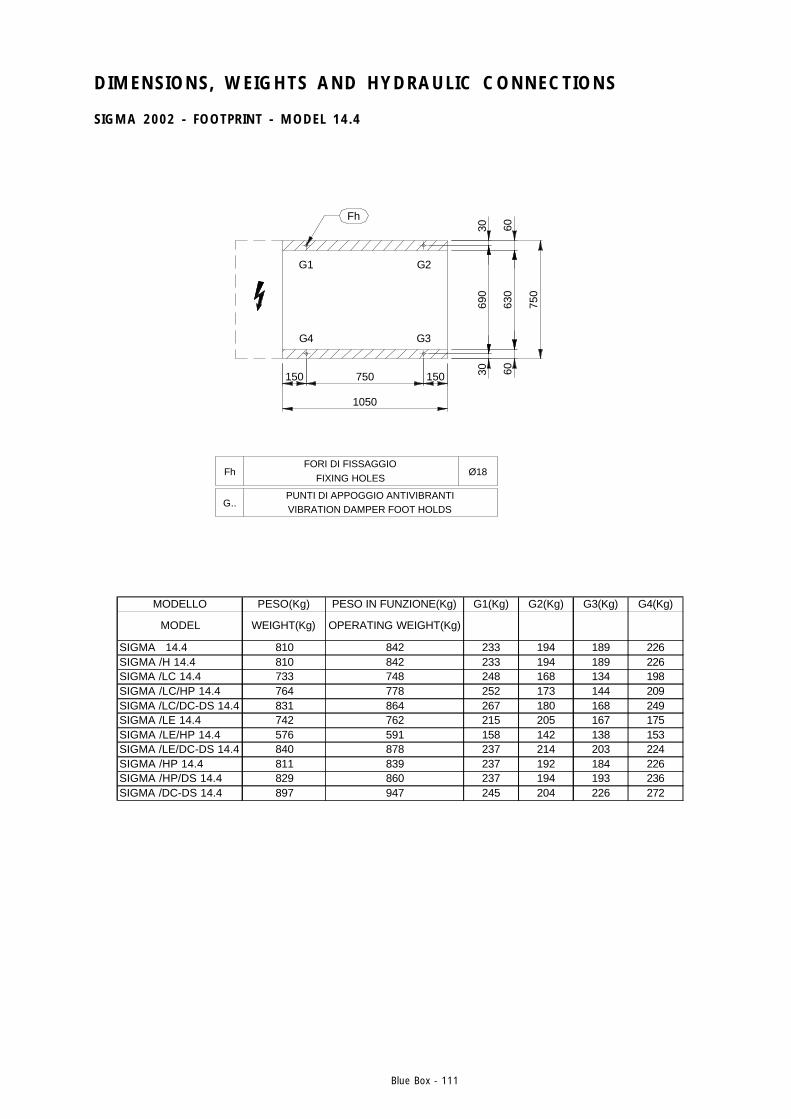
Blue Box - 111
DIMENSIONS, WEIGHTS AND HYDRAULIC CONNECTIONS
SIGMA 2002 - FOOTPRINT - MODEL 14.4
MODELLO PESO(Kg) PESO IN FUNZIONE(Kg) G1(Kg) G2(Kg) G3(Kg) G4(Kg)
MODEL WEIGHT(Kg) OPERATING WEIGHT(Kg)
SIGMA 14.4 810 842 233 194 189 226SIGMA /H 14.4 810 842 233 194 189 226SIGMA /LC 14.4 733 748 248 168 134 198SIGMA /LC/HP 14.4 764 778 252 173 144 209SIGMA /LC/DC-DS 14.4 831 864 267 180 168 249SIGMA /LE 14.4 742 762 215 205 167 175SIGMA /LE/HP 14.4 576 591 158 142 138 153SIGMA /LE/DC-DS 14.4 840 878 237 214 203 224SIGMA /HP 14.4 811 839 237 192 184 226SIGMA /HP/DS 14.4 829 860 237 194 193 236SIGMA /DC-DS 14.4 897 947 245 204 226 272
Ø18
G1 G2
G4 G3
Fh
FhFORI DI FISSAGGIO
FIXING HOLES
G..PUNTI DI APPOGGIO ANTIVIBRANTIVIBRATION DAMPER FOOT HOLDS
1050
750
6063
06030
690
30150750150
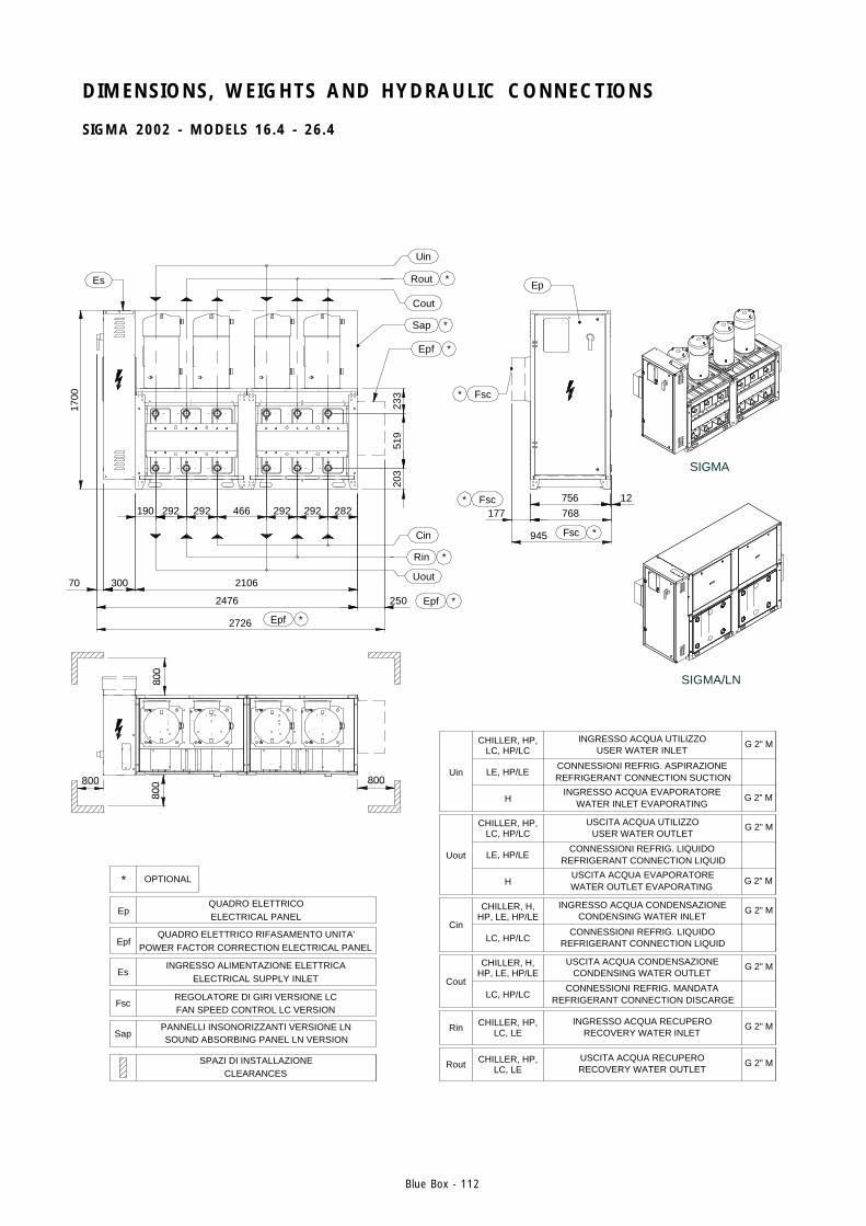
Blue Box - 112
DIMENSIONS, WEIGHTS AND HYDRAULIC CONNECTIONS
SIGMA 2002 - MODELS 16.4 - 26.4
800
300
190
Es
519
292
*Epf
466292 292
250
203
282
233
Uin
G 2" MCHILLER, HP, LC, HP/LC
LE, HP/LE
H G 2" MWATER INLET EVAPORATING
REFRIGERANT CONNECTION SUCTION
USER WATER INLET
INGRESSO ACQUA EVAPORATORE
CONNESSIONI REFRIG. ASPIRAZIONE
INGRESSO ACQUA UTILIZZO
Rout G 2" MCHILLER, HP, LC, LE RECOVERY WATER OUTLET
USCITA ACQUA RECUPERO
Rin G 2" MCHILLER, HP, LC, LE RECOVERY WATER INLET
INGRESSO ACQUA RECUPERO
Cout
G 2" MCHILLER, H, HP, LE, HP/LE
LC, HP/LC REFRIGERANT CONNECTION DISCARGE
CONDENSING WATER OUTLET
CONNESSIONI REFRIG. MANDATA
USCITA ACQUA CONDENSAZIONE
Cin
G 2" MCHILLER, H,HP, LE, HP/LE
LC, HP/LC REFRIGERANT CONNECTION LIQUID
CONDENSING WATER INLET
CONNESSIONI REFRIG. LIQUIDO
INGRESSO ACQUA CONDENSAZIONE
Uout
G 2" MCHILLER, HP, LC, HP/LC
LE, HP/LE
H G 2" MWATER OUTLET EVAPORATING
REFRIGERANT CONNECTION LIQUID
USER WATER OUTLET
USCITA ACQUA EVAPORATORE
CONNESSIONI REFRIG. LIQUIDO
USCITA ACQUA UTILIZZO
Epf
Epf
Sap
Uin
Rout
Cout
Cin
Rin
Uout
1700
70
* OPTIONAL
SapPANNELLI INSONORIZZANTI VERSIONE LNSOUND ABSORBING PANEL LN VERSION
EpQUADRO ELETTRICOELECTRICAL PANEL
FscREGOLATORE DI GIRI VERSIONE LCFAN SPEED CONTROL LC VERSION
SPAZI DI INSTALLAZIONECLEARANCES
EsINGRESSO ALIMENTAZIONE ELETTRICA
ELECTRICAL SUPPLY INLET
EpfQUADRO ELETTRICO RIFASAMENTO UNITA'
POWER FACTOR CORRECTION ELECTRICAL PANEL
800800 800
2726
2476
2106
292
945
177 768756
*
Fsc
*
* 12
Fsc *
Ep
Fsc
*
*
*
*
SIGMA/LN
SIGMA

Blue Box - 113
DIMENSIONS, WEIGHTS AND HYDRAULIC CONNECTIONS
SIGMA 2002 - FOOTPRINT - MODELS 16.4 - 26.4
150 750 300 750 150
2100
6063
06030
690
30
750Fh
FORI DI FISSAGGIOFIXING HOLES
G..PUNTI DI APPOGGIO ANTIVIBRANTIVIBRATION DAMPER FOOT HOLDS
G1 G1 G2 G2
G4 G4 G3 G3
FhØ18
IMPRONTA A TERRA / FOOT PRINT
MODELLO PESO(Kg) PESO IN FUNZIONE(Kg) G1(Kg) G2(Kg) G3(Kg) G4(Kg)MODEL WEIGHT(Kg) OPERATING WEIGHT(Kg)
SIGMA 16.4 928 966 147 89 93 154SIGMA 18.4 1069 1116 175 100 103 180SIGMA 20.4 1210 1262 189 125 126 191SIGMA 24.4 1226 1286 191 127 130 195SIGMA 26.4 1270 1340 194 131 139 206SIGMA/H 16.4 928 966 147 89 93 154SIGMA/H 18.4 1069 1116 175 100 103 180SIGMA/H 20.4 1210 1262 189 125 126 191SIGMA/H 24.4 1226 1286 191 127 130 195SIGMA/H 26.4 1270 1340 194 131 139 206SIGMA/LC 16.4 843 860 141 80 76 133SIGMA/LC 18.4 975 1000 165 95 87 153SIGMA/LC 20.4 1098 1124 184 112 100 166SIGMA/LC 24.4 1106 1136 186 112 101 169SIGMA/LC 26.4 1130 1162 189 112 104 176SIGMA/LC/HP 16.4 878 898 146 85 80 138SIGMA/LC/HP 18.4 1023 1048 172 101 93 158SIGMA/LC/HP 20.4 1146 1174 191 118 106 172SIGMA/LC/HP 24.4 1154 1182 192 118 107 174SIGMA/LC/HP 26.4 1314 1376 193 142 150 203SIGMA/LC/DC-DS 16.4 953 992 156 92 92 156SIGMA/LC/DC-DS 18.4 1094 1142 181 107 105 178SIGMA/LC/DC-DS 20.4 1235 1288 201 126 122 195SIGMA/LC/DC-DS 24.4 1251 1310 203 127 125 200SIGMA/LC/DC-DS 26.4 1295 1362 208 129 132 212SIGMA/LE 16.4 851 876 136 88 84 130SIGMA/LE 18.4 974 998 161 98 91 149SIGMA/LE 20.4 1106 1136 173 124 113 158SIGMA/LE 24.4 1114 1148 173 126 116 159SIGMA/LE 26.4 1134 1176 173 130 122 163SIGMA/LE/HP 16.4 878 898 141 90 85 133SIGMA/LE/HP 18.4 1023 1046 168 104 96 155SIGMA/LE/HP 20.4 1146 1170 180 128 115 162SIGMA/LE/HP 24.4 1154 1184 180 130 118 164SIGMA/LE/HP 26.4 1178 1212 180 134 125 167SIGMA/LE/DC-DS 16.4 960 1004 151 99 100 152SIGMA/LE/DC-DS 18.4 1093 1142 177 111 109 174SIGMA/LE/DC-DS 20.4 1243 1302 191 138 135 187SIGMA/LE/DC-DS 24.4 1259 1322 191 140 140 190SIGMA/LE/DC-DS 26.4 1299 1374 193 146 150 198SIGMA/HP 16.4 930 964 149 88 91 154SIGMA/HP 18.4 1080 1124 177 101 103 181SIGMA/HP 20.4 1212 1260 191 124 124 191SIGMA/HP 24.4 1228 1282 192 126 128 195SIGMA/HP 26.4 1276 1338 195 130 138 206SIGMA/HP/DS 16.4 985 1030 150 92 104 169SIGMA/HP/DS 18.4 1135 1190 178 105 116 196SIGMA/HP/DS 20.4 1275 1338 193 129 139 208SIGMA/HP/DS 24.4 1291 1356 194 130 142 212SIGMA/HP/DS 26.4 1339 1414 197 135 152 223SIGMA/DC-DS 16.4 1037 1096 162 100 109 177SIGMA/DC-DS 18.4 1188 1258 191 112 121 205SIGMA/DC-DS 20.4 1347 1428 207 139 148 220SIGMA/DC-DS 24.4 1371 1460 208 142 154 226SIGMA/DC-DS 26.4 1435 1540 213 148 167 242
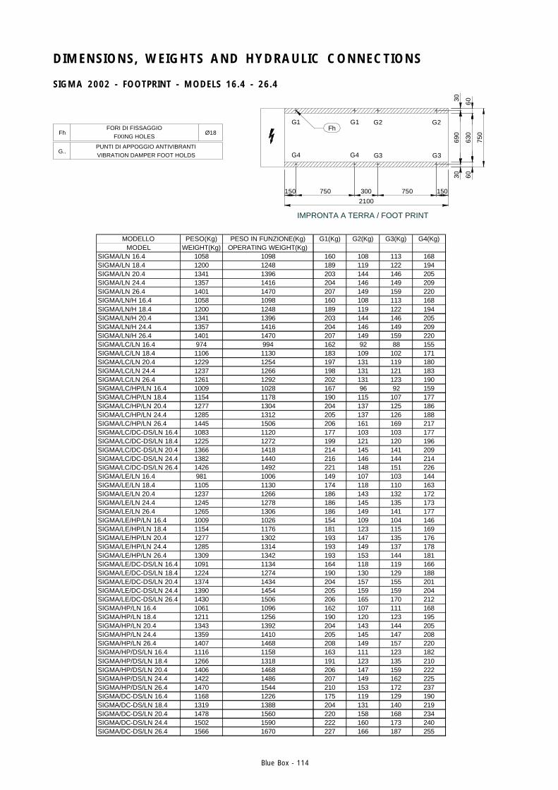
Blue Box - 114
150 750 300 750 150
2100
6063
06030
690
30
750Fh
FORI DI FISSAGGIOFIXING HOLES
G..PUNTI DI APPOGGIO ANTIVIBRANTIVIBRATION DAMPER FOOT HOLDS
G1 G1 G2 G2
G4 G4 G3 G3
FhØ18
IMPRONTA A TERRA / FOOT PRINT
MODELLO PESO(Kg) PESO IN FUNZIONE(Kg) G1(Kg) G2(Kg) G3(Kg) G4(Kg)MODEL WEIGHT(Kg) OPERATING WEIGHT(Kg)
SIGMA/LN 16.4 1058 1098 160 108 113 168SIGMA/LN 18.4 1200 1248 189 119 122 194SIGMA/LN 20.4 1341 1396 203 144 146 205SIGMA/LN 24.4 1357 1416 204 146 149 209SIGMA/LN 26.4 1401 1470 207 149 159 220SIGMA/LN/H 16.4 1058 1098 160 108 113 168SIGMA/LN/H 18.4 1200 1248 189 119 122 194SIGMA/LN/H 20.4 1341 1396 203 144 146 205SIGMA/LN/H 24.4 1357 1416 204 146 149 209SIGMA/LN/H 26.4 1401 1470 207 149 159 220SIGMA/LC/LN 16.4 974 994 162 92 88 155SIGMA/LC/LN 18.4 1106 1130 183 109 102 171SIGMA/LC/LN 20.4 1229 1254 197 131 119 180SIGMA/LC/LN 24.4 1237 1266 198 131 121 183SIGMA/LC/LN 26.4 1261 1292 202 131 123 190SIGMA/LC/HP/LN 16.4 1009 1028 167 96 92 159SIGMA/LC/HP/LN 18.4 1154 1178 190 115 107 177SIGMA/LC/HP/LN 20.4 1277 1304 204 137 125 186SIGMA/LC/HP/LN 24.4 1285 1312 205 137 126 188SIGMA/LC/HP/LN 26.4 1445 1506 206 161 169 217SIGMA/LC/DC-DS/LN 16.4 1083 1120 177 103 103 177SIGMA/LC/DC-DS/LN 18.4 1225 1272 199 121 120 196SIGMA/LC/DC-DS/LN 20.4 1366 1418 214 145 141 209SIGMA/LC/DC-DS/LN 24.4 1382 1440 216 146 144 214SIGMA/LC/DC-DS/LN 26.4 1426 1492 221 148 151 226SIGMA/LE/LN 16.4 981 1006 149 107 103 144SIGMA/LE/LN 18.4 1105 1130 174 118 110 163SIGMA/LE/LN 20.4 1237 1266 186 143 132 172SIGMA/LE/LN 24.4 1245 1278 186 145 135 173SIGMA/LE/LN 26.4 1265 1306 186 149 141 177SIGMA/LE/HP/LN 16.4 1009 1026 154 109 104 146SIGMA/LE/HP/LN 18.4 1154 1176 181 123 115 169SIGMA/LE/HP/LN 20.4 1277 1302 193 147 135 176SIGMA/LE/HP/LN 24.4 1285 1314 193 149 137 178SIGMA/LE/HP/LN 26.4 1309 1342 193 153 144 181SIGMA/LE/DC-DS/LN 16.4 1091 1134 164 118 119 166SIGMA/LE/DC-DS/LN 18.4 1224 1274 190 130 129 188SIGMA/LE/DC-DS/LN 20.4 1374 1434 204 157 155 201SIGMA/LE/DC-DS/LN 24.4 1390 1454 205 159 159 204SIGMA/LE/DC-DS/LN 26.4 1430 1506 206 165 170 212SIGMA/HP/LN 16.4 1061 1096 162 107 111 168SIGMA/HP/LN 18.4 1211 1256 190 120 123 195SIGMA/HP/LN 20.4 1343 1392 204 143 144 205SIGMA/HP/LN 24.4 1359 1410 205 145 147 208SIGMA/HP/LN 26.4 1407 1468 208 149 157 220SIGMA/HP/DS/LN 16.4 1116 1158 163 111 123 182SIGMA/HP/DS/LN 18.4 1266 1318 191 123 135 210SIGMA/HP/DS/LN 20.4 1406 1468 206 147 159 222SIGMA/HP/DS/LN 24.4 1422 1486 207 149 162 225SIGMA/HP/DS/LN 26.4 1470 1544 210 153 172 237SIGMA/DC-DS/LN 16.4 1168 1226 175 119 129 190SIGMA/DC-DS/LN 18.4 1319 1388 204 131 140 219SIGMA/DC-DS/LN 20.4 1478 1560 220 158 168 234SIGMA/DC-DS/LN 24.4 1502 1590 222 160 173 240SIGMA/DC-DS/LN 26.4 1566 1670 227 166 187 255
DIMENSIONS, WEIGHTS AND HYDRAULIC CONNECTIONS
SIGMA 2002 - FOOTPRINT - MODELS 16.4 - 26.4
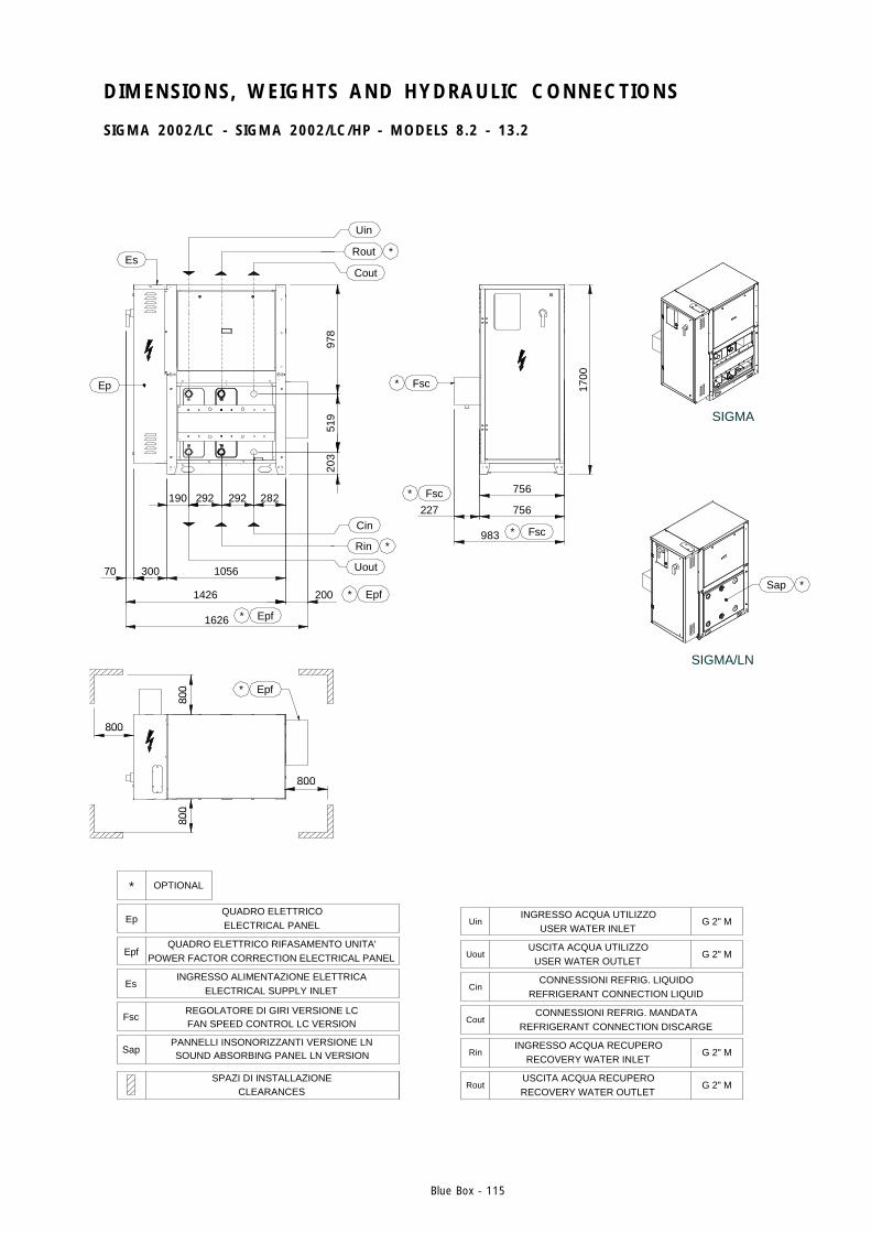
Blue Box - 115
DIMENSIONS, WEIGHTS AND HYDRAULIC CONNECTIONS
SIGMA 2002/LC - SIGMA 2002/LC/HP - MODELS 8.2 - 13.2
227Fsc
Fsc
800
* OPTIONAL
SapPANNELLI INSONORIZZANTI VERSIONE LNSOUND ABSORBING PANEL LN VERSION
EpQUADRO ELETTRICOELECTRICAL PANEL
FscREGOLATORE DI GIRI VERSIONE LCFAN SPEED CONTROL LC VERSION
SPAZI DI INSTALLAZIONECLEARANCES
EsINGRESSO ALIMENTAZIONE ELETTRICA
ELECTRICAL SUPPLY INLET
EpfQUADRO ELETTRICO RIFASAMENTO UNITA'
POWER FACTOR CORRECTION ELECTRICAL PANEL
800
1626
1426
800
1056
190
70
800
300
Ep
Es
519
203
200
*
* Epf
Epf
292292 282
Epf*
Cin
Rin
Uout
*
*
978
Uin
Rout
Cout
*
*
G 2" M
USER WATER OUTLETUSCITA ACQUA UTILIZZO
G 2" MUout
REFRIGERANT CONNECTION LIQUIDCONNESSIONI REFRIG. LIQUIDO
Cin
REFRIGERANT CONNECTION DISCARGECONNESSIONI REFRIG. MANDATA
Cout
G 2" M
RECOVERY WATER OUTLETUSCITA ACQUA RECUPERO
Rout G 2" M
983
756
1700
756
Fsc*
*Sap
SIGMA/LN
SIGMA
RinINGRESSO ACQUA RECUPERO
RECOVERY WATER INLET
UinINGRESSO ACQUA UTILIZZO
USER WATER INLET
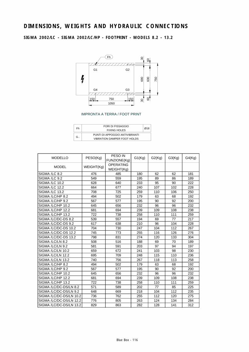
Blue Box - 116
DIMENSIONS, WEIGHTS AND HYDRAULIC CONNECTIONS
SIGMA 2002/LC - SIGMA 2002/LC/HP - FOOTPRINT - MODELS 8.2 - 13.2
MODELLO PESO(Kg)PESO IN
FUNZIONE(Kg)G1(Kg) G2(Kg) G3(Kg) G4(Kg)
MODEL WEIGHT(Kg)OPERATING WEIGHT(Kg)
SIGMA /LC 8.2 476 485 180 62 62 181SIGMA /LC 9.2 549 559 195 89 86 189SIGMA /LC 10.2 628 640 233 95 90 222SIGMA /LC 12.2 664 677 240 107 102 228SIGMA /LC 13.2 708 725 259 110 106 250SIGMA /LC/HP 8.2 494 502 179 63 68 192SIGMA /LC/HP 9.2 567 577 195 90 92 200SIGMA /LC/HP 10.2 645 656 232 96 96 232SIGMA /LC/HP 12.2 681 694 239 109 108 238SIGMA /LC/HP 13.2 722 738 258 110 111 259SIGMA /LC/DC-DS 8.2 539 557 194 69 77 217SIGMA /LC/DC-DS 9.2 617 638 210 96 104 228SIGMA /LC/DC-DS 10.2 704 730 247 104 112 267SIGMA /LC/DC-DS 12.2 745 773 255 116 126 276SIGMA /LC/DC-DS 13.2 798 831 274 120 133 304SIGMA /LC/LN 8.2 508 516 188 69 70 189SIGMA /LC/LN 9.2 581 591 203 97 94 197SIGMA /LC/LN 10.2 659 672 241 103 98 230SIGMA /LC/LN 12.2 695 709 248 115 110 236SIGMA /LC/LN 13.2 740 756 267 118 113 258SIGMA /LC/HP 8.2 494 502 179 63 68 192SIGMA /LC/HP 9.2 567 577 195 90 92 200SIGMA /LC/HP 10.2 645 656 232 96 96 232SIGMA /LC/HP 12.2 681 694 239 109 108 238SIGMA /LC/HP 13.2 722 738 258 110 111 259SIGMA /LC/DC-DS/LN 8.2 571 589 202 77 85 225SIGMA /LC/DC-DS/LN 9.2 648 669 218 104 112 235SIGMA /LC/DC-DS/LN 10.2 736 762 255 112 120 275SIGMA /LC/DC-DS/LN 12.2 776 805 263 124 134 284SIGMA /LC/DC-DS/LN 13.2 829 863 282 128 141 312
G..PUNTI DI APPOGGIO ANTIVIBRANTIVIBRATION DAMPER FOOT HOLDS
FhFORI DI FISSAGGIO
FIXING HOLES
1050750
IMPRONTA A TERRA / FOOT PRINT
150
Fh
G4
G1
30
150 60
750
690
30 6063
0
G3
G2
Ø18

BLUE BOX srl
is an associate company of
BLUE BOX GROUP
BLUE BOX GROUP
on the internet
Web Pageswww.blueboxgroup.it
BLUE BOX srl
Via E. Mattei, 2035028 Piove di Sacco PD ItalyTel. +39.049.9716300Fax +39.049.9704105
Manual 101130A02 - Issue 12.02 - Replaces 09.98All data in this manual is subject to change without prior notice
Is a
mem
ber
of P
iove
Clim
a Sy
ndac
ate