dc-6 operation manual basic ce v1.1
TRANSCRIPT

7/16/2019 DC-6 Operation Manual Basic CE V1.1
http://slidepdf.com/reader/full/dc-6-operation-manual-basic-ce-v11 1/149
DC-6
Diagnostic Ultrasound System
Operation Manual
[Basic Volume]

7/16/2019 DC-6 Operation Manual Basic CE V1.1
http://slidepdf.com/reader/full/dc-6-operation-manual-basic-ce-v11 2/149

7/16/2019 DC-6 Operation Manual Basic CE V1.1
http://slidepdf.com/reader/full/dc-6-operation-manual-basic-ce-v11 3/149
I-1
© 2006 Shenzhen Mindray Bio-medical Electronics Co., Ltd. All rights Reserved.
Product Information
Product Name: Diagnostic Ultrasound System
Model: DC-6
Issued date of this manual: 2006-12
Version: 1.1.
Intellectual Property Statement
SHENZHEN MINDRAY BIO-MEDICAL ELECTRONICS CO., LTD. (hereinafter called
Mindray) owns the intellectual property rights to this Mindray product and this manual. This
manual may refer to information protected by copyrights or patents and does not convey any
license under the patent rights of Mindray, nor the rights of others. Mindray does not assume
any liability arising out of any infringements of patents or other rights of third parties.
Mindray intends to maintain the contents of this manual as confidential information.
Disclosure of the information in this manual in any manner without the written permission of
Mindray is strictly forbidden.
Release, amendment, reproduction, distribution, rent, adaptation or translation of this
manual, in any manner whatsoever without the written permission of Mindray, is strictly
forbidden.
, , , , are the registered trademarks or
trademarks owned by Mindray in China and other countries. All other trademarks that
appear in this manual are used only for editorial purposes without the intention of improperly
using them. They are the property of their respective owners.

7/16/2019 DC-6 Operation Manual Basic CE V1.1
http://slidepdf.com/reader/full/dc-6-operation-manual-basic-ce-v11 4/149
I-2
Responsibility on the Manufacturer Party
Contents of this manual are subject to changes without prior notice.
All information contained in this manual is believed to be correct. Mindray shall not be liable
for errors contained herein nor for incidental or consequential damages in connection with
the furnishing, performance, or use of this manual.
Mindray is responsible for safety, reliability and performance of this product only in the
condition that:
• all installation operations, expansions, changes, modifications and repairs of this product
are conducted by Mindray authorized personnel;
• the electrical installation of the relevant room complies with the applicable national and
local requirements;
• the product is used in accordance with the instructions for use.
WARNING: It is impor tant for the hospital or organization that employs this
equipment to carry out a reasonable service/maintenance plan.
Neglect of this may result in machine breakdown or injury o f
human health.
Warranty
THIS WARRANTY IS EXCLUSIVE AND IS IN LIEU OF ALL OTHER WARRANTIES,
EXPRESSED OR IMPLIED, INCLUDING WARRANTIES OF MERCHANTABILITY OR
FITNESS FOR ANY PARTICULAR PURPOSE.
Exemptions
Mindray's obligation or liability under this warranty does not include any transportation or other charges or liability for direct, indirect or consequential damages or delay resulting from
the improper use or application of the product or the use of parts or accessories not
approved by Mindray or repairs by people other than Mindray authorized personnel.
This warranty shall not extend to:
z any Mindray product which has been subjected to misuse, negligence or accident;
z any Mindray product from which Mindray's original serial number tag or product
identification markings have been altered or removed;
z any product of any other manufacturer.

7/16/2019 DC-6 Operation Manual Basic CE V1.1
http://slidepdf.com/reader/full/dc-6-operation-manual-basic-ce-v11 5/149
I-3
Return Policy
Return ProcedureIn the event that it becomes necessary to return this product or part of this product to
Mindray, the following procedure should be followed:
1. Obtain return authorization: Contact the Mindray Service Department and obtain a
Customer Service Authorization (Mindray) number. The Mindray number must appear
on the outside of the shipping container. Returned shipments will not be accepted if the
Mindray number is not clearly visible. Please provide the model number, serial number,
and a brief description of the reason for return.
2. Freight policy: The customer is responsible for freight charges when this product is
shipped to Mindray for service (this includes customs charges).
3. Return address: Please send the part(s) or equipment to the address offered by
Customer Service department
Company Contact
Manufacturer: Shenzhen Mindray Bio-Medical Electronics Co., Ltd.
Address: Mindray Building, Keji 12th Road South, Hi-tech Industrial
Park, Nanshan, Shenzhen,518057, P.R.China
Phone: +86 755 26582479 26582888
Fax: +86 755 26582934 26582500
EC-Representative: Shanghai International Holding Corp. GmbH(Europe)
Address: Eiffestrasse 80, 20537 Hamburg Germany
Phone: 0049-40-2513175
Fax: 0049-40-255726

7/16/2019 DC-6 Operation Manual Basic CE V1.1
http://slidepdf.com/reader/full/dc-6-operation-manual-basic-ce-v11 6/149
I-4
Important Information
1. The responsibility for maintenance and management of the product after delivery
resides with the customer who has purchased the product.
2. The warranty does not cover the following items, even during the warranty period:
(1) Damage or loss due to misuse or abuse.
(2) Damage or loss caused by Acts of God such as fires, earthquakes, floods,
lightning, etc.
(3) Damage or loss caused by failure to meet the specified conditions for this system,
such as inadequate power supply, improper installation, or unacceptable
environmental conditions.
(4) Damage or loss due to use outside the territory in which the system was originally
sold.
(5) Damage or loss involving system purchased from a source other than Mindray or
its authorized agents.
3. This system shall not be used by persons other than fully qualified and certified medical
personnel.
4. Do not make changes or modifications to the software or hardware of this product.
5. In no event shall Mindray be liable for problems, damage, or loss caused by relocation,
modification, or repair performed by personnel other than those designated by Mindray.
6. The purpose of this system is to provide physicians with data for clinical diagnosis.
The responsibility for diagnostic procedures lies with the physicians involved. Mindray
shall not be liable for the results of diagnostic procedures.
7. Important data must be backed up on external recording media such as clinical records,
notebooks etc.
8. Mindray shall not be liable for loss of data stored in the memory of this system caused
by operator error or accidents.
9. This manual contains Warnings regarding foreseeable potential dangers. Be alert at all
times to dangers other than those indicated. Mindray shall not be liable for damage or
loss that results from negligence or from ignoring the precautions and operating
instructions contained in this operation manual.
10. On the occasion of change of the administrator or manager for this system, be sure to
hand over this operation manual.

7/16/2019 DC-6 Operation Manual Basic CE V1.1
http://slidepdf.com/reader/full/dc-6-operation-manual-basic-ce-v11 7/149
I-5
Introduction
This operation manual describes the operating procedures for DC-6 diagnostic ultrasound
system. To ensure safe and correct operation of the system, carefully read and understand
the manual before operating the system.
1. Notation Conventions
In this operation manual, the following words are used in addition to the signal words related
to the safety precautions (refer to "Safety Precautions"). Please read this operation manual
before using the system.
NOTE: Indicates information of interest to users of this system as to exceptional
conditions or operating procedures.
CAUTION: In U.S.A. federal Law restric ts this device to be sale by or on the
order of a physician.
CAUTION: The DC-6 Diagnostic Ultrasound system is not intended for
ophthalmic use. Its use in this cl inical specialty is
contraindicated.

7/16/2019 DC-6 Operation Manual Basic CE V1.1
http://slidepdf.com/reader/full/dc-6-operation-manual-basic-ce-v11 8/149
I-6
2. Operation Manuals
The organization of the documents supplied with this system is shown below:
Main unit operation manuals
Transducer operation manuals
Describe detailed system information on preparation,operating procedures, maintenance checks, and
functions.
Describe the operating and sterilization procedures
for transducers.
NOTE: For practical applications, the following manuals are available:
(1) (Advanced Volume)
(2) (Acoustic Output Data)
3. Interface in this Operation Manual
Depending on the software version and configuration of each system, interfaces or menus
may appear different from those shown in the manuals. Please refer to the displays of the
system you purchased.

7/16/2019 DC-6 Operation Manual Basic CE V1.1
http://slidepdf.com/reader/full/dc-6-operation-manual-basic-ce-v11 9/149
S-1
Safety Precautions
1. Meaning of Signal Words
In this operation manual, the signal words DANGER, WARNING,
CAUTION and NOTE are used regarding safety and other important instructions.
The signal words and their meanings are defined as follows. Please understand their
meanings clearly before reading this manual.
Signal word Meaning
DANGER Indicates an imminently hazardous situation that, if not avoided,
will result in death or serious injury.
WARNING Indicates a potentially hazardous situation that, if not avoided,
could result in death or serious injury.
CAUTION Indicates a potentially hazardous situation that, if not avoided,
may result in minor or moderate injury.
NOTE Indicates a potentially hazardous situation that, if not avoided, may
result in property damage.
2. Meaning of Safety Symbols
Symbol Description
Type-BF applied part
The ultrasound transducers connected to this system are Type-BF
applied parts.
The ECG module connected to this system is also a Type-BF appliedpart.
"Attention" indicates the points requiring attention. Be sure to read the
operation manual concerning these points before using the equipment.

7/16/2019 DC-6 Operation Manual Basic CE V1.1
http://slidepdf.com/reader/full/dc-6-operation-manual-basic-ce-v11 10/149
S-2
3. Safety Precautions
Please observe the following precautions to ensure patient and operator safety when using
this system.
DANGER: Do not use flammable gasses such as anesthetic gas, oxygen or
hydrogen, or flammable liquids such as ethanol, near this product,
because there is danger of explosion.
WARNING:
1. Do connect the plug of this equipment to the wall receptacle, and
the plug must meet the ratings indicated on the rating nameplate.
Using an adapter or multi-functional receptacle may affect the
system grounding performance and thus causing the leakage
current to exceed safety requirements.
In addition, do connect the video printer to the auxiliary power
socket of this system. And use the printing cable provided by this
system to connect the printer. Otherwise, it may cause electric
shock.
2.Be sure to connect the potential-equalization lead wire before
inserting the equipment power plug into the receptacle. Also, be
sure to remove the equipment power plug from the receptacle
before disconnecting the wire to avoid electric shock.
3.Connect the earth conductor only before turning ON the system.
Disconnect the grounding cable only after turning OFF the system.
Otherwise, electric shock may result.
4.
For the connection of power and grounding, follow the appropriateprocedures described in this operation manual. Otherwise, there is
risk of electric shock. Do not connect the grounding cable to a gas
pipe or water pipe, otherwise functional grounding may not be
effective or there may be risk of a gas explosion.
5.Before cleaning the system, be sure to disconnect the power cable
from the outlet. If the system is defective, there is risk of electric
shock.

7/16/2019 DC-6 Operation Manual Basic CE V1.1
http://slidepdf.com/reader/full/dc-6-operation-manual-basic-ce-v11 11/149
S-3
6.No waterproof device is applied to this equipment. Do not use this
equipment in any place with the poss ibilit y of w ater ingress. There
is risk of electric shock if any water is sprayed on or into the
equipment. If carelessly spray any water onto the equipment,
contact the Mindray sales offi ce, customer service department or
representative.
7.Use the transducer carefully. In case that the body contacts the
scratched transducer surface, immediately stop us ing the
transducer and contact the Mindray sales off ice, customer service
department or representative. There is risk of electric shock if using
the scratched transducer.
8.Be careful not to let the patient contact the live parts of the
ultrasound equipment or other devices, such as signal I/O ports. If the ultrasound equipment is defective, there is risk of electric
shock.
9. Do not use the transducers other than those specified by Mindray.
Otherwise, the equipment and the transducer may be damaged,
causing an accident such as a fire in the worst case.
10. Do not subject the transducers to knocks. Use of defective
transducers may cause an electric shock.
11. Do not open the shell or f ront panel. If you open the shell when thesystem is powered on, there may be a short circuit or electric
shock.
12. Do not use this system with using equipment at the same time such
as an electrosurgical unit, high-frequency therapy equipment, or a
defibrillator, etc. otherwise it may result in electric shock to the
patient.
13. Use only the ECG leads provided with the ECG module, otherwise it
may result in electric shock.
14. If this system needs to be moved, please hold the handle. If other
parts of the system are held, it may cause damage due to the
abnormal force. Do not push the system from the left/right side;
otherwise it may be toppled over.

7/16/2019 DC-6 Operation Manual Basic CE V1.1
http://slidepdf.com/reader/full/dc-6-operation-manual-basic-ce-v11 12/149
S-4
15. Accessory equipment connected to the analogue and d igital
interfaces must be complied with the relevant IEC standards (e.g.,
IEC 60950 Safety of information technology Equipment Standard
and IEC 60601-1 Medical Equipment standard). Furthermore all
configurations should comply with the standard IEC60601-1-1. Any
person, who connects additional equipment to the signal input or
output ports and configures a medical system, is responsible for
ensuring that the system complies with the requirements of
IEC60601-1-1. If you have any problem, consult the technical
services department o f your local representative.
16. Prolonged and repeated use of keyboards can result in hand or arm
nerve disorders for some individuals. Observe the local safety or
health regulations concerning the keyboard use.
CAUTION: 1.Precautions concerning clinical examination techniques:
(1) This system must be used only by qualified professionals.
(2) This operation manual does not describe clinical
examination techniques. Selection of the proper clinical
examination technique must be based on specialized
training and clinical experience.
2.Malfunctions due to radiowaves:
(1) Use of radiowave-emitting devices in the proximity of this
medical electronic system may interfere with its operation.
Do not b ring or use devices that generate radio waves, such
as cellular telephones, transceivers, and radio controlled
toys, in the room where the system is installed.
(2) If a person brings a device that generates radio waves near
the system, ask him/her to immediately turn OFF the device.
3.Precautions concerning installation and movement of the sys tem:
(1) Ensure to install the equipment horizontally and lock up the
casters securely. Otherwise, it may move to cause injury .
(2) Do not move the equipment from its sides; otherwise it may
be toppled over and may injure people.
(3) When you move the equipment on a slope, it shall be moved
slowly by two people; otherwise it may happen to slide and
severely injure people.
(4) Do not sit on the equipment, because it may move and makepeople lose balance and fall.

7/16/2019 DC-6 Operation Manual Basic CE V1.1
http://slidepdf.com/reader/full/dc-6-operation-manual-basic-ce-v11 13/149
S-5
(5) Dot not place any object on the monitor, because it may fall
and injure people.
(6) Fasten the peripheral devices before moving the equipment.
Otherwise, the peripheral devices may fall and injure people.
(7) When moving the equipment on steps, you shall prevent it
from being toppled.
4.Do not v ibrate the equipment excessively (when moving the
equipment); otherwise the mechanical parts (such as casters) may
be damaged. If the equipment is o ften moved on a bumpy floor,
contact the Mindray sales offi ce, customer service department or
representative.
5. Do not connect this system to outlets with the same circuit
breakers and fuses that cont rol the current of devices such aslife-support systems. If this system malfunctions and generates
an overcurrent, or when there is an instantaneous current at power
ON, the circuit breakers and fuses of the building’s supply circui t
may be tripped.
6. Always keep the machine dry. Avoid transporting th is machine
quickly from the cold place to the warm place; otherwise
condensation or water drops may be formed, causing short circui t.
7.If the circuit breaker is tripped, it indicates that the machine or the
peripheral devices have problems. In these cases, you cannot repair
by yourself but should contact the Mindray sales office, customer
service department or representative.
8.There is no risk of high-temperature burns during routine
ultrasound examinations, even if, due to environment temperature
and exam modes, the surface temperature of the transducer exceeds
the body temperature of the patient. To prevent high-temperature
burns, do not apply the transducer to the same region on the patient
for a long time. Apply the transducer only for as long as required
time for diagnosis.
9.This device and its accessories are not disinfected and sterilized
when they are out of the factory, so the user shall disinfect and
sterilize transducers or biopsy brackets as per the manuals prior to
use of transducers or biopsy brackets. After the sterilization or
disinfection of accessories, chemicals must be washed out or gases
must be discharged thoroughly from the accessories. Remaining
residual chemicals or gases will not only result in damage to the
accessories but also can be harmful to human bodies.
7/16/2019 DC-6 Operation Manual Basic CE V1.1
http://slidepdf.com/reader/full/dc-6-operation-manual-basic-ce-v11 14/149
S-6
10.Before examining a new patient, press the key to delete
the patient information and data recorded in the image memory for
the previous patient. Otherwise, the new data may be confused
with the data of the previous patient.
11. Do not connect/disconnect the system and its accessories (such as
printers or recorders) without turning OFF the power; otherwise it
may cause damage of the equipment or electric shock.
12. Do not turn OFF the power supply of the system during printing,
saving, or invoking; otherwise these processes may not be
completed normally or files may be lost.
13. During operation, if the system is improperly powered off, it may
result in data damage of the hard disk or system failure.
NOTE: 1. Do not use the machine in the vicinity of strong electromagnetic field (such
as the transformer), which may affect the performance of the machine.
2. Do not use the machine in the vicinity of high-frequency radiation source,
which may affect the performance of the machine or even lead to failure.
3. To avoid damaging the machine, do not use the machine in following
environment:
(1) Locations exposed to direct sunlight;
(2) Locations subject to sudden changes in temperature;
(3) Dusty locations;
(4) Locations subject to vibration;
(5) Locations near heat generators;
(6) Locations with high humidity.
4. Turn ON the system only after the power has been OFF for more than 20
seconds. If the system is turned ON immediately after being turned OFF,
the system may malfunction.
5. Turn OFF the auxiliary power switch or stop transmission through the
『Freeze』 key before connecting or disconnecting a transducer. If a
transducer is connected or disconnected with an image displayed, the
system and/or the transducer may malfunction.

7/16/2019 DC-6 Operation Manual Basic CE V1.1
http://slidepdf.com/reader/full/dc-6-operation-manual-basic-ce-v11 15/149
S-7
6. After using the transducer, remove the ultrasound gel on it and place the
transducer on the transducer holder. Otherwise, water in the gel may enter
the acoustic lens, thus adversely affecting the performance and safety of the
transducer.
7. You can record the registration data (including the hospital data and patient
data). To ensure the security of the data, be sure to back up the data on
external storage media. Data stored in the equipment may be lost due to
improper operation or an accident.
8. Do not apply external force to the control panel (e.g. leaning against it).
Otherwise it may damage the system.
9. If the system is used in a small room, the room temperature may rise.
Therefore, proper ventilation shall be provided.
10. When disposing the system or any part of it, contact your Mindray
representative. Do not dispose of this system without consulting Mindray.
Mindray would bear no responsibility for damages resulting from disposal of
this system without consulting Mindray.
11. Degradation of electrical and mechanical safety characteristics (such as
generation of a leakage current or deformation/abrasion of mechanical
parts) and of image sensitivity and resolution may occur after a period of
time. To ensure normal operation of the system, it is recommended to sign a
maintenance and service agreement to prevent accidents.
12. Output power outlet in the system is used to supply power for the
recommended peripheral devices. Do not connect other devices to the
outlet, otherwise the rated output power may be exceeded and failure may
result. Maximum output power of the power outlet for peripheral devices is
350VA.
NOTE: The following definition of the WEEE label applies to EU member
states only: The use of this symbol indicates that this product should not
be treated as household waste. By ensuring that this product is disposedof correctly, you will help prevent bringing potential negative
consequences to the environment and human health. For more detailed
information with regard to returning and recycling this product, please
consult the distributor from whom you purchased the product.
* For system products, this label may be attached to the main unit only.
7/16/2019 DC-6 Operation Manual Basic CE V1.1
http://slidepdf.com/reader/full/dc-6-operation-manual-basic-ce-v11 16/149
S-8
4. Latex Alert
WARNING: Al lergic reactions in latex (natural rubber) sensit ive patients may
range from mild skin reactions (irritation) to fatal anaphylactic
shock, and may include difficulty in breathing (wheezing),
dizziness, shock, swelling of the face, hives, sneezing or itching
of the eyes (FDA Medical Alert on latex products, ” Allergic
Reactions to Latex-containing Medical Devices” , issued March
29, 1991)
Therefore, when choosing the transducer cover, we recommend that the user contact
CIVCO directly for obtaining transducer cover, pricing information, samples and local
distribution information. For CIVCO information, please contact the following:
CIVCO Medical Instruments
Tel: 1-800-445-6741
WWW.civco.com

7/16/2019 DC-6 Operation Manual Basic CE V1.1
http://slidepdf.com/reader/full/dc-6-operation-manual-basic-ce-v11 17/149
S-9
5. Warning Labels
Various warning labels are attached to this system in order to call the user's attention to
potential hazards.
The symbol on the warning labels indicates safety precautions. The warning labels
use the same signal words as those used in the operation manual.
Detailed information about the warning labels is given in the operation manual. Read
operation manual carefully before using the system.
The name, pattern and the meaning of each warning label are described as follows:
No. Label Meaning
<1> (a) CAUTION: Do not sit on the system.
(b) Before using the system, be sure to carefullyread the relevant content of this operationmanual.
(c) DANGER: The system must not be used aroundflammable gasses.
<2> (a) CAUTION: Do not place the system on a slopedsurface. Otherwise the system may slideunexpectedly, resulting in person injury or thesystem malfunction. The system should bemoved over a sloped surface by two persons toensure safty.
(b) CAUTION: The system shells must not beopened, because the high voltage inside maycause electric shock.
<3> Beware of excessive stress exerted to the system.

7/16/2019 DC-6 Operation Manual Basic CE V1.1
http://slidepdf.com/reader/full/dc-6-operation-manual-basic-ce-v11 18/149
C-1
CONTENTS
1 Overview ................................................................................................1-1
1.1 Intended Use .................................................................................................. 1-1
1.2 Model Introduction ..........................................................................................1-1
2 Product Specifications .........................................................................2-1
2.1 Image Modes .................................................................................................. 2-1
2.2 Environmental Conditions ............................................................................... 2-1
2.3 External Dimensions and Weight .................................................................... 2-1
3 System Configuration...........................................................................3-1
3.1 Standard Configuration ................................................................................... 3-1
3.2 Transducers Available..................................................................................... 3-1
3.3 Optional Units ................................................................................................. 3-2
3.4 Supported Peripheral Devices ........................................................................ 3-2
4 Introduct ion ...........................................................................................4-1
4.1 Introduction of Each Unit................................................................................. 4-1
4.2 I/O Panel......................................................................................................... 4-3
4.3 Power Panel ...................................................................................................4-4
4.4 ECG Panel...................................................................................................... 4-5
4.5 Control Panel .................................................................................................. 4-6
4.6 Symbols ........................................................................................................ 4-13
5 Placement and Connection ..................................................................5-1
5.1 Placing the System ......................................................................................... 5-1
5.2 Connecting the Power Cable and Protective Earth......................................... 5-1
5.3 Connecting/Disconnecting a Transducer ........................................................ 5-4
5.4 Connecting/Removing a USB Memory Device ............................................... 5-5
5.5 Connecting a Footswitch................................................................................. 5-6
5.6 Connecting a graph/text printer....................................................................... 5-6
6 Power ON/OFF.......................................................................................6-1
6.1 Power ON ....................................................................................................... 6-1
6.2 Restart the System ......................................................................................... 6-3
6.3 Power OFF .....................................................................................................6-3
7 Basic Screen and Operation ................................................................7-1 7.1 Basic Screen................................................................................................... 7-1

7/16/2019 DC-6 Operation Manual Basic CE V1.1
http://slidepdf.com/reader/full/dc-6-operation-manual-basic-ce-v11 19/149
C-2
7.2 Basic Operations of Dialog ............................................................................. 7-5
8 Patient Information ...............................................................................8-1
8.1 Entering/Exiting Patient Information................................................................ 8-1
8.2 Patient Information Input................................................................................. 8-2
8.3 Importing Patient Information Worklist ............................................................ 8-5
9 Exam Modes ..........................................................................................9-1
9.1 Instruction of Exam Modes ............................................................................. 9-1
9.2 Selecting Exam Modes ................................................................................... 9-2
9.3 Presetting Exam Modes.................................................................................. 9-2
10 Image Modes .......................................................................................10-1
10.1 Categories of Image Modes.......................................................................... 10-1
10.2 Switching Between Image Modes................................................................. 10-2
10.3 Image Adjustment ......................................................................................... 10-3
10.4 Image Parameter Preset............................................................................. 10-14
11 Cine Review .........................................................................................11-1
11.1 Entering/Exiting Cine Review........................................................................ 11-1
11.2 Cine Review in the B/Color Mode ................................................................. 11-2
11.3 Cine Review in the PW/M Mode ................................................................... 11-2
11.4 Linked Cine Review ...................................................................................... 11-2
11.5 Setting Region of Auto Review ..................................................................... 11-3
12 Measurements .....................................................................................12-1
12.1 Basic Operation ............................................................................................12-1
12.2 General Measurements ................................................................................ 12-2
12.3 Application Measurements............................................................................ 12-5
13 Comments ...........................................................................................13-1
13.1 Entering/Exiting Comments ..........................................................................13-1
13.2 Comment Menu ............................................................................................ 13-1 13.3 Adding Comments ........................................................................................ 13-2
13.4 Moving Comments........................................................................................ 13-5
13.5 Modifying Comments .................................................................................... 13-5
13.6 Deleting Comments ...................................................................................... 13-6
13.7 Comment Preset........................................................................................... 13-7
14 Body Marks..........................................................................................14-1
14.1 Entering/Exiting Body Mark Mode................................................................. 14-1
14.2 Categories of Body Marks............................................................................. 14-1

7/16/2019 DC-6 Operation Manual Basic CE V1.1
http://slidepdf.com/reader/full/dc-6-operation-manual-basic-ce-v11 20/149
C-3
14.3 Body Mark Menu........................................................................................... 14-2
14.4 Adding Body Marks....................................................................................... 14-3
14.5 Moving Body Marks ...................................................................................... 14-4
14.6 Deleting Body Marks..................................................................................... 14-4
14.7 Body Mark Preset ......................................................................................... 14-5
15 Patient File Management ....................................................................15-1
15.1 Image File Formats....................................................................................... 15-1
15.2 Storing Image Files ....................................................................................... 15-2
15.3 Image Review and Analysis .......................................................................... 15-3
15.4 iVision ........................................................................................................... 15-3
15.5 Search Patient .............................................................................................. 15-4
15.6 iStation.......................................................................................................... 15-5
15.7 Disk Management......................................................................................... 15-6
16 Preset ...................................................................................................16-1
16.1 Entering/Exiting Preset ................................................................................. 16-1
16.2 System Preset .............................................................................................. 16-2
16.3 Exam Mode Preset ....................................................................................... 16-3
16.4 Image Parameter Preset............................................................................... 16-3
16.5 Comment Preset........................................................................................... 16-3
16.6 Body Mark Preset ......................................................................................... 16-3
16.7 Measurement Preset ....................................................................................16-4
16.8 Preset Data................................................................................................... 16-4
16.9 Maintenance ................................................................................................. 16-4
17 Biopsy Guide .......................................................................................17-1
17.1 Entering or Exiting Biopsy Menu................................................................... 17-1
17.2 Displaying Biopsy Guide Lines ..................................................................... 17-1
17.3 Verifying the Biopsy Guide line ..................................................................... 17-2 18 ECG......................................................................................................18-1
18.1 ECG Connection........................................................................................... 18-2
18.2 Displaying ECG Signal.................................................................................. 18-2
19 VCR ......................................................................................................19-1
19.1 Record .......................................................................................................... 19-2
19.2 Replay........................................................................................................... 19-3
20 System Maintenance ..........................................................................20-1
20.1 Daily Maintenance ........................................................................................ 20-1

7/16/2019 DC-6 Operation Manual Basic CE V1.1
http://slidepdf.com/reader/full/dc-6-operation-manual-basic-ce-v11 21/149
C-4
20.2 Maintenance Checks by Service Engineer ................................................... 20-3
20.3 Consumable Parts and the Parts of Periodic Replacement .......................... 20-4
20.4 Troubleshooting ............................................................................................ 20-4
21 Acoust ic Output ..................................................................................21-1
21.1 Concerns with Bioeffects .............................................................................. 21-1
21.2 Prudent Use Statement................................................................................. 21-1
21.3 ALARA Principle (As Low As Reasonably Achievable) ................................. 21-2
21.4 MI/TI Explanation.......................................................................................... 21-2
21.5 Acoustic Power Setting................................................................................. 21-5
21.6 Acoustic Power Control................................................................................. 21-6
21.7 Acoustic Output ............................................................................................ 21-7
21.8 Measurement Uncertainty............................................................................. 21-9
21.9 References for Acoustic Power and Safety................................................... 21-9
22 Measurement Accuracy ......................................................................22-1
23 Safety Classification ...........................................................................23-1
24 Guidance and Manufacturer's Declaration .......................................24-1
Appendix A DICOM .................................................................................... A-1

7/16/2019 DC-6 Operation Manual Basic CE V1.1
http://slidepdf.com/reader/full/dc-6-operation-manual-basic-ce-v11 22/149
1-1
1Overview
1.1 Intended Use
The DC-6 Diagnostic Ultrasound System is applicable for adults, pregnant women, pediatric
patients and neonates, and it is intended for use in abdominal, cardiac, small parts (breast,
testes, thyroid, etc.), peripheral vascular, fetal, transrectal, transvaginal, pediatric,
neonatal cephalic, musculoskeletal (general and superficial), and intraoperative (liver,
gallbladder, pancreas) exams.
1.2 Model Introduction
DC – □
Model codeProduct code
NOTE: The functions described in operation manuals of this system, are not provided for all
models sold in all regions. The functions may vary depending upon the specificsystem you purchased.

7/16/2019 DC-6 Operation Manual Basic CE V1.1
http://slidepdf.com/reader/full/dc-6-operation-manual-basic-ce-v11 23/149
2-1
2Product Specifications
2.1 Image Modes
B mode
M mode
Color mode
Power mode
PW mode
2.2 Environmental Conditions
(1) Power supply
Power supply voltage : 100 to 127V~ or 220 to 240V~
Power supply frequency : 50/60Hz
Power consumption : 800VA
(2) Operating conditions
Ambient temperature : 0°C to 40°C
Relative humidity : 30% ~ 85% (no condensation)
Atmospheric pressure : 700 hPa to 1060 hPa
(3) Storage and transportation conditions
Ambient temperature : -20°C to 55°C
Relative humidity : 30% to 95% (no condensation)
Atmospheric pressure : 700 hPa to 1060 hPa
WARNING: Do not use this system in the conditions other than those
specified.
2.3 External Dimensions and Weight
External dimensions: 1390mm (height) × 790mm (length) × 480mm (width)
Weight: Approx. 132 kg.

7/16/2019 DC-6 Operation Manual Basic CE V1.1
http://slidepdf.com/reader/full/dc-6-operation-manual-basic-ce-v11 24/149
3-1
3System Configuration
3.1 Standard Configuration
(1) Main unit
(2) Monitor
(3) Accessories
(4) Transducers of standard configuration
3.2 Transducers Available
Model Type Intended Use Region Applied
3C5 Convex Gynecology, obstetrics, abdomen,pediatrics
Body surface
3C5A Convex Gynecology, obstetrics, abdomen,pediatrics
Body surface
3C1 Convex Gynecology, obstetrics, abdomen,
pediatrics, cardiology
Body surface
6CV1 Convex Gynecology, obstetrics, urology Transvaginal,transrectal
7L4 Linear Small parts, neonatal cephalic,peripheral vascular, superficialsurface, general musculoskeletal
Body surface
7L4A Linear Small parts, neonatal cephalic,peripheral vascular, superficialsurface, general musculoskeletal
Body surface
7L6 Linear Small parts, neonatal cephalic,peripheral vascular, superficial
surface, general musculoskeletal
Body surface
10L4 Linear Small parts, neonatal cephalic,peripheral vascular, superficialsurface, general musculoskeletal
Body surface
7LT4 IntraoperativeT-type
Intraoperation (liver, gallbladder,pancreas), small parts
Intraoperation,
Body surface

7/16/2019 DC-6 Operation Manual Basic CE V1.1
http://slidepdf.com/reader/full/dc-6-operation-manual-basic-ce-v11 25/149
System Configuration
3-2
3.3 Optional Units
No Name Model Remark
1 Footswitch 971-SWNOM
2 DICOM module DICOM 3.0
3 ECG module / The ECG module contains
the relevant hardware and
software, as well as ECG
leadwires.
ECG lead part number:
AHA: 0010-20-12126
IEC: 0010-20-12127
4 HPRF module /
3.4 Supported Peripheral Devices
No Name Model Recommended
1 B/W video printer Sony UP-897MD
Mitsubishi P93W
2 Color video printer Sony UP-20;
Mitsubishi CP-910E
3 Graph/text printer HP DeskJet 5652
HP DeskJet 5650
HP DeskJet 3820
HP DeskJet 1280
HP DeskJet 6548
HP DeskJet 6848
HP DeskJet 450
HP Business InkJet 1000
HP Business InkJet 1200
4 VCR recorder Sony SVO-9500MD2
WARNING:
DC-6 complies with IEC60601-1-2:2001+A1:2004, RF emission meets the requirements
of CISPR11 Class B. In a domestic environment the customer or the user of DC-6
should assure that it is connected to Class B peripheral equipment; otherwise the
system may cause radio interference in which case the customer or the user of DC-6
may be required to take adequate measures.
7/16/2019 DC-6 Operation Manual Basic CE V1.1
http://slidepdf.com/reader/full/dc-6-operation-manual-basic-ce-v11 26/149
4-1
4Introduction
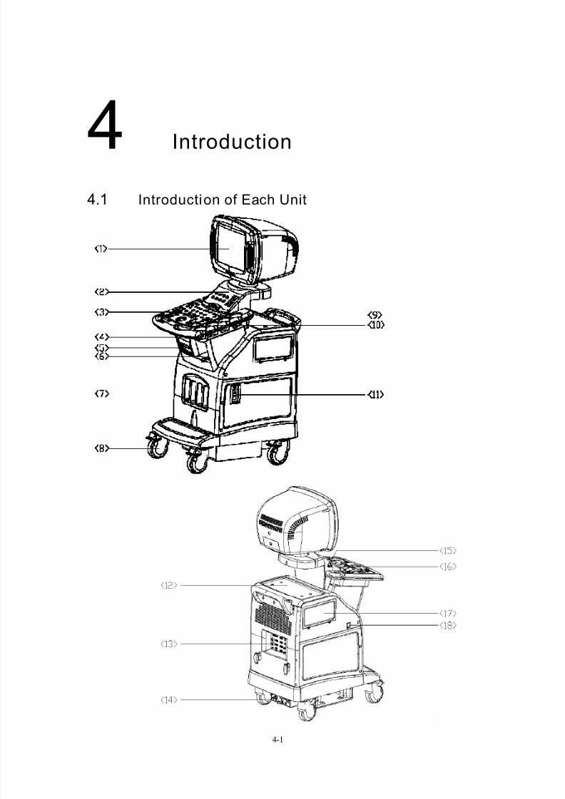
4.1 Introduction of Each Unit

7/16/2019 DC-6 Operation Manual Basic CE V1.1
http://slidepdf.com/reader/full/dc-6-operation-manual-basic-ce-v11 27/149
Introduction
4-2
No Name Function
<1> Monitor Displays the images and parameters during scanning
<2> Minor panel Human-machine interface, operation control
<3> Main panel Human-machine interface, operation control
<4> Keyboard Human-machine interface, operation control
<5> CD-RW Rewritable CD drive
<6> Space for placing
video printer
Used for placing B/W video printer
<7> Transducer socket Interface connecting transducers and the main unit
There are 3 active sockets and one dummy socket.
<8> Casters Used for fixing or moving the system
<9> Handle Used for pushing the system
<10> Transducer holder Used for placing transducers temporarily
<11> ECG panel Used for connecting the ECG cable and footswitch, etc.
<12> Table for placing
color printer
Used for placing color video printer
<13> I/O panel Interface panel for input and output signals
<14> Power panel Electrical interface panel
<15> USB interface Used for USB devices (The upper is used for USB
devices, while the lower is for expansion.)<16> MIC interface Reserved
<17> Space for placing Used for placing video recorder
<18> Power switch Used for turning on/off the power supply

7/16/2019 DC-6 Operation Manual Basic CE V1.1
http://slidepdf.com/reader/full/dc-6-operation-manual-basic-ce-v11 28/149
Introduction
4-3
4.2 I/O Panel
No Symbol Function
<1> Connects parallel port devices
<2>,<3> Ethernet interface
<4> System reset
<5> Serial port
<6> Control port for color video printer
<7>,<8> USB port (The lower is used for USB devices,
while the upper is for expansion.)
<9>,<10> Used for VGA I/O
<11>,<12> Used for RGB component video I/O
<13>,<14> Used for separate video I/O
<15>,<16> Used for compound video I/O
<17>,<18>
<19>,<20>
Used for stereo audio I/O
<1> <9> <13> <17>
<2> <5> <10> <14> <18>
<3> <6> <11> <15> <19>
<4><7> <12> <16> <20>
<8>

7/16/2019 DC-6 Operation Manual Basic CE V1.1
http://slidepdf.com/reader/full/dc-6-operation-manual-basic-ce-v11 29/149
Introduction
4-4
4.3 Power Panel
No Name Function
<1> Ground terminal Used for grounding connection
<2> Equipotential terminal Used for equipotential connection
<3> Power outlet Power supply for optional peripheral devices
<4> Circuit breaker Used for cutting off power supply of the system
<5> Power inlet AC power inlet
<1> <3>
<4>
<5>
<2>

7/16/2019 DC-6 Operation Manual Basic CE V1.1
http://slidepdf.com/reader/full/dc-6-operation-manual-basic-ce-v11 30/149
Introduction
4-5
4.4 ECG Panel
No Name Function
<1> ECG lead signal input
interface
Used for connecting ECG leads and acquiring
ECG signals
<2> External ECG signal
input port
Used for connecting the signal output port of
ECG monitor
<3> Footswitch interface Used for connecting the footswitch

7/16/2019 DC-6 Operation Manual Basic CE V1.1
http://slidepdf.com/reader/full/dc-6-operation-manual-basic-ce-v11 31/149
Introduction
4-6
4.5 Control Panel
4.5.1 Main panel
No English Name Function
<1> Patient Starting an exam of a new patient
<2> Info Entering the patient information input screen
<3> / Power indicator
<4> / Hard disk indicator
<5> SV Adjusting the size of sample volume
<6> Filter Adjusting wall filter frequency in the PW mode<7> PW Steer Adjusting SV steering angle of a linear transducer in the
PW mode
<8> Angle Adjusting SV corrected angle in the PW mode
<9> Scale Adjusting pulse repetition frequency in the
Color/Power/PW mode
<10> Baseline Adjusting baseline position in the PW/Color mode
<11> Doppler Freq Adjusting transmitting frequency in the Color/Power/PW
mode
<12> Color IP Selecting IP parameter combination in the Color/Power
mode<13> Color Filter Selecting wall filter in the Color/Power mode

7/16/2019 DC-6 Operation Manual Basic CE V1.1
http://slidepdf.com/reader/full/dc-6-operation-manual-basic-ce-v11 32/149
Introduction
4-7
<14> Color Steer Adjusting ROI steering angle of a linear transducer in the
Color/Power mode
<15> Focus Adjusting focus position for B images
<16> IP Selecting IP for B images
<17> Freq/THI Adjusting the current transducer frequency and harmonic
frequency
<18> B Steer Adjusting steering scan of a linear transducer
<19> CW Reserved
<20> PW Press the key to enter the PW mode, and rotate the key
to adjust gain of a PW image
<21> B Entering the B mode by pressing it, and adjusting the
gain by turning it
<22> Color Entering the Color Doppler mode by pressing it, and
adjusting the gain by turning it
<23> M Pressing the key to enter the M mode, and rotate the key
to adjust gain of an M image<24> Update Switching mode image in M/B mode or PW/B mode.
<25> Dual Entering Dual-split screen display, or switch live image
window in Dual.
<26> Quad Entering Quad-split screen display, or switch live image
window in Quad.
<27> Power Entering the Power Doppler mode by pressing it, and
adjusting the gain by turning it
<28> Save Cine Quickly saving cine files to the default region of the
internal hard disk in the preset image format
<29> Review Reviewing the image files of the current patient or the lastpatient.
<30> Save Img Quickly saving image files to the default region of the
internal hard disk in the preset image format.
<31> Cine In the frozen status, entering/exiting the manual Cine
playback status.
<32> iTouch Optimizing images by pressing this key
<33> Depth/Zoom When the Depth indicator lights on, the knob is used for
adjusting image depth by turning it; when the knob is
pressed down and the Zoom indicator lights on, the knob
is used for adjusting magnification factor by turning it.
<34> Freeze Freezing or unfreezing an image
<35> Menu Invoking or closing the menu corresponding to the
current status
<36> The multifunction knob is used with the current status
and trackball, and it has many functions. Please refer to
the operation description for details.
<37> Back Returning to the previous operation
<38> Change Changing the active point of the caliper during
measurement; or opening the comment library in the
comment status
<39> Set Confirming, equivalent to the left-button of the mouse

7/16/2019 DC-6 Operation Manual Basic CE V1.1
http://slidepdf.com/reader/full/dc-6-operation-manual-basic-ce-v11 33/149
Introduction
4-8
<40> Caliper Starting general measurement function
<41> Print Printing the screen image (video print control)
<42> trackball Adjusting the cursor’s position on the screen
<43> Arrow Adding comment arrows, and the arrow orientation is
adjusted through the multifunction knob.
<44> Comment Pressing the key to start the comment function, and the
system enters the comment status.
<45> Report Entering the current patient report
<46> Body Mark Starting the body mark function by pressing it and the
system enters the body mark edit status.
<47> Exit Exiting the current status and returning to the previous
status.
<48> Clear Clearing all comments, measurement calipers,
Clearing the selected body mark on image.
<49> Measure Starting application measurement functions.

7/16/2019 DC-6 Operation Manual Basic CE V1.1
http://slidepdf.com/reader/full/dc-6-operation-manual-basic-ce-v11 34/149
Introduction
4-9
4.5.2 Minor panel
No English Name Function
<1> / Reserved for future use, can be defined
<2> / Reserved for future use, can be defined
<3> / Reserved for future use, can be defined
<4> / Reserved for future use, can be defined
<5> Record Used for data recording
<6> ECG Entering or exiting the ECG menu
<7> iStation Entering the patient files management
<8> Probe Switching between effective transducers connected
and its exam mode.
<9> TGC Adjusting time gain compensation
<10> A.Power Adjusting Acoustic Output
<11> ECG Adjusting ECG signal position and ECG gain
<12> Volume Adjusting Doppler sound volume

7/16/2019 DC-6 Operation Manual Basic CE V1.1
http://slidepdf.com/reader/full/dc-6-operation-manual-basic-ce-v11 35/149
Introduction
4-10
4.5.3 Keyboard
Ejection of the keyboard
Push the edge of the keyboard inward slightly, and then the keyboard
automatically ejects outward. At this time the light under the main control panel is
bright automatically to lighten the keyboard.
Retraction of the keyboard
Push the keyboard inward, and when a click sound is heard, the keyboard is
retracted.

7/16/2019 DC-6 Operation Manual Basic CE V1.1
http://slidepdf.com/reader/full/dc-6-operation-manual-basic-ce-v11 36/149
Introduction
4-11
Functions of the keys
No Key Function
<1> Enter Receiving the input data; or moving the cursor to the head of
next row of the text or the input field.
<2> Esc Same as that of the『Exit』key
<3> Tab Jumping to the next operation
<4> Space Inserting a space
<5> Caps Lock Switching between upper and lower case letters
<6> Num Lock Switching between numerics and other characters
<7> Shift
Press the『Shift』key and another key simultaneously, and then
upper and lower case letters or upper and lower characters can
be switched; Shift+ +Set;
<8> Ctrl Combined shortcut, Ctrl+ +Set;
<9> Alt Combined key
<10> Pause/Break /
<11> HomeMoving the cursor to the head of the row, or the leftmost side of
an edit unit.
<12> EndMoving the cursor to the tail of the row, or the rightmost side of
an edit unit.
<13> PgUp Turning pages upward or leftward
<14> PgDn Turning pages downward or rightward
<15> Arrow Moving the cursor position
<16> Ins Switching between inserting and overwriting characters
<17> Del Deleting characters after the cursor
<18> Back Space Deleting characters before the cusor
<19> PrtSc /
<20> Win Logo /
<21> Application /
NOTE: ”/” symbols represent the keys are undefined.

7/16/2019 DC-6 Operation Manual Basic CE V1.1
http://slidepdf.com/reader/full/dc-6-operation-manual-basic-ce-v11 37/149
Introduction
4-12
Functions of the keys F1 to F12
No Key Function
<1> F1 /
<2> F2 Quickly starting the patient information screen (identical tothe 『Info』 key)
<3> F3 Quickly starting the diagnosis report screen (identical to the
『Report』 key)
<4> F4 Quickly starting the comment status (identical to the
『Comment』 key)
<5> F5 /
<6> F6 /
<7> F7 /
<8> F8 /
<9> F9 Switching to the video replay menu
<10> F10 Quickly starting preset function
<11> F11 Turning on/off the display of biopsy guide line
<12> F12 /
NOTE: for the keys undefined, the user can define functions for them as per needs and
habit. Refer to “Preset “chapter for details.

7/16/2019 DC-6 Operation Manual Basic CE V1.1
http://slidepdf.com/reader/full/dc-6-operation-manual-basic-ce-v11 38/149
Introduction
4-13
4.6 Symbols
This system uses the symbols listed in the following table, and their meanings
are explained as well. Refer to “Safety Precautions” for safety symbols.
Symbol Meaning
Type-BF device
! Refer to relevant content in the Operation Manual, to avoid
safety accidents
Dangerous voltage
AC (alternate current)
Functional earth
Equipotentiality
Protective earth
Breaker ON/OFF
Power ON/OFF
Footswitch
Transducer socket
Network port
Parallel port
Serial port
S-VIDEO signal interface
VIDEO signal interface
VGA signal
RGB signal
External signal input
Remote control port
USB

7/16/2019 DC-6 Operation Manual Basic CE V1.1
http://slidepdf.com/reader/full/dc-6-operation-manual-basic-ce-v11 39/149
Introduction
4-14
System reset
Audio signal
Microphone input jack
Product serial number
Manufacture date
Manufacturer
Authorized representative in the European community
The device is fully in conformance with the Council DirectiveConcerning Medical Devices 93/42/EEC. The number
adjacent to the CE marking (0123) is the number of theEU-notified body that certified meeting the requirements of Annex II of the Directive.

7/16/2019 DC-6 Operation Manual Basic CE V1.1
http://slidepdf.com/reader/full/dc-6-operation-manual-basic-ce-v11 40/149
5-1
5Placement and Connection
5.1 Placing the System
Please read and understand the safety precautions before placing the system.
(1) Unlock the four casters.
(2) Move the system by holding the handle.
(3) When the system is placed in a desired position, lock the four casters.
(4) Leave at least 20cm at the back and both sides of the system.
CAUTION: Ensure enough space at the back and both sides of the system;
otherwise failure may result due to the temperature rise in the system.
5.2 Connecting the Power Cable and Protective Earth
5.2.1 Connecting the power cable
The power system of the device must meet the following requirements:
100 to 127V~ or 220 to 240V~
50/60Hz
Power consumption: greater than 800VA.
The method of connection is described as follows:
(1) Push the retaining clamp upward, and put the power cable into the receptacle,
as shown in the figure below.
Retaining clamp
Power cableRecepticle

7/16/2019 DC-6 Operation Manual Basic CE V1.1
http://slidepdf.com/reader/full/dc-6-operation-manual-basic-ce-v11 41/149
Placement and Connection
5-2
(2) Push the retaining clamp downward, and lock the power cable, as shown in the
figure below.
5.2.2 Protective earth terminal
The power cable of the system is a three-wire cable. The grounding terminal should be
connected with the protective earth cable. Be sure that the power earth protection can work
normally.
WARNING:
1. Do not connect the three-wire cable of the system with a two-wire
plug; otherwise it may result in electric shock.
2. Be sure to connect this system and its peripheral devices to wall
receptacles, which shall meet the rated power requirement writ ten on
the plate. Adapters or multifunctional receptacles may cause the
leakage current to exceed the safety requirement.
In addition, please connect the video printer to the special auxiliary
power outlet of this system, and use the cable provided with this
system to connect the printer. Other cables may result in electricshock.

7/16/2019 DC-6 Operation Manual Basic CE V1.1
http://slidepdf.com/reader/full/dc-6-operation-manual-basic-ce-v11 42/149
Placement and Connection
5-3
5.2.3 Equipotential terminal
The symbol of represents the equipotential terminal that is used for balancing the
protective earth potentials between the system and other electrical equipment. Refer to“Power Supply Panel” for the relevant explanation.
WARNING:
1. Be sure to connect the equipotential lead wire before inserting the
power plug into the receptacle; also, be sure to remove the power
plug f rom the receptacle before disconnecting the equipotential
lead wire; otherwise, it may cause electric shock.
2. When you want to connect another device to this system, you
should use the equipotential cable to connect each of equipotential
terminals; otherwise electric shock may occur.
3. Information concerning the functional earth terminal ( ):
The user should connect the system according to the local
regulations.
4. Connect the earth cable only before turning ON the system.
Disconnect the earth cable only after turning OFF the system.
Otherwise, electric shock may occur.
5. Do not connect this system to the outlets with the same circuit
breakers and fuses that cont rol the current to devices such as
life-support systems. Once this system fails or generates an
overcurrent, or once there is an instantaneous current at power on,
the circuit breakers and fuses of the building’s supply circuit may
be tripped.
7/16/2019 DC-6 Operation Manual Basic CE V1.1
http://slidepdf.com/reader/full/dc-6-operation-manual-basic-ce-v11 43/149
Placement and Connection
5-4
5.3 Connecting/Disconnecting a Transducer
CAUTION:
1. Turn off the power of the system or freeze the image (through the
『Freeze』 key) before connecting/disconnecting of the transducer.
Otherwise, failure may occur.
2. When connecting o r disconnecting a transducer is, place it in the
transducer holder and hang the cable on the hook, to prevent the
transducer from falling of f and damaging.
3. When using a transducer, hang the cable on the hook , to prevent the
cable from twisting and damaging.
4. Only use the transducers provided by Mindray. Otherwise it may
result in damage or cause a fire.
5.3.1 Connecting a transducer
WARNING: Ensure the transducer, cable and connector to be in the normal
status (free from crack and peeling) before connecting the transducer. If
a defective transducer is used, electric shock may occur.
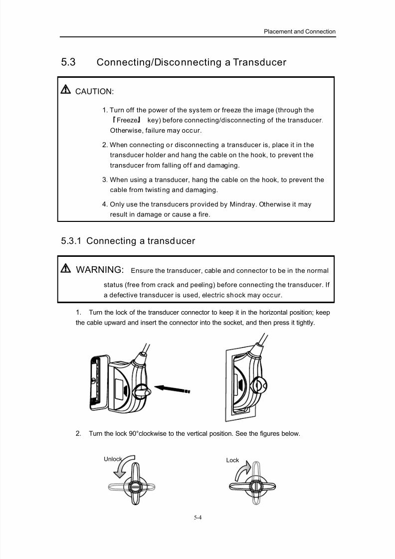
1. Turn the lock of the transducer connector to keep it in the horizontal position; keep
the cable upward and insert the connector into the socket, and then press it tightly.
2. Turn the lock 90°clockwise to the vertical position. See the figures below.
LockUnlock

7/16/2019 DC-6 Operation Manual Basic CE V1.1
http://slidepdf.com/reader/full/dc-6-operation-manual-basic-ce-v11 44/149
Placement and Connection
5-5
5.3.2 Disconnecting a transducer
Turn the locking lever 90°counterclockwise to the horizontal position, and pull out
the transducer connector along vertical direction, as shown in the figure below.
5.4 Connecting/Removing a USB Memory Device
1. When a USB memory device is connected to the ultrasound system through a
USB port, the symbol “ ” appears in the lower right corner of the screen.
2. To remove the USB memory device, move the cursor onto “ ”, and press
the『Set』key. A dialog box pops up.
3. Select the memory device to be removed, and press the [OK] button to remove
it.
WARNING: Do not remove a USB memory device directly; otherwise it
may damage the USB memory device and the ul trasound system.

7/16/2019 DC-6 Operation Manual Basic CE V1.1
http://slidepdf.com/reader/full/dc-6-operation-manual-basic-ce-v11 45/149
Placement and Connection
5-6
5.5 Connecting a Footswitch
The footswitch can control “Freeze” operation and “Print” operation remotely.
Connect the footswitch connector to the port at the bottom of the ECG panel, as
shown in the figure below, and then rotate the connector to fix it in position.
5.6 Connecting a graph/text printer
As shown in the figure below, a graph/text printer has a power cable and data cable,
and the power cable shall be directly connected to a wall receptacle as required. The
printer model shall be a specified model supported by this system. Refer to“Recommended Peripheral Devices” for specific models.
The procedures are described as follows:
(1) Connect the data cable to USB port of the system.
(2) Connect the power cable to a wall receptacle.
(3) Turn on the power of the ultrasound system.
(4) The installation process is complete.
Footswitch port
Footswitch
Data cable
Power cable

7/16/2019 DC-6 Operation Manual Basic CE V1.1
http://slidepdf.com/reader/full/dc-6-operation-manual-basic-ce-v11 46/149
6-1
6Power ON/OFF
6.1 Power ON
CAUTOIN: To ensure the safe and effective operation of the system, you
need to perform daily maintenance and checks. If you find any
abnormity, shut down the machine immediately and contact the
Mindray sales of fice, customer service department or representative. If you use the abnormal equipment, it may harm
patients and damage the equipment.
6.1.1 Checking before power ON
Before the system is turned on, please check the system as the following items:
No Check Item
<1> The temperature, relative humidity and atmospheric pressure shall meet therequirements of operating conditions.
<2> There shall be no condensation.
<3> There shall be no distortion, damage or dirt on the system and peripheral devices.
If any dirt is found, cleaning shall be performed as per “Cleaning the system”.
<4> There shall be no unsecured casters, monitor and main panel or loose screws.
<5> The locks of the casters shall work normally.
<6> There shall be no damage concerning the cables (including the power cable), and
connection of connectors shall be secured.
<7> The transducers and transducer cables shall be free of damage or stains.
If any stain is found, it shall be cleaned, disinfected and sterilized in terms of theoperation manual of the transducers.
<8> No sundries are allowed on the main panel.
<9> Check the outlet of the auxiliary power supply of this equipment and all I/O ports,
ensuring there is no abnormity such as damage or occlusion by foreign objects.
There shall no obstacles around the equipment and its air vent.
<10> Regarding cleaning, disinfection and sterilization of the transducers, refer to the
operation manual of the transducers.
<11> The field and environment shall be clean.

7/16/2019 DC-6 Operation Manual Basic CE V1.1
http://slidepdf.com/reader/full/dc-6-operation-manual-basic-ce-v11 47/149
Power ON/OFF
6-2
6.1.2 Turning on the power
First check whether the circuit breaker is switched on. If not, switch on the breaker.
After the power indicator on the main panel is on, turn on the power (on the left side of
the machine) to start the system. After the normal startup, the screen of the image is
displayed.
Check if the equipment is started normally according to the following items:
No Check Item
<1> There shall no abnormal sound, smell or overheating.
<2> There shall no error message displayed.
<3> There shall no evident noise, discontinuous display or black area on a B-modeimage.
<4> Check if there is abnormal heat on the surface of the transducer during operation.
<5> The keys and knobs on the panels and keyboard can function normally.
<6> The date and time of the system are identical to those of the current exam, andare correctly displayed.
WARNING:
1. If a transducer giving abnormal heat is used, it may burn the patient.
2. If any abnormity is detected, it indicates that the equipment isdefective. In this case, shut down the machine immediately and
contact your service representative.
NOTE: When you start the system or switch between transducers, you will hear a sound
of sputtering, which is regarded as normal.

7/16/2019 DC-6 Operation Manual Basic CE V1.1
http://slidepdf.com/reader/full/dc-6-operation-manual-basic-ce-v11 48/149
Power ON/OFF
6-3
6.2 Restart the System
When any of the following abnormalities occurs, the user can disconnect the power
cable of the system from the wall receptacle, and then restart the system after several
minutes:
• An error message is displayed and does not disappear.
• The screen display is abnormal.
• The system operations cannot be executed.
6.3 Power OFF
If the system will not be used for a long time, the power shall be turned off. Perform the
following operations: (1) Place the transducer on the transducer holder and hook the transducer cable.
(2) Turn off the power switch of the system on the left side. If the system will not be
used for a long period of time, please cut off the circuit breaker on the power panel
(namely, pull down the switch of the breaker). Do not directly switch off the breaker
without turning off the power switch first, since it may cause system failure.
(3) Turn off all the power supplies of the peripheral devices connected to this
equipment.

7/16/2019 DC-6 Operation Manual Basic CE V1.1
http://slidepdf.com/reader/full/dc-6-operation-manual-basic-ce-v11 49/149
7-1
7Basic Screen and Operation
7.1 Basic Screen
The monitor is to display the ultrasound images, parameters and operation menus. The
menus and parameters vary depending upon image scanning modes.
The basic screen is generally divided into: information field, image field, active window
field, menu and image parameter field, measurement result field, status prompt field, andshortcut tool field.
Measurement
result field
Menu & image
parameter field
Information field
Image field
Active window field
Status prompt field Shortcut tools field
7/16/2019 DC-6 Operation Manual Basic CE V1.1
http://slidepdf.com/reader/full/dc-6-operation-manual-basic-ce-v11 50/149
Basic Screen and Operation
7-2
7.1.1 Information field
The information field displays manufacturer logo, hospital name, patient information,
system date and time, transducer model and current frequency, current exam mode,
and freezing mark etc.
Manufacturer logo
The Mindray’s logo “ ” is displayed in the upper left corner of the screen.
Hospital name
The hospital name is displayed on the screen, and it can be set through the “General”
item in the system preset dialog box.
Patient information
The patient name, ID, Gender and Age are displayed on the screen, and they can beentered through the patient information input dialog box or loaded old patient.
System date and t ime
The system date and time are displayed on the screen, and the date, time and format
can be set through the “General” item in the system preset dialog box.
Transducer model
The model of the currently used transducer is displayed on the screen. The transducer
model can be selected in the transducer selection dialog box.
Current exam modeThe currently used exam mode, such as adult abdomen etc. is displayed.
7.1.2 Image field
The image field displays ultrasound image, comment, measurement caliper, body mark,
scale mark, grey bar and color bar.
Ultrasound image
The display width and shape of an image depend upon the selected transducers and
setups. And it already displays depth scale indication, focus mark, and selected grey
bar or color bar.
Comments and body marks
The comments are used to assist analysis and explanation of images, and they consist
of comment texts and comment arrows. The body marks indicate the probing position
on patient body and probing orientation of a transducer, when an image is scanned.
Measurement caliper
In the general measurement status and measurement statuses of various applications,
the measurement calipers are displayed in the image field during measurement.
However, after some operations are performed (e.g., unfreezing operation),measurement calipers will be cleared.
7/16/2019 DC-6 Operation Manual Basic CE V1.1
http://slidepdf.com/reader/full/dc-6-operation-manual-basic-ce-v11 51/149
Basic Screen and Operation
7-3
7.1.3 Menu and image parameter field
Menus
The menus are grouped into image control menus, measurement menus and control
program menus. The menus are generally in the status of suspension, and the user canpress the『Menu』key to open the suspended menus. After a menu is suspended, the
position of the menu will display the current image parameter information.
Image control menu
Most of the image control menu items belong to parameter-adjusting menu items.
Pressing the『Set』key or 『Back』key can switch between parameter values or options.
Measurement menu
The measurement menus are different depending upon image modes and applications
measurement packages. Most of measurement menu items belong to
command-executing menu items. Pressing the『Set』key on a menu item can start ameasurement. The menu items with a submenu work in the same way. Move the cursor
onto a menu item, its submenu automatically opens, and pressing a submenu item can
start a measurement.
Control program menu
The control program menu is used to start a new program or menu of screen operation,
such as preset menu and file menu. The control program menu generally belong to
command-type menu, and pressing the『Set』key can start a new screen. For the [OK]
and [Cancel] buttons on the screen, pressing the [OK] button can confirm the
information changes on the screen and exit the screen; pressing the [Cancel] button
can cancel the information changes to return to the previous information on the screen
and remain in the current status and exit the screen.
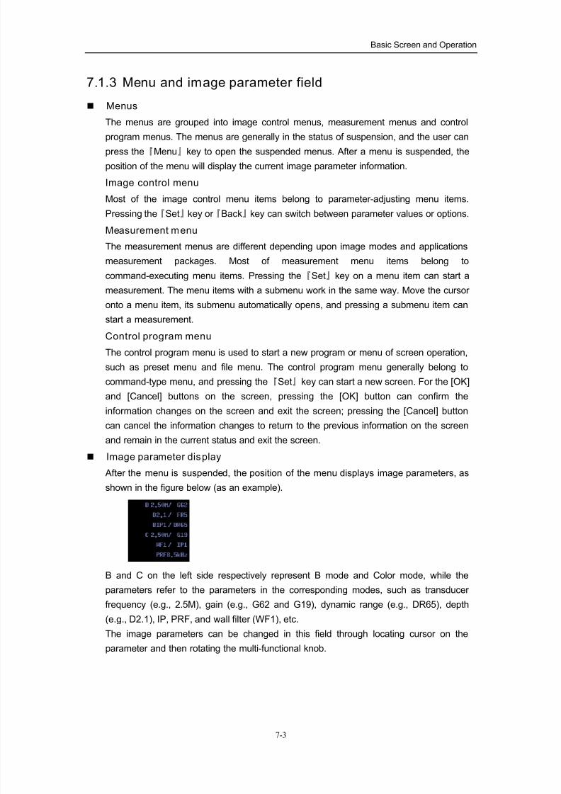
Image parameter display
After the menu is suspended, the position of the menu displays image parameters, as
shown in the figure below (as an example).
B and C on the left side respectively represent B mode and Color mode, while the
parameters refer to the parameters in the corresponding modes, such as transducer
frequency (e.g., 2.5M), gain (e.g., G62 and G19), dynamic range (e.g., DR65), depth
(e.g., D2.1), IP, PRF, and wall filter (WF1), etc.
The image parameters can be changed in this field through locating cursor on the
parameter and then rotating the multi-functional knob.

7/16/2019 DC-6 Operation Manual Basic CE V1.1
http://slidepdf.com/reader/full/dc-6-operation-manual-basic-ce-v11 52/149
Basic Screen and Operation
7-4
7.1.4 Measurement result field
The measurement result field displays the results of measurements and calculations.
The measurement result is generally displayed in real time. Before the measurement
caliper is fixed, moving the cursor can refresh the result in real time. After themeasurement caliper is fixed, the result will be constantly displayed.
7.1.5 Act ive window field
The active window field displays body mark selection window, image review window,
and ECG waveform display (only valid for the system with ECG module). It also displays
acoustic output parameters.
Acoust ic output parameters
The acoustic output parameters include MI/TI real time parameters and acoustic power
level (such as AP1). Refer to “Acoustic Output” section for MI/TI.
Acoustic power level represents ultrasound transmitting power, and it can be adjusted
through the『 A.power 』key on the main panel.
7.1.6 Status prompt field
The left side of the field displays help information in the current status (such as free
cursor status, Cine review status, SV or ROI adjusting status etc,), as shown in the
figure below:
The right side of the field shows USB device connecting information, recorder status,
and network status etc..
7.1.7 Shortcut tool field
The shortcut tool field, right below the image, displays shortcut tools as per the current
status (an example is taken as follows):
Move the cursor onto a shortcut tool button, and the name of the tool will appear. Press
『Set』 or 『Back』 key to adjust values.
Free cursor status
SV adjusting status
Cine review status
Zoom status

7/16/2019 DC-6 Operation Manual Basic CE V1.1
http://slidepdf.com/reader/full/dc-6-operation-manual-basic-ce-v11 53/149
Basic Screen and Operation
7-5
7.2 Basic Operations of Dialog
The schematic of a dialog box is shown in the figure below. A dialog box generally
consists of several parts as shown in the figure.
Composition Description
Title Bar The title bar is used to give a general description for the content
and function of the dialog box.
Page tab
For some dialog box, contents are designed to distribute on
several pages. To set parameters, it needs to select pages and
switch between pages. Pressing the『Set』key on the page tab
can switch to the corresponding page.
Adjustable items Pressing the『Set』 or 『Back』key can adjust the values.
「OK」and「Cancel」
When the operation of a dialog box is complete, the user can
press the「OK」or 「Cancel」button to save or cancel the
operation, and close the dialog box.
z Drag a dialog box
To drag a dialog box, the method is described as follows:
1. Roll the trackball to move the cursor onto the title bar of the dialog box, and at this time
the cursor becomes “ ”; press the『Set』key.
2. Roll the trackball, and there is a rectangular frame, the same size as that of the dialog
box, moves with the cursor; position the rectangular frame to the place where the dialog
box will be moved.
3. Press the『Set』key, and the dialog box moves to the desired position.
4. After step 2, pressing the『Back』key can cancel the operation of dragging the dialog box
and the dialog box remains in the original position.

7/16/2019 DC-6 Operation Manual Basic CE V1.1
http://slidepdf.com/reader/full/dc-6-operation-manual-basic-ce-v11 54/149
8-1
8Patient Information
Although the user can start scanning a patient without entering patient information, it is
recommended to enter patient information before an image is scanned. Thus the
system can create the patient database, to avoid the data confusion.
CAUTION: Before examining a new patient, press the『Patient』key to update
patient ID and information; Otherwise, the new data may be confused with
the data of the previous patient.
8.1 Entering/Exiting Patient Information
To enter the patient info screen:
When examining a new patient, press the『Info.』key or 『F2』key. Or move the cursor
onto the patient info display field, and press the『
Set』
key to enter the “Patient Info”dialog box.
To exit the patient info screen:
In the “Patient Info” dialog box, clicking the [Ok] button can save the patient information
and exit the dialog box; clicking the [Cancel] button or pressing the『Exit』 key or
pressing 『Info』key again will not save the current information, but exit the dialog box.

7/16/2019 DC-6 Operation Manual Basic CE V1.1
http://slidepdf.com/reader/full/dc-6-operation-manual-basic-ce-v11 55/149
Patient Information
8-2
8.2 Patient Information Input
8.2.1 Basic patient information
In the new patient exam, pressing the 『Info.』can enter the patient info screen, as
shown in the figure below:
The operation of patient information input is described as follows:
ID
If the user selects the “Auto ID” item following the patient ID column, and the system will
automatically create patient ID.
If the user deselects the “Auto ID” item following the patient ID column, and the system
will default it as manual input of patient ID. If the user enters a patient ID that has
existed in the database, when the user clicks [OK], the system will pop up the message
for loading the ID data.
User can preset auto ID or input ID manually in system preset.
Name, Gender and Age
Name:
The user can directly enter patient name through the alphanumeric keyboard, and
characters of “A through Z, 0 through 9” and “.” are allowed; the user can also switch to
Chinese input method to enter Chinese characters. Refer to the Appendix for the
Chinese input method.
Gender:
The user can click to select Male or Female.
DOB:
The user can enter the birth date of a patient, and the system will automatically
calculate the patient age and display it on the screen. The age unit is either “Years”,
“Months” or “Days”. If the age is less than one year, the system will automatically

7/16/2019 DC-6 Operation Manual Basic CE V1.1
http://slidepdf.com/reader/full/dc-6-operation-manual-basic-ce-v11 56/149
Patient Information
8-3
calculate age in months or days. The user can either enter the birth date manually, or
click the “ ” icon following the entry box, and then the system will display the date
control as shown in the figure below:
Comment
The user can enter the comment information if necessary.
Move the cursor to select the corresponding item in the patient list of the “iStation”
window, and continuously pressing the『Set』key twice or clicking the『Info.』button on
the screen can view the patient information.
Select a patient, click the [Begin Exam], then load the patient information as the current
patient information.
8.2.2 Detailed patient information
Click on the “Patient Info” screen to open the detailed patient information
screen. The detailed information consists of “General” and “OB”.
The general information contains: Height, Weight, BSA (automatically calculated by the
system) and Formula, BP, HR, physician information, patient phone number and
address.

7/16/2019 DC-6 Operation Manual Basic CE V1.1
http://slidepdf.com/reader/full/dc-6-operation-manual-basic-ce-v11 57/149
Patient Information
8-4
The OB information contains:
(1) LMP : Last Menstrual Period
(2) EDD by LMP : Estimated Date of Delivery, calculated by LMP
(3) GA by LMP : Gestational Age, calculated by LMP
(4) Exp. Ovular : Expected date of Ovulation
(5) EDD by Exp. Ovular : Estimated Date of Delivery, calculated by Exp. Ovular
(6) GA by Exp. Ovular : Gestational Age, calculated by Exp. Ovular
(7) Gestation : number of embryo
(8) Gravida : times of pregnancy
(9) Para : times of delivery
(10) Ectopic : times of ectopic gestation
(11) Aborta : times of abortion
(12) Days of cycle : days of Menstrual cycle

7/16/2019 DC-6 Operation Manual Basic CE V1.1
http://slidepdf.com/reader/full/dc-6-operation-manual-basic-ce-v11 58/149
Patient Information
8-5
8.3 Importing Patient Information Worklist
After installing the DICOM software package and setting the worklist server, the user
can click “ ” to import the patient information, as shown in the figure below:
The operation is described as follows:
1. Determine the data source: select the worklist server.
2. Set conditions of the patient to whom the worklist is imported: ID, patient name,
DOB or exam date.
3. Click “ ”, and then the system will search the corresponding patient
information according to the set conditions.
4. To change the conditions, click “ ” to reset the conditions.
5. In the patient worklist, select the desired patient to be imported, and click [OK] to
import the patient information to the ultrasound system.

7/16/2019 DC-6 Operation Manual Basic CE V1.1
http://slidepdf.com/reader/full/dc-6-operation-manual-basic-ce-v11 59/149
9-1
9Exam Modes
CAUTION: Once the exam mode is changed during a measurent, all
measurement calipers on the image will be cleared. The data of
general measurements may be lost, but the data of application
measurements are stored in the reports.
9.1 Instruction of Exam Modes
This system can configure the following exam modes:
1. Adult ABD (Adult abdominal)
2. Adult Cardiac
3. GYN (Gynecology)
4. OB1 (First trimester)
5. OB2/3 (Second and third trimester)
6. Fetal Cardiac
7. Kidney
8. Prostate
9. THY (Thyroid)
10. Breast
11. Other SMP (Other small parts)
12. Carotid
13. Per Vein (Peripheral vein)
14. Per Artery (Peripheral artery)
15. Ped ABD (Pediatric abdominal)
16. Ped Cardiac (Pediatric cardiac)
17. User 1
18. User 2
19. User 3
20. User 4

7/16/2019 DC-6 Operation Manual Basic CE V1.1
http://slidepdf.com/reader/full/dc-6-operation-manual-basic-ce-v11 60/149
Exam Modes
9-2
9.2 Selecting Exam Modes
Connect a transducer to the system, and press the『Probe』key to open a dialog box as
shown in the figure below. Roll the trackball to move the cursor to select exam modes
corresponding to the transducer and press the『Set』key to confirm.
9.3 Presetting Exam Modes
In the preset menu, select the [Exam Preset] item, and click it to enter the exam preset
screen.
Click the [Preset] button on of the transducer screen, and the user can also enter the
exam preset screen.
The exam preset screen consists of exam selection for transducers and parameter
setup for exam modes, i.e., “Exam Selection” and “Exam Config”.

7/16/2019 DC-6 Operation Manual Basic CE V1.1
http://slidepdf.com/reader/full/dc-6-operation-manual-basic-ce-v11 61/149
Exam Modes
9-3
9.3.1 Exam Selection
After the exam preset screen is entered, the dialog box generally displays the ”Exam
Selection” page, as shown in the figure below. This page is used to set applied exam
modes for the specified transducer.
The operating method is described as follows:
1. Select a transducer: move the cursor onto the column “ ”,
and select the transducer model through the drop-down menu.
2. On the right side of the screen, the user can view the exam modes supported by
the current transducer; on the left side, the user can view all the exam modes
supported by the system, i.e., “Exam Library”. To delete a mode supported by the
current transducer, select the mode first, and then click to delete it. To add
a mode for the current transducer, select the mode from the exam mode library on
the left side, and click to add it to the “Exam Selected” column. Click
to add all different items between the exam library and exam selected to
the “Exam Selected” column.
3. After the selected exam modes are set, the user can arrange the order of these
exam modes. By means of the “ ” and “ ” buttons, the user can
adjust the order of these exam modes one by one.
4. To set some exam modes to default exam modes for the transducer, first select
the exam modes, and then click .
5. Clicking “ ” can confirm the modified setup; clicking “ ” can cancel the
modified setup.
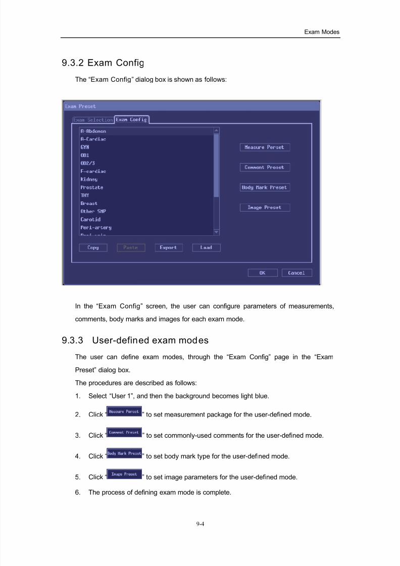
7/16/2019 DC-6 Operation Manual Basic CE V1.1
http://slidepdf.com/reader/full/dc-6-operation-manual-basic-ce-v11 62/149
Exam Modes
9-4
9.3.2 Exam Config
The “Exam Config” dialog box is shown as follows:
In the “Exam Config” screen, the user can configure parameters of measurements,
comments, body marks and images for each exam mode.
9.3.3 User-defined exam modes
The user can define exam modes, through the “Exam Config” page in the “Exam
Preset” dialog box.
The procedures are described as follows:
1. Select “User 1”, and then the background becomes light blue.
2. Click “ ” to set measurement package for the user-defined mode.
3. Click “ ” to set commonly-used comments for the user-defined mode.
4. Click “ ” to set body mark type for the user-defined mode.
5. Click “ ” to set image parameters for the user-defined mode.
6. The process of defining exam mode is complete.

7/16/2019 DC-6 Operation Manual Basic CE V1.1
http://slidepdf.com/reader/full/dc-6-operation-manual-basic-ce-v11 63/149
10-1
10 Image Modes
WARNING:
The images displayed in this system are only reference for diagnosis.
Mindray is not responsible for correctness of diagnostic results , while thephysician, who performs the exam, is responsible for the correctness of
diagnostic results.
10.1 Categories of Image Modes
The system supports the following image modes:
B mode;
M mode;
Color mode;
Power/DirPower mode;
PW mode

7/16/2019 DC-6 Operation Manual Basic CE V1.1
http://slidepdf.com/reader/full/dc-6-operation-manual-basic-ce-v11 64/149
Image Modes
10-2
10.2 Switching Between Image Modes
Key Selecting and Switching
B mode knob; pressing it can enter B mode; turning it can adjust B gain
M mode knob, press the key to enter the M mode, and rotate the key to
adjust gain of M image.
PW mode knob, press the key to enter the PW mode, and rotate the key to
adjust gain of PW image
Reserved.
Color mode knob; pressing it can enter Color mode; turning it can adjust
gain.
Power mode knob; pressing it can enter Power mode; turning it can adjust
gain.
Dual-split display key, Press the key to enter the Dual-split display mode.
Quad-split display key, Press the key to enter the Quad display mode.
Switching key; press it can cyclically switch image windows in the PW +B
or M+B mode.

7/16/2019 DC-6 Operation Manual Basic CE V1.1
http://slidepdf.com/reader/full/dc-6-operation-manual-basic-ce-v11 65/149
Image Modes
10-3
10.3 Image Adjustment
The image adjustment is performed through the image menus and control panels. The
user can switch options on the menus through the『Set』key and『Back』 key, or keep
the cursor on the menu item, and rotate the multi-functional knob to adjust parameters
or options. The panel-adjusting items are adjusted through the buttons or sliders on the
panels.
10.3.1 B mode
Change B image display
In the B mode, the user can change display depth, reverse (horizontally or vertically) an
image, rotate an image, change view field of an image, or magnify an image.
Change display depth
Through the『Depth/zoom』button on the main panel, the user can adjust the display
depth when the “Depth” indicator lights on.
The adjustable depth values vary depending upon transducer types.
Reverse/rotate an image
Left/Right reverse: through the [L/R Reverse] item in the B image menu can switch
between Left and Right. Or clicking the image” ” icon at the
bottom of an image can reverse the image horizontally.
Up/Down reverse: through the [U/D Reverse] item in the B image menu can switch
between Up and Down. Or clicking the image” ” icon at the
bottom of an image can reverse the image vertically.
Rotation: through the [Rotation] item in the B image menu can cyclically select
between rotation angles.
The user can identify image orientation through the “M” mark on the screen: by default,
the M mark is located in the upper left corner.
Change view field of an image
Scan Range:
The scan range can be changed by adjusting scan angle. The scan range setup has
four selections and they can be switched through the “Scan Range” item in the image
menu.
Steering scan:

7/16/2019 DC-6 Operation Manual Basic CE V1.1
http://slidepdf.com/reader/full/dc-6-operation-manual-basic-ce-v11 66/149
Image Modes
10-4
The steering scan function is only valid for linear transducers, and the steering angle is
adjusted through the『B Steer 』lever on the main panel.
Optimizing B image
The change of image-optimizing parameters affects the image quality, and the user can
adjust them as per actual needs.
iTouch
The iTouch key is used to optimize image parameters as per the current tissue
characteristics, in order to obtain better image effect. The function is realized through
the『iTouch』key on the main panel.
Gain
To adjust the B image gain, turn the『B』knob on the main panel.
TGC
TGC (time gain compensation) control is used to adjust depth gain to optimize an image
in different segments of the image. The system has 8-segment TGC sliders, and the
user can adjust them as per needs. Move sliders to the right, gain increases,
corresponding area image brightness increases; move sliders to the left, gain decreases,
corresponding area image brightness decreases.
Focus number
To change focus number in the scan field, the user can switch between options of
“Focus Number” in the image menu.
Focus position
To change the focus position, the user can adjust the『Focus』lever on the main panel.
Line density
It is used to change scan density. The higher the scan line density, the smaller the
frame rate. The user can switch it through the “Line Density” item in the image menu.
MBPMBP (that is Multi-beam Parallel Imaging) increases temporal resolution and real-time
frame rate, while collecting useful information to re-build high quality images. The user
can adjust it “ON” or “OFF” in the image menu.
Dynamic range
The dynamic range function is used to adjust contrast resolution of the image to
compress or expand grey display range. The user can adjust numeric through the
“Dynamic Range” in the image menu or image parameters field.

7/16/2019 DC-6 Operation Manual Basic CE V1.1
http://slidepdf.com/reader/full/dc-6-operation-manual-basic-ce-v11 67/149
Image Modes
10-5
Colorize
User can open or close the colorize function through the “colorize” item in the image
menu.
In “Colorize Map”, user can select Colorize code. The position where the grey scale bar
is displayed displays Colorize code.
The user can also click the “ ” icon below the image to oen or close colorize function.
TSI (tissue specific imaging)
This function is used to select acoustic speed according to tissue characteristic, and this
system can set four specific tissues, i.e., general, muscle, fluid and fat. The user can
switch between selections.
Frame average
This function is used to superimpose and average adjacent B images, to remove image
noise, making image details to be clearer. The user can perform this function through
the “Frame Average” item in the image menu.
Smooth
This function is to reject image noise, making images to be smooth. The user can adjust
it through the “Smooth” item in the image menu. The smaller the value, the lower the
smooth; whereas the bigger the value, the higher the smooth.
Noise rejection
This function is to reject image noise, thus increasing signal-noise ratio. The user can
adjust it through the “Noise Reject” in the image menu. The smaller the value the lower
rejection; whereas the bigger the value the higher the rejection.
AGC
AGC refers to automatic gain control, used to increase acoustic shadow in bright area
and dark area. The user can adjust automatic gain level through the “AGC” menu item.
The smaller the value the smaller the AGC; whereas the bigger the value the bigger the
AGC.
Edge enhancement
This function is used to increase image profile, in order to distinguish image boundary.
The user can adjust it through “Edge Enhance” in the image menu. This function can be
set to “OFF” if it is not used.
IP
IP refers to a combination of image processing parameters, including dynamic range,
edge enhancement, smooth, frame average, AGC and noise rejection. This system can
preset 8 groups of IP combinations, and the user can switch between groups of

7/16/2019 DC-6 Operation Manual Basic CE V1.1
http://slidepdf.com/reader/full/dc-6-operation-manual-basic-ce-v11 68/149
Image Modes
10-6
combinations through the『IP』lever, and the IP combination number is displayed on the
upper right side of the screen. The user can view it when the menu hides.
THI (tissue harmonic imaging)
The system provides the THI function, and the user can adjust the『Freq/THI』lever to
switch to THI. In the THI condition, adjusting『IP』 can generate the “THI IP” value, and
the user can also preset “THI IP” in the image parameter preset.
Gray map
The system presets several gray maps, and each map is derived from combination of
grey transform curve, grey rejection curve and γ correction. The user can select “Map1”
to “Map8” through the “Gray Map” item in the image menu, and can preset “Map” in the
image parameter preset.
Post process
Post processing is used to apply the gray correction to the image in order to obtain the
image with optimum map.
The user can use the post processing submenu of the image menu to adjust the grey
transform curve, grey rejection curve and γ correction.
The post processing is valid for real time, frozen and Cine reviewed images.
Gray Transform:
1. Click [Curve], and the gray transform curve pops up;
2. Move the cursor onto a node “·”of the curve, and the cursor becomes ““ ”; press
the『Set』key, and roll the trackball to move the “·” to adjust the grey transform
cursor, and the user can see that the image changes with the adjustment;
3. Press the『Set』key again, fix the “·” node in the new position, and the cursor
resumes to “ ”. Repeat the above process, the user can adjust the next node;
pressing the『Back』key can cancel the adjustment, and the “·” resumes the
previous position.
4. Press the『Set』key on the 「Linear Transform」item, and the grey transform
becomes a 45°straight line;
5. Clicking the「OK」key can confirm the adjustment and exit the status; clicking the「Cancel」can resume the previous curve and exit the status.
The adjustment is shown in the following figures:

7/16/2019 DC-6 Operation Manual Basic CE V1.1
http://slidepdf.com/reader/full/dc-6-operation-manual-basic-ce-v11 69/149
Image Modes
10-7
Gray Rejection:
The gray rejection is to reject image signals less than certain grey scale.
1. Click the [Rejection] item of the [Post Process] menu in the B image menu or M
image menu, the “gray rejection” dialog box pops up;
2. Move the cursor onto “▲”, and the cursor becomes “ ”, and press the『Set』key;roll the trackball to move the “▲” to adjust the gray rejection curve. The user can
see that the image changes with the adjustment;
3. After adjustment, press the『Set』key again, and the cursor resumes to ” ”; or
pressing the『Back』can cancel adjustment, the “▲” resumes the previous position.
4. Pressing the『Set』key on「OK」can confirm the curve adjustment and exit the status,
and the “gray rejection” dialog box disappears; or selecting「Cancel」can resume
the previous curve and exit the status, and the “gray rejection” dialog box
disappears.
The adjustment is shown in the following figures:
γ correction:
γ correction is used to correct the non-linear distortion of images.
γ correction parameters are represented by 0, 1, 2, and 3, respectively representing
coefficients of 1, 1.1, 1.2, and 1.3.
The user can adjust [γ] item of the [Post Process] submenu in the B image menu or M
image menu, and the γ correction parameters are displayed on this menu item.
7/16/2019 DC-6 Operation Manual Basic CE V1.1
http://slidepdf.com/reader/full/dc-6-operation-manual-basic-ce-v11 70/149
Image Modes
10-8
10.3.2 M mode
Change M image
Scan speed
This function is used to set the refreshing speed of M images. The user can adjust it
through the “Speed” item in the M image menu. The smaller the value, the faster
refreshing speed; whereas the bigger the value, the slower the refreshing speed.
Time mark
This function is used to turn on or off the display of the time mark on the M image. The
user can set the “Time Mark” through the M image menu.
Full screen
The full screen function refers to the M image be displayed in full screen, and it is set
through the “Full Screen” item of the M image menu. Turning on this function can only
display the M image, while turning it off displays the M+B images.
Optimizing adjustment
The meaning and adjustment of most parameters of M images are similar to those of B
images, so adjustment of Colorize, dynamic range, edge enhance, AGC, gray maps, IP,
post processing will not be repeated here. Refer to relevant sections of B images. The
following is to introduce the special parameters of M images.
Gain
Rotating the『M』knob on the main panel can adjust the M image gain.
Line Correlation
This function is used to process the scan lines of M images to reject noise, making the
image details to be clearer. The user can adjust it through the “Line Correlation” item in
the image menu. The smaller the value, the smaller the line correlation.
Smooth
This function is to obtain smooth transition of M images. The user can adjust it through
the “Smooth” in the M image menu. The smaller the value, the smaller the smooth.
Image enhancement
Image enhancement is used to increase acuteness of M images, and it is adjusted
through the “Image Enhance” item in the M image menu.

7/16/2019 DC-6 Operation Manual Basic CE V1.1
http://slidepdf.com/reader/full/dc-6-operation-manual-basic-ce-v11 71/149
Image Modes
10-9
10.3.3 Color mode
The color flow mode is used to detect color flow information, and the color is designed
to judge the direction and speed of blood flow. Generally the color above the color bar
indicates the flow towards the transducer, while the color below the color bar indicates
the flow away from the transducer; the brighter the color, the faster the flow speed;
whereas the darker the color, the slower the flow speed.
Change image display format
Baseline
Adjusting baseline to change the range of blood speed, the user can adjust the color
bar baseline through the 『Baseline』key on the main panel.
Color reverse
Clicking [Reverse] in the image menu can switch between “ON” or “OFF”. When “ON” is
set, the color bar is reversed.
ROI Color
Clicking the [ROI Color] item in the image menu can change the ROI color. There are up
to 8 colors for selection.
B/C Wide
The maximum width is set to be the same as that of a B image. This function can be
switched through “ON” and “OFF” in the menu.
B/C Sync
This function is used to synchronously display B image and Color image, and the
window will be automatically switched to the dual windows (one for B image, the other
for Color image) when the function is turned on. It is selected through the Color image
menu.
Image Disp
This function is used to turn on or off the B image display outside the color ROI, and it is
set through the Color image menu.
Optimizing adjustment
Color gain
This function is used to adjust color gain, and can be adjusted through the『Color 』key
on the main panel.
Color frequency
This function is adjusted through the『Doppler Freq』lever on the main panel.
Wall f ilter
This function is used to adjust the cut-off frequency of wall filter, and can be adjusted

7/16/2019 DC-6 Operation Manual Basic CE V1.1
http://slidepdf.com/reader/full/dc-6-operation-manual-basic-ce-v11 72/149
Image Modes
10-10
through the 『Color Filter 』lever on the main panel.
PRF
The PRF value is used to adjust the speed range of the color flow, and can be adjusted
through the『Scale』lever on the main panel.
Steering angle
This function is used to adjust the scan angle of linear transducers, and can be adjusted
through the『Color Steer 』lever on the main panel.
Color map
The color map is a group of the color image map parameters, and can be switched
through the image menu. The user can also click the “ ” icon below the image to
switch between color maps.
Line density
This function is used to change scan density. The user can switch it through the “Line
Density” item in the image menu.
MBP
MBP (that is Multi-beam Parallel Imaging) increases temporal resolution and real-time
frame rate. The user can turn on or off the function through the “MBP” item in the image
menu.
Packet size
The packet size is used to adjust the accuracy of blood flow. The parameter can be
switched through the image menu.
Smooth
This function is to reject image noise, making images to be smooth. The user can adjust
it through the “Smooth” item in the image menu. The smaller the value, the lower the
smooth; whereas the bigger the value, the higher the smooth.
Persistence
The persistence is a parameter for temporal smooth. The user can adjust its levels
through the image menu.
Contrast
The contrast refers to contrast of color maps. The user can adjust it through the image
menu. The bigger the value the stronger the contrast; whereas the smaller the value the
weaker the contrast.
Priority
This function is used to set levels of the flow display, and it is adjusted through the
image menu.

7/16/2019 DC-6 Operation Manual Basic CE V1.1
http://slidepdf.com/reader/full/dc-6-operation-manual-basic-ce-v11 73/149
Image Modes
10-11
Focus position
This function is used to adjust the color focus position relative to the B focus. The user
can adjust it through the [Focus Position] item in the image menu. When its value is
changed, the transmit focusing delay changes accordingly.
10.3.4 Power/DirPower mode
Power mode is used to image blood flow by displaying the density of red blood cells, as
opposed to their velocity, in the form of different brightness, but it doesn’t provide the
directional information. However, the DirPower (Directional Power Doppler) mode can
provide information of the flow velocity and direction.
Most parameter adjustments of Power mode are consistent with those of the Color
mode and the dynamic range adjustment is consistent with that of B mode. Refer to
relevant section of the Color mode and B mode. The parameters are adjusted through
the control panel or the Power image menu. The following is to introduce the special
items of the Power mode.
Map (Power Map / DirPower Map)
The maps in the Power image menu are grouped into two categories: Power maps and
Directional Power maps. The former four belong to Power maps, and the latter four
belong to Directional Power maps. The Power maps provide information of flow speed;
the Directional Power maps provide not only information of flow speed but also
information of flow direction.
The operator can switch among the maps through the "Map" item in the Power image
menu to select the desired one.
LVR(Low velocity rejection)
The low velocity rejection function is to shield the information of some low velocity flow.
The user can adjust the rejection levels through the [Low Vel. Reject] item in the Power
image menu. The bigger the value the bigger the flow speed rejected; the user can turn
off this function.
7/16/2019 DC-6 Operation Manual Basic CE V1.1
http://slidepdf.com/reader/full/dc-6-operation-manual-basic-ce-v11 74/149
Image Modes
10-12
10.3.5 PW mode
PW mode (Pulsed Wave Doppler mode) scan produces a series of pulses used to study
the motion of blood flow at a small region along a desired scan line. The X-axis of the
graph represents time while the Y-axis represents Doppler frequency shift. The shift can
be converted into velocity and flow if an appropriate angle between the beam and blood
flow is known. The thickness of the spectral signal is indicative of laminar or turbulent
flow.
Scan speed
The user can click the [Speed] item in the image menu to switch between different scan
speed levels.
Colorize
Adjustment of PW Colorize is identical to that of B mode Colorize.
Reverse
Clicking the [Reverse] item in the menu can switch between “ON” and ”OFF” options.
When the option is set to “ON”, the frequency spectrum is reversed.
Size and angle of sample volume
Moving the『SV』lever on the main panel can adjust the width of the sample volume.
Moving the『PW Steer 』lever on the main panel can adjust the steering angle of SV.
Rotating the『 Angle』knob on the main panel can adjust the correction angle of SV.
Baseline
Moving the『Baseline』key on the main panel can adjust the baseline.
Wall fi lter
The PW mode wall filter is to adjust the cut-off frequency of wall filter, and the user can
adjust it through the『Filter 』lever on the main panel.
PRF
The PRF value is to adjust the flow speed range, and the user can adjust it through the
『Scale』lever on the main panel.
Color frequency
This function is adjusted through the『Doppler Freq』lever on the main panel.
Simul
When the [Simul] item in the PW image is set to “ON”, it indicates that the image in the
B/Power mode is simultaneously scanned, i.g., the system enters the PW+B (or Power)
double real time mode. When it is set to “OFF”, it indicates that it is non double real time

7/16/2019 DC-6 Operation Manual Basic CE V1.1
http://slidepdf.com/reader/full/dc-6-operation-manual-basic-ce-v11 75/149
Image Modes
10-13
mode.
Auto Trace
PW Auto Trace function is to set the maximum speed, average speed and maximum
scattering value of tracing through the PW image menu.
Set type of trace through [Auto Trace] submenu;
The level change of [Threshold] is only valid for the maximum speed trace, used to
change the trace coefficient.
When [Trace Area] is set to “ALL”, the whole spectrum will be traced; when it is set to
“Top”, the spectrum above the baseline will be traced; when it is set to “Bottom”, the
spectrum below the baseline will be traced.
The [Trace Smooth] item is to set the smooth of tracing.
Audio
The user can set the PW audio to “ON” or “OFF” through the PW menu.
Time mark
When a spectrum is viewed, the time mark facilitates to specify the time information of
special points. The user can set the [Time Mark] item to “ON” or ”OFF” through the PW
menu.
Full Screen
The full screen function refers to the PW image be displayed in full screen. Turning on
this function can only display the PW image, while turning it off displays the PW+B
images.
10.3.6 Acoustic power
The acoustic power refers to the power of the ultrasound transmitted by the transducer.
The acoustic power shall be selected according to practical situations and ALARA
principle.
Rotating the『 A.Power 』knob can adjust the acoustic power. The acoustic power level is
displayed right below the image (as well as MI/TI).
10.3.7 Image magnification
Press the “ ” key, the “Zoom” indicator lights on, and the system enters the
magnification status. Rotating the knob can adjust the magnification factor.
In the Zoom status, rolling the trackball can move the amplified image so as to view the
detail.
Pressing it again or pressing the『Exit』key can exit the magnification status.

7/16/2019 DC-6 Operation Manual Basic CE V1.1
http://slidepdf.com/reader/full/dc-6-operation-manual-basic-ce-v11 76/149
Image Modes
10-14
10.4 Image Parameter Preset
The user can enter the image parameter preset screen through the “Image Preset” item
in the [Preset] menu or “ ” on the “Exam Preset” page.
The image preset is used to set image parameters for a specific transducer in a specific
exam mode. The setting methods are similar although parameter items are different in
each image mode. The following is to take B/THI image mode for the 3C5 transducer in
adult abdominal exam mode as an example.
The “Use 1 - All Probe” field on left side of the screen displays the general parameter
setup for all transducers in abdominal exam mode. The “Use 1 - 3C5” field on the right
side of the screen displays parameter setup for the 3C5 transducer in User1 exam
mode.
The operation of the image parameter setup is easy, and the user can click options or
select in the drop-down menu. The following is to introduce the [Load Factory] function
and [Record Current] function.
[Load Factory]:
Click [Load Factory], and the parameter setup in all pages will resume the factory setup.
[Record Current]:
Clicking [Record Current] can quickly store the currently-used parameter values for
each parameter item in the image parameter preset, and the setup is valid for all pages
of this dialogue box.

7/16/2019 DC-6 Operation Manual Basic CE V1.1
http://slidepdf.com/reader/full/dc-6-operation-manual-basic-ce-v11 77/149
Image Modes
10-15
IP parameter preset:
Click the [BIP] or [THI IP] button, and the corresponding IP combination preset can be
entered, as shown in the figure below. The user can set the parameter values of each IP
combination, and click [OK] to store the new setup.
Preset of gray map:
Clicking [Gray Map] on the “Image Preset” screen can enter the preset of gray map, as
shown in the figure below.
Refer to relevant B mode chapter for adjustment of post processing curves.
The system can preset 8 post processing maps, which can be selected through the
image menu.
[Record Current]:
Clicking [Record Current] can quickly store the currently-used parameter values for
each parameter item in the image parameter preset, and the setup is valid for the
current preset page.

7/16/2019 DC-6 Operation Manual Basic CE V1.1
http://slidepdf.com/reader/full/dc-6-operation-manual-basic-ce-v11 78/149
11-1
11Cine Review
After freezing, the system allows user to review and edit the images prior to freezing.
This function is called as Cine review. The magnified images can also be reviewed after
freezing, and the operating method is same. The user can change post processing
effect, perform measurements, add comments and body marks on the images being
reviewed.
The Cine review function of the system supports to be reviewed manually and
automatically; the default setup is Manual Cine, but the user can switch between Auto
Cine and Manual Cine.
CAUTION: 1. Before a new patient is examined, press the『Patient』key to
clear the Cine memory, to avoid confus ion of new and old patient
images and misdiagnosis.
2. The Cine files stored in the hard disk contain patient information for
reference, to avoid error and misdiagnosis.
11.1 Entering/Exit ing Cine Review
Entering Cine Review:
Press the『Freeze』key to freeze an image, and the『Cine』key indicator lights on, and
then the system automatically enters the Manual Cine status.
Exiting Cine Riview:
Press the 『Freeze』 key again, the system will return to scanning image and exit cine
review.
Press『Cine』key or 『Exit』key, the images are already in freezing but the system exit
cine review.

7/16/2019 DC-6 Operation Manual Basic CE V1.1
http://slidepdf.com/reader/full/dc-6-operation-manual-basic-ce-v11 79/149
Cine Review
11-2
11.2 Cine Review in the B/Color Mode
When the cine review in B or Color mode, roll the trackball, the Cines wiil be displayed
in turn on the screen. Roll the trackball to the right, and the Cineloop sequences will be
displayed in ascending order of frame number; whereas roll the trackbll to the left, andthe Cineloop sequences will be displayed in descending order of frame number.
The Cine process bar at the bottom of the screen (as shown in the figure below): the
whole bar represents the total frame number, the numerics following the indicating bar
represent the current frame No and the total frame No. The slider represents the
currently reviewed frame number.
In the Manual Cine status, turning the multifunction knob can switch to Auto Cine. While
Cineloop sequences are being reviewed, turning the multifunction knob can change the
speed of Auto Cine.
In the Auto Cine status, rolling the trackball can end the Auto Cine and enter the Manual
Cine.
11.3 Cine Review in the PW/M Mode
When the cine review in PW or M mode, roll the trackball, the Cine will be displayed in
turn on the screen. Roll the trackball to the left, the review process slider moves to the
left, the images moves to right, and the earlier stored images are invoked; whereas
move the trackball to the right, the review process slider moves to the right, and images
move to the left, the recent stored images are invoked.
The cine review process bar is displayed at the bottom of the screen (as shown in the
figure below). The numerics following the indicating bar represent the current time and
the total time in the M/PW mode.
To switch between Auto Cine and Manual Cine, the method is identical to that of the
B/Color mode.
11.4 Linked Cine ReviewThe linked Cine review refers to simultaneous review of real-time images in the M+B,
PW+B (or Color) mode.
If the images in the two windows aren’t real time at the same time, the user can only
review images in the current active window.
Refer to description in sections 11.1 and 11.2 for cine review operations. However, in
the linked cine review, B/Color images shall be simultaneously displayed with M/PW
images.

7/16/2019 DC-6 Operation Manual Basic CE V1.1
http://slidepdf.com/reader/full/dc-6-operation-manual-basic-ce-v11 80/149
Cine Review
11-3
11.5 Setting Region of Auto Review
For the Cine images reviewed, the user can set a region to review that be interested.
After the auto review region is set, the auto Cine review can only be performed within
this region; but the manual Cine review can be performed beyond this region. When theCine file is saved, only the images within this region are saved.
After the system enters the Cine review status, perform the following procedures to set
the reviewed region. After the process of setting is complete, the new reviewed region is
between the two triangle marks (as shown in the figure below):
Method 1:
1. Return images to the first image frame to be reviewed, and press the『Set』 key to
set the triangle mark for the start position.
2. Press the 『Change』 key to switch to the end position.
3. Return images to the last image frame to be reviewed, and press the『Set』 key to
set the end position.
4. Rotate the multi-functional knob to enter the auto review.
Method 2:
1. Manually return images to the first image to be reviewed, and press the 『Menu』
key to open the freeze menu, and click [Set Start] to set the start position.
2. Press the『Menu』key to close the freeze menu, and the system returns to the Cine
review status.
3. Manually return images to the last image to be reviewed, and press the『Menu』to
open the freeze menu, and click the [Set End] to set the end position.
4. Click [Review Loop Range] to enter the Auto Review status.
11.5.1 Relative preset
The user can preset the default review time in the system preset screen. Enter the
preset screen, and open the [General] page. In the “File Store” field, the “Cine Store”item is located at the bottom, as shown in the figure below.
For Without ECG (s), the setting is second(s), referring to the duration from the moment
of freezing counted down to the set time point.
For With ECG (loop), the setting is cardiac cycles, which can only be selected through
the drop-down menu. The cardiac cycles can be selected in the range of 1 through 3.
Start End

7/16/2019 DC-6 Operation Manual Basic CE V1.1
http://slidepdf.com/reader/full/dc-6-operation-manual-basic-ce-v11 81/149
12-1
12Measurements
WARNING:
1. Be sure to measure correct objects in effective area during measurements;
otherwise it may cause misdiagnosis.
2. When a measurement of Doppler flow is performed, do not let the direction of a
transducer be perpendicular to the direction of the flow; otherwise information of the flow cannot be displayed and misdiagnosis may occur.
CAUTION:
1. During the measurements, once the freezing status is unfrozen or the
exam mode is changed, all the measure calipers will be cleared and the
general measurement data will be lost (application measurement data
are stored in reports).
2. During the measurements, When you turn of f the system or press the
『Patient』key, all the data not saved will be lost.
12.1 Basic Operation
12.1.1 Entering the measurement status
Pressing the or key can enter the measurement status. The image
menus on the right side of the screen are respectively corresponded to the general
measurement menu and application measurement menu. Press the same key again will
exit measurements status.
The measurement operation can be performed not only on a magnified image and Cine
reviewed image, but also on a real-time image and frozen image.
12.1.2 Measurement result and Help information
The system displays and updates measurement results in the result display area.
The Help information concerning measurement and calculation is displayed in the Help
bar at the bottom of the screen.
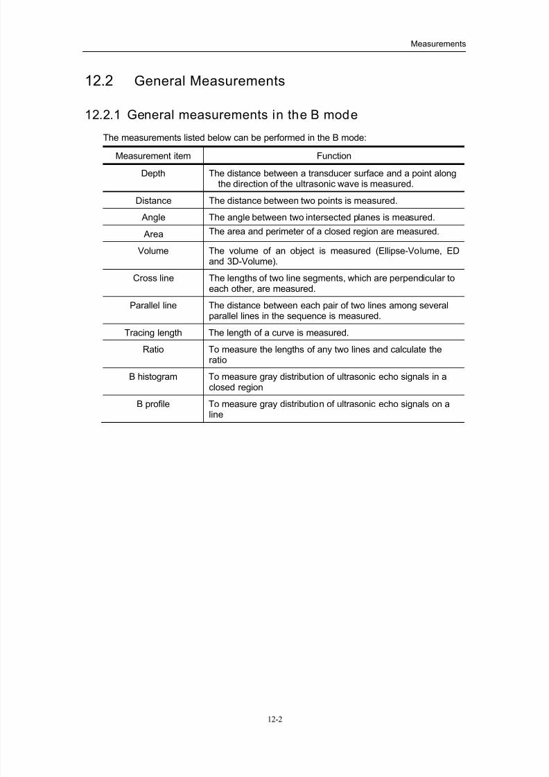
7/16/2019 DC-6 Operation Manual Basic CE V1.1
http://slidepdf.com/reader/full/dc-6-operation-manual-basic-ce-v11 82/149
Measurements
12-2
12.2 General Measurements
12.2.1 General measurements in the B mode
The measurements listed below can be performed in the B mode:
Measurement item Function
Depth The distance between a transducer surface and a point alongthe direction of the ultrasonic wave is measured.
Distance The distance between two points is measured.
Angle The angle between two intersected planes is measured.
Area The area and perimeter of a closed region are measured.
Volume The volume of an object is measured (Ellipse-Volume, EDand 3D-Volume).
Cross line The lengths of two line segments, which are perpendicular toeach other, are measured.
Parallel line The distance between each pair of two lines among severalparallel lines in the sequence is measured.
Tracing length The length of a curve is measured.
Ratio To measure the lengths of any two lines and calculate theratio
B histogram To measure gray distribution of ultrasonic echo signals in aclosed region
B profile To measure gray distribution of ultrasonic echo signals on aline

7/16/2019 DC-6 Operation Manual Basic CE V1.1
http://slidepdf.com/reader/full/dc-6-operation-manual-basic-ce-v11 83/149
Measurements
12-3
12.2.2 General measurements in the M mode
The measurements listed below can be performed in the M mode:
Measurement item Function
Distance The vertical distance between two points is measured.
Time The time interval between any two points is measured.
Slope The average speed (slope) is calculated by means of measuring the distance and time between two points.
Heart rate On an M HR image, the interval of n (n≤8) HR cycles ismeasured, and the number of HR per minute is calculated.
12.2.3 General measurements in the PW mode
The measurements listed below can be performed in the PW mode:
Measurement item Function
Time The time interval between any two points is measured.
Heart rate The interval of n (n≤8) HR cycles is measured, and the number of HR per minute is calculated.
Speed On the PW-mode image, speed and pressure difference of apoint on the Doppler spectrum waveform are measured.
Acceleration On the PW-mode image, speed and interval of two points aremeasured, and speed difference and acceleration are
calculated.Resistance index On blood flow waveform in the PW mode, the speeds of two
peak points are measured, and RI (Resistance Index) and theratio value are calculated.
Spectrum trace On the PW-mode image, the speed, difference and index of Doppler waveforms are obtained through tracing one or several Doppler waveforms. The range of auto trace isselected through [Spectrum Range].
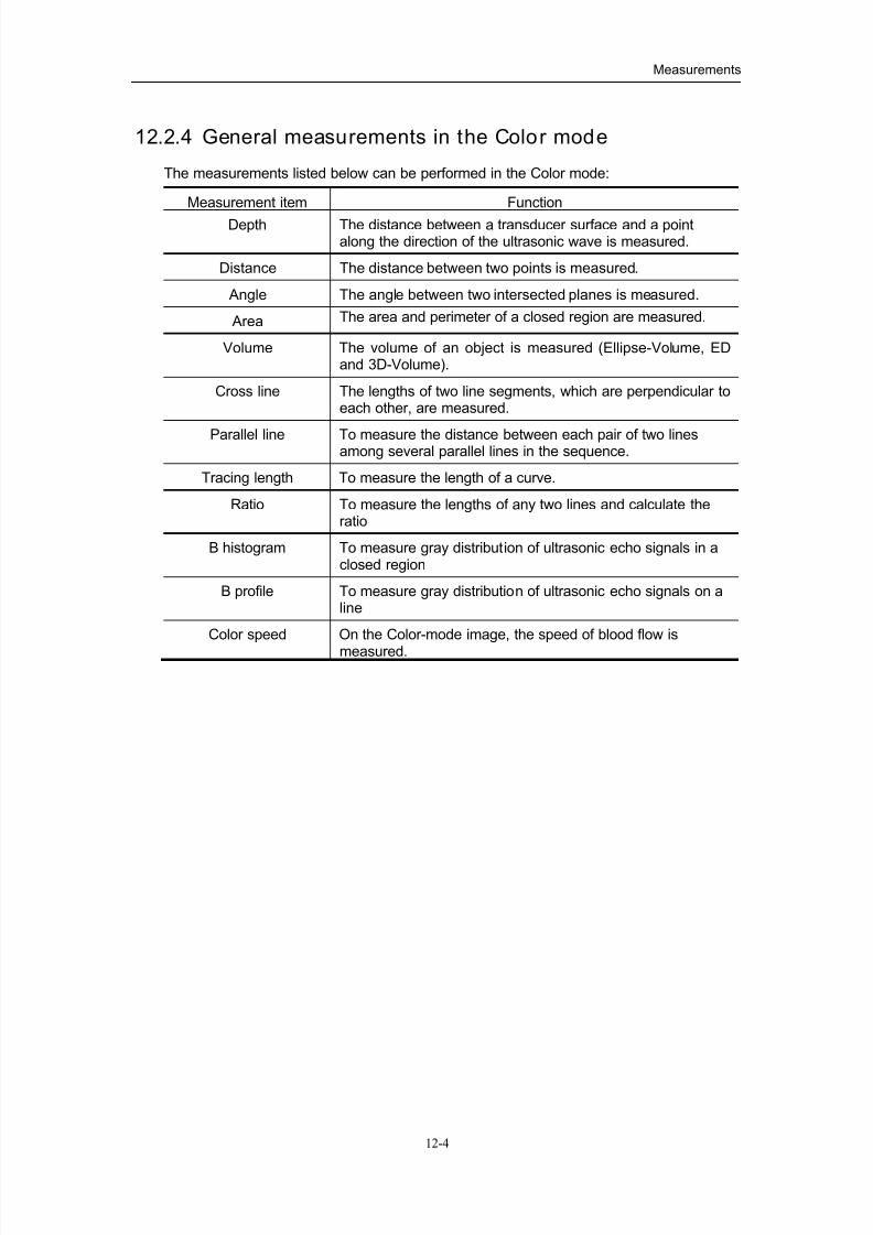
7/16/2019 DC-6 Operation Manual Basic CE V1.1
http://slidepdf.com/reader/full/dc-6-operation-manual-basic-ce-v11 84/149
Measurements
12-4
12.2.4 General measurements in the Color mode
The measurements listed below can be performed in the Color mode:
Measurement item Function
Depth The distance between a transducer surface and a pointalong the direction of the ultrasonic wave is measured.
Distance The distance between two points is measured.
Angle The angle between two intersected planes is measured.
Area The area and perimeter of a closed region are measured.
Volume The volume of an object is measured (Ellipse-Volume, EDand 3D-Volume).
Cross line The lengths of two line segments, which are perpendicular toeach other, are measured.
Parallel line To measure the distance between each pair of two linesamong several parallel lines in the sequence.
Tracing length To measure the length of a curve.
Ratio To measure the lengths of any two lines and calculate theratio
B histogram To measure gray distribution of ultrasonic echo signals in aclosed region
B profile To measure gray distribution of ultrasonic echo signals on aline
Color speed On the Color-mode image, the speed of blood flow is
measured.
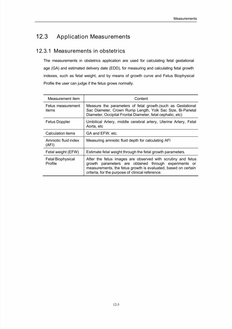
7/16/2019 DC-6 Operation Manual Basic CE V1.1
http://slidepdf.com/reader/full/dc-6-operation-manual-basic-ce-v11 85/149
Measurements
12-5
12.3 Application Measurements
12.3.1 Measurements in obstetrics
The measurements in obstetrics application are used for calculating fetal gestational
age (GA) and estimated delivery date (EDD), for measuring and calculating fetal growth
indexes, such as fetal weight, and by means of growth curve and Fetus Biophysical
Profile the user can judge if the fetus grows normally.
Measurement item Content
Fetus measurementitems
Measure the parameters of fetal growth.(such as GestationalSac Diameter, Crown Rump Length, Yolk Sac Size, Bi-Parietal
Diameter, Occipital Frontal Diameter, fetal cephalic, etc)
Fetus Doppler Umbilical Artery, middle cerebral artery, Uterine Artery, Fetal Aorta, etc
Calculation items GA and EFW, etc.
Amniotic fluid index(AFI)
Measuring amniotic fluid depth for calculating AFI
Fetal weight (EFW) Estimate fetal weight through the fetal growth parameters.
Fetal BiophysicalProfile
After the fetus images are observed with scrutiny and fetusgrowth parameters are obtained through experiments or measurements, the fetus growth is evaluated, based on certain
criteria, for the purpose of clinical reference.

7/16/2019 DC-6 Operation Manual Basic CE V1.1
http://slidepdf.com/reader/full/dc-6-operation-manual-basic-ce-v11 86/149
Measurements
12-6
12.3.2 Measurements in cardiology
The measurement items include left ventricle function measurement and measurements
of main artery and vein parameters. The measurement items are listed in the table
below:
Measurement item Content
Cardiacmeasurements
The measurement items include:
left ventricle function
RV
left ventricular mass weight
Right Ventricular End Diastolic Diameter
heart rate
ejection time
Blood flowmeasurements
The measurement items include:
aorta
blood flow of aorta
blood flow of pulmonary artery
blood flow of pulmonary vein
mitral valve
blood flow of mitral valve
blood flow of tricuspid valve
flow volume

7/16/2019 DC-6 Operation Manual Basic CE V1.1
http://slidepdf.com/reader/full/dc-6-operation-manual-basic-ce-v11 87/149
Measurements
12-7
12.3.3 Measurements in gynecology
The application measurement for gynecology is used for the uterus, ovary and dominant
follicle.
Measurement item Content
Uterus The measurement items include:
Uterus body
Cervix
Endometrial thickness
Ovary volume Left ovary volume and right ovary volume
Dominant folliclemeasurement
Left dominant follicle and right dominant follicle (up to 8)
12.3.4 Measurements in small parts
The application measurement for small parts is used for small parts such as thyroid.
Measurement item Content
Thyroid volume Left and right thyroid volumes
12.3.5 Measurements in urology
The application measurement for urology is used for prostate volume, seminal vesicle,
kidney volume, renal cortex thickness, adrenal gland, remnant volume, testicle volume.
Measurement item Content
Prostate Using rectum scanning method to measure prostate volume,and calculating prostate specific antigen based on theformula.
Seminal vesicle Measuring sizes of left and right seminal vesicles
Kidney Measuring volumes of left and right kidneys
Adrenal Gland Measure length, width and thickness of adrenal gland.
Remnant Measuring remnant urine volume after micturition, i.e. size of a bladder after micturition
Testicle Measuring the volume of a testicle

7/16/2019 DC-6 Operation Manual Basic CE V1.1
http://slidepdf.com/reader/full/dc-6-operation-manual-basic-ce-v11 88/149
Measurements
12-8
12.3.6 Measurements in orthopedics
The application measurement for orthopedics is mainly used for hip joint measurement.
Measurement item Content
HIP Draw BL (baseline), ARL, and IL and calculate hip joint angle;then estimate the type of dislocation based on age and angle force
of the infant..
12.3.7 Measurements in peripheral vessels
The application measurement for peripheral vessels is used for carotid vessel, upper
and lower limbs vessels. The PV measurement items are listed in the table below:
Measurement item Content
Carotid vessels The measurement items include:
Common carotid artery
Internal carotid artery
External carotid artery
Vertebral artery
Upper and lower limbs vessels
Upper and lower limbs vessels
Vessel parameters Flow speed Length stenotic ratio
Area stenotic ratio
Eastimated flow volume through vessel diameter
Eastimated flow volume through vessel area

7/16/2019 DC-6 Operation Manual Basic CE V1.1
http://slidepdf.com/reader/full/dc-6-operation-manual-basic-ce-v11 89/149
13-1
13Comments
Comments are often required to add on ultrasonic images during diagnosis, thus
enhancing readability of the images. The comments can be added on frozen images, as
well as reviewed images and magnified images. The types of comments include: texts
and indicating arrows.
WARNING: Ensure that the entered comments are correct. Incorrect
comments may cause misdiagnosis!
13.1 Entering/Exiting Comments
Press key to enter the comment status, and the cursor turns to “|”.
Pressing the『Comment』key again or any other operating mode key can exit the
comment status.
13.2 Comment Menu
In the comment status, pressing the『Menu』key can show or hide the comment menu.
Through the menu, the user can change the font size and arrow size of comments, or
enter the dialog box of comment preset. The menu is shown in the figure below:
In addition, clicking the” ” icon in shortcut tools bar can also change the font size
and arrow size of comments.

7/16/2019 DC-6 Operation Manual Basic CE V1.1
http://slidepdf.com/reader/full/dc-6-operation-manual-basic-ce-v11 90/149
Comments
13-2
13.3 Adding Comments
13.3.1 Typing characters
After the system enters comment status, the procedures of typing characters through
the keyboard are shown as follows:
1. Localize comments
Roll the trackball or press the 『→』,『←』,『↑』 or 『↓』key to move the cursor to
the desired position.
2. Type characters
Enter the comments directly through the keyboard;
To enter a character on the upper characters of a key, press the『
Shift』
key andthe corresponding key at the same time, and the entry method is the same as
that of the PC keyboard;
3. Line feed
In the edit status of comments (characters are green), press the『Enter 』key, the
cursor changes to the next line, and its position is lined up with the first line.
4. In the edit status of comments, move the trackball or press the『Set』keykey to
confirm the added characters, and the color of the characters turns to yellow.

7/16/2019 DC-6 Operation Manual Basic CE V1.1
http://slidepdf.com/reader/full/dc-6-operation-manual-basic-ce-v11 91/149
Comments
13-3
13.3.2 Comment library
1. In the comment status, place the cursor in the desired position in the image.
2. Turn the multifunction knob to display the general comment texts of the exam
mode one by one.
3. Press the『Change』key to display the comment library dialog box, as shown in the
figure below:
4. Search the desired comment text
Select the category first and click its tab to enter the page. Move the scroll bar on the
right side to search the desired comment text.
5. Select comment text
Move the cursor on the desired comment text and press the『Set』key, and the
system automatically adds the selected text to the specified position and closes the
dialog box. At this time the added comment text is in the edit status, so the user can
edit this comment text.
6. Press the『Set』key or move the trackball to confirm the comment text.
If there is no desired comment text in the comment library and it needs to exit the
library, place the cursor on the [Close] button of the dialog box and press the 『Set』
key to close the dialog box.
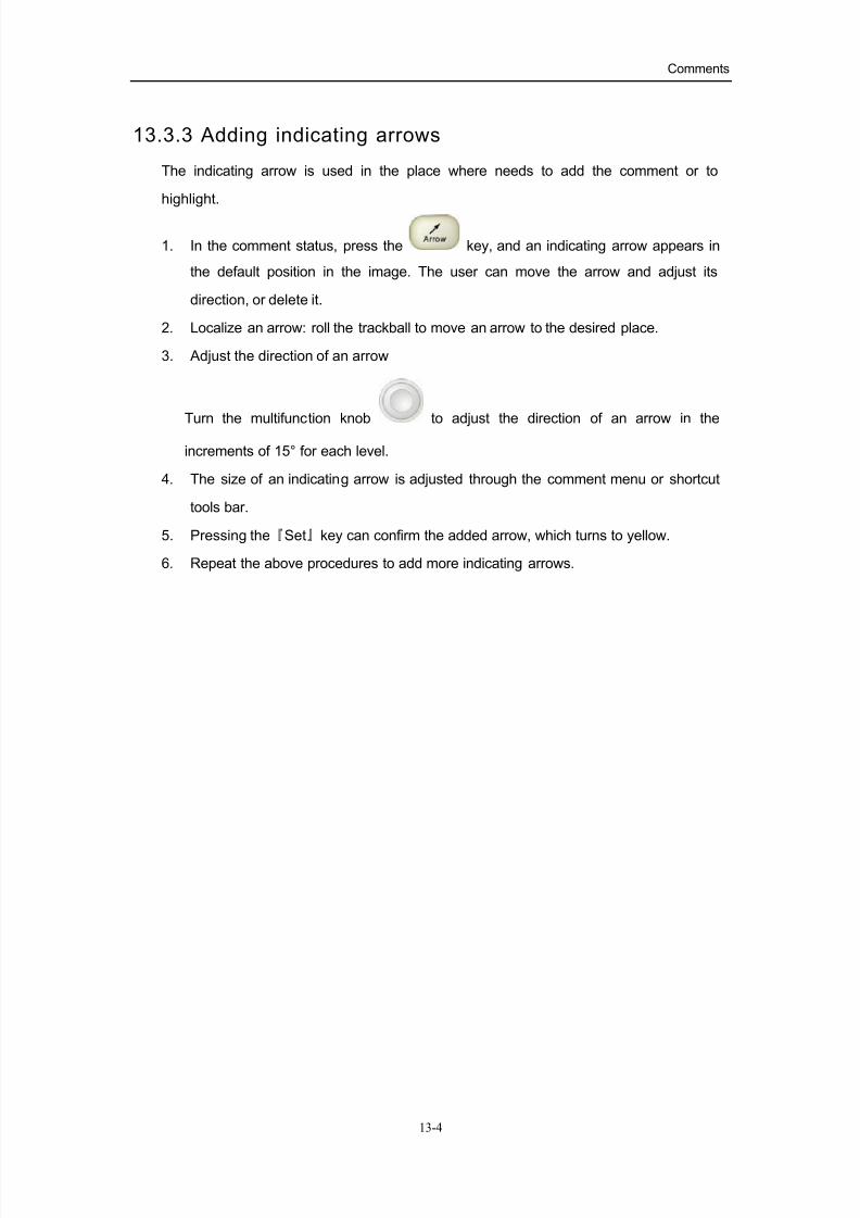
7/16/2019 DC-6 Operation Manual Basic CE V1.1
http://slidepdf.com/reader/full/dc-6-operation-manual-basic-ce-v11 92/149
Comments
13-4
13.3.3 Adding indicating arrows
The indicating arrow is used in the place where needs to add the comment or to
highlight.
1. In the comment status, press the key, and an indicating arrow appears in
the default position in the image. The user can move the arrow and adjust its
direction, or delete it.
2. Localize an arrow: roll the trackball to move an arrow to the desired place.
3. Adjust the direction of an arrow
Turn the multifunction knob to adjust the direction of an arrow in the
increments of 15° for each level.
4. The size of an indicating arrow is adjusted through the comment menu or shortcut
tools bar.
5. Pressing the『Set』key can confirm the added arrow, which turns to yellow.
6. Repeat the above procedures to add more indicating arrows.

7/16/2019 DC-6 Operation Manual Basic CE V1.1
http://slidepdf.com/reader/full/dc-6-operation-manual-basic-ce-v11 93/149
Comments
13-5
13.4 Moving Comments
1. In the comment status, roll the trackball to move the cursor onto the comment that
needs to be moved. Press the『Set』key to select it, and at this time a highlighted
frame appears around the comment.
2. Roll the trackball to move the comment to the new position.
3. Press the『Set』 key to anchor the comment in the new position, and the
comment-moving operation is complete.
13.5 Modifying Comments
13.5.1 Modify characters
1. Roll the trackball to move the cursor on the comment that needs to be modified,
and press the『Set』key to select it.
2. Press the『Set』key again to enter the edit status.
3. Use the『→』or 『←』key to move the cursor to a place where needs to insert
characters, and type characters or select the new comment text from the comment
library; pressing the『Del』key can delete the comment character or text on the right
side of the cursor, and pressing the『Backspace』key can delete the comment
character or text on the left side of the cursor.
4. Press the『Set』key to confirm the modification and to exit the edit status, and the
color of the comments turns to yellow.
13.5.2 Modify indicating arrows
1. Roll the trackball to move the cursor on the arrow that needs to be modified. The
cursor turns to “ ”, and press the『
set』
key. The color of the current arrow turns to
green, and there is green frame around the arrow, indicating the arrow can be
edited. Moving the cursor can modify the arrow position.
2. Turn the multifunction knob to modify the arrow direction.
3. Press the『set』key to complete the modifying operation.

7/16/2019 DC-6 Operation Manual Basic CE V1.1
http://slidepdf.com/reader/full/dc-6-operation-manual-basic-ce-v11 94/149
Comments
13-6
13.6 Deleting Comments
13.6.1 Delete characters
1. Roll the trackball to a position where needs to delete comment characters.
2. Press the『set』key to select the character to delete.
3. Press the『Del』key or 『Backspace』key to complete the deleting operation, and the
cursor turns to the comment cursor.
13.6.2 Delete arrows
1. Press the『Change』key to select the newly added arrow, enabling it to become
active arrow. Press the『Change』key to repeatedly select the newly added arrows
in reverse order, until the desired arrow is selected.
Or move the cursor until it turns to “ ”, and press the『set』key to select the
targeted arrow.
2. Press the『Del』key or 『Backspace』key to delete the selected arrow.
NOTE: repeatedly pressing the『Back』key can delete the newly added arrows in
reverse order.
13.6.3 Delete all comments and arrows
In the comment status, that is, the cursor is in the “|” status but no comment is edited,
pressing the『Back』key can delete the previous comment; pressing the『Clear 』key can
clear all the comment characters, texts and arrows on the display.
NOTE: When no object is selected, pressing the 『Clear 』 key would clear all comments
and all measurements calipers.

7/16/2019 DC-6 Operation Manual Basic CE V1.1
http://slidepdf.com/reader/full/dc-6-operation-manual-basic-ce-v11 95/149
Comments
13-7
13.7 Comment Preset
The user can use comment preset function to preset the initial font size, commonly-used
comments for each exam mode, and user-defined comments.
13.7.1 Preset usual comments
The user can preset the usual comments as required, and the preset comments will
appear in the “Usual Comment” page in the first page of the comment library. The preset
operation is performed according to the following procedures:
1. Enter the comment preset screen, and the system enters the dialog box as shown
in the figure below.
2. Select the usual comment texts in the available items on the left side, and click
“ ” to add them to the column on the right side. Continuously clicking the
comment items can select multiple comment texts to be added, and once a
comment text is selected its background becomes blue. Clicking the『Set』key on
the selected comment text can cancel the selection.
To add all comment texts on the left side to the column on the right side, directly
click “ ”.
3. To select different categories of comment text libraries, the user can perform the
selection through the drop-down menu on the right side of “Comment Library” as
shown in “ ”.
4. For the comment texts in the “Selected Items” column on the right side, the user can adjust their positions through the “ ” or “ ” button.

7/16/2019 DC-6 Operation Manual Basic CE V1.1
http://slidepdf.com/reader/full/dc-6-operation-manual-basic-ce-v11 96/149
Comments
13-8
5. To delete the comment texts in the “Selected Items” column, select the item to
delete and then click “ ”. To delete all items, click “ ”.
13.7.2 User-defined comments
The system allows the user to define comments to complement the comment text library
and facilitate the use of comments. The operation is performed according to the
following procedures:
1. Click ” ” in the comment preset dialog box to enter the user-defined comment
dialog box, as shown in the figure below.
2. Enter the comments to be added in the edit box.
3. When the “ ” button is highlighted indicating the addition operation can be
performed, click the “ ” button to add the user-defined comment.
4. To modify a comment added, move the cursor to select the comment. The selected
comment appears in the edit box as shown in the figure above. Now the comment can
be edited.
After the edit is complete, if click the “ ” button the modified comment will be
added into the comment library as a new comment; if click the “ ” button, the
modified comment will overwrite the previous comment.
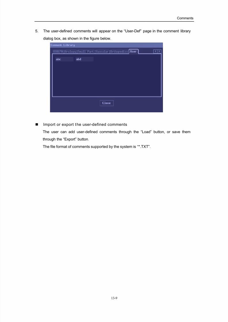
7/16/2019 DC-6 Operation Manual Basic CE V1.1
http://slidepdf.com/reader/full/dc-6-operation-manual-basic-ce-v11 97/149
Comments
13-9
5. The user-defined comments will appear on the “User-Def” page in the comment library
dialog box, as shown in the figure below.
Import or export the user-defined comments
The user can add user-defined comments through the “Load” button, or save them
through the “Export” button.
The file format of comments supported by the system is “*.TXT”.

7/16/2019 DC-6 Operation Manual Basic CE V1.1
http://slidepdf.com/reader/full/dc-6-operation-manual-basic-ce-v11 98/149
14-1
14Body Marks
The body marks are used for indicating the exam position of patient and probing
position and orientation of a transducer, served as additional explanation for an image.
14.1 Entering/Exiting Body Mark Mode
To enter the body mark mode, press the key to enter the body mark selection
mode.
To exit the body mark mode:
In the body mark mode, press『Body Mark』again or the『Exit』key to confirm the current
operation and exit the body mark mode.
14.2 Categories of Body Marks
The body marks are grouped into different categories: Abdomen, OB/GYN, Cardiology,
Small Part, Blood Vessel, Urology, and Orthopedics. Each category consists of multiple
body marks, and the user can select body marks or preset them in the exam modes as
required.

7/16/2019 DC-6 Operation Manual Basic CE V1.1
http://slidepdf.com/reader/full/dc-6-operation-manual-basic-ce-v11 99/149
Body Marks
14-2
14.3 Body Mark Menu
In the body mark mode, pressing the『Menu』key can open or hide the body mark menu.
Through the body mark menu the user can open each category of the body marks or
set the body mark function. The body mark menu is shown in the figure below:
The body mark setups are explained as follows:
Current body mark
The current body mark has two statuses, i.e., “1st” and “2nd”, and the “1st” status is
default. To add two body marks on an image at the same time, the user needs to set the
“Current BM” to “2nd”; otherwise the user cannot add the second body mark on the
image.
Display
The user can display or hide the added body marks on the image.

7/16/2019 DC-6 Operation Manual Basic CE V1.1
http://slidepdf.com/reader/full/dc-6-operation-manual-basic-ce-v11 100/149
Body Marks
14-3
14.4 Adding Body Marks
The system allows the user to add a body mark to an image, or to add two body marks
to one image window. To add two body marks to one image window, first set the current
body mark status to “2nd” through the body mark menu. Refer to “Body Mark Menu”
section for details.
The operation will be described by the following procedures of adding one body mark to
an image.
1. Select a body mark: in the body mark mode, move the cursor on the desired body
mark, and the body mark becomes bright and with its frame highlighted (as shown
in the figure below). Click “ ” or “ ”, or turn the multifunction knob, and the
user can look for the body marks of one category in different pages. When there isonly one page, the user cannot turn pages. Pressing the『change』key can switch
between different categories.
2. Confirm a body mark: press the『Set』key to confirm the body mark added.
3. Adjust the position and orientation of the transducer symbol: roll the trackball to
place the transducer symbol in the correct position; turn the multifunction knob to
adjust the orientation.
4. Press the『Set』key to confirm the position and orientation of the transducer symbol
and exit the body mark mode at the same time.
7/16/2019 DC-6 Operation Manual Basic CE V1.1
http://slidepdf.com/reader/full/dc-6-operation-manual-basic-ce-v11 101/149
Body Marks
14-4
14.5 Moving Body Marks
The user can move the added body marks to any desired position on the image.
1. Roll the trackball to move the cursor onto an added body mark, and the cursor
becomes “ ”, indicating the user can select this body mark.
2. Click the『Set』key to select the body mark, and a frame appears around the body
mark.
3. Move the cursor to the desired position, and the body mark moves along with the
cursor.
4. Click the『Set』key to confirm the new position, and the operation of moving the
body mark is complete.
NOTE:
In B+B mode, bodymarks cannot be moved between image windows.
14.6 Deleting Body Marks
To delete an added body mark in the image window, perform the procedures as follows:
1. Click the『Set』key to select a body mark to delete, and press the『Clear 』key to
delete the selected body mark.
NOTE: In the body mark mode, if no object is selected, pressing the 『Clear 』 key will clear
all comments and general measurements.
2. In the body mark mode, pressing the『Back』key can delete the added body marks
one by one.
3. In the body mark selection status, if the user doesn’t add any body mark, pressing
the『Body Mark』key can exit the body mark mode.

7/16/2019 DC-6 Operation Manual Basic CE V1.1
http://slidepdf.com/reader/full/dc-6-operation-manual-basic-ce-v11 102/149
Body Marks
14-5
14.7 Body Mark Preset
In order to adapt operation habits and clinical practice needs of different users, the
system supports the preset function for body marks. This function is to preset the
relevant parameters of body marks, preset body marks in each exam mode, and define
body marks.
Preset position of body mark
The user can enter the “General” page in the “System Preset” screen through the preset
menu, to modify the setup in the “Body Mark and Comment” field (as shown in the figure
below). The user can set the position where a body mark appears on the image.
Preset desired body marks for an exam mode
1. Select the “Body Mark Preset” item in the preset menu or exam mode setup
screen and enter the body mark preset dialog box (as shown in the figure below).
2. Select the exam mode that you will preset the body mark, and click the
drop-down menu to select the exam mode.
3. Click to select the desired body mark on the “Available Items”. If the desired body
mark is not found, open the “Anatomic App.” drop-down menu, to select other
anatomical regions for corresponding body mark sets, and to search the desired
body mark.

7/16/2019 DC-6 Operation Manual Basic CE V1.1
http://slidepdf.com/reader/full/dc-6-operation-manual-basic-ce-v11 103/149
Body Marks
14-6
4. Select the desired body mark, and click “ ” to add it to the column on the
right side.
5. The user can arrange the order of the selected body marks in the column on the
right side, through the “Up” or “Down” button.
Define body marks
If there is no body mark desired in the library, the user can define the body marks. In the
body mark preset dialog box above, click “ ’ to enter the user-defined dialog
box (as shown in the figure below).
The user can edit, delete or export the user-defined body marks, or add body marks
through drawing or importing. The method of importing and exporting is similar to that in
the file system. The file format is *.BIN. The following is only to introduce the manual
edit of body marks.

7/16/2019 DC-6 Operation Manual Basic CE V1.1
http://slidepdf.com/reader/full/dc-6-operation-manual-basic-ce-v11 104/149
Body Marks
14-7
The procedures of adding user-defined body marks are described as follows:
2. Click the “Add” button on the screen to enter the creation selection screen of body
marks,and the user can select to copy an existing body mark or draw a new body
mark.
3. Click [Copy] or [Add] button. The drawing screen is shown as follows:

7/16/2019 DC-6 Operation Manual Basic CE V1.1
http://slidepdf.com/reader/full/dc-6-operation-manual-basic-ce-v11 105/149
Body Marks
14-8
4. The drawing tools are described as follows:
5. The user can select “ ” on the screen, to adjust position of the transducer
indicator on the body mark and rotate the multi-functional knob to change direction
of the indicator.
6. After the drawing of a body mark is complete, click [OK] to save it and exit the
user-defined body mark status.
Left/right reverseUp/down reverse
Brush Eraser
Zoom in Zoom out
Rotate Drag
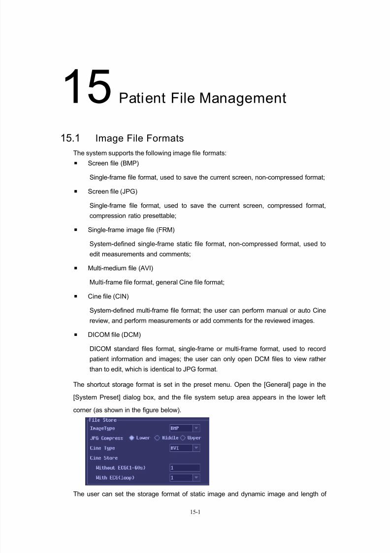
7/16/2019 DC-6 Operation Manual Basic CE V1.1
http://slidepdf.com/reader/full/dc-6-operation-manual-basic-ce-v11 106/149
15-1
15Patient File Management
15.1 Image File Formats
The system supports the following image file formats:
Screen file (BMP)
Single-frame file format, used to save the current screen, non-compressed format;
Screen file (JPG)
Single-frame file format, used to save the current screen, compressed format,
compression ratio presettable;
Single-frame image file (FRM)
System-defined single-frame static file format, non-compressed format, used to
edit measurements and comments;
Multi-medium file (AVI)
Multi-frame file format, general Cine file format;
Cine file (CIN)
System-defined multi-frame file format; the user can perform manual or auto Cine
review, and perform measurements or add comments for the reviewed images.
DICOM file (DCM)
DICOM standard files format, single-frame or multi-frame format, used to record
patient information and images; the user can only open DCM files to view rather
than to edit, which is identical to JPG format.
The shortcut storage format is set in the preset menu. Open the [General] page in the[System Preset] dialog box, and the file system setup area appears in the lower left
corner (as shown in the figure below).
The user can set the storage format of static image and dynamic image and length of

7/16/2019 DC-6 Operation Manual Basic CE V1.1
http://slidepdf.com/reader/full/dc-6-operation-manual-basic-ce-v11 107/149
Patient File Management
15-2
Cine files, and set the compression rate of JPEG image files.
NOTE: The compression of JPEG may result in image distortion.
15.2 Stor ing Image Files
During the process of examining a patient, the user can directly store the exam images
to the patient database for image review.
To quickly store images in the unfrozen status, the method is described as follows:
Pressing the key can store the current single-frame image file in the default file
directory in the static image format (BMP, JPEG or FRM), and the file is stored in thedefault filename.
After freezing, pressing the key can store the current image file in the default
directory in the dynamic image format (CIN or AVI), and the file is stored in the default
filename.
To store a file by manually naming the file, the method is described as follows:
Press the 『Freeze』 key to freeze the image, and press the『Menu』key to open the
menu, and select the [Image Data Save] item to open the storage dialog box, as shown
in the figure below:
The user can change storage path, set storage format and name the file to store the
image file.
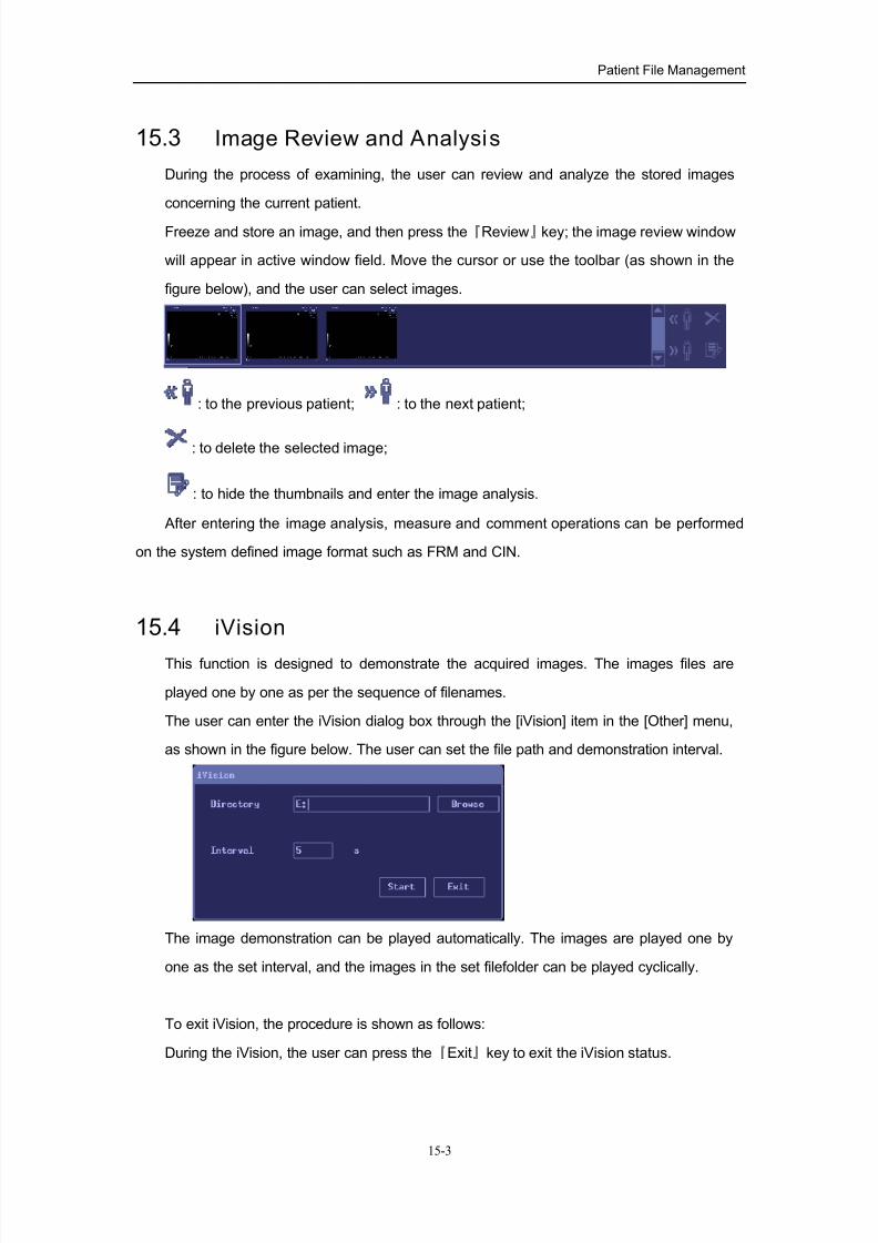
7/16/2019 DC-6 Operation Manual Basic CE V1.1
http://slidepdf.com/reader/full/dc-6-operation-manual-basic-ce-v11 108/149
Patient File Management
15-3
15.3 Image Review and Analysis
During the process of examining, the user can review and analyze the stored images
concerning the current patient.
Freeze and store an image, and then press the『Review』key; the image review window
will appear in active window field. Move the cursor or use the toolbar (as shown in the
figure below), and the user can select images.
: to the previous patient; : to the next patient;
: to delete the selected image;
: to hide the thumbnails and enter the image analysis.
After entering the image analysis, measure and comment operations can be performed
on the system defined image format such as FRM and CIN.
15.4 iVision
This function is designed to demonstrate the acquired images. The images files are
played one by one as per the sequence of filenames.
The user can enter the iVision dialog box through the [iVision] item in the [Other] menu,
as shown in the figure below. The user can set the file path and demonstration interval.
The image demonstration can be played automatically. The images are played one by
one as the set interval, and the images in the set filefolder can be played cyclically.
To exit iVision, the procedure is shown as follows:
During the iVision, the user can press the『Exit』key to exit the iVision status.

7/16/2019 DC-6 Operation Manual Basic CE V1.1
http://slidepdf.com/reader/full/dc-6-operation-manual-basic-ce-v11 109/149
Patient File Management
15-4
15.5 Search Patient
Press the『iStation』key or click In the “Patient Info” screen to open “iStation”
screen, as shown in the figure below:
To inquire patient information, the procedures are described as follow:
1. Confirm data source: select the database position, such as internal hard disk.
2. Set the filtering conditions: ID, patient name, exam date (clicking can
quickly set the date as “Today”).
3. Click , and the system will start to search patient data according to the set
conditions.
4. To change the inquired conditions, click to reset the conditions.

7/16/2019 DC-6 Operation Manual Basic CE V1.1
http://slidepdf.com/reader/full/dc-6-operation-manual-basic-ce-v11 110/149
Patient File Management
15-5
15.6 iStation
The user can press the 『iStation』key or “Search” button to enter the “iStation” (as
shown in the figure below). And the user can manage the patient data (including images
and reports) through the buttons on the right side of the screen.
The user can perform operations of Info, Select All, Delete, Export for patients’ items.
The images and reports of the selected patient items are shown below the patient list,
and the user can perform operations of Select All, Save As, and Delete.
The operation buttons for patient data are located on the right side of the patient list,
and their functions are described as follows:
【Info】 : to view patient basic information.
【Select All】 : to select all patient data.
【Delete】 : to delete the selected patient data.
【Export】 : to export the selected patient data to other memory location.
The operation buttons for images and reports are located on the lower right side of the
screen, and their functions are described as follows:
【Select All】 : to select all images or reports in the list.
【Save As】 : to save the selected data to another place.
【Delete】 : to delete the selected images or reports.

7/16/2019 DC-6 Operation Manual Basic CE V1.1
http://slidepdf.com/reader/full/dc-6-operation-manual-basic-ce-v11 111/149
Patient File Management
15-6
15.7 Disk Management
The disk management function is designed to manage the directories and files saved in
disks.
The user can enter the “File Manager” dialog box through the [File Manager] item in the
[Other] menu, as shown in the figure below:
15.7.1 Directory management
The directory management function is designed to create, rename, copy (can’t be
overwrited) or delete a directory.
To create a directory:
1. Select a drive to create the directory in the drop-down list box, and then select
directory position for creating the directory.
2. Move the cursor onto the「Create」button in the dialog box, and press the『Set』
key. The directory-creating dialog box pops up.
3. Enter the directory name in the dialog box, and click「OK」to close the dialog box,
and the created directory is added in the directory list box. Or click the「
Cancel」
button, and the operation of creating the directory is cancelled.
To rename a di rectory:
1. Select the drive of the selected directory in the drive list box.
2. Select the directory to be renamed in the directory list.
3. Click「Rename」, and the Rename dialog box pops up.
4. Enter the new name for the directory, and click [OK] to close the dialog box, and
the name of the directory is updated in the directory list box. Or click the 「Cancel」
button to cancel the operation of renaming the directory.

7/16/2019 DC-6 Operation Manual Basic CE V1.1
http://slidepdf.com/reader/full/dc-6-operation-manual-basic-ce-v11 112/149
Patient File Management
15-7
To delete a directory:
1. Select the drive of the directory in the drive list box.
2. Select the directory to be deleted in the directory list.
3. Click the「Delete」button, and the directory-deleting dialog box pops up.
4. Click the「OK」button to close the dialog box, and the directory is deleted from the
directory list box. Or click the「Cancel」button to cancel the operation of deleting the
directory.
15.7.2 File management
The file management function is designed to rename, delete or copy files, or delete all
files in the current directory.
To rename a file:
1. Select the drive and directory of the file to be renamed.
2. Select the file to be renamed in the file list, and click the「Rename」button, and the
file-renaming dialog box pops up.
3. Enter the new name for the file in the dialog box, and click the「OK」button to
confirm the new name, or click the「Cancel」button to cancel this operation.
To delete a file:
1. Select the drive and directory of the file to be deleted.
2. Select the file to be deleted in the file list, and click the「Delete」button, and the
file-deleting dialog box pops up.
3. Click the「OK」button in the dialog box to confirm the deletion, or click the「Cancel」
button to cancel this operation.
To copy or paste a file:
1. select the file to be copied, and move the cursor onto the「Copy」button to confirm.
2. Select and enter the directory of the file to be copied, and move the cursor onto the[Paste] button, and press the『Set』key to start the file coping operation. After the
coping is complete, the copied file appears in the directory.
3. If there is a file with the same filename existing in the directory, the system will pop
up a dialog box to prompt “The file has existed, are you sure to overwrite it?” The
user can select to click “OK” or “Cancel” to confirm if the file is overwritten.

7/16/2019 DC-6 Operation Manual Basic CE V1.1
http://slidepdf.com/reader/full/dc-6-operation-manual-basic-ce-v11 113/149
Patient File Management
15-8
15.7.3 CD file management
The system supports writing data in CD and reading data from CD.
Click the [Burn] button on the [File Manager] screen to enter the CD backup operation,
and the system pops up the dialog box as follows:
To back up data, the procedures are described as follows:
1. Put a rewritable CD in the CD-RW drive.
NOTE: if you want to rewrite a CD which has data in it, please erase the data first and
then rewrite it. To erase a CD, you can start the erasing operation through the [Erase]
button on the backup screen.
2. Select a drive: select a drive in the drop-down list and double-click it.
3. Select the file folder or directory on the left side of the screen, click “ ” to add
it the box where the files to be backed up are listed on the right side of the screen.
To cancel the selected file, click “ ” after the file is selected. To cancel all
selected files, click “ ”.
Note: when the directory is more than 6 levels, the files cannot be backed up.
4. After the files are selected, the user can see the CD space occupied, free space,
and total space. The total capacity of the selected files cannot exceed the CD
capacity.
5. Click the [Burn] button, and the backup operation begins.
6. After the backup is complete, the screen will display information of writing
successfully, and the CD automatically ejects out.
NOTE: During backup process, if a CD is forcibly taken out or the user performs other
operations, the backup may fail or the system may malfunction.
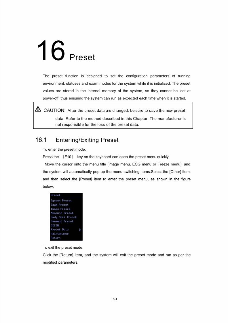
7/16/2019 DC-6 Operation Manual Basic CE V1.1
http://slidepdf.com/reader/full/dc-6-operation-manual-basic-ce-v11 114/149
16-1
16Preset
The preset function is designed to set the configuration parameters of running
environment, statuses and exam modes for the system while it is initialized. The preset
values are stored in the internal memory of the system, so they cannot be lost at
power-off, thus ensuring the system can run as expected each time when it is started.
CAUTION: After the preset data are changed, be sure to save the new preset
data. Refer to the method described in this Chapter. The manufacturer is
not responsible for the loss of the preset data.
16.1 Entering/Exiting Preset
To enter the preset mode:
Press the 『F10』 key on the keyboard can open the preset menu quickly.
Move the cursor onto the menu title (image menu, ECG menu or Freeze menu), and
the system will automatically pop up the menu-switching items.Select the [Other] item,
and then select the [Preset] item to enter the preset menu, as shown in the figure
below:
To exit the preset mode:
Click the [Return] item, and the system will exit the preset mode and run as per the
modified parameters.

7/16/2019 DC-6 Operation Manual Basic CE V1.1
http://slidepdf.com/reader/full/dc-6-operation-manual-basic-ce-v11 115/149
Preset
16-2
16.2 System Preset
The system preset contains several tab sheets, i.e., Local, General, System, Meas
Param, Biopsy, Other and Sys Info.
To confirm the modified parameters, click [Ok]. To cancel the modified parameters, click
[Cancel]. Clicking the [Load Factory] button can restore the current page to the factory
setups. The content of each page will be described as follows.
Local
The Local page is to preset hospital name, language, time zone, and time format. For
the hospital name, the user needs to enter relevant information; for others, the user can
select through options or drop-down menus.
General
The General page is divided into severral areas, i.e., Patient Information, File Access,
System Dormancy, and Bodymark and Comment.
System
The System page is used for ECG-relevant setups and format setups of image display
information.
Meas param
The measurement parameter page is used for setup of measurement unit, general
measurements, calculation, volume and reports.
Biopsy
The Biopsy screen is used for default bracket setups and type setups of biopsy guide
lines.
Other
The Other screen is to preset the default setups of peripheral devices (such as printer,
VCR) and some setups of main panel such as key volume, lightness and trackball
flexibility. Additionally the screen can be used to open the user-defined dialog box to set
the blank keys on the minor panel and some F functional keys on the keyboard.
Click the button to enter the dialog box shown in the figure below,
and set the reserved keys on the keyboard as shortcut keys.
The method for setting the user-defined keys is described as follows:
1. Click “Key Function” to select which key the user wants to set user-defined
function;
2. Move the cursor to the “Category” column to select the function category for the
shortcut keys to be set (such as VCR, output, measurement, image);

7/16/2019 DC-6 Operation Manual Basic CE V1.1
http://slidepdf.com/reader/full/dc-6-operation-manual-basic-ce-v11 116/149
Preset
16-3
3. Select the specific functions of the set category;
4. Click [OK] to confirm the newly-defined setup, or click [Cancel] to cancel the
newly-defined setup.
System Infomation
The “Sys Info” screen contains the version information of system software and other
modules. The user cannot edit the information, but can only view it. The information
varies with the system configuration and version, so it depends on the system
purchased.
16.3 Exam Mode Preset
Refer to “9.3 Presetting Exam Modes ”.
16.4 Image Parameter PresetRefer to “10.4 Image Parameter Preset”.
16.5 Comment Preset
Refer to “13.7 Comment Preset”.
16.6 Body Mark Preset
Refer to “14.7 Body Mark Preset”.

7/16/2019 DC-6 Operation Manual Basic CE V1.1
http://slidepdf.com/reader/full/dc-6-operation-manual-basic-ce-v11 117/149
Preset
16-4
16.7 Measurement Preset
Refer to “Measurement Preset” in the [Advanced Volume] of the operation manual.
16.8 Preset DataOpen the “Preset Data” submenu in the preset menu, and the user can select the [Save],
[Load] or [Default]. Thus the user can save new preset data, load existing preset data or
restore the factory setups.
16.8.1 Save preset data
This function is used to write all preset data by the user to a disk. The format of the data
file is DTA.
The procedures are described as follows:1. Move the cursor onto the [Save] item and press the『Set』key. The screen pops up
the dialog box of saving files.
2. Select the driver, change the path and enter the filename.
3. Click「OK」, and the dialog box closes. The system automatically saves the preset
data to the specified file.
16.8.2 Load preset data
This function is used to load the existing preset data to the preset data memory of the
system, and the system resets and runs as per the changed preset data.The procedures are described as follows:
1. Move the cursor onto the [Load] item and press the『Set』key. The screen pops up
the dialog box of opening files.
2. Select the preset data file and open it.
3. After the preset data file is opened, the system exits the file status. The system
resets and organizes the image display as per the changed preset data.
16.8.3 Load factory
Move the cursor onto the [Default] item and press the『Set』key. The screen pops up the
dialog box. Click the「OK」button, and the system will restore the factory setups. Click
the「Cancel」button, and the system will cancel the restoration of the factory setups.
16.9 Maintenance
The [Maintenance] item is designed for the user to update the system software or other
special functions. If the user requires these functions, please contact Mindray
representatives.

7/16/2019 DC-6 Operation Manual Basic CE V1.1
http://slidepdf.com/reader/full/dc-6-operation-manual-basic-ce-v11 118/149
17-1
17Biopsy Guide
17.1 Entering or Exiting Biopsy Menu
Move the cursor onto the menu title and the expanded list appears; select the [Biopsy]
item from the list to open the biopsy menu, as shown in the figure below.
Press the『Exit』key or switch to another menu, and the system exits the biopsy menu.
WARNING: Do not freeze an image while performing b iopsy procedure.
17.2 Displaying Biopsy Guide Lines1. Select biopsy bracket
To display biopsy guide lines, first specify the model of the biopsy bracket used with
the current transducer. Select the model of the biopsy bracket through the item of the
[Bracket].
2. Display or hide the guide line
To display the guide line of the current bracket, press the『Set』key on [Display] to
adjust the status to “On”. To hide the guide line, adjust the status to “Off”.
3. Select linetype
Roll the trackball to move the cursor on [Linetype] , and click the『Set』 or 『Back』
key to switch among linetypes of biopsy guide lines, i.e., “Large”, “Medium”, or
“Small”.

7/16/2019 DC-6 Operation Manual Basic CE V1.1
http://slidepdf.com/reader/full/dc-6-operation-manual-basic-ce-v11 119/149
Biopsy Guide
17-2
17.3 Verifying the Biopsy Guide line
WARNING:
1. Prior to each biopsy procedure, be sure to verify the guide line.
2. If the needle is not consis tent with the guide line, do not perform
the biopsy procedure.
NOTE: If the B-mode image isn’t displayed in the real-time status, you cannot verify the
guide line.
Click [Verify] to open the Verify menu.
Adjust position
Through the [Position] item in the Verify menu, the user can move the guide line
horizontally.
Move the cursor on [Position] , and press the『Set』key to increase the value or
press the『Back』key to decrease the value.
Adjust angle
Through the [Angle] item, the user can adjust the angle of the guide line. The
method is identical to that of adjusting “Position”.
Save verified settings
After the position and angle of the guide line are adjusted, click [Save], and the
system will save the current data of the guide line. When the system is restarted
next time, the position and angle of the guide line are those verified.
Restore the factory default settings
Click [Load Default], the position and angle of the guide line will restore the factory
default settings.
Exit the Verify status
Click [Exit], and the system will exit the verification status of the guide line.
7/16/2019 DC-6 Operation Manual Basic CE V1.1
http://slidepdf.com/reader/full/dc-6-operation-manual-basic-ce-v11 120/149
18-1
18ECG
The system can be configured with the optional ECG module. In that case, the ECG
signals can be displayed on the image in real time. This ECG module only provides
physiological signals for reference rather than for monitoring. Operaters shall take care.
The ECG signal is displayed on the image, and can be reviewed with the image after
the image is frozen.
WARNING:
1. To avoid electric shock, the following checks shall be performed
prior to an operation:
The ECG electrode shall not be abnormal (abnormalities refer to
damage or crack of the electrode and cable);
The ECG electrode shall be correctly connected;
The user should use the ECG leadwire provided with the ECG
module. Otherwise it may result in electric shock.
2. Only after the ECG cable is connected to the system, can the ECG
electrode be placed on the patient’s body. Otherwise, the patient
may be subject to electric shock.
3. Don’t place the ECG electrodes directly to contact the patient’s
heart; otherwise it may lead to stop of the patient’s heartbeat.
4. When the voltage applied on the body surface of the patient
exceeds 15V, be sure to remove the ECG electrode from the patient,
in order to prevent electric shock.
5. Before using high frequency electric surgical unit, high frequency
therapeutic equipment or defibrillator, be sure to remove the ECG
electrode from the patient, in order to prevent electric shock.
6. Conductive parts of electrodes and associated connectors for ECG
should not con tact other conductive parts including earth.
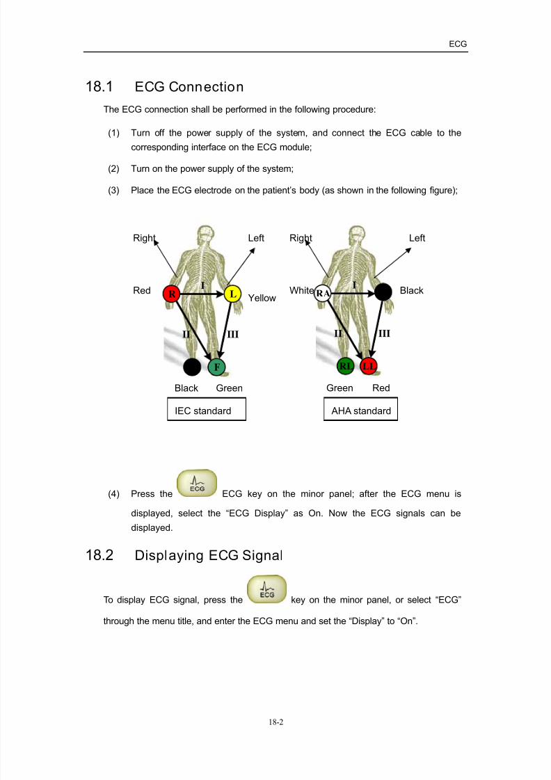
7/16/2019 DC-6 Operation Manual Basic CE V1.1
http://slidepdf.com/reader/full/dc-6-operation-manual-basic-ce-v11 121/149
ECG
18-2
18.1 ECG Connection
The ECG connection shall be performed in the following procedure:
(1) Turn off the power supply of the system, and connect the ECG cable to thecorresponding interface on the ECG module;
(2) Turn on the power supply of the system;
(3) Place the ECG electrode on the patient’s body (as shown in the following figure);
(4) Press the ECG key on the minor panel; after the ECG menu is
displayed, select the “ECG Display” as On. Now the ECG signals can be
displayed.
18.2 Displaying ECG Signal
To display ECG signal, press the key on the minor panel, or select “ECG”
through the menu title, and enter the ECG menu and set the “Display” to “On”.
I
II III
N F
LRI
II III
RA LA
LLRL
IEC standard AHA standard
RedYellow
GreenBlack
Black
Green Red
White
LeftRightLeftRight

7/16/2019 DC-6 Operation Manual Basic CE V1.1
http://slidepdf.com/reader/full/dc-6-operation-manual-basic-ce-v11 122/149
19-1
19VCR
VCR is used to record and replay images during the ultrasound exams. The memory
medium of the VCR recorder is cassette.
NOTE: 1. Strictly observe the procedures described here to perform the recording
and replaying operations of VCR; otherwise it may result in data loss o r
system malfunction.
2. The video system (PAL or NTSC) shall be cons istent with the recording
system of the device.
3. The recording may not be successful due to accidents, so regarding
important data, please check if the images are successfully recorded
while recording is complete. Mindray is not responsible for data loss.
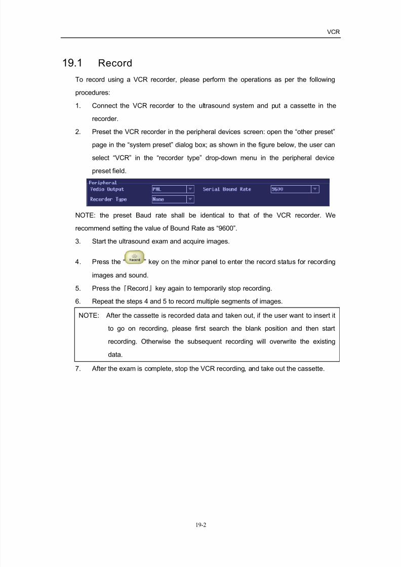
7/16/2019 DC-6 Operation Manual Basic CE V1.1
http://slidepdf.com/reader/full/dc-6-operation-manual-basic-ce-v11 123/149
VCR
19-2
19.1 Record
To record using a VCR recorder, please perform the operations as per the following
procedures:
1. Connect the VCR recorder to the ultrasound system and put a cassette in the
recorder.
2. Preset the VCR recorder in the peripheral devices screen: open the “other preset”
page in the “system preset” dialog box; as shown in the figure below, the user can
select “VCR” in the “recorder type” drop-down menu in the peripheral device
preset field.
NOTE: the preset Baud rate shall be identical to that of the VCR recorder. We
recommend setting the value of Bound Rate as “9600”.
3. Start the ultrasound exam and acquire images.
4. Press the “ ” key on the minor panel to enter the record status for recording
images and sound.
5. Press the『Record』key again to temporarily stop recording.
6. Repeat the steps 4 and 5 to record multiple segments of images.
NOTE: After the cassette is recorded data and taken out, if the user want to insert it
to go on recording, please first search the blank position and then start
recording. Otherwise the subsequent recording will overwrite the existing
data.
7. After the exam is complete, stop the VCR recording, and take out the cassette.

7/16/2019 DC-6 Operation Manual Basic CE V1.1
http://slidepdf.com/reader/full/dc-6-operation-manual-basic-ce-v11 124/149
VCR
19-3
19.2 Replay
To replay the recorded images using VCR, please perform the operations as per the
following procedures:
1. Connect the VCR recorder to the system and put the cassette in the recorder.
2. Check preset: “recorder type” is set to VCR.
3. Press the F9 key on the keyboard to enter the VCR replay status, and open the
replay menu as follows:
Some menu items are to be introduced as follows:
[Viss]: segment index, set for searching between segments;
[Viss Mark]: to insert the segment mark in the current image position;
[Search/Counter]: to search and set the VCR counter;
[Search Blank]: to search a cassette to find the next blank position;
[Eject]: to stop the VCR replay (but not to exit the VCR replay status), to eject the
cassette.
4. Click [Play/Pause]: to play the recorded images; click it again to temporarily stop
playing.
5. Press the F9 key again or click the [exit] item on the menu to exit the VCR replay
status.
7/16/2019 DC-6 Operation Manual Basic CE V1.1
http://slidepdf.com/reader/full/dc-6-operation-manual-basic-ce-v11 125/149
20-1
20System Maintenance
The system maintenance shall be completed by users and Mindray service engineers,
but the users will take all responsibilities for the maintenance and operation after the
system is purchased.
WARNING: Only the professional engineers can perform the maintenance
not specified in this manual. However, you can contact your Mindray service representative.
20.1 Daily Maintenance
The user shall conduct the daily maintenance.
20.1.1 Cleaning the system
WARNING: Before cleaning the system, be sure to turn of f the power and
disconnect the power cable from the outlet. If you clean the
system while the power is “ On”, it may result in electric shock.
1. Cleaning the transducer
Please refer to the operation manual of the corresponding transducer to perform
cleaning, disinfection and sterilization.
2. Cleaning the transducer socket
(a) Use soft dry cloth to erase the stains of the socket.
(b) If it is difficult to clean the stains thoroughly, use soft cloth dipped with mild
detergent, and then make it air-dried.
3. Cleaning the monitor
Use the soft cloth dipped with glass detergent to erase the monitor, and then make
it air-dried.
NOTE: Do not use hydrocarbon glass cleaner or the cleaner for the OA equipment to clean
the monitor. These substances may cause deterioration of the monitor.

7/16/2019 DC-6 Operation Manual Basic CE V1.1
http://slidepdf.com/reader/full/dc-6-operation-manual-basic-ce-v11 126/149
System Maintenance
20-2
4. Method for cleaning the main panel, shell and bracket
Use dry soft cloth to clean the surface of the system. If the system is dirty, moisten
the soft cloth with the neutral detergent and wipe off any stains. And then use the
dry soft cloth to wipe off moisture from the system or make it air-dried.
5. Cleaning the trackball
a)Disassembling the trackball
Press the bulges on the clamping ring by both hands and turn the ring about
45° clockwise until it lifts. Take out the ring and the rotary ball. Be careful not
to drop the ball.
b)Cleaning the trackball
Clean the two long shafts, the bearing and the rotary ball with soft dry cloth
or paper.
c)Installing the trackball
Put the rotary ball back in the trackball and then align the clamping ring click
with the top cover notch. Press the bulges on the ring with both hands and
turn the ring about 45° counterclockwise until the ring clicks. As the bulges
are flush with the top cover, the ring is secured.
Top cover
Rotary ball
Clamping ring

7/16/2019 DC-6 Operation Manual Basic CE V1.1
http://slidepdf.com/reader/full/dc-6-operation-manual-basic-ce-v11 127/149
System Maintenance
20-3
20.1.2 Backup of the system hard disk
To prevent deterioration or loss of data stored in the system hard disk, create a backup
copy of the hard disk at appropriate time.
20.2 Maintenance Checks by Service Engineer
The following checks shall be performed to ensure the performance and safety of the
system. Contact your Mindray representative when carrying out these checks, since
special techniques are required to perform these checks.
Check category Check item
Cleaning Interior of the systemPeripheral units
Electric safety Protective conductor resistance
Earth leakage current
Enclosure leakage current
Patient leakage current
Patient leakage current (110% mains on applied
part)
Patient auxiliary leakage current
Mechanical safety CastersCaster mounting sectionsMonitor mounting mechanismMain panelMounting mechanism for the peripheral devicesOther mechanical partsExternal appearance of the transducer
Image recording Images in each modeImage recording by using the standardtransducer

7/16/2019 DC-6 Operation Manual Basic CE V1.1
http://slidepdf.com/reader/full/dc-6-operation-manual-basic-ce-v11 128/149
System Maintenance
20-4
20.3 Consumable Parts and the Parts of Periodic
Replacement
This system contains some parts requiring periodic replacement and some consumableparts.
The consumable parts include casters and fuses, etc. For replacement, please contact
your Mindray representative for instructions.
20.4 Troubleshooting
To ensure the normal operation of the system, it is recommended to establish the
maintenance and inspection plan to periodically check the safety of the system. If any
abnormity is detected, contact the sales distributor of Mindray.
If there is an abnormality, e.g. after the start-up, there is no image, or there is menu but
no image, please check it up first by referring to the table below. If the failure cannot be
eliminated, please contact the sales distributor of Mindray.
CAUTION: 1. Do not spill w ater or other liquid into the system while you
perform the cleaning. Otherwise it may result in malfunction or
electric shock.
2. When user want to clean transducer connectors and TGC
sliders, contact the sales department of Mindray. Cleaning by
user self may result in malfunction or degradation of the
performance.
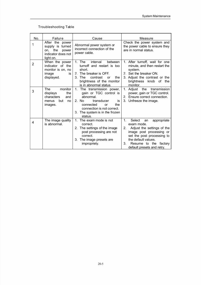
7/16/2019 DC-6 Operation Manual Basic CE V1.1
http://slidepdf.com/reader/full/dc-6-operation-manual-basic-ce-v11 129/149
System Maintenance
20-5
Troubleshooting Table
No. Failure Cause Measure
1 After the power supply is turned
on, the power indicator does notlight on.
Abnormal power system or
incorrect connection of thepower cable.
Check the power system andthe power cable to ensure they
are in normal status.
2When the power indicator of themonitor is on, noimage isdisplayed.
1. The interval betweenturnoff and restart is tooshort.
2. The breaker is OFF.3. The contrast or the
brightness of the monitor is in abnormal status.
1. After turnoff, wait for oneminute, and then restart thesystem.
2. Set the breaker ON.3. Adjust the contrast or the
brightness knob of themonitor.
3The monitor displays thecharacters and
menus but noimages.
1. The transmission power,gain or TGC control isabnormal.
2. No transducer isconnected or theconnection is not correct.
3. The system is in the frozenstatus.
1. Adjust the transmissionpower, gain or TGC control.
2. Ensure correct connection.
3. Unfreeze the image.
4The image qualityis abnormal.
1. The exam mode is notcorrect.
2. The settings of the imagepost processing are notcorrect.
3. The image presets areimpropriety.
1. Select an appropriateexam mode.
2. Adjust the settings of theimage post processing or set the post processing tothe default values.
3. Resume to the factorydefault presets and retry.
7/16/2019 DC-6 Operation Manual Basic CE V1.1
http://slidepdf.com/reader/full/dc-6-operation-manual-basic-ce-v11 130/149
21-1
21 Acoustic Output
This section of the operation manual applies to the overall system including the main
unit, transducers, accessories and peripherals. This section contains important safety
information for operators of the device, pertaining to acoustic output and how to control
patient exposure through use of the ALARA (as low as reasonably achievable) principle.
Also this section contains information regarding the acoustic output testing and the
real-time output display.
Read this information carefully before using the system.
21.1 Concerns with Bioeffects
Diagnostic ultrasound is recognized as being safe. In fact, there have been no reports of
injuries to patients caused by diagnostic ultrasound.
It cannot be stated categorically that ultrasound is 100% safe. Studies have revealed
that ultrasound with extremely high intensity is harmful to body tissues.
Diagnostic ultrasound technology has made a great leap forward during the last several
years. This rapid advance has generated concerns about the potential risk of bioeffects
when new applications or diagnostic technologies become available.
21.2 Prudent Use Statement
Although there are no confirmed biological effects on patients caused by exposures
from present diagnostic ultrasound instruments, the possibility exists that such biological
effects may be identified in the future. Thus ultrasound should be used in a prudent
manner to provide medical benefit to the patient. High exposure levels and long
exposure times should be avoided while acquiring necessary clinical information.

7/16/2019 DC-6 Operation Manual Basic CE V1.1
http://slidepdf.com/reader/full/dc-6-operation-manual-basic-ce-v11 131/149
Acoustic Output
21-2
21.3 ALARA Principle (As Low As Reasonably
Achievable)
It is required to practice ALARA when using ultrasound energy. Practicing ALARA
ensures that the total energy level is controlled below a low enough level at which
bioeffects are not generated while diagnostic information is being accumulated. The
total energy is controlled by output intensity and total radiation time. The output intensity
necessary for examinations differs depending on the patient and the clinical case.
Not all examinations can be performed with an extremely low level of acoustic energy.
Controlling the acoustic level at an extremely low level leads to low-quality images or
insufficient Doppler signals, adversely affecting the reliability of the diagnosis. However,
increasing the acoustic power more than necessary does not always contribute to an
increase in quality of information required for diagnosis, rather increasing the risk of
generating bioeffects.
Users must take responsibility for the safety of patients and utilize ultrasound
deliberately. Deliberate use of ultrasound means that output power of ultrasound must
be selected based on ALARA.
Additional information regarding the concept of ALARA and the possible bioeffects of
Ultrasound is available in a document from the AIUM (American Institute of Ultrasound
Medicine) title “Medical Ultrasound Safety”.
21.4 MI/TI Explanation
21.4.1 Basic knowledge of MI and TI
(1) Mechanical bioeffect and thermal bioeffect
The relationship of various ultrasound output parameters (frequency, acoustic pressure
and intensity, etc) to bioeffects is not fully understood presently. It is recognized that two
fundamental mechanisms may induce bioeffects. One is a thermal bioeffect with tissue
absorption of ultrasound, and another one is a mechanical bioeffect based on
cavitations. Thermal Index (TI) gives the relative index of temperature increase by
thermal bioeffect, and Mechanical Index (MI) gives the relative index of mechanical
bioeffect. TI and MI indices reflect instantaneous output conditions, so they do not
consider the cumulative effects of the total examination time. TI and MI models contain
practical simplifications to complex bioeffects interaction. Then the operator should be

7/16/2019 DC-6 Operation Manual Basic CE V1.1
http://slidepdf.com/reader/full/dc-6-operation-manual-basic-ce-v11 132/149
Acoustic Output
21-3
aware that the actual worst case temperature rise may be up to several times higher
than the displayed TI value.
MI (Mechanical Index):
The mechanical bioeffects are the result of compression and decompression of
insonated tissues with the formation of micro bubbles that may be referred to as
cavitations.
MI is an index that shows the possibility of the cavitations generation based on acoustic
pressure, and the value in which the peak-rarefactional acoustic pressure is divided by
the square root of the frequency. Therefore MI value becomes smaller when the
frequency is higher or the peak- rarefactional acoustic pressure is lower, it becomes
difficult to generate the cavitations.
Pr, α MI =
awf f × CMI
,
CMI = 1 (MPa / MHz )
For the frequency 1 MHz and the peak-rarefactional acoustic pressure 1 MPa, MI
becomes 1. It is possible to think MI to be one threshold of the cavitations generation.
Especially, it is important to keep MI value to be low when both gases and the soft
tissues exist together, for such as lung exposure in cardiac scanning and bowel gas in
abdominal scanning.
TI (Thermal Index):
TI is determined by the ratio of the total acoustic power to the acoustic power required
to raise the tissue temperature by 1 degree C. In addition, because the temperature
rises is greatly different according to tissue structures, TI is divided three kinds: TIS
(Soft-tissue Thermal Index), TIB (Bone Thermal Index) and TIC (Cranial-bone Thermal
Index).
TIS: Thermal index related to soft tissues, such as abdominal and cardiac applications.
TIB: Thermal index for applications, such as fetal (second and third trimester) or
neonatal cephalic (through the fontanel), in which the ultrasound beam passes
through soft tissue and a focal region is in the immediate vicinity of bone.
TIC: Thermal index for applications, such as pediatric and adult cranial applications, in
which the ultrasound beam passes through bone near the beam entrance into the
body.

7/16/2019 DC-6 Operation Manual Basic CE V1.1
http://slidepdf.com/reader/full/dc-6-operation-manual-basic-ce-v11 133/149
Acoustic Output
21-4
Although the output power is automatically controlled for the selected applications, high
TI values should be keep to a minimum or avoided in obstetric applications. WFUMB
(World Federation for Ultrasound in Medicine and Biology) guidelines: state that
temperature increase of 4 degree C for 5 min or more should be considered as
potentially hazardous to embryonic and fetal tissue.
(2) MI/TI
The smaller the MI/TI values, the lower the bioeffects.
21.4.2 MI/TI display
TI and MI values are displayed in real time in the lower part of the screen. The operator
should monitor these index values during examinations and insure that exposure time
and output values are maintained at the minimum amounts needed for effective
diagnosis.
Under different operating conditions, once there is a situation that a MI value is greater
than 1.0; the start point of displaying MI values is 0.4.
In the same way, once there is a situation that a TI value is greater than 1.0, the TI
value will be displayed and the start point is 0.4. The user can set which TI item is to be
displayed in the preset. Open the "B/THI" page in [Image Parameter] dialogue, and the
acoustic output setups appear, as shown in the figure below:
Here the user can preset TIC, TIB or TIS to be displayed, as well as the level of
acoustic power. Generally speaking, when a cranial exam is performed, TIC is preset to
be displayed only.
NOTE: If there is a value of MI or TI exceeds 1.0, user must be careful to practice
ALARA principle.
The display precision is 0.1.
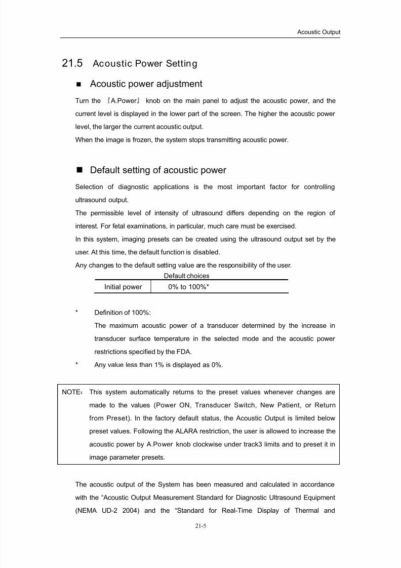
7/16/2019 DC-6 Operation Manual Basic CE V1.1
http://slidepdf.com/reader/full/dc-6-operation-manual-basic-ce-v11 134/149
Acoustic Output
21-5
21.5 Acoustic Power Setting
Acoustic power adjustment
Turn the 『 A.Power 』 knob on the main panel to adjust the acoustic power, and the
current level is displayed in the lower part of the screen. The higher the acoustic power
level, the larger the current acoustic output.
When the image is frozen, the system stops transmitting acoustic power.
Default setting of acoustic power
Selection of diagnostic applications is the most important factor for controlling
ultrasound output.
The permissible level of intensity of ultrasound differs depending on the region of
interest. For fetal examinations, in particular, much care must be exercised.
In this system, imaging presets can be created using the ultrasound output set by the
user. At this time, the default function is disabled.
Any changes to the default setting value are the responsibility of the user.
Default choices
Initial power 0% to 100%*
* Definition of 100%:
The maximum acoustic power of a transducer determined by the increase in
transducer surface temperature in the selected mode and the acoustic power
restrictions specified by the FDA.
* Any value less than 1% is displayed as 0%.
NOTE: This system automatically returns to the preset values whenever changes are
made to the values (Power ON, Transducer Switch, New Patient, or Return
from Preset). In the factory default status, the Acoustic Output is limited below
preset values. Following the ALARA restriction, the user is allowed to increase the
acoustic power by A.Power knob clockwise under track3 limits and to preset it in
image parameter presets.
The acoustic output of the System has been measured and calculated in accordance
with the “Acoustic Output Measurement Standard for Diagnostic Ultrasound Equipment
(NEMA UD-2 2004) and the “Standard for Real-Time Display of Thermal and

7/16/2019 DC-6 Operation Manual Basic CE V1.1
http://slidepdf.com/reader/full/dc-6-operation-manual-basic-ce-v11 135/149
Acoustic Output
21-6
Mechanical Indices on Diagnostic Ultrasound Equipment (AIUM and NEMA UD-3 2004).
21.6 Acoustic Power Control
The qualified operator may use the system controls to limit the ultrasound output and to
adjust the quality of the images. There are three categories of system controls relative
to output. They are (1.) Controls that have direct effect on the output, (2.) Controls that
indirectly control output and (3.) Controls that are receiver controls
Direct Controls:
It is possible to control, if necessary, the acoustic output with toggle switch “Acoustic
Power” on the operation panel. In this case, the maximum value of the acoustic output
never exceeds an MI of 1.9 and an ISPTA.3 of 720 mW/cm2
in any mode of operation.
Indirect Controls:
The controls that indirectly affect output are many imaging parameters. There are
operating mode, frequency, focal point and depth.
The operating mode determines whether ultrasound beam is scanning or
non-scanning. Thermal bioeffect is closely concerned with M, PW Doppler and Color
Doppler mode. Acoustic attenuation of tissue is directly related to transducer frequency.
The focal point is related to active aperture of transducer and beam width. For the
higher PRF (pulse repetition frequency), the more output pulses occur over a period of
time.
Receiver Controls:
The receiver controls (for example, gain, dynamic range, and enhance, etc.) do not
affect output. They should be used, if possible, to improve the image quality before
using controls that directly or indirectly affect output.

7/16/2019 DC-6 Operation Manual Basic CE V1.1
http://slidepdf.com/reader/full/dc-6-operation-manual-basic-ce-v11 136/149
Acoustic Output
21-7
21.7 Acoustic Output
21.7.1 Derated Ultrasonic Output Parameters
In order to determine the relevant Ultrasonic Output Parameters, a method is used
which allows for the comparison of ultrasound systems which operate at different
frequencies and are focused at different depths. This approach, called "derating" or
"attenuating", adjusts the acoustic output as measured in a water tank to account for the
effect of ultrasound propagation through tissue. By convention, a specific average
intensity attenuation value is used, which corresponds to a loss of 0.3 dB/cm/MHz.
That is, the intensity of ultrasound will be reduced by 0.3 dB/MHz for every centimeter of
travel from the transducer. This can be expressed by the following equation:
)10/3.0(10
z f
water attenc x I I ××
=-
Where Iatten is the attenuated intensity, Iwater is the intensity measured in a water tank
(at distance z), fc is the center frequency of the ultrasound wave (as measured in water),
and z is the distance from the transducer. The equation for attenuating pressure
values is similar except that the attenuation coefficient is 0.15 dB/cm/MHz, or one-half
the intensity coefficient. The intensity coefficient is double the pressure coefficient
because intensity is proportional to the square of pressure.
Although the attenuation coefficient chosen, 0.3 dB/cm/MHz, is significantly lower than
any specific solid tissue in the body, this value was chosen to account for fetal
examinations. In early trimester ultrasound fetal examinations, there may be a
significant fluid path between the transducer and the fetus, and the attenuation of fluid is
very small. Therefore the attenuation coefficient was lowered to account for this case.
21.7.2 Limits of acoustic output
In accordance with the FDA Track 3 requirements, the derating (or attenuated)
approach was incorporated into the FDA Acoustic Output Limits, as listed below. The
maximum acoustic output level from any transducer in any operating mode is expected
to fall below these limits.
FDA Maximum Acoustic Output Limits for Track 3 (Attenuated Values)
Application Ispta.3
(mW/cm2)
Isppa.3 (W/cm2) MI
All regions
(except eyes)720 ≤ 190
or
≤ 1.9

7/16/2019 DC-6 Operation Manual Basic CE V1.1
http://slidepdf.com/reader/full/dc-6-operation-manual-basic-ce-v11 137/149
Acoustic Output
21-8
21.7.3 Differences between actual and displayed MI and TI
In operation, the system will display to the operator the Acoustic Output Parameters
Thermal Index, TI, or Mechanical Index, MI (or sometimes both parameters
simultaneously). These parameters were developed as general indicators of risk from
either thermal or mechanical action of the ultrasound wave. They serve to indicate to
the operator whether a particular setting of the system increases or decreases the
possibility of Thermal or Mechanical effect. More specifically, they were designed to
assist in the implementation of the ALARA principle. As an operator changes a given
system control, the potential effect of the change in output will be indicated. However,
the Thermal Index is not the same as temperature rise in the body, for several reasons.
First of all, in order to provide a single display index to the user, a number of simplifying
assumptions had to be made. The biggest assumption was the use of the attenuating
formula described above, which is much lower that the actual value for most tissues
within the body. Scanning through muscle or organ tissue, for example, will produce
much higher attenuation than0.3 dB/cm/MHz. There were also significant simplifications
made for the thermal properties of tissue. Therefore, scanning through highly perfused
tissue, such as the heart or vasculature, will produce significantly less thermal effect
than that suggested by the Thermal Index.
Similarly, the Mechanical Index was derived to indicate the relative possibility of
mechanical (cavitation) effects. The MI is based on the derated peak rarefactional
pressure and the center frequency of the ultrasound wave. The actual peak
rarefactional pressure is affected by the actual attenuation caused by tissue in the path
between the transducer and the focal point. Again, all solid tissues within the body
have higher attenuation than the proscribed 0.3 dB/cm/MHz value, and therefore, the
actual peak rarefactional pressure will be lower. Further, the actual peak rarefactional
pressure will change depending upon the region of the body being scanned.
For these reasons, the TI and MI displays should only be used to assist the operator in
implementing ALARA at the time of the patient examination.

7/16/2019 DC-6 Operation Manual Basic CE V1.1
http://slidepdf.com/reader/full/dc-6-operation-manual-basic-ce-v11 138/149
Acoustic Output
21-9
21.8 Measurement Uncertainty
The total estimated measurement uncertainty (where the total uncertainty includes
the uncertainties in hydrophone response, measurement, calculation, and
positioning) are:
Ispta 32.9%
Isppa 32.9%
Center frequency (f c) 2%
Total power (W) 32.9 %
(5.1% for Scan-mode and Combined-mode)
Rarefactional pressure (pr) 16.4%
21.9 References for Acoustic Power and Safety
(1) “Bioeffects and Safety of Diagnostic Ultrasound” issued by AIUM in 1993
(2) “Medical Ultrasound Safety” issued by AIUM in 1994
(3) "Acoustic Output Measurement Standard for Diagnostic Ultrasound Equipment,
Revision 3" issued by AIUM/NEMA in 2004
(4) "Standard for real-time display of thermal and mechanical acoustic output indices
on diagnostic ultrasound equipment, Revision 2" issued by AIUM/NEMA in 2004
(5) "Information for Manufacturers Seeking Marketing Clearance of Diagnostic
Ultrasound Systems and Transducers" issued by FDA in 1997.
(6) “Medical electrical equipment – Part 2-37: Particular requirements for the safety
of ultrasonic medical diagnostic and monitoring equipment” issued by IEC in
2004.

7/16/2019 DC-6 Operation Manual Basic CE V1.1
http://slidepdf.com/reader/full/dc-6-operation-manual-basic-ce-v11 139/149
22-1
22Measurement Accuracy
Table 1 Error of two-dimensional images
Parameter Value range error
Depth Maximum 263 mm
Within +/- 3%; or when the measured
value is less than 40 mm, the error is
less than1.5 mm.
Area (Trace) Maximum 1038 cm2
Within +/- 7%; or when the measured
value is less than 16 cm2
, the error isless than 1.2 cm
2
Area (ellipse,
circle)Maximum 814cm2
Within +/- 7%; or when the measured
value is less than 16 cm2, the error is
less than 1.2 cm2
Angle 0~180° Within +/- 3%
% Stenosis Maximum 1.0 Within +/- 7%
Volume Maximum 999cm3
Within +/-10 %; or when the
measured value is less than 64 cm3,
the error is less than 6.4 cm3
Table 2 Time/Motion Measurements
Parameter Value range Error
Distance Maximum 263mm
Within +/-3 %; or when the measured
value is less than 40mm, the error is
less than 1.5mm
Time Maximum 8s Within +/- 1%
Heart rate15~999 beats per
minuteWithin +/- 4%
Slope (M mode) Maximum 999mm/s Within +/- 4%
Table 3 Doppler velocity measurement
Parameter Range error
Velocity 0.05~3.00m/s ≤±5%
NOTE: Within the selected field range, the measurement accuracy is ensured within the
range mentioned above. The accuracy specifications are performance in the
worst conditions, or based on the real test for the system, regardless of acoustic
speed error.

7/16/2019 DC-6 Operation Manual Basic CE V1.1
http://slidepdf.com/reader/full/dc-6-operation-manual-basic-ce-v11 140/149
23-1
23Safety Classification
(1) According to the type of protection against electric shock:
CLASS I EQUIPMENT
(2) According to the degree of protection against electric shock:
TYPE-BF EQUIPMENT
(3) According to the degree of protection against harmful ingress of water:
The main unit belongs to IPX0, and the transducers belong to IPX7.
Footswitch: 971 SWNOM belongs to IPX8.
(4) According to the degree of safety of application in the presence of a
FLAMMABLE ANESTHETIC MIXTURE WITH AIR or WITH OXYGEN OR
NITROUS OXIDE:
EQUIPMENT not suitable for use in the presence of a FLAMMABLE
ANESTHETIC MIXTURE WITH AIR or WITH OXYGEN OR NITROUS OXIDE
(5) According to the mode of operation:
CONTINUOUS OPERATION
(6) According to the installation and use:
MOBILE EQUIPMENT

7/16/2019 DC-6 Operation Manual Basic CE V1.1
http://slidepdf.com/reader/full/dc-6-operation-manual-basic-ce-v11 141/149
24-1
24Guidance and Manufacturer's
Declaration
The system complies with the EMC standard IEC60601-1-2: 2001+A1:2004.
WARNING: The use of unapproved accessories may diminish system
performance.
NOTE: 1. Use of accessories, transducers, and cables other than those specified may
result in increased emission or decreased immunity of system.
2. The system should not be used adjacent to or stacked with other equipment. If
adjacent or tacked use is necessary, system should be observed to verify
normal operation in the configuration in which it will be used.
3. The system needs special precautions regarding EMC and needs to be
installed and put into service according to the EMC information provided below.
4. Preventing conducted RF immunity. Due to technological limitations, theconducted RF immunity level are limited to 1Vrms level, conducted RF
interference above 1Vrms may cause wrong diagnosis and measurements. We
suggest that you position system further from sources of conducted RF noise.
5. Operation of system, in the case that the patient physiological signal is lower
than the minimum amplitude or value specified in the product specifications,
may cause inaccurate results.
6. Portable and mobile RF communications equipment can affects system. See
tables 1, 2, 3, and 4 below.

7/16/2019 DC-6 Operation Manual Basic CE V1.1
http://slidepdf.com/reader/full/dc-6-operation-manual-basic-ce-v11 142/149
Guidance and Manufacturer's Declaration
24-2
TABLE 1
GUIDANCE AND MINDRAY DECLARATION—ELECTROMAGNETIC EMISSIONS
The system is intended for use in the electromagnetic environment specified below. The customer or
the user of system should assure that it is used in such an environment.
EMISSIONS TEST COMPLIANCEELECTROMAGNETIC ENVIROMENT-
GUIDANCE
RF emissions
CISPR 11Group1
The system uses RF energy only for its internal function.
Therefore, its RF emissions are very low and are not likely
to cause any interference in nearby electronic equipment.
RF emissions
CISPR 11Class B
Harmonic
Emissions
IEC61000-3-2
Class A
Voltage
Fluctuations/Flicker
Emissions
IEC61000-3-3
Compliance
system is suitable for use in all establishments including
domestic establishments and those directly connected to
the public low-voltage power supply network that supplies
buildings used for domestic purposes

7/16/2019 DC-6 Operation Manual Basic CE V1.1
http://slidepdf.com/reader/full/dc-6-operation-manual-basic-ce-v11 143/149
Guidance and Manufacturer's Declaration
24-3
TABLE 2
GUIDANCE AND MINDRAY DECLARATION—ELECTROMAGNETIC IMMUNITY
The system is intended for use in the electromagnetic environment specified below. The customer or
the user of system should assure that it is used in such an environment. IMMUNITY
TEST
IEC 60601 TEST
LEVEL
COMPLIANCE
LEVEL
ELECTROMAGNETIC
ENVIRONMENT-GUIDANCE
Electrostatic
Discharge(ESD)
IEC 61000-4-2
±6 kV contact
±8 kV air
±6 kV contact
±8 kV air
Floors should be wood, concrete or ceramic
tile. If floors are covered with synthetic
material, the relative humidity should be at
least 30%.
Electrical fast
Transient/burst
IEC 61000-4-4
±2 kV for power
supply lines
±1 kV for
input/output lines
±2 kV for power
supply lines
±1 kV for
input/output lines
Mains power quality should be that of a
typical commercial or hospital environment.
Surge
IEC 61000-4-5
±1 kV line(s) to
line(s)
±2 kV line(s) to
earth
±1 kV line(s) to
line(s)
±2 kV line(s) to
earth
Mains power quality should be that of a
typical commercial or hospital environment.
Voltage dips,
Short
interruptions
and voltage
variation on
power supply
input lines
IEC 61000-4-11
<5% UT
(>95% dip in UT )
for 0.5 cycle
40% UT
(60% dip in UT )
for 5 cycle
70% UT
(30% dip in UT )
for 25 cycle
<5% UT
(>95% dip in UT )
for 5 sec
<5% UT
(>95% dip in UT )
for 0.5 cycle
40% UT
(60% dip in UT )
for 5 cycle
70% UT
(30% dip in UT )
for 25 cycle
<5% UT
(>95% dip in UT )
for 5 sec
Mains power quality should be that of a
typical commercial or hospital environment.
If the user of our product requires continued
operation during power mains interruptions,
it is recommended that our product be
powered from an uninterruptible power
supply or a battery.
Power
frequency
(50/60 HZ)
magnetic field
IEC 61000-4-8
3 A/m 3 A/m Power frequency magnetic fields should be
at levels characteristic of a typical location
in a typical commercial or hospital
environment.
NOTE UT is the A.C. mains voltage prior to application of the test level.

7/16/2019 DC-6 Operation Manual Basic CE V1.1
http://slidepdf.com/reader/full/dc-6-operation-manual-basic-ce-v11 144/149
Guidance and Manufacturer's Declaration
24-4
TABLE 3
GUIDANCE AND MINDRAY DECLARATION—ELECTROMAGNETIC IMMUNITY
The system is intended for use in the electromagnetic environment specified below. The customer or
the user of system should assure that it is used in such an environment.IMMUNITY
TEST
IEC 60601-1-2
TEST LEVEL
COMPLIANCE
LEVEL
ELECTROMAGNETIC
ENVIRONMENT-GUIDANCE
Conduced RF
IEC 1000-4-6
3 Vrms
150kHz to
80MHz
1 Vrms
Radiated RF
IEC 1000-4-3
3 V/m
80MHz to 2.5
GHz
3V/m
Portable and mobile RF communications
equipment should be used no closer to any part of
system, including cables, than the recommended
separation distance calculated from the equation
applicable to the frequency of the transmitter.
Recommended separation distance
d = 3.5 x P
d = 1.2 x P 80 MHz to 800 MHz
d = 2.3 x P 800 MHz to 2.5GHz
where P is the maximum output power rating of
the transmitter in watts (W) according to the
transmitter manufacturer and d is the
recommended separation distance in meters (m).b
Field strengths from fixed RF transmitters, as
determined by an electromagnetic site survey, a
should be less than the compliance level in each
frequency rangeb
Interference may occur in the vicinity of equipment
marked with the following symbol:
Note 1 At 80 MHz and 800 MHz, the higher frequency range applies.
Note 2 These guidelines may not apply in all situations. Electromagnetic propagation is
affected by absorpt ion and reflection from structures, objects and people.
z Field strengths from fixed transmitters, such as base stations for radio (cellular/cordless) telephones
and land mobile radios, amateur radio, AM and FM radio broadcast and TV broadcast cannot bepredicted theoretically with accuracy. To assess the electromagnetic environment due to fixed RF
transmitters, an electromagnetic site survey should be considered. If the measured field strength in
the location in which system is used exceeds the applicable RF compliance level above, system
should be observed to verify normal operation. If abnormal performance is observed, additional
measures may be necessary, such as reorienting or relocating system.
z Over the frequency ranges 150kHz to 80MHz, field strengths should be less than 1V/m.

7/16/2019 DC-6 Operation Manual Basic CE V1.1
http://slidepdf.com/reader/full/dc-6-operation-manual-basic-ce-v11 145/149
Guidance and Manufacturer's Declaration
24-5
TABLE 4
RECOMMENDED SEPARATION DISTANCES BETWEEN PORTABLE AND MOBILE RF
COMMUNICATION AND system
The system is intended for use in an electromagnetic environment in which radiated RF disturbance
are controlled. The customer or the user of system can help prevent electromagnetic interference by
maintaining a minimum distance between portable and mobile RF communication equipment
(transmitters) and system as recommended below, according to the maximum output power of the
communication equipment.
Separation Distance According to Frequency of Transmitter
mRated Maximum
Output power of
Transmitter
W
150kHz -80MHz
Pd 5.3=
80MHz -800MHz
Pd 2.1=
800MHz -2.5GHz
Pd 3.2=
0.01 0.35 0.12 0.23
0.1 1.11 0.37 0.74
1 3.50 1.17 2.34
10 11.07 3.69 7.38
100 35.00 11.67 23.34
For transmitters at a maximum output power not listed above, the recommended separation distanced in
meters (m) can be determined using the equation applicable to the frequency of the transmitter, where P
is the maximum output power rating of the transmitter in watts (W) according to the transmitter
manufacturer.
If system image distortion occurs, it may be necessary to position system further from sources of
conducted RF noise or to install external power source filter to minimize RF noise to an acceptable level.
Note 1 At 80 MHz and 800 MHz, the separation distance for the higher frequency range applies.
Note 2 These guidelines may not apply in all situations. Electromagnetic propagation is
affected by absorpt ion and reflection from struc tures, objects and people.
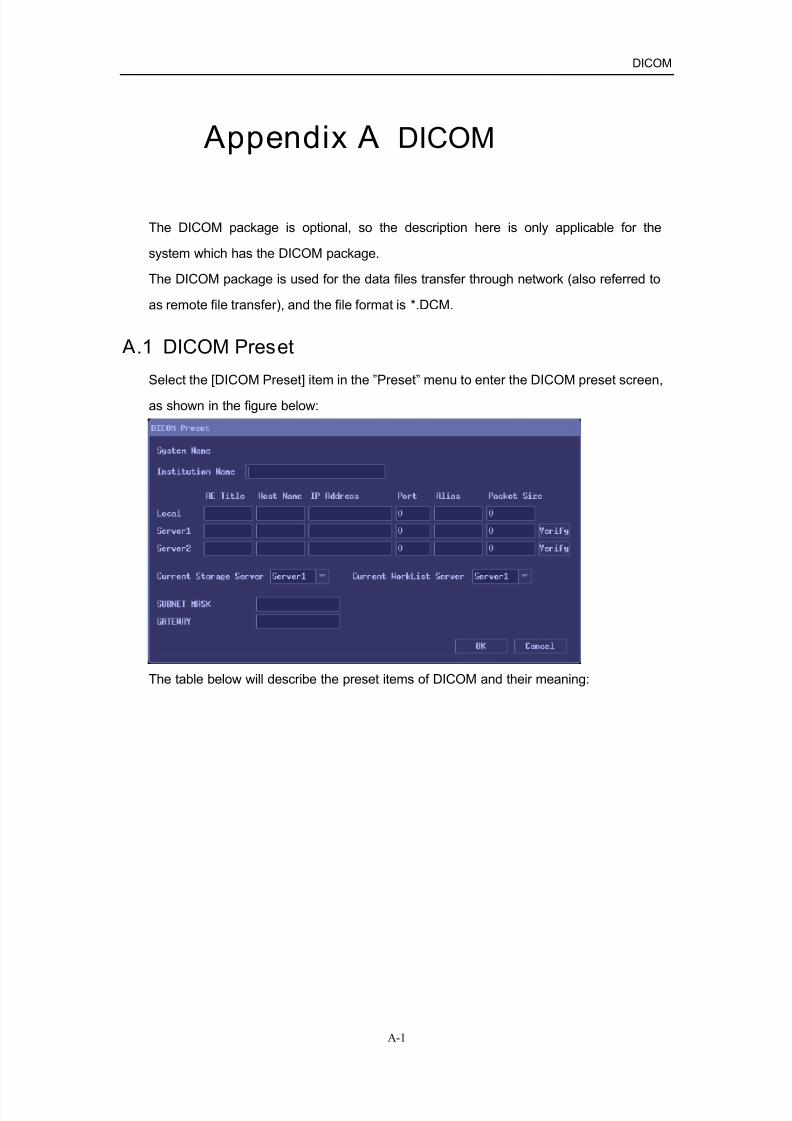
7/16/2019 DC-6 Operation Manual Basic CE V1.1
http://slidepdf.com/reader/full/dc-6-operation-manual-basic-ce-v11 146/149
DICOM
A-1
Appendix A DICOM
The DICOM package is optional, so the description here is only applicable for the
system which has the DICOM package.
The DICOM package is used for the data files transfer through network (also referred to
as remote file transfer), and the file format is *.DCM.
A.1 DICOM Preset
Select the [DICOM Preset] item in the ”Preset” menu to enter the DICOM preset screen,
as shown in the figure below:
The table below will describe the preset items of DICOM and their meaning:

7/16/2019 DC-6 Operation Manual Basic CE V1.1
http://slidepdf.com/reader/full/dc-6-operation-manual-basic-ce-v11 147/149
DICOM
A-2
No. Item name Meaning
1 System AE Title The name that has been set in the AE Title field of “Local” preset
column is displayed.
2 Institution Name Set the hospital name.
(1) AE Title Set the AE title of the local system. This name
is the same as that set in the System AE Title
field.
(2) Host Name Set the host name of the local system.
(3) IP Address Set the IP address of the local system.
(4) Port Set the port number of the local system.
(5) Alias Set the alias of the local system.
3 Local
(6) Packet Size Maximum PDU transmission size in bytes (does
not need to be changed).This setting can be changed in the range from
4K to 64K. If a value more than 64K is
entered, a value of 16K is set.
4 Server1/Server2 (1) AE Title Set the AE title of the remote system.
(2) Host Name Set the host name of the remote system.
(3) IP Address Set the IP address of the remote system.
(4) Port Set the port number of the remote system.
(5) Alias Set the alias of Server1/Server2.
(6) Packet Size Maximum PDU reception size in bytes (does
not need to be changed).
This setting can be changed in the range from
4K to 64 K. If a value less than 4K or more
than 64K is entered, a value of 16K is set.
5 Verify After set the information of Server, click this button to verify the
server is connected or not.
6 Current Save
Server
Select the current save server.
7 Current Worklist
Server
Select the worklist server.
8 Subnet Mask
Code
Set the subnet mask.
9 Gateway Set the gateway.
10 OK When this button is clicked, the changed parameters are saved
and the window is closed.
11 Cancel When this button is clicked, the window is closed without saving
the changed parameters.

7/16/2019 DC-6 Operation Manual Basic CE V1.1
http://slidepdf.com/reader/full/dc-6-operation-manual-basic-ce-v11 148/149
DICOM
A-3
A.2 DICOM Operation
If the system is installed with the DICOM package, you can perform the operations as
follows:
1. Press the 『Freeze』 key to freeze the image.
2. Press the『Menu』key to open the freeze menu, Move the cursor onto the [DICOM]
item and open its submenu.
Send IMG
Function: You can send the current scanning images to the DICOM server.
1. Move the cursor onto the [Send IMG] item and click the『Set』key.
2. The prompt message is displayed as “Sending data…” at the bottom of the
screen. And the screen will display the message of successful sending after the
sending is complete.
Send Cine
Function: to send the currently-scanning cine images to the server.
1. Move the cursor onto [Send Cine], and press the『Set』key, and then the images
are to be send.
2. After the sending is complete, the screen will display the message showing that
the sending is successful.
Send File
Function: to send the local DCM files to the DICOM server.
1. Move the cursor onto [Send File], and press the『Set』key. The “Open File” dialog
box appears on the screen. After the desired file is selected, sending starts.
2. After the sending is complete, the screen will display the message showing that
the sending is successful.

7/16/2019 DC-6 Operation Manual Basic CE V1.1
http://slidepdf.com/reader/full/dc-6-operation-manual-basic-ce-v11 149/149