dc machines and transformersamcresearch.weebly.com/uploads/9/7/6/6/97668312/chapter_1.pdfelectric...
TRANSCRIPT

Course Instructor: Amjad [email protected]
Department of Electrical Engineering, CECOS University of IT and Emerging Sciences, Peshawar, Pakistan
1
DC Machines and TransformersCourse Credit Hours: 2+1Lecture Timings: Friday @ 13:50 to 15:30 Lecture Venue: Communication Systems Lab

By: Amjad Iqbal Chapter 1: Introduction to Machinery Principles
Recommended Readings
Textbook:
Electric Machinery Fundaments 4th Edition by Stephen Chapman
Other Books:
A Textbook of Electrical Technology by B.L Theraja
Electric Machinery by A. E. Fitzgerald, McGraw-Hill , 6th edition
2
By: Amjad Iqbal Chapter 1: Introduction to Machinery Principles
Grading Policy
Quizzes= 12.5 %
Assignments= 12.5%
Mid Term= 25%
Final Term= 50 %
3

By: Amjad Iqbal Chapter 1: Introduction to Machinery Principles
Brief Introduction about me
MS in Electrical Engineering, CECOS University of IT and Emerging Sciences, Peshawar, Pakistan (2016-2018).
BS in Electrical Engineering, COMSATS Institute of Information Technology, Islamabad, Pakistan (2012-2016).
Specialization in Antennas and Microwave Filters.
Teaching Experience in CECOS University (2016-Till date).
Email: [email protected]
Course material can be access from: www.amcresearch.weebly.com
4
Introduction to Machinery Principles
Amjad [email protected]
Department of Electrical Engineering, CECOS University of IT and Emerging Sciences, Peshawar, Pakistan
5
Chapter 1

By: Amjad Iqbal Chapter 1: Introduction to Machinery Principles
Summary
1. Basic concept of electrical machines fundamentals• Rotational component measurements
• Angular Velocity, Acceleration
• Torque, Work, Power
• Newton’s Law of Rotation
• Magnetic Field study
• Production of a Magnetic Field
• Magnetic Circuits
6

By: Amjad Iqbal Chapter 1: Introduction to Machinery Principles
Summary
2. Magnetic Behavior of Ferromagnetic Materials
3. How magnetic field can affect its surroundings:
• Faraday’s Law – Induced Voltage from a Time-Changing Magnetic Field.
• Production of Induced Force on a Wire.
• Induced Voltage on a Conductor moving in a Magnetic Field
4. Linear DC Machines 7

By: Amjad Iqbal Chapter 1: Introduction to Machinery Principles
Introduction
An Electrical Machine is a device that can convert either mechanical energy to electrical energy or electrical energy to mechanical energy
An Electrical Machine may be Motor or Generator
Mechanical energy Electric energy : GENERATOR
Electric energy mechanical energy : MOTOR
8

By: Amjad Iqbal Chapter 1: Introduction to Machinery Principles
Introduction
Almost all practical motors and generators convert energy from one form to another through the action of a magnetic field.
Only machines using magnetic fields to perform such conversions will be considered in this course.
When we talk about machines, another related device is thetransformer. A transformer is a device that converts ac electricenergy at one voltage level to ac electric energy at anothervoltage level.
9
By: Amjad Iqbal Chapter 1: Introduction to Machinery Principles
Introduction
Transformers are usually studied together with generators and motors because they operate on the same principle, the difference is just in the action of a magnetic field to accomplish the change in voltage level.
10

By: Amjad Iqbal Chapter 1: Introduction to Machinery Principles
Why are electric motors and generators so common?
Electric power is a clean and efficient energy source that is very easy to transmit over long distances and easy to control.
Does not require constant ventilation and fuel (compare to internal-combustion engine), free from pollutant associated with combustion
11
By: Amjad Iqbal Chapter 1: Introduction to Machinery Principles
Basic concept of electrical machines fundamentals
Almost all electric machines rotate about an axis, called the shaft of the machines. It is important to have a basic understanding of rotational motion.
12

By: Amjad Iqbal Chapter 1: Introduction to Machinery Principles
Angular position, Ɵ
is the angle at which it is oriented, measured from some arbitrary reference point.
Its measurement units are in radians (rad) or in degrees. It is similar to the linear concept of distance along a line.
• Conventional notation:
• +ve value for anticlockwise rotation • -ve value for clockwise rotation
13

By: Amjad Iqbal Chapter 1: Introduction to Machinery Principles
Angular Velocity, ω
Linear velocity along a line is defined as the “ Rate of change of displacement along the line (r) with respect to time and is given as:
𝑣 =𝑑𝑟
𝑑𝑡(m/sec)
where: r – distance traverse by the body
t – time taken to travel the distance r
14

By: Amjad Iqbal Chapter 1: Introduction to Machinery Principles
Angular Velocity, ω
Angular velocity is defined as the “ Rate of change of angular displacement with respect to time and is given as:
ω=𝑑𝜃
𝑑𝑡(rad/sec)
where: Ɵ- Angular position/ angular distance traversed by the rotating body
t – time taken for the rotating body to traverse the specified distance, Ɵ .
15

By: Amjad Iqbal Chapter 1: Introduction to Machinery Principles
Angular Velocity, ω
Other Units of Angular Velocity are:
Revolutions per second Revolutions per minute
Different symbols for speed when it is expressed in different units
𝜔𝑚= angular velocity expressed in radians per second 𝑓𝑚= angular velocity expressed in revolutions per second 𝑛𝑚= angular velocity expressed in revolutions per minute
16

By: Amjad Iqbal Chapter 1: Introduction to Machinery Principles
Angular Velocity, ω
The subscript m on these symbols indicates mechanical quantity, opposed to electrical quantity.
𝑛𝑚 = 60𝑓𝑚
𝑓𝑚 =𝜔𝑚
2𝜋
17
By: Amjad Iqbal Chapter 1: Introduction to Machinery Principles
Angular acceleration, α
is defined as the rate of change in angular velocity with respect to time. Its formulation is as shown:
𝛼 =𝑑𝜔
𝑑𝑡(𝑟𝑎𝑑/𝑠𝑒𝑐2)
Where
𝑑𝜔= Change in angular velocity
𝑑𝑡= Change in time
18

By: Amjad Iqbal Chapter 1: Introduction to Machinery Principles
Torque, 𝝉
In linear motion, a force applied to an object causes its velocity to change.
In the absence of a net force on the object, its velocity is constant.
The greater the force applied to the object, the more rapidly its velocity changes.
19
By: Amjad Iqbal Chapter 1: Introduction to Machinery Principles
Torque, 𝝉
Similarly in the concept of rotation, when an object is rotating, its angular velocity is constant unless a torque is present on it.
Greater the torque, more rapid the angular velocity changes.
• Torque is known as a rotational force applied to a rotating body giving angular acceleration. May be called as ‘twisting force’.
20

By: Amjad Iqbal Chapter 1: Introduction to Machinery Principles
Torque, 𝝉
Product of force applied to the object and the smallest distance between the line of action of the force and the object’s axis of rotation
𝜏 = (𝑓𝑜𝑟𝑐𝑒 𝑎𝑝𝑝𝑙𝑖𝑒𝑑)(𝑃𝑒𝑟𝑝𝑒𝑛𝑑𝑖𝑐𝑢𝑙𝑎𝑟 𝐷𝑖𝑠𝑡𝑎𝑛𝑐𝑒)
𝜏 = (𝐹)(𝑟𝑆𝑖𝑛𝜃)
𝜏 = 𝑟𝐹𝑆𝑖𝑛𝜃
It is vector Quantity
Unit is Newton-meter (N-m)
21

By: Amjad Iqbal Chapter 1: Introduction to Machinery Principles
Torque, 𝝉
22
By: Amjad Iqbal Chapter 1: Introduction to Machinery Principles
Work, W
is defined as the application of Force through a distance. Therefore, work may be defined as:
𝑊 = 𝐹𝑑𝑟
Assuming that the direction of F is collinear (in the same direction) with the direction of motion and constant in magnitude, hence,
𝑊 = 𝐹𝑟
23

By: Amjad Iqbal Chapter 1: Introduction to Machinery Principles
Work, W
Applying the same concept for rotating bodies,
𝑊 = 𝜏𝑑𝜃
Assuming that 𝜏 is constant,
𝑊 = 𝜏𝜃 (𝐽𝑜𝑢𝑙𝑒𝑠)
24

By: Amjad Iqbal Chapter 1: Introduction to Machinery Principles
Power, P
is defined as rate of doing work. Hence,
𝑃 =𝑑𝑊
𝑑𝑡𝑤𝑎𝑡𝑡𝑠 =
𝑑
𝑑𝑡𝐹𝑟 = 𝐹
𝑑𝑟
𝑑𝑡= 𝐹𝑣
Applying this for rotating bodies, ,
𝑃 =𝑑
𝑑𝑡(𝜏𝜃)
𝑃 = 𝜏𝑑𝜃
𝑑𝑡= 𝜏𝜔
This equation can describe the mechanical power on the shaft of a motor or generator.
25

By: Amjad Iqbal Chapter 1: Introduction to Machinery Principles
Power, P
𝑃 = 𝜏𝜔 Its is the correct relationship between power, torque and speed if
power is measured in watts, torque in newton-meter and speed in radians per second.
In US Engineering, Torque is measured in pound-feet, speed in revolution per minute and power in either watts or horse power.
A constant must be introduced for unit conversion factor.
𝑃 𝑤𝑎𝑡𝑡𝑠 =𝜏 𝑙𝑏 − 𝑓𝑡 𝑛(𝑟𝑝𝑚)
7.04
𝑃(ℎ𝑜𝑟𝑠𝑒𝑝𝑜𝑤𝑒𝑟) =𝜏 𝑙𝑏 − 𝑓𝑡 𝑛(𝑟𝑝𝑚)
5252
26

By: Amjad Iqbal Chapter 1: Introduction to Machinery Principles
Newton’s Law of Rotation
Newton’s law for objects moving in a straight line gives a relationship between the force applied to the object and the acceleration experience by the object as the result of force applied to it. In general,
𝐹 = 𝑚𝑎Where:
F – Force applied m – mass of object a – resultant acceleration of object
27
By: Amjad Iqbal Chapter 1: Introduction to Machinery Principles
Newton’s Law of Rotation
Applying these concept for rotating bodies,
𝜏 = 𝐽𝛼 (𝑁𝑚)
Where:
𝜏 - Torque
J – moment of inertia
𝛼 - angular acceleration
28
By: Amjad Iqbal Chapter 1: Introduction to Machinery Principles
The Magnetic Field
Magnetic fields are the fundamental mechanism by which energy is converted from one form to another in motors, generators and transformers.
First, we are going to look at the basic principle – A current-carrying wire produces a magnetic field in the area around it.
29

By: Amjad Iqbal Chapter 1: Introduction to Machinery Principles
The Magnetic Field
• A time changing magnetic field induces a voltage in a coil of wire if it passes through that coil. (This is the basis of transformer action)
• A current carrying wire in the presence of magnetic field has force induced on it. (This is the basis of motor action)
• A moving wire in the presence of magnetic field has a voltage induced in it. (This is the basis of Generator action)
30

By: Amjad Iqbal Chapter 1: Introduction to Machinery Principles
Ampere’s Law
the basic law governing the production of a magnetic field by a current:
𝐻𝑑𝑙 = 𝐼𝑛𝑒𝑡
where H is the magnetic field intensity produced by the current 𝐼𝑛𝑒𝑡 and dl is a differential element of length along the path of integration. H is measured in Ampere-turns per meter.
31

By: Amjad Iqbal Chapter 1: Introduction to Machinery Principles
Ampere’s Law
• Consider a current currying conductor is wrapped around a ferromagnetic core.
• Applying Ampere’s law, the total amount of magnetic field induced will be proportional to the amount of current flowing through the conductor wound with N turns around the ferromagnetic material as shown. Since the core is made of ferromagnetic material, it is assume that a majority of the magnetic field will be confined to the core.
32
By: Amjad Iqbal Chapter 1: Introduction to Machinery Principles
Ampere’s Law
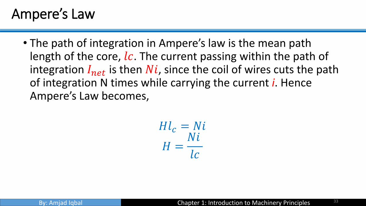
• The path of integration in Ampere’s law is the mean path length of the core, 𝑙𝑐. The current passing within the path of integration 𝐼𝑛𝑒𝑡 is then 𝑁𝑖, since the coil of wires cuts the path of integration N times while carrying the current i. Hence Ampere’s Law becomes,
𝐻𝑙𝑐 = 𝑁𝑖
𝐻 =𝑁𝑖
𝑙𝑐
33

By: Amjad Iqbal Chapter 1: Introduction to Machinery Principles
Ampere’s Law
• In this sense, H (Ampere turns per metre) is known as the effort required to induce a magnetic field. The strength of the magnetic field flux produced in the core also depends on the material of the core. Thus,
𝐵 = 𝜇𝐻
• B = magnetic flux density (webers per square meter, Tesla (T))
• μ= magnetic permeability of material (Henrys per meter)
• H = magnetic field intensity (ampere-turns per meter)
34

By: Amjad Iqbal Chapter 1: Introduction to Machinery Principles
Ampere’s Law
• The constant 𝜇 may be further expanded to include relative permeability which can be defined as below:
𝜇𝑟 =𝜇
𝜇0• 𝜇𝑜 = permeability of free space
• Hence the permeability value is a combination of the relativepermeability and the permeability of free space. The value ofrelative permeability is dependent upon the type of material used.The higher the amount permeability, the higher the amount of fluxinduced in the core. Relative permeability is a convenient way tocompare the magnetizability of materials.
35

By: Amjad Iqbal Chapter 1: Introduction to Machinery Principles
Ampere’s Law
• Also, because the permeability of iron is so much higher than that of air, the majority of the flux in an iron core remains inside the core instead of travelling through the surrounding air, which has lower permeability. The small leakage flux that does leave the iron core is important in determining the flux linkages between coils and the self-inductances of coils in transformers and motors.
• In a core such as in the figure
𝐵 = 𝜇𝐻 =𝜇𝑁𝑖𝑙𝑐
36

By: Amjad Iqbal Chapter 1: Introduction to Machinery Principles
Ampere’s Law
• Now, to measure the total flux flowing in the ferromagnetic core, consideration has to be made in terms of its cross sectional area (CSA). Therefore
• In a core such as in the figure
∅ = 𝐵 𝑑𝐴
Where: A – cross sectional area throughout the core
37

By: Amjad Iqbal Chapter 1: Introduction to Machinery Principles
Ampere’s Law
• Assuming that the flux density in the ferromagnetic core is constant throughout hence constant A, the equation simplifies to be:
∅ = 𝐵𝐴
Taking into account past derivation of B
∅ =𝜇𝑁𝑖𝐴
𝑙𝑐
38

By: Amjad Iqbal Chapter 1: Introduction to Machinery Principles
Magnetics Circuits
• The flow of magnetic flux induced in the ferromagnetic core can be made analogous to an electrical circuit hence the name magnetic circuit.
39
By: Amjad Iqbal Chapter 1: Introduction to Machinery Principles
Magnetics Circuits
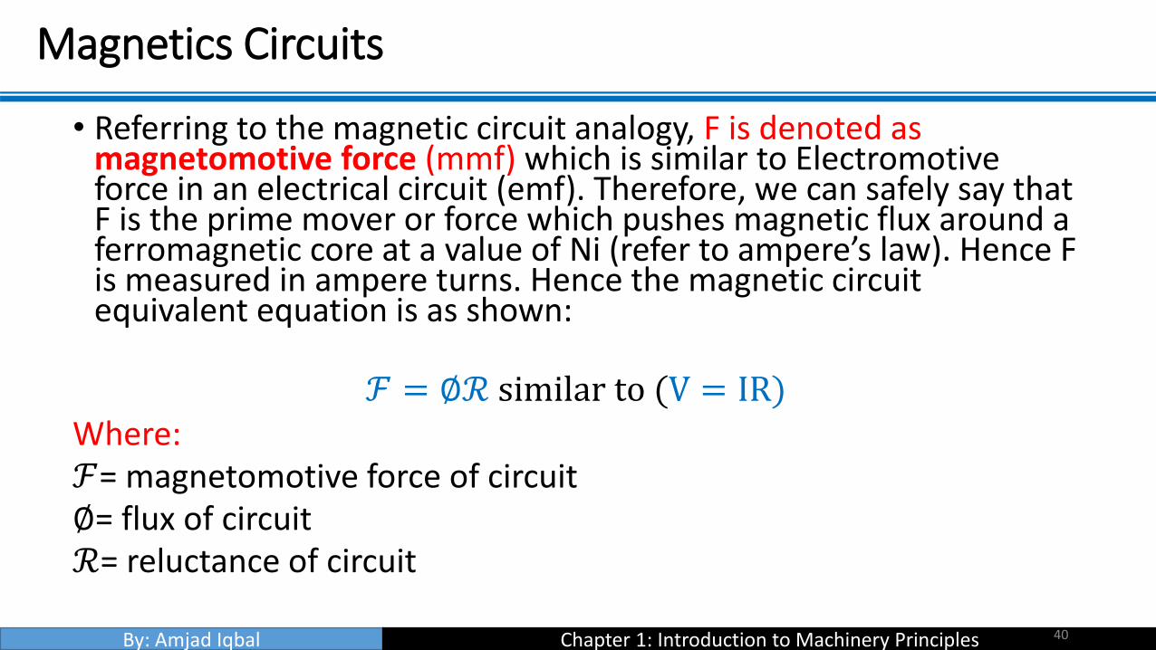
• Referring to the magnetic circuit analogy, F is denoted as magnetomotive force (mmf) which is similar to Electromotive force in an electrical circuit (emf). Therefore, we can safely say that F is the prime mover or force which pushes magnetic flux around a ferromagnetic core at a value of Ni (refer to ampere’s law). Hence F is measured in ampere turns. Hence the magnetic circuit equivalent equation is as shown:
ℱ = ∅ℛ similar to (V = IR)Where:ℱ= magnetomotive force of circuit∅= flux of circuitℛ= reluctance of circuit
40

By: Amjad Iqbal Chapter 1: Introduction to Machinery Principles
Magnetics Circuits
• The polarity of the mmf will determine the direction of flux. To easily determine the direction of flux, the ‘right hand curl’ rule is utilized:
a) The direction of the curled fingers determines the current flow.
b) The resulting thumb direction will show the magnetic flux flow.
• The element of R in the magnetic circuit analogy is similar in concept to the electrical resistance. It is basically the measure of material resistance to the flow of magnetic flux.
• Reluctance in this analogy obeys the rule of electrical resistance (Series and Parallel Rules).
• Reluctance is measured in Ampere-turns per weber.
41

By: Amjad Iqbal Chapter 1: Introduction to Machinery Principles
Magnetics Circuits
• Series Reluctance
ℛ𝑒𝑞 = ℛ1 +ℛ2 +ℛ3+………
• Parallel Reluctance,
1
ℛ𝑒𝑞=
1
ℛ1+1
ℛ2+1
ℛ3+…………
42

By: Amjad Iqbal Chapter 1: Introduction to Machinery Principles
Magnetics Circuits
• The inverse of electrical resistance is conductance which is a measure of conductivity of a material. Hence the inverse of reluctance is known as permeance, P where it represents the degree at which the material permits the flow of magnetic flux.
43
By: Amjad Iqbal Chapter 1: Introduction to Machinery Principles
Magnetics Circuits
• By using the magnetic circuit approach, it simplifies calculations related to the magnetic field in a ferromagnetic material, however, this approach has inaccuracy embedded into it due to assumptions made in creating this approach (within 5% of the real answer). Possible reason of inaccuracy is due to:
• The magnetic circuit assumes that all flux are confined within the core, but in reality a small fraction of the flux escapes from the core into the surrounding low-permeability air, and this flux is called leakage flux.
44

By: Amjad Iqbal Chapter 1: Introduction to Machinery Principles
Magnetics Circuits
• The reluctance calculation assumes a certain mean path length and cross sectional area (csa) of the core. This is alright if the core is just one block of ferromagnetic material with no corners, for practical ferromagnetic cores which have corners due to its design, this assumption is not accurate.
• In ferromagnetic materials, the permeability varies with the amount of flux already in the material. The material permeability is not constant hence there is an existence of non-linearity of permeability.
45

By: Amjad Iqbal Chapter 1: Introduction to Machinery Principles
Magnetics Circuits
• For ferromagnetic core which has air gaps, there are fringing effects that should be taken into account as shown:
46
By: Amjad Iqbal Chapter 1: Introduction to Machinery Principles
Example 1-1
47
By: Amjad Iqbal Chapter 1: Introduction to Machinery Principles
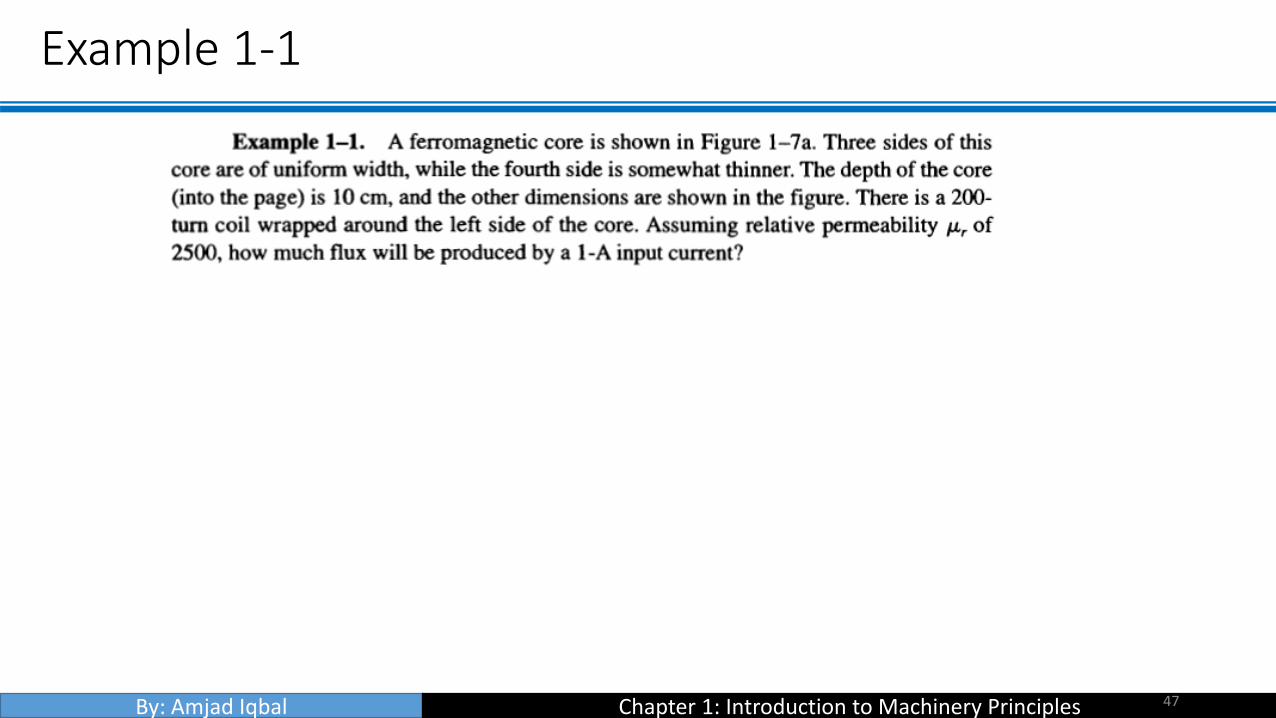
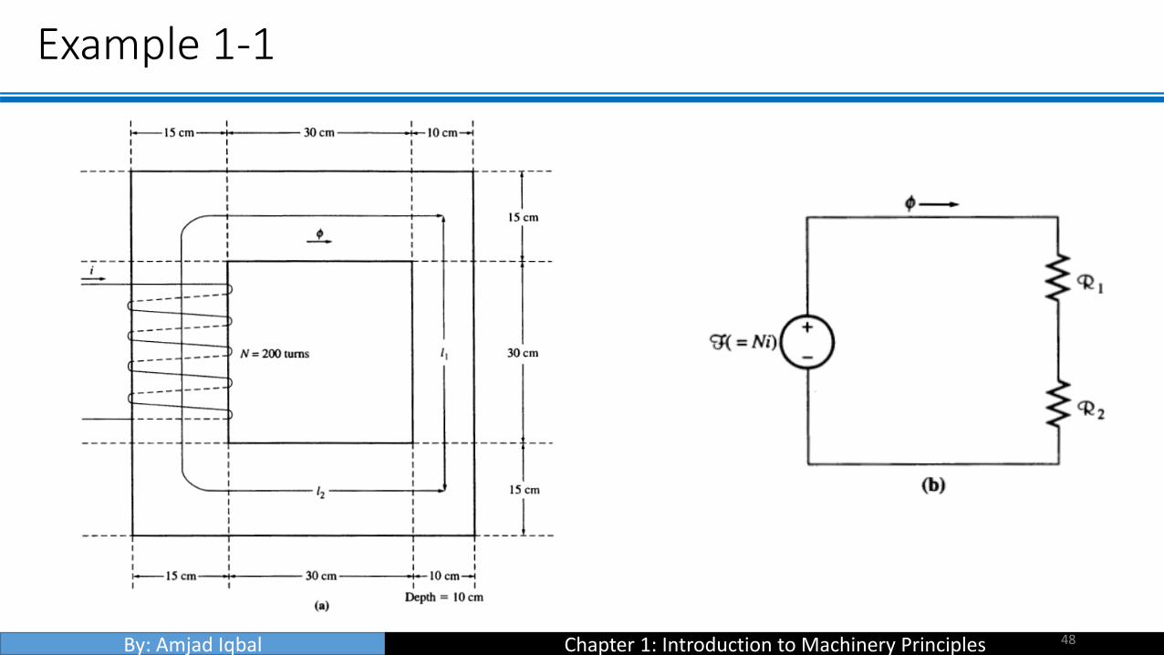
Example 1-1
48

By: Amjad Iqbal Chapter 1: Introduction to Machinery Principles
Example 1-1
49

By: Amjad Iqbal Chapter 1: Introduction to Machinery Principles
Example 1-1
50

By: Amjad Iqbal Chapter 1: Introduction to Machinery Principles
Example 1-2
51
By: Amjad Iqbal Chapter 1: Introduction to Machinery Principles
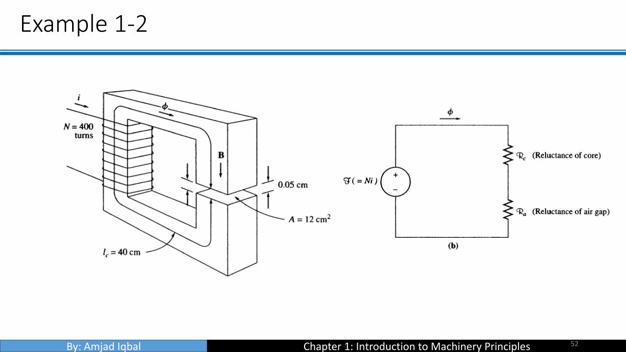
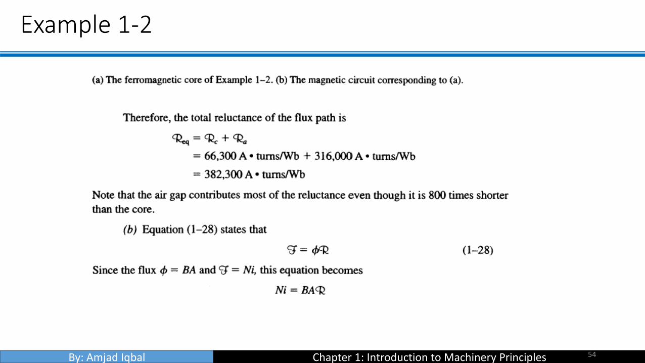
Example 1-2
52

By: Amjad Iqbal Chapter 1: Introduction to Machinery Principles
Example 1-2
53
By: Amjad Iqbal Chapter 1: Introduction to Machinery Principles
Example 1-2
54

By: Amjad Iqbal Chapter 1: Introduction to Machinery Principles
Example 1-2
55

By: Amjad Iqbal Chapter 1: Introduction to Machinery Principles
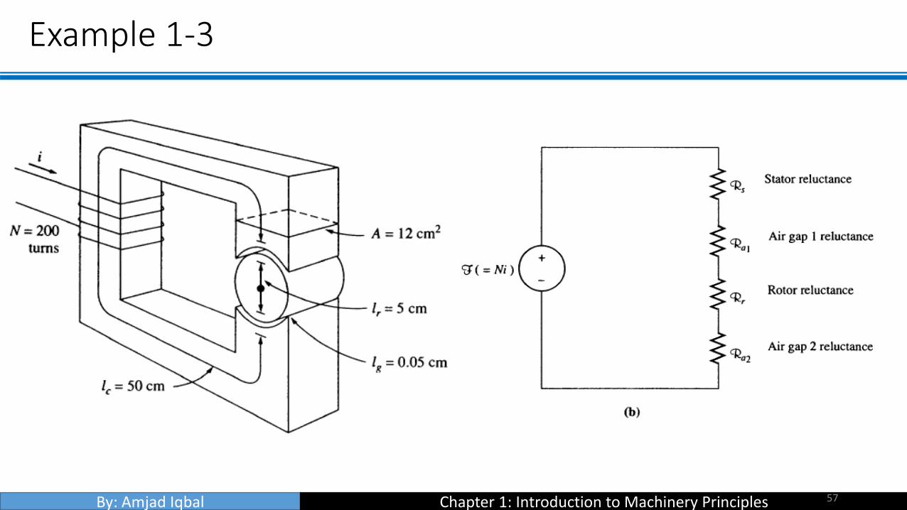
Example 1-3
56
By: Amjad Iqbal Chapter 1: Introduction to Machinery Principles
Example 1-3
57

By: Amjad Iqbal Chapter 1: Introduction to Machinery Principles
Example 1-3
58

By: Amjad Iqbal Chapter 1: Introduction to Machinery Principles
Example 1-3
59

By: Amjad Iqbal Chapter 1: Introduction to Machinery Principles
Example 1-3
60

By: Amjad Iqbal Chapter 1: Introduction to Machinery Principles
Magnetic Behavior of Ferromagnetic Materials
• Materials which are classified as non-magnetic all show a linear relationship between the flux density B and coil current I. In other words, they have constant permeability. Thus, for example, in free space, the permeability is constant. But in iron and other ferromagnetic materials it is not constant.
• For magnetic materials, a much larger value of B is produced in these materials than in free space. Therefore, the permeability of magnetic materials is much higher than μo. However, the permeability is not linear anymore but does depend on the current over a wide range.
61
By: Amjad Iqbal Chapter 1: Introduction to Machinery Principles
Magnetic Behavior of Ferromagnetic Materials
• Thus, the permeability is the property of a medium that determines its magnetic characteristics. In other words, the concept of magnetic permeability corresponds to the ability of the material to permit the flow of magnetic flux through it.
• In electrical machines and electromechanical devices a somewhat linear relationship between B and I is desired, which is normally approached by limiting the current.
62

By: Amjad Iqbal Chapter 1: Introduction to Machinery Principles
Magnetic Behavior of Ferromagnetic Materials
• When the flux produced in the core is plotted versus the mmfproducing it, the resulting plot looks like this (a). This plot is called a saturation curve or a magnetization curve. A small increase in the mmf produces a huge increase in the resulting flux. After a certain point, further increases in the mmf produce relatively smaller increases in the flux. Finally, there will be no change at all as you increase mmf further. The region in which the curve flattens out is called saturation region, and the core is said to be saturated. The region where the flux changes rapidly is called the unsaturated region. The transition region is called the ‘knee’ of the curve.
63

By: Amjad Iqbal Chapter 1: Introduction to Machinery Principles
Magnetic Behavior of Ferromagnetic Materials
64

By: Amjad Iqbal Chapter 1: Introduction to Machinery Principles
Magnetic Behavior of Ferromagnetic Materials
65
• From equation H = Ni/lc = F/lc and ∅=BA, it can be seen that
magnetizing intensity is directly proportional to mmf and magnetic flux
density is directly proportional to flux for any given core. B=μH
slope of curve is the permeability of the core at that magnetizing
intensity. The curve (b) shows that the permeability is large and
relatively constant in the unsaturated region and then gradually drops to
a low value as the core become heavily saturated.

By: Amjad Iqbal Chapter 1: Introduction to Machinery Principles
Magnetic Behavior of Ferromagnetic Materials
• Advantage of using a ferromagnetic material for cores in electric machines and transformers is that one gets more flux for a given mmf than with air (free space).
• If the resulting flux has to be proportional to the mmf, then the core must be operated in the unsaturated region.
• Generators and motors depend on magnetic flux to produce voltage and torque, so they need as much flux as possible. So, they operate near the knee of the magnetization curve (flux not linearly related to the mmf). This non-linearity as a result gives peculiar behaviours to machines.
• As magnetizing intensity H increased, the relative permeability first increases and then starts to drop off.
66
By: Amjad Iqbal Chapter 1: Introduction to Machinery Principles
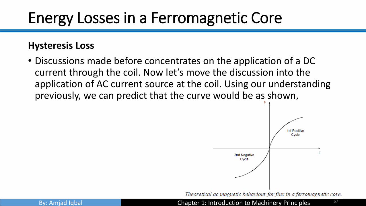
Energy Losses in a Ferromagnetic Core
Hysteresis Loss
• Discussions made before concentrates on the application of a DC current through the coil. Now let’s move the discussion into the application of AC current source at the coil. Using our understanding previously, we can predict that the curve would be as shown,
67

By: Amjad Iqbal Chapter 1: Introduction to Machinery Principles
Energy Losses in a Ferromagnetic Core
Hysteresis Loss
• Unfortunately, the above assumption is only correct provided that the core is ‘perfect’ i.e. there are no residual flux present during the negative cycle of the ac current flow. A typical flux behaviour (or known as hysteresis loop) in a ferromagnetic core is as shown in the next page.
68

By: Amjad Iqbal Chapter 1: Introduction to Machinery Principles
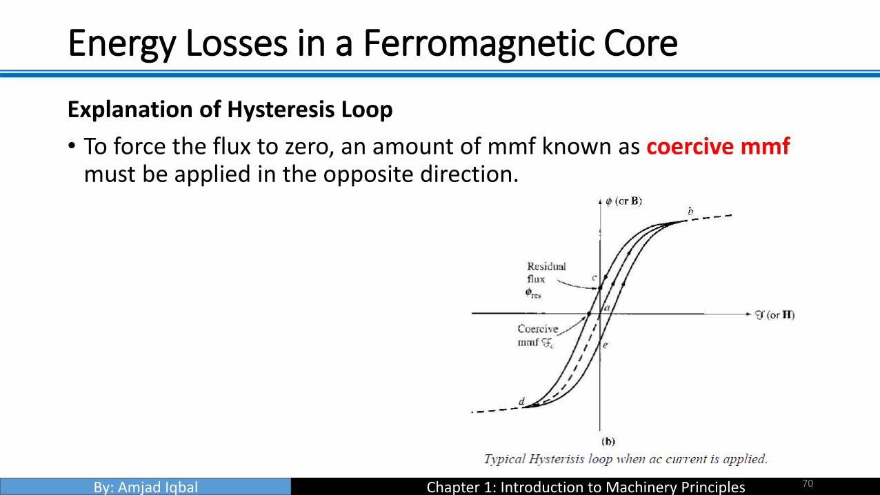
Energy Losses in a Ferromagnetic Core
Explanation of Hysteresis Loop
• Apply AC current. Assume flux in the core is initially zero.
• As current increases, the flux traces the path ab. (saturation curve)
• When the current decreases, the flux traces out a different path from the one when the current increases.
• When current decreases, the flux traces out path bcd.
• When the current increases again, it traces out path deb.
69
By: Amjad Iqbal Chapter 1: Introduction to Machinery Principles
Energy Losses in a Ferromagnetic Core
Explanation of Hysteresis Loop
• To force the flux to zero, an amount of mmf known as coercive mmfmust be applied in the opposite direction.
70

By: Amjad Iqbal Chapter 1: Introduction to Machinery Principles
Energy Losses in a Ferromagnetic Core
Why does hysteresis occur?
• To understand hysteresis in a ferromagnetic core, we have to look into the behaviour of its atomic structure before, during and after the presence of a magnetic field.
• The atoms of iron and similar metals (cobalt, nickel, and some of their alloys) tend to have their magnetic fields closely aligned with each other. Within the metal, there is an existence of small regions known as domains where in each domain there is a presence of a small magnetic field which randomly aligned through the metal structure.
71

By: Amjad Iqbal Chapter 1: Introduction to Machinery Principles
Energy Losses in a Ferromagnetic Core
Why does hysteresis occur?
• Magnetic field direction in each domain is random as such that the net magnetic field is zero.
• When mmf is applied to the core, each magnetic field will align with respect to the direction of the magnetic field. That explains the exponential increase of magnetic flux during the early stage of magnetisation. As more and more domain are aligned to the magnetic field, the total magnetic flux will maintain at a constant level hence as shown in the magnetisation curve (saturation).
72

By: Amjad Iqbal Chapter 1: Introduction to Machinery Principles
Energy Losses in a Ferromagnetic Core
Why does hysteresis occur?
• When mmf is removed, the magnetic field in each domain will try to revert to its random state.
• However, not all magnetic field domain’s would revert to its random state hence it remained in its previous magnetic field position. This is due to the lack of energy required to disturb the magnetic field alignment.
• Hence the material will retain some of its magnetic properties (permanent magnet) up until an external energy is applied to the material. Examples of external energy may be in the form of heat or large mechanical shock. That is why a permanent magnet can lose its magnetism if it is dropped, hit with a hammer or heated.
73

By: Amjad Iqbal Chapter 1: Introduction to Machinery Principles
Energy Losses in a Ferromagnetic Core
Why does hysteresis occur?
• Therefore, in an ac current situation, to realign the magnetic field in each domain during the opposite cycle would require extra mmf (also known as coercive mmf).
• This extra energy requirement is known as hysteresis loss.
• The larger the material, the more energy is required hence the higher the hysteresis loss.
• Area enclosed in the hysteresis loop formed by applying an ac current to the core is directly proportional to the energy lost in a given ac cycle.
74

By: Amjad Iqbal Chapter 1: Introduction to Machinery Principles
Energy Losses in a Ferromagnetic Core
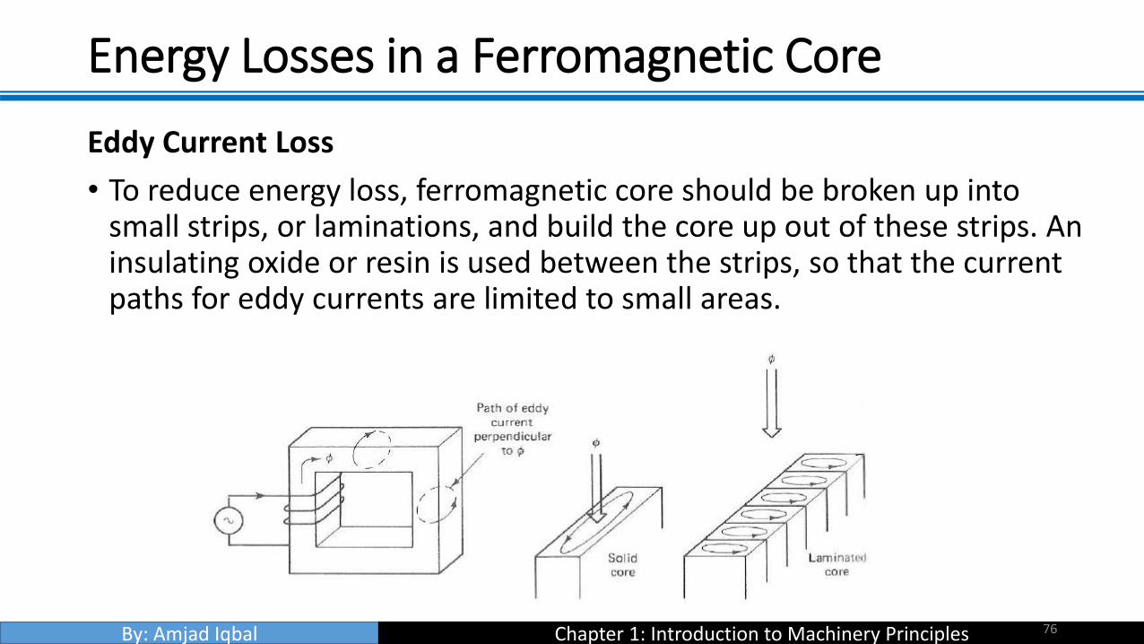
Eddy Current Loss • A time-changing flux induces voltage within a ferromagnetic core.
• These voltages cause swirls of current to flow within the core – eddy currents.
• Energy is dissipated (in the form of heat) because these eddy currents are flowing in a resistive material (iron)
• The amount of energy lost to eddy currents is proportional to the size of the paths they follow within the core.
75
By: Amjad Iqbal Chapter 1: Introduction to Machinery Principles
Energy Losses in a Ferromagnetic Core
Eddy Current Loss
• To reduce energy loss, ferromagnetic core should be broken up into small strips, or laminations, and build the core up out of these strips. An insulating oxide or resin is used between the strips, so that the current paths for eddy currents are limited to small areas.
76

By: Amjad Iqbal Chapter 1: Introduction to Machinery Principles
FARADAY’S LAW
• ‘If a flux passes through a turn of a coil of wire, voltage will be induced in the turn of the wire that is directly proportional to the rate of change in the flux with respect of time’
• If there is N number of turns in the coil with the same amount of flux flowing through it, hence:
where: N – number of turns of wire in coil.
Note the negative sign at the equation above which is in accordance to Lenz’ Law
77

By: Amjad Iqbal Chapter 1: Introduction to Machinery Principles
FARADAY’S LAW
• Lenz’ Law States ‘The direction of the build-up voltage in the coil is as such that if the coils were short circuited, it would produce current that would cause a flux opposing the original flux change.’
•
78

By: Amjad Iqbal Chapter 1: Introduction to Machinery Principles
FARADAY’S LAW
• If the flux shown is increasing in strength, then the voltage built up in the coil will tend to establish a flux that will oppose the increase.
• A current flowing as shown in the figure would produce a flux opposing the increase.
• So, the voltage on the coil must be built up with the polarity required to drive the current through the external circuit. So, -eind
• NOTE: In Chapman, the minus sign is often left out because the polarity of the resulting voltage can be determined from physical considerations.
79

By: Amjad Iqbal Chapter 1: Introduction to Machinery Principles
FARADAY’S LAW
• Equation eind = -dφ/dt assumes that exactly the same flux is present in each turn of the coil. This is not true, since there is leakage flux. This equation will give valid answer if the windings are tightly coupled, so that the vast majority of the flux passing thru one turn of the coil does indeed pass through all of them.
• Now consider the induced voltage in the ith turn of the coil,
• Since there is N number of turns,
80

By: Amjad Iqbal Chapter 1: Introduction to Machinery Principles
FARADAY’S LAW
• The equation above may be rewritten into,
• where λ (flux linkage) is defined as:
81

By: Amjad Iqbal Chapter 1: Introduction to Machinery Principles
FARADAY’S LAW
• Faraday’s law is the fundamental property of magnetic fields involved in transformer operation.
• Lenz’s Law in transformers is used to predict the polarity of the voltages induced in transformer windings.
82

By: Amjad Iqbal Chapter 1: Introduction to Machinery Principles
Production of Induced Force on a Wire
• A current carrying conductor present in a uniform magnetic field of flux density B, would produce a force to the conductor/wire. Dependent upon the direction of the surrounding magnetic field, the force induced is given by:
• where:
• i – represents the current flow in the conductor
• l – length of wire, with direction of l defined to be in the direction of current flow
• B – magnetic field density
83
By: Amjad Iqbal Chapter 1: Introduction to Machinery Principles
Production of Induced Force on a Wire
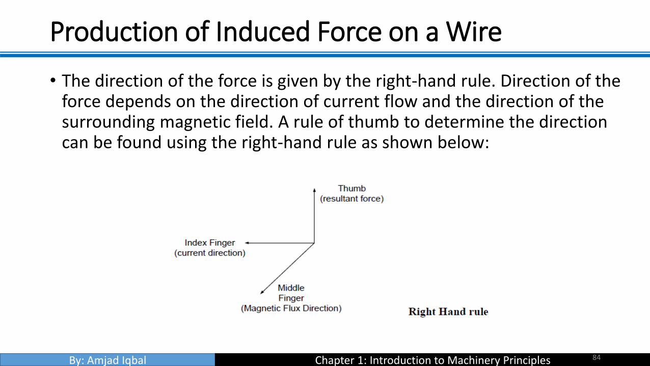
• The direction of the force is given by the right-hand rule. Direction of the force depends on the direction of current flow and the direction of the surrounding magnetic field. A rule of thumb to determine the direction can be found using the right-hand rule as shown below:
84

By: Amjad Iqbal Chapter 1: Introduction to Machinery Principles
Production of Induced Force on a Wire
• The induced force formula shown earlier is true if the current carrying conductor is perpendicular to the direction of the magnetic field. If the current carrying conductor is position at an angle to the magnetic field, the formula is modified to be as follows:
• Where: θ- angle between the conductor and the direction of the magnetic field.
• In summary, this phenomenon is the basis of an electric motor where torque or rotational force of the motor is the effect of the stator field current and the magnetic field of the rotor.
85
By: Amjad Iqbal Chapter 1: Introduction to Machinery Principles
Induced Voltage on a Conductor Moving in a Magnetic Field
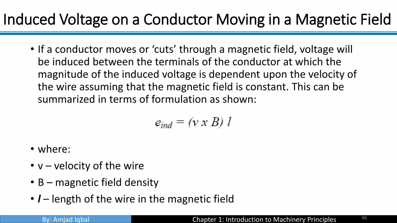
• If a conductor moves or ‘cuts’ through a magnetic field, voltage will be induced between the terminals of the conductor at which the magnitude of the induced voltage is dependent upon the velocity of the wire assuming that the magnetic field is constant. This can be summarized in terms of formulation as shown:
• where:
• v – velocity of the wire
• B – magnetic field density
• l – length of the wire in the magnetic field
86

By: Amjad Iqbal Chapter 1: Introduction to Machinery Principles
Induced Voltage on a Conductor Moving in a Magnetic Field
• Note: The value of l (length) is dependent upon the angle at which the wire cuts through the magnetic field. Hence a more complete formula will be as follows:
• where:
• Ɵ - angle between the conductor and the direction of (v x B)
• The induction of voltages in a wire moving in a magnetic field is fundamental to the operation of all types of generators.
87

By: Amjad Iqbal Chapter 1: Introduction to Machinery Principles
The Linear DC Machine
• Linear DC machine is the simplest form of DC machine which is easy to understand and it operates according to the same principles and exhibits the same behaviour as motors and generators. Consider the following:
88
By: Amjad Iqbal Chapter 1: Introduction to Machinery Principles
The Linear DC Machine
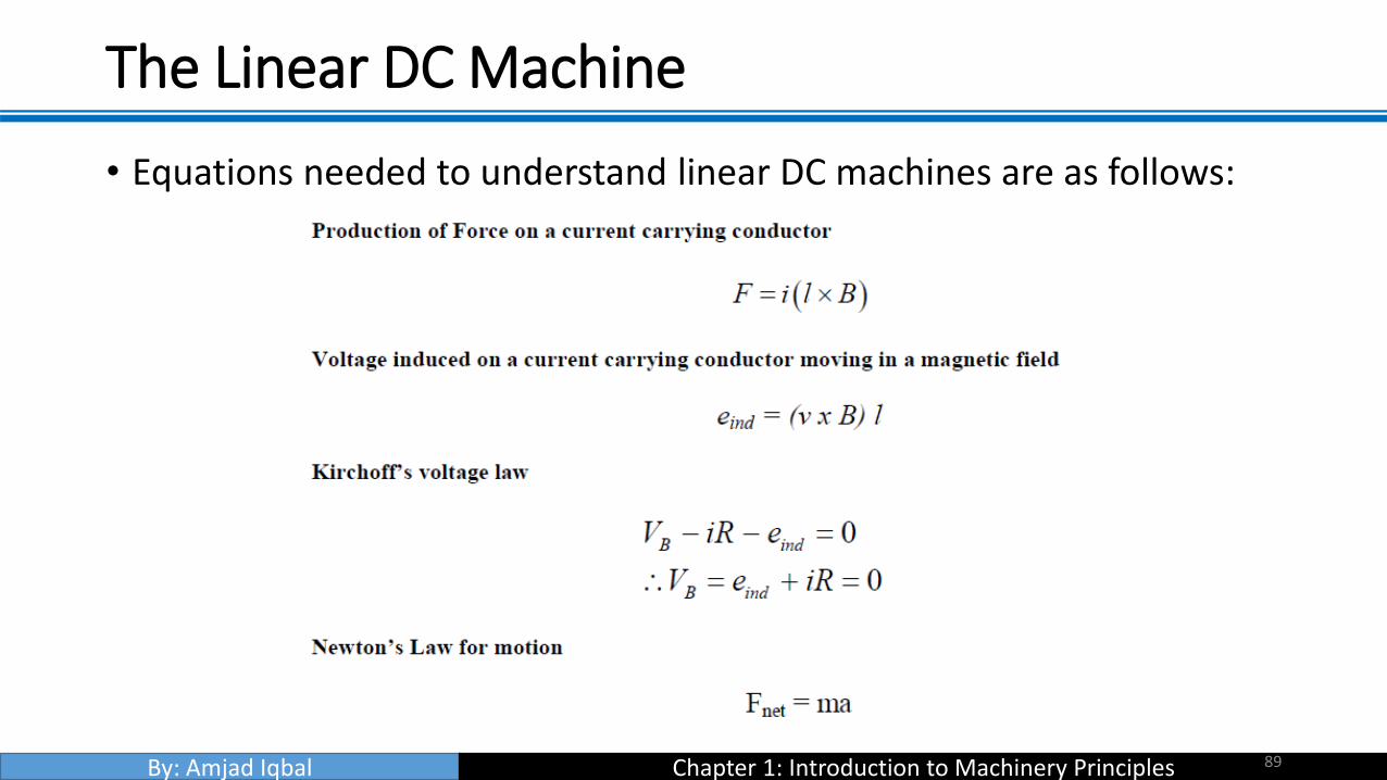
• Equations needed to understand linear DC machines are as follows:
89

By: Amjad Iqbal Chapter 1: Introduction to Machinery Principles
Starting the Linear DC Machine
• To start the machine, the switch is closed.
• Current will flow in the circuit and the equation can be derived from Kirchoff’s law:
• At this moment, the induced voltage is 0 due to no movement of the wire (the bar is at rest).
90

By: Amjad Iqbal Chapter 1: Introduction to Machinery Principles
Starting the Linear DC Machine
• As the current flows down through the bar, a force will be induced on the bar.
91
By: Amjad Iqbal Chapter 1: Introduction to Machinery Principles
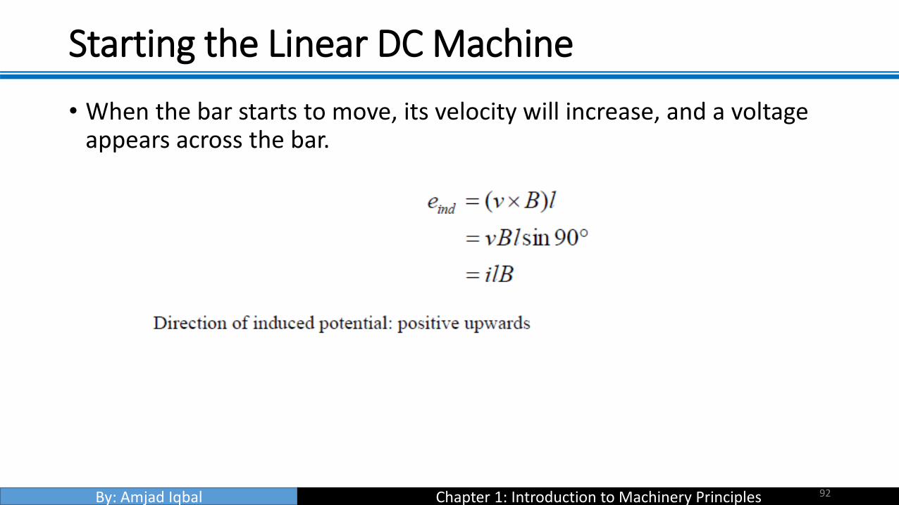
Starting the Linear DC Machine
• When the bar starts to move, its velocity will increase, and a voltage appears across the bar.
92

By: Amjad Iqbal Chapter 1: Introduction to Machinery Principles
Starting the Linear DC Machine
• Due to the presence of motion and induced potential (eind), the currentflowing in the bar will reduce (according to Kirchhoff’s voltage law). Theresult of this action is that eventually the bar will reach a constant steady-state speed where the net force on the bar is zero. This occurs when eind
has risen all the way up to equal VB. This is given by:
• The above equation is true assuming that R is very small. The bar willcontinue to move along at this no-load speed forever unless some externalforce disturbs it.
93

By: Amjad Iqbal Chapter 1: Introduction to Machinery Principles
Starting the Linear DC Machine
• Summarization of the starting of linear DC machine is sketched in the figure below:
94

By: Amjad Iqbal Chapter 1: Introduction to Machinery Principles
The Linear DC Machine as a Motor
• Assume the linear machine is initially running at the no-load steady state condition (as before).
• What happen when an external load is applied? See figure below:
95

By: Amjad Iqbal Chapter 1: Introduction to Machinery Principles
The Linear DC Machine as a Motor
• A force Fload is applied to the bar opposing the direction of motion. Since the bar was initially at steady state, application of the force Fload
will result in a net force on the bar in the direction opposite the direction of motion.
• Thus, the bar will slow down (the resulting acceleration a = Fnet/m is negative). As soon as that happen, the induced voltage on the bar drops (eind = v↓ Bl).
96

By: Amjad Iqbal Chapter 1: Introduction to Machinery Principles
The Linear DC Machine as a Motor
• When the induced voltage drops, the current flow in the bar will rise:
• Thus, the induced force will rise too. (Find ↑ = i↑ lB)
• Final result> the induced force will rise until it is equal and opposite to the load force, and the bar again travels in steady state condition, but at a lower speed.
97
By: Amjad Iqbal Chapter 1: Introduction to Machinery Principles
The Linear DC Machine as a Motor
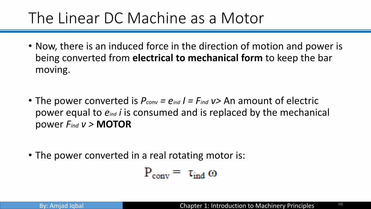
• Now, there is an induced force in the direction of motion and power is being converted from electrical to mechanical form to keep the bar moving.
• The power converted is Pconv = eind I = Find v> An amount of electric power equal to eind i is consumed and is replaced by the mechanical power Find v > MOTOR
• The power converted in a real rotating motor is:
98

By: Amjad Iqbal Chapter 1: Introduction to Machinery Principles
The Linear DC Machine as a Generator
• While the external force is applied on the moving direction
99

By: Amjad Iqbal Chapter 1: Introduction to Machinery Principles
The Linear DC Machine as a Generator
100
By: Amjad Iqbal Chapter 1: Introduction to Machinery Principles
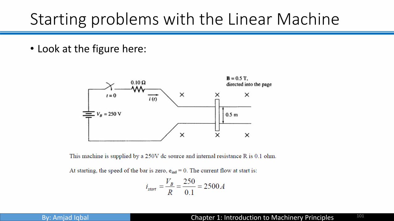
Starting problems with the Linear Machine
• Look at the figure here:
101

By: Amjad Iqbal Chapter 1: Introduction to Machinery Principles
Starting problems with the Linear Machine
102