dc machines - akademik.adu.edu.tr other words, the armature winding ... proportional to the voltage...
TRANSCRIPT
DC MACHINES

In rotating machines, voltages are generated in windings or groups of coils
• by rotating these windings mechanically through a magnetic field,
• by mechanically rotating a magnetic field past the winding,
• by designing the magnetic circuit so that the reluctance varies with rotation of the
rotor.
• By any of these methods, the flux linking a specific coil is changed cyclically, and a
time-varying voltage is generated.
A set of such coils connected together is typically referred to as an armature
winding.

• In general, the term armature winding is used to refer to a winding or a set of
windings on a rotating machine which carry ac currents.
• In ac machines such as synchronous or induction machines, the armature winding
is typically on the stationary portion of the motor referred to as the stator, in
which case these windings may also be referred to as stator windings.
• In a dc machine, the armature winding is found on the rotating member, referred
to as the rotor.
Elementary DC Machines
• The armature winding of a dc generator is on the rotor with current conducted from it by means of carbon brushes.
• The field winding is on the stator and is excited by direct current.
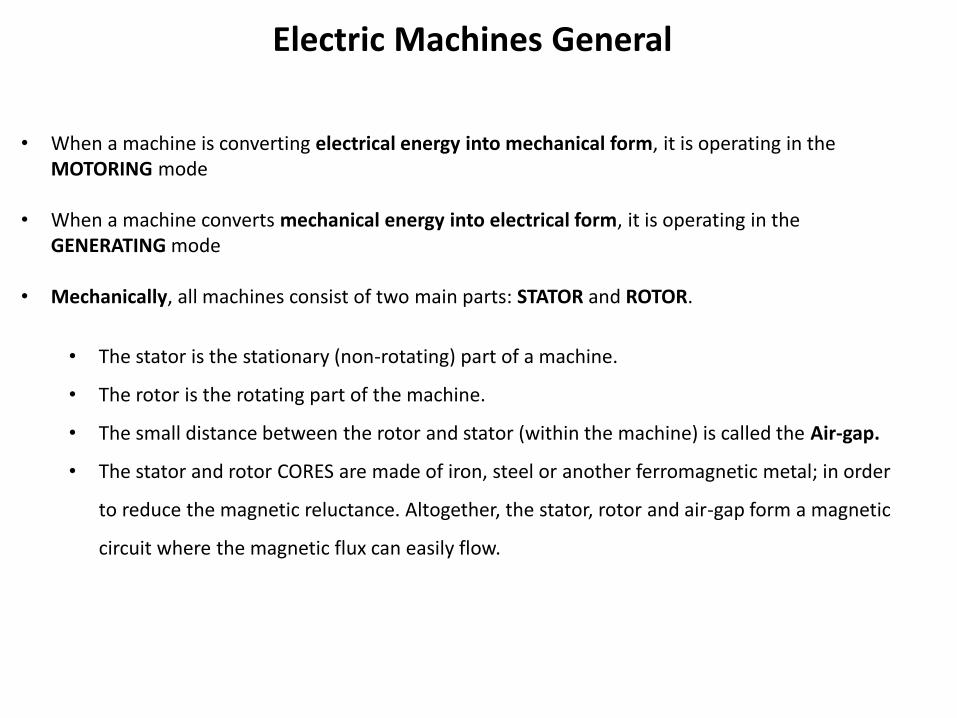
Electric Machines General
• When a machine is converting electrical energy into mechanical form, it is operating in the MOTORING mode
• When a machine converts mechanical energy into electrical form, it is operating in the GENERATING mode
• Mechanically, all machines consist of two main parts: STATOR and ROTOR.
• The stator is the stationary (non-rotating) part of a machine.
• The rotor is the rotating part of the machine.
• The small distance between the rotor and stator (within the machine) is called the Air-gap.
• The stator and rotor CORES are made of iron, steel or another ferromagnetic metal; in order
to reduce the magnetic reluctance. Altogether, the stator, rotor and air-gap form a magnetic
circuit where the magnetic flux can easily flow.
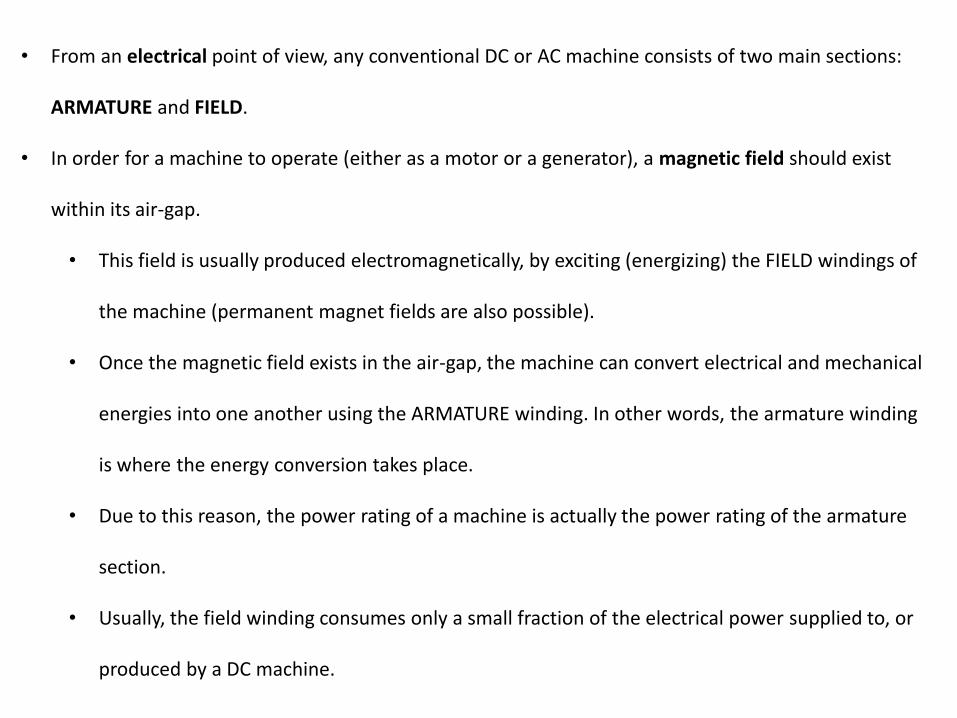
• From an electrical point of view, any conventional DC or AC machine consists of two main sections:
ARMATURE and FIELD.
• In order for a machine to operate (either as a motor or a generator), a magnetic field should exist
within its air-gap.
• This field is usually produced electromagnetically, by exciting (energizing) the FIELD windings of
the machine (permanent magnet fields are also possible).
• Once the magnetic field exists in the air-gap, the machine can convert electrical and mechanical
energies into one another using the ARMATURE winding. In other words, the armature winding
is where the energy conversion takes place.
• Due to this reason, the power rating of a machine is actually the power rating of the armature
section.
• Usually, the field winding consumes only a small fraction of the electrical power supplied to, or
produced by a DC machine.

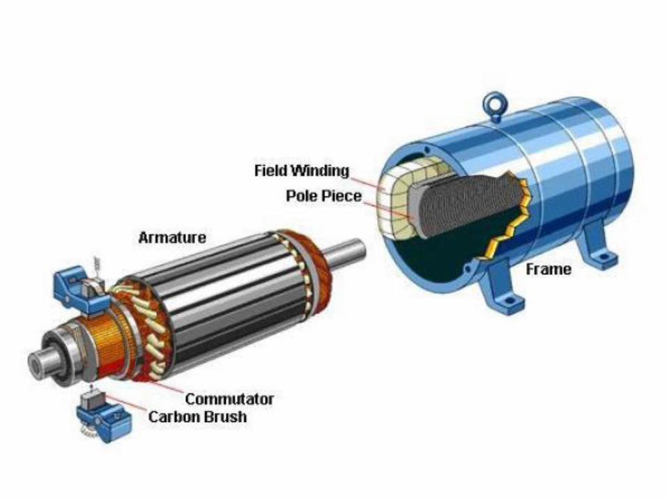
DC MACHINES
• In DC machines, the field winding is wound onto the stator, while the armature winding is located on the rotor.
• Current is supplied to the rotating armature winding through Commutator Segments.
• Each commutator segment (also located on the rotor) is connected to an armature winding coil.
• Mounted on the stator are carbon BRUSHES, which actually touch two or more of the commutator segments
at a time.
• To operate a DC machine as a MOTOR:
• A DC current should pass through the FIELD winding.
• This current can be supplied either from the armature winding’s DC source, or from another source such as a
battery.
• Electrical power should be supplied to the ARMATURE winding from a DC source.
• The mechanical power produced by the motor can be used to drive a mechanical load (e.g., the wheels of an
electric car) coupled to the motor shaft.
• The speed of the shaft will be directly proportional to the armature voltage, and inversely proportional to
the field current.
• The torque produced will be directly proportional to the armature current and field current.
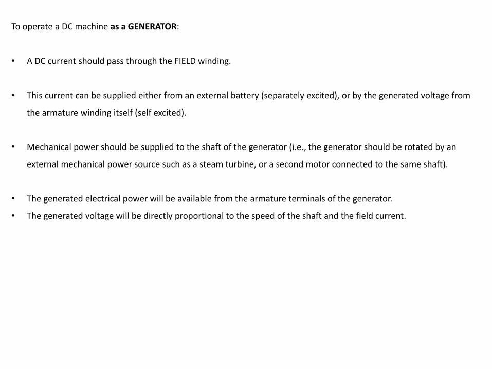
To operate a DC machine as a GENERATOR:
• A DC current should pass through the FIELD winding.
• This current can be supplied either from an external battery (separately excited), or by the generated voltage from
the armature winding itself (self excited).
• Mechanical power should be supplied to the shaft of the generator (i.e., the generator should be rotated by an
external mechanical power source such as a steam turbine, or a second motor connected to the same shaft).
• The generated electrical power will be available from the armature terminals of the generator.
• The generated voltage will be directly proportional to the speed of the shaft and the field current.

• An electric motor CANNOT be considered as a passive electrical load.
• In a passive load (such as a resistor or an inductor), the current flowing into the load will be
proportional to the voltage applied across its terminals (i.e., V=Zload.I).
• THIS IS NOT THE CASE FOR AN ELECTRICAL MACHINE!!!
• The armature current and armature voltage of an electric motor are completely independent!
• The armature current is determined by the mechanical load (i.e., torque) the motor is
driving, which is not related to the voltage applied to the armature.
• The same reasoning also applies to DC generators.
• For the generating mode, the current drawn from the armature terminals is independent of
the armature voltage.
• An increase in the output current (i.e., output power) should be compensated by increasing
the mechanical torque (i.e., input power) on the shaft.
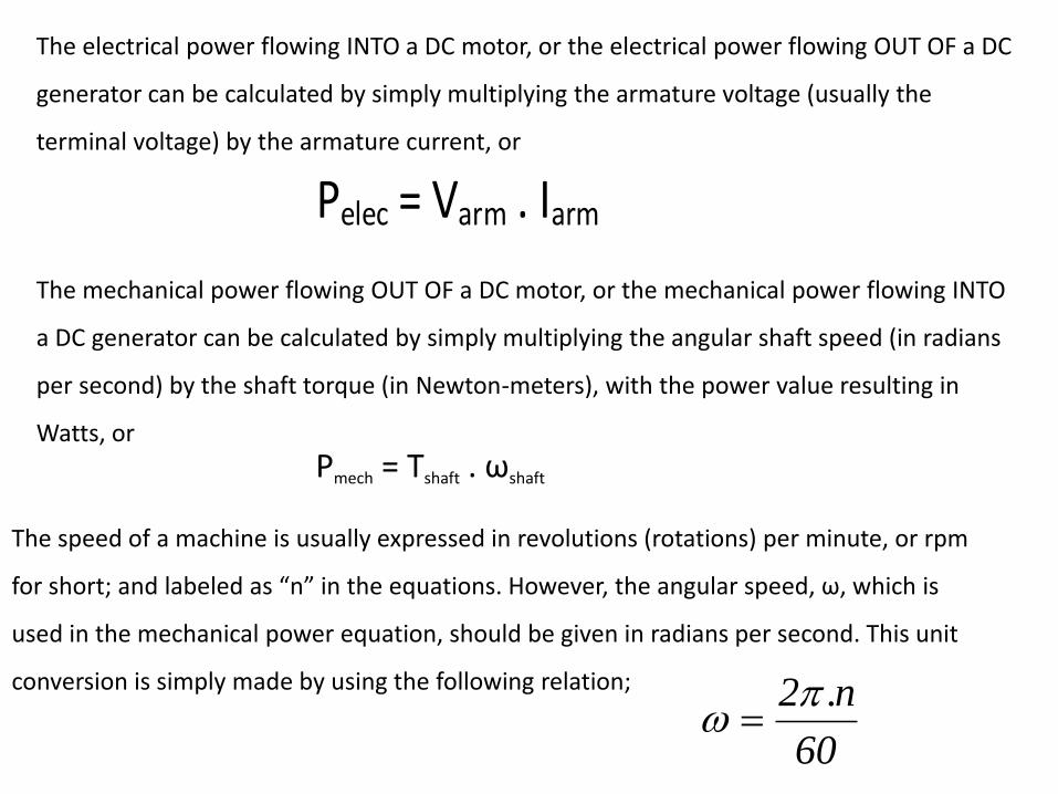
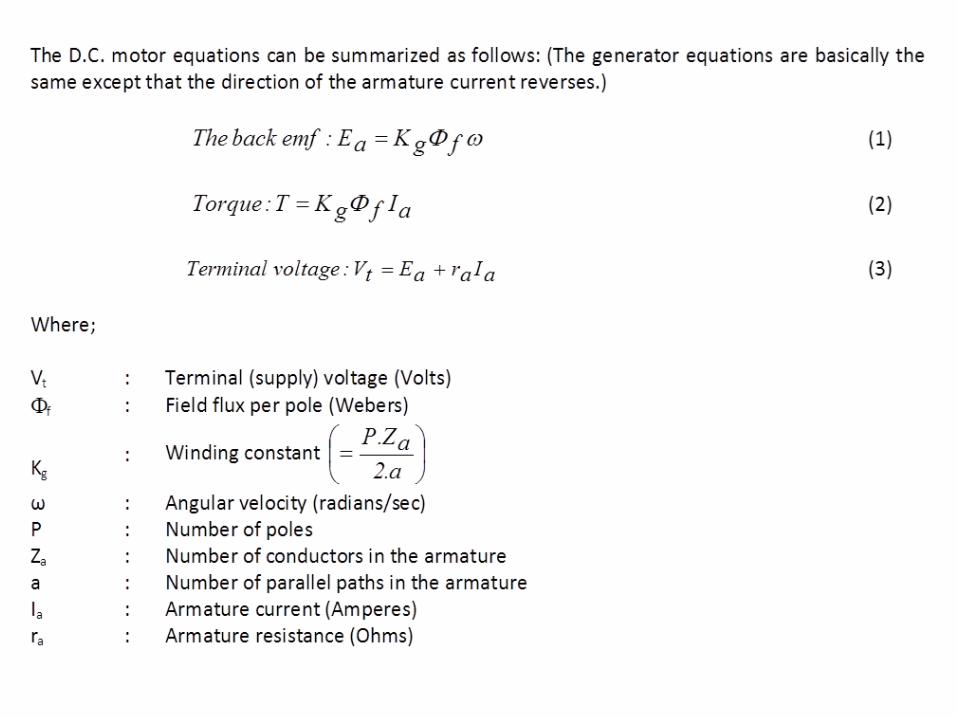
The electrical power flowing INTO a DC motor, or the electrical power flowing OUT OF a DC
generator can be calculated by simply multiplying the armature voltage (usually the
terminal voltage) by the armature current, or
Pelec = Varm . Iarm
The mechanical power flowing OUT OF a DC motor, or the mechanical power flowing INTO
a DC generator can be calculated by simply multiplying the angular shaft speed (in radians
per second) by the shaft torque (in Newton-meters), with the power value resulting in
Watts, or
Pmech = Tshaft . ωshaft
The speed of a machine is usually expressed in revolutions (rotations) per minute, or rpm
for short; and labeled as “n” in the equations. However, the angular speed, ω, which is
used in the mechanical power equation, should be given in radians per second. This unit
conversion is simply made by using the following relation;
60
n.2
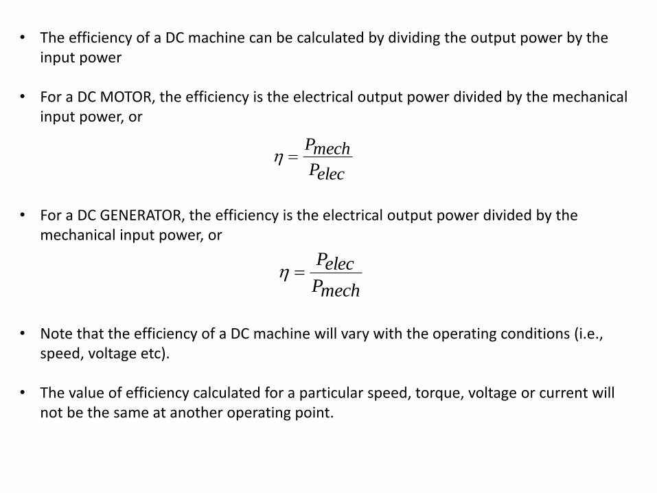
• The efficiency of a DC machine can be calculated by dividing the output power by the input power
• For a DC MOTOR, the efficiency is the electrical output power divided by the mechanical input power, or
• For a DC GENERATOR, the efficiency is the electrical output power divided by the
mechanical input power, or • Note that the efficiency of a DC machine will vary with the operating conditions (i.e.,
speed, voltage etc).
• The value of efficiency calculated for a particular speed, torque, voltage or current will not be the same at another operating point.
elecP
mechP
mechP
elecP
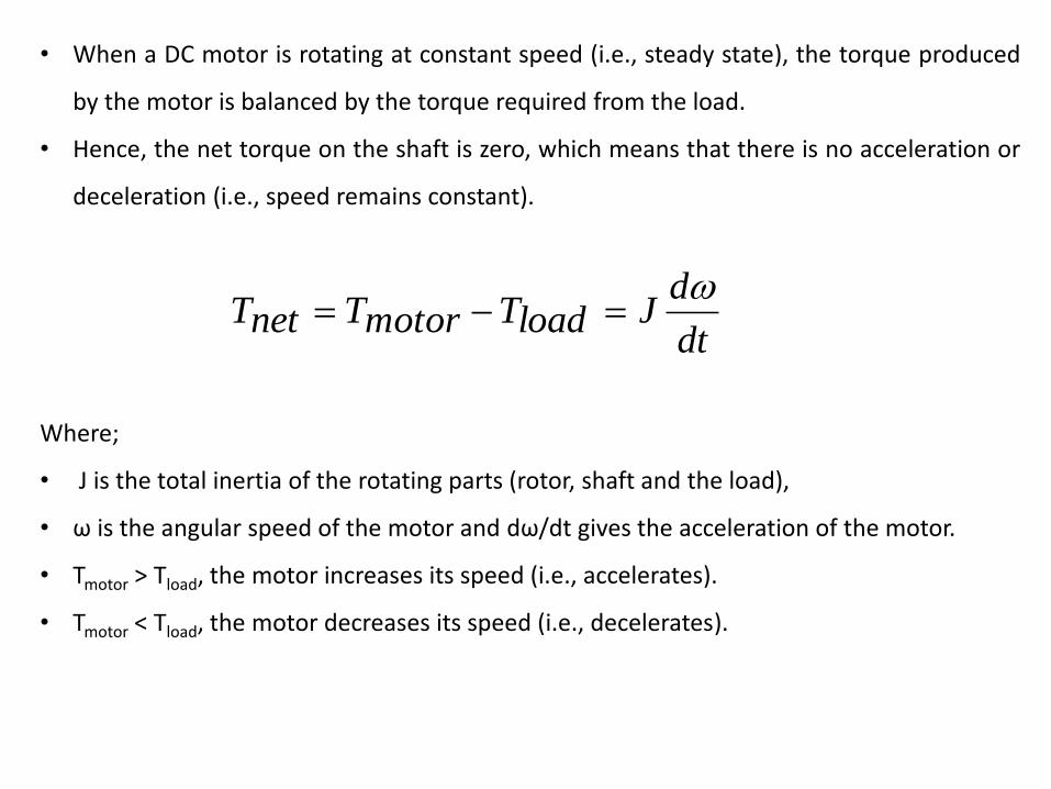
• When a DC motor is rotating at constant speed (i.e., steady state), the torque produced
by the motor is balanced by the torque required from the load.
• Hence, the net torque on the shaft is zero, which means that there is no acceleration or
deceleration (i.e., speed remains constant).
Where;
• J is the total inertia of the rotating parts (rotor, shaft and the load),
• ω is the angular speed of the motor and dω/dt gives the acceleration of the motor.
• Tmotor > Tload, the motor increases its speed (i.e., accelerates).
• Tmotor < Tload, the motor decreases its speed (i.e., decelerates).
dt
dJloadTmotorTnetT
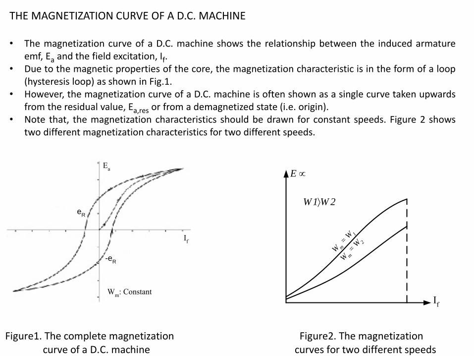
THE MAGNETIZATION CURVE OF A D.C. MACHINE • The magnetization curve of a D.C. machine shows the relationship between the induced armature
emf, Ea and the field excitation, If. • Due to the magnetic properties of the core, the magnetization characteristic is in the form of a loop
(hysteresis loop) as shown in Fig.1. • However, the magnetization curve of a D.C. machine is often shown as a single curve taken upwards
from the residual value, Ea,res or from a demagnetized state (i.e. origin). • Note that, the magnetization characteristics should be drawn for constant speeds. Figure 2 shows
two different magnetization characteristics for two different speeds.
Ea
If
eR
-eR
Wm
: Constant
2W1W
E
W m =
W1
W m =
W2
If
Figure1. The complete magnetization Figure2. The magnetization curve of a D.C. machine curves for two different speeds

The induced emf across the armature winding of a D.C. machines is a function of rotor speed, wm and field current, If (see Figure 2).
fI m Mm p aKaE
Ea: Induced back-emf across the armature winding (Volts) Ka: Winding constant φp: Flux per pole (Webers) wm: Rotor speed (radians/sec) M: Mutual inductance (Henry) If: Field current (Amperes)
THE LOAD CHARACTERISTICS
OF
SERIES, SHUNT AND COMPOUND D.C. GENERATORS

Direct current machines may be magnetized in two different ways: • They may be magnetized by supplying current to the field winding from a separate D.C.
source, such as a battery, etc. This type of excitation is called separate excitation.
• They may generate their own magnetizing currents. This type of excitation is called self excitation. Such machines may have their field windings connected
• in parallel with the armature circuit : shunt connection • in series with the armature circuit :, series connection • both shunt and series field windings may be used : compound connection
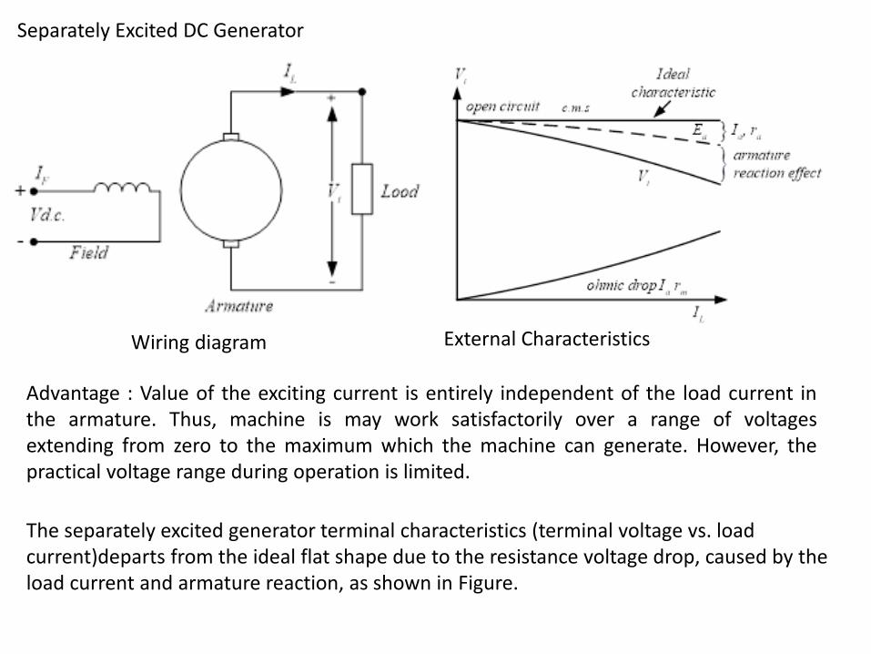
Wiring diagram
Separately Excited DC Generator
External Characteristics
Advantage : Value of the exciting current is entirely independent of the load current in the armature. Thus, machine is may work satisfactorily over a range of voltages extending from zero to the maximum which the machine can generate. However, the practical voltage range during operation is limited.
The separately excited generator terminal characteristics (terminal voltage vs. load current)departs from the ideal flat shape due to the resistance voltage drop, caused by the load current and armature reaction, as shown in Figure.

• number of turns in the field winding is large, the field winding resistance is higher, and the rated field current is lower that of the other types.
The shunt generator has a more drooping characteristics than the separately excided generator. This is because as the machine is loaded, the terminal voltage decreases (as in the case of a separately excited generator). This, in turn, also decreases the field current which reduces the generated emf, causing a larger voltage drop in the terminal voltage than that would be observed in the case of a separately excited generator.
Self-Excited Shunt Generator
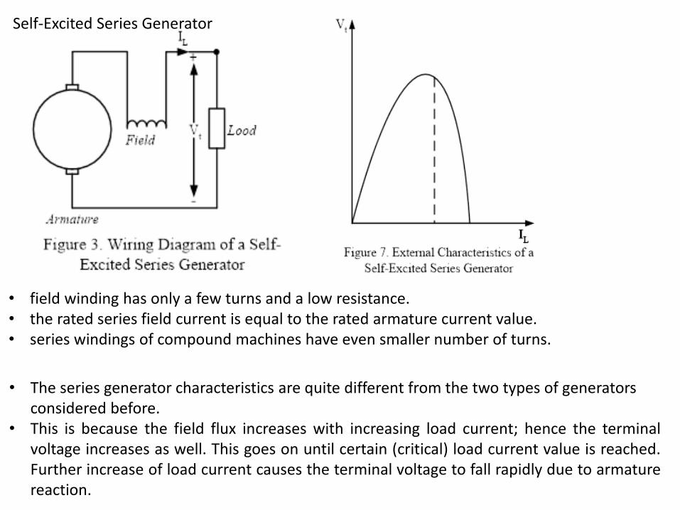
• field winding has only a few turns and a low resistance. • the rated series field current is equal to the rated armature current value. • series windings of compound machines have even smaller number of turns.
• The series generator characteristics are quite different from the two types of generators considered before.
• This is because the field flux increases with increasing load current; hence the terminal voltage increases as well. This goes on until certain (critical) load current value is reached. Further increase of load current causes the terminal voltage to fall rapidly due to armature reaction.
Self-Excited Series Generator

• A compound generator has both series and shunt field windings. • The short-shunt connection, where the shunt field is connected in parallel to the
armature, is shown in Figure 4. • If the shunt field winding is connected in parallel to the load, it is called the long-shunt
connection. • The polarity (direction) of the series field is also important. The series winding may be
connected such that it may strengthen the shunt field (additive compounding) or that it may weaken the shunt field (subtractive compounding).
• In practice, subtractive compounding is used very exceptionally.
Compound Generator
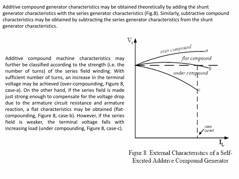
Additive compound generator characteristics may be obtained theoretically by adding the shunt generator characteristics with the series generator characteristics (Fig.8). Similarly, subtractive compound characteristics may be obtained by subtracting the series generator characteristics from the shunt generator characteristics.
Additive compound machine characteristics may further be classified according to the strength (i.e. the number of turns) of the series field winding. With sufficient number of turns, an increase in the terminal voltage may be achieved (over-compounding, Figure 8, case-a). On the other hand, if the series field is made just strong enough to compensate for the voltage drop due to the armature circuit resistance and armature reaction, a flat characteristics may be obtained (flat-compounding, Figure 8, case-b). However, if the series field is weaker, the terminal voltage falls with increasing load (under compounding, Figure 8, case-c).
THE LOAD CHARACTERISTICS
OF
SERIES, SHUNT AND COMPOUND D.C. MOTORS
When D.C. motors are operated from a constant voltage source, a wide range of torque-speed characteristics can be obtained, depending on the motor type. The series motor is a variable speed motor, whose speed varies with load. Its ability to slow down while large load torque is applied reduces its power demand from the line. On the other hand, the shunt motor is essentially a constant speed motor. The compound motor characteristic is composed of its shunt and series winding characteristics. One could call it an “adjustable speed motor”. The exact characteristics depend on the strengths of the shunt and series windings fields at full load.

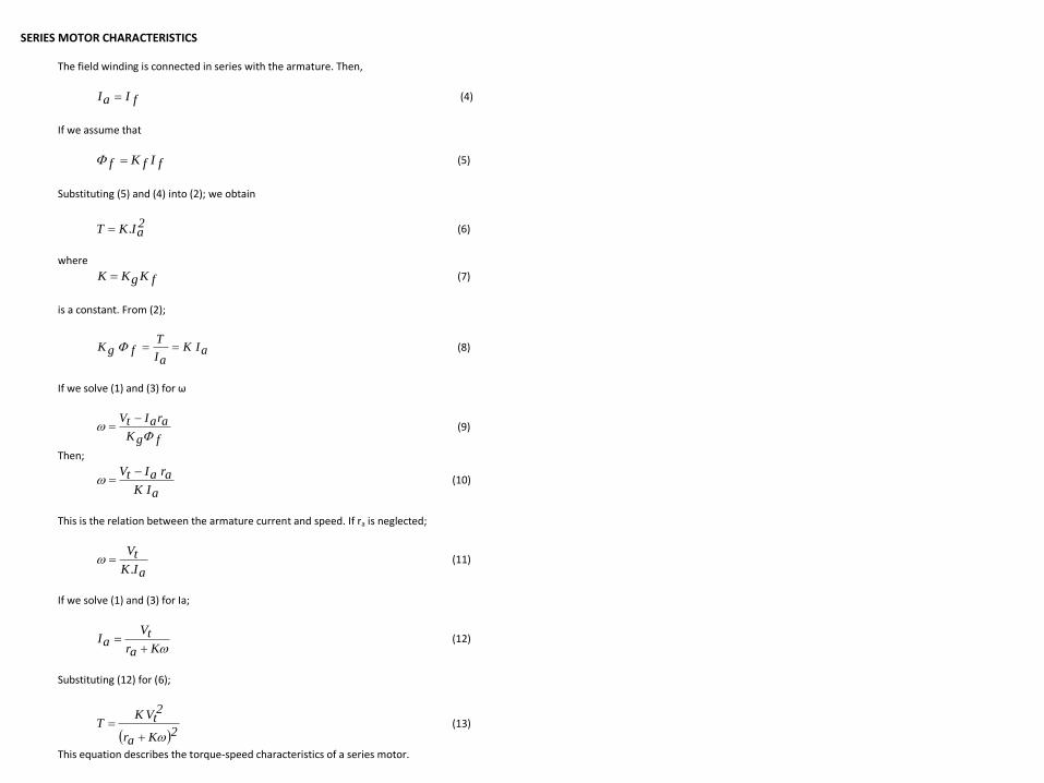
SERIES MOTOR CHARACTERISTICS The field winding is connected in series with the armature. Then,
fIaI (4)
If we assume that
fIfKf (5)
Substituting (5) and (4) into (2); we obtain
2aI.KT (6)
where
fKgKK (7)
is a constant. From (2);
aI KaI
Tf gK (8)
If we solve (1) and (3) for ω
fgK
araItV
(9)
Then;
aI K
ar aItV (10)
This is the relation between the armature current and speed. If ra is neglected;
aI.K
tV (11)
If we solve (1) and (3) for Ia;
Kar
tVaI
(12)
Substituting (12) for (6);
2Kar
2tV K
T
(13)
This equation describes the torque-speed characteristics of a series motor.
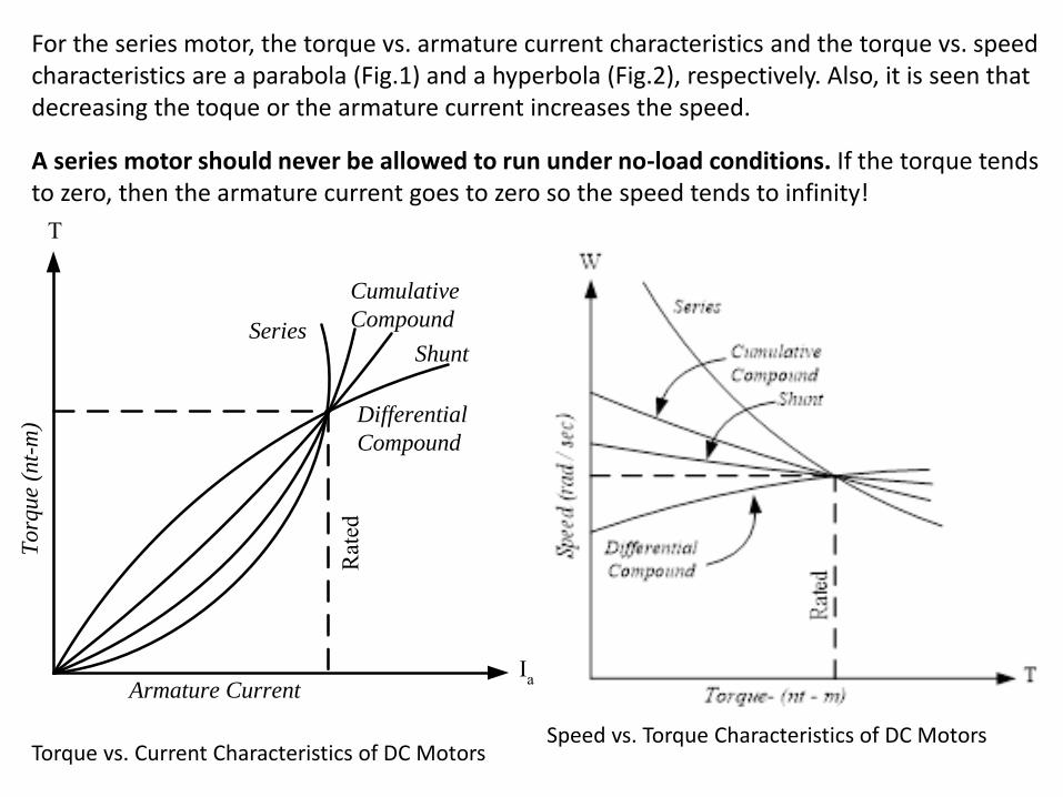
For the series motor, the torque vs. armature current characteristics and the torque vs. speed characteristics are a parabola (Fig.1) and a hyperbola (Fig.2), respectively. Also, it is seen that decreasing the toque or the armature current increases the speed. A series motor should never be allowed to run under no-load conditions. If the torque tends to zero, then the armature current goes to zero so the speed tends to infinity!
Series
Cumulative
Compound
Shunt
Differential
Compound
Armature Current
Rat
ed
To
rqu
e (n
t-m
)
Ia
T
Figure1. Torque vs. Current Characteristics of D.C. Motors
Torque vs. Current Characteristics of DC Motors Speed vs. Torque Characteristics of DC Motors
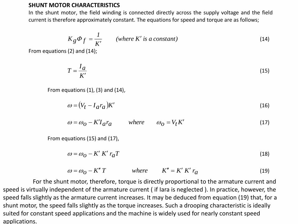
SHUNT MOTOR CHARACTERISTICS In the shunt motor, the field winding is connected directly across the supply voltage and the field current is therefore approximately constant. The equations for speed and torque are as follows;
constant) a is K (where K
1fgK
(14)
From equations (2) and (14);
K
aIT
(15)
From equations (1), (3) and (14),
KaraItV (16)
KtVo where araIKo (17)
From equations (15) and (17),
Tar K Ko (18)
ar K KK e wher T Ko (19)
For the shunt motor, therefore, torque is directly proportional to the armature current and speed is virtually independent of the armature current ( if Iara is neglected ). In practice, however, the speed falls slightly as the armature current increases. It may be deduced from equation (19) that, for a shunt motor, the speed falls slightly as the torque increases. Such a drooping characteristic is ideally suited for constant speed applications and the machine is widely used for nearly constant speed applications.
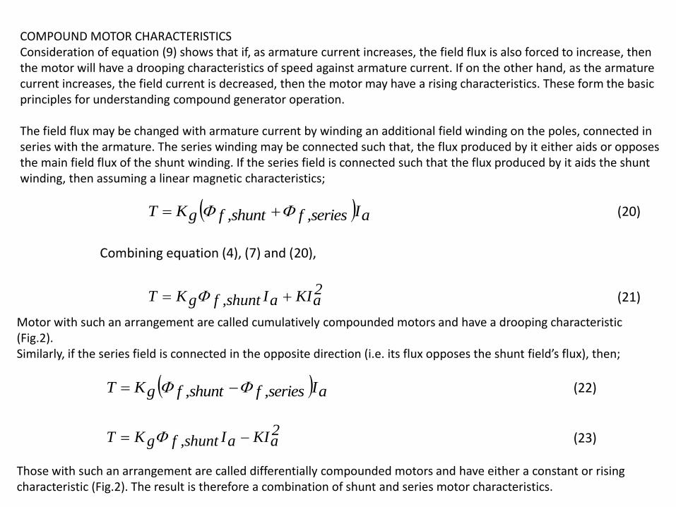
COMPOUND MOTOR CHARACTERISTICS Consideration of equation (9) shows that if, as armature current increases, the field flux is also forced to increase, then the motor will have a drooping characteristics of speed against armature current. If on the other hand, as the armature current increases, the field current is decreased, then the motor may have a rising characteristics. These form the basic principles for understanding compound generator operation. The field flux may be changed with armature current by winding an additional field winding on the poles, connected in series with the armature. The series winding may be connected such that, the flux produced by it either aids or opposes the main field flux of the shunt winding. If the series field is connected such that the flux produced by it aids the shunt winding, then assuming a linear magnetic characteristics;
aIseries,fshunt,fgKT (20)
Combining equation (4), (7) and (20),
2aKIaIshunt,fgKT (21) Motor with such an arrangement are called cumulatively compounded motors and have a drooping
characteristic (Fig.2). Similarly, if the series field is connected in the opposite direction (i.e. its flux opposes the shunt field’s flux), then;
aIseries,fshunt,fgKT (22)
2aKIaIshunt,fgKT (23)
Those with such an arrangement are called differentially compounded motors and have either a constant or rising characteristic (Fig.2). The result is therefore a combination of shunt and series motor characteristics.
Motor with such an arrangement are called cumulatively compounded motors and have a drooping characteristic (Fig.2). Similarly, if the series field is connected in the opposite direction (i.e. its flux opposes the shunt field’s flux), then;
Those with such an arrangement are called differentially compounded motors and have either a constant or rising characteristic (Fig.2). The result is therefore a combination of shunt and series motor characteristics.
IMPORTANT NOTE In differentially-compounded motors, during starting, the field weakening effect of the series winding may be sufficiently great to cause instability or run-away. This winding should therefore be shorted out while the motor is started.
References: Fitzgerald& Kingsley’s Electric Machinery, McGraw-Hill EE 361 laboratory manual and lecture notes, Middle East Technical University