dc motor control
DESCRIPTION
jst try 2 make easy n approch of sum1's best ideasTRANSCRIPT
DC Motor interfacing with Microcontrollers tutorial
►Introduction
Whenever a robotics hobbyist talk about making a robot, the first thing comes to his mind is making the robot move on the ground. And there are always two options in front of the designer whether to use a DC motor or a stepper motor. When it comes to speed, weight, size, cost... DC motors are always preffered over stepper motors. There are many things which you can do with your DC motor when interfaced with a microcontroller. For example you can control the speed of motor, you can control the direction of rotation, you can also do encoding of the rotation made by DC motor i.e. keeping track of how many turns are made by your motors etc. So you can see DC motors are no less than a stepper motor.
In this part of tutorial we will learn to interfacing a DC motor with a microcontroller. Usually H-bridge is preffered way of interfacing a DC motor. These days many IC manufacturers have H-bridge motor drivers available in the market like L293D is most used H-Bridge driver IC. H-bridge can also be made with the help of trasistors and MOSFETs etc. rather of being cheap, they only increase the size of the design board, which is somtimes not required so using a small 16 pin IC is preffered for this purpose.
►Working Theory of H-Bridge
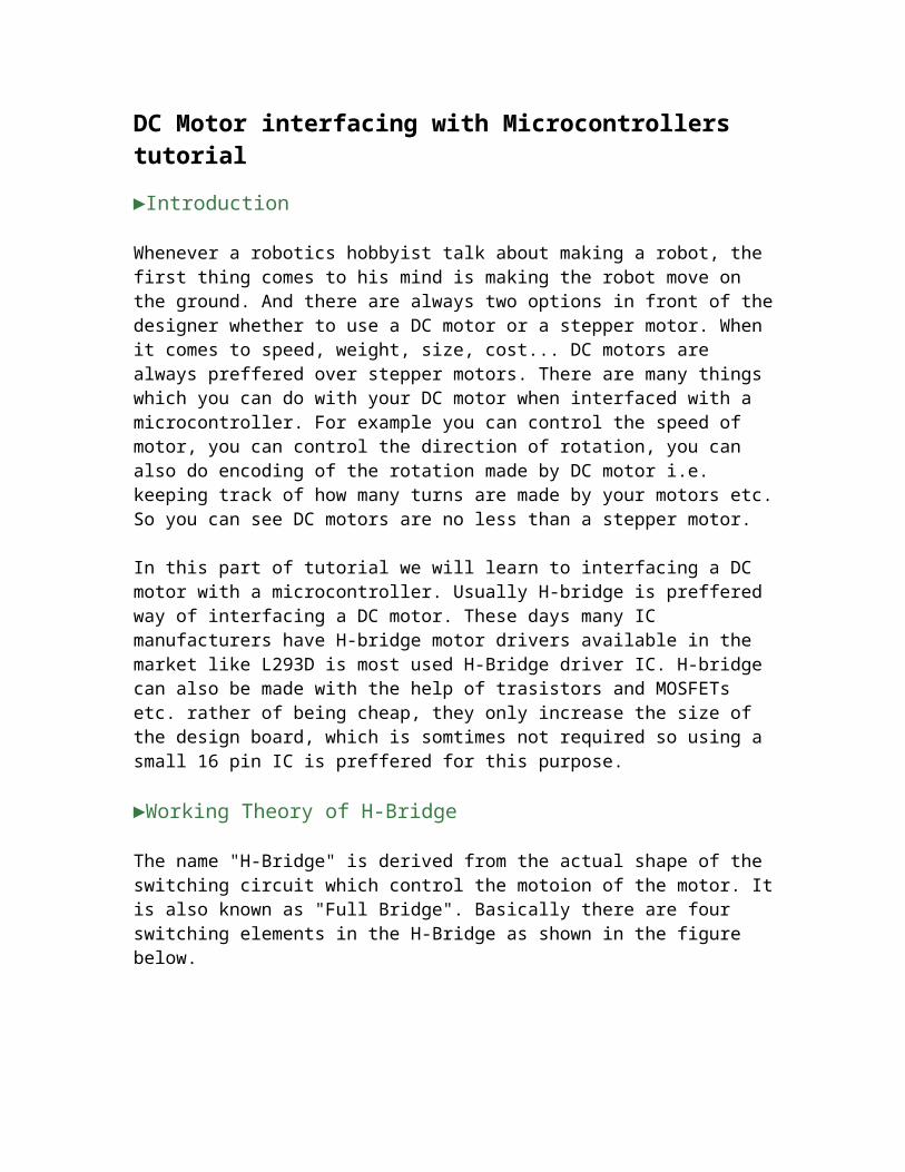
The name "H-Bridge" is derived from the actual shape of the switching circuit which control the motoion of the motor. It is also known as "Full Bridge". Basically there are four switching elements in the H-Bridge as shown in the figure below.
As you can see in the figure above there are four switching elements named as "High side
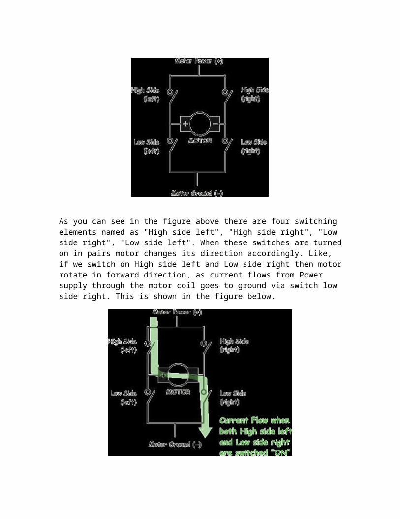
left", "High side right", "Low side right", "Low side left". When these switches are turned on in pairs motor changes its direction accordingly. Like, if we switch on High side left and Low side right then motor rotate in forward direction, as current flows from Power supply through the motor coil goes to ground via switch low side right. This is shown in the figure below.
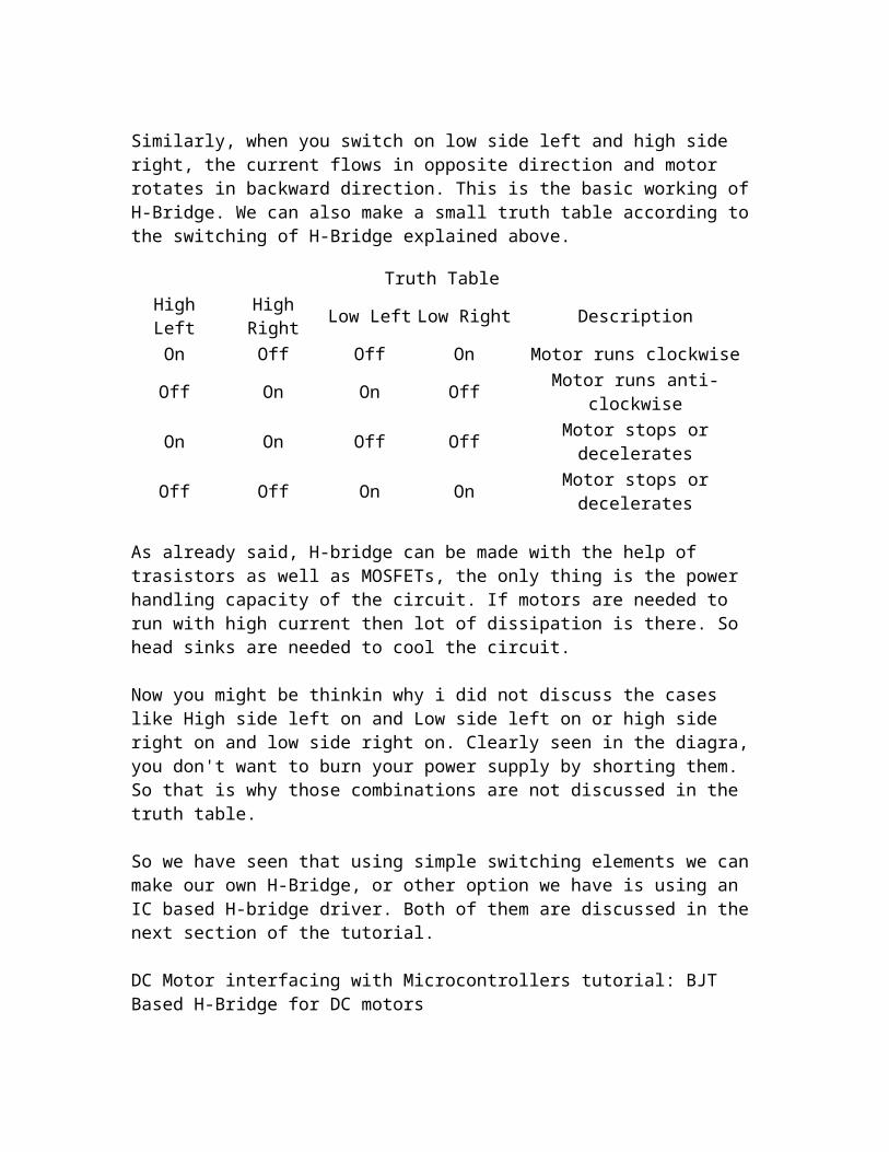
Similarly, when you switch on low side left and high side right, the current flows in opposite direction and motor rotates in backward direction. This is the basic working of H-Bridge. We can also make a small truth table according to the switching of H-Bridge explained above.
Truth TableHigh Left High Right Low Left Low Right Description
On Off Off On Motor runs clockwiseOff On On Off Motor runs anti-clockwiseOn On Off Off Motor stops or deceleratesOff Off On On Motor stops or decelerates
As already said, H-bridge can be made with the help of trasistors as well as MOSFETs, the only thing is the power handling capacity of the circuit. If motors are needed to run with high current then lot of dissipation is there. So head sinks are needed to cool the circuit.
Now you might be thinkin why i did not discuss the cases like High side left on and Low side left on or high side right on and low side right on. Clearly seen in the diagra, you don't want to burn your power supply by shorting them. So that is why those combinations are not discussed in the truth table.
So we have seen that using simple switching elements we can make our own H-Bridge, or other option we have is using an IC based H-bridge driver. Both of them are discussed in the next section of the tutorial.
DC Motor interfacing with Microcontrollers tutorial: BJT Based H-Bridge for DC motors
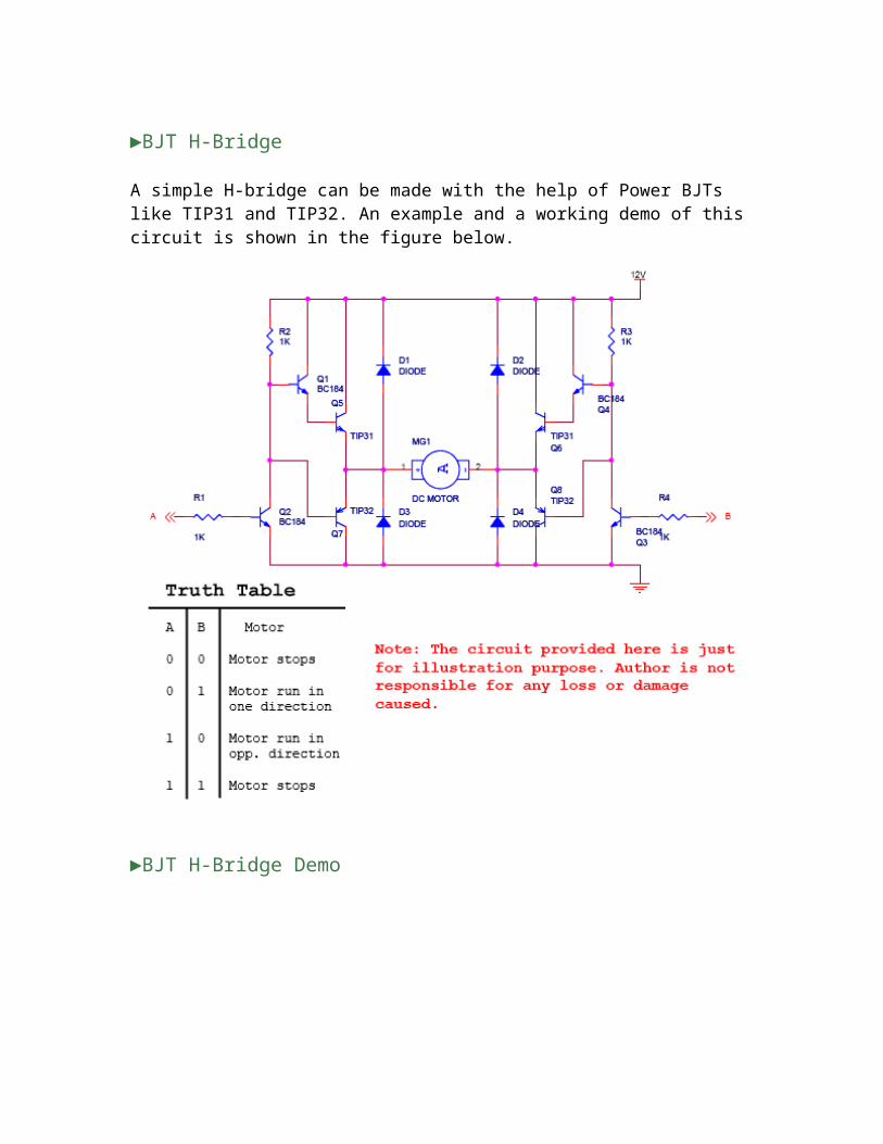
►BJT H-Bridge
A simple H-bridge can be made with the help of Power BJTs like TIP31 and TIP32. An example and a working demo of this circuit is shown in the figure below.
►BJT H-Bridge Demo
C Motor interfacing with Microcontrollers tutorial: L293D H-Bridge interfacing
►L293D Dual H-Bridge Motor Driver
L293D is a dual H-Bridge motor driver, So with one IC we can interface two DC motors which can be controlled in both clockwise and counter clockwise direction and if you have motor with fix direction of motion the you can make use of all the four I/Os to connect up to four DC motors. L293D has output current of 600mA and peak output current of 1.2A per channel. Moreover for protection of circuit from back EMF ouput diodes are included within the IC. The output supply (VCC2) has a wide range from 4.5V to 36V, which has made L293D a best choice for DC motor driver.
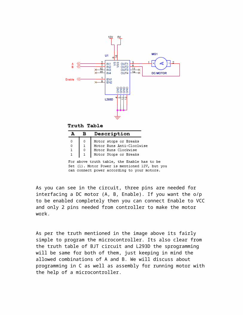
A simple schematic for interfacing a DC motor using L293D is shown below.

As you can see in the circuit, three pins are needed for interfacing a DC motor (A, B, Enable). If you want the o/p to be enabled completely then you can connect Enable to VCC and only 2 pins needed from controller to make the motor work.
As per the truth mentioned in the image above its fairly simple to program the microcontroller. Its also clear from the truth table of BJT circuit and L293D the sprogramming will be same for both of them, just keeping in mind the allowed combinations of A and B. We will discuss about programming in C as well as assembly for running motor with the help of a microcontroller.
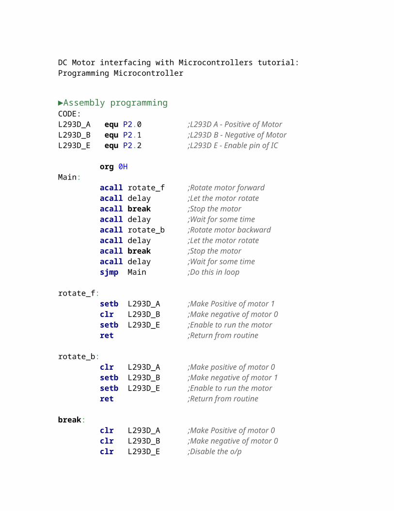
DC Motor interfacing with Microcontrollers tutorial: Programming Microcontroller
►Assembly programmingCODE:
L293D_A equ P2.0 ;L293D A - Positive of MotorL293D_B equ P2.1 ;L293D B - Negative of MotorL293D_E equ P2.2 ;L293D E - Enable pin of IC
org 0HMain: acall rotate_f ;Rotate motor forward acall delay ;Let the motor rotate acall break ;Stop the motor acall delay ;Wait for some time acall rotate_b ;Rotate motor backward acall delay ;Let the motor rotate acall break ;Stop the motor acall delay ;Wait for some time sjmp Main ;Do this in loop rotate_f: setb L293D_A ;Make Positive of motor 1 clr L293D_B ;Make negative of motor 0 setb L293D_E ;Enable to run the motor ret ;Return from routine rotate_b: clr L293D_A ;Make positive of motor 0 setb L293D_B ;Make negative of motor 1 setb L293D_E ;Enable to run the motor ret ;Return from routine break: clr L293D_A ;Make Positive of motor 0 clr L293D_B ;Make negative of motor 0 clr L293D_E ;Disable the o/p ret ;Return from routine delay: ;Some Delay mov r7,#20Hback: mov r6,#FFHback1: mov r5,#FFHhere: djnz r5, here djnz r6, back1 djnz r7, back ret
C programming
#include <AT89X51.H>#define L293D_A P2_0 //Positive of motor#define L293D_B P2_1 //Negative of motor#define L293D_E P2_2 //Enable of L293D
// Function Prototypesvoid rotate_f(void); //Forward run funtionvoid rotate_b(void); //Backward run functionvoid breaks(void); //Motor stop functionvoid delay(void); //Some delay
void main(){ //Our main function while(1){ //Infinite loop rotate_f(); //Run forward delay(); //Some delay breaks(); //Stop delay(); //Some delay rotate_b(); //Run Backwards delay(); //Some delay breaks(); //Stop delay(); //Some delay } //Do this infinitely}
void rotate_f(){ L293D_A = 1; //Make positive of motor 1 L293D_B = 0; //Make negative of motor 0 L293D_E = 1; //Enable L293D}
void rotate_b(){ L293D_A = 0; //Make positive of motor 0 L293D_B = 1; //Make negative of motor 1 L293D_E = 1; //Enable L293D}
void breaks(){ L293D_A = 0; //Make positive of motor 0 L293D_B = 0; //Make negative of motor 0 L293D_E = 0; //Disable L293D}
void delay(){ //Some delay... unsigned char i,j,k; for(i=0;i<0x20;i++)

for(j=0;j<255;j++) for(k=0;k<255;k++);}