dc to ac pure sine power inverter with automatic …
TRANSCRIPT

DC TO AC PURE SINE POWER INVERTER WITH AUTOMATIC TRANSFER SWITCH
PWRIX120012SUL / PWRIX200012SUL
INSTRUCTION MANUAL ETL Listed to UL 458 and CSA 22.2 NO 107.1
A. INTRODUCTIONThe AIMS Power pure sine inverter with transfer switch is used for back-up or off grid power applications. The inverter outputs pure sine power, which is ideal forsensitive equipment and provides clean efficient power. A power invertertransforms DC (direct current) electricity into AC (alternating current) power that can be used for running a wide variety of tools and appliances using a battery.This inverter is perfect for providing mobile power in cars and work trucks. The inverter also includes an automatic transfer switch that switches from shore to inverter power, automatcially commonly used in an RV or boat.
Read this instruction manual carefully and make sure your inverter is installedproperly before using.
B.WARNING AND SAFETY1. Keep this manual for future reference.2. Do not put the inverter under direct sunlight or near a heating source.3. The case of the inverter will get hot when used. Do not allow flammable materials
to contact the inverter, such as clothing, sleeping bags, carpet or any otherflammable materials. The heat from the inverter can damage these items.
4. The power inverter is designed to be used with a negative ground electricalsystem! Don't use with positive ground electrical systems (the majority of modernautomobiles, RVs, trucks and boats are negative ground).
5. Do not disassemble the unit: it may cause fire or electric shock.6. This device should only be serviced by a qualified technician. This item does not
have any serviceable parts.7. Prevent body contact with grounded surfaces such as pipes, radiators, ranges,
and refrigerator enclosures during installation.8. Do not operate the inverter if under the influence of alcohol or drugs. Read
warning labels on prescriptions to determine if your judgment or reflexes areimpaired while taking drugs. If there is any doubt, do not operate the inverter.
9. People with pacemakers should consult their physician(s) before using thisproduct. Electromagnetic fields in close proximity to a pacemaker could causeinterference to or failure of the pacemaker.
10. Keep the inverter well-ventilated. Do not place any objects on top of or next tothe inverter or allow anything to cover the cooling fans; doing so can cause theinverter to overheat, causing a potential fire hazard and/or damage to the
inverter. Leave adequate ventilation space underneath the inverter as well; thick carpets or rugs can obstruct air flow, causing the inverter to overheat.
11. Avoid unintentional starting. Be sure the switch is in the OFF position when not inuse and before plugging in any appliance.
12. Keep inverter away from children. Don't install the inverter where it is accessibleto children.
13. The power inverter will output the same AC power as utility power, please treatthe AC outlets as carefully as you would your home AC outlets. Do not putanything other than an electrical appliance into the output terminal. It may causeshock or fire.
14. Disconnect the battery and inverter when not in use.
Note: Performance of this unit may vary depending on the available battery power or appliance wattage.
Warning: The warnings, cautions, and instructions discussed in this instruction manual cannot cover all possible conditions and situations that may occur. It must be understood by the operator that common sense and caution are factors which cannot be built into this product, but must be supplied by operator. Guard against electric shock. Do not open the metal case; risk of electric shock.
C. INVERTER FEATURES• Automatic built in transfer switch / bypass (note rated
bypass amperage)• LED protect indicator• LED power indicator• Easy push on/off switch• Remote port for on/off remote switch (optional)• Thermally controlled cooling fan• Low battery voltage warning/shutdown• High input voltage protection with automatic shutdown• Overload indicator• Short circuit protection• AC output short circuit protection

AC Terminal Cover

D. INSTALLATIONEnsure there is enough space for the installation, and the location should meet the following requirements:
1. Water should not access the inverter.2. The ambient temperature should be 32~104°F, and the preferred temperature is
50-77°F. The lower the better in this range of ambient temperature.3. Do not mount the inverter upside down. Top side down.4. We recommend mounting the inverter on something stable to prevent it from
bouncing. Impact shock can damage the unit. Be sure to use all four mountingscrews for optimal stability. Mount in a location that can support the weight of theinverter.
5. Allow 12 inches of space around the inverter to prevent objects from blocking thevents and to provide enough air to circulate.
6. Do not install the inverter in an environment with high dust, saw dust residue orother particles that may get sucked into the inverter, increasing internaltemperature.
7. There will be some electrical arcing or spark when the inverter connects with thebattery. Combustible materials such as gasoline, alcohol, etc. should not bearound the inverter.
E. BATTERY1. The battery is designed to supply the inverter with DC input voltage and the rated
voltage should be in accordance with the rated input voltage of the inverter. Anyvoltage exceeding the range of the input voltage of the inverter will cause theinverter to go into overload and could possibly damage the inverter. The batteryshould supply enough current for the load. The load is the amp or watt rating ofthe equipment being powered by the inverter. A small capacity battery cannotprovide enough power for large electrical equipment. In this case, the battery willcause the inverter to go into under voltage protection because of the load put onthe battery. A simple way to calculate the load or amps required from your batteryis to divide watts of equipment by battery voltage. Due to the consumption of theinverter itself, the actual current will be about 10% more. For example, the voltageof lead acid battery is 12VDC, and load of the equipment is 1000W, therefore, theactual current needed from the battery is about 1000W / 12V = 83.3 amps perhour. Add 10% for efficiency loss and you get 83.3 * 1.10% = 91.6 amp per hourneeded. If you don’t know the wattage of your equipment, you can figure thewattage by multiplying AC amps by AC voltage. For example, a refrigerator is 8AC amps * 120 Volts AC = 960 watts. Remember, all equipment has a start-up

requirement 3-5x its running wattage. In this example, 960 watts * 3 = 2880 watts needed from the inverter so don’t size your inverter too small.
2. Battery operating time depends on battery capacity and load. The formula foroperating time is: battery capacity divided by the value of the load divided bybattery voltage times 1.10%. For example, using the numbers from above, thebattery specification is 12V, 200Ah capacity and the load is 1000W. Take batterycapacity 200Ah / 91.6 amps = 2.18 hours of run time if you fully deplete thebattery. This is NOT recommended. Deep cycle batteries last longer when theyare only depleted to 50% of capacity. This does not apply to lithium batteries.
F. CONNECTION1. Grounding
The power inverter has a terminal on the rear panel marked " Grounding "or "≡".This is used to connect the chassis of the power inverter to ground. The groundterminal has already been connected to the ground wire of the AC outputreceptacle through the inverter.The ground terminal must be connected to the ground wire, which will varydepending on where the power inverter is installed. In a vehicle, connect theground terminal to the chassis of the vehicle. In a boat, connect it to the boat’sground system. In a fixed location, connect the ground terminal to earth. 8 AWGis recommended.
2. Battery TerminalsBefore you connect the battery cables, make sure the power switch is in the offposition. Connect Red (+) battery cable to Red (+) inverter terminal. ConnectBlack (-) battery cable to Black (-) inverter terminal. Connect Red (+) battery cableto Red (+) battery terminal. Connect Black (-) battery cable to Black (-) batteryterminal. Alligator clamp cables may be used but only to connect to the battery.Do not use clamps on inverter terminals. Alligator clamps are not a permanentsolution. You may see a spark during connection. Do not reverse the polarity.This may damage the inverter and void warranty.

3. Hardwire Connection – AC Wiring. Use 12 AWG wire.
Input: Hot line + Neutral + GroundOutput: Hot line + Neutral + GroundGreen – groundWhite – neutralBlack - hot
WARNING The output voltage of this unit must never be connected in its input AC terminal, overload or
damage may result. Always press power button to ON position before plugging in any
appliance. If using inductive loads, please see section regarding soft start.
G. USING THE POWER INVERTER1. Check the output voltage and capacity of the battery. The battery (s) should
match the voltage of the inverter and have enough capacity for the load. SeeSection E for more information.
BYPASS/THROUGHPUT: Note the bypass rating of the inverter. You can NOT bypass more than the inverter is rated. Damage will occur and void the warranty. 1200 watt = 10 amp bypass2000 watt = 25 amp bypass*We don't recommend connecting AC input to a GFCI circuit as it will cause the supply GFCI to pop intermittently and fail to bypass power through inverter.
2. Connect your inverter to your battery bank and do not to reverse the polarities ofthe connection. See Section F.
3. Press the power switch button on your inverter for .5 seconds and a green LEDwill light up indicating that the inverter is on.
4. Before plugging anything into your inverter, make sure the appliance you aretrying to power is shut OFF, then plug it into the AC outlet of your inverter andpower on your appliance.
4. Once finished using the inverter, turn off your electrical appliance and theinverter. The indicator lights should be off.
5. The cooling fans inside the inverter do not work until the case temperaturereaches approximately 104°F.
6. If you do not plan to use the inverter for a long period of time, disconnect it fromyour battery bank. Leaving the inverter on and connected for long periods of timemay harm the equipment and over discharge the battery.
7. The inverter's transfer switch is able to bypass the same amperage as theinverter. Do not exceed the inverter's rated AC output.
8. Do not connect AC input to a GFCI circuit as it will cause the GFCI to POPintermittently and fail to supply power.
H. SOFT START TECHNOLOGYThe soft start technology built into this inverter protects the unit from delivering toomuch AC power at once by gradually increasing the AC voltage pushed out. To usethis feature, turn on the appliance being used before turning on the inverter. This isespecially necessary for equipment that has an inductive load or electrical motor.
I. OUTPUT VOLTAGE & WAVEFORMThe electrical waveform output of this inverter is a pure sine wave, which has thesame quality as utility and/or domestic power. This type of waveform is suitable formost electrical devices, appliances and tools. This pure sine wave unit providesmore capabilities than modified sine wave inverters because it is a cleaner form ofpower. The pure sine wave also effectively reduces the noise produced while usingappliances.
J. PROTECTIONS IN THE INVERTER1. Input under-voltage alarm: When the input DC voltage is lower than 9.8V
(19.6V/39.2V), the buzzer will whistle intermittently to remind that the inverterwill go into the under voltage protection.
2. Under voltage protection: The inverter will automatically shut down when theinput DC voltage is lower than 9.5V(19V/38V). The buzzer will whistlecontinuously and the green light is off, red light is on. Please turn off the inverterand use it after recharging the battery.
3. Over voltage protection: The inverter will automatically shut down when the

input DC voltage is higher than 16V(32V/62V). The buzzer will whistle continuously and the green light is off, red light is on. Please turn off the inverter and adjust the input voltage to the admissible range.
4. Overload protection: The inverter will automatically shut down when the load ishigher than the rated power. The buzzer will whistle continuously. Turn off theinverter and resume to normal operation after taking away the excessive load.
5. Short-circuit protection: The AC output will be automatically shut down whenshort circuited. It will automatically reset after the problem is solved.
6. Thermal protection: The unit will get hot during operation. If the temperature ishigher than 149°F, the inverter will automatically shut down. Then the buzzerwill whistle continuously and the green light is off, red light is on. Please turnoff the inverter, and continue using it after the temperature goes back tonormal naturally. Meanwhile find out the factors causing the fault, such asventilation, ambient temperature, vent, load power etc. It can avoid similarthings from happening again.
**NOTE** The numbers in the parenthesis are for 24V and 48V models. In the case of over voltage, under voltage and thermal protection, the inverter will shut down. When the inverter is in the OFF position, the inverter doesn't consume battery current.
HI-POT TESTING OF DC to AC Inverter
Most of our AC inverters are Listed by Intertek to conform to UL 458. One of the requirements of UL 458 is that all AC inverters pass a High Voltage Dielectric Withstand Test, commonly called the Hi-Pot Test. The voltage applied to the control is usually equal to 1,000 volts, plus two times the line voltage rating of the inverter. Therefore, the standard hi-pot voltage for 115 VAC inverter is 1,250 VAC. For 230 VAC or dual voltage inverters, the hi-pot voltage is 1,500 VAC. This AIMS Power inverter is hi-pot tested before it leaves the factory, with a UL Certified hi-pot tester, set to the voltages shown above.
For UL Listed equipment, UL requires a manufacturer to perform a final Hi-Pot test of their machine with the AC inverter installed. Hi-Pot testing is used to detect any electrical leakage between live metal components and the frame of the machine that is connected to earth ground. This helps prevent electrical shock to the user of the equipment should a live component touch the frame and the user touch the frame and ground at the same time.
(CAN/CSA-C22.2 No. 107.1) and are identified with the cETL Listed Mark.
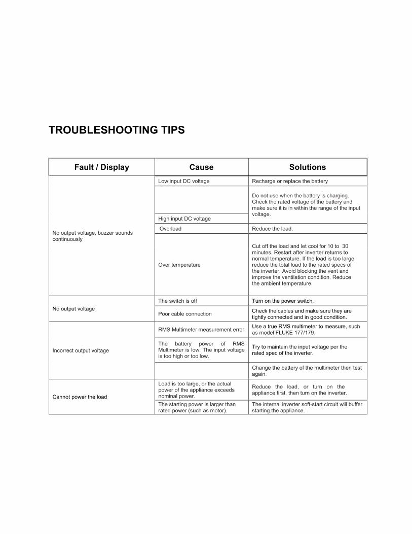
TROUBLESHOOTING TIPS
Fault / Display Cause Solutions
No output voltage, buzzer sounds continuously
Low input DC voltage Recharge or replace the battery
Do not use when the battery is charging. Check the rated voltage of the battery and make sure it is in within the range of the input voltage.
High input DC voltage
Overload Reduce the load.
Over temperature
Cut off the load and let cool for 10 to 30 minutes. Restart after inverter returns to normal temperature. If the load is too large, reduce the total load to the rated specs of the inverter. Avoid blocking the vent and improve the ventilation condition. Reduce the ambient temperature.
No output voltage The switch is off Turn on the power switch.
Poor cable connection Check the cables and make sure they are tightly connected and in good condition.
Incorrect output voltage
RMS Multimeter measurement error Use a true RMS multimeter to measure, such as model FLUKE 177/179.
The battery power of RMS Multimeter is low. The input voltage is too high or too low.
Try to maintain the input voltage per the rated spec of the inverter.
Change the battery of the multimeter then test again.
Cannot power the load
Load is too large, or the actual power of the appliance exceeds nominal power.
Reduce the load, or turn on the appliance first, then turn on the inverter.
The starting power is larger than rated power (such as motor).
The internal inverter soft-start circuit will buffer starting the appliance.

SPECIFICATIONS
MODEL NO PWRIX120012120SUL PWRIX200012120SUL DC Input Voltage 12V (10-16V) 12V (10-16V) Output Wave Form Pure Sine Wave THD
<3% Pure Sine Wave THD <3%
Output Power 1200W 2000W Surge Power Capacity 2400W for 40 milsec 4000W for 40 milsec Efficiency 90% 90% No Load Current 1.2 A switch on 1.2 A switch on Battery Low Alarm DC 9.8 +_ 0.3V DC 9.8 +_ 0.3V Battery Low Shutdown DC 9.5 +_ 0.5V DC 9.5 +_ 0.5V
Input Over Voltage Shutdown 16+_ 0.5 VDC 16+_ 0.5 VDC
Operating Temperature (Automatic Recovery/Shutdown)
32-113° F +_ 8° F 32-113° F +_ 8° F
Breaker 15 A resettable 15 A resettable
Transfer Switch- Automatic
Bypass 10 AMP <20msecs 25 AMP <20msecs
Over Temperature Protection 149° F +_ 8° F 149° F +_ 8° F
FAN Thermal Thermal
Marine Conformal coated to protect again moisture and corrosion
Conformal coated to protect again moisture and corrosion
USB Output 5 VDC, Max 1A 5 VDC, Max 1A
Internal DC Input Fuse Must Be Fitted, Use 40A *4 Maximum
Must Be Fitted, Use 40A *4 Maximum
Remote Switch Port YES YES
Recommended Cable Size 6 AWG or larger 2 AWG or larger
Mounting Hole Location 3 5/8” hole to hole on width side
11 3/8” center hole to center hole on length side
Power Switch ON/OFF Control ON/OFF Control
Cigarette Lighter Cable NO NO Dimensions (LxWxH) 15.5” x 10” x 3.5” 21.5” x 9.5” x 3.5” Net Weight 10.4 lb 14.4 lb

WARRANTY
This product is designed using the most modern digital technology and under very strict quality control and testing guidelines. If, however, you feel this product is not performing as it should, please contact us: [email protected] or (775)359-6703.
We will do our best to resolve your concerns. If the product needs repair or replacement, make sure to keep your receipt/invoice, as that will need to be sent back along with the package and RMA# prepaid to AIMS. You have a full 2 year warranty from date of purchase.
This warranty is valid worldwide with the exception that freight and duty charges incurred outside the contiguous 48 United States will be prepaid by customer.
Except as noted above, AIMS Power makes no warranty of any kind, express or implied, includingwithout limitation the implied warranties of merchantability and fitness for a particular purpose. In no event shall AIMS Pwer be liable for indirect, special or consequential damages. This warranty onlyapplies to AIMS Power branded products. All other name brand products are warranted by and according to their respective manufacturer. Please do not attempt to return non-AIMS Power branded products to AIMS Power.
The following situations will void warranty: 1. The box is distorted, damaged or changed, and interior parts damaged because of an
exterior hit or drop not reported at time of delivery.2. Connect the DC power incorrectly reversing the polarity.3. Dismantled or repaired the unit by an unauthorized person.4. The unit was damaged by incorrect installation or operating method.
For additional products, please visit our web site: www.aimscorp.net
-Modified sine wave inverters
-Pure sine wave inverters
-Low frequency inverters
-Solar charge controllers
-Inverter chargers
-Converters DC-DC
-Converters/battery chargers
-Custom cut cables
-Batteries
-Solar panels & racks
To find out where to buy any of our products, you may also e-mail: [email protected] or call (775)359-6703.
03-17-2021