dc1460 service manual
TRANSCRIPT

DC-1460 S/M (MCA)
SERVICEMANUAL
Published in Apr. ’9819570762Revision 2
R
DC-1460
DC
-146
0

CAUTION: DOUBLE-POLE / NEUTRAL FUSING

ServiceManual
DC-1460

Safety precautions
R
This booklet provides safety warnings and precautions for our servicepersonnel to ensure the safety of their customers, their machines as wellas themselves during maintenance activities. Service personnel areadvised to read this booklet carefully to familiarize themselves with thewarnings and precautions described here before engaging inmaintenance activities.

Safety warnings and precautions
Various symbols are used to protect our service personnel andcustomers from physical danger and to prevent damage to theirproperty. These symbols are described below:
DANGER: High risk of serious bodily injury or death may result frominsufficient attention to or incorrect compliance with warningmessages using this symbol.
WARNING: Serious bodily injury or death may result from insufficientattention to or incorrect compliance with warning messagesusing this symbol.
CAUTION: Bodily injury or damage to property may result frominsufficient attention to or incorrect compliance with warningmessages using this symbol.
SymbolsThe triangle ( ) symbol indicates a warning including dangerand caution. The specific point of attention is shown insidethe symbol.
General warning.
Warning of risk of electric shock.
Warning of high temperature.
indicates a prohibited action. The specific prohibition isshown inside the symbol.
General prohibited action.
Disassembly prohibited.

indicates that action is required. The specific actionrequired is shown inside the symbol.
General action required.
Remove the power plug from the wall outlet.
Always ground the copier.
1. Installation Precautions
WARNING
• Do not use a power supply with a voltage other than that specified.Avoid multiple connections to one outlet: they may cause fire or electricshock. When using an extension cable, always check that it isadequate for the rated current. ...............................................................
• Connect the ground wire to a suitable grounding point. Not groundingthe copier may cause fire or electric shock. Connecting the earth wireto an object not approved for the purpose may cause explosion orelectric shock. Never connect the ground cable to any of the following:gas pipes, lightning rods, ground cables for telephone lines and waterpipes or faucets not approved by the proper authorities. ........................
CAUTION:
• Do not place the copier on an infirm or angled surface: the copier maytip over, causing injury. ...........................................................................
• Do not install the copier in a humid or dusty place. This may cause fireor electric shock. .....................................................................................
• Do not install the copier near a radiator, heater, other heat source ornear flammable material. This may cause fire. .......................................
• Allow sufficient space around the copier to allow the ventilation grills tokeep the machine as cool as possible. Insufficient ventilation maycause heat buildup and poor copying performance. ...............................

• Always handle the machine by the correct locations when moving it. ....
• Always use anti-toppling and locking devices on copiers so equipped.Failure to do this may cause the copier to move unexpectedly ortopple, leading to injury. ..........................................................................
• Avoid inhaling toner or developer excessively. Protect the eyes. If toneror developer is accidentally ingested, drink a lot of water to dilute it inthe stomach and obtain medical attention immediately. If it gets into theeyes, rinse immediately with copious amounts of water and obtainmedical attention. ....................................................................................
• Advice customers that they must always follow the safety warnings andprecautions in the copier’s instruction handbook. ...................................
2. Precautions for Maintenance
WARNING
• Always remove the power plug from the wall outlet before startingmachine disassembly. ............................................................................
• Always follow the procedures for maintenance described in the servicemanual and other related brochures. ......................................................
• Under no circumstances attempt to bypass or disable safety featuresincluding safety mechanisms and protective circuits. .............................
• Always use parts having the correct specifications. ...............................
• Always use the thermostat or thermal fuse specified in the servicemanual or other related brochure when replacing them. Using a pieceof wire, for example, could lead to fire or other serious accident. ...........
• When the service manual or other serious brochure specifies adistance or gap for installation of a part, always use the correct scaleand measure carefully. ...........................................................................
• Always check that the copier is correctly connected to an outlet with aground connection. .................................................................................

• Check that the power cable covering is free of damage. Check that thepower plug is dust-free. If it is dirty, clean it to remove the risk of fire orelectric shock. .........................................................................................
• Never attempt to disassemble the optical unit in machines using lasers.Leaking laser light may damage eyesight. ..............................................
• Handle the charger sections with care. They are charged to highpotentials and may cause electric shock if handled improperly. .............
CAUTION
• Wear safe clothing. If wearing loose clothing or accessories such asties, make sure they are safely secured so they will not be caught inrotating sections. .....................................................................................
• Use utmost caution when working on a powered machine. Keep awayfrom chains and belts. .............................................................................
• Handle the fixing section with care to avoid burns as it can beextremely hot. .........................................................................................
• Check that the fixing unit thermistor, heat and press rollers are clean.Dirt on them can cause abnormally high temperatures. .........................
• Do not remove the ozone filter, if any, from the copier except forroutine replacement. ...............................................................................
• Do not pull on the AC power cord or connector wires on high-voltagecomponents when removing them; always hold the plug itself. ..............
• Do not route the power cable where it may be stood on or trapped. Ifnecessary, protect it with a cable cover or other appropriate item. ........
• Treat the ends of the wire carefully when installing a new charger wireto avoid electric leaks. ............................................................................
• Remove toner completely from electronic components. .........................
• Run wire harnesses carefully so that wires will not be trapped ordamaged. ................................................................................................

• After maintenance, always check that all the parts, screws, connectorsand wires that were removed, have been refitted correctly. Specialattention should be paid to any forgotten connector, trapped wire andmissing screws. ......................................................................................
• Check that all the caution labels that should be present on the machineaccording to the instruction handbook are clean and not peeling.Replace with new ones if necessary. ......................................................
• Handle greases and solvents with care by following the instructionsbelow: .....................................................................................................· Use only a small amount of solvent at a time, being careful not to
spill. Wipe spills off completely.· Ventilate the room well while using grease or solvents.· Allow applied solvents to evaporate completely before refitting the
covers or turning the main switch on.· Always wash hands afterwards.
• Never dispose of toner or toner bottles in fire. Toner may causesparks when exposed directly to fire in a furnace, etc. .........................
• Should smoke be seen coming from the copier, remove the powerplug from the wall outlet immediately. ..................................................
3. Miscellaneous
WARNING
• Never attempt to heat the drum or expose it to any organic solventssuch as alcohol, other than the specified refiner; it may generate toxicgas. .........................................................................................................

195
CONTENTS
I THEORY AND CONSTRUCTION SECTION1-1 Specifications
1-1-1 Specifications ................................................................................... 1-1-11-2 Handling Precautions
1-2-1 Drum ................................................................................................. 1-2-11-2-2 Developer and toner ......................................................................... 1-2-1
1-3 Mechanical Construction1-3-1 Part names and their functions ......................................................... 1-3-11-3-2 Machine cross section ...................................................................... 1-3-31-3-3 Drive system ..................................................................................... 1-3-41-3-4 Mechanical construction ................................................................... 1-3-5
II ELECTRICAL SECTION2-1 Electrical Parts Layout
2-1-1 Electrical parts layout ....................................................................... 2-1-12-2 Detection of Paper Misfeeds
2-2-1 Paper misfeed detection ................................................................... 2-2-12-2-2 Paper misfeed detection conditions ................................................. 2-2-2
2-3 Operation of the PCB2-3-1 Power source PCB ........................................................................... 2-3-12-3-2 Main PCB ......................................................................................... 2-3-22-3-3 AVR PCB .......................................................................................... 2-3-32-3-4 Operation unit PCB .......................................................................... 2-3-4
III SET UP AND ADJUSTMENT SECTION3-1 Installation
3-1-1 Unpacking and installation ............................................................... 3-1-13-1-2 Setting initial copy modes ............................................................... 3-1-103-1-3 Installing the dehumidifier heater (optional,
120 V specifications only) ............................................................... 3-1-113-1-4 Installing the flicker resistor (optional, 240 V/50 Hz
specifications only) ......................................................................... 3-1-133-2 Simulation
3-2-1 Simulations ....................................................................................... 3-2-13-3 Assembly and Disassembly
3-3-1 Precautions for assembly and disassembly ..................................... 3-3-13-3-2 Paper feed section ........................................................................... 3-3-23-3-3 Main charging section .................................................................... 3-3-133-3-4 Exposure section ............................................................................ 3-3-163-3-5 Drum section (metric specification only) ......................................... 3-3-503-3-6 Developing section (metric specification only) ............................... 3-3-533-3-7 Transfer section .............................................................................. 3-3-553-3-8 Cleaning section (metric specification only) ................................... 3-3-593-3-9 Fixing section ................................................................................. 3-3-62
195-1

3-4 PCB Initial Setting3-4-1 Replacing the main PCB .................................................................. 3-4-13-4-2 Adjustment-free variable resistors (VR) ........................................... 3-4-3
3-5 Self-diagnostics3-5-1 Self diagnostic function .................................................................... 3-5-1
3-6 Troubleshooting3-6-1 Image formation problems ................................................................ 3-6-13-6-2 Paper misfeed ................................................................................ 3-6-153-6-3 PCB terminal voltages .................................................................... 3-6-173-6-4 Electrical problems ......................................................................... 3-6-253-6-5 Mechanical problems ..................................................................... 3-6-31
3-7 AppendixesTiming chart No. 1 ...................................................................................... 3-7-1Timing chart No. 2 ...................................................................................... 3-7-2Timing chart No. 3 ...................................................................................... 3-7-3Power source PCB ..................................................................................... 3-7-4AVR PCB .................................................................................................... 3-7-5Operation unit PCB ..................................................................................... 3-7-6Main PCB ................................................................................................... 3-7-7Connection diagram ................................................................................... 3-7-8Wiring diagram ........................................................................................... 3-7-9
195-1

DC-1460 S/M (MCA)
THEORY ANDCONSTRUCTION
SECTION
I
I The
ory a
nd C
onst
ruct
ion S
ectio
n

195
1-1 Specifications1-1-1 Specifications .................................................................................... 1-1-1

195
1-1-1
1-1-1 Specifications
Type ......................................... DesktopCopying system ....................... Dry, indirect electrostatic systemOriginals ................................... Sheets, books and 3-dimensional objects
Maximum size: Folio/81/2" × 14"Original feed system ................ FixedCopy paper .............................. Plain paper:
80 g/m2 (metric), 75 g/m2 (inch) for drawer feed60 - 120 g/m2 (metric), 75 g/m2 (inch) for bypass feedSpecial paper: OHP film, letterhead and colored paperNote: Use the bypass for special paper.
Copying sizes ........................... Maximum: Folio/81/2" × 14"Minimum: A6R/51/2" × 81/2"
Magnification ratios .................. 70 - 141%, 1% incrementsFixed ratios:Metric1:1 6 1.0%, 1:1.410, 1:0.700Inch1:1 6 1.0%, 1:1.290, 1:0.780
Copy speeds ............................ At 100% magnification:A4R/81/2" × 11": 14 copies/min.A5R/51/2" × 81/2": 14 copies/min.Folio/81/2" × 14": 12 copies/min.
First copy time .......................... 5.8 s or less (A4R/81/2" × 11", 100% magnification,manual exposure)
Warm-up time .......................... 30 s or less (room temperature 20°C/68°F, 65%RH)Paper feed system ................... Automatic feed from the paper drawer
Capacity: 250 sheets of 80 g/m2 (metric) or 75 g/m2
(inch)Manual feed from the bypass section1 sheet at a time
Multiple copying ....................... 1 - 99 copiesPhotoconductor ........................ OPC (drum diameter 30 mm)Charging system ...................... Single positive corona charging
(drum potential: 820 V DC)Exposure system ..................... Slit exposureLens ......................................... Fixed-focal lens, f: 190 mm, F: 7.2Light source ............................. Halogen lamp, 230 WDeveloping system ................... Dry, magnetic brush
Developer: 2-component, ferrite carrier and N27 T blacktonerToner density control: toner sensorToner replenishing: automatic from a toner cartridge
Transfer system ....................... Single positive corona charging, +4.8 kV DC (reference)Separation system ................... Curvature separation
+100 V–50 V

195
1-1-2
Fixing system ........................... Heat rollerHeat source: halogen heater (910 W with 120 V supply,1040 W with 240 V supply)Control temperature: 175°C/347°F (at normal ambienttemperature)Abnormally high temperature protection devices:135°C/275°F and 140°C/284°F thermostatsFixing pressure: 94 N
Charge erasing system ............ Exposure by cleaning lampCleaning system ...................... Cleaning bladeFunctions ................................. ( 1 ) Self-diagnostics
( 2 ) Simulation( 3 ) Auto clear (30 - 270 s, in intervals of 30 s)( 4 ) Auto start( 5 ) Auto shutoff (15 - 240 min., in intervals of 15 min.)( 6 ) Auto preheat/energy saving (5 - 45 min., in
intervals of 5 min.)( 7 ) Exposure adjustment( 8 ) Auto exposure( 9 ) Photo mode(10) Manual magnification selection(11) Fixed magnification(12) User exposure control(13) Paper empty detection(14) Toner empty detection(15) Paper jam detection(16) Copy number setting(17) Total counter
Power source ........................... 120 V AC, 60 Hz, max. 10.2 A220 - 240 V AC, 50/60 Hz, 2.4 A (average)
Rated power consumption ....... 1361 W (220 - 240 V)1195 W (120 V)
Dimensions .............................. 515 (W) × 465 (D) × 320 (H) mm201/4" (W) × 185/16" (D) × 125/8" (H)
Weight ...................................... Approx. 22 kg/48.5 lbsFloor requirements ................... 515 (W) × 465 (D) mm
201/4" (W) × 185/16" (D)Accessories .............................. Copy tray

195
1-2 Handling Precautions1-2-1 Drum ................................................................................................. 1-2-11-2-2 Developer and toner .......................................................................... 1-2-1

195
1-2-1
1-2-1 Drum
Note the following when handling or storing the drum.• When removing the drum unit, never expose the drum surface to strong direct
light.• Keep the drum at an ambient temperature between –20°C/–4°F and 40°C/104°F
and at a relative humidity not higher than 85% RH. Avoid abrupt changes intemperature and humidity.
• Avoid exposure to any substance which is harmful to or may affect the quality ofthe drum.
• Do not touch the drum surface with any object. Should it be touched by hands orstained with oil, clean it.
• If the machine is left open for more than 5 minutes for maintenance, remove thedrum and store it in the drum storage bag (Part No. 78369020).
1-2-2 Developer and toner
Store the developer and toner in a cool, dark place. Avoid direct light, high humidity andtemperature.

195
1-3 Mechanical Construction1-3-1 Part names and their functions ......................................................... 1-3-11-3-2 Machine cross section ....................................................................... 1-3-31-3-3 Drive system ..................................................................................... 1-3-41-3-4 Mechanical construction .................................................................... 1-3-5
( 1 ) Paper feed section .................................................................... 1-3-5(1-1) Paper feed from the paper drawer .................................... 1-3-7(1-2) Paper feed from the bypass slot ....................................... 1-3-8
( 2 ) Main charging section ............................................................... 1-3-9( 3 ) Exposure section ..................................................................... 1-3-12( 4 ) Developing section .................................................................. 1-3-18( 5 ) Transfer and separation section .............................................. 1-3-26( 6 ) Cleaning section ...................................................................... 1-3-29( 7 ) Charge erasing section ........................................................... 1-3-30( 8 ) Fixing and eject section ........................................................... 1-3-32

AA A
A
AA A
A
E
E E
E
E
E E
E
EA
EA
195 S/M(1-3-1)
195
1-3-1
1-3-1 Part names and their functions
Figure 1-3-1
1 Original holder2 Contact glass3 Original size indicator4 Operation panel5 Drum unit6 Developing unit7 Developing unit release lever8 Toner cartridge
9 Front cover0 Paper drawer! Main switch@ Grips# Width guide$ Length guide% Copy tray^ Auxiliary tray
& Bypass section* Insertion guides( Release unit) Release unit button⁄ Eject section cover
1
2
@
!
^
4
%
3
5
6
8
7
9
⁄
(
$
#
0
)
&
(
*
AA A A
A
AA A A
A
E
E E E
E
E
E E E
E
195 S/M(1-3-1)
195
1-3-2
Metric
Inch
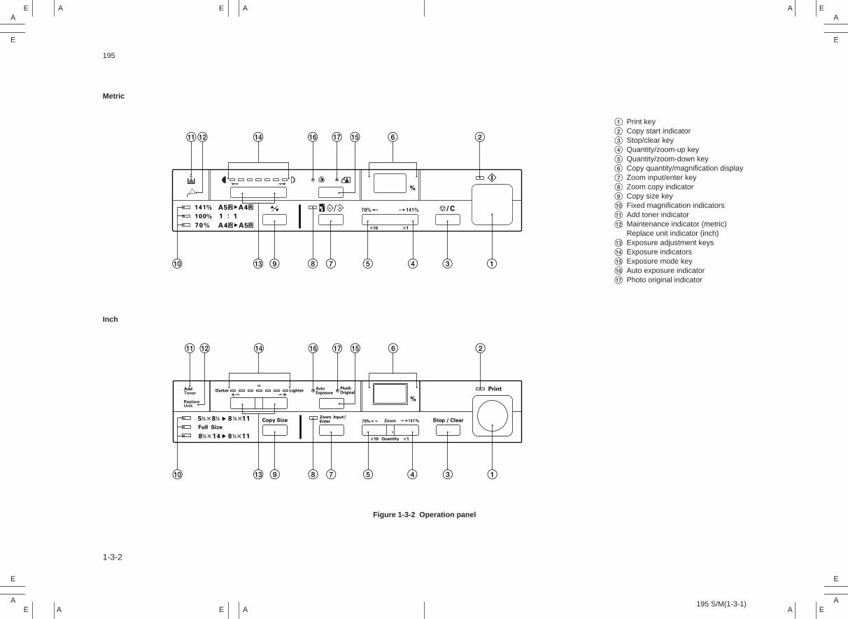
Figure 1-3-2 Operation panel
1 Print key2 Copy start indicator3 Stop/clear key4 Quantity/zoom-up key5 Quantity/zoom-down key6 Copy quantity/magnification display7 Zoom input/enter key8 Zoom copy indicator9 Copy size key0 Fixed magnification indicators! Add toner indicator@ Maintenance indicator (metric)
Replace unit indicator (inch)# Exposure adjustment keys$ Exposure indicators% Exposure mode key^ Auto exposure indicator& Photo original indicator
!
0 # 9 8 7 5 4 3 1
@ $ ^ & % 6 2
! @ $ ^ & % 6 2
1345789#0

195
1-3-3
1-3-2 Machine cross section
1
5
8
36 7
4
2
Figure 1-3-3 Machine cross section
1 Paper feed section (page 1-3-5)2 Main charging section (page 1-3-9)3 Exposure section (page 1-3-12)4 Developing section (page 1-3-18)
5 Transfer and separation section(page 1-3-26)
6 Cleaning section (page 1-3-29)7 Charge erasing section (page 1-3-30)8 Fixing and eject section (page 1-3-32)

195
1-3-4
1-3-3 Drive system
2
7
890!@
#
$%
^&*(
)‚‡Œ ⁄
612
2
„ · °fi
fl ›‹
¤
2 3
25
4
2
As viewed from machine rear
Figure 1-3-4 Drive system
1 Scanner wire2 Scanner wire pulley3 Mirror motor gear4 Scanner drive gear B5 Scanner wire drum B6 Scanner motor gear7 Scanner drive gear 648 Scanner wire drum A9 Eject roller gear0 Idle gear 20! Fixing gear 32@ Gear 27/38# Gear 41/56$ Gear 30/35% Gear 28^ Gear 33
& Feed gear 16* Gear 35( Paper feed clutch gear) Registration gear 14⁄ Gear 20/43¤ Drive motor gear‹ Gear 26/54› Drum drive gearfi Gear 38/43fl Developing drive gear‡ Gear 30° Toner cartridge drive gear· Toner cartridge drive gear‚ Toner cartridge idle gearŒ Toner cartridge idle gear„ Toner feed motor gear

195
1-3-5
1-3-4 Mechanical construction( 1 ) Paper feed section
7
5 3 2 1
4
#
69
%
!0
$ 8@
Figure 1-3-5 Paper feed section
1 Drawer bottom plate2 Drawer spring3 Front and rear drawer claws4 Paper feed pulleys A and B5 Feed roller guide6 Feed roller7 Bypass guide8 Feed pulley
9 Right registration roller0 Left registration roller! Upper pre-transfer guide@ Pre-transfer guide# Paper feed clutch (PFCL)$ Registration switch (RSW)% Registration clutch (RCL)

195
1-3-6
The paper feed section consists of the primary feed and secondary feed subsections.Primary feed conveys paper from the paper drawer or the bypass slot to the right andleft registration rollers, at which point secondary paper feed takes place and the papertravels to the transfer section in sync with the exposure timing.
MPCB
RSWCN7-5
RCL
PFCLCN7-6
CN7-7
Figure 1-3-6 Paper feed section block diagram

195
1-3-7
(1-1) Paper feed from the paper drawerThe paper drawer consists of the drawer bottom plate, drawer springs and othercomponents and can hold up to 250 sheets of copy paper.Paper is fed out of the drawer by the rotation of paper feed pulleys A and B.
600 ms
330 ms
246 P *1
A B C D
HPSW
SM
PFCL
RCL
RSW
200 ms
Print key
Auto exposure mode, A4R/81/2" × 14" copy paper, magnification ratio 100%*1 Varies depending on the setting by simulation 58.
Timing chart 1-3-1 Paper feed from the paper drawer
A 200 ms after the print key has been pressed, the paper feed clutch (PFCL) turns onfor 600 ms, rotating paper feed pulleys A and B to perform primary feed. Then thepaper is fed to the right and left registration rollers by the rotation of the feed roller.
B The leading edge of the paper turns the registration switch (RSW) on.C 246 pulses after the scanner has started scanning, the registration clutch (RCL)
turns on and the right registration roller conveys the paper to start secondary feed.D 330 ms after the trailing edge of the paper has turned the registration switch (RSW)
off, the registration clutch (RCL) turns off to complete secondary paper feed.

195
1-3-8
(1-2) Paper feed from the bypass slotThe bypass slot can hold one sheet of paper at one time.Copying starts when the paper turns the registration switch (RSW) on and the paper isconveyed to the secondary paper feed section by the feed roller.
RSW
246 P *1
200 ms
330 ms
HPSW
SM
RCL
DM
A B C
Cop
ying
sta
rt
FWD REV
Manual exposure mode, A4R/81/2" × 14" copy paper, magnification ratio 70%*1 Varies depending on the setting by simulation 58.
Timing chart 1-3-2 Paper feed from the bypass slot
A 200 ms after the leading edge of the paper has turned the registration switch (RSW)on, the drive motor (DM) turns on and the feed roller feeds the paper to start primarypaper feed where the paper is fed to the right and left registration rollers.
B 246 pulses after the scanner motor (SM) has started rotating forward, the registrationclutch (RCL) turns on and the right registration roller conveys the paper to startsecondary paper feed.
C 330 ms after the trailing edge of the paper has turned the registration switch (RSW)off, the registration clutch (RCL) turns off to complete secondary paper feed.

195
1-3-9
( 2 ) Main charging sectionThe main charging section consists of the drum and main charger. The drum iselectrically charged uniformly by means of a grid to form a latent image on the surface.
Main charger
Tungsten wire
Main charger grid
Figure 1-3-7 Main charging section

195
1-3-10
12
3
4
5
Figure 1-3-8 Main charger
MPCB
CN1-6
CN1-5
CN1-4
CN1-3
CN1-1
CN8-2
CN8-3
CN8-4
CN8-5
CN8-7
HV ALM
PHOTO REM
HV REM
DB REM
HVTPCB
MC
Grid
Drum
24 V DC
Figure 1-3-9 Main charging section block diagram
1 Main charger rear lid2 Charger spring3 Charger wire4 Main charger front lid5 Charger wire retainer pin

195
1-3-11
A B C
SM
DM
HV REM
200 ms
50 ms 384 ms
Print key
FWD REV
Manual exposure mode, A4R/81/2" × 14" copy paper, paper feed from the paper drawer
Timing chart 1-3-3 Main charging
A 200 ms after the print key has been pressed, the drive motor (DM) starts to rotate.B 50 ms after the drive motor (DM) has started to rotate, main charging (HV REM)
starts.C 384 ms after the scanner motor (SM) has stopped rotating forward, main charging
(HV REM) ends.

195
1-3-12
( 3 ) Exposure section
&
$
)
87@# 9
014
5
3 2 !
^(*
%
6
Figure 1-3-10 Exposure section
1 Mirror 12 Mirror 23 Mirror 34 Mirror 45 Mirror 56 Mirror 67 Halogen lamp (HL)8 Optical section thermostat
(TH3)9 Lens0 Light source unit 1
! Light source unit 2@ Main reflector# Auxiliary reflector$ Scanner motor (SM)% Optical section fan motor (OPFM)^ AE sensor (AES)& Home position switch (HPSW)* Lens home position switch (LHPSW)( Mirror home position switch (MHPSW)) Dust filter

195
1-3-13
This copier employs a slit exposure system with a fixed original table, and a halogenlamp (HL) as the light source.The optical section consists of light source units 1 and 2. Light source unit 1 carries thehalogen lamp and the main and auxiliary reflectors. Each unit travels from one side ofthe machine to the other along scanner rails at machine front and rear. When anenlargement or a reduction ratio is selected, the scanning speeds of the two light sourceunits and the positions of the lens and mirrors 2 and 3 are changed, altering thedistance between the original and the drum.A cooling fan is installed to exhaust heat generated by the halogen lamp. If anabnormally high temperature is detected around light source unit 1, the optical sectionthermostat (TH3) shuts off the supply to the halogen lamp.
SM
HL
CO
NT
LMLHPSW
AVRPCB
MPCB
HLHPSW AES
TH3 CN2-1
CN2-3
CN
4-5
CN
7-10
CN
12-9
CN
11-1
–C
N11
-5
CN
9-1
–C
N9-
5
CN
12-5
CN
10-2
MMMHPSW
CN
12-3
CN
11-6
–C
N11
-10
Original
Figure 1-3-11 Exposure section block diagram

195
1-3-14
A B C F GD E
200 ms
350 ms
910 P
100 ms
55 ms
2358 P5 P 5 P
65 ms
HPSW
SM
HL
Print key
FWD REV FWD REV
Auto exposure mode, A4R/81/2" × 14" original
Pre
scan
sta
rt
Sca
n st
art
Sca
nner
ret
urn
star
t
Timing chart 1-3-4 Scanner travel
A 200 ms after the print key has been pressed, the halogen lamp (HL) lights at theintensity for prescan.
B 350 ms after the halogen lamp (HL) has turned on, the scanner motor (SM) rotatesforward for prescan.
C After rotating forward for 910 pulses, the scanner motor (SM) pauses for 100 ms. Itthen reverses to return the scanner to the home position.
D 5 pulses after the home position switch (HPSW) has been turned on, the scannermotor (SM) turns off and the scanner stops.
E 55 ms after the scanner motor (SM) has turned off, it rotates forward again forscanning.
F After rotating forward for 2358 pulses, the scanner motor (SM) pauses. At the sametime, the halogen lamp (HL) turns off. 65 ms later, the scanner motor (SM) reversesto return the scanner to the home position.
G 5 pulses after the home position switch (HPSW) has been turned on, the scannermotor (SM) turns off and the scanner stops.

195
1-3-15
Exposure control for manual exposure and photo modes
The halogen lamp light intensity for manual exposure and photo modes is calculatedfrom the data obtained by running simulation 24. The number of exposure stepsdepends on the setting in simulation 96-1: 7 or 13 steps when set to “NORMAL MODE”and 19 or 25 steps when set to “SPECIAL AREA”. The exposure scale is wider forSPECIAL AREA than for NORMAL MODE.
0–6–6
+1+1
+2+2
+3+3
+4+4
+5+5
+6+6
–5–5
–4–4
–3–3
–2–2
–1 1 2 3 4 5 6 71 2 3 5 7 9 11 13–1 4 6 8 10 12
Light intensity value
Exposure scale (Exp.)
19 steps25 steps
: Exposure width for NORMAL MODE (7 or 13 steps)
Figure 1-3-12 Exposure gradient setting for SPECIAL AREA
•Exposure control for manual exposure modeThe gradient is determined from the halogen lamp intensity values for Exp. 1, Exp. 4 or7 and Exp. +2 set in simulation 24.The exposure control between Exp. +2 and Exp. +6 is based on the gradient of the lightintensity value between Exp. 4 or 7 and Exp. +2.The gradient of the light intensity value between Exp. –6 and Exp. 1 is 2 per step.•Exposure control for photo modeThe exposure for photo mode is controlled by setting the drum potential below that formanual exposure mode.

195
1-3-16
Exposure control for auto exposure mode
In auto exposure mode, the halogen lamp lights at the intensity set by simulation 28-1 toperform prescan. The exposure level to copy that particular original is determined byusing the value read in by the AE sensor.
100 mm
148 mm
AE detection (prescan)
Scannermovement
Original leading edge
Exposure Original leading edge
Original
Detection width
Figure 1-3-13 AE sensor detection width
0 NPTC NTC
AE sensor read-in value
Halogen lamp voltage
Manual-mode Exp. +2
Manual-mode Exp. 4 or 7
Figure 1-3-14 Exposure control for auto exposure mode
The halogen lamp voltage is controlled so that the lamp lights at the intensity formanual-mode Exp. 4 or 7 when the AE sensor read-in value is the NTC level and at theintensity for manual-mode Exp. +2 when the read-in value is the NPTC level whensetting auto exposure values in simulation 28-2 and -3.For read-in values below the NPTC level of simulation 28-3, the halogen lamp voltage iskept at a constant level so that the halogen lamp lights at the intensity for manual-modeExp. +2. For read-in values above the NTC level of simulation 28-2, the halogen lampvoltage is kept at a constant level so that the halogen lamp lights at the intensity formanual-mode Exp. 4 or 7.

195
1-3-17
Light intensity correction for enlargement and reduction modes
The halogen lamp light intensity for enlargement and reduction modes is determined bythe value for copying at 100% magnification and the correction values set by simulation29.
70 100 141
Sim. 29-2(70%)
0
Sim. 29-1(141%)
Light intensity correction value
Magnification ratio (%)
Figure 1-3-15 Correction of light intensity for enlargement and reduction modes
The correction values set by simulation 29 for reduction (70%) and enlargement (141%)copying are linked by a straight line through the value for 100% magnification, and thelight intensity is corrected for individual magnification ratios according to the gradients.The gradients vary depending on the setting values in simulation 29.The prescan light intensity for enlargement and reduction copying is increased by 0.1 asthe magnification ratio changes by 1%. For copying at 70% the prescan light intensity isthe 100% level plus 3; for 141%, the 100% level plus 4.1.

195
1-3-18
( 4 ) Developing sectionThe developing section consists of the developing unit and toner cartridge.
Developing unit
Toner cartridge
Figure 1-3-16 Developing section
The developing unit consists of the developing roller where a magnetic brush is formed,doctor blade and the developing spirals that agitate the developer.Toner in the toner cartridge is mixed with residual toner recovered from the cleaningsection, and the mixture is conveyed to the developing unit.

195
1-3-19
Cleaning spiral
Developing unit
Toner cartridge
Toner cartridge paddle
Toner cartridge spiral
Toner recycling spiralToner flow
Figure 1-3-17 Toner recycling

195
1-3-20
Formation of the magnetic brush
The developing roller consists of a magnet roller with five poles and a sleeve roller.Rotation of the sleeve roller around the magnet roller entrains developer, which in turnforms a magnetic brush at pole N1 on the magnet roller. The height of the magneticbrush is regulated by the doctor blade; the developing result is affected by the positionsof the poles on the magnet roller and the position of the doctor blade.The developing bias voltage generated by the high-voltage transformer PCB (HVTPCB)is applied to the developing roller to provide image contrast.
3
5
4
12
6
A
Figure 1-3-18 Forming the magnetic brush
S1
75˚
80˚
84˚
67˚
N1
S2N3
N2
Magnetic poles on the magnet roller
N1: 850 × 10–4 ± 50 × 10–4 TN2: 500 × 10–4 ± 50 × 10–4 TN3: 450 × 10–4 ± 50 × 10–4 TS1: 880 × 10–4 ± 50 × 10–4 TS2: 900 × 10–4 ± 50 × 10–4 T
A: distance between the doctor bladeand developing roller: 0.525 ± 0.025 mm
1 Developing unit housing2 Developing roller3 Toner sensor (TNS)
4 Doctor blade5 Right developing spiral6 Left developing spiral

195
1-3-21
CN2-1
CN2-2
CN6-7
CN6-8
CN8-5
TFM
TNS
TNS
TNS CONT
DB REM
MPCB
CN1-3
HVTPCB
Developing bias
Figure 1-3-19 Developing section block diagram
Toner density is detected by the toner sensor (TNS).The sensor section of the toner sensor detects the ratio of toner to carrier in thedeveloper near it and converts it into a voltage. As more toner is used, the ratio of tonerto carrier decreases, increasing the toner sensor output voltage.When the ratio drops below the specified value, the increase in toner sensor outputvoltage triggers toner replenishing. When toner is added and the ratio of toner to carrierreturns to normal, the toner sensor output voltage drops to the point where tonerreplenishing stops.

195-1
1-3-22
Toner density control
Toner density is controlled by switching the toner feed motor on and off, using as thereference the toner sensor output based on the toner sensor control voltage set whensimulation 60 was executed while the developer was first supplied. The toner sensoroutput is also used to detect an empty toner cartridge.
A B C D
E
Toner sensor output voltage (V)
AP detection level(3.21)
AP reset level(3.00)
Toner emptyend level (2.75)
Toner feed motor onlevel (2.05)
Toner feed motor offlevel (2.00)
“AP” blinks on the copy quantity/magnification display.
Max. 2 min.
Copy operation
Forced feed (continuously on)Intermittent feed (0.2 s on/1.0 s off)
Forced toner feed
Figure 1-3-20 Toner density control
A When the toner sensor output voltage exceeds the toner feed motor on level, thetoner feed motor intermittent feed (0.2 s on/1.0 s off) operation is carried out to feedthe toner.
B When the toner is fed and the toner sensor output voltage falls below the toner feedmotor off level, the intermittent feed operation is stopped.
C When the toner in the toner cartridge runs low and, even though the tonerintermittent feed operation is continued, the toner sensor output voltage rises abovethe AP detection level, “AP” blinks on the copy quantity/magnification display and thetoner feed motor forced feed (continuously on) operation starts.
D If the toner sensor output voltage falls to the AP reset level within the toner feedmotor forced feed operation time (2 minutes max.), the copier returns to the readystate and continues the intermittent feed operation.
E If the toner sensor output voltage does not fall to the AP reset level within 2 minutesafter it has started to fall below the AP detection level, the add toner indicator lights.

195
1-3-23
GF
Toner sensor output voltage (V)
AP detection level (3.21)
Toner emptyend level (2.75)
Toner feed motor onlevel (2.05)
Toner feed motor offlevel (2.00)
Toner cartridge replacement
Max. 3'19"
Forced toner feed
If forced feed does not lower the level, the add toner indicator stays lit.
The add toner indicatorturns off and intermittentfeed continues(2 minutesmax.) until the toner feedmotor off level is reached.
Copy operation
Figure 1-3-21
F After the toner cartridge is replaced, “AP” blinks and the forced feed operation(continuously on) is started by turning the safety switch off and on. During forcedfeed, the toner is fed and when the toner sensor output voltage reaches the tonerempty end level, “AP” on the copy quantity/magnification display goes out and thecopier enters the ready state. Further intermittent feed operation is carried out for upto 2 minutes or until the toner sensor output voltage reaches the toner feed motor offlevel.
G If the toner sensor output voltage does not reach the toner empty end level within theforced feed operation time, the add toner indicator stays lit even after the end of theforced feed operation time.

195-1
1-3-24
Controlling the toner sensor output voltage
When initializing the toner control level in simulation 60, the toner sensor control voltage(TNS CONT) is set so that the toner sensor output voltage (TNS) is 1.60 V DC.The image density is subject to humidity changes and the developing unit drive time. Tomaintain the image density constant, the toner sensor output voltage (TNS) is correctedby the toner sensor control voltage (TNS CONT).
–1
–0.9
–0.8
–0.7
–0.6
–0.5
–0.4
–0.3
–0.2
–0.1
11.3981.397 35.849
1 1 0 - 350 min.2 350 - 700 min.3 700 - 1050 min.4 1050 - 1400 min.5 More than 1400 min.
A B
2
3
4
5
Developing unit drive time
Absolute humidity (g/m3)
Toner sensor control voltage correction value (V)
Figure 1-3-22 Correction based on the absolute humidity
A The toner sensor control voltage correction value is kept constant when the absolutehumidity is between 1.397 and 11.398 g/m3. The toner sensor control voltagecorrection value varies depending on the developing unit drive time (the total drivemotor on time since the main switch was last turned on).
B The toner sensor control voltage correction value changes so that it is -0.5 V whenthe absolute humidity is 35.849 g/m3 when the absolute humidity is between 11.398and 35.849 g/m3. The rate of change is constant and it varies depending on thedeveloping unit drive time (the total drive motor on time since the main switch waslast turned on).

195
1-3-25
[Computing the absolute humidity]The humidity sensor (HUMSENS) and external temperature thermistor (ETTH) arelocated on the humidity sensor PCB (HUMPCB). The humidity sensor (HUMSENS)converts the relative humidity detected by the humidity sensing element into a voltageand sends it to the main PCB (MPCB). The main PCB computes the absolute humiditybased on this HUMSENS signal and the temperature (ETTH signal) detected by theexternal temperature thermistor.
HUMPCB
MPCB
HUMSENS
3 HUMSENS
4
5
GND
CN4-5
CN4-4
CN4-3
CN4-2
CN4-1
1
2
ETTHETTH
GND
Humidity sensing element
5 V DC
Figure 1-3-23 Absolute humidity computation block diagram
1050
1559
2068
2577
3086
3595
45
40
35
30
25
20
15
10
5
0
100
80
60
40
20
(˚C)(˚F)
Abs
olut
e hu
mid
ity (
g/m
3 )
Temperature (˚C/˚F)
Rel
ativ
e hu
mid
ity (
%R
H)
Figure 1-3-24 Absolute humidity vs. relative humidity

195
1-3-26
( 5 ) Transfer and separation section
Post-transfer guide
Tungsten wire
Transfer charger
Figure 1-3-25 Transfer and separation section
The transfer and separation section consists of the transfer charger.In the transfer charger, a high voltage generated by the high-voltage transformer PCB(HVTPCB) is applied across both ends of the tungsten wire for transfer charging and thetoner image is transferred from the drum surface onto the paper.After transfer, paper is separated from the drum by curvature separation under its ownweight and by the post-transfer guide.

195
1-3-27
1
9
2
4
5
6
8
7
3
Figure 1-3-26 Transfer charger
HV ALM
HV
CN8-7
CN8-2
CN1-1
HV REMCN8-4 CN1-4
CN1-6
MPCB
HVTPCB
Drum
24 V DC
Figure 1-3-27 Transfer and separation section block diagram
1 Front transfer housing2 Rear transfer housing3 Transfer front lid4 Transfer rear lid5 Transfer charger shield
6 Pre-transfer guide7 Charger wire8 Charger spring9 Charger wire retainer pin

195
1-3-28
A B C
SM
DM
HV REM
200 ms
50 ms 384 ms
Print key
FWD REV
Manual exposure mode, A4R/81/2" × 14" copy paper, paper feed from the paper drawer
Timing chart 1-3-5 Transfer and separation
A 200 ms after the print key has been pressed, the drive motor (DM) starts to rotate.B 50 ms after the drive motor (DM) has started to rotate, transfer charging (HV REM)
starts.C 384 ms after the scanner motor (SM) has stopped rotating forward, transfer charging
(HV REM) ends.

195
1-3-29
( 6 ) Cleaning sectionThe cleaning section consists of the cleaning blade, which removes residual toner fromthe drum surface after transfer, and the cleaning spiral that carries the residual tonerback to the toner cartridge.
4
13
2
Figure 1-3-28 Cleaning section
1 Drum2 Cleaning blade
3 Lower cleaning blade4 Cleaning spiral

195
1-3-30
( 7 ) Charge erasing section
Cleaning lamp (CL)
Blank lamps (BL)
Figure 1-3-29 Charge erasing section
The charge erasing section consists of the blank lamps (BL) and the cleaning lamp(CL).The blank lamps (BL) are 28 LEDs. All the LEDs light to create leading edge and trailingedge blank cut margins. During exposure, the required number of the 28 blank lamps onboth sides are lit depending on the paper size and the magnification ratio, removingcharge from the sections of the copy where no image is to be formed.The cleaning lamp (CL) removes residual charge from the drum surface.
CN2-1–CN2-5
CN2-6,CN2-7
CN2-1–CN2-5
CN2-13,CN2-14
CN4-11
CN1-4,CN1-3
CN1-16–CN1-12
CN9-1CN9-2CN7-4
MPCB
CL
BL DIG 5, 6
BL SEG a–e
DIG 5, 6
SEG a–eBL
CLCL REM
OPCB
AVRPCB
24 V DC
Drum
Figure 1-3-30 Charge erasing section block diagram

195
1-3-31
RSW
ESW
SM
HV REM
DM
CL
BL
100 ms
285 ms127 P *1
200 ms
190 ms *2
BA C D E
Bypass feed, manual exposure mode, A4R/81/2" × 14" copy paper,magnification ratio 70%*1 Varies depending on the magnification ratio and the setting by simulation 54.*2 Varies depending on the setting by simulation 59.
Scan start
FWD REV
All on Side erasure All on
Timing chart 1-3-6 Charge erasing
A 200 ms after the registration switch (RSW) has been turned on by the paper insertedto the bypass, the drive motor (DM), the cleaning lamp (CL) and all the blank lamps(BL) turn on.
B 127 pulses after the scanner has started scanning, the required number of blanklamps (BL) light depending on the paper size and the magnification ratio, removingunnecessary charge in the non-image forming area.
C 190 ms after the trailing edge of the paper has turned the registration switch (RSW)off, all the blank lamps (BL) turn on.
D 285 ms after the main charging (HV REM) has completed, the blank lamps (BL) turnoff.
E 100 ms after the paper has been ejected and the eject switch (ESW) has beenturned off, the drive motor (DM) and the cleaning lamp (CL) turn off at the same time.
195-1
1-3-32
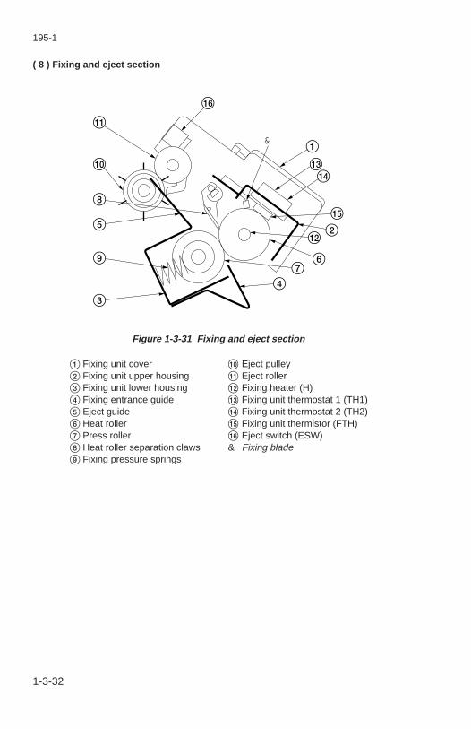
( 8 ) Fixing and eject section
1&
#$
%
2@
67
4
^
!
0
8
5
9
3
Figure 1-3-31 Fixing and eject section
1 Fixing unit cover2 Fixing unit upper housing3 Fixing unit lower housing4 Fixing entrance guide5 Eject guide6 Heat roller7 Press roller8 Heat roller separation claws9 Fixing pressure springs
0 Eject pulley! Eject roller@ Fixing heater (H)# Fixing unit thermostat 1 (TH1)$ Fixing unit thermostat 2 (TH2)% Fixing unit thermistor (FTH)^ Eject switch (ESW)& Fixing blade

195
1-3-33
The fixing and eject section consists of the parts shown in Figure 1-3-31. When thepaper reaches the fixing section after the transfer process, it passes through the gapbetween the press roller and heat roller, which is heated by the fixing heater (H).Pressure is applied by the fixing pressure springs so that toner on the paper is meltedand fused onto the paper.When the fixing process is completed, the paper is separated from the heat and pressrollers by the heat roller separation claws and is ejected out of the copier by the rotationof the eject pulley and eject roller.
H
TH2 TH1
FT
H
FT
H
H R
EM
MPCB
CN
7-11
CN
7-8
TB1
CN13-1
CN13-2
TB2
AVRPCB
CN
4-7
CN
4-4
FTH
H LIVE
H COMHeat roller
5 V DC
Figure 1-3-32 Fixing section block diagram
195
1-3-34
Heating the heat roller and detecting temperature
12
4
5
3
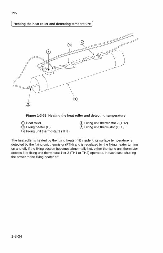
Figure 1-3-33 Heating the heat roller and detecting temperature
The heat roller is heated by the fixing heater (H) inside it; its surface temperature isdetected by the fixing unit thermistor (FTH) and is regulated by the fixing heater turningon and off. If the fixing section becomes abnormally hot, either the fixing unit thermistordetects it or fixing unit thermostat 1 or 2 (TH1 or TH2) operates, in each case shuttingthe power to the fixing heater off.
1 Heat roller2 Fixing heater (H)3 Fixing unit thermostat 1 (TH1)
4 Fixing unit thermostat 2 (TH2)5 Fixing unit thermistor (FTH)

195
1-3-35
Fixing temperature control
MSW
H
DM
CL
BL
FFM
Copy start indicator
200 ms
1 s
29 s
10 s
A B C DE F
Prim
ary
stab
iliza
tion
fixin
g te
mpe
ratu
re80
˚C/1
76˚F
Sec
onda
ry s
tabi
lizat
ion
fixin
g te
mpe
ratu
re18
5˚C
/365
˚F
Cop
ying
ena
bled
Prim
ary
stab
iliza
tion
fixin
g te
mpe
ratu
re17
5˚C
/347
˚F
Half speedFull speed
Timing chart 1-3-7 Fixing temperature control
A When the main switch (MSW) is turned on the fixing heater (H) turns on to heat theheat roller. The fixing fan motor (FFM) rotates at full speed for 1 s and then at halfspeed.
B 200 ms after the fixing temperature has reached 80°C/176°F, the drive motor (DM),cleaning lamp (CL) and blank lamps (BL) turn on to start primary stabilization.
C When the fixing temperature reaches 185°C/365°F, secondary stabilization isachieved. The fixing heater (H) is then turned on and off as required to keep thefixing temperature at 185°C/365°F.
D After secondary stabilization, copying is enabled and the copy start indicator lights ifthe time from the main switch (MSW) being turned on has reached the following:29 s if the temperature detected by the fixing unit thermistor is 10°C/50°F or aboveand the external temperature is 15°C/59°F or above when the main switch (MSW) isturned on;44 s if the temperature detected by the fixing unit thermistor is below 10°C/50°F orthe external temperature is below 15°C/59°F when the main switch (MSW) is turnedon;5 s if the temperature detected by the fixing unit thermistor is 80°C/176°F or abovewhen the main switch is turned on.
E After copying has been enabled, the fixing temperature falls to 175°C/347°F and thecopier enters the standby state. The fixing heater (H) is then turned on and off asrequired to keep the fixing temperature at 175°C/347°F.
F 10 s after the copy start indicator has lit, the drive motor (DM) turns off.

195-1
1-3-36
• Correcting the fixing temperature controlThe fixing temperature is changed according to the temperature detected by theexternal temperature thermistor (ETTH) on the humidity sensor PCB (HUMPCB).When the temperature detected by the thermistor is 32°C/89.6°F or above, the fixingtemperature is 175°C/347°F during standby and 180°C/356°F during copying.When the temperature detected by the thermistor is below 32°C/89.6°F, the fixingtemperature is 175°C/347°F during standby and 185°C/365°F during copying.
Paper separation
Paper is separated in the fixing section by the separation claws as shown in Figure 1-3-34.
Heat rollerseparation claws
Heat roller
Figure 1-3-34 Paper separation

DC-1460 S/M (MCA)
ELECTRICALSECTION
II
II Ele
ctric
al S
ectio
n

195
2-1 Electrical Parts Layout2-1-1 Electrical parts layout ........................................................................ 2-1-1

195
2-1-1
2-1-1 Electrical parts layout
5
1
3
2
6
4
Machine front Machine inside Machine rear
Figure 2-1-1 Layout of electrical parts: PCBs
1. Main PCB (MPCB) ....................................... Controls the other PCBs and electricalcomponents.
2. Power source PCB (PSPCB) ....................... Generates 24 V and 5 V DC; suppliesAC to the AVR PCB; contains thesafety switch and noise filter.
3. AVR PCB (AVRPCB) ................................... Controls the halogen lamp and fixingheater.
4. High-voltage transformer PCB (HVTPCB) ... Performs main charging; generatesdeveloping bias and high voltage fortransfer charging.
5. Humidity sensor PCB (HUMPCB)................ Detects absolute humidity. 6. Operation unit PCB (OPCB) ........................ Consists of operation keys and display
LEDs.

195
2-1-2
Machine front Machine inside Machine rear
2
1
11
12
913
3
14
5 78
10
4
6
Figure 2-1-2 Layout of electrical parts: switches and sensors
1. Main switch (MSW) ......................................Turns the AC power on and off. 2. Safety switch (SSW) ....................................Breaks the safety circuit when the front
cover or release unit is opened, andresets paper jam detection.
3. Registration switch (RSW) ...........................Controls the secondary paper feed starttiming.
4. Eject switch (ESW) ......................................Detects a paper jam in the fixingsection.
5. AE sensor (AES) ......................................... Detects the original density. 6. Home position switch (HPSW) ....................Detects the scanner in the home
position. 7. Mirror home position switch (MHPSW) ........ Detects mirrors 2 and 3 in the home
positions. 8. Lens home position switch (LHPSW) .......... Detects the lens in the home position. 9. Toner sensor (TNS) ..................................... Detects the toner density in the
developing section.10. Fixing unit thermistor (FTH) .........................Detects the heat roller temperature.11. Humidity sensor (HUMSENS) ..................... Detects the external humidity.12. External temperature thermistor (ETTH) ..... Detects the external temperature.13. Developing unit fuse* (DEVF) ......................Blows to differentiate between old and
new developing units.14. Toner cartridge detection switch ..................Detects the presence or absence of the
(TCDSW) toner cartridge.* Standard equipment only for 120 V, 220 V and 240 V specifications.
195-1

195
2-1-3
Machine front Machine inside Machine rear
2 7
3
1
9
85
10
64
Figure 2-1-3 Layout of electrical parts: motors and clutches
1. Drive motor (DM) ......................................... Drives the machine. 2. Scanner motor (SM) .................................... Drives the optical system. 3. Lens motor (LM) ..........................................Drives the lens. 4. Mirror motor (MM) ........................................ Drives mirrors 2 and 3. 5. Toner feed motor (TFM) .............................. Replenishes toner. 6. Optical section fan motor (OPFM) ............... Cools the optical system. 7. Fixing unit fan motor (FFM) ......................... Cools the fixing section. 8. Internal cooling fan motor (ICFM) ................ Cools the machine interior. 9. Paper feed clutch (PFCL) ............................ Performs primary paper feed from the
paper drawer.10. Registration clutch (RCL) ............................ Performs secondary paper feed.

195
2-1-4
Machine front Machine inside Machine rear
4
7 1
2 35, 6
8
9
Figure 2-1-4 Layout of electrical parts: other electrical parts
1. Halogen lamp (HL) ......................................Performs exposure. 2. Cleaning lamp (CL) ......................................Removes residual charge from the
drum surface. 3. Blank lamps (BL) ......................................... Remove charge from non-image
forming areas of the drum surface. 4. Fixing heater (H) ..........................................Heats the heat roller. 5. Fixing unit thermostat 1 (TH1) ..................... Prevents overheating in the fixing
section. 6. Fixing unit thermostat 2 (TH2) ..................... Prevents overheating in the fixing
section. 7. Optical section thermostat (TH3) ................. Prevents overheating in the optical
system. 8. Total counter (TC) ....................................... Displays the total number of copies
produced. 9. Dehumidifying heater (DH)* .........................Dehumidifies the machine interior. * Option available only for 120 V specifications.

195
2-2 Detection of Paper Misfeeds2-2-1 Paper misfeed detection ................................................................... 2-2-12-2-2 Paper misfeed detection conditions .................................................. 2-2-2

195
2-2-1
2-2-1 Paper misfeed detection
When a paper jam occurs, the copier immediately stops copying and the copy quantity/magnification display on the operation unit shows PF, J01, J02 or J03 indicating thelocation of the jam. The letter J and the number alternates on the display.To remove paper jammed in the copier, open the release unit, drawer or eject sectioncover.The paper misfeed detection can be reset by opening and closing the front cover orrelease unit to turn the safety switch off and back on.
Alternates.
PF: No paper feed (or, no paper present in the drawer)J01: paper jam in the fixing sectionJ02: paper jam in the eject sectionJ03: paper jam in the registration section
Figure 2-2-1 Misfeed location indication
PFCLRCL
RSW
ESW
Figure 2-2-2 Misfeed detection

195
2-2-2
2-2-2 Paper misfeed detection conditions
No paper feed (PF)
• The registration switch (RSW) does not turn on within 1100 ms after the paper feedclutch (PFCL) has turned on during drawer paper feed.
PFCL
1100 ms
On
Off
On
OffRSW
Timing chart 2-2-1
Paper jam in the registration section (J03)
• The registration switch (RSW) does not turn off within 4000 ms after the registrationclutch (RCL) has turned on.
RCL
4000 ms
On
Off
On
OffRSW
Timing chart 2-2-2
Paper jam in the fixing section (J01)
• The eject switch (ESW) does not turn on within 1668 ms after the registration clutch(RCL) has turned on.
RCL
1668 ms
On
Off
On
OffESW
Timing chart 2-2-3

195
2-2-3
Paper jam in the eject section (J02)
• The eject switch (ESW) does not turn off within 2000 ms after the registration switch(RSW) has turned off.
RSW
2000 ms
On
Off
On
OffESW
Timing chart 2-2-4

195
2-3 Operation of the PCB2-3-1 Power source PCB ............................................................................ 2-3-12-3-2 Main PCB .......................................................................................... 2-3-22-3-3 AVR PCB .......................................................................................... 2-3-32-3-4 Operation unit PCB ........................................................................... 2-3-4

195
2-3-1
2-3-1 Power source PCB
+
PSPCB
PC1PC2
Q1
C9
T1
MSW SSW
ACinput
Noise filter circuit 1 L1
Noise filtercircuit 2 L3
Rectify-ingcircuit DB1
Switchingcircuit IC1
Output feedbackcircuit
24 V DC smoothing/output circuit D101/C102
24 VDC output
5 V DC output
5 V DC smoothing/outputcircuit IC201
Figure 2-3-1 Power source PCB block diagram
The power source PCB (PSPCB) consists of the circuit blocks shown in Figure 2-3-1and converts the AC input into stable 5 V and 24 V DC outputs.Noise filter circuit 1 consists of choke coil L1, a resistor and capacitor. These attenuateexternal noise and prevent noise generated by the electrical components from escapingout of the copier via the AC line. Noise filter circuit 2 attenuates any external noise thathas passed through noise filter circuit 1 and prevents the switching noise generated inthe power source PCB from escaping out via the AC line. The AC input is full-waverectified by diode bridge DB1 and then smoothed by smoothing capacitor C9. Theswitching circuit turns FET Q1 on and off via switching control IC1, turning current to theprimary coil of switching transformer T1 on and off. The 24 V DC smoothing/outputcircuit converts the potential induced across the secondary coil of T1 into a stable 24 VDC output via diode D101 and smoothing capacitor C102. The 5 V DC smoothing/output circuit converts the potential induced across the other secondary coil of T1 into astable 5 V DC output via regulator IC201. Switching control IC1 regulates the 24 V DCsupply by controlling the switching operation of FET Q1 depending on the signal fedback by the output feedback circuit via photocoupler PC1. If an overvoltage occurs onthe 24 V or 5 V DC output, the output feedback circuit sends that information to switchcontrol IC1 via photocoupler PC2, inhibiting IC1.

195
2-3-2
2-3-2 Main PCB
HVTPCB
RSWESW
PFCLRCL
Scanning-relatedswitchesand sensors
OPCB
TNS
Driver ICIC17
EPROMIC15
CPUIC12OP
FM
MM
FFM
LM
SM
DM
CL
FTH
H
HLScanner motor drivecircuit IC11
MPCB AVRPCB
AVR circuit
HL REM
H REM
Shortedthermistordetectioncircuit
Reset IC IC1
Figure 2-3-2 Main PCB block diagram
The main PCB (MPCB) consists of the CPU and control circuits that regulate theelectrical components during the copying process.Based on the control programs in EPROM IC15, CPU IC12 controls the overall copiersystem: the drive motor, scanning-related motors, switches and sensors, toner sensor(TNS), clutches and switches in the paper feed, registration and eject sections; andsends out MC and TC remote signals to the high-voltage transformer PCB (HVTPCB).The halogen lamp (HL) and the fixing heater (H) are also controlled by the main PCBvia the AVR PCB (AVRPCB).

195
2-3-3
2-3-3 AVR PCB
Flickerresistor
Flicker REM
H REM
HL CONTH
HL
TRC1
PC3
TRC2
PC2
PC1
PWM signal/voltage converter circuit
Halogen lamp light intensity control IC (HIC)
TRC3
PC5
AVRPCB MPCB
AC input
Figure 2-3-3 AVR PCB block diagram
The AVR PCB (AVRPCB) consists of two major sections: the halogen lamp controlsection with the PWM signal/voltage converter circuit and halogen lamp light intensitycontrol IC (HIC), and the switching section with triacs TRC1, TRC2 and TRC3 that turnthe fixing heater (H), flicker resistor* and halogen lamp (HL) on and off.Control signal H REM from the main PCB turns photocoupler PC2 on when low. Thisapplies a trigger voltage to the gate of triac TRC2, causing it to conduct and allowcurrent to flow to the fixing heater (H) to turn it on. The flicker resistor* limits the surgegenerated by the fixing heater (H) being turned on. The Flicker REM signal from themain PCB turns photocoupler PC5 on when low. This applies a trigger voltage to thegate of triac TRC3, causing it to conduct and allow current to the flicker resistor tooperate it. The halogen lamp (HL) light intensity is controlled by control signal HL CONTfrom the main PCB. HL CONT is a PWM signal turned on and off at a duty ratio set bythe halogen lamp light intensity data. This signal is converted into a voltage by the PWMsignal/voltage converter circuit and is output to the halogen lamp light intensity controlIC (HIC). This adjusts the phase of the trigger which turns photocoupler PC3 on, basedon the halogen lamp light intensity data converted into a voltage, using an internal zero-crossing signal as a reference. The phase-shifted trigger applied to the gate of triacTRC1 changes the amount of current flowing to the halogen lamp (HL), regulating thehalogen lamp light intensity.* For 230 V specifications and optional for 240 V specifications.

195
2-3-4
2-3-4 Operation unit PCB
P G
S
24 V DC
Source driver
Sink driver
5 V DC
LEDsand 7-seg LEDs
Key switches
OPCB MPCB
KEY 0
DIG 5DIG 6
DIG 4DIG 3DIG 2DIG 1DIG 0
BL
SE
G a
BL
SE
G b
BL
SE
G c
BL
SE
G d
BL
SE
G e
BL
DIG
5B
L D
IG 6
SEG fSEG g
SEG eSEG dSEG cSEG bSEG a
KEY 1
Blank lamps
Figure 2-3-4 Operation unit PCB block diagram
The operation unit PCB (OPCB) consists of LEDs, 7-segment LEDs and key switchesarranged in matrix.To light an LED or 7-segment LED, the main PCB (MPCB) turns on one of the sourcedrivers for lines SEG a to SEG g to allow current to the line on which the LED or 7-segment LED to be lit is present. Scan signals which go low in sequence are constantlyoutput to the sink drivers for lines DIG 0 to DIG 5, so current flows through the LED forwhich the two signals are low simultaneously.The status of key switches is detected by return signals KEY 0 and KEY 1. When noneof the keys on the operation panel is pressed, each line of return signals KEY 0 andKEY 1 is pulled high to 5 V DC by the main PCB (MPCB). The main PCB (MPCB)outputs scan signals that go low in sequence to the sink drivers for lines DIG 0 to DIG 4,so when a key is pressed, the key switch conducts and the return signal goes low dueto the scan signal. The main PCB (MPCB) identifies the specific key by the location ofthe point where the line emitting the scan signal and the line with the low return signalmeet.The operation unit PCB (OPCB) also controls the blank lamps which are 28 LEDs. Tolight the blank lamps, the main PCB (MPCB) turns on the source drivers for lines BLSEG a to BL SEG e to allow current to the lines on which the blank lamps to be lit are

195
2-3-5
present. Scan signals which go low in sequence are constantly output to the sink driversfor lines BL DIG 5 and BL DIG 6, so current flows through the LEDs for which the bothsignals are low simultaneously.

DC-1460 S/M (MCA)
III S
et U
p an
d A
djus
tmen
t Sec
tion
III
SET UP ANDADJUSTMENT
SECTION

195
3-1 Installation3-1-1 Unpacking and installation ................................................................ 3-1-1
( 1 ) Installation environment ............................................................ 3-1-1( 2 ) Installation procedure ................................................................ 3-1-2
3-1-2 Setting initial copy modes ............................................................... 3-1-103-1-3 Installing the dehumidifier heater (optional, 120 V
specifications only) .......................................................................... 3-1-113-1-4 Installing the flicker resistor (optional, 240 V/50 Hz
specifications only) .......................................................................... 3-1-13
195-1

3-1-1
195
3-1-1 Unpacking and installation
( 1 ) Installation environment 1. Temperature and humidity: 10°C/50°F to 35°C/95°F, 15 - 85% RH 2. Power supply: 120 V AC, 12 A, 220 - 240 V AC, 8 A 3. Power source frequency: 50/60 Hz ± 0.3% 4. Installation location
• Avoid direct sunlight or bright lighting. Make sure that the photoconductor will notbe exposed to direct sunlight or other strong light when removing paper jams.
• Avoid extremes of temperature and humidity, abrupt ambient temperaturechanges, and hot or cold air directly hitting the machine.
• Avoid dust and vibration.• Choose a surface capable of supporting the weight of the machine.• Place the machine on a level surface (maximum allowable inclination: 1°).• Avoid airborne substances that may adversely affect the machine or degrade the
photoconductor, such as mercury, acidic and alkaline vapors, inorganic gases,NOx, SOx gases and chlorine-based organic solvents.
• Select a room with good ventilation. 5. Allow sufficient access for proper operation and maintenance of the machine.
Machine front: 1000 mm/393/8" Machine rear: 100 mm/315/16"Machine right: 100 mm/315/16" Machine left: 300 mm/1113/16"
ea
c
d
b
f
a: 515 mm/201/4" c: 320 mm/125/8" e: 780 mm/3011/16"b: 465 mm/185/16" d: 775 mm/301/2" f: 660 mm/26"
Figure 3-1-1 Installation dimensions

3-1-2
195
( 2 ) Installation procedure
Completion of machine installation.
Carry out initial developer setting.
Install a toner cartridge.
Install the copy tray.
Make test copies.
Remove the tapes.
Remove the pins.
Remove the developing unit spacer.
Remove the developing unit seal (inch specifications only).
Load developer (metric specifications only).
Start
Unpack. Apply fixing pressure.
Light source unit 2 pin
Lens unit pin
Copy tray
Light source unit 1 pins
Figure 3-1-2
195-1

3-1-3
195
36
7
0
4
!
5
9
$
@2
1
!
#
A
A
Figure 3-1-3 Unpacking
1 Bottom pads 8 Copier2 Top pads 9 Copy tray3 Outer case 0 Power cord4 Plastic sheet ! Tag5 Plastic bag @ Instruction handbook6 Bar code labels # Plastic bag7 Inner frame $ Developing unit spacer
Unpack.
195-1

3-1-4
195
1. Remove the tapes holding the original holder.
Tapes
Tapes
Figure 3-1-4
1. Remove the tapes holding the two light source unit 1 pins and one light sourceunit 2 pin on the machine right, and remove these pins.
Light source unit 1 pins
Light source unit 2 pin
Figure 3-1-5
Remove the tapes.
Remove the pins.
195-1

3-1-5
195
2. Open the front cover, and remove the tape holding the lens unit pin and thenthe pin.
Lens unit pin
Figure 3-1-6
1. Remove the tape and the developing unit spacer from the developing unit.
Developing unit spacer
Developing unit
Figure 3-1-6-1
Remove the developing unit spacer.
195-1

3-1-6
195
3-1-5-1
1. While holding the developing unit, peel off the developing unit seal.
Developing unit seal
Figure 3-1-7
Remove the developing unit seal (inch specifications only).
195-1

3-1-7
195
This page is intentionally left blank.

3-1-8
195
1. Unlock the developing unit release lever and take out the developing unit.Important : Place the developing unit on a level surface.
Developing unit
Figure 3-1-8
2. Remove the developing unit cover from the developing unit by pulling it in thedirection of the arrow (four screws).
Developing unit cover
Developing unit
Figure 3-1-9
Load developer (metric specifications only).
3-1-6
3-1-9
195
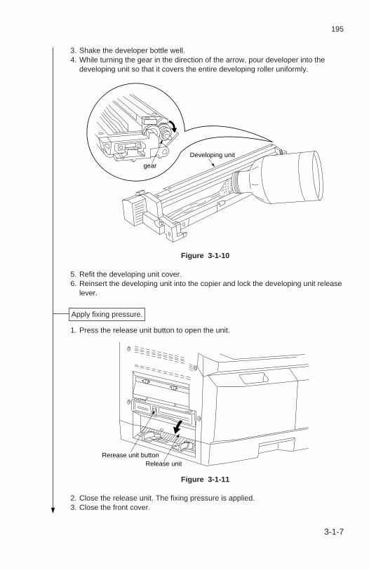
3. Shake the developer bottle well. 4. While turning the gear in the direction of the arrow, pour developer into the
developing unit so that it covers the entire developing roller uniformly.
Developing unit
gear
Figure 3-1-10
5. Refit the developing unit cover. 6. Reinsert the developing unit into the copier and lock the developing unit release
lever.
1. Press the release unit button to open the unit.
Rerease unit buttonRelease unit
Figure 3-1-11
2. Close the release unit. The fixing pressure is applied. 3. Close the front cover.
Apply fixing pressure.
3-1-7

3-1-10
195
• Inch specifications
1. Plug the power cord into the copier and the wall outlet. 2. Turn the main switch on. The copier starts its drive and automatically carries out
initial developer setting. It takes about 2 minutes. 3. Turn the main switch off and back on while pressing the print and stop/clear
keys. 4. Press the stop/clear key to enter simulation mode within 2 s after “ ” has been
displayed on the copy quantity/magnification display.
• Metric specifications
1. Plug the power cord into the copier and the wall outlet. 2. While pressing the print key and the stop/clear key at the same time, turn the
main switch on. 3. Within 2 s after the copy quantity/magnification display shows “ ”, press the
stop/clear key to enter simulation mode. 4. Enter 60 with the quantity/zoom-up or -down key and press the print key. 5. Press the print key. After about 2 minutes, the toner control voltage is
automatically set and the value is indicated as shown below: the integer isindicated by the fixed magnification indicators or auto exposure indicator, anddecimals are shown on the copy quantity/magnification display (See page 3-2-2).Example
If the value is 2.35 V
123
2.35 V
4
Figure 3-1-12
6. Press the stop/clear key.
Carry out initial developer setting.
3-1-8
195-1

3-1-11
195
3-1-8-1
1. Enter 93 with the quantity/zoom-up or -down keys and press the print key. 2. Change the setting with the quantity/zoom-up or down keys.
Setting0 12345
Metric, excluding Spain, Belgium, Peru, Australia and New ZealandInch, excluding the PhilippinesSpainBelgiumPeru, Australia and New ZealandThe Philippines
Contents
3. Press the print key. The new setting is stored. 4. Press the stop/clear key. 5. Enter 01 with the quantity/zoom-up or -down keys and press the print key. The
simulation mode is exited.
Setting the destination.
195-1

3-1-12
195
This page is intentionally left blank.

3-1-13
195
1. Open the front cover. 2. Shake the new toner cartridge well and insert it into the copier.
Toner cartridge
Figure 3-1-13
3. Close the front cover.
1. Install the copy tray to the eject section of the copier.
1. Place paper in the paper drawer and make test copies.
Install a toner cartridge.
Install the copy tray.
Make test copies.
Completion of machine installation.
3-1-9

3-1-14
195
3-1-2 Setting initial copy modes
Factory settings are as follows:
Selecting between auto preheat on/offSetting the presence of the flicker resistorSetting operation under the toner empty conditionSelecting between auto start on/offSetting the destinationSetting the memory switchSetting the maintenance methodSelecting between E2000-compliant function on/off
Factory settingOn
Not installed20 copies
OnMetric7 stepsUserNo
ContentsSim. No.8589919293969899
3-1-10
195-1

3-1-15
195
3-1-3 Installing the dehumidifier heater (optional, 120 Vspecifications only)
• Required partsDehumidifier heater (P/N 36727460)Heater primary wire (P/N 19560010)Binding taptight screw, M3 × 6 (P/N B3023060)
Procedure 1. Remove the right and rear covers. 2. Unplug all the connectors on the power source PCB and remove the PCB from the
copier (two screws).
Power source PCB
Figure 3-1-14
3. Fit the dehumidifier heater to the copier with the two M3 × 6 binding taptight screws.
Dehumidifier heater
Binding taptight screws, M3×6
Figure 3-1-15
3-1-11

3-1-16
195
4. Remove the copier primary wire from the AVR PCB and connect the heater primarywire in place of it.
AVR PCB
Heater primary wire
Figure 3-1-16
5. Plug the 2-pin connector of the heater primary wire into the dehumidifier heater.
2-pin connector
Dehumidifier heater
Heater primary wire
Figure 3-1-17
6. Refit all the removed parts.
3-1-12

3-1-17
195
3-1-13
3-1-4 Installing the flicker resistor (optional, 240 V/50 Hzspecifications only)
• Required partsResistor wire (P/N 19527230)Resistor, 10Ω 40 W (P/N 36727600)Resistor, 10Ω 40 W 157 (P/N 36727610)Wire saddle, WS-2NS (P/N M2109010)Binding S tight screw, M4 × 6 (P/N B3024060)
Procedure 1. Remove the right and rear covers. 2. Unplug all the connectors on the power source PCB and remove the power source
PCB from the copier (two screws).
Power source PCB
Figure 3-1-18
3. Connect the resistor wire to the 10Ω 40 W resistor and 10Ω 40 W 157 resistor.
ΩResistor, 10 40 W 157
Resistor wire
Resistor, 10 40 WΩ
Figure 3-1-19
195-1

3-1-18
195
3-1-14
4. Attach the 10Ω 40 W and 10Ω 40 W 157 resistors to the copier with one M4 × 6binding S tight screw each.
5. Attach the wire saddle WS-2NS to the copier and pass the resistor wire through it.
Resistor, 10 40 W 157Ω Resistor wire
Resistor, 10 40 WΩ
Binding S tight screws M4 6×
Wire saddle, WS-2NS
Figure 3-1-20
6. Pass the resistor wire through the cutout in the copier and connect the 4-pinconnector to CN3 on the AVR PCB.
AVR PCB
Resistor wire
4-pin connector CN3
Figure 3-1-21
7. Refit the removed parts. 8. Turn the main switch on and change the setting of simulation 89 to 1 (installed).
195-1

195
3-2 Simulation3-2-1 Simulations ........................................................................................ 3-2-1
( 1 ) Running a simulation ................................................................. 3-2-1( 2 ) Simulation list ............................................................................ 3-2-4( 3 ) Contents of simulations ............................................................. 3-2-5

3-2-1
195
3-2-1 SimulationsThe copier is equipped with a simulation function which can be used to check andadjust the operation of copier components.
( 1 ) Running a simulation
Start
End
While pressing the print key and stop/clear key at the same time, turn the main switch on.
Press the stop/clear key within 2 s.
Enter 01 with the quantity/zoom-up and -down keys and press the print key.
Enter the number of the simulation to be executed with the quanti-ty/zoom-up and -down keys*1.
Press the print key.
The simulation is run.*1 Press the quantity/zoom-up key
to change the 10s digit and the quantity/zoom-down key to change the 1s digit.
Press the stop/clear key.
No
Yes
Yes
No
Run again?
Run another simulation?
· · · · · · · Simulation mode is entered.
· · · · · · · A simulation is selected.
“ ” is shown on the copy quantity/magnification display.
· · · · · · · · · · · · · · · · · · · · · ·
“00” is shown on the copy quantity/magnification display.
· · · · · · · · · · · · · · · · · · · · · ·
The selected simulation number is shown on the copy quantity/magnification display.
· · · · · · · · · · · · · · · · · · · · · ·
· · · · · · · Simulation mode is exited.

3-2-2
195
• Indication of the set valuesWhen a set value includes decimals, it is indicated as shown below: the integer isshown by the fixed magnification indicators or auto exposure indicator, and decimalsare shown on the copy quantity/magnification display.
Example
If the value is 2.35 V
Metric
Inch
Figure 3-2-1
123
2.35 V
4
123
2.35 V
4

3-2-3
195
• Indication of the selected modeIn a simulation with multiple modes, one of the exposure indicators lights to show theselected mode. Use the exposure adjustment keys to change the modes.
Metric
Inch
Figure 3-2-2
Mode
Exposure adjustment keys
Mode
Exposure adjustment keys
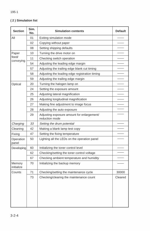
3-2-4
195
SectionSim.
Simulation contents DefaultNo.
( 2 ) Simulation list
All
Paperfeed/conveying
Optical
Charging
Cleaning
Fixing
Operationpanel
Developing
Memoryinitialize
Counts
01 Exiting simulation mode
02 Copying without paper
08 Setting shipping defaults
10 Turning the drive motor on
11 Checking switch operation
54 Adjusting the leading edge margin
57 Adjusting the trailing edge blank cut timing
58 Adjusting the leading edge registration timing
59 Adjusting the trailing edge margin
20 Turning the halogen lamp on
24 Setting the exposure amount
25 Adjusting lateral magnification
26 Adjusting longitudinal magnification
27 Making fine adjustment to image focus
28 Adjusting the auto exposure
29 Adjusting exposure amount for enlargement/reduction mode
33 Setting the drum potential
42 Making a blank lamp test copy
47 Setting the fixing temperature
50 Lighting all the LEDs on the operation panel
60 Initializing the toner control level
62 Checking/setting the toner control voltage
67 Checking ambient temperature and humidity
70 Initializing the backup memory
71 Checking/setting the maintenance cycle
73 Checking/clearing the maintenance count
30000
Cleared
195-1

3-2-5
195
SectionSim.
Simulation contents DefaultNo.
Copymodes
85 Selecting between auto preheat on/off
89 Setting the presence of the flicker resistor
91 Setting operation under the toner empty condition
92 Selecting between auto start on/off
93 Setting the destination
96 Setting the memory switch
98 Setting the maintenance method
99 Selecting between E2000-compliant function on/off
On
Not installed
20 copies
On
Metric
7 steps
User
No
195-1
3-2-4-1

3-2-6
195
This page is intentionally left blank.

195
Sim.No.
Description
01 Exiting simulation mode
DescriptionExits simulation mode and returns to normal mode.
PurposeUsed when ending simulation mode.
MethodPress the print key. The copier returns to normal mode.
02 Copying without paper
DescriptionMakes copies without feeding paper.
PurposeTo check general machine operation.
Method 1. Put a plain white A4 original in place.
2. Open the drawer.
3. Select copy modes and press the print key to start copying. The copieroperates according to the selected modes.
CompletionPress the stop/clear key. Copying operation stops.
08 Setting shipping defaults
DescriptionMoves the scanner to the shipping position.
PurposeTo be run before moving the machine.
MethodPress the print key.
Important: Since this simulation clears the maintenance count, runsimulation 73 and check it beforehand.
CompletionPress the stop/clear key.
(3) Contents of simulations
3-2-5

195
Sim.No.
Description
10 Turning the drive motor on
DescriptionOperates the drive motor.
PurposeTo check the drive system operation.
MethodPress the print key. The drive motor, cleaning lamp and developing bias areturned on, and the fixing unit fan motor rotates at full speed.
CompletionPress the stop/clear key. The fixing unit fan motor slows to half speed andthe other components are turned off.
11 Checking switch operation
DescriptionShows the status of the registration and eject switches.
PurposeTo check if the registration and eject switches are defective.
MethodTurn each switch on and off manually. The copy quantity/magnificationdisplay shows the status of the switch.
CompletionPress the stop/clear key.
On
01
10
Registration switch
Eject switch
Off
00
00
3-2-6

195
Sim.No.
Description
20 Turning the halogen lamp on
DescriptionLights the halogen lamp.
PurposeTo check the halogen lamp operation.
Method 1. Select an exposure level with the exposure adjustment keys.
2. Press the print key. The halogen lamp lights at the selected intensity for15 s.
CompletionPress the stop/clear key. The halogen lamp is turned off.
24 Setting the exposure amount
AdjustmentSee page 3-3-37.
25 Adjusting lateral magnification
AdjustmentSee page 3-3-45.
26 Adjusting longitudinal magnification
AdjustmentSee page 3-3-49.
27 Making fine adjustment to image focus
AdjustmentSee page 3-3-32.
28 Adjusting the auto exposure
AdjustmentSee page 3-3-41.
29 Adjusting exposure amount for enlargement/reduction mode
AdjustmentSee page 3-3-42.
3-2-7

195
Sim.No.
Description
33 Setting the drum potential
DescriptionSets the drum potential.
PurposeTo be run when adjusting the developing bias.
MethodPress the print key. The drum potential setting starts.
CompletionPress the stop/clear key.
42 Making a blank lamp test copy
DescriptionLights the blank lamps.
PurposeTo check blank lamp operation.
Method 1. Load a sheet of the maximum size.
2. Open the original holder.
3. Press the zoom input/enter key. Test copy mode is entered.
4. Press the print key. The blank lamps light in a preset order and thepattern shown below is printed to check operation.
Figure 3-2-3
CompletionPress the stop/clear key.
195-1
3-2-8

195
Sim.No.
Description
47 Setting the fixing temperature
DescriptionChanges the fixing heater control value to adjust the fixing temperature.
PurposeTo be run when a fixing problem occurs.
Setting 1. Select the mode to be set with the exposure adjustment keys. The
current setting for that mode is indicated by the combination of lightingof one of the fixed magnification indicators or the auto exposureindicator and the figures on the copy quantity/magnification display.
2. Change the setting with the quantity/zoom-up and -down keys.Changing the value by one changes the temperature by 0.6°C when thefixing temperature is 180°C and 0.3°C when it is 80°C.
3. Press the print key. The new setting is stored.
CompletionPress the stop/clear key.
50 Lighting all the LEDs on the operation panel
DescriptionLights all the LEDs on the operation panel.
PurposeTo check the operation of the LEDs on the operation panel.
MethodPress the print key. All the LEDs on the operation panel light.
CompletionPress the stop/clear key. The LEDs turn off.
Mode
1
2
3
4
5
Contents Setting range
1.70 to 4.45 V
3.41 to 4.45 V
3.41 to 4.45 V
3.41 to 4.45 V
0.39 to 4.45 V
Initial value
3.98 V (175°C)
4.15 V (185°C)
4.15 V (185°C)
4.21 V (189°C)
1.05 V (80°C)
Standby
Fixing (secondary) stabilization
During copying
During ejection
Fixing drive start
3-2-9
195-1
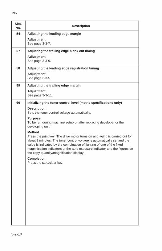
195
Sim.No.
Description
54 Adjusting the leading edge margin
AdjustmentSee page 3-3-7.
57 Adjusting the trailing edge blank cut timing
AdjustmentSee page 3-3-9.
58 Adjusting the leading edge registration timing
AdjustmentSee page 3-3-5.
59 Adjusting the trailing edge margin
AdjustmentSee page 3-3-11.
60 Initializing the toner control level (metric specifications only)
DescriptionSets the toner control voltage automatically.
PurposeTo be run during machine setup or after replacing developer or thedeveloping unit.
MethodPress the print key. The drive motor turns on and aging is carried out forabout 2 minutes. The toner control voltage is automatically set and thevalue is indicated by the combination of lighting of one of the fixedmagnification indicators or the auto exposure indicator and the figures onthe copy quantity/magnification display.
CompletionPress the stop/clear key.
3-2-10

195
Sim.No.
Description
62 Checking/setting the toner control voltage
DescriptionChecks the initial toner control voltage automatically set by simulation 60, orsets the toner control voltage.
PurposeTo be run after replacing the main PCB.
MethodPress the print key. The current setting is indicated by the combination oflighting of one of the fixed magnification indicators or the auto exposureindicator and the figures on the copy quantity/magnification display.
Setting 1. Change the value with the quantity/zoom-up and -down keys.
Setting range: 0.00 to 5.00 V
Reference: 3.00 V
2. Press the print key. The drive motor turns on and the new toner controlvoltage is indicated by the combination of lighting of one of the fixedmagnification indicators or the auto exposure indicator and the figureson the copy quantity/magnification display.
CompletionPress the stop/clear key.
67 Checking ambient temperature and humidity
DescriptionDisplays ambient temperature and humidity.
PurposeTo check if the humidity sensor has a problem.
Method 1. Press the print key.
2. Select the mode to be checked with the exposure adjustment keys.
Mode 1: temperature
Mode 2: relative humidity
Mode 3: absolute humidity
CompletionPress the stop/clear key.
3-2-11

195
Sim.No.
Description
70 Initializing the backup memory
DescriptionInitializes the contents of the backup memory.
PurposeTo be run after replacing the main PCB.
Method 1. Press the print key.
2. Press the exposure mode key. The following data in memory isinitialized.
Sim No.
24
25
2627
28
29
47
54
57
62–1830
00013
00003232
803.50 V2.00 V
01
3.90 V4.05 V4.05 V4.21 V1.05 V
13114012784
Exposure amountManual Exp. 4Manual Exp. 1Manual Exp. +2Lateral magnification (lens travel distance)100% copyEnlargement copyReduction copyLongitudinal magnificationFine adjustment of image focusLens home position for enlargement copyLens home position for reduction copyMirror home position for enlargement copyMirror home position for reduction copyLens home position for 100% copyMirror home position for 100% copyAuto exposurePrescan exposure amountNTC levelNPTC levelEnlargement/reduction-mode exposure amountEnlargement copyReduction copyFixing temperatureStandbyFixing (secondary) stabilizationDuring copyingDuring ejectionFixing drive startLeading edge margin100% copyEnlargement copyReduction copyTrailing edge blank cut timing
Contents Initial data
3-2-12
195-1

195
Sim.No.
Description
70(cont.)
CompletionPress the stop/clear key. After running simulation 70, run the abovesimulations and reenter the settings recorded on the simulation label.
Sim No.
58
596271738589919293969899
1081219195
3.00 V30000Cleared
OnNot installed
20 copiesOn
Metric7 stepsUserNo
Leading edge registration timing100% copyEnlargement copyReduction copyTrailing edge marginToner control voltageMaintenance cycleMaintenance countAuto preheatSetting the presence of the flicker resistorOperation under toner empty conditionAuto startDestinationMemory switch settingMaintenance methodE2000-compliant function
Contents Initial data
3-2-13
195-1

195
Sim.No.
Description
71 Checking/setting the maintenance cycle
DescriptionChecks/sets the maintenance cycle.
PurposeTo be run after replacing the main PCB.
MethodPress the print key. The current setting is shown on the copy quantity/magnification display.
Mode 1: 100,000s and 10,000s digits
Mode 2: 1,000s and 100s digits
Mode 3: 10s and 1s digits
Setting 1. Select the mode to be set with the exposure adjustment keys.
2. Change the setting with the quantity/zoom-up and -down keys.
Setting range: 0 to 999999
Reference: 30000
3. Press the print key. The new setting is stored.
CompletionPress the stop/clear key.
3-2-14

195
Sim.No.
Description
73 Checking/clearing the maintenance count
DescriptionChecks/resets the maintenance count.
PurposeTo be run after replacing the drum and developing units, or before and afterreplacing the main PCB or running simulation 08 (Setting shipping defaults).
MethodPress the print key. The current count is shown on the copy quantity/magnification display.
Mode 1: 100,000s and 10,000s digits
Mode 2: 1,000s and 100s digits
Mode 3: 10s and 1s digits
Setting 1. Select the mode to be set with the exposure adjustment keys.
2. Change the value with the quantity/zoom-up and -down keys.
Setting range: 0 to 999999
Reference: 0
To clear the count, set every digit to 0.
3. Press the print key. The new setting is stored.
CompletionPress the stop/clear key.
3-2-15

195
Sim.No.
Description
85 Selecting between auto preheat on/off
DescriptionTurns the auto preheat function on/off.
PurposeTo be set according to user request.
Setting 1. Change the setting with the quantity/zoom-up and -down keys.
0: Auto preheat function off
1: Auto preheat function on
2. Press the print key. The new setting is stored.
CompletionPress the stop/clear key.
89 Setting the presence of the flicker resistor (240 V/50 Hz specificationsonly)
DescriptionSets the presence of the flicker resistor.
MethodTo be run after the installation of the optional flicker resistor.
Setting 1. Change the setting with the quantity/zoom-up or -down keys.
0: Flicker resistor not installed
1: Flicker resistor installed
Reference: 0
2. Press the print key. The new setting is stored.
CompletionPress the stop/clear key.
3-2-16
195-1

195
Sim.No.
Description
91 Setting operation under the toner empty condition
DescriptionSets the maximum number of copies that can be made under the tonerempty condition.
PurposeTo be set according to user request.
Setting 1. Change the setting with the quantity/zoom-up and -down keys.
Setting range: 0 to 199
Reference: 20
2. Press the print key. The new setting is stored.
CompletionPress the stop/clear key.
3-2-16-1
195-1

195
This page is intentionally left blank.

195
Sim.No.
Description
92 Selecting between auto start on/off
DescriptionTurns the auto start function on/off.
PurposeTo be set according to user request.
Setting 1. Change the setting with the quantity/zoom-up and -down keys.
0: Auto start function off
1: Auto start function on
2. Press the print key. The new setting is stored.
CompletionPress the stop/clear key.
93 Setting the destination
DescriptionSets the destination of the machine.
PurposeTo be run after replacing the main PCB or machine installation.
Setting 1. Change the setting with the quantity/zoom-up and -down keys.
2. Press the print key. The new setting is stored.
CompletionPress the stop/clear key.
Setting
0
1
2
3
4
5
Metric, excluding Spain, Belgium, Peru,
Australia and New Zealand
Inch, excluding the Philippines
Spain
Belgium
Peru, Australia and New Zealand
The Philippines
Contents
3-2-17
195-2

195
Sim.No.
Description
96 Setting the memory switch
DescriptionSets the number of exposure steps for manual mode and the copy limit.
PurposeTo change the number of exposure steps for manual mode or the copy limit.The limit can be set to any number between 1 and 99.
Setting 1. Select the mode with the exposure adjustment keys.
Mode 1: Setting the number of exposure steps for manual mode
Mode 2: Setting the copy limit
2. Change the setting with the quantity/zoom-up and -down keys.
• Mode 1
0: 7 steps
1: 13 steps
Initial value: 0
• Mode 2
Setting range: 1 - 99
Initial value: 99
The setting in mode 2 indicates the limit to the number of copies that can beset on the operation panel. The operation of the quantity/zoom-up key (10sdigit) and quantity/zoom-down key (1s digit) is restricted as in the followingexamples.
• When the setting (the copy limit) is 1
3-2-18
195-2
1s digit
10s digit
1
none (not available)
Copy quantity display

195
Sim.No.
Description
• When the setting (the copy limit) is 5
• When the setting (the copy limit) is 10
• When the setting (the copy limit) is 25
• When the setting (the copy limit) is 50
3-2-18-1
1s digit
10s digit none (not available)
Copy quantity display1 2 3 4 5
1s digit
10s digit
0 is displayed only when the 10s digit is 1.
Copy quantity display1 2 3 4 5 6 7 8 9
none 1
1 can be selected only when the 1s digit is 1.
10s digit
1s digit 0 cannot be selected when there is no tens digit.
When the 10s digit is 2, only numbers between 0 and 5 can be selected.
Copy quantity display1 2 3 4 5 6 7 8 9 0
none 1 2
2 can be selected only when the 1s digit is between 0 and 5.
1s digit
10s digit
0 cannot be selected when there is no tens digit.
Copy quantity display1 2 3 4 5 6 7 8 9 0
none 1 2 3 4 5
5 can be selected only when the 1s digit is 0.
96(cont.)
195-2

195
Sim.No.
Description
• When the setting (the copy limit) is 99
3. Press the print key. The new setting is stored.
CompletionPress the stop/clear key.
3-2-18-2
1s digit
10s digit
0 cannot be selected when there is no tens digit.
Copy quantity display1 2 3 4 5 6 7 8 9 0
none 1 2 3 4 5 6 7 8 9
96(cont.)
195-2

195
Sim.No.
Description
98 Setting the maintenance method (available in Peru, Australia and NewZealand only)
DescriptionSets whether the machine is to be serviced by the user or by servicepersonnel.
PurposeTo be set according to user request.
Setting 1. Change the setting with the quantity/zoom-up and -down keys.
0: User maintenance
1: Service maintenance
2. Press the print key. The new setting is stored.
CompletionPress the stop/clear key.
3-2-18-3
195-2

This page is intentionally left blank.

195
3-3 Assembly and Disassembly3-3-1 Precautions for assembly and disassembly ...................................... 3-3-1
( 1 ) Precautions ............................................................................... 3-3-13-3-2 Paper feed section ............................................................................ 3-3-2
( 1 ) Detaching and refitting paper feed pulleys A and B .................. 3-3-2( 2 ) Replacing the feedshift films ..................................................... 3-3-4( 3 ) Adjustments after installing roller and clutches ......................... 3-3-5
(3-1) Adjusting leading edge registration timing ........................ 3-3-5(3-2) Adjusting the leading edge margin ................................... 3-3-7(3-3) Adjusting the trailing edge blank cut timing ...................... 3-3-9(3-4) Adjusting the trailing edge margin .................................. 3-3-11
3-3-3 Main charging section ..................................................................... 3-3-13( 1 ) Replacing the charger wire ...................................................... 3-3-13
3-3-4 Exposure section ............................................................................. 3-3-16( 1 ) Detaching and refitting the halogen lamp ................................ 3-3-16( 2 ) Detaching and refitting the optical section thermostat ............. 3-3-17( 3 ) Adjusting the positions of the light adjusters ........................... 3-3-18( 4 ) Detaching and refitting the scanner wires ............................... 3-3-19
(4-1) Detaching the scanner wires .......................................... 3-3-19(4-2) Installing the scanner wires ............................................ 3-3-21
( 5 ) Adjusting longitudinal image squareness(inclination of light source 2) .................................................... 3-3-30
( 6 ) Adjusting lateral image squareness(height of light source 2) .......................................................... 3-3-31
( 7 ) Making fine adjustment to image focus .................................... 3-3-32(7-1) Adjusting the mirror home position for
100% copying .................................................................. 3-3-33(7-2) Adjusting the mirror home position for
enlargement mode ........................................................... 3-3-35(7-3) Adjusting the mirror home position for
reduction mode ................................................................ 3-3-36( 8 ) Setting the exposure amount .................................................. 3-3-37( 9 ) Adjusting the auto exposure .................................................... 3-3-41(10) Adjusting exposure amount for enlargement
/reduction mode. ...................................................................... 3-3-42(10-1) Adjusting exposure amount for enlargement mode
(141%) ......................................................................... 3-3-43(10-2) Adjusting exposure amount for reduction mode
(70%) ........................................................................... 3-3-44(11) Adjusting lateral magnification
(correcting the lens travel distance) ........................................ 3-3-45(11-1) Correcting the lens travel distance for
100% copying .............................................................. 3-3-46(11-2) Correcting the lens travel distance for
enlargement copying.................................................... 3-3-47(11-3) Correcting the lens travel distance for
reduction copying ......................................................... 3-3-48(12) Adjusting longitudinal magnification (scanning speed) ............ 3-3-49

195-1
3-3-5 Drum section (metric specification only) ......................................... 3-3-50( 1 ) Detaching and refitting the drum ............................................. 3-3-50( 2 ) Cleaning the drum ................................................................... 3-3-52
3-3-6 Developing section (metric specification only) ................................ 3-3-53( 1 ) Replacing developer ................................................................ 3-3-53( 2 ) Adjusting the formation position of the magnetic
brush (reference) .................................................................. 3-3-54-1( 3 ) Adjusting developing bias voltage (reference) ..................... 3-3-54-2
3-3-7 Transfer section .............................................................................. 3-3-55( 1 ) Replacing the charger wires .................................................... 3-3-55
3-3-8 Cleaning section (metric specification only) .................................... 3-3-59( 1 ) Replacing the cleaning blade .................................................. 3-3-59( 2 ) Detaching and refitting the lower cleaning blade ..................... 3-3-61
3-3-9 Fixing section .................................................................................. 3-3-62( 1 ) Detaching and refitting the fixing heater .................................. 3-3-62( 2 ) Detaching and refitting the fixing unit thermistor ..................... 3-3-65( 3 ) Detaching and refitting fixing thermostats 1 and 2 .................. 3-3-66( 4 ) Detaching and refitting the press roller .................................... 3-3-67( 5 ) Detaching and refitting the heat roller ..................................... 3-3-69( 6 ) Detaching and refitting the heat roller separation claws .......... 3-3-71( 7 ) Detaching and refitting the fixing blade ................................... 3-3-72

195
3-3-1
3-3-1 Precautions for assembly and disassembly
( 1 ) Precautions• Be sure to turn the main switch off and disconnect the power plug before starting
disassembly.• When handling PCBs, do not touch connectors with bare hands or damage the board.• Do not touch any PCB containing IC’s with bare hands or any object prone to static
charge.• Use only the specified parts to replace the fixing unit or optical section thermostats.
Never substitute simple wire or similar for thermostats since the copier may beseriously damaged. When installing a thermostat, ensure the correct clearance, ifspecified, using a thickness gauge.
• Use the following testers when measuring voltages:Hioki 3200Sanwa MD-180CSanwa YX-360TRBeckman TECH300Beckman DM45Beckman 330 (capable of measuring RMS values)Beckman 3030 (capable of measuring RMS values)Beckman DM 850 (capable of measuring RMS values)Fluke 8060A (capable of measuring RMS values)Arlec DMM1050Arlec YF1030C
• Prepare the following as test originals: 1. NTC (new test chart) 2. NPTC (newspaper test chart) 3. Blue graph paper

195
3-3-2
3-3-2 Paper feed section
( 1 ) Detaching and refitting paper feed pulleys A and BClean or replace paper feed pulleys A or B as follows.
Procedure 1. Detach the drawer. 2. Detach the rear cover. 3. Release the lever of the paper feed clutch with a straight screwdriver in the direction
of the arrow.
LeverPaper feed clutch
Figure 3-3-1
4. Turn the paper feed shaft to an angle of 180 degrees where paper feed pulleys Aand B can be seen.
Paper feed pulley B
Paper feed pulley A Paper feed pulley B
Figure 3-3-2
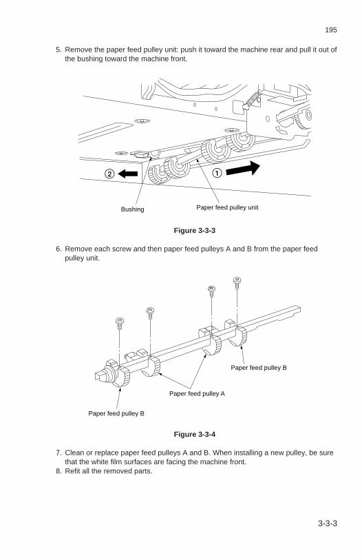
195
3-3-3
5. Remove the paper feed pulley unit: push it toward the machine rear and pull it out ofthe bushing toward the machine front.
12
Bushing Paper feed pulley unit
Figure 3-3-3
6. Remove each screw and then paper feed pulleys A and B from the paper feedpulley unit.
Paper feed pulley B
Paper feed pulley A
Paper feed pulley B
Figure 3-3-4
7. Clean or replace paper feed pulleys A and B. When installing a new pulley, be surethat the white film surfaces are facing the machine front.
8. Refit all the removed parts.

195
3-3-4
( 2 ) Replacing the feedshift filmsReplace the feedshift films as follows.
Procedure 1. Open the front cover and take the toner cartridge out of the copier. 2. Unlock the developing unit release lever and remove the developing unit and drum
unit. 3. Remove the left, right, front left and front right covers. 4. Remove the E-ring holding the release unit shaft and detach the unit in the direction
of the arrow in the figure.
Release unit
E-ring
Figure 3-3-5
5. Replace the feedshift films by aligning their edges with the line a shown in thefigure.
a
Feedshift films
Figure 3-3-6
6. Refit all the removed parts.

195
3-3-5

195
3-3-6
End
Press the stop/clear key.
Setting range: 89 to 249Reference:
108 for 100% copy121 for enlargement copy91 for reduction copy
Change per step: 0.12 mmIncreasing the value makes the timing of the second paper feed earlier, and reducing it makes the timing later.
Exit simulation mode.
AB
Yes
No
Adjust another mode?
Original Copy example 1 Copy example 2
Figure 3-3-7

195
3-3-7
(3-2) Adjusting the leading edge marginAdjust the leading edge margin as follows if it is not within the specified range.
No. 58(page 3-3-5)
No. 54
Important: Before starting this adjustment, ensure the above simulations have beencompleted.
Procedure
Start
Enter simulation mode.
Enter 54 with the numeric keys.
Press the print key.
Select the mode to be adjusted with the copy exposure adjust-ment keys.
Press the zoom input/enter key. Press the print key.
Mode 1: 100% copyMode 2: enlargement (141%) copyMode 3: reduction (70%) copy
*1 Specified setting3 mm for 100% copy4.5 mm for enlargement copy3 mm for reduction copy
Change the setting with the zoom-up/down key.
Place an A4/81/2" × 11" sheet on the contact glass with the original holder open (see Figure 3-3-8).
Press the print key and make a test copy.
The new setting is stored.
AB
No
Yes
Is leading edge margin A within the specified
range*1?
The current setting is displayed.
Test copy mode is set.

195
3-3-8
End
Press the stop/clear key.
Setting range: 25 to 167References:
131 for 100% copy140 for enlargement copy127 for reduction copy
Change per step: 0.12 mmIncreasing the value makes the margin wider, and reducing it makes the margin narrower.
Exit simulation mode.
AB
Yes
No
Adjust another mode?
A4/81/2" × 11" sheet
Contact glass
Figure 3-3-8
A
A: Use a scale to measure accurately.
Figure 3-3-9

195
3-3-9
(3-3) Adjusting the trailing edge blank cut timingAdjust the trailing edge blank cut timing as follows if the trailing edge margin is not 5 ± 3mm (inch specs) or 15 ± 3 mm (metric specs).
No. 58(page 3-3-5)
No. 54(page 3-3-7)
No. 57
Important: Before starting this adjustment, ensure the above simulations have beencompleted.
Procedure
Start
Enter simulation mode.
Enter 57 with the numeric keys.
Press the print key.
Press the zoom input/enter key. Press the print key.
Change the setting with the zoom-up/down key.
*1 Setting range:5 mm ± 3 mm (inch specs)15 mm ± 3 mm (metric specs)
Place the maximum size of sheet on the contact glass with the origi-nal holder open (see Figure 3-3-10).
Press the print key to make a test copy.
The new setting is stored.
A
No
Yes
Is the trailing edge margin within the
setting range?*1
The current setting is displayed.
Test copy mode is set.

195
3-3-10
End
Press the stop/clear key.Setting range: 0 to 84Reference: 84Change per step: 0.12 mmIncreasing the value makes the margin wider, and decreasing it makes the margin narrower.
Exit simulation mode.
A
Contact glass
Copy paper (maximum size)
Figure 3-3-10
A
A: Use a scale to measure accurately
Figure 3-3-11

195
3-3-11
(3-4) Adjusting the trailing edge marginAdjust the trailing edge margin as follows if it is not 0 mm.
No. 58(page 3-3-5)
No. 54(page 3-3-7)
No. 57(page 3-3-9)
No. 59
Important: Before starting this adjustment, ensure the above simulations have beencompleted.
Procedure
Start
Enter simulation mode.
Enter 59 with the numeric keys.
Press the print key.
Press the zoom input/enter key. Press the print key.
Change the setting with the zoom-up/down keys
Place an A4/81/2" × 11" sheet on the contact glass with the original holder open (see Figure 3-3-12).
Press the print key to make a test copy.
The new setting is stored.
A
No
Yes
Is the trailing edge margin A 0 mm?
The current setting is displayed.
Test copy mode is set.

195
3-3-12
End
Press the stop/clear key.Setting range: 10 to 110Reference: 95Change per step: 0.2 mm Increasing the value makes the margin wider, and decreasing it makes the margin narrower.
Exit simulation mode.
A
Contact glass
A4/81/2" × 11" sheet
Figure 3-3-12
A
A: Use a scale to measure accurately.
Figure 3-3-13

195
3-3-13
3-3-3 Main charging section
( 1 ) Replacing the charger wireTake the following procedure when the charger wire is broken or to be replaced.
Precautions• Use the specified tungsten wire for the charger wire.• The part of the wire wrapped around the charger spring must not protrude from the
charger housing.• The cut end of the charger wire must not protrude more than 2 mm from under the
charger wire retainer pin.• Use a clean, undamaged tungsten charger wire.• Keep the charger wire taut by ensuring that the charger spring is under tension.• Clean the main charger shield first with a damp cloth and then with a dry cloth when
replacing the charger wire.Caution: Do not use organic solvents such as alcohol or thinner to clean the main
charger.
Procedure 1. Open the front cover and take the toner cartridge out of the copier. 2. Unlock the developing unit release lever and remove the developing unit and drum
unit. 3. Remove the screw and main charger retainer.
Main charger retainer Screw
Figure 3-3-14

195
3-3-14
4. Remove the main charger. 5. Remove the main charger front and rear lids with a straight screwdriver. 6. Remove the charger wire retainer pin and charger spring, then the charger wire.
Main charger rear lid
Charger spring
Charger wire
Main charger front lid
Charger wire retainer pin
Figure 3-3-15
7. Wind the new tungsten wire at least five turns around one end of the charger spring.• The length of the cut wire must be less than 2 mm.
8. Hook the other end of the charger spring onto the main charger terminal of the maincharger rear housing.
2 mm or less
Main charger terminal
Charger spring Charger wire
Figure 3-3-16

195
3-3-15
9. Run the wire through the notch in the main charger front and rear housing and pull ittight so that the distance from the end of the charger spring to the notch in the maincharger rear housing is between 7 and 9 mm.
7 to 9 mm
Charger spring Notch
Figure 3-3-17
10. Insert the retainer pin into the main charger front housing to fix the charger wire11. Cut off the excess wire under the retainer pin so less than 2 mm protrudes.
2 mm or less
Charger wire Charger wire retainer pin
Figure 3-3-18
12. Refit the front and rear lids to the main charger.• Ensure that the larger lid is refit to the front housing and smaller lid to the rear
housing.13. Refit all the removed parts.

195
3-3-16
3-3-4 Exposure section
( 1 ) Detaching and refitting the halogen lampClean or replace the halogen lamp as follows.
Procedure 1. Remove the rear and right covers, then the contact glass. 2. Move light source unit 1 to the cutout in the copier rear. 3. Press the lamp terminal at the copier rear in the direction of the arrow and remove it
from the halogen lamp. 4. Remove the halogen lamp from the cutout in the copier rear.
• When removing the lamp, touch only the ceramic parts.
Lamp terminal
Halogen lamp
Figure 3-3-19
5. Clean or replace the halogen lamp.• When replacing the halogen lamp, ensure that the projection of the lamp is facing
up so that it does not come in contact with the other parts such as the reflectors. 6. Refit all the removed parts.

195
3-3-17
( 2 ) Detaching and refitting the optical section thermostatCheck or replace the optical section thermostat as follows.Caution: Use the specified thermostat for replacement. Do not substitute a simple wire
or similar; otherwise, the copier will be seriously damaged.
Procedure 1. Remove the right cover, then the contact glass. 2. Remove the fast-on terminals of the optical section thermostat. 3. Check for continuity across the terminals using a tester. 4. If none, remove the two screws and then the optical thermostat, and fit a new
thermostat.
Optical section thermostat
Fast-on terminals
Figure 3-3-20
5. Refit all the removed parts.

195
3-3-18
( 3 ) Adjusting the positions of the light adjustersPerform the following adjustment after refitting or replacing the light adjusters, or if thecopy image is abnormally light or dark on one side.• Before starting this adjustment, be sure that the main and transfer charges, mirrors
and dust filter are not stained with toner.
Procedure
Start
End
Make a test copy at 100% with the maximum size of copy paper.
No
Yes
Is the copy image correct?
Adjust the positions of the light ad-justers.
• If the copy image is not correct on the machine front, adjust the light adjuster on themachine rear.
• If the copy image is not correct on the machine rear, adjust the light adjuster on themachine front.
• Moving an adjuster to the machine right (e) makes the copy image darker, andmoving it to the machine left (a) makes the copy image lighter.
Light adjusters
Figure 3-3-21

195
3-3-19
( 4 ) Detaching and refitting the scanner wiresPerform the following steps when a scanner wire is broken or to be replaced.Important: After replacing a scanner wire, proceed to “( 5 ) Adjusting longitudinal image
squareness” (see page 3-3-30) and “( 7 ) Making fine adjustment to imagefocus” (see page 3-3-32).
(4-1) Detaching the scanner wires
Procedure 1. Remove the rear, right and left covers, then the contact glass. 2. Remove the front left and front right covers, then the operation unit. 3. Remove the screw holding the scanner feed wire and remove the feed wire
connector.
Clamp
Scanner feed wire
Connector
Figure 3-3-22
4. Remove the scanner feed wire from the feed wire guide.
Feed wire guide
Scanner feed wire
Figure 3-3-23

195
3-3-20
5. Remove each two screws and then the wire retainers on the front and rear of lightsource unit 1.
6. Remove light source unit 1 from the copier.
Light source unit 1
Wire retainers
Figure 3-3-24
7. Unhook the springs on the ends of each scanner wire and remove the scannerwires from each pulley.

195
3-3-21
(4-2) Installing the scanner wires
Required installation jig• Scanner wire drum clips (P/N 75700330)
Procedure 1. Take the fixing unit out of the copier (see page 3-3-62). 2. Remove the eight screws and then the upper left reinforcement plate from the
copier.
Upper leftreinforcement plate
Figure 3-3-25

195
3-3-22
3. Remove the two screws and then the scanner motor from the scanner motor mount.
Scanner motor Scanner motor mount
Figure 3-3-26
4. Remove the E-ring, bushing and the four screws, and then detach the scannermotor mount from the copier.
E-ring Bushing Scanner motor mount
Figure 3-3-27

195
3-3-23
5. Remove the screw and then scanner drive gear 64 from the copier.
Scanner drive gear 64
Figure 3-3-28
6. Remove the E-ring and bushing on the copier front, and then detach scanner wiredrum A from the copier.
Bushing
Scanner wire drum A
E-ring
Figure 3-3-29

195
3-3-24
7. Fit a new scanner wire to scanner wire drum A (on the machine front) as follows.Numbers in circles correspond with those in Figure 3-3-30.1 Holding the scanner wire by the ball furthest from an end, with that longer end on
the right side of the machine and the other end on the left, insert the ball into thehole in scanner wire drum A.
2 Run the shorter end of the scanner wire six times around the drum toward themachine outside.
3 Run the longer end of the wire three times around the drum toward the machineinside.
4 Hold the scanner wire in place with the scanner wire drum clip.
1
3
4
2
Scanner wire drum A
Scanner wire drum clip
Machine left
Machine right
Longer end
Shorter end
Machine front Machine rear
3 turns
6 turns
Figure 3-3-30

195
3-3-25
8. Install the new scanner wire to the scanner wire drum A (on the machine rear) asfollows. Numbers in circles correspond with those in Figure 3-3-31.1 Holding the scanner wire with the ball furthest from an end, with that longer end
from the ball on the right side of the machine and the other end on the left, insertthe ball into the hole in scanner wire drum A.
2 Run the shorter end of the scanner wire six times around the drum toward themachine outside.
3 Run the longer end of the wire three times around the drum toward the machineinside.
4 Hold the scanner wire in place with the scanner wire drum clip.
1
3
4
2
Scanner wire drum A
Scanner wire drum clip
Machine left
3 turns
Machine right
Longer end
Shorter end
Machine front Machine rear
6 turns
Figure 3-3-31

195
3-3-26
9. Refit the scanner wire drum A to the copier.10. Refit scanner drive gear 64, the bushing, scanner motor mount and upper left
reinforcement plate.11. Remove the two screws holding the optical fan motor.
Screws
Optical section fan motor
Figure 3-3-32
12. Move light source unit 2 to the copier center and hold it with the two screwsremoved from the optical section fan motor.
Screw Light source unit 2
Screw
Figure 3-3-33

195
3-3-27
13. Route the scanner wire on the machine front around each pulley as follows.Numbers in circles correspond with those in Figure 3-3-34.1 Loop the shorter end of the scanner wire around the inner groove in the pulley
on the left side of the machine from bottom to top.2 Loop the wire around the outer groove in the pulley of light source unit 2 from top
to bottom.3 Loop the wire around the inner groove in the pulley in the center of the machine
from top to bottom.4 Hook the spring on the end of the wire temporarily onto its holder on the right
side of the machine.5 Loop the longer end of the wire around the inner groove in the pulley of the
upper right side of the machine from bottom to top.6 Loop the wire around the inner groove in the pulley of light source unit 2 from top
to bottom and then thread wire c between wires a and b from top to bottom.7 Loop the wire around the inner groove in the pulley of the lower right of the
machine from top to bottom.8 Run the wire twice toward the inside of scanner wire drum B and insert the ball
into the hole in the drum.9 Run the wire another two turns around the drum.0 Unhook the spring from its holder in step 4 and hook the two springs together.
1
2
3
b
ca
6
4
5
7 9
8 0
Inner
Outer Inner
Inner
2 turns
2 turnsInner
Inner
Figure 3-3-34

195
3-3-28
14. Route the scanner wire on the machine rear around each pulley as follows.Numbers in circles correspond with those in Figure 3-3-35.1 Loop the shorter end of the scanner wire around the inner groove in the pulley
on the left side of the machine from bottom to top.2 Loop the wire around the outer groove in the pulley of light source unit 2 from top
to bottom.3 Loop the wire around the inner groove in the pulley in the center of the machine
from top to bottom.4 Hook the spring on the end of the wire temporarily onto its holder on the right
side of the machine.5 Loop the longer end of the wire around the inner groove in the pulley of the
upper right side of the machine from bottom to top.6 Loop the wire around the inner groove in the pulley of light source unit 2 from top
to bottom, and then thread wire c between wires a and b from top to bottom.7 Loop the wire around the inner groove in the pulley of the lower right of the
machine from top to bottom.8 Run the wire twice toward the inside of scanner wire drum B and insert the ball
into the hole in the drum.9 Run the wire another two turns around the drum.0 Unhook the spring from its holder in step 4 and hook the two springs together.
1
2
3
6
4
5
79
80
Inner
OuterInner
Inner
2 turns
2 turns Inner
Inner
b
ca
Figure 3-3-35

195
3-3-29
15. Remove the front and rear scanner wire drum clips from scanner wire drum A.16. Remove the screw holding light source unit 2 and refit the optical section fan motor.17. Turn scanner wire drum A and move light source unit 2 all the way toward the
machine right.18. Turn scanner wire drum B until the screw on the front side of the drum can be seen
through the cutout in the upper right reinforcement plate.
Upper right reinforcement plate
ScrewScanner wire drum B
Figure 3-3-36
19. Mount light source unit 1 onto the front and rear scanner rails.• When mounting, ensure that the scanner wire on the top is above light source unit 1.
20. Run the scanner feed wire along the feed wire guide and refit it to the connector onthe machine rear. Refit the clamp to hold the scanner feed wire.• Be sure that the scanner feed wire is not twisted.
21. Move light source unit 1 all the way toward the machine right and refit the wireretainers.
22. Refit all the removed parts.23. Perform “( 5 ) Adjusting longitudinal image squareness” (see 3-3-30) and “( 7 )
Making fine adjustment to image focus” (see 3-3-32).

195
3-3-30
( 5 ) Adjusting longitudinal image squareness (inclination of light source 2)Make the following adjustment after replacing the scanner wires, or if the copy image islongitudinally skewed (longitudinal squareness is not obtained).
Procedure
Start
End
Make a test copy with an A4/81/2" × 11" sheet.
No
Yes
Is the copy image correct?
Tighten the adjustment screw on the scanner wire drum.
Adjust the inclination by loosening the adjustment screw on scanner wire drum B and then turning the drum.
• To correct an image as in copy example 1, turn scanner wire drum B in the direction ofthe black arrow (a).
• To correct an image as in copy example 2, turn scanner wire drum B in the direction ofthe white arrow (e).
Adjustment screw
Scanner wire drum B
Figure 3-3-38
Original Copy example 2Copy example 1
Figure 3-3-37

195
3-3-31
( 6 ) Adjusting lateral image squareness (height of light source 2)Make the following adjustment if the copy image is laterally skewed (lateral squarenessis not obtained).
ProcedureStart
End
Make a test copy with an A4/81/2" × 11" sheet.
No
Yes
Is the copy image in focus?
Tighten the two screws of the mir-ror frame adjustment plate.
Adjust the height of light source unit 2 by turning its adjustment screw.
Loosen the two screws holding the mirror frame adjustment plate.
• To correct an image as in copy example 1, turn the adjustment screw clockwise.• To correct an image as in copy example 2, turn the adjustment screw counterclockwise.Important: Paint-lock the adjustment screw of light source 1 after adjustment.
Adjustment screw
Light source 2
Screws
Mirror frame adjustment plate
Figure 3-3-40
Original Copy example 1 Copy example 2
Figure 3-3-39

195
3-3-32
( 7 ) Making fine adjustment to image focusPerform the following adjustment after replacing the optical wires, or if the entire copyimage is out of focus.
Mode setting procedure
Start
End
Check that exposure is correctly set in “( 8 ) Setting the exposure amount”.
Run simulation “(7-1) Adjusting the mirror home position for 100% copying”.
Run simulation “(7-3) Adjusting the mirror home position for reduc-tion mode”.
Run simulation “(7-2) Adjusting the mirror home position for en-largement mode”.

195
3-3-33
(7-1) Adjusting the mirror home position for 100% copying
Procedure
Start
Enter simulation mode.
Enter 25 with the numeric keys.
Place the NTC on the contact glass and A4/81/2" × 11" copy pa-per.
Press the print key.
Select the mode to be adjusted and change the setting to 0.
Press the stop/clear key.
Enter 27 with the numeric keys.
Press the print key.
Select the mode to be adjusted and change the setting to 0 for modes 1 to 4 and 32 for modes 5 and 6 with the zoom up/down keys.
Select mode 6 with the copy expo-sure adjustment keys.
· · · · · · · The current setting is displayed.
A

195
3-3-34
Press the zoom input/enter key.
Press the print key.
Change the setting with the zoom up/down keys.
Setting range: 0 to 63Reference: 32
Press the print key to make a test copy.
Press the stop/clear key.
Exit simulation mode.
The new setting is stored.
No
Yes
Is the copy image in focus?
· · · · · · · Test copy mode is set.
A
End

195
3-3-35
(7-2) Adjusting the mirror home position for enlargement mode
Procedure
Start
End
Enter simulation mode.
Enter 27 with the numeric keys.
Press the print key.
Press the stop/clear key.
Exit simulation mode.
Select mode 3 with the copy expo-sure adjustment keys.
Place the NTC on the contact glass and A4/81/2" × 11" copy pa-per.
Press the zoom input/enter key.
Press the print key.
Change the setting with the zoom up/down keys.
Setting range: –8 to 8Reference: 0
Press the print key to make a test copy at 141%.
The new setting is stored.
No
Yes
Is the copy image in focus?
· · · · · · · The current setting is displayed.
· · · · · · · Test copy mode is set.

195
3-3-36
(7-3) Adjusting the mirror home position for reduction mode
Procedure
Start
End
Enter simulation mode.
Enter 27 with the numeric keys.
Press the print key.
Press the stop/clear key.
Exit simulation mode.
Select mode 4 with the copy expo-sure adjustment keys.
Place the NTC on the contact glass and A4/81/2" × 11" copy pa-per.
Press the zoom input/enter key.
Press the print key.
Change the setting with the zoom up/down keys.
Setting range: –8 to 8Reference: 0
Press the print key to make a test copy at 70%.
The new setting is stored.
No
Yes
Is the copy image in focus?
· · · · · · · The current setting is displayed.
· · · · · · · Test copy mode is set.

195
3-3-37
( 8 ) Setting the exposure amountPerform the following adjustment when the drum is replaced.
Precautions• Check that the developer density is correct.• Check that the halogen lamp has not deteriorated.• Clean the optical system.• Never touch controls VR1, VR2 or VR3 on the AVR PCB.
Mode setting procedure
Start
End
Select mode 1 (manual Exp. 4).
Select mode 2 (manual Exp. 1).
Select mode 3 (manual Exp. +2).

195
3-3-38
Procedure
Start
Enter simulation mode.
Enter 24 with the numeric keys.
Press the print key.
Place the NTC on the contact glass and select mode 1 with the copy exposure adjustment keys.
Press the zoom input/enter key.
Press the print key.
Decrease the setting with the zoom-down key.
Increase the setting with the zoom-up key.
Increasing the value makes the image lighter, and decreasing it makes the image darker.
Setting range: 20 to 100Reference: 62
Press the print key to make a test copy at Exp. 4.
The new setting is stored.
A
Yes
No
Yes
No
Is the image abnormally light?
Is the image abnormally dark?
· · · · · · · The current setting is displayed.
· · · · · · · Test copy mode is set.

195
3-3-39
Place the blue graph paper on the contact glass and select mode 2 with the copy exposure adjust-ment keys.
Press the zoom input/enter key.
Press the print key.
Decrease the setting with the zoom-down key.
Increase the setting with the zoom-up key.
Increasing the value makes the image lighter, and decreasing it makes the image darker.
Setting range: –40 to 0Reference: –18
Press the print key to make a test copy at Exp. 1.
The new setting is stored.
B
Yes
No
Yes
No
Is the image abnormally light?
Is the image abnormally dark?
· · · · · · · The difference from the setting in mode 1 (Exp. 4) is displayed.
· · · · · · · Test copy mode is set.
A

195
3-3-40
Place the NPTC on the contact glass and select mode 3 with the copy exposure adjustment keys.
Press the zoom input/enter key.
Press the print key.
Decrease the setting with the zoom-down key.
Increase the setting with the zoom-up key.
Increasing the value makes the image lighter, and decreasing it makes the image darker.
Setting rage: 0 to 50Reference: 30
Press the print key to make a test copy at Exp. +2.
Press the stop/clear key.
Exit simulation mode.
The new setting is stored.
Yes
No
Yes
No
Is the image abnormally light?
Is the image abnormally dark?
· · · · · · · The difference from the setting in mode 1 (Exp. 4) is displayed.
· · · · · · · Test copy mode is set.
B
End

195
3-3-41
( 9 ) Adjusting the auto exposure
Procedure
Start
End
Check that exposure is correctly set in “( 8 ) Setting the exposure amount”.
Enter simulation mode.
Enter 28 with the numeric keys.
Press the print key.
Select mode 1 with the exposure adjustment keys.
Place five sheets of A4/81/2" × 11" plain white paper on the contact glass.
Press the copy size key. Prescan is performed repeatedly until the output level stabilizes at around the reference. Prescan then stops automatically.*1
Select mode 2 with the exposure adjustment keys.
Place the NTC on the contact glass.
Press the copy size key to start prescanning.
Select mode 3 with the exposure adjustment keys.
Place the NPTC on the contact glass.
Press the copy size key to start prescanning.
Press the stop/clear key.
Exit simulation mode.
*1 When the AE sensor or exposure lamp is broken, prescanning is repeated until thestop/clear key is pressed.
195-1

195
3-3-42
(10) Adjusting exposure amount for enlargement/reduction modeMake the following adjustment when replacing the main PCB or drum.
Mode setting procedure
Start
End
Check that exposure is correctly set in “( 8 ) Setting exposure amount”.
Perform “(10-1) Adjusting expo-sure amount for enlargement mode”.
Perform “(10-2) Adjusting expo-sure amount for reduction mode”.

195
3-3-43
(10-1) Adjusting exposure amount for enlargement mode (141%)
Procedure
Start
End
Enter simulation mode.
Enter 29 with the numeric keys.
Press the print key.
Press the stop/clear key.
Exit simulation mode.
Select mode 1 with the exposure adjustment keys.
Place the NTC on the contact glass and A4/81/2" × 11" copy pa-per.
Press the zoom input/enter key.
Press the print key.
Decrease the setting with the zoom-down key.
Increase the setting with the zoom-up key.
Setting range: –20 to 20Reference: 0Increasing the value makes the image lighter, and decreasing it makes the image darker.
Press the print key to make a test copy at 141%.
The new setting is stored.
Yes
No
Yes
No
Is the copy image abnormally light?
Is the copy image abnormally dark?
· · · · · · · The difference from the setting in simulation 24-1 is displayed.
· · · · · · · Test copy mode is set.
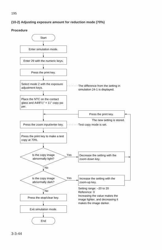
195
3-3-44
(10-2) Adjusting exposure amount for reduction mode (70%)
Procedure
Start
End
Enter simulation mode.
Enter 29 with the numeric keys.
Press the print key.
Press the stop/clear key.
Exit simulation mode.
Select mode 2 with the exposure adjustment keys.
Place the NTC on the contact glass and A4/81/2" × 11" copy pa-per.
Press the zoom input/enter key.
Press the print key.
Decrease the setting with the zoom-down key.
Increase the setting with the zoom-up key.
Setting range: –20 to 20Reference: 0Increasing the value makes the image lighter, and decreasing it makes the image darker.
Press the print key to make a test copy at 70%.
The new setting is stored.
Yes
No
Yes
No
Is the copy image abnormally light?
Is the copy image abnormally dark?
· · · · · · · The difference from the setting in simulation 24-1 is displayed.
· · · · · · · Test copy mode is set.

195
3-3-45
(11) Adjusting lateral magnification (correcting the lens travel distance)Make the following adjustment if the lateral magnification is not correct.
Mode setting procedure
Start
End
Check that exposure is set cor-rectly in “( 8 ) Setting exposure amount”.
Perform “(11-1) Correcting the lens travel distance for 100% copying”.
Perform “(11-2) Correcting the lens travel distance for enlarge-ment copying”.
Perform “(11-3) Correcting the lens travel distance for reduction copying”.

195
3-3-46
(11-1) Correcting the lens travel distance for 100% copying
Procedure
Start
End
Enter simulation mode.
Enter 25 with the numeric keys.
Press the print key.
Press the stop/clear key.
Exit simulation mode.
Select mode 1 with the exposure adjustment keys.
Place the NTC on the contact glass and A4/81/2" × 11" copy pa-per.
Press the zoom input/enter key.
Press the print key.
Decrease the setting with zoom-down key.
Increase the setting with zoom-up key.
Setting range: –20 to 20Reference: 0Change per step: 0.1%Increasing the value makes the wider, and decreasing it makes the image narrower.
Press the print key to make a test copy.
The new setting is stored.
Yes
No
Yes
No
Is the copy image too wide?
Is the copy image too narrow?
· · · · · · · The current setting is displayed.
· · · · · · · Test copy mode is set.

195
3-3-47
(11-2) Correcting the lens travel distance for enlargement copying
Procedure
Start
End
Enter simulation mode.
Enter 25 with the numeric keys.
Press the print key.
Press the stop/clear key.
Exit simulation mode.
Select mode 2 with the exposure adjustment keys.
Place the NTC on the contact glass and A4/81/2" × 11" copy pa-per.
Press the zoom input/enter key.
Press the print key.
Decrease the setting with zoom-down key.
Increase the setting with zoom-up key.
Setting range: –20 to 20Reference: 0Change per step: 0.1%Increasing the value makes the image wider, and decreasing it makes the image narrower.
Press the print key to make a test copy at 141%.
The new setting is stored.
Yes
No
Yes
No
Is the copy image too wide?
Is the copy image too narrow?
· · · · · · · The current setting is displayed.
· · · · · · · Test copy mode is set.

195
3-3-48
(11-3) Correcting the lens travel distance for reduction copying
Procedure
Start
End
Enter simulation mode.
Enter 25 with the numeric keys.
Press the print key.
Press the stop/clear key.
Exit simulation mode.
Select mode 3 with the exposure adjustment keys.
Place the NTC on the contact glass and A4/81/2" × 11" copy pa-per.
Press the zoom input/enter key.
Press the print key.
Decrease the setting with zoom-down key.
Increase the setting with zoom-up key.
Setting range: –20 to 20Reference: 0Change per step: 0.1%Increasing the value makes the image wider, and decreasing it makes the image narrower.
Press the print key to make a test copy at 70%.
The new setting is stored.
Yes
No
Yes
No
Is the copy image too wide?
Is the copy image too narrow?
· · · · · · · The current setting is displayed.
· · · · · · · Test copy mode is set.

195
3-3-49
(12) Adjusting longitudinal magnification (scanning speed)Perform the following adjustment if the longitudinal magnification is not correct.
Procedure
Start
End
Enter simulation mode.
Enter 26 with the numeric keys.
Press the stop/clear key.
Exit simulation mode.
Press the print key.
Place the NTC on the contact glass and A4/81/2" × 11" copy pa-per.
Press the zoom input/enter key.
Press the print key.
Decrease the setting with zoom-down key.
Increase the setting with zoom-up key.
Setting range: 1 to 20Reference: 13Change per step: 0.2%Increasing the value makes the image longer, and decreasing it makes the image shorter.
Press the print key to make a test copy.
The new setting is stored.
Yes
No
Yes
No
Is the copy image too long?
Is the copy image too short?
· · · · · · · The current setting is displayed.
· · · · · · · Test copy mode is set.

195
3-3-50
3-3-5 Drum section (metric specification only)
( 1 ) Detaching and refitting the drumPerform the following steps when cleaning or replacing the drum.
Precautions• Avoid direct sunlight and strong light when detaching and refitting the drum.• Hold the drum at the ends and never touch the drum surface.• After removing the drum, keep it in the drum case or storage bag to protect the
surface from light.
Procedure 1. Open the front cover and take the toner cartridge out of the copier. 2. Unlock the developing unit release lever and detach the developing unit and drum
unit. 3. Remove the screw and then the drum pin from the drum unit. 4. Detach the drum from the drum unit. 5. Remove the bushing from the drum and pull out the drum shaft.
Drum unit
Drum shaft
Drum pin
Drum
Bushing
Figure 3-3-41

195
3-3-51
6. Replace the drum. 7. Refit all the removed parts.
• When refitting the drum pin, ensure that it is inserted correctly into the drum shaftso that the D-cut part of the pin corresponds with that of drum shaft.

195
3-3-52
( 2 ) Cleaning the drumClean the drum as follows when an image problem occurs, or if the drum is dirty.
Precautions• Avoid direct sunlight and strong light when cleaning the drum.• Dust in the air and from the cleaning pad may damage the drum during operation.
Avoid working in dusty place.• Clean the drum entirely even if it is only dirty locally.• Do not clean the drum with alcohol, thinner or other organic solvent.
Required supplies• Polishing cloth: specified synthetic cotton• Toner
Procedure 1. Detach the drum (see page 3-3-50). 2. Apply a polishing cloth to the drum and gently wipe the drum taking care not to
damage the surface. 3. Apply toner to another cloth and wipe the drum surface with it in the same manner. 4. Refit the drum. 5. Refit all the removed parts and let the copier stand for 30 minutes. 6. Make a test copy and check the image.
Drum
Polishing cloth
Figure 3-3-42

195
3-3-53
3-3-6 Developing section (metric specification only)
( 1 ) Replacing developerPerform the following steps when replacing developer.Important: When replacing developer, place the developing unit on a level surface.
Procedure 1. Open the front cover and take the toner cartridge out of the copier. 2. Unlock the developing unit release lever and detach the developing unit. 3. Remove the four screws and then the developing cover from the developing unit by
pulling the cover in the direction of the arrow in the figure.
Developing unit cover
Developing unit
Figure 3-3-43

195
3-3-54
4. Remove the old developer from the developing unit. 5. Shake the new developer bottle well to agitate the developer. 6. Pour the new developer evenly into the developing unit while turning the gear in the
direction of the arrow in the figure.
Developing unit
Gear
Figure 3-3-44
7. Refit all the removed parts. 8. Turn the main switch on while pressing the print key and stop/clear key. 9. 2 s or less after “ ” is shown on the copy quantity/magnification display, press the
stop/clear key to enter simulation mode.10. Enter 60 with the copy quantity/zoom-up or -down keys and press the print key.11. Press the print key. The toner control voltage is set automatically.12. Press the stop/clear key.13. Enter 01 with the copy quantity/zoom-up or -down keys and press the print key to
exit the simulation mode.

195
3-3-553-3-54-1
( 2 ) Adjusting the formation position of the magnetic brush (reference)Check or adjust when the image density is too light or a background is visible.Note: Check if the amount of the developer is correct before the adjustment.
Procedure 1. Open the front cover and remove the toner cartridge. 2. Unlock the developing unit release lever and remove the developing unit. 3. Remove the developing unit terminal cover from the developing unit (two screws).
Developing unit
Developing unit terminal cover
Figure 3-3-44-1
4. Loosen the screw holding the developing roller retainer. Adjust the developingroller shaft using a scale so that the distance between the top of the magneticbrush and the bottom of the developing unit housing is 12.5 mm (referencevalue).
A
A:12.5 mm
Developing roller retainerScrew
Developing roller shaft
Figure 3-3-44-2
5. Refit the removed parts. 6. Make a test copy and check the copy image.
195-1

195
3-3-563-3-54-2
( 3 ) Adjusting developing bias voltage (reference)Make the following adjustment if VR DB on the high voltage PCB has been accidentallyturned. Be sure to turn VR DB only when absolutely necessary.
Adjustment tools• Tester
Procedure
No
Yes
Start
End
Run simulation 33.
Enter the simulation mode.
If the developing bias is set above the reference level, the copy image is too light; if it is below the reference level, a dark background shows.
*
Is the developingbias correct (reference
value: 270 V)?
Press stop/clear.
With the developing unit removed from the machine, connect the tester positive terminal to the purple DB terminal of the high voltage PCB and the negative one to ground (an uncoated area on the frame).
Turn VR DB on the high voltage PCB clockwise ( ) to increase the voltage; turn it counterclock-wise ( ) to decrease it*.
Exit the simulation mode.
Turn the main switch off and disconnect the tester terminals.
e
a
Figure 3-3-44-3 Adjusting developing bias
Tester
Ground
VR DB
DB terminal
195-1

195
3-3-57
3-3-7 Transfer section
( 1 ) Replacing the charger wiresPerform the following steps when the transfer charger wire is broken or is to bereplaced.
Precautions• Use the specified tungsten wire for the charger wire.• The part of the wire wrapped around the charger spring must not protrude from the
charger housing.• The cut end of the charger wire must not protrude more than 2 mm from under the
charger wire retainer pin.• Use a clean, undamaged tungsten charger wire.• Keep the charger wire taut by ensuring the charger spring is under tension.• Clean the transfer charger shield first with a damp cloth and then with a dry cloth when
replacing the charger wire.Caution: Do not clean the transfer charger shield with alcohol, thinner or other organic
solvent.
Procedure 1. Open the release unit. 2. Loosen the pins on the front and rear of the release unit.
Pin
Release unit
Pin
Figure 3-3-45
3-3-55

195
3-3-58
3. Remove the connector of the transfer unit and detach the unit.
Connector
Transfer unit
Figure 3-3-46
4. Remove the three screws and then the pre-transfer guide from the transfer unit. 5. Remove the screw holding each of the front and rear transfer stoppers and then
detach the stoppers from the transfer unit. 6. Remove the transfer charger front and rear transfer lids with a straight screwdriver. 7. Remove the charger wire retainer pin and charger spring, then the charger wire.
Transfer charger rear lid
Charger spring
Transfer charger rear stopper
Transfer unit
Pre-transfer guide
Charger wire
Transfer charger front lid
Charger wire retainer pin
Transfer charger front stopper
Figure 3-3-47
3-3-56
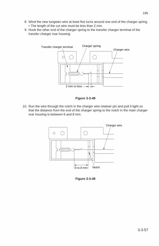
195
3-3-59
8. Wind the new tungsten wire at least five turns around one end of the charger spring.• The length of the cut wire must be less than 2 mm.
9. Hook the other end of the charger spring to the transfer charger terminal of thetransfer charger rear housing.
2 mm or less
Transfer charger terminal Charger springCharger wire
Figure 3-3-48
10. Run the wire through the notch in the charger wire retainer pin and pull it tight sothat the distance from the end of the charger spring to the notch in the main chargerrear housing is between 6 and 8 mm.
6 to 8 mm
Charger wire
Notch
Figure 3-3-49
3-3-57

195
3-3-60
11. Press the retainer pin into the projection of the main charger front housing, soholding the charger wire with it.
12. Cut off the excess wire under the retainer pin so less than 2 mm protrudes.
2 mm or less
Charger wire Charger wire retainer pin
Figure 3-3-50
13. Refit the front and rear lids to the transfer charger.• Ensure that the larger lid is refitted to the front housing and smaller lid to the rear
housing.14. Refit all the removed parts.
3-3-58

195
3-3-61
3-3-8 Cleaning section (metric specification only)
( 1 ) Replacing the cleaning bladeReplace the cleaning blade as follows.
Procedure 1. Open the front cover and take the toner cartridge out of the copier. 2. Unlock the developing unit release lever and detach the developing unit and drum
unit. 3. Detach the drum from the drum unit (see page 3-3-50). 4. Remove the two screws and then the upper cleaning cover from the drum unit.
Upper cleaning cover
Drum unit
Figure 3-3-51
3-3-59

195
3-3-62
5. Remove the two screws and then the cleaning upper cover from the drum unit.
Cleaning blade
Drum unit
Figure 3-3-52
6. Replace the cleaning blade.• When fitting the cleaning blade, ensure that the projections of the drum unit are
seated in the positioning holes in the cleaning blade. 7. Refit all the removed parts.
3-3-60

195
3-3-63
( 2 ) Detaching and refitting the lower cleaning bladeReplace the lower cleaning blade as follows.
Procedure 1. Open the front cover and take the toner cartridge out of the copier. 2. Unlock the developing unit release lever and detach the developing unit and drum
unit. 3. Detach the drum from the drum unit (see page 3-3-50). 4. Remove the two screws and then the lower cleaning blade from the drum unit.
Drum unit
Lower cleaning blade
Figure 3-3-53
5. Replace the cleaning blade.• When fitting the lower cleaning blade, ensure that the projections of the drum unit
are seated in the positioning holes in the cleaning blade. 6. Refit all the removed parts.
3-3-61

195
3-3-64
3-3-9 Fixing section
( 1 ) Detaching and refitting the fixing heaterCheck or replace the fixing heater as follows.
Procedure 1. Detach the left cover. 2. Remove the four connectors of the fixing unit from the copier. 3. Remove the four screws and then the fixing unit from the copier.
Connectors
Fixing unit
Figure 3-3-54
3-3-62

195
3-3-65
4. Remove the four screws and then the copy tray attachment from the fixing unit.
Fixing unit
Figure 3-3-55
5. Remove the two screws and then the fixing unit cover from the fixing unit.
Fixing unit cover
Fixing unit
Figure 3-3-56
3-3-63
195-1

195
3-3-66
6. Remove the fixing unit connector from fixing thermostat 1 (on the copier front). 7. Remove the screw holding each of the front and rear heater mounts, and then
detach them from the fixing unit.
Rear heater mount
Fixing unit
Fixing thermostat 1
Connector
Front heater mount
Figure 3-3-57
8. Pull the fixing heater out via the front of the fixing unit. 9. Check or replace the fixing heater.10. Refit all the removed parts.
3-3-64
195-1

195
3-3-67
( 2 ) Detaching and refitting the fixing unit thermistorCheck, clean or replace the fixing unit thermistor as follows.
Procedure 1. Take the fixing unit out of the copier (see page 3-3-62). 2. Remove the copy tray attachment and fixing unit cover from the fixing unit (see
page 3-3-63). 3. Remove the screw and then the fixing unit thermistor from the fixing unit.
Fixing unit thermistor
Fixing unit
Figure 3-3-58
4. Check, clean or replace the fixing unit thermistor. 5. Refit all the removed parts.
3-3-65
195-1

195
3-3-68
( 3 ) Detaching and refitting fixing thermostats 1 and 2Check or replace thermostats 1 and 2 as follows.Caution: Use the specified thermostat for replacement. Do not substitute a simple wire
or similar; otherwise, the copier will be seriously damaged.
Procedure 1. Take the fixing unit out of the copier (see page 3-3-62). 2. Remove the copy tray attachment and fixing unit cover from the fixing unit (see
page 3-3-63). 3. Remove the connectors of the fixing heater, fixing heater wire and thermostat relay
wire from fixing thermostats 1 and 2. 4. Remove the two screws holding each of the fixing thermostats and then remove the
thermostats from the fixing unit.
Thermostat relay wire
Fixing thermostat 2
Fixing heater wire
Fixing thermostat 1
Fixing heater
Fixing unit
Figure 3-3-59
5. Check or replace fixing thermostat 1 and 2.• When fitting, check the temperature indications on the thermostats and fixing stay,
and install the thermostats in the correct positions. 6. Refit all the removed parts.
3-3-66
195-1

195
3-3-69
( 4 ) Detaching and refitting the press rollerClean or replace the press roller as follows.
Procedure 1. Take the fixing unit out of the copier (see page 3-3-62). 2. Remove the copy tray attachment from the fixing unit (see page 3-3-63). 3. Remove the fixing unit lower housing and heat roller grounding plate from the fixing
unit (two screws).
Fixing unit lower housing
Heat roller grounding plate
Fixing unit
Figure 3-3-60
3-3-67
195-1

195
3-3-70
4. Remove the screw and then the fixing entrance guide from the fixing unit lowerhousing.
5. Remove the press roller from the fixing unit lower housing.
Press roller
Fixing entrance guide Fixing unit lower housing
Figure 3-3-61
6. Clean or replace the press roller. 7. Refit all the removed parts.
• Press the fixing entrance guide all the way down while refitting it.
3-3-68

195
3-3-71
( 5 ) Detaching and refitting the heat rollerClean or replace the heat roller as follows.
Procedure 1. Take the fixing unit out of the copier (see page 3-3-62). 2. Remove the copy tray attachment, fixing unit cover and fixing unit lower housing
from the fixing unit (see page 3-3-63, 67). 3. Remove the three heat roller separation claws from the fixing unit (see page 3-3-
71). 4. Remove the E-ring and then idle gear 20 from the fixing unit.
Fixing unit
E-ring
Idle gear 20
Figure 3-3-62
3-3-69

195
3-3-72
5. Remove the heat roller stopper on the rear of the fixing unit rear, then fixing gear 32and the heat roller bushing.
6. Remove the heat roller stopper on the front of the fixing unit front and then detachthe heat roller bushings.
7. Remove the heat roller from the fixing unit.
Heat roller stopper
Heat roller bushing
Heat roller
Fixing gear 32
Heat roller bushing
Heat roller stopper
Figure 3-3-63
8. Clean or replace the heat roller. 9. Refit all the removed parts.
3-3-70

195
3-3-73
( 6 ) Detaching and refitting the heat roller separation clawsCheck, clean or replace the heat roller separation claws as follows.
Procedure 1. Take the fixing unit out of the copier (see page 3-3-62). 2 Remove the copy tray attachment and fixing unit cover from the fixing unit (see
page 3-3-63). 3. Orient the heat roller separation claws in the direction of the arrows in the figure,
and then detach them.
Fixing unit
Heat roller separation claws
Figure 3-3-64
4. Check, clean and replace the heat roller separation claws. 5. Refit all the removed parts.
3-3-71

195
3-3-743-3-72
( 7 ) Detaching and refitting the fixing bladePerform the following procedure when checking, cleaning or replacing the fixing blade.
Procedure 1. Take the fixing unit out of the copier (see page 3-3-62). 2. Remove the copy tray attachment and fixing unit cover from the fixing unit (see
page 3-3-63). 3. Remove the screw and then the fixing unit thermistor from the fixing unit. 4. Remove the fixing unit thermistor and fixing blade from the fixing unit (one screw).
Fixing thermistor
Fixing unit
Fixing blade
Figure 3-3-65
4. Check, clean or replace the fixing blade.When refitting the fixing blade, make sure that the blade is in contact with the heatroller.
5. Refit all the removed parts.
195-1

195
3-4 PCB Initial Setting3-4-1 Replacing the main PCB ................................................................... 3-4-13-4-2 Adjustment-free variable resistors (VR) ............................................ 3-4-3

195
3-4-1
3-4-1 Replacing the main PCBAfter replacing the main PCB, remove the EEPROM from the old main PCB and fit it tothe new main PCB. If the new EEPROM is used, perform the following steps.
Procedure• Before removing the old EEPROM:
1. Record the user settings of the following items which must be reentered afterreplacement.• Exposure mode• Manual exposure adjustment• Auto exposure adjustment• Auto shutoff on/off• Auto shutoff time• Auto preheat time• Preheat recovery time• Auto clear on/off• Auto clear time
2. Enter simulation mode. 3. Run simulation 73 and record the maintenance count. 4. Exit simulation mode. 5. Turn the main switch off and unplug the power cord. 6. Replace the EEPROM with the new one.

195
3-4-2
• After installing the new EEPROM: 7. Insert the power plug and turn the main switch on. 8. Enter simulation mode. 9. Run simulation 70.10. Run simulation 93 to select the destination.11. Run the following simulations to check or reenter the data recorded on the
simulation label.
12. Exit simulation mode.13. Reenter the contents of the user settings recorded in step 1.
Sim. No. Contents
24 Setting the exposure amount25 Adjusting lateral magnification26 Adjusting longitudinal magnification27 Making fine adjustment to image focus28 Adjusting the auto exposure29 Adjusting exposure amount for enlargement/reduction mode47 Setting the fixing temperature54 Adjusting the leading edge margin57 Adjusting the trailing edge blank cut timing58 Adjusting the leading edge registration timing59 Adjusting the trailing edge margin62 Checking/setting the toner control voltage71 Checking/setting the maintenance cycle73 Checking/clearing the maintenance count85 Selecting between auto preheat on/off89 Setting the presence of the flicker resistor91 Setting operation under the toner empty condition92 Selecting between auto start on/off96 Setting the memory switch98 Setting the maintenance method (available in Peru only)99 Selecting between E2000-compliant function on/off
195-1

195
3-4-3
3-4-2 Adjustment-free variable resistors (VR)The variable resistors listed below are set at the factory prior to shipping and cannot beadjusted in the field.• AVR PCB: VR1, VR2, VR3• High-voltage transformer PCB: VRDB, VRDC

195
3-5 Self-diagnostics3-5-1 Self diagnostic function ..................................................................... 3-5-1
( 1 ) Self diagnostic display ............................................................... 3-5-1

195
3-5-1
3-5-1 Self-diagnostic function
(1) Self-diagnostic displayThis unit is equipped with a self-diagnostic function. When it detects a problem with it-self, it disables copying and displays “C” and a two digit number between 01 and 76 al-ternately on the copy quantity/magnification display in the operation unit, indicating thenature of the problem.After removing the problem, the self-diagnostic function can be reset by opening andclosing the front cover or release unit to turn the safety switch off and back on.
0% Display alternates
21%
Figure3-5-1 Service call code display

195
3-5-2
Turn the main switch off and on, thenrun simulation 70 and re-enter thebackup memory contents.
If C01 persists after re-entering thebackup memory contents, replace themain PCB or EEPROM (IC8).
Replace the main PCB and check forcorrect operation.
Replace the EEPROM (IC8) andcheck for correct operation.
Replace the drive motor.
Check for continuity across the con-nector terminals. If none, replacethem.
Check if rollers and gears rotatesmoothly. If not, grease the bushingsand gears. Check for broken gearsand replace if any.
Replace the main PCB and check forcorrect operation.
Check for the continuity across thescanner motor coil. If none, replacethe scanner motor.
Check if CN10-2 on the main PCBgoes high when the home positionswitch is on and goes low when theswitch is off. If not, replace the homeposition switch.
Check for continuity across the homeposition switch connector terminals. Ifnone, replace them.
C01
C02
C21
C30
Code ContentsRemarks
Causes Check procedures/corrective measures
Self diagnostic codes
Backup memorydata problem.
Defective mainPCB orEEPROM (IC8).
Defective MainPCB.
DefectiveEEPROM (IC8).
Defective rotationcontrol circuit inthe drive motor.
Poor contact inthe connectorterminals.
Defective drivetransmission sys-tem.
Defective mainPCB.
Broken scannermotor coil.
Defective homeposition switch.
Poor contact inthe home posi-tion switch con-nector terminals.
Backup memorydata problem• Abnormal datais written on theEEPROM (IC8).
EEPROM writeproblem• The copier doesnot enter RDYstate more than1 s after startingto write data toEEPROM (IC8).
Drive motorproblem• The drive motoralarm signal(DM ALM) isdetected morethan 2 s afterthe drive motorhas been turnedon.
Scanner motorproblem• The home posi-tion switch doesnot turn offwithin 5 s afterthe scanner mo-tor has startedforward rotation.
• The home posi-tion switch doesnot turn onwithin 7 s afterthe scanner mo-tor has startedreverse rotation.

195
3-5-3
Reinstall the scanner drive belt andadjust the tension.
Reinstall the wire.
Retighten the screws and adjust theimage focus.
Replace the main PCB and check forcorrect operation.
Check for continuity across the coil. Ifnone, replace the lens motor.
Check if CN12-9 on the main PCBgoes high when the lens home posi-tion switch is on and goes low whenthe switch is off. If not, replace thelens home position switch.
Check for continuity across the con-nector terminals. If none, replacethem.
Replace the main PCB and check forcorrect operation.
Check for continuity across the coil. Ifnone, replace the mirror motor.
Check if CN12-3 on the main PCBgoes high when the mirror home posi-tion switch is on and goes low whenthe switch is off. If not, replace themirror home position switch.
Check for continuity across the con-nector terminals. If none, replacethem.
Replace the main PCB and check forcorrect operation.
Code ContentsRemarks
Causes Check procedures/corrective measures
Loose scannerdrive belt.
Loose scannerwire.
Loose screwsholding the scan-ner wire retain-ers.
Defective mainPCB.
Defective lensmotor.
Defective lenshome positionswitch.
Poor contact inthe lens homeposition switchconnector termi-nals.
Defective mainPCB.
Defective mirrormotor.
Defective mirrorhome positionswitch.
Poor contact inthe mirror homeposition switchconnector termi-nals.
Defective mainPCB.
Scanner motorproblem• The home posi-
tion switch doesnot turn offwithin 5 s afterthe scanner mo-tor has startedforward rotation.
• The home posi-tion switch doesnot turn onwithin 7 s afterthe scanner mo-tor has startedreverse rotation.
Lens motorproblem• The lens home
position switchdoes not turn onor off within 5 safter initial op-eration hasstarted.
Mirror motorproblem• The mirror
home positionswitch does notturn on or offwithin 4 s afterinitial operationhas started.
C30
C41
C42

195
3-5-4
Check the charger wire visually. If it isbroken, replace it.
Check the main charger housing. If itis dirty, clean it.
Check the transfer charger wire visu-ally. If it is broken, replace it.
Check the transfer charger housing. Ifit is dirty, clean it.
Detach the main or transfer chargerassembly; if C50 persists, replace thehigh-voltage transformer PCB.
Replace the main PCB and check forcorrect operation.
Check for continuity. If none, replacethe fixing heater.
Check the fixing heater and reinstall ifnecessary.
Check for continuity. If none, replacefixing unit thermostats 1 and 2.
Check the fixing unit thermistor andreinstall if necessary.
Replace the main PCB and check forcorrect operation.
Code ContentsRemarks
Causes Check procedures/corrective measures
C50
C61
Main/transferhigh-voltageproblem• The high-volt-age alarm sig-nal (HV ALM) isdetected morethan 2 s afterthe main high-voltage outputhas been turnedon.
Broken fixingheater filament• The fixing stabi-lization tem-perature is notreached within60 s after fixingcontrol hasstarted.
• The fixing tem-perature dropsbelow 80°C/176°F (fixingunit thermistoroutput voltage:1.06 V DC) afterhaving reachedthe stabilizationlevel.
Broken maincharger wire.
The maincharger leaks.
Broken transfercharger wire.
The transfercharger leaks.
Defective high-voltage trans-former PCB.
Defective mainPCB.
Broken fixingheater filament.
Fixing heaterinstalled incor-rectly.
Fixing unit ther-mostats 1 and 2triggered.
Fixing unit ther-mistor installedincorrectly.
Defective mainPCB.

195
3-5-5
Measure the resistance. If it is ∞ Ω,replace the fixing unit thermistor.
Check for continuity across the con-nector terminals. If none, replacethem.
Replace the main PCB and check forcorrect operation.
Measure the resistance. If it is 0 Ω, re-place the fixing unit thermistor.
Replace the main PCB and check forcorrect operation.
Check that the connectors are in-serted properly.
Measure the resistance across the ex-ternal temperature thermistor. If it is∞ Ω, replace the humidity sensorPCB.
Replace the main PCB and check forcorrect operation.
Code ContentsRemarks
Causes Check procedures/corrective measures
C63
C64
C74
Broken fixingunit thermistorwire• The fixing unit
thermistor out-put voltagedoes not ex-ceed 0.039 VDC within 7 safter fixing con-trol has startedwith the fixingtemperature re-maining below100°C/212°F(fixing unit ther-mistor outputvoltage: 1.71 VDC).
Shorted fixingunit thermistor/abnormally hightemperature• The fixing tem-
perature ex-ceeds 250°C/482°F (fixingunit thermistoroutput voltage:4.73 V DC).
Broken externaltemperaturethermistor wire• The external
temperaturethermistor out-put is below 0.3V DC.
Broken fixing unitthermistor.
Poor contact inthe fixing unitthermistor con-nector terminals.
Defective mainPCB.
Shorted fixingunit thermistor.
Defective mainPCB.
Poor contact inthe humidity sen-sor PCB connec-tors.
Broken externaltemperature ther-mistor wire.
Defective mainPCB.

195
3-5-6
Measure the resistance across the ex-ternal temperature thermistor. If it is0 Ω, replace the humidity sensor PCB.
Replace the main PCB and check forcorrect operation.
Check the contacts.
Replace the developing unit fuse andcheck for correct operation.
Code ContentsRemarks
Causes Check procedures/corrective measures
C75
C76*
Shorted exter-nal temperaturethermistor• The externaltemperaturethermistor out-put is above 4.3V DC.
Developing unitfuse problem• The developingunit fuse doesnot blow within2 s of power be-ing applied to it,just before thedeveloping unitinitializationends.
Shorted externaltemperature ther-mistor.
Defective mainPCB.
Poor contact inthe connector.
Defective devel-oping unit fuse.
* Only for 120 V, 220 V and 240 V specifications.

195
3-6 Troubleshooting3-6-1 Image formation problems ................................................................ 3-6-1
( 1 ) No image (entirely white). .......................................................... 3-6-3( 2 ) No image (entirely black). .......................................................... 3-6-4( 3 ) Image is too light. ...................................................................... 3-6-5( 4 ) Background is visible. ................................................................ 3-6-5( 5 ) A white line appears longitudinally. ........................................... 3-6-6( 6 ) A black line appears longitudinally. ........................................... 3-6-6( 7 ) A black line appears laterally. .................................................... 3-6-7( 8 ) One side of the copy image is darker than the other. ................ 3-6-8( 9 ) Black dots appear on the image. ............................................... 3-6-8(10) Image is blurred. ........................................................................ 3-6-9(11) The leading edge of the image is consistently misaligned
with the original. ........................................................................ 3-6-9(12) The leading edge of the image is sporadically misaligned
with the original. ...................................................................... 3-6-10(13) Paper creases. ........................................................................ 3-6-10(14) Offset occurs. .......................................................................... 3-6-11(15) Black lines appear on both sides of the image
in reducation copies. ............................................................... 3-6-12(16) Image is partly missing. ........................................................... 3-6-12(17) Fixing is poor. .......................................................................... 3-6-13(18) Image is out of focus. .............................................................. 3-6-13(19) Image is not square longitudinally. .......................................... 3-6-13(20) Image is not square laterally. .................................................. 3-6-14(21) Image is partially missing laterally. .......................................... 3-6-14
3-6-2 Paper misfeeds ............................................................................... 3-6-15( 1 ) A paper jam in the registration section is detected
as soon as the main switch is turned on (J03 appears). ......... 3-6-15( 2 ) A paper jam in the eject section is detected as soon as
the main switch is turned on (J02 appears). ............................ 3-6-15( 3 ) A paper jam in the paper drawer is detected during
copying (PF appears). ............................................................. 3-6-15( 4 ) A paper jam in the registration section is detected during
copying (J03 appears). ............................................................ 3-6-16( 5 ) A paper jam in the fixing section is detected during
copying (J01 appears). ............................................................ 3-6-16( 6 ) A paper jam in the eject section is detected during
copying (J02 appears). ............................................................ 3-6-163-6-3 PCB terminal voltages ..................................................................... 3-6-17
( 1 ) Power source PCB .................................................................. 3-6-17( 2 ) Main PCB ................................................................................ 3-6-19( 3 ) AVR PCB................................................................................. 3-6-22( 4 ) Operation unit PCB ................................................................. 3-6-24

195
3-6-4 Electrical problems .......................................................................... 3-6-25( 1 ) The machine does not operate when the main switch
is turned on. ............................................................................. 3-6-25( 2 ) The drive motor does not operate (C21). ................................ 3-6-25( 3 ) The scanner motor does not operate (C30). ........................... 3-6-25( 4 ) The lens motor does not operate (C41). ................................. 3-6-26( 5 ) The mirror motor does not operate (C42). ............................... 3-6-26( 6 ) The toner feed motor does not operate. .................................. 3-6-26( 7 ) The optical section fan motor does not operate. ..................... 3-6-26( 8 ) The fixing unit fan motor does not operate. ............................. 3-6-27( 9 ) The internal cooling fan motor does not operate. .................... 3-6-27(10) The paper feed clutch does not operate. ................................. 3-6-27(11) The registration clutch does not operate. ................................ 3-6-27(12) The halogen lamp does not light. ............................................ 3-6-28(13) The halogen lamp does not turn off. ........................................ 3-6-28(14) The cleaning lamp does not light. ............................................ 3-6-28(15) The fixing heater does not turn on (C61, C63). ....................... 3-6-28(16) The fixing heater does not turn off
(fixing unit thermostat triggered, C64). .................................... 3-6-28(17) Main charging does not take place (C50). ............................... 3-6-29(18) Transfer charging does not take place (C50). ......................... 3-6-29(19) No developing bias is output. .................................................. 3-6-29(20) A paper jam is indicated as soon as the main switch
is turned on. ............................................................................. 3-6-30(21) Others. ..................................................................................... 3-6-30
3-6-5 Mechanical problems ...................................................................... 3-6-31( 1 ) No primary paper feed. ............................................................ 3-6-31( 2 ) No secondary paper feed. ....................................................... 3-6-31( 3 ) Skewed paper feed. ................................................................ 3-6-31( 4 ) The scanner does not travel. ................................................... 3-6-31( 5 ) Multiple sheets of paper are fed at one time. .......................... 3-6-31( 6 ) Paper jams. ............................................................................. 3-6-31( 7 ) Toner drops on the paper conveying path. .............................. 3-6-31( 8 ) Abnormal noise is heard. ......................................................... 3-6-32

195
3-6-1
3-6-1 Image formation problems
Contents
See page 3-6-3. See page 3-6-4. See page 3-6-5. See page 3-6-5.
(1) No image (en-tirely white).
(2) No image (en-tirely black).
(3) Image is too light.
(4) Background is visible.
See page 3-6-6. See page 3-6-6. See page 3-6-7. See page 3-6-8.
(5) A white line ap-pears longitudi-nally.
(6) A black line ap-pears longitudi-nally.
(7) A black line ap-pears laterally.
(8) One side of the copy image is darker than the other.
See page 3-6-8. See page 3-6-9. See page 3-6-9. See page 3-6-10.
(9) Black dots ap-pear on the im-age.
(10) Image is blurred.
(11) The leading edge of the im-age is consist-ently mis-aligned with the original.
(12) The leading edge of the im-age is sporadi-cally mis-aligned with the original.

195
3-6-2
See page 3-6-10. See page 3-6-11. See page 3-6-12. See page 3-6-12.
(13) Paper creases. (14) Offset occurs. (15) Black lines ap-pear on both sides of the image in re-duction copies.
(16) Image is partly missing.
See page 3-6-14.
(21) Image is par-tially missing laterally.
See page 3-6-13. See page 3-6-13. See page 3-6-13. See page 3-6-14.
(17) Fixing is poor. (18) Image is out of focus.
(19) Image is not square long-itudinally.
(20) Image is not square lateral-ly.

195
3-6-3
(1) No image (en-tirely white).
Causes1. No original present.2. No main charging.3. No transfer charging.4. All blank lamps on.5. Developing section not driven.
No original present.
No main charging.
Broken main charger wire.
Leaking main charger housing.
The connector terminals of the high-voltage transformer PCB make poor contact.
Defective main PCB.
Defective high-voltage trans-former PCB.
No transfer charging.
Broken transfer charger wire.
Leaking transfer charger hous-ing.
The connector terminals of the high-voltage transformer PCB make poor contact.
Defective main PCB.
Defective high-voltage trans-former PCB.
All blank lamps on.
Developing section not driven.
Place an original in the correct position.
Replace the wire.
Clean the main charger housing.
Check for continuity across the terminals. If none, replace them.
Run simulation 33 and check if CN8-4 on the main PCB goes low. If not, replace the main PCB.
If main charging does not take place during simu-lation 33 after the main PCB has been found to be normal, replace the high-voltage transformer PCB.
Replace the wire.
Clean the transfer charger housing.
Check for continuity across the terminals. If none, replace them.
Run simulation 33 and check if CN8-4 on the main PCB goes low. If not, replace the main PCB.
If transfer charging does not take place during simulation 33 after the main PCB has been found to be normal, replace the high-voltage transformer PCB.
Run simulation 42 and if the check pattern copy is not obtained, replace the main PCB.
Check the gears driving the developing section and replace any broken gears.
1.
2.
A.
B.
C.
D.
E.
3.
A.
B.
C.
D.
E.
4.
5.
Causes Check procedures/corrective measures

195
3-6-4
(2) No image (en-tirely black).
Causes1. Broken halogen lamp filament.2. Halogen lamp fails to light.
Take the halogen lamp out of the unit and check for continuity across the terminals. If none, re-place it (see page 3-3-16).
Check for continuity. If none, replace the thermo-stat after determining the cause (see page 3-3-17).
Check for continuity across the terminals. If none, replace them.
Run simulation 20 and check if CN7-10 on the main PCB remains low. If it does, replace the main PCB.
If the halogen lamp does not light during simula-tion 20 after the main PCB has been found to be normal, replace the AVR PCB.
1.
2.
A.
B.
C.
D.
Broken halogen lamp filament.
Halogen lamp fails to light.
The optical section thermostat is triggered.
The connector terminals of the AVR PCB make poor contact.
Defective main PCB.
Defective AVR PCB.
Causes Check procedures/corrective measures

195
3-6-5
(3) Image is too light.
Causes1. Insufficient toner.2. Deteriorated developer.3. Misadjusted developing section.4. Dirty or deteriorated drum.
Insufficient toner.
Deteriorated developer.
Misadjusted developing sec-tion.
Dirty or deteriorated drum.
If the add toner indicator is on, replace the car-tridge.
Check the number of copies made with the cur-rent developer. If it has reached the specified lim-it, replace the developer.
Adjust the developing section.
Clean the drum. If the maintenance level has been reached, replace it (see page 3-3-50).
1.
2.
3.
4.
Causes Check procedures/corrective measures
(4) Background is visible.
Causes1. Dirty optical section.2. Deteriorated developer.
Dirty optical section.
Deteriorated developer.
Clean the main and auxiliary reflectors, mirrors and other parts in the optical section.
Check the number of copies made with the cur-rent developer. If it has reached the specified lim-it, replace the developer.
1.
2.
Causes Check procedures/corrective measures

195
3-6-6
(5) A white line ap-pears longitudi-nally.
Causes1. Dirty or flawed main charger wire.2. Foreign matter in the developing section.3. Flawed drum.
Dirty or flawed main charger wire.
Foreign matter in the develop-ing section.
Flawed drum.
Clean the main charger wire. If the wire is flawed, replace it.
Check if the magnetic brush is formed uniformly. If not, replace the developer.
Replace the drum (see page 3-3-50).
1.
2.
3.
Causes Check procedures/corrective measures
Clean the mirrors, dust filter and other parts in the optical section.
Clean the drum or, if it is flawed, replace it (see page 3-3-50).
Check visually if the edge of the cleaning blade is deformed or worn. If it is, replace (see page 3-3-59).
Replace the main charger grid.
(6) A black line ap-pears longitudi-nally.
Causes1. Dirty optical section.2. Dirty or flawed drum.3. Deformed or worn cleaning blade.4. Dirty or flawed main charger grid.
Dirty optical section.
Dirty or flawed drum.
Deformed or worn cleaning blade.
Dirty or flawed main charger grid.
1.
2.
3.
4.
Causes Check procedures/corrective measures

195
3-6-7
(7) A black line ap-pears laterally.
Causes1. Flawed drum.2. Poor developing bias wire contact.3. Dirty developing section.4. No developing bias output.
Flawed drum.
Poor developing bias wire con-tact.
Dirty developing section.
No developing bias output.
Shorted developing bias wire or it makes poor contact.
Defective main PCB.
Defective high-voltage trans-former PCB.
Check the drum visually. If it is flawed, replace it (see page 3-3-50).
Check for poor developing bias wire contact.
Clean any part contaminated with toner or carrier in the developing section.
Check the developing bias wire. If there is any problem, replace it.
Run simulation 10 and check if CN8-5 on the main PCB goes low. If not, replace the main PCB.
If no developing bias voltage is output during sim-ulation 10 after the main PCB has been found to be normal, replace the high-voltage transformer PCB.
1.
2.
3.
4.
A.
B.
C.
Causes Check procedures/corrective measures

195
3-6-8
(9) Black dots ap-pear on the im-age.
Causes1. Dirty or flawed drum.2. Dirty contact glass.3. Deformed cleaning blade.
Dirty or flawed drum.
Dirty contact glass.
Deformed cleaning blade.
Clean the drum or, if it is flawed, replace it (see page 3-3-50).
Clean the contact glass.
Replace the cleaning blade if it is deformed (see page 3-3-59).
1.
2.
3.
Causes Check procedures/corrective measures
(8) One side of the copy image is darker than the other.
Causes1. Unevenly distributed halogen lamp light.2. Dirty optical section.3. Dirty main charger wire or grid.
Unevenly distributed halogen lamp light.
Dirty optical section.
Dirty main charger wire or grid.
Adjust the positions of the light adjusters (see page 3-3-18).
Clean the mirrors, dust filter and any other dirty parts in the optical section.
Check if the main charger wire or grid is dirty. If it is, replace it.
1.
2.
3.
Causes Check procedures/corrective measures

195
3-6-9
(10) Image is blurred.
Causes1. Scanner moving erratically.2. Foreign matter on the scanner rail.3. Deformed press roller.4. Drive system problem.
Scanner moving erratically.
Foreign matter on the scanner rail.
Deformed press roller.
Drive system problem.
Adjust the tension of the scanner wire (see page 3-3-19).
Check visually and remove, if any.
Check visually and replace (see page 3-3-67).
Check the gears and belts. Grease the gears or readjust the belt tension if necessary.
1.
2.
3.
4.
Causes Check procedures/corrective measures
(11) The leading edge of the im-age is consist-ently mis-aligned with the original.
Causes1. Misadjusted leading edge registration.
Misadjusted leading edge reg-istration.
Readjust the leading edge registration timing (see page 3-3-5).
1.
Causes Check procedures/corrective measures

195
3-6-10
(12) The leading edge of the im-age is sporadi-cally mis-aligned with the original.
Causes1. Registration clutch is installed or operating incorrectly.
Registration clutch is installed or operating incorrectly.
Check the installation position and operation of the registration clutch.
1.
Causes Check procedures/corrective measures
(13) Paper creases. Causes1. Paper curled.2. Paper damp.3. Defective fixing pressure springs.
Paper curled.
Paper damp.
Defective fixing pressure springs.
Check the paper storage conditions.
Check the paper storage conditions.
Replace the fixing pressure springs.
1.
2.
3.
Causes Check procedures/corrective measures

195
3-6-11
(14) Offset occurs. Causes1. Cleaning blade installed in the wrong position.2. Defective cleaning blade.3. Cleaning lamp fails to light.4. Abnormally high heat roller control temperature.
Cleaning blade installed in the wrong position.
Defective cleaning blade.
Cleaning lamp fails to light.
The connector terminals of the cleaning lamp make poor con-tact.
Defective cleaning lamp.
Defective main PCB.
Abnormally high heat roller control temperature.
Check the installation position of the cleaning blade and correct it, if necessary (see page 3-3-59).
Replace the cleaning blade.
Check for continuity across the terminals. If none, replace them.
Check for one-way continuity across all the LEDs comprising the cleaning lamp. If none, replace the cleaning lamp.
Force CN7-4 on the main PCB to go low and check if the cleaning lamp lights. If it does, re-place the main PCB.
Check if the fixing unit thermistor is installed cor-rectly.
1.
2.
3.
A.
B.
C.
4.
Causes Check procedures/corrective measures

195
3-6-12
(15) Black lines ap-pear on both sides of the image in re-duction copies.
Causes1. Dirty blank lamps.2. Defective blank lamps.3. Defective main PCB.
Dirty blank lamps.
Defective blank lamps.
Defective main PCB.
Clean the blank lamps.
Check for one-way continuity across all the LEDs comprising the blank lamps. If none, replace the blank lamp unit.
Check for signal level changes on the main PCB. Replace the main PCB if necessary.
1.
2.
3.
Causes Check procedures/corrective measures
(16) Image is partly missing.
Causes1. Paper damp.2. Paper creased.3. Drum condensation.4. Flawed drum.
Paper damp.
Paper creased.
Drum condensation.
Flawed drum.
Check the paper storage conditions.
Change the paper.
Clean the drum (see page 3-3-52).
Replace the drum (see page 3-3-50).
1.
2.
3.
4.
Causes Check procedures/corrective measures

195
3-6-13
(17) Fixing is poor. Causes1. Wrong paper.2. Defective fixing pressure springs.3. Flawed press roller.
Wrong paper.
Defective fixing pressure springs.
Flawed press roller.
Check if the paper meets specifications.
Replace the fixing pressure springs.
Replace the press roller (page 3-3-67).
1.
2.
3.
Causes Check procedures/corrective measures
(18) Image is out of focus
Causes1. Incorrect focus adjustment.
Incorrect focus adjustment. Adjust the focus of the image (see page 3-3-32).1.
Causes Check procedures/corrective measures
(19) Image is not square long-itudinally.
Causes1. The horizontal alignment of light source unit 2 is adjusted
incorrectly.
The horizontal alignment of light source unit 2 is adjusted incorrectly.
Adjust the longitudinal squareness of the image (see page 3-3-30).
1.
Causes Check procedures/corrective measures

195
3-6-14
(20) Image is not square lateral-ly.
Causes1. The vertical alignment of light source unit 2 is adjusted in-
correctly.
The vertical alignment of light source unit 2 is adjusted incor-rectly.
Adjust the lateral squareness of the image (see page 3-3-31).
1.
Causes Check procedures/corrective measures
(21) Image is par-tially missing laterally.
Causes1. Registration clutch incorrectly installed or malfunctioning.2. Paper feed clutch incorrectly installed or malfunctioning.
Registration clutch incorrectly installed or malfunctioning.
Paper feed clutch incorrectly installed or malfunctioning.
Check and correct the clutch installation condition and its operation.
Check and correct the clutch installation condition and its operation.
1.
2.
Causes Check procedures/corrective measures

195
3-6-15
3-6-2 Paper misfeeds
Check visually and remove it, if any.
With 5 V DC present at CN5-1 on theAVR PCB, check if CN5-2 on the AVRPCB remains low when theregistration switch is turned on andoff. If it does, replace the registrationswitch.
Check visually and remove it, if any.
With 5 V DC present at CN11-1 on theAVR PCB, check if CN11-3 on theAVR PCB remains low when the ejectswitch is turned on and off. If it does,replace the eject switch.
Change the paper.
Remedy if deformed.
Remedy if deformed.
Replace if deformed.
With 5 V DC present at CN5-1 on theAVR PCB, check if CN5-2 on the AVRPCB goes low when the registrationswitch is turned on. If not, replace theregistration switch.
Remedy if necessary.
See page 3-6-27.
Problem Causes/check procedures Corrective measure
(1)A paper jam inthe registrationsection isdetected assoon as themain switch isturned on (J03appears).
(2)A paper jam inthe ejectsection isdetected assoon as themain switch isturned on (J02appears).
(3)A paper jam inthe paperdrawer isdetected duringcopying (PFappears).
A piece of paper torn fromcopy paper is caught aroundthe registration switch.
Defective registration switch.
A piece of paper torn fromcopy paper is caught aroundthe eject switch.
Defective eject switch.
Paper in the drawer isextremely curled.
Check if the front or rearclaws inside the paperdrawer are deformed.
Check if the springs insidethe paper drawer aredeformed.
Check if paper feed pulleysA and B are deformed.
Defective registration switch.
Check if the paper feedclutch malfunctions.
Electrical problem with thepaper feed clutch.

195
3-6-16
Check if the contactbetween the feed rollers andfeed pulleys is correct.
Check if the contactbetween the right and leftregistration rollers is correct.
The registration clutchmalfunctions.
Electrical problem with theregistration clutch.
Check if the contactbetween the right and leftregistration rollers is correct.
Defective eject switch.
The registration clutchmalfunctions.
Electrical problem with theregistration clutch.
Check if the press roller isextremely dirty or deformed.
Check if the heat rollerseparation claws areextremely dirty or deformed.
Check if the contactbetween the eject rollersand pulleys is correct.
Problem Causes/check procedures Corrective measure
(4) A paper jamin theregistrationsection isdetected duringcopying (J03appears).
(5)A paper jam inthe fixingsection isdetected duringcopying (J01appears).
(6)A paper jam inthe ejectsection isdetected duringcopying (J02appears).
Remedy if necessary.
Remedy if necessary.
Check and remedy.
See page 3-6-27.
Remedy if necessary.
With 5 V DC present at CN11-1 on theAVR PCB, check if CN11-3 on theAVR PCB goes low when the ejectswitch is turned on. If not, replace theeject switch.
Check and remedy.
See page 3-6-27.
Clean or replace the press roller (seepage 3-3-67).
Clean or replace the heat rollerseparation claws (see page 3-3-71).
Remedy if necessary.

195
3-6-17
3-6-3 PCB terminal voltages
Precautions• When handling PCBs, do not touch connectors with bare hands or damage the board.• Do not touch any PCB containing ICs with bare hands or any object prone to static
charge.• Store PCBs wrapped in aluminum foil, conductive sponge rubber or similar material.
( 1 ) Power source PCB
120 V specifications
220 - 240 V specifications
TB1
FH1
FH3
FH7
FH8
FH2
C1 L1 C2
FH4
F1 AC 250 V 15A
F3
A
C 1
25 V
15A
F2 AC 250 V 15A
TB2
TB9
TB10
LCN3
LCN4
ZD201
D20
3
C10
3
R11
0
FB
201
FB
101
FB
102
R19
R7
R5
R18
R17
R16
FH
6F
H5
R14
JP11
TB
8T
B6
TB
5T
B7
JP10
R6
R13
R9
JP5
JP4
R1
JP3
R8
D2
DB
1
L3
ZD
1
D4
FB
4
FB5
JP8
FB103
Q10
1
CN
1
ZD102
ZD101
D201
IC201
R101
C101D101
D202
JP7
JP9
JP8
R109R102
R104R103
R106C104
C202
FG4C201
C102
T1
Q1
C10
D3
C11
D1 R4 R3
L2
R2C6
FB2
FB3
FG
FG1
C4C
5
C15
FG2
VZ1
LCN2
JP1JP2
TB4TB3
LCN1
C7 C16
C12
C13
C14
IC1
R10
C9 C8
R15FB1
PC2
PC1 R11
R105
R108
R107
R11
1
D10
2
[L]
[N]
[L]
[L]
[N]
[BLK]
[WHT]
[L]
[N]
CAUTION:FOR CONTINUED PROTECTION AGAINST FIRE HAZARD.REPLACE ONLY WITH SAME TYPE AND RATING OF FUSE.
CAUTION:TRANSFORMER CORE NOT GROUNDED. TEST BEFORE TOUCHING.
[BLK]
[WHT]
C3
1952802
3F78-1RICOH KEIKI CO.,LTD.
3F78
1310
A
TB1
FH1
FH3
FH7
FH8
FH2
C1 L1 C2
FH4
F1 AC 250 V T8AL
F3
A
C 2
50 V
T2A
L
F2 AC 250 V T8AL
TB2
TB9
TB10
LCN3
LCN4
ZD201
D20
3
C10
3
R11
0
FB
201
FB
101
FB
102
R19
R7
R5
R18
R17
R16
FH
6F
H5
R14
JP11
TB
8T
B6
TB
5T
B7
JP10
R6
R13
R9
JP5
JP4
R1
JP3
R8
D2
DB
1
L3
ZD
1
D4
FB
4
FB5
JP8
FB103
Q10
1
CN
1
ZD102
ZD101
D201
IC201
R101
C101D101
D202
JP7
JP9
JP8
R109R102
R104R103
R106C104
C202
FG4C201
C102
T1
Q1
C10
D3
C11
D1 R4 R3
L2
R2C6
FB2
FB3
FG
FG1
C4
C5
C15
FG2
VZ1
LCN2
JP1JP2
TB4TB3
LCN1
C7 C16
C12
C13
C14
IC1
R10
C9 C8
R15FB1
PC2
PC1 R11
R105
R108
R107
R11
1
D10
2
[L]
[N]
[L]
[L]
[N]
[BLK]
[WHT]
[L]
[N]
CAUTION:FOR CONTINUED PROTECTION AGAINST FIRE HAZARD.REPLACE ONLY WITH SAME TYPE AND RATING OF FUSE.
CAUTION:TRANSFORMER CORE NOT GROUNDED. TEST BEFORE TOUCHING.
[BLK]
[WHT]
C3
1952803
3F78-2RICOH KEIKI CO.,LTD.
3F78
2310
A

195
3-6-18
Terminals (CN) Voltage Remarks
TB1 TB2 120 V AC AC supply, input220 - 240 V AC
TB3 TB2 120 V AC AC supply for MSW, output220 - 240 V AC
TB4 TB2 120 V AC AC supply, input220 - 240 V AC
TB5 TB6 120 V AC AC supply for SSW, output220 - 240 V AC
TB7 TB8 120 V AC AC supply, input220 - 240 V AC
TB9 TB10 120 V AC AC supply for AVRPCB and DH*, output220 - 240 V AC
1-1 1-3 24 V DC 24 V DC supply for MPCB, output1-2 1-4 24 V DC 24 V DC supply for AVRPCB, output1-7 1-5 5 V DC 5 V DC supply for MPCB, output1-8 1-6 5 V DC 5 V DC supply AVRPCB, output
* Option available only for 120 V specifications.

195
3-6-19
( 2 ) Main PCB
CN6
C5C3
TR
2
CN
7
141
BE
C
R5
D5D6
DT5
DT4
DT3
TR3
CN13
DT6
E C
C1
B
D4
D3
D2
C4IC17
IC16
IC15
IC12IC14
IC13
8 1
CN5 CN4
CN
3C
N2
R12
R11
R107
R108
IC11
CN
8C
N9
R4
R1
1
17
15
18
R10
R9
R8
R7
R6
4 1
1
1
1
1
9
100 31
81 50
IC9
IC5IC6
IC7
IC10IC8X1 1
1
1
12
CN10
13
CN11
110
CN12
19
9
1
8
1
5
9
1
1
5
ZD1
C2
IC1 DT1
D1
8
5
80 51
1 30
5
1115
1
1
12
116
CN
1
12
5
10+
+
+
+
+1952801 REV:2
IC41
9
IC31
9
IC21
8
Terminals (CN) Voltage Remarks
1-1 5-2 24 V DC 24 V DC supply for MSW, output1-2 5-2 24 V DC MSW on/off, output
2-1 5-2 24/0 V DC (pulse) OPCB LED lighting signal, output (SEG a)2-2 5-2 24/0 V DC (pulse) OPCB LED lighting signal, output (SEG b)2-3 5-2 24/0 V DC (pulse) OPCB LED lighting signal, output (SEG c)2-4 5-2 24/0 V DC (pulse) OPCB LED lighting signal, output (SEG d)2-5 5-2 24/0 V DC (pulse) OPCB LED lighting signal, output (SEG e)2-6 5-2 24/0 V DC (pulse) OPCB LED lighting signal, output (SEG f)2-7 5-2 24/0 V DC (pulse) OPCB LED lighting signal, output (SEG g)2-8 5-2 24/0 V DC (pulse) OPCB scan sink, output (DIG 0)2-9 5-2 24/0 V DC (pulse) OPCB scan sink, output (DIG 1)2-10 5-2 24/0 V DC (pulse) OPCB scan sink, output (DIG 2)2-11 5-2 24/0 V DC (pulse) OPCB scan sink, output (DIG 3)2-12 5-2 24/0 V DC (pulse) OPCB scan sink, output (DIG 4)2-13 5-2 24/0 V DC (pulse) OPCB scan sink, output (DIG 5)2-14 5-2 24/0 V DC (pulse) OPCB scan sink, output (DIG 6)2-15 5-3 0/5 V DC (pulse) OPCB return, input (KEY 0)

195
3-6-20
Terminals (CN) Voltage Remarks
*1 Standard equipment only for 120 V, 220 V and 240 V specifications.*2 For 230 V specifications and optional for 240 V specifications.
2-16 5-3 0/5 V DC (pulse) OPCB return, input (KEY 1)
3-1 5-2 24 V DC 24 V DC supply for TC, output3-2 5-2 0/24 V DC TC on/off, output
4-1 4-2 5 V DC 5 V DC supply for HUMPCB, output4-3 4-4 HUMPCB humidity detection voltage,
input4-5 4-4 HUMPCB temperature detection
voltage, input
5-1 5-2 24 V DC 24 V DC supply, input5-4 5-3 5 V DC 5 V DC supply, input
6-1 6-2 0/24 V DC TCDSW on/off, input6-3 6-6 24 V DC 24 V DC supply for DEVF, output*1
6-4 6-6 0/24 V DC Developing unit new/old differentiationsignal, input
6-5 6-6 24 V DC 24 V DC supply for TNS, output6-7 6-6 TNS detection voltage, input6-8 6-6 TNS control voltage, output
7-1 5-3 0/5 V DC Zero-cross signal for AVR PCB, output7-2 5-2 24/0 V DC Flicker resistor on/off, output*2
7-3 5-3 5 V DC 5 V DC supply for AVRPCB, output7-4 5-2 0/24 V DC CL on/off, output7-5 5-3 0/5 V DC RSW on/off, input7-6 5-2 0/24 V DC PFCL on/off, output7-7 5-2 0/24 V DC RCL on/off, output7-8 5-3 FTH detection voltage, input7-9 5-3 0/5 V DC ESW on/off, input7-10 5-2 0/24 V DC (pulse) HL light intensity control PWM, output7-11 5-2 0/24 V DC H on/off, output7-12 5-2 0/24 V DC DM ALM, input7-13 5-2 0/24 V DC DM on/off, output7-14 5-2 0/12/24 V DC FFM and ICFM full speed/half speed/off,
output
8-1 8-6 0/24 V DC TFM on/off, output8-2 8-6 0/12 V DC HVTPCB main/transfer charging ALM,
input8-3 8-6 0/12 V DC HVTPCB PHOTO, output8-4 8-6 0/12 V DC HVTPCB main/transfer charging on/off,
output8-5 8-6 0/24 V DC HVTPCB developing bias on/off, output8-7 8-6 24 V DC 24 V DC supply for HVTPCB, output
9-1 5-2 0/24 V DC (pulse) SM coil energization pulse, output (SM B)9-2 5-2 0/24 V DC (pulse) SM coil energization pulse, output (SM B)9-3 5-2 0/24 V DC (pulse) SM coil energization pulse, output (SM A)9-4 5-2 0/24 V DC (pulse) SM coil energization pulse, output (SM A)

195
3-6-21
Terminals (CN) Voltage Remarks
9-5 5-2 24 V DC 24 V DC supply for SM, output
10-1 10-3 5 V DC 5 V DC supply for HPSW, output10-2 10-3 5/0 V DC HPSW on/off, input
11-1 5-2 0/24 V DC (pulse) LM coil energization pulse, output (LMφ2)
11-2 5-2 0/24 V DC (pulse) LM coil energization pulse, output (LMφ1)
11-3 5-2 0/24 V DC (pulse) LM coil energization pulse, output (LMφ3)
11-4 5-2 24 V DC 24 V DC supply for LM, output11-5 5-2 0/24 V DC (pulse) LM coil energization pulse, output (LM
φ4)11-6 5-2 0/24 V DC (pulse) MM coil energization pulse, output (MM
φ2)11-7 5-2 0/24 V DC (pulse) MM coil energization pulse, output (MM
φ1)11-8 5-2 0/24 V DC (pulse) MM coil energization pulse, output (MM
φ3)11-9 5-2 24 V DC 24 V DC supply for MM, output11-10 5-2 0/24 V DC (pulse) MM coil energization pulse, output (MM
φ4)
12-1 12-2 5 V DC 5 V DC supply for MHPSW, output12-3 12-2 5/0 V DC MHPSW on/off, input12-4 12-6 24 V DC 24 V DC supply for AES, output12-5 12-6 AES detection voltage, input12-7 12-8 5 V DC 5 V DC supply for LHPSW, output12-9 12-8 5/0 V DC LHPSW on/off, input
13-1 5-2 24 V DC 24 V DC supply for OPFM, output13-2 5-2 0/24 V DC OPFM on/off, output

195
3-6-22
( 3 ) AVR PCB
120 V specifications
220 - 240 V specifications
R18
R1
VR1
R2
R8
R6
R3
VR
3
VR
2
R4
R22
J7J8
R19
R16
A
R17
AR
17B
R16
B
R16
C
R14
R13
R12
R10 R15
R11
C5
NP
C4
C3
C10
C7
C6
CN
14
CN
8C
N9
PC
5
CN
13CN
10C8 J1
3
J19
J14
J18
R23
R24
R25
D2
J2 J21
R21
D3
R5
R7 R
9
B Q1
B Q2
C1
C2CR2 TB2
TB1RF
CR3CN3
1
1
1
1
1
1
1
11
111
1
–
1
CR1
C9 TRC2
TRC3
TRC1
DB
J9J22
CN12
CN1
CN4
CN2
CN7
CN11
CN5CN6
J5
J6
J10
J20J17
J12
J11
J16J15
ZD1
D1
+
+
+
+
+
J1
J4
J3
PC1
PC2
PC3 L
PC
4
1952807 170V
WARNINGHEAT SINK NOT GROUND, TEST BEFORE TOUCHING.
R18
R1
VR1
R2
R8
R6
R3
VR
3
VR
2
R4
R22
J7J8
R19
R17
AR
17B
R16
B
R14
R13
R12
R10 R15
R11
C5
NP
C4
C3
C7
C6
CN
14
CN
8C
N9
CN
13CN
10C8 J1
3
J19
J14
J18
R24
R25
D2
J2 J21
R21
D3
R5
R7 R
9
B Q1
B Q2
C1
C2CR2 TB2
TB1RF
1
1
1
1
1
1
11
111
1
–
1
CR1
C9 TRC2
TRC1
DB
J9J22
CN12
CN1
CN4
CN2
CN7
CN11
CN5CN6
J5
J6
J10
J17
J12
J11
J16J15
ZD1
D1
+
+
+
+
+
J1
J4
J3
PC1
PC2
PC3 L
PC
4
1952806 100V
WARNINGHEAT SINK NOT GROUND, TEST BEFORE TOUCHING.

195
3-6-23
Terminals (CN) Voltage Remarks
TB1 TB2 120 V AC AC supply for H, output220 - 240 V AC
1-1 1-2 120 V AC AC supply, input220 - 240 V AC
2-1 2-3 HL control voltage, output
3-1 3-4 220 - 240 V AC 220 - 240 V AC supply for flickerresistor, output*
4-1 12-2 0/12/24V V DC FFM full speed/half speed/off, output4-2 12-2 0/24 V DC DM on/off, input4-3 12-2 0/24 V DC DM ALARM, output4-4 12-2 0/24 V DC H on/off, input4-5 12-2 0/24 V DC (pulse) HL light intensity control PWM, input4-6 12-3 0/5 V DC ESW on/off, output4-7 12-3 FTH detection voltage, output4-8 12-2 0/24 V DC RCL on/off, input4-9 12-2 0/24 V DC PFCL on/off, input4-10 12-3 0/5 V DC RSW on/off, output4-11 12-2 0/24 V DC CL on/off, input4-12 12-3 5 V DC 5 V DC supply, input4-13 12-2 24/0 V DC Flicker resistor on/off, input*4-14 12-3 0/5 V DC Zero-cross signal, input
5-1 5-3 5 V DC 5 V DC supply for RSW, output5-2 5-3 0/5 V DC RSW on/off, input
6-1 12-2 24 V DC 24 V DC supply for PFCL, output6-2 12-2 0/24 V DC PFCL on/off, output
7-1 12-2 24 V DC 24 V DC supply for RCL, output7-2 12-2 0/24 V DC RCL on/off, output
8-2 8-1 24 V DC 24 V DC supply for DM, output8-3 8-1 0/24 V DC DM on/off, output8-4 8-1 0/24 V DC DM ALM, input
9-1 12-2 24 V DC 24 V DC supply for CL, output9-2 12-2 0/24 V DC CL on/off, output
10-1 12-2 24 V DC 24 V DC supply for FFM, output10-2 12-2 0/12/24 V DC FFM full speed/half speed/off, output
11-1 11-2 5 V DC 5 V DC supply for ESW, output11-3 11-2 0/5 V DC ESW on/off, input
12-1 12-2 24 V DC 24 V DC supply, input12-4 12-3 5 V DC 5 V DC supply, input
13-1 12-3 FTH detection voltage, input13-2 12-3 5 V DC 5 V DC supply for FTH, output
14-1 12-2 24 V DC 24 V DC supply for ICFM, output14-2 12-2 0/12/24 V DC ICFM full speed/half speed/off, output
* For 230 V specifications and optional for 240 V specifications.
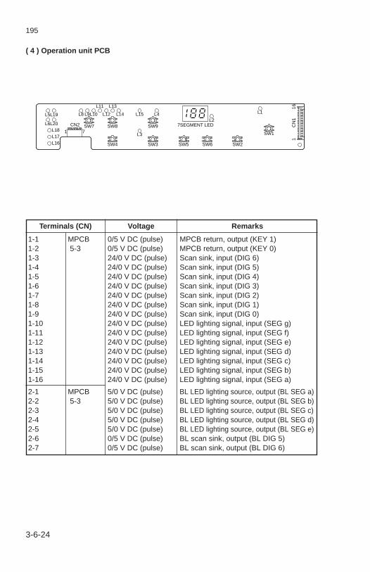
195
3-6-24
( 4 ) Operation unit PCB
Terminals (CN) Voltage Remarks
1-1 MPCB 0/5 V DC (pulse) MPCB return, output (KEY 1)1-2 5-3 0/5 V DC (pulse) MPCB return, output (KEY 0)1-3 24/0 V DC (pulse) Scan sink, input (DIG 6)1-4 24/0 V DC (pulse) Scan sink, input (DIG 5)1-5 24/0 V DC (pulse) Scan sink, input (DIG 4)1-6 24/0 V DC (pulse) Scan sink, input (DIG 3)1-7 24/0 V DC (pulse) Scan sink, input (DIG 2)1-8 24/0 V DC (pulse) Scan sink, input (DIG 1)1-9 24/0 V DC (pulse) Scan sink, input (DIG 0)1-10 24/0 V DC (pulse) LED lighting signal, input (SEG g)1-11 24/0 V DC (pulse) LED lighting signal, input (SEG f)1-12 24/0 V DC (pulse) LED lighting signal, input (SEG e)1-13 24/0 V DC (pulse) LED lighting signal, input (SEG d)1-14 24/0 V DC (pulse) LED lighting signal, input (SEG c)1-15 24/0 V DC (pulse) LED lighting signal, input (SEG b)1-16 24/0 V DC (pulse) LED lighting signal, input (SEG a)
2-1 MPCB 5/0 V DC (pulse) BL LED lighting source, output (BL SEG a)2-2 5-3 5/0 V DC (pulse) BL LED lighting source, output (BL SEG b)2-3 5/0 V DC (pulse) BL LED lighting source, output (BL SEG c)2-4 5/0 V DC (pulse) BL LED lighting source, output (BL SEG d)2-5 5/0 V DC (pulse) BL LED lighting source, output (BL SEG e)2-6 0/5 V DC (pulse) BL scan sink, output (BL DIG 5)2-7 0/5 V DC (pulse) BL scan sink, output (BL DIG 6)
L5 L8 L9
SW7CN2
1 7SW8 SW9
SW4 SW3 SW5 SW6 SW2
SW1
L10
L11
L12
L13
L14 L15 L4L2
7SEGMENT LED
L1
161
CN
1
L3
L19
L6L18L17L16
L20
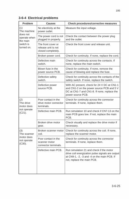
195
3-6-25
No electricity at thepower outlet.
The power cord is notplugged in properly.
The front cover orrelease unit is notclosed completely.
Broken power cord.
Defective mainswitch.
Blown fuse in thepower source PCB.
Defective safetyswitch.
Defective powersource PCB.
Poor contact in thedrive motor connectorterminals.
Defective main PCB.
Broken drive motorgear.
Broken scanner motorcoil.
Poor contact in thescanner motorconnector terminals.
Defective main PCB.
3-6-4 Electrical problems
Measure the input voltage.
Check the contact between the power plugand the outlet.
Check the front cover and release unit.
Check for continuity. If none, replace the cord.
Check for continuity across the contacts. Ifnone, replace the main switch.
Check for continuity. If none, remove thecause of blowing and replace the fuse.
Check for continuity across the contacts of thesafety switch. If none, replace the switch.
With AC present, check for 24 V DC at CN1-1and CN1-2 on the power source PCB and 5 VDC at CN1-7 and CN1-8. If none, replace thepower source PCB.
Check for continuity across the connectorterminals. If none, replace them.
Run simulation 10 and check if CN7-13 on themain PCB goes low. If not, replace the mainPCB.
Check visually and replace the drive motor ifnecessary.
Check for continuity across the coil. If none,replace the scanner motor.
Check for continuity across the connectorterminals. If none, replace them.
Run simulation 21 and check if the motordrive coil energization pulse signals are outputat CN9-1, -2, -3 and -4 on the main PCB. Ifnot, replace the main PCB.
Problem Causes Check procedures/corrective measures
(1)The machinedoes notoperate whenthe mainswitch isturned on.
(2)The drivemotor doesnot operate(C21).
(3)The scannermotor doesnot operate(C30).

195
3-6-26
Broken lens motorcoil.
Poor contact in thelens motor connectorterminals.
Defective main PCB.
Broken mirror motorcoil.
Poor contact in themirror motorconnector terminals.
Defective main PCB.
Broken toner feedmotor coil.
Poor contact in thetoner feed motorconnector terminals.
Defective main PCB.
Broken optical sectionfan motor coil.
Poor contact in theoptical section fanmotor connectorterminals.
Defective main PCB.
Problem Causes Check procedures/corrective measures
Check for continuity across the coil. If none,replace the lens motor.
Check for continuity across the connectorterminals. If none, replace them.
Run simulation 23 and check if the motordrive coil energization pulse signals are outputat CN11-1, -2, -3 and -5 on the main PCB. Ifnot, replace the main PCB.
Check for continuity across the coil. If none,replace the mirror motor.
Check for continuity across the connectorterminals. If none, replace them.
Run simulation 23 and check if the motordrive coil energization pulse signals are outputat CN11-6, -7, -8 and -10 on the main PCB. Ifnot, replace the main PCB.
Check for continuity across the coil. If none,replace the toner feed motor coil.
Check for continuity across the connectorterminals. If none, replace them.
Run simulation 10 and check if CN8-1 on themain PCB goes low. If not, replace the mainPCB.
Check for continuity across the coil. If none,replace the optical section fan motor.
Check for continuity across the connectorterminals. If none, replace them.
Run simulation 20 and check if CN13-2 on themain PCB goes low. If not, replace the mainPCB.
(4)The lensmotor doesnot operate(C41).
(5)The mirrormotor doesnot operate(C42).
(6)The tonerfeed motordoes notoperate.
(7)The opticalsection fanmotor doesnot operate.

195
3-6-27
Broken fixing unit fanmotor coil.
Poor contact in thefixing unit fan motorconnector terminals.
Defective main PCB.
Broken internalcooling fan motor coil.
Poor contact in theinternal cooling fanmotor connectorterminals.
Defective main PCB.
Broken paper feedclutch coil.
Poor contact in thepaper feed clutchconnector terminals.
Defective main PCB.
Broken registrationclutch coil.
Poor contact in theregistration clutchconnector terminals.
Defective main PCB.
Problem Causes Check procedures/corrective measures
(8)The fixing unitfan motordoes notoperate.
(9)The internalcooling fanmotor doesnot operate.
(10)The paperfeed clutchdoes notoperate.
(11)Theregistrationclutch doesnot operate.
Check for continuity across the coil. If none,replace the fixing unit fan motor.
Check for continuity across the connectorterminals. If none, replace them.
Run simulation 10 and check if CN7-14 on themain PCB goes low. If not, replace the mainPCB.
Check for continuity across the coil. If none,replace the internal cooling fan motor.
Check for continuity across the connectorterminals. If none, replace them.
Run simulation 10 and check if CN14-2 on themain PCB goes low. If not, replace the mainPCB.
Check for continuity across the coil. If none,replace the paper feed clutch.
Check for continuity across the connectorterminals. If none, replace them.
Run simulation 02 and check if CN7-6 on themain PCB goes low. If not, replace the mainPCB.
Check for continuity across the coil. If none,replace the registration clutch.
Check for continuity across the connectorterminals. If none, replace them.
Run simulation 02 and check if CN7-7 on themain PCB goes low. If not, replace the mainPCB.

195
3-6-28
Check for continuity. If none, replace thehalogen lamp (see page 3-3-16).
See page 3-6-4.
If the HL CONT (PWM) signal is alwaysoutput from CN7-10 on the main PCB, replacethe main PCB.
If the halogen lamp does not turn off when HLCONT (PWM) is not output to CN4-5 on theAVR PCB, replace the AVR PCB.
Check for one-way continuity across all theLEDs comprising the cleaning lamp. If none,replace the cleaning lamp.
Check for continuity across the connectorterminals. If none, replace them.
Run simulation 10 and check if CN7-4 on themain PCB goes low. If not, replace the mainPCB.
Check for continuity. If none, replace the fixingheater (see page 3-3-62).
Check for continuity across the thermostat. Ifnone, remove the cause of blowing andreplace the fixing unit thermostat.
Measure the resistance. If it is ∞Ω, replace thefixing unit thermistor.
Check visually and clean the thermistorsensor part.
If the fixing heater stays on with CN4-4 on theAVR PCB high, replace the AVR PCB.
If CN7-11 on the main PCB is always low,replace the main PCB.
Broken halogen lampfilament.
Optical sectionthermostat triggered.
Poor contact in theAVR PCB connectorterminals.
Defective main PCB.
Defective AVR PCB.
Defective main PCB.
Defective AVR PCB.
Defective cleaninglamp.
Poor contact in thecleaning lampconnector terminals.
Defective main PCB.
Broken fixing heaterwire.
Fixing unit thermostat1 or 2 triggered.
Broken fixing unitthermistor.
Dirty sensor part ofthe fixing unitthermistor.
Defective AVR PCB.
Defective main PCB.
Problem Causes Check procedures/corrective measures
(12)The halogenlamp does notlight.
(13)The halogenlamp does notturn off.
(14)The cleaninglamp does notlight.
(15)The fixingheater doesnot turn on(C61, C63).
(16)The fixingheater doesnot turn off(fixing unitthermostattriggered,C64).

195
3-6-29
Check visually and replace the main chargerwire if it is broken (see page 3-3-13).
See page 3-6-3.
Check visually and replace the transfercharger wire if it is broken (see page 3-3-55).
See page 3-6-3.
Check the developing bias wire for poorcontact.
Check for continuity across the connectorterminals. If none, replace them.
Run simulation 10. If no developing bias isoutput while CN1-3 on the high-voltagetransformer PCB goes low, replace the high-voltage transformer PCB.
Run simulation 10 and check if CN8-5 on themain PCB goes low. If not, replace the mainPCB.
Broken main chargerwire.
Leaking main chargerhousing.
Poor contact in thehigh-voltagetransformer PCBconnector terminals.
Defective main PCB.
Defective high-voltagetransformer PCB.
Broken transfercharger wire.
Leaking transfercharger housing.
Poor contact in thehigh-voltagetransformer PCBconnector terminals.
Defective main PCB.
Defective high-voltagetransformer PCB.
Poor contact in thedeveloping bias wire.
Poor contact in thehigh-voltagetransformer PCBconnector terminals.
Defective high-voltagetransformer PCB.
Defective main PCB.
Problem Causes Check procedures/corrective measures
(17)Main chargingdoes not takeplace (C50).
(18)Transfercharging doesnot take place(C50).
(19)Nodevelopingbias is output.

195
3-6-30
A piece of paper tornfrom copy paper iscaught around theregistration or ejectswitch.
Defective registrationswitch.
Defective eject switch.
Wiring is broken,shorted or makespoor contact.
Noise.
Problem Causes Check procedures/corrective measures
(20)A paper jamis indicated assoon as themain switch isturned on.
(21)Others.
Check visually and remove, if any.
With 5 V DC present at CN5-1 on the AVRPCB, if CN5-2 on the AVR PCB remains lowwhen the registration switch is turned on andoff, replace the registration switch.
With 5 V DC present at CN11-1 on the AVRPCB, if CN11-3 on the AVR PCB remains lowwhen the eject switch is turned on and off,replace the eject switch.
Check for continuity. If none, repair.
Locate the source of noise and remove.

195
3-6-31
Check if the surfaces of paper feedpulleys A & B, feed roller and pulleyare dirty with paper powder.
Electrical problem with the paper feedclutch.
Check if the surfaces of the feed rollerand pulley, right and left registrationrollers are dirty with paper powder.
Electrical problem with the registrationclutch.
Check if the front or rear claws insidethe paper drawer are deformed.
Check if the springs inside the paperdrawer are deformed.
Check if the scanner wires are loose.
Electrical problem with the scannermotor.
Check if the front or rear claws insidethe paper drawer are deformed.
Check if the paper is curled.
Check if the paper is extremely curled.
Check if the front or rear claws insidethe paper drawer are deformed.
Check if the springs in the paperdrawer are deformed.
Check if the press roller is extremelydirty or deformed.
Check if the heat roller separationclaws are extremely dirty or deformed.
Check if the developing unit isextremely dirty.
3-6-5 Mechanical problems
Clean with isopropyl alcohol.
See page 3-6-27.
Clean with isopropyl alcohol.
See page 3-6-27.
Remedy if deformed.
Remedy or replace ifdeformed.
Reinstall the scanner wires(see page 3-3-19).
See page 3-6-25.
Remedy if deformed.
Change the paper.
Change the paper.
Remedy if deformed.
Remedy if deformed.
Clean or replace the pressroller (see page 3-3-67).
Clean or replace the heatroller separation claws (seepage 3-3-71).
Clean the developing unit.
Problem Causes/check procedures Corrective measure
(1)No primarypaper feed.
(2)No secondarypaper feed.
(3)Skewed paperfeed.
(4)The scannerdoes not travel.
(5)Multiple sheetsof paper are fedat one time.
(6)Paper jams.
(7)Toner drops onthe paperconveying path.

195
3-6-32
Problem Causes/check procedures Corrective measure
(8)Abnormal noiseis heard.
Check if the rollers and gears operatesmoothly.
Check if the paper feed clutch andregistration clutch are installedcorrectly.
Grease the bushings andgears.
Remedy.

195
3-7 AppendixesTiming chart No. 1 ......................................................................................... 3-7-1Timing chart No. 2 ......................................................................................... 3-7-2Timing chart No. 3 ......................................................................................... 3-7-3Power source PCB ........................................................................................ 3-7-4AVR PCB ...................................................................................................... 3-7-5Operation unit PCB ....................................................................................... 3-7-6Main PCB ...................................................................................................... 3-7-7Connection diagram ...................................................................................... 3-7-8Wiring diagram .............................................................................................. 3-7-9

AA A
A
AA A
A
E
E E
E
E
E E
E
EA
EA
DC-1460 S/M (MCA,MCE)
195
A B C D E F G H I J
A B C D E F G H I J
1
2
3
4
5
6
7
8
1
2
3
4
5
6
7
8
Timing chart No. 1 The main switch is turned on when the fixing temperature (as measured by the fixing unit thermistor) is highe r than 12 °C/53.6°F and the machine internal temperature (as meassured by the drum thermistor) is higher than 15 °C/59°F
3-7-1
185°C/365°F
Fix
ing
tem
pera
ture
175°C/347°F
160°C/320°F
80°C/176°F
CN7-11
CN8-5
CN7-13
Copy start indicator
CN7-14
CN2-1 - CN2-7
CN8-4
H
DB
DM
FFM
BL
HV
200 ms
1 s
Fast
All off All on All off
29 s*
1 s
2 s
50 ms
285 ms
10 s
200 ms
MS
W: O
n
* If, when the main switch is turned onFTH temperature ≥ 10°C/50°F and ambient temperature ≥ 15°C/59°F: 29 sFTH temperature < 10°C/50°F or ambient temperature < 15°C/59°F: 44 sFTH temperature ≥ 80°C/176°F: 5 s

AA A A
A
AA A A
A
E
E E E
E
E
E E E
E
DC-1460 S/M (MCA,MCE)
195
A B C D E F G H I J
A B C D E F G H I J
1
2
3
4
5
6
7
8
1
2
3
4
5
6
7
8
Timing chart No. 2 A single copy (70% magnification ratio, bypass feed, A4R/8 1/2" × 14" paper)
3-7-2
Print key
RSW
ESW
HPSW
SM FWD
SM REV
DM
PFCL
RCL
DB
HL
HV
BL
FFM
OPFM
H (Fixing temp.)
TC
CN7-5
CN7-9
CN10-2
CN9-1 - CN9-4
CN9-1 - CN9-4
CN7-13
CN7-6
CN7-7
CN8-5
CN7-10
CN8-4
CN2-1 - CN2-7
CN7-14
CN13-2
CN3-2
RS
W: O
n
RS
W: O
ff
HP
SW
: On
ES
W: O
ff
Inpu
tO
utpu
t
100 ms
100 ms
500 ms min
2845 P
198 ms max.
65 ms 5 P
100 ms
200 ms
330 ms246 P (SIM58)
50 ms
127 P (SIM54)All on
190 ms(SIM59)
All on
Side erasure 285 ms All off
Slow SlowFast
High-level control
300 ms
3000 ms
384 ms

AA A
A
AA A
A
E
E E
E
E
E E
E
EA
EA
DC-1460 S/M (MCA,MCE)
195
A B C D E F G H I J
A B C D E F G H I J
1
2
3
4
5
6
7
8
1
2
3
4
5
6
7
8
3-7-3
Timing chart No. 3 A single copy (100% magnification ratio, drawer feed, A4R/8 1/2" × 14" paper, AE)
910 P55 msmin.
198 ms max.
Print key
RSW
ESW
HPSW
SM FWD
SM REV
DM
PFCL
RCL
DB
HL
HV
BL
FFM
OPFM
H (Fixing temp.)
TC
CN7-5
CN7-9
CN10-2
CN9-1 - CN9-4
CN9-1 - CN9-4
CN7-13
CN7-6
CN7-7
CN8-5
CN7-10
CN8-4
CN2-1 - CN2-7
CN7-14
CN13-2
CN3-2
Prin
t key
: On
RS
W: O
ff
HP
SW
: On
HP
SW
: On
ES
W: O
ff
Inpu
tO
utpu
t
100 ms
100 ms
65 ms 5 P100 ms 5 P
100 ms
200 ms
330 ms246 P (SIM58)
50 ms
450 ms
127 P (SIM54)All on
190 ms(SIM59)
All on
Side erasure 285 ms
384 ms
All off
Slow SlowFast
High-level control
300 ms
2358 P
600 ms
350 ms
3000 ms

AA A A
A
AA A A
A
E
E E E
E
E
E E E
E
DC-1460 S/M (MCA,MCE)
195
A B C D E F G H I J
A B C D E F G H I J
1
2
3
4
5
6
7
8
1
2
3
4
5
6
7
8
3-7-4
Power source PCB
F1 F3 L2*TB1
IN1
TB7IN
TB8IN
1
1
L
F2TB2IN1
TB3
TB6
TB4
OUT
OUT
1
1
TB5OUT
TB9OUT1
TB10OUT1
IN
1
1
N
R1
C1
C2 C3
C8
R3
R2
C4VZ1
L1 L3
R4
D1
ZD1
R17
D3 R11
–
~
~DB1
+
C5 C6
FB2 FB3
FB1
C16 C7
FG
C12
C13
R18
+
C11
PC2
IC1
PC1
C15
C14
R15
R16
R14
+C9
C10
R9
R8 R5
R6
D2
FB
4
R7R19
R10
FB5
D4
R13
DG
Q1
S
FB101
R101 C101
D101
C102
FB102
FB201
D201 D202
PC1
+
C201
+
C202
+
IC2011 2
3 4
R10
2
R10
3
R10
4
R10
5C
103
R10
6
R11
0
R11
1
R10
9
R10
7
Q101
D10
2Z
D10
2
D20
3Z
D20
1
ZD
101
FB103
+
C10
4
PC
2
CN1
OUT1
CN1
OUT2
+24 V
CN1
OUT7
CN1
OUT8
+5 V
CN1
OUT3
CN1
OUT4
DG
CN1
OUT5
CN1
OUT6
SG
T1
* For 220 - 240 V specifications only.

AA A
A
AA A
A
E
E E
E
E
E E
E
EA
EA
DC-1460 S/M (MCA,MCE)
195
A B C D E F G H I J
A B C D E F G H I J
1
2
3
4
5
6
7
8
1
2
3
4
5
6
7
8
3-7-5
AVR PCB
+– +
–
+
+
+
+
CN12-4
R24
R19 R18
R23 R1
R3
R2C2
PC4
C3
C6
C4
C5
PC3
PC2
PC5
TRC1
TRC2
TRC3 CR3
CR1
CR2
ZDVR1
R5
R7 R8R14
R15
R22
R12
(R16A)
(R16B)
(R16C)
R13
R9
R11
R10
VR3
VR2
R4
R6Q1
Q2 HIC
D1D3D2
DB RF
C7
L
C8
C9
C10
R21
1 65 7
11
137
1
2
3
5.9
5.9–12
0 V
SS
ZERO
Flickerresistor(for 230 V specifications and optional for 240 V specifications)
+12 12
14
8
4
–12
IC
8
423
C1
PC1
PC1
PC5
PC2
PC4
R25
CN12-3CN12-2CN12-1
CN10-2CN10-1CN9-2CN9-1
CN5-3CN5-2
CN5-1CN6-1CN6-2
CN7-1CN7-2CN11-2CN11-3
CN11-1CN13-2CN13-1CN13-3CN14-2
CN14-1
FFM
PART NAMETRC3PC5CN3CR3C10R16A, C
MOUNTNOT MOUNTNOT MOUNTNOT MOUNT
MOUNTMOUNTMOUNTMOUNTMOUNTMOUNT
NOT MOUNTNOT MOUNTNOT MOUNTNOT MOUNTR23
120 V 220 - 240 V
24 VCL24 V
G (5 V)RSW
5 V24 VPFCL
24 VRCLG (5 V)ESW
5 V5 VFTH
ICFM
24 V
CN4-14CN4-13CN4-12CN4-11CN4-10CN4-9CN4-8
ZERO CROSSFlicker REM
5 VCL REM
RSWPFCL
RCL
CN4-7FTHCN4-6ESWCN4-5HL CONTCN4-4H REM
CN4-3DM ALMCN4-2DM REM
CN4-1FFM REMCN8-4CN8-3CN8-1CN8-2
DM ALMDM REM
DM G (24 V)
24 V
5 VG (5 V)
G (24 V)24 V
R17AR17B
TB1
CN2-1
CN1-1
CN1-2
CN2-3
H LIVE
HL LIVE
AC LIVE
AC COM
HL COM
CN3-4
CN3-1
TB2 H COM

AA A A
A
AA A A
A
E
E E E
E
E
E E E
E
DC-1460 S/M (MCA,MCE)
195
A B C D E F G H I J
A B C D E F G H I J
1
2
3
4
5
6
7
8
1
2
3
4
5
6
7
8
Operation unit PCB
3-7-6
CN
1-16
SE
G a
CN
1-15
SE
G b
CN
1-14
SE
G c
CN
1-13
SE
G d
CN
1-12
SE
G e
CN
1-11
SE
G f
CN
1-10
SE
G g
CN
1-9
DIG
0
CN
1-8
DIG
1
CN
1-7
DIG
2
CN
1-6
DIG
3
CN
1-5
DIG
4
CN
1-4
DIG
5
CN
1-3
DIG
6
CN
1-1
KE
Y 1
CN2-7 BL DIG 6
b1
c1
f2 b2f3
L5 L8 L9
SW7CN2
1 7SW8 SW9
SW4 SW3 SW5 SW6 SW2
SW1
L10
L11
L12
L13
L14 L15 L4L2
7SEGMENT LED
L1
161
CN
1
L3
L19
L6
L18
L17
L16
L20e3c2
b3
c3
a2
7 SEGMENT LED
a3
g2 g3
d2 d3
e2
CN2-6 BL DIG 5CN2-5 BL SEG eCN2-4 BL SEG dCN2-3 BL SEG cCN2-2 BL SEG bCN2-1 BL SEG a
CN
1-2
KE
Y 0
L1 L2 L3 L4 L5 L6D9SW9
D7SW7
D8SW8
D5SW5
D6SW6
D3SW3
D4SW4
D1SW1
D2SW2
L8 L9 L10 L11 L12 L13
L19 L20
L14
a2 b2 c2 d2 e2 f2 g2
a3 b3 c3 d3 e3 f3 g3
L15 L16 L17 L18 b1 c1

A B C D E F G H I J
A B C D E F G H I J
1
2
3
4
5
6
7
8
1
2
3
4
5
6
7
8
195
3-7-7
Main PCB 195
P G
P G
CL REM
7 12 8 1 18 11
9 3 1410 4 15
R53
C25
R52 R31
R30
C10
R32
C1
C15 C14
2 VS
AV
SB A A B B
RS
AR
EF
AR
EF
BR
SB
CN
DA
CN
DB
TdATdB
AABB
13
R54
R1
R4
IC11
OUTIN
R58
TR2
IC10
IC10
IC7
IC7DT5
DT6
R10
7
R10
8
IC7
IC10
4 3
2 1
10 11
15 14
R57
R109
DT1
R105
R15
R110
H ALARM
DT4
C B
E
C BD3
D2
P96
P95
P94
P93
P92
P91
P90
P37
P36
P35
P34
P33
P32
P31
T00
P10
3P
102
P10
1P
100
AS
TB
P16
P17
AV
SS
AN
O0
P13
1A
VR
EF
R×D
T×D
AS
CK
VS
SP
20P
21P
22P
23P
24P
25P
26P
27A
0A
1
E
CB
14 15
11 10
6 7
3 IC4
IC4
IC4
IC4
2
3 2
5 6E
CB
E
DM REM
H REM
24 V
TFM REM
TC
TC IN
Flicker resistor REM*
MSW
24 V
MHPSW
LHPSW
DEVF IN
TC IN
FFM REM
HL CONT
MM 4
MM 3
MM 1
MM 2
PFCL
RCL
PHOTO REM
HV REM
DB REM
SEG a
IC16
IC16
IC16
IC16
IC16
IC167
6
5
4
3
2
1
12
13
14
15
16
17
18
IC16
SEG b
SEG c
SEG d
SEG e
SEG f
SEG g
OPFM REM
5 V
5 V
5 V
5 V
5 V
C5 C31G (5 V)
G (5 V)
G (5 V)
G (5 V)
24 V
CN1-1
CN1-2
CN7-2
CN3-1
CN3-2
CN11-9
CN9-5
CN9-4
CN9-3
CN9-2
CN9-1
CN11-4
CN11-1
CN11-2
CN11-3
CN11-5
CN10-2
CN7-1
CN2-15
CN6-1
CN2-16
CN7-5
CN7-9
CN7-8
CN12-5
CN4-1
CN4-3
CN4-2
CN4-5
CN4-4
CN7-12
CN8-2
CN6-8
CN6-7
CN8-1
CN7-11
CN7-13
CN7-4
S
S
S
S
IC132 3
R22
R26
R51
C B
E
R106 S
S
S
S
S
S
S
S
S
281
S G
24 V
R21
R27
6 7IC13
11 10IC13
IC109 8
IC1011 10
IC10
R40
A15 R92
R94A15
_RD
R72R73R74R75R76R77R78R79R97R96R93R95R80R98R99
A0 A1 A2 A3 A4 A5 A6 A7 A8 A9A10A11A12A13A14
2022109876543
252421232
2627
1112131516171819
R71R70R69R87R88R89R90R91
D0D1D2D3D4D5D6D7
_CE_OEA0A1A2A3A4A5A6A7A8A9A10A11A12A13A14
VccVpp
Q0Q1Q2Q3Q4Q5Q6Q7
IC5
INTP1
NON MOUNT
NON MOUNT
_OC
_OC
R20
R23
IC2
IC6
33
A15
_WR
15
2 CLK
103
11
R44
R45
R46ZD
1
13 12
+
–
+
–
D0D1D2D3D4D5D6D7
D1D2D3D4D5D6D7D8
Q1Q2Q3Q4Q5Q6Q7Q8
3478
13141718
256912151619
R12
R11
R10
R9
R8
R7
R6
6 7IC7
+
24 V
24 V
24 V
24 V
C24
IC13
R59
R60
R5
D5
8 11
9
10
IC16 IC16
C12
C11 C26
C9 C30C4
IC17
C29G (24 V)
G (24 V)
G (24 V)
G (24 V)
+S
S9
9, 16
COM
1, 8
8
8
4
IC9
S
S
4, 5, 12, 13
IC3, 4, 7, 13 IC14 IC5 IC2, 6, 10, 17
+
–
3
12
+
–
+
–
5
6
C34R
104
7IC14
R62
R55
R103
C33
R64
R63
R65
R49
R56
R102
R66
R100
C18
D4
C17
R48
R61
DIG 01
1234
8765
16IC9
IC8
C16
DIG 12 15IC9
DIG 23 14IC9
DIG 34 13IC9
DIG 45 12IC9
DIG 5
DIG 6
DEV SW
SHORT
DEVF
DEVF IN
6 11IC9
7 10
14 15
IC9
S
S
807978777675747372717069686766656463626160595857565554535251
123456789
101112131415161718192021222324252627282930
A15A14
A13A12A11A10A9A8D7D6D5D4D3D2D1D0A7A6A5A4A3A2A1A0
P66_WR_RDP63P62P61P60A15A14VSSA13A12A11A10A9A8
AD7AD6AD5AD4AD3AD2AD1AD0
A7A6A5A4A3A2
RTP0RTP1RTP2RTP3RTP4RTP5RTP6RTP7ICX2X1VDDXT2P07_RESETINTP0/P00INTP1/P01INTP2/P02INTP3/P03INTP4/P04INTP5/P05P06AVDDAVREF0AN10AN11AN12AN13AN14AN15
100
99 98 97 96 95 94 93 92 91 90 89 88 87 86 85 84 83 82 81
31 32 33 34 35 36 37 38 39 40 41 42 43 44 45 46 47 48 49 50
_WR_RD
WD
R25
R24
R83
R84
R47
R39C13R42 R41
H ALARM
TNS CONT
HV ALM
DM ALM
G (5 V)
ETTH
G (5 V)
HUMSENS
5 V
AES
TNS
FTH
FSW
RSW
KEY1
KEY0
DEV-UNIT
ZERO CROSS
HPSW
LM 4
LM 3
LM 1
LM 2
24 V
SM B
SM B
SM A
SM A
24 V
S
S
SS
D1
C20
C21C3 S
S
D6
S
S
S
S
S
S
S
IC14
C27
3
2
1
C22
+
–
+
–
+
–
+
IC5
IC5
IC5
8
9
14
7
6
1
5
4
2
C23
X1
1 3
2 H ALARM_RESET
INTP 1
R43
R68R67
R81
R35
R38
R33
R82
R34
R37
R86
R13R14
R85
R36
2 3IC3
7 6IC3
10 11IC3
15 14IC3
P G
P GP G
P G
65716
+ IC6
_OC
_RESET6 2
IC6
C8
IC1
R17 C7
R18ADJ2_RES2VCCADJ1
8765
1234
WDTC
_RES1GND
C6
R16
R19
WD
1 7
S
S
S
S G
S G
S G
S G
S GS G
S G S G
S G
S G
S G
S G
S
VCCNCTESTGND
CSSKDI
DOG
S G
S G
S G
S G
S G
S G S G
S G
S G S G
S G
S G S G
S GS G
S G S G S G
P G P G
CN2-8
CN2-9
CN2-10
CN2-11
CN2-12
CN2-13
CN2-14
CN6-2
CN6-4
CN6-3
CN6-5
CN5-1 CN5-4
CN7-3
CN2-1
CN2-2
CN2-3
CN2-4
CN2-5
CN2-6
CN2-7
CN13-1
CN13-2
CN10-1
CN12-1
CN12-7
CN10-3
CN12-2
CN12-8
CN5-3CN5-2
CN8-7
CN12-4
CN6-6
CN8-6
CN12-6
P G
S G
S G
S G
S G
S G
S G
S G
CN7-6
CN7-7
CN8-3
CN8-4
CN8-5
CN12-3
CN12-9
CN7-14
CN7-10
CN11-10
CN11-8
CN11-7
CN11-6
IC12
IC15C28
* For 230 V specifications and optional for 240 V specifications.
φ
φ
φ
φ
φ
φ
φ
φ

A B C D E F G H I J
A B C D E F G H I J
1
2
3
4
5
6
7
8
1
2
3
4
5
6
7
8
195
3-7-8
Connection diagram
120 V 910 W
240 V 1040 W
3 13 2 21
987123
11
11
6- 1
9- 1
10- 110- 2
ICFM
FFM
ICFM
24 VCL CL
24 VPFCL PFCL
24 VRCL RCL
G (5 V)
G (5 V)
G (
5 V
)
G (
5 V
)
G (
5 V
)
G (
24 V
)
G (
5 V
)G
(24
V)
5 V
5 V
5 V
RSW RSW
ESW
ESW
FTH FTHN. C
5 V
SM
B
FF
M R
EM
LM
2
LM
4M
M
2M
M
1M
M
3
MM
4
LM
1LM
3
DM
RE
MD
M A
LMH
RE
M
ES
WF
TH
RC
LP
FC
LR
SW
CL
RE
M5
V
5 V
24 V
24 V
BL
SE
G a
BL
SE
G b
BL
SE
G c
BL
SE
G d
BL
SE
G e
BL
DIG
5B
L D
IG 6
24 V
GN
D (
24 V
)24
VD
M R
EM
DM
ALM
Flic
ker
RE
MZ
ER
O C
RO
SS
HL
CO
NT
SM
BS
M A
SM
A24
V
5 V
5 V
AE
S24
VM
HP
SW
HP
SW
HPSWLHPSWAESMHPSW
LHP
SW
24 V
FFM24 V
14- 114- 2
TH3
HL
H
TH2 TH1
9- 2
2
11
2
654321456789
3
1
1
3
1
1
2
2
23
12
2
1 12 2
3213 2 1
11- 211- 3
4-1
3 4
-12
4-1
1 4
-10
4-
8 4
- 7
4-
6 4
- 5
5- 2 5- 3
7- 2 7- 1
6- 2
5- 1
4-1
4
4-
3 4
- 4
10-
3
10-
110
- 2
12-
712
- 8
12-
9
12-
6
4-
9 13- 3
11- 1
13- 113- 2
1234
12-
3
12-
1
12-
412
- 5
9-
4 9
- 5
9-
2 9
- 1
9-
313
- 2
13-
1
7-
1 7
- 2
7-
3 7
- 4
7-
5 7
- 6
7-
8 7
- 9
7-1
0 7
-11
7-1
2
12-
2
331
5
7-
7
1
HV
24 V
FB
TFM
OPFM
HUMPCB
TFM
DB
MC
TC
1-
6 1
- 5
1-
4 1
- 3
1-
2 1
- 1
1-
7H
V A
LMP
HO
TO
RE
MH
V R
EM
DB
RE
MG
(24
V)
24 V
DE
V.U
NIT
DE
V.U
NIT
DE
V S
W
DE
V S
W
DE
VF
SH
OR
T24
V
TN
ST
NS
CO
NT
G (
24 V
)
24 V
24 V
MS
W
TC
24 V
5 V
G (
5 V
)H
UM
SE
NS
G (
5 V
)E
TT
H
OP
FM
RE
M
TF
M R
EM
2- 12- 2
HVTPCB
TNS
TC
DEVFfor 120 V, 220 V and240 V specifications Dev.bias
TB
2
FU
SE
TB
1
TB 9
TB
8T
B7
TB
6
TB
5
1-3
1-4
1-2
1-1
2
4-
2 4
- 1
8-
1 8
- 2
8-
3 8
- 4
135 23
1-81-61-4
1
54321
454
1-2
12-412-312-212-1
5 V
G (5 V)G (24 V)24 V
1- 2
1- 1
Flicker resistor(for 230 V specifications and optional for 240 V specifications)
3- 1
3- 4
2- 1
2- 3
HL
LIV
E
HL
CO
M H LIVE
H COM
1-7
1-5
1-3
1-1
TB1
120 VFUSE250 V/15 A
120 VFUSE250 V/15 A
FUSE250 V/8 A220 - 240 V
220 - 240 VFUSE250 V/8 A
MS
W
SSW
DHBA
21
TB
4
120 V220 - 240 V
TB
3
11-
911
-10
11-
8
7-1
3 7
-14
NEUTRAL
LIVE
CORE(for 220 - 240 V specifications only)
optional for120 V specifications
TB2
11-
5
11-
211
- 1
11-
3
5-
3
5-
1 5
- 2
12345
5-
4
3- 2
3- 1
6- 4
6- 3
6- 6
6- 5
6- 8
6- 7
8- 6
8- 7
8- 4
8- 5
8- 2
8- 1
4- 1
4- 2
4- 3
4- 4
4- 5
8- 3
6- 1
6- 2
6- 1
6- 2
1- 2
1- 1
11-
711
- 6
11-
4
3 10
43214321
321
321
321
3
1342
9874 5 6 12111 21 2
BA
2-162-15
1-16SEG a
SEG b
SEG c
SEG d
SEG e
SEG f
SEG g
DIG 0
DIG 1
DIG 2
DIG 3
DIG 4
DIG 5
DIG 6
KEY 0
KEY 1
1-151-141-131-121-111-10
1- 81- 71- 61- 51- 41- 31- 21- 1
1- 9
2-142-132-122-112-102- 92- 8
2- 62- 52- 42- 32- 22- 1
2- 1
2- 7
2- 7
2- 6
2- 5
2- 4
2- 3
2- 2
NF
PSPCB
MPCB
AVRPCB
SM
DM
LMBL
OPCB
MM
TB10
TC
DS
W
321
321
321
TC
DS
W
321
321
321
TC
DS
W
φ φφ φ φ φ φφ
2
1
1
2
195-1

A B C D E F G H I J
A B C D E F G H I J
1
2
3
4
5
6
7
8
1
2
3
4
5
6
7
8
195
3-7-9
Wiring diagram
120
V
220
- 24
0 V
INLE
T
HUMPCB
GY
C11
-6G
Y C
11-7
GY
C11
-8G
Y C
11-9
GY
C11
-10
MM
5 VG (5 V)HUMSENSG (5 V)ETTH
54321
RD P1-5GN P1-6
C17
C30
C1
(CN
1)
24 VMSW
12
2 1 3 24 V
4
5 4 3 2 1
SEG aSEG bSEG cSEG dSEG eSEG fSEG gDIG 0DIG 1DIG 2DIG 3DIG 4DIG 5DIG 6KEY 0KEY 1
GY C14-16GY C14-15GY C14-14GY C14-13GY C14-12GY C14-11GY C14-10GY C14-9GY C14-8GY C14-7GY C14-6GY C14-5GY C14-4GY C14-3GY C14-2GY C14-1
C2
(CN
2)
123456789
10111213141516
TC
C3
(CN
3) BKBK24 V
TC12
OE
C25
-3G
N C
25-2
BE
C25
-1
LM
2LM
1
LM
324
VLM
4
MM
2
MM
1
MM
3
24 V
MM
4
1 2 3 4 5 6 7 8 9
GY
C28
-9G
Y C
28-8
GY
C28
-7G
Y C
28-6
GY
C28
-5G
Y C
28-4
GY
C28
-3G
Y C
28-2
GY
C28
-1
GY
C26
-5G
Y C
26-4
GY
C26
-3G
Y C
26-2
GY
C26
-1G
Y C
30-5
GY
C30
-4G
Y C
30-3
GY
C30
-2G
Y C
30-1
1 2 3 4 5 6 7 8 9 101 2 3
OPFM
52 1
6 C26C27
12345
SM BSM BSM ASM A24 V
1 2
32
RD
RD
C54
C12 (CN12)C11 (CN11)
C10 (CN10)
5 V
HP
SW
G (
5 V
)
MPCB
YWBERDBNWE
1
C9
(CN
9)
RD
C18
-1B
E C
18-3
BE
C18
-5O
E C
18-7
GY
C17
-5G
Y C
17-4
GY
C17
-3G
Y C
17-2
GY
C17
-1
GY
C54
-1G
Y C
20-2
,3P
E C
20-6
PE
C20
-7R
D C
20-8
BE
C20
-9P
K C
20-1
0G
N C
20-1
1
C6 (CN6)
C5 (CN5) C4 (CN4)
1 2 3 4 5 6 7 8 1 2 3 4 1 2 3 4 5
DE
V. U
NIT
DE
V S
WD
EV
FS
HO
RT
24 V
G (
24 V
)T
NS
TN
S C
ON
T
24 V
G (
24 V
)G
(5
V)
5 V
5 V
G (
5 V
)H
UM
SE
NS
G (
5 V
)E
TT
H
TFM REMHV ALMPHOTO REMHV REMDB REMG (24 V)24 V
C13 (CN13)
C8
(CN
8)
1234567
ZERO CROSSFlicker REM5 VCL REMRSWPFCLRCLFTHESWHL CONTH REMDM ALMDM REMFFM
GY C22-14GY C22-13GY C22-12GY C22-11GY C22-10GY C22-9GY C22-8GY C22-7GY C22-6GY C22-5GY C22-4GY C22-3GY C22-2GY C22-1
GY C23-7GY C23-6GY C23-5GY C23-4GY C23-3GY C23-2GY C23-1
123456789
1011121314
C7
(CN
7)
BK P1-2
BK P1-1
WE
BK
BK P2BK P3
MSW
LIVELIVE
24 VMSW
12456
P1
Wire colorBLACKBROWNYELLOWGREENBLUE
WHITEPINKRED
ORANGELIGHT BLUE
PURPLEGRAY
GREEN/YELLOWRED/WHITE
BKBNYWGNBEWEPKRDOELBPEGY
GN/YWRD/WE
Symbol
TB1TB
10
P5
P4
P2
24 V
24 V
G (
24 V
)G
(24
V)
G (
5 V
)G
(5
V)
5 V
5 V
1 2 3 4 5 6 7 8
BK
C35
-1
P12P11
RD
C5-
1R
D C
45-1
BE
C5-
2B
E C
45-2
BE
C5-
3B
E C
45-3
OE
C5-
4O
E C
45-4
TB
9
CO
M
C18 (CN1)
WE
C35
-3W
E C
56-2
BK
C56
-1
LIV
E
COM
LIVE
LIVE
LIVE
TB4
TB3
TB2
ICFM
C56
BK P12BK P11
RD C53-1BK C53-2
GY C55-2GY C55-3
GY C6-1GY C20-11
23
BK
BK
40 W
10
Ω
40 W
10
Ω
*1 For 220 V/60 Hz and 230 V specifications.*2 For 120 V, 220 V/50 Hz, 220 V/60 Hz and 240 V specifications.*3 For 120 V, 220 V and 240 V specifications.
CO
RE
(for
220
- 2
40 V
spe
cific
atio
ns o
nly)
40 W
10
ΩFU
SE
TB
8
TB
7
PSPCB
CO
M
CO
M
P8
P7
P6
LIV
E
LIV
E
P9
TB
6
TB
5
P101A1B2A2B
1234
BK P6BK P8WE P7WE P9
SSW
GY
C12
-9G
Y C
12-8
GY
C12
-7G
Y C
12-6
GY
C12
-5G
Y C
12-4
GY
C12
-3G
Y C
12-2
GY
C12
-1
C29C28
GY
C11
-5G
Y C
11-4
GY
C11
-3G
Y C
11-2
GY
C11
-1
56789654321
345612344321987
TFMX1
C23 (CN1)
C24 (CN2)
TFM REMHV ALMPHOTO REMHV REMDB REMG (24 V)24 VHVTPCB
24 VTFM
P16
P15
GY C29-3GY C29-2GY C29-1
7654321
12
21C46
BK
C36
-1W
E C
36-2
C22 (CN4)
WE
C49
-1
WE
C46
-2
TB
1
1413121110987654321
ZERO CROSSFlicker REM5 VCL REMRSWPFCLRCLFTHESWHL CONTH REMDM ALMDM REMFFM
3 2 1
MH
PS
W
WE
P11
BK
P12
C32MHPSWG (5 V)5 V
1 2 3
BK
C46
-1
123
12
24 VICFM
RDBK
C53 (CN14)
YW C9-1BE C9-2RD C9-3BN C9-4WE C9-5
P13
C45 (CN12)
C39 (CN6)C38 (CN5)
C36 (CN2)C35 (CN1)
RD
RD P17RD
BK
C43
-2R
D C
43-1
BE
C40
-2B
E C
40-1
BE
C39
-2B
E C
39-1
YW C20-12
PFCLRCLFFM
DMO
E C
10-1
GN
C10
-2B
E C
10-3
3 2 1
C25
C16
SM
HPSW
GY
C41
-4G
Y C
41-3
GY
C41
-2G
Y C
41-1
1 2 3 4
5 V
HP
SW
G (
5 V
)
WE
C50
-1T
B2
GN C19-2OE C19-1
BK
BK
123
FTH5 V
1 2 3 4
GY C51-2GY C51-1
C37 (CN3)
GY C16-4GY C16-3GY C16-2GY C16-1
OE C47-1BE C47-2GN C47-3
RDBK
P14
24 VCL
24 VFFM
G (24 V)24 VDM REMDM ALM
1234
12
5 VG (5 V)ESW
123
12
C44
(C
N11
)C
43 (
CN
10)
C42
(C
N9)
C40 (CN7)
RD C29-4GN C29-5BE C29-6
C21TCDSW
BK
321
BK
C37
-4
1211
BK
C46
-1T
H3
HL D
EV
SW
DE
V S
WG
Y C
54-1
GY
C54
-24
OE
YW
BE
RE
C18
-2B
E C
18-4
BE
C18
-6O
E C
18-8
1 2 3 4
C33123
BE
BE
1 2 1 2 3
24 VAESG (24 V)A
ES
RD
BE
PK
GN
RD
BE
PK
GN
YW
DE
V. U
NIT
DE
V S
W
GY
GY
*1 *2
DEVF*3
5432131
GY
GY
9876
DE
V. U
NIT
DE
V S
W
DE
VF
SH
OR
T24
VG
(24
V)
TN
ST
NS
CO
NT
DB
TNS
21
C14 (CN1)
LHPSWG (5 V)5 V
DEVELOPING UNIT
Dev. bias
C34
GY
C2-
16G
Y C
2-15
GY
C2-
14G
Y C
2-13
GY
C2-
12G
Y C
2-11
GY
C2-
10G
Y C
2-9
GY
C2-
8G
Y C
2-7
GY
C2-
6G
Y C
2-5
GY
C2-
4G
Y C
2-3
GY
C2-
2G
Y C
2-1
LHP
SW
123
KE
Y 1
KE
Y 0
DIG
6D
IG 5
DIG
4D
IG 3
DIG
2D
IG 1
DIG
0S
EG
gS
EG
fS
EG
eS
EG
dS
EG
cS
EG
bS
EG
a
BE
BE
1 2
BK
BK
21
CLEANING UNITTC
RS
W
BL
2 1FB
MC
GY
C42
-1G
Y C
42-2
RD
P16
RD
P15
RD
P15
P17C52C51
3 1211C49C19
FT
H
TH
2
1 2 3
5 V
G (
5 V
)E
SW
WE
WE
BK
BK
C50
C15 (CN2)
BL
SE
G a
BL
SE
G b
BL
SE
G c
BL
SE
G d
BL
SE
G e
BL
DIG
5B
L D
IG 6
WE
WE
WE
WE
WE
WE
WE
5 4 3 2 1
ES
W
FIXING UNIT
WE
H
BK
P10
-1
BK
P10
-2
WE
P10
-3
WE
P10
-4
BK
C37
-1
GY
C34
-1G
Y C
34-2
GY
C34
-3B
E C
33-3
GN
C33
-2R
D C
33-1
GY
C32
-1G
Y C
32-2
GY
C32
-3
GY
C31
-1G
Y C
31-2
GY
C31
-3G
Y C
31-4
GY
C31
-5
DM
ALM
DM
RE
M24
VG
(24
V)
H L
IVE
AC
LIV
E IN
AC
CO
M IN
HL
CO
M
HL
LIV
E
BK
C46
-2
C20
C55
C46
(C
N13
)
LIV
E
CO
M
PE
C6-
3P
E C
6-4
RD
C6-
5B
E C
6-6
PK
C6-
7G
N C
6-8
YW
X1
GY
C6-
1G
Y C
6-2
GY
C6-
2
GY
C6-
1
1 2 3 4 5 6 7 8 9 10 11 12 13 14 15 16
GN
C46
-1O
E C
46-2
WE
P14
WE
P13
BK
GN
GY C4-1GY C4-2GY C4-3GY C4-4GY C4-5
1 2 3 4 5 6 7
GY C8-1GY C8-2GY C8-3GY C8-4GY C8-5GY C8-6GY C8-7
GY C7-1GY C7-2GY C7-3GY C7-4GY C7-5GY C7-6GY C7-7GY C7-8GY C7-9GY C7-10GY C7-11GY C7-12GY C7-13GY C7-14
10
GY C29-9GY C29-8GY C29-7
3
P3 RD C1-1GN C1-2
24 V
OP
FM
RE
M
5 V
G (
5 V
)M
HP
SW
24 V
AE
SG
(24
V)
5 V
G (
5 V
)LH
PS
W
CLC
48
TH
1
GY
C27
-2G
Y C
27-3
GY
C27
-4G
Y C
27-5
GY
C27
-6
OPCB
LM
H C
OM
DB
FB
AVRPCB
HV
12
BE
C56
-1B
E C
56-2
24 V
PF
CL
24 V
RC
L
C41
(C
N8)
5 V
RS
WG
(5
V)
24 V
G (
24 V
)G
(5
V)
5 V
Flicker resistorfor 230 V specificationsand optional for 240 Vspecifications
LM
2LM
1
LM
324
VLM
4
Opt
iona
l for
120
Vsp
ecifi
catio
ns
DH
φ φ φ φ φ φ φ φ
φ φ φ φ
φ φ φ φ
C47
OE
BE
GN
OE
C44
-1B
E C
44-2
GN
C44
-3
1 32

©1997 MITA INDUSTRIAL CO., LTD.MITA and are registered trademarks of MITA INDUSTRIAL CO., LTD.
MITA COPYSTAR AMERICA, INC.Headquarters:225 Sand Road, P.O. Box 40008Fairfield, New Jersey 07004-0008TEL : (973) 808-8444FAX : (973) 882-6000
New York Show Room:149 West 51st street,New York, NY 10019TEL : (212) 554-2679FAX : (212) 554-2625
Northeastern Region:225 Sand Road, P.O. Box 40008Fairfield, New Jersey 07004-0008TEL : (973) 808-8444FAX : (973) 882-4401
Midwestern Region:225 Spring Lake Drive,Itasca, Illinois 60143TEL : (630) 250-7447FAX : (630) 250-8787
Western Region:14101 Alton Parkway,P.O.Box 57006, Irvine,California 92618-7006TEL : (714) 457-9000FAX : (714) 457-9119
Southeastern Region:1500 Oakbrook Drive,Norcross, Georgia 30093TEL : (770) 729-9786FAX : (770) 729-9873
Southwestern Region:2825 West Story Road,Irving, Texas 75038-5299TEL : (972) 550-8987FAX : (972) 570-4704
Dallas Parts Distribution Center& National Training Center:2825 West Story Road,Irving, Texas 75038-5299TEL : (972) 659-0055FAX : (972) 570-5816
MITA COPYSTAR CANADA, LTD.6120 Kestrel Road,Mississauga, Ontario L5T 1S8TEL : (905) 670-4425FAX : (905) 670-8116
MITA COPYSTAR MEXICO, S.A. DE C.V.Av. 16 de Septiembre #407Col. Santa Inés,Delegación AzcapotzalcoMéxico, D.F. C.P. 02130TEL : 3-83-27-41FAX : 3-83-78-04
Printed in U.S.A.