dcc user gateway interface specification - main document€¦ · dcc user gateway interface design...
TRANSCRIPT

DCC User Gateway Interface Design Specification
Main Document
Page 1 of 134
12/09/2014 DCC PUBLIC
DCC User Gateway Interface Design Specification
Main Document
Author: DCC
Version: v0.8 Draft
Date: 12th
September 2014

DCC User Gateway Interface Design Specification
Main Document
Page 2 of 134
12/09/2014 DCC PUBLIC
Contents
1 Introduction ..................................................................................................................................... 8
1.1 Document Purpose .................................................................................................................. 8
1.2 Document Scope ...................................................................................................................... 8
1.3 Document Structure ................................................................................................................. 8
1.4 Referenced Documents ........................................................................................................... 9
2 Overview of Interface ................................................................................................................... 11
2.1 Context ................................................................................................................................... 11
2.2 Service Request Processing .................................................................................................. 11
2.3 Modes of Operation ................................................................................................................ 12
2.3.1 Transform ................................................................................................................. 13
2.3.2 On Demand .............................................................................................................. 13
2.3.3 DCC Only ................................................................................................................. 13
2.3.4 Future Dated (Device) .............................................................................................. 13
2.3.5 Future Dated (DSP) .................................................................................................. 13
2.3.6 Meter Scheduled ...................................................................................................... 13
2.3.7 DSP Scheduled ........................................................................................................ 14
2.3.8 Device Alerts ............................................................................................................ 14
2.3.9 DCC Alerts ............................................................................................................... 14
2.3.10 Firmware Distribution................................................................................................ 14
2.3.11 Change of Supplier ................................................................................................... 15
2.4 Web Services ......................................................................................................................... 16
2.5 Use of the DCC User Gateway Network ................................................................................ 18
3 Command Variant ......................................................................................................................... 19
3.1 Interface Message Types ....................................................................................................... 19
3.2 Command Variant Types ....................................................................................................... 20
3.3 CV = 1 (Non-Critical Service Request – Send Command over SM WAN) ............................. 22
3.4 CV = 2 (Non-Critical Service Request – Return Command for Local Delivery) ...................... 23
3.5 CV = 3 (Non-Critical Service Request – Send Command over SM WAN and Return for Local
Delivery) ............................................................................................................................................. 24
3.6 CV = 4 (Transform Service Request – Return Pre-Command) .............................................. 25
3.7 CV = 5 (Signed Pre-command – Send Command over SM WAN) ......................................... 26

DCC User Gateway Interface Design Specification
Main Document
Page 3 of 134
12/09/2014 DCC PUBLIC
3.8 CV = 6 (Signed Pre-command – Return Command for Local Delivery) ................................. 27
3.9 CV = 7 (Signed Pre-command – Send Command over SM WAN and Return for Local
Delivery) ............................................................................................................................................. 28
3.10 CV = 8 (DCC Only Service Request – Service Response Returned) ..................................... 29
3.11 Access Control Failure ........................................................................................................... 30
3.11.1 CV = 1, 2, 3, 4 or 8 Access Control Failure .............................................................. 30
3.11.2 CV = 5, 6 or 7 Access Control Failure ...................................................................... 31
3.12 Command Variant / Mode of Operation and Web Services .................................................... 32
4 Request and Response IDs ......................................................................................................... 33
4.1 Send Command and Receive Response (KRP) – Command Response ............................... 36
4.2 Send Command and Receive Response (KRP) – FDEDA .................................................... 37
4.3 Send Command and Receive Response (URP) .................................................................... 38
4.4 Send Command and Receive Response (URP) – FDEDA .................................................... 39
4.5 Return Command for Local Delivery (KRP) ........................................................................... 40
4.6 Return Command for Local Delivery (URP) ........................................................................... 40
4.7 Send Command and Return for Local Delivery (KRP) ........................................................... 41
4.8 Send Command and Return for Local Delivery (URP) ........................................................... 41
4.9 Transform Command (KRP) .................................................................................................. 42
4.10 Transformed Send Command and Receive Response (KRP) ............................................... 42
4.11 Transformed Send Command and Receive Response (KRP) – FDEDA ............................... 43
4.12 Transform and Return Command for Local Delivery (KRP) ................................................... 44
4.13 Transformed Send and Return Command for Local Delivery (KRP) ...................................... 44
4.14 DCC Only ............................................................................................................................... 45
4.15 Device Alert (including Billing Data Alert) ............................................................................... 45
4.16 DCC Alert ............................................................................................................................... 46
4.17 DSP Scheduled Command and Response ............................................................................ 46
4.18 Originator Counters and Anti-Replay ..................................................................................... 47
5 Scheduling .................................................................................................................................... 48
5.1 Future Dated .......................................................................................................................... 48
5.1.1 Future Dated (Device) .............................................................................................. 48
5.1.2 Future Dated (DSP) .................................................................................................. 49
5.2 Meter Scheduled .................................................................................................................... 49

DCC User Gateway Interface Design Specification
Main Document
Page 4 of 134
12/09/2014 DCC PUBLIC
5.3 DSP Scheduled ...................................................................................................................... 49
5.4 Pre-installation Service Requests .......................................................................................... 49
6 Sequencing ................................................................................................................................... 50
6.1 Starting a Sequence ............................................................................................................... 51
6.2 Continuing a Sequence .......................................................................................................... 51
6.3 Ending a Sequence ................................................................................................................ 51
6.4 Failed Sequenced Requests .................................................................................................. 52
6.5 Quarantining of Sequenced Requests ................................................................................... 52
6.6 Out of Order Sequenced Requests ........................................................................................ 52
6.7 No Sequence Number ............................................................................................................ 52
7 Access Control ............................................................................................................................. 53
7.1 Stage 1 – Communications Authentication ............................................................................ 53
7.2 Stage 2 – XSD Validation ....................................................................................................... 54
7.3 Stage 3 – Request Authentication .......................................................................................... 55
7.4 Stage 4 – Request Authorisation............................................................................................ 56
7.5 Stage 5 – Data Validation ...................................................................................................... 57
7.6 Responses and Alerts ............................................................................................................ 59
8 Security ......................................................................................................................................... 60
8.1 Introduction ............................................................................................................................ 60
8.1.1 Device KRP and URP............................................................................................... 60
8.2 Key Cryptographic Operations ............................................................................................... 61
8.2.1 DUGIS XML Service Request Signing...................................................................... 61
8.2.2 Transform Service Response Signature Validation .................................................. 62
8.2.3 DCC Signed Service Responses .............................................................................. 62
8.3 Sequence Diagrams ............................................................................................................... 62
8.3.1 SME.C.C – Critical Command from Known Remote Party (KRP) ............................ 63
8.3.2 SME.C.NC.KRP – Non-Critical Command from Known Remote Party (KRP) .......... 64
8.3.3 SME.C.NC.URP – Non-Critical Command from Unknown Remote Party (URP) ..... 65
8.3.4 SME.C.NC.URP.SEN – Non-Critical Command from Unknown Remote Party (Sensitive Response) ..................................................................................................................... 66
8.3.5 SME.C.NC.KRP.SCH – Non-Critical Command from Known Remote Party (DSP Scheduled) 67

DCC User Gateway Interface Design Specification
Main Document
Page 5 of 134
12/09/2014 DCC PUBLIC
8.3.6 SME.A.C – Critical Alert to Known Remote Party ..................................................... 68
8.3.7 SME.A.NC – Non-Critical Alert to Known Remote Party .......................................... 68
8.3.8 DCC.A – Alert from DSP to DCC Service User ........................................................ 69
8.3.9 DCC.C – Command from DCC Service User to DCC............................................... 70
9 Request and Response Definitions ............................................................................................ 71
9.1 Request and Response XSD Diagrams ................................................................................. 71
9.2 Request Format ..................................................................................................................... 72
9.2.1 Request Body Format............................................................................................... 73
9.3 Response Format ................................................................................................................... 77
9.3.1 Response - ResponseMessage Formats ................................................................. 79
9.3.2 Device Alert - DeviceAlertMessage Format .............................................................. 86
9.3.3 DCC Alert - DCCAlertMessage Format .................................................................... 87
9.3.4 Response & Alert Common Interface Format ........................................................... 87
9.3.5 Response Types and Command Variant Values ...................................................... 87
9.4 Service Request Matrix .......................................................................................................... 88
9.4.1 Commands for Local Delivery .................................................................................. 95
9.5 Managing Changes to Requests and Responses .................................................................. 96
9.5.1 DUGIS XML Schema versions ................................................................................. 96
9.5.2 Request versions ...................................................................................................... 96
9.5.3 Response versions ................................................................................................... 97
10 Web Services Implementation ..................................................................................................... 99
10.1 Technical Implementation ...................................................................................................... 99
10.2 URI Naming and API Versioning .......................................................................................... 100
10.3 Content Negotiation ............................................................................................................. 101
11 Error Handling ............................................................................................................................ 103
11.1 Error Handling ...................................................................................................................... 103
11.2 Retry Strategy ...................................................................................................................... 103
11.3 Unfulfilled Requests ............................................................................................................. 103
11.4 Failure to deliver Responses to DCC Service Users ............................................................ 104
11.5 Web Services Error Handling ............................................................................................... 104
11.6 Service Request and Response Error Handling ................................................................... 105

DCC User Gateway Interface Design Specification
Main Document
Page 6 of 134
12/09/2014 DCC PUBLIC
11.6.1 Transform and DCC Only ....................................................................................... 105
11.6.2 On Demand ............................................................................................................ 105
11.6.3 Future Dated (Device) ............................................................................................ 106
11.6.4 Future Dated (DSP) ................................................................................................ 108
11.6.5 DSP Scheduled ...................................................................................................... 109
11.6.6 Meter Scheduled .................................................................................................... 110
11.6.7 Device Alert ............................................................................................................ 110
11.6.8 DCC Alert ............................................................................................................... 111
12 Response and Status Codes ..................................................................................................... 112
12.1 DCC Data Systems Web Service Status Codes .................................................................. 112
12.2 DCC Service User Web Service Status Codes .................................................................... 112
12.3 DCC Data Systems Response Codes .................................................................................. 112
13 DCC Alerts................................................................................................................................... 116
14 Connection Mechanisms ........................................................................................................... 119
14.1 Connection Overview ........................................................................................................... 119
14.2 Connection Options .............................................................................................................. 119
14.3 DCC User Gateway Equipment............................................................................................ 120
14.4 Maintenance......................................................................................................................... 121
14.5 Use of the Connection .......................................................................................................... 121
14.6 IP Addressing ....................................................................................................................... 121
15 Connection– - Certificate and Key Management ..................................................................... 122
15.1 Introduction .......................................................................................................................... 122
15.2 Responsible Officer .............................................................................................................. 122
15.3 Key Generation and Distribution .......................................................................................... 123
15.4 Key Certification and Certificate Access .............................................................................. 124
15.5 Key Storage and Protection ................................................................................................. 124
15.6 Key Lifetime, Revocation and Renewal ................................................................................ 124
16 Anomaly Detection ..................................................................................................................... 126
16.1 Overview .............................................................................................................................. 126
16.2 Approach .............................................................................................................................. 126
16.3 Anomaly Detection Rules ..................................................................................................... 127

DCC User Gateway Interface Design Specification
Main Document
Page 7 of 134
12/09/2014 DCC PUBLIC
Appendices .......................................................................................................................................... 128
Appendix 1 – Glossary...................................................................................................................... 128
Appendix 2 – DUGIS XML Schema Definition Instructions ............................................................... 131
Appendix 3 – RACI XML Schema Definition Instructions.................................................................. 133

DCC User Gateway Interface Design Specification
Main Document
Page 8 of 134
12/09/2014 DCC PUBLIC
1 Introduction
1.1 Document Purpose
The purpose of the DCC User Gateway Interface Design Specification documentation is to define the DCC User Gateway Interface at a technical level to enable DCC Service Users to integrate their IT infrastructure with the DCC Data Systems. This M2M interface enables suitably authorised DCC Service Users to call Service Requests to interact with Devices and services within the DCC, and to receive responses to those requests as well as Device and DCC Alerts.
1.2 Document Scope
The DCC User Gateway Interface Design Specification (DUGIDS) documentation consists of 4 separate document parts:
1. Main document – describing how the interface works. This document.
2. Annex to the main document (Annex) – describing the Service Request and Response
definitions in detail.
3. DUGIS XML Schema (DUGIS XML Schema) – describing the main DUGIS interface
XML definition (instructions on how to view the DUGIS XML Schema are included in
Appendix 2).
4. RACI XML Schema – describing the RACI (Response and Alert Common Interface) XML
definition (instructions on how to view the RACI XML Schema are included in Appendix
3).
This document set details the interface provided to the DCC Service User to access the Service Requests and Responses.
Please note that the DUGIDS document set is dependent on the contents of the latest published GBCS document. The GBCS defines the data item content of commands and responses from Devices in line with the protocol definitions. This DUGIDS document is aligned with the contents of GBCS version v0.8 issued 8
th July 2014.
1.3 Document Structure
This document is structured as follows:
Section 1 Introduction, this section
Section 2 Overview of Interface, describes how the interface operates
Section 3 Command Variant, describes the method by which Service Request responses
may be returned to the DCC Service User
Section 4 Request and Response IDs, describes the format of the Service Request and
Service Response Identifiers
Section 5 Scheduling, describes the Use Cases that involve Scheduling either at the Meter
or within the DCC Data Systems
Section 6 Sequencing, describes how Service Requests may be orchestrated into a
sequenced chain of commands
Section 7 Access Control, defines how Access Control is managed for the interface
Section 8 Security, describes the Service Requests security requirements

DCC User Gateway Interface Design Specification
Main Document
Page 9 of 134
12/09/2014 DCC PUBLIC
Section 9 Request and Response Definitions, defines the Service Requests and Service
Responses (including Device and DCC Alerts) Common Data Items and, for each Service Request, it defines whether it is Critical and/or Sensitive and which Modes of Operation and User Roles are applicable
Section 10 Web Services Implementation, describes the technical implementation of the
DCC User Gateway Interface
Section 11 Error Handling, describes the error handling and retry strategy for this interface
Section 12 Response and Status Codes, describes the response codes generated by this
interface
Section 13 DCC Alerts List, lists the DCC Alerts
Section 14 Connection Mechanisms, describes the connection mechanisms to DCC User
Gateway Network
Section 15 Connections – Certificate and Key Management, describes the Certificate and
Key Management applicable to the Connections between the DCC Service Users and the DCC User Gateway Interface
Section 16 Anomaly Detection, describes the anomaly detection service for Service
Request and Response processing
Appendix 1 Glossary, lists a Glossary of terms used in this document set
Appendix 2 DUGIS XML Schema Definition Instructions, provides information on how to
view the DUGIS XML Schema document
Appendix 3 RACI XML Schema Definition Instructions, provides information on how to
view the RACI XML Schema document
1.4 Referenced Documents
Key Document Title Issue Dated
CoCo DCC User Gateway Code of Connection
0.11 2014/09/12
Annex DCC User Gateway Interface Design Specification Service
Request Definitions
0.8 2014/09/12
DUGIS XML Schema
DCC User Gateway Interface Specification XML Schema
0.8 2014/09/12
RACI XML Schema
DCC Service User Response and Alert Common Interface
XML Schema
0.8 2014/09/12
GBCS Smart Metering Implementation Programme
Great Britain Companion Specification (GBCS)
0.8 2014/07/08
SMETS2 Smart Metering Implementation Programme
Smart Metering Equipment Technical Specifications
1.57 2014/07/10

DCC User Gateway Interface Design Specification
Main Document
Page 10 of 134
12/09/2014 DCC PUBLIC
Key Document Title Issue Dated
CHTS Smart Metering Implementation Programme
Communications Hub Technical Specifications
1.45 201407/10
SEC3 Consultation
Smart Energy Code (Stage 3): Confirmed Position
1.0 2014/06/12
XMLDSIG XSD
1 W3C XML Signature Syntax and
Processing
http://www.w3.org/TR/xmldsig-core/
2.0 2008/06/10
Table 1 Referenced Documents
1 XSD that defines the XML Signature Syntax in the Service Request and Response XML messages

DCC User Gateway Interface Design Specification
Main Document
Page 11 of 134
12/09/2014 DCC PUBLIC
2 Overview of Interface
2.1 Context
The DCC User Gateway Interface provides the means by which Service Users can send and receive Service Requests and Responses to/from Smart Metering Equipment, using the services of the Data Service Provider (DSP) and Communication Service Providers (CSPs).
Figure 1 Overall Context
There are some Service Requests that do not involve interaction with Smart Metering Equipment, but the majority of usage for the DCC User Gateway Interface is for end to end messaging between DCC Service User systems and Devices within the customer premise.
2.2 Service Request Processing
The basic principles for Service Request processing involve a DCC Service User constructing a Service Request in the format described in this document (see section 9) and sending it to the DCC.
For Non-Critical Service Requests these are transformed to GB Companion Specification (GBCS) format and sent to the relevant Device.
For Critical Service Requests, the transformation to GBCS format is carried out by the DCC and the transformed request (a Pre-Command) is returned to the DCC Service User for checking and signing. The signed Pre-Command is returned to the DCC and is then sent to the relevant Device.
In both cases, a Service Response in GBCS format is sent by the Device to the DCC and the DCC forwards this response to the relevant DCC Service User.
Similarly, unsolicited Alerts in GBCS format are sent by the Device to the DCC and the DCC forwards the Alert to the relevant DCC Service User.
This basic Service Request/Response processing pattern is shown in Figure 2 below.
There are, of course, variations on this basic processing pattern. These are introduced in section 2.3 and also described in more detail in section 3.
Note that throughout this document the term Request is used to refer to both Service Requests and Signed Pre-Commands, where behaviour is applicable to both.

DCC User Gateway Interface Design Specification
Main Document
Page 12 of 134
12/09/2014 DCC PUBLIC
Figure 2 Basic Service Request Processing
An important factor in the end to end message processing for Service Users is the Parse & Correlate function (for which software is being made available by DCC).
The Correlate function supports the processing of Critical Service Requests and provides a mechanism to check that a returned Pre-Command in GBCS format is equivalent to (i.e. “correlates” with) the original DUGIS format Service Request. Upon confirmation from the Correlate function, the DCC Service User can then sign and send the Pre-Command to the DCC.
The Parse function supports the processing of all Service Responses and Alerts from devices and provides a mechanism to transform GBCS format responses into a more accessible format. The output of the Parse function is referred to as the Response and Alert Common Interface, but rather than create a separate specification for this interface the format of responses produced by Parse are described in this document. See section 9.3.4 for more details.
2.3 Modes of Operation
As noted previously, there are a number of variations on the basic Service Request processing described above. There are some variations for Service Requests, Responses and Alerts that only require interaction with the DCC Data Systems and have no interaction with Devices. There are also variations in processing of Service Requests and Responses to/from Devices based on the scheduling requirements of when a Service Request needs to be executed.
Figure 3 below shows these variations as “Modes of Operation”.

DCC User Gateway Interface Design Specification
Main Document
Page 13 of 134
12/09/2014 DCC PUBLIC
Figure 3 Modes of Operation
2.3.1 Transform
The Service Request in DUGIS format is transformed to a GBCS Command and returned to the DCC Service User as a Pre-command to be digitally signed by the DCC Service User.
2.3.2 On Demand
A Non-Critical Service Request or Signed Pre-Command (for Critical Service Requests) is sent to the Device immediately and the Device returns a Service Response.
2.3.3 DCC Only
The Service Request interacts with the DCC Data Systems only and a Service Response is sent to the Service User.
2.3.4 Future Dated (Device)
The Service Request or Signed Pre-Command is to be executed at a specified date/time in the future by the Device.
The Service Request with this future date/time is sent to the Device and the Device returns a Service Response confirming acceptance of the future command.
At the stated future date/time, the Device executes the command and sends a Service Response confirming execution of the command.
Note that, according to SMETS2, a Device can only hold one future dated command per command type. Any new future dated command of the same type sent to a Device will simply overwrite the previous one (if not already executed).
The ability to set a particular Service Request for future dated execution on the device is driven by the definition of the relevant Use Case in GBCS (see section 9.4).
2.3.5 Future Dated (DSP)
Not all commands can be future dated at the Device and in this case the DSP is responsible for sending the Service Request to the Device at a specified date/time in the future. The Service Response is returned by the Device in response to that Service Request.
2.3.6 Meter Scheduled
The Meter Scheduled mode of operation is a special case where the Device holds a recurring schedule to send data to the Service User.

DCC User Gateway Interface Design Specification
Main Document
Page 14 of 134
12/09/2014 DCC PUBLIC
This mode of operation only applies to the Billing Calendar functionality within SMETS2 which sets a schedule for the Device to send a Billing Data Log Alert on a regular basis.
2.3.7 DSP Scheduled
A Service User can create a Schedule within the DCC that requires the DSP to send a Service Request on behalf of that Service User at regular intervals. The create Schedule response includes the DSP Schedule ID.
In line with the Schedule, the DCC Data Systems creates a Service Request and sends it to the relevant Device. The Device returns a Service Response and the DCC sends this Response, plus the DSP Schedule ID, to the Service User that created the Schedule.
Note that there are restrictions on what types of Service Request can be scheduled by the DSP (see section 9.4).
2.3.8 Device Alerts
Unsolicited messages (Alerts) are generated by Devices and sent to the DCC. The DCC forwards these to the relevant Service User. The Alert recipient is defined in the message from the Device. The Device Alert list is mastered by GBCS.
2.3.9 DCC Alerts
The DCC Data Systems may generate unsolicited messages (DCC Alerts) which are sent to Service Users. Note that the DCC Alerts category includes Notifications to Service Users to inform them of actions taken within the DCC Data Systems.
Table 39 displays the list of DCC Alerts.
2.3.10 Firmware Distribution
Although not explicitly a Mode of Operation, Services for delivery of new firmware images to Devices are a special use case for processing for both the DCC Data Systems and the CSP. Please note Firmware Distribution (Service Reference 11.1) is defined as Mode of Operation “DCC Only” in the rest of this documentation set.
Given the large volume of data involved for distribution of a firmware image, the responsibility for doing this is given to the CSP who may then optimise that distribution over the CSP SM WAN. This means there is a three stage process for delivering and applying a new firmware image to one or more Devices. This is shown in Figure 4.
Figure 4: Firmware distribution process

DCC User Gateway Interface Design Specification
Main Document
Page 15 of 134
12/09/2014 DCC PUBLIC
The first stage is distribution of the new firmware image to one or more Devices. The DCC Service User sends the required firmware image and a list of Devices (Maximum Number of Devices = 50000) to the DSP in a standard Service Request. This firmware image and list of devices are then passed across to the CSPs for the CSPs to action. The CSPs will deliver the new firmware image to the relevant communication hub for each Device ready for onward transfer to the Device.
Upon completion of delivery of the firmware image by the Device, the Device will send a Device Alert to notify the DCC Service User that the firmware has been received.
Once a DCC Service User has received confirmation of successful delivery of the firmware image to a given device, then they are able to send an Activate Firmware command to that Device using a standard GBCS format Critical Command.
2.3.11 Change of Supplier
The Service to support the Transitional Change of Supplier (CoS) process is a special use case for processing for the DCC Data Systems. In this case, a separate function within the DCC Data Systems called the CoS Party interacts with the main Access Control Broker (ACB) function to deliver an appropriately signed command to the Device. An overview of this interaction for a simple On Demand request is shown in Figure 5.
Figure 5: CoS On Demand Service Request processing
The new (gaining) Supplier sends a CoS Service Request to the DCC (step 1) which is acknowledged and processed by the ACB function. The ACB function then passes the request to the CoS Party function (step 2) which is responsible for creating a signed GBCS command for the Device and returning it to the ACB (step 3). The ACB sends the command to the Device (step 4) and receives a response (step 5). This response is then delivered to the new supplier (step 6) and the old (losing) supplier is notified of completion of the process via a DCC Alert N27 (step 7).
It is expected, however, that most CoS Service Requests will be Future Dated and in this case there is a further elaboration of the processing as shown in Figure 6.

DCC User Gateway Interface Design Specification
Main Document
Page 16 of 134
12/09/2014 DCC PUBLIC
Figure 6: CoS Future Dated Service Request processing
If the CoS Service Request is sent by the new supplier to the DCC (step 1) more than 24 hours in advance of the stated Future Dated execution time then the ACB function will hold this request until the time reaches 24 hours before the execution time. At this point the ACB will schedule this request for processing and, when actioned, will forward the request to the CoS Party (step 2) and receive a signed future dated command in return (step 3). The ACB will then deliver the signed future dated command to the Device (step 4) and receive a response confirming receipt by the device (step 5). This confirmation response is delivered to the new supplier (step 6). At the desired execution time, the Device will execute the command and send an execution response to the ACB (step 7). This execution response is then delivered to the new supplier (step 8) and the old supplier is notified of completion of the process via a DCC Alert N27 (step 9).
If the CoS Service Request is sent less than 24 hours before the stated Future Dated execution time then the ACB function will not delay the passing of the request to the Cos Party (steps 1 to 2) but thereafter the processing is exactly the same as described above.
2.4 Web Services
The technical implementation of the DCC User Gateway Interface is provided by using web services to allow Service Requests and Responses to be sent between the DCC Data Systems and the systems of the DCC Service Users.
To process Service Requests, there are three web services provided by the DCC Data Systems as follows:
Transform Service – a service to solely provide the transformation of Critical Service
Requests to GBCS format and return a Pre-Command to the DCC Service User.
DCC Only Service – a service to handle those Service Requests that only require
interaction with the DCC Data Systems.
Send Command Service – a service to send a Non-Critical Service Request or
signed Pre-Command (for Critical Service Requests) to a specified Device.
The Transform and DCC Only web services follow a synchronous processing pattern and return Service Response data to DCC Service Users upon completion of the web service call.
The Send Command web service also completes synchronously and returns a response, but this response simply provides an acknowledgement of acceptance of the Service Request by the DCC. The Service Response from the Device is then delivered asynchronously to the DCC Service User.
To receive asynchronous Service Responses and Alerts, the DCC Service User system must implement a web service as follows:

DCC User Gateway Interface Design Specification
Main Document
Page 17 of 134
12/09/2014 DCC PUBLIC
Receive Response Service – a service to receive Service Responses and Alerts
from the DCC Data Systems.
The Receive Response web service returns an acknowledgement of acceptance of the Service Response or Alert upon completion of the web service call. This same web service is used for receipt of both DCC Alerts and Device Alerts by DCC Service Users.
Figure 7 below shows the Transform and DCC Only web services. Please note Correlate has been added to illustrate the End to End process, but it is not part of the Web Service.
Figure 8 shows the Send Command and Receive Response web services. The Receive Response Service Ack dotted line represents the HTTP acknowledgement of the Web Service call. Please note Parse has been added to illustrate the End to End process, but it is not part of the Web Service.
Figure 7 Transform and DCC Only services
Figure 8 Send Command and Receive Response services
As an extension to the basic processing described above, Commands for local delivery are returned to the DCC Service User either as the response to the DCC Only service (if the command is not being sent to the Device), or they are returned asynchronously via a separate response delivered to the Receive Response service (if the command has been requested to be sent to the Device via the Send Command service). See section 3 for more details on these processing patterns.
For the purposes of measuring behaviour against Target Response Times, for the Transform and DCC Only Services the DCC Data Systems shall record the Receipt of the Service

DCC User Gateway Interface Design Specification
Main Document
Page 18 of 134
12/09/2014 DCC PUBLIC
Request from the DCC Service User and the Sending of the Service Response to the DCC Service User by those services.
For the Send Command Service the DCC Data Systems shall record the Receipt of the Service Request from the DCC Service User by the Send Command Service and then subsequently record the Sending of the Service Response to the DCC Service User’s Receive Response Service.
For Device and DCC Alerts the DCC Data Systems shall record the Sending of the Alert to the DCC Service User’s Receive Response Service.
These recorded times, along with a designated provision for the network time over the DCC User Gateway Network, are used to determine behaviour against Target Response Times as described in SEC H3.26 and H3.27.
2.5 Use of the DCC User Gateway Network
Physical connectivity to the DCC Data Centres is provided by a dedicated private network which is referred to as the DCC User Gateway Network. The DCC is responsible for providing this network and for making available network services to allow DCC Service User organisations to obtain connectivity to the network. More details on the DCC User Gateway Network and connection mechanisms are contained in section 14.
DCC Service Users make use of this network to obtain secure connections to the DCC Data Systems and thus to gain access to the web services described in this Design Specification (see section 2.4).
An exception to this is an out of band mechanism which allows non domestic Energy Suppliers who do not wish to use DCC Services to opt out of the DCC Services. This mechanism provides the same details as contained within the “Service Opt Out” Service Request (Service Reference 8.5) but is delivered to the DCC outside of the DCC User Gateway Network.
A similar out of band mechanism is provided to allow Non-Users (ie Energy Suppliers not using DCC Services) to submit Change of Supplier requests to the DCC when they gain responsibility for a Meter which is currently using DCC Services.
The process for using this out of band mechanism (known as the Non Gateway Interface and described in Section O of the SEC4 consultation) to submit these types of request to the DCC is described in the Service Management Framework.

DCC User Gateway Interface Design Specification
Main Document
Page 19 of 134
12/09/2014 DCC PUBLIC
3 Command Variant The Command Variant is a common data item included in all DCC Service User Requests to indicate to the DCC Data Systems if a Request has to be:
transformed to a GBCS Command and returned to the DCC Service User for signing
sent to the Device via the CSP network
returned to the DCC Service User to be locally applied (via a Hand Held Terminal)
sent to the Device via the CSP network and returned to the DCC Service User to be locally applied (via a Hand Held Terminal)
executed by the DCC Data Systems.
3.1 Interface Message Types
Figure 9 Interface Message Types
This diagram illustrates the message types supported by the interface.
a) Service Request. A request sent by a DCC Service User to be processed by the DCC Data Systems. Service Requests are listed in section 9.4;
b) Acknowledgement. Synchronous message sent by the DCC Data Systems to the DCC Service User, acknowledging receipt of a Non-Critical Service Request or Signed Pre-Command.
It is returned when:
Access Control is successful. In those cases where no other synchronous
response is returned
or Access Control fails. In all Access Control failure scenarios

DCC User Gateway Interface Design Specification
Main Document
Page 20 of 134
12/09/2014 DCC PUBLIC
It isn’t returned when one of the following is returned synchronously in place of the
Acknowledgement message:
A Pre-Command
A Service Response (from DCC)
A Command for Local Delivery
c) Pre-Command. Synchronous message sent from the DCC Data Systems to the DCC Service User for digital signing. It includes:
Command, in the format required by the GBCS (but excluding MAC headers/footers
and signatures), prepared in response to a Critical Service Request
and successful Service Request Acknowledgement
d) Command for Local Delivery. Synchronous or Asynchronous message sent from the DCC Data Systems to the DCC Service User. It includes: (Please note this definition differs from that in the SEC2 Consultation to align with the technical solution)
Command, in the format required by the GBCS, to be applied locally to the Device
and successful Service Request or Signed Pre-command Acknowledgement
e) Signed Pre-Command. Pre-Command that has been Digitally Signed by a DCC Service User in relation to a Critical Service Request;
f) Command. Communication sent by the DCC Data Systems to a Device, in the format required by the GBCS. Signed Pre-Commands become Commands once the DCC has applied a Message Authentication Code;
g) Response. Sent by the Device to the DCC Data Systems in reply to a Command;
h) Service Response. Synchronous or Asynchronous message sent by the DCC Data Systems to the DCC Service User, in response to a Service Request. Service Responses may be generated by Devices (in which case they will be in GBCS format), or generated by the DCC Data Systems (in DUGIS format), depending on the type of response;
i) Device Alert. Asynchronous message forwarded by the DCC Data Systems in response to a problem or the risk of a potential problem identified by a Device (see GBCS); and
j) DCC Alert. Asynchronous message generated by the DCC Data Systems. It is sub-divided in 2 sub-types (see Table 39):
Alert: Message generated in response to a problem or the risk of a potential problem
(e.g. the receipt by the DCC Data Systems of an Alert from a Communications Hub)
Notification: Message generated in response to an event (e.g. the decommissioning
of a Smart Meter Device) triggered within the DCC Data Systems processing
The rest of this document will use the term Request to generically refer to Service Request and Signed Pre-Command messages sent by the DCC Service User to the DCC Data Systems and Response to generically refer to solicited Service Responses and unsolicited Responses (Device Alerts and DCC Alerts) sent to the DCC Service User.
3.2 Command Variant Types
The list of possible Command Variant values, their descriptions, etc. is as follows (see section 3.1 for Interface Message Types):

DCC User Gateway Interface Design Specification
Main Document
Page 21 of 134
12/09/2014 DCC PUBLIC
CV Value
Command Variant Description Input Output Processing
Pattern for DCC Service
User
Cri
tical
Tra
ns
form
Retu
rn t
o
Serv
ice U
ser
Deli
very
Over
SM
WA
N
1
Non Critical Service Request to be sent to a Device via the CSP Communications network
Service Request
Command Asynch No Yes No Yes
2
Non Critical Service Request to be returned to the DCC Service User for local delivery to a Device
Service Request
Command for Local Delivery
Synch No Yes Yes No
3
Non Critical Service Request to be sent to a Device via the CSP Communications network as well as a copy to be returned to the DCC Service User for local delivery
Service Request
Command and
Command for Local Delivery
Asynch
No Yes Yes Yes
4 Transform Service Request and return Pre-command to DCC Service User for Correlation
Service Request
Pre-command
Synch No Yes Yes No
5
Critical Signed pre command to be sent to a Device via the CSP Communications network
Signed Pre-
command Command Asynch Yes No No Yes
6
Critical Signed pre command to be returned to the DCC Service User for local delivery to a Device
Signed Pre-
command
Command for Local Delivery
Synch Yes No Yes No
7
Critical Service Request to be sent to a Device via the CSP Communications network as well as a copy to be returned to the DCC Service User for local delivery.
Signed Pre-
command
Command and
Command for Local Delivery
Asynch
Yes No Yes Yes
8 Request a DCC Only Service Service Request
Service Response
(from DCC)
Synch No No Yes No
Table 2 Command Variant Values
The following sections describe the message types and interactions for the different Command Variant Values. The Access Control failure scenario is applicable to all cases and is described separately (see section 3.11.1 for CV = 1, 2, 3, 4 or 8 Access Control failure and section 3.11.2 for CV = 5, 6 or 7 Access Control failure).

DCC User Gateway Interface Design Specification
Main Document
Page 22 of 134
12/09/2014 DCC PUBLIC
3.3 CV = 1 (Non-Critical Service Request – Send Command over SM WAN)
Figure 10 Command Variant = 1
Possible Service Responses:
Service Response (from Device) if the Command is executed by the device
Device Alert, if the Device rejects the Command, e.g. because it doesn’t recognise
the sender
DCC Alert, if the Command fails to be delivered (see Table 39 DCC Alert Code N12)

DCC User Gateway Interface Design Specification
Main Document
Page 23 of 134
12/09/2014 DCC PUBLIC
3.4 CV = 2 (Non-Critical Service Request – Return Command for Local Delivery)
Figure 11 Command Variant = 2
Possible Service Responses:
From DCC: Returning the Command for Local Delivery to the DCC Service User is
the Service Response
From DCC Service Users: After the Command has been applied locally, the DCC
Service Users can upload the subsequent GBCS format response message from the
Device to the DCC Data Systems via the “Return Local Command Response” (8.13)
Service Request. Note that for certain Service Requests the DCC Service User
must return the locally applied Command response to the DCC Data Systems.
Please see Annex for a definition of Service Requests where this is required,
From Device: If the SM WAN is available when the Device returns the Command
Response to the Communications Hub during local delivery, it will be returned to the
DCC Data Systems via the SM WAN channel and it will be processed as if the
Command had been sent to the Device via the SM WAN. The DCC Data Systems
will forward this message to the DCC Service Users as a Service Response (from
Device).

DCC User Gateway Interface Design Specification
Main Document
Page 24 of 134
12/09/2014 DCC PUBLIC
3.5 CV = 3 (Non-Critical Service Request – Send Command over SM WAN and Return for Local Delivery)
Figure 12 Command Variant = 3
Possible Service Responses:
Command sent over SM WAN
o Service Response (from Device) if the command is executed by the device
o Device Alert, if the Device rejects the command, e.g. because it doesn’t
recognise the sender
o DCC Alert, if the command fails to be delivered (see Table 39 DCC Alert
Code N12)
Command Delivered Locally
o Returning the Command for Local Delivery to the DCC Service User is not
the Service Response. The Service Users should only apply this command
to the device if they receive no response to the Command sent over SM
WAN. If the Command is delivered locally, its possible responses are as
defined in section 3.4.

DCC User Gateway Interface Design Specification
Main Document
Page 25 of 134
12/09/2014 DCC PUBLIC
3.6 CV = 4 (Transform Service Request – Return Pre-Command)
Figure 13 Command Variant = 4
Possible Service Responses:
The Pre-command returned to the DCC Service User is the Service Response

DCC User Gateway Interface Design Specification
Main Document
Page 26 of 134
12/09/2014 DCC PUBLIC
3.7 CV = 5 (Signed Pre-command – Send Command over SM WAN)
The diagram includes the transformation of the Service Request to a Pre-command (CV = 4) as well as the CV = 5 itself.
Figure 14 Command Variant = 4 and 5
Possible CV = 5 Service Responses (see section 3.6 for CV = 4 details):
Service Response (from Device) if the Command is executed by the device
Device Alert, if the Device rejects the Command, e.g. because it doesn’t recognise
the sender
DCC Alert, if the Command fails to be delivered (see Table 39 DCC Alert Code N12)

DCC User Gateway Interface Design Specification
Main Document
Page 27 of 134
12/09/2014 DCC PUBLIC
3.8 CV = 6 (Signed Pre-command – Return Command for Local Delivery)
The diagram includes the transformation of the Service Request to a Pre-command (CV = 4) as well as the CV = 6 itself.
Figure 15 Command Variant = 4 and 6
See section 3.6 for CV = 4 Service Responses.
The Service Responses applicable to CV = 6 are those described in section 3.4.

DCC User Gateway Interface Design Specification
Main Document
Page 28 of 134
12/09/2014 DCC PUBLIC
3.9 CV = 7 (Signed Pre-command – Send Command over SM WAN and Return for Local Delivery)
The diagram includes the transformation of the Service Request to a pre-command (CV = 4) as well as the CV = 7 itself.
Figure 16 Command Variant = 4 and 7
Possible CV = 7 Service Responses (see section 3.6 for CV = 4 details):
Command sent over SM WAN
o Service Response (from Device) if the Command is executed by the device
o Device Alert, if the Device rejects the Command, e.g. because it doesn’t
recognise the sender
o DCC Alert, if the Command fails to be delivered (see Table 39 DCC Alert
Code N12)
Command Delivered Locally
o Returning the Command for Local Delivery to the DCC Service User is not
the Service Response. The Service Users should only apply this command
to the device if they receive no response to the Command sent over SM
WAN. If the Command is delivered locally, its possible responses are as
defined in section 3.4.

DCC User Gateway Interface Design Specification
Main Document
Page 29 of 134
12/09/2014 DCC PUBLIC
3.10 CV = 8 (DCC Only Service Request – Service Response Returned)
Figure 17 Command Variant = 8
Possible Service Responses:
The Service Response (from DCC) is the Service Response

DCC User Gateway Interface Design Specification
Main Document
Page 30 of 134
12/09/2014 DCC PUBLIC
3.11 Access Control Failure
3.11.1 CV = 1, 2, 3, 4 or 8 Access Control Failure
Figure 18 Command Variant = 1, 2, 3, 4 or 8 Access Control Failure
Possible Service Responses:
The Acknowledgement message, which includes the reason why the Service
Request failed Access Control (Response Code), is the Service Response

DCC User Gateway Interface Design Specification
Main Document
Page 31 of 134
12/09/2014 DCC PUBLIC
3.11.2 CV = 5, 6 or 7 Access Control Failure
Figure 19 Command Variant = 5, 6 or 7 Access Control Failure
Possible Service Responses:
The Acknowledgement message, which includes the reason why the Signed Pre-
command failed Access Control (Response Code), is the Service Response

DCC User Gateway Interface Design Specification
Main Document
Page 32 of 134
12/09/2014 DCC PUBLIC
3.12 Command Variant / Mode of Operation and Web Services
The following table describes the relationship between a Request’s Command Variant, Mode of Operation (see section 2.3) and Web Services (see section 2.4):
Command Variant
Mode of Operation Web Services
Request Response
1 “On Demand”, “Future Dated (Device and DSP)”
Send Command Service
Receive Response Service
2 “On Demand” 1 DCC Only Service Completion of DCC
Only Service
3 “On Demand” 1 Send Command
Service Receive Response Service
4 “Transform” Transform Service Completion of Transform Service
5 “On Demand”, “Future Dated (Device and DSP)”
Send Command Service
Receive Response Service
6 “On Demand” 1 DCC Only Service Completion of DCC
Only Service
7 “On Demand” 1 Send Command
Service Receive Response Service
8 “DCC Only” DCC Only Service Completion of DCC Only Service
N/A “Meter Scheduled” N/A Receive Response Service
N/A “DSP Scheduled” N/A Receive Response Service
N/A “Device Alert” N/A Receive Response Service
N/A “DCC Alert” N/A Receive Response Service
Table 3 Command Variant, Mode of Operation and Web Services
1 “In those cases where a Command for Local Delivery is returned to the DCC Service User, the
definition of “On Demand” is extended to “A Non-Critical Service Request or signed Pre-Command (for Critical Service Requests) is sent to the Device / returned to the DCC Service User immediately and, if sent to the device via SM WAN, the device returns a Service Response.”

DCC User Gateway Interface Design Specification
Main Document
Page 33 of 134
12/09/2014 DCC PUBLIC
4 Request and Response IDs Where a DCC Service User sends a Service Request or a Signed Pre-Command, the DCC Service User shall ensure that it contains a unique message identifier. This unique message identifier is the Request ID.
Each Request includes a unique Request ID. Depending on the interaction type, each Response includes the corresponding Request ID and / or a unique Response ID. See Table 4 for details.
Request and Response IDs are defined by GBCS. In line with the GBCS Message Identifier, both Request and Response IDs consist of 3 elements (concatenated with “:”) both for “Device Services” and “Non-Device Services”:
Business Originator ID
Business Target ID
Originator Counter (the sender of the Request (DCC Service User or DSP Broker) needs
to control the Originator Counter as per GBCS and keep incrementing it – does not need
to be contiguous).
For Critical Service Requests, the same Request ID is submitted twice. The first time to transform the Service Request into a Pre-command and the second time to send the Signed Command to the Device. See Table 4 for Response ID details.
For solicited Service User Device Requests for which the DCC Data Systems identify an issue, e.g. Command can’t be delivered, the DCC will return a DCC Alert to the DCC Service User, with a DSP Broker Response ID different from that of the Service User request ID. In these cases, the Request ID of the DCC Service User Request will be part of the message payload.
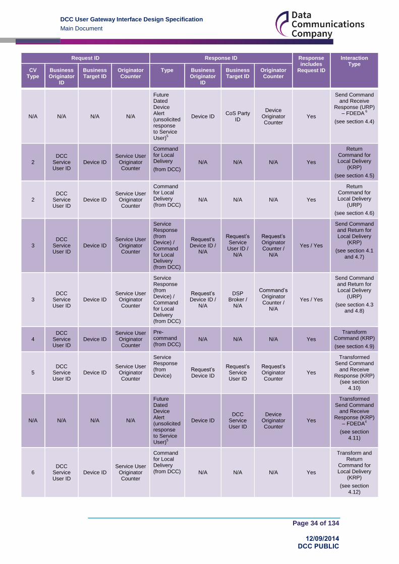
The following table lists Request and Response IDs content in DUGIS format (XML) for the different interaction types. Note that in some cases there are multiple interaction types for a single Command Variant, since the behaviour is different depending on whether the Service Request is being sent by a DCC Service User which is a Known Remote Party (KRP) or Unknown Remote Party (URP) to the Device. Where the DCC Service User is an Unknown Remote Party then the DSP Broker carries out the request on behalf of the DCC Service User
Request ID Response ID Response includes
Request ID
Interaction Type
CV Type
Business Originator
ID
Business Target ID
Originator Counter
Type Business Originator
ID
Business Target ID
Originator Counter
1 DCC
Service User ID
Device ID Service User
Originator Counter
Service Response (from Device)
Request’s Device ID
Request’s Service User ID
Request’s Originator Counter
Yes
Send Command and Receive
Response (KRP) – Command Response
(see section 4.1)
N/A N/A N/A N/A
Future Dated Device Alert (unsolicited response to Service User)
5
Device ID DCC
Service User ID
Device Originator Counter
Yes
Send Command and Receive
Response (KRP) – FDEDA
4
(see section 4.2)
1 DCC
Service User ID
Device ID Service User
Originator Counter
Service Response (from Device)
Request’s Device ID
DSP Broker ID
Command’s Originator Counter
Yes
Send Command and Receive
Response (URP)
(see section 4.3)
DCC User Gateway Interface Design Specification
Main Document
Page 34 of 134
12/09/2014 DCC PUBLIC
Request ID Response ID Response includes
Request ID
Interaction Type
CV Type
Business Originator
ID
Business Target ID
Originator Counter
Type Business Originator
ID
Business Target ID
Originator Counter
N/A N/A N/A N/A
Future Dated Device Alert (unsolicited response to Service User)
5
Device ID CoS Party
ID
Device Originator Counter
Yes
Send Command and Receive
Response (URP) – FDEDA
6
(see section 4.4)
2 DCC
Service User ID
Device ID Service User
Originator Counter
Command for Local Delivery
(from DCC)
N/A N/A N/A Yes
Return Command for Local Delivery
(KRP)
(see section 4.5)
2 DCC
Service User ID
Device ID Service User
Originator Counter
Command for Local Delivery (from DCC)
N/A N/A N/A Yes
Return Command for Local Delivery
(URP)
(see section 4.6)
3 DCC
Service User ID
Device ID Service User
Originator Counter
Service Response (from Device) / Command for Local Delivery (from DCC)
Request’s Device ID /
N/A
Request’s Service
User ID / N/A
Request’s Originator Counter /
N/A
Yes / Yes
Send Command and Return for Local Delivery
(KRP)
(see section 4.1 and 4.7)
3 DCC
Service User ID
Device ID Service User
Originator Counter
Service Response (from Device) / Command for Local Delivery (from DCC)
Request’s Device ID /
N/A
DSP Broker /
N/A
Command’s Originator Counter /
N/A
Yes / Yes
Send Command and Return for Local Delivery
(URP)
(see section 4.3 and 4.8)
4 DCC
Service User ID
Device ID Service User
Originator Counter
Pre-command (from DCC)
N/A N/A N/A Yes
Transform Command (KRP)
(see section 4.9)
5 DCC
Service User ID
Device ID Service User
Originator Counter
Service Response (from Device)
Request’s Device ID
Request’s Service User ID
Request’s Originator Counter
Yes
Transformed Send Command
and Receive Response (KRP)
(see section 4.10)
N/A N/A N/A N/A
Future Dated Device Alert (unsolicited response to Service User)
5
Device ID DCC
Service User ID
Device Originator Counter
Yes
Transformed Send Command
and Receive Response (KRP)
– FDEDA4
(see section 4.11)
6 DCC
Service User ID
Device ID Service User
Originator Counter
Command for Local Delivery (from DCC) N/A N/A N/A Yes
Transform and Return
Command for Local Delivery
(KRP)
(see section 4.12)

DCC User Gateway Interface Design Specification
Main Document
Page 35 of 134
12/09/2014 DCC PUBLIC
Request ID Response ID Response includes
Request ID
Interaction Type
CV Type
Business Originator
ID
Business Target ID
Originator Counter
Type Business Originator
ID
Business Target ID
Originator Counter
7 DCC
Service User ID
Device ID Service User
Originator Counter
Service Response (from Device) / Command for Local Delivery (from DCC)
Request’s Device ID /
N/A
Request’s Service
User ID / N/A
Request’s Originator Counter /
N/A
Yes / Yes
Transformed Send and Return
Command for Local Delivery
(KRP)
(see section 4.10 and 4.13)
8 DCC
Service User ID
DSP Broker ID
Service User Originator Counter
Service Response (from DCC)
N/A N/A N/A Yes
DCC Only
(see section 4.14)
N/A N/A N/A N/A
Device Alert (unsolicited response to Service User)
Device ID DCC
Service User ID
Device Originator Counter
No
Device Alert
(see section 4.15)
N/A N/A N/A N/A
DCC Alert (unsolicited response to Service User)
DSP Broker ID
DCC Service User ID
DSP Broker Originator Counter
No
DCC Alert
(see section 4.16)
N/A1
DSP Broker ID
2
Device ID2
DSP Broker Originator Counter
2
Service Response (from Device)
3
Request’s Device ID
DSP Broker ID
Request’s DSP Broker Originator Counter
Yes2
DSP Scheduled Command and
Response
(see section 4.17)
Table 4 Request and Response IDs
1 Command Variant is N/A to DSP Scheduled Command to a Device
2 The Request ID is generated by the DSP Broker and included in the GBCS Command to the
Device
3 The Response XML and GBCS Payload include the DSP Schedule ID
4 The Device holds the Remote Party ID, Message Code and Future Dated Counter ( =
Originator Counter) of the Command to be executed
5 The Device Alert Payload includes the Command Message Code and Originator Counter of
the executed Command
6 This interaction is only applicable to Service Request 6.23 (Update Security Credentials
(CoS)). The Device holds the Remote Party ID (CoS Party), Message Code and Future Dated Counter ( = Originator Counter) of the Command to be executed. The DCC Data Systems hold the relationship between the Service Request ID (from the DCC Service User) and the Command (from the CoS Party)
The following diagrams illustrate the content of Request and Response IDs in all the interaction types. The values in the diagrams indicate the originator and target rather than their IDs. See section 3 for Command Variants applicable to each case.

DCC User Gateway Interface Design Specification
Main Document
Page 36 of 134
12/09/2014 DCC PUBLIC
Figure 20 Request and Response IDs Diagrams Key
4.1 Send Command and Receive Response (KRP) – Command Response
Applicable to Non-Critical Service Requests Commands from a KRP delivered via SM WAN, where the response is either to an On Demand Command or the Device acceptance of a Future Dated (Device) Command. See section 4.2 for the Device Alert returned when the Future Dated (Device) Command is executed by the Device.
Figure 21 Send Command and Receive Response (KRP) – Command Response
Note that the synchronous Acknowledgement response (flow 2 on the diagram) returns only the original DUGIS Request ID.

DCC User Gateway Interface Design Specification
Main Document
Page 37 of 134
12/09/2014 DCC PUBLIC
4.2 Send Command and Receive Response (KRP) – FDEDA
Applicable to Non-Critical Service Requests Commands from a KRP delivered via SM WAN, where the response is the Future Dated (Device) Execution Device Alert (FDEDA).
There are currently no instances of this interaction.
Figure 22 Send Command and Receive Response (KRP) – FDEDA

DCC User Gateway Interface Design Specification
Main Document
Page 38 of 134
12/09/2014 DCC PUBLIC
4.3 Send Command and Receive Response (URP)
Applicable to Non-Critical Service Requests Commands from an URP delivered via SM WAN. Also applicable to Service Requests 6.21 (Request Handover Of DCC Controlled Device) and 8.5 (Service Opt Out), because even though the DCC Service User submitting the Service Request to the DCC Data Systems is a KRP, the Command is Critical and has to be digitally signed by the DSP Broker.
Figure 23 Send Command and Receive Response (URP)

DCC User Gateway Interface Design Specification
Main Document
Page 39 of 134
12/09/2014 DCC PUBLIC
4.4 Send Command and Receive Response (URP) – FDEDA
Applicable to Non-Critical Service Requests Commands from an URP delivered via SM WAN, where the response is the Future Dated (Device) Execution Device Alert (FDEDA).
The only instance of this interaction is Service Request 6.23 (Update Security Credentials (CoS)).
Figure 24 Send Command and Receive Response (URP) – FDEDA

DCC User Gateway Interface Design Specification
Main Document
Page 40 of 134
12/09/2014 DCC PUBLIC
4.5 Return Command for Local Delivery (KRP)
Applicable to Non-Critical Service Request Commands from a KRP returned to the DCC Service User for Local Delivery.
Figure 25 Return Command for Local Delivery (KRP)
4.6 Return Command for Local Delivery (URP)
Applicable to Non-Critical Service Request Commands from an URP returned to the DCC Service User for Local Delivery.
Figure 26 Return Command for Local Delivery (URP)

DCC User Gateway Interface Design Specification
Main Document
Page 41 of 134
12/09/2014 DCC PUBLIC
4.7 Send Command and Return for Local Delivery (KRP)
Applicable to Non-Critical Service Request Commands from a KRP delivered via SM WAN and returned to the DCC Service User for Local Delivery.
Figure 27 Send Command and Return for Local Delivery (KRP)
4.8 Send Command and Return for Local Delivery (URP)
Applicable to Non-Critical Service Request Commands from an URP delivered via SM WAN and returned to the DCC Service User for Local Delivery.
Figure 28 Send Command and Return for Local Delivery (URP)

DCC User Gateway Interface Design Specification
Main Document
Page 42 of 134
12/09/2014 DCC PUBLIC
4.9 Transform Command (KRP)
Applicable to Critical Service Request Commands.
Figure 29 Transform Command (KRP)
4.10 Transformed Send Command and Receive Response (KRP)
Applicable to Signed Pre-Commands delivered via SM WAN, where the response is either to an On Demand Command or the Device acceptance of a Future Dated (Device) Command. See section 4.11 for the Device Alert returned when the Future Dated (Device) Command is executed by the Device.
Figure 30 Transformed Send Command and Receive Response (KRP)
Note that the synchronous Acknowledgement response (flow 2 on the diagram) returns only the original DUGIS Request ID.

DCC User Gateway Interface Design Specification
Main Document
Page 43 of 134
12/09/2014 DCC PUBLIC
4.11 Transformed Send Command and Receive Response (KRP) – FDEDA
Applicable to Signed Pre-Commands from a KRP delivered via SM WAN, where the response is the Future Dated (Device) Execution Device Alert (FDEDA).
Figure 31 Transformed Send Command and Receive Response (KRP) – FDEDA

DCC User Gateway Interface Design Specification
Main Document
Page 44 of 134
12/09/2014 DCC PUBLIC
4.12 Transform and Return Command for Local Delivery (KRP)
Applicable to Critical Service Request Commands returned to the DCC Service User for Local Delivery.
Figure 32 Transform and Return Command for Local Delivery (KRP)
4.13 Transformed Send and Return Command for Local Delivery (KRP)
Applicable to Signed Pre-Commands delivered via SM WAN and returned to the DCC Service User for Local Delivery.
Figure 33 Transformed Send and Return Command for Local Delivery (KRP)

DCC User Gateway Interface Design Specification
Main Document
Page 45 of 134
12/09/2014 DCC PUBLIC
4.14 DCC Only
Applicable to “DCC Only” Service Requests.
Figure 34 DCC Only
4.15 Device Alert (including Billing Data Alert)
Unsolicited response (Device Alert). The Device sends “Meter Scheduled” Billing Data Log data as an Alert.
Figure 35 Device Alert (including Billing Data Alert)

DCC User Gateway Interface Design Specification
Main Document
Page 46 of 134
12/09/2014 DCC PUBLIC
4.16 DCC Alert
Unsolicited response (DCC Alert).
Figure 36 DCC Alert
4.17 DSP Scheduled Command and Response
Unsolicited response to DCC Service User (request generated by DSP Broker). The Response XML and GBCS Payload include the DSP Schedule ID.
Figure 37 DSP Scheduled Command and Response

DCC User Gateway Interface Design Specification
Main Document
Page 47 of 134
12/09/2014 DCC PUBLIC
4.18 Originator Counters and Anti-Replay
The Originator Counter within the Request ID plays a crucial part in providing protection against replay of Commands at the Device. This is explained in detail in GBCS, however this section attempts to summarise the behaviour for DCC Service Users.
Each Device maintains two counters per Known Remote Party (KRP) and Command type combination for all commands that are marked as requiring ‘Protection Against Replay’ as defined in GBCS ;
Immediate Execution Counters and
Future Dated Counters
The device shall,
1. reject a Command sent for immediate execution, where the Originator Counter in the request is not greater than the value of the Immediate Execution Counter held for that Command type and Remote Party
2. reject a Command sent for future dated execution, where the Originator Counter in the request is not greater than the value of the Future Dated Counter held for that Command type and Remote Party at the point at which the Command is received.
Therefore, if the Command being sent to the Device has ”Protection Against Replay Required” as defined by GBCS then the Device will store the Originator Counter of that Command when processed and only process higher value counters for that Command type and Remote Party combination. This means that the order of processing of Commands on Devices is important for these Commands to ensure that they are successfully processed by the Device. If a DCC Service User sends multiple Service Requests of the same type that require “Protection Against Replay” to the same Device then the DCC Service User must ensure that they are sent and confirmed as completed in order.
If “Protection Against Replay” is not required then DCC Service Users are free to send Service Requests to the device in any order and the originator counter values are not checked by the device.
Table 27 in section 9.4 indicates which Service Requests use Commands that require “Protection Against Replay”.

DCC User Gateway Interface Design Specification
Main Document
Page 48 of 134
12/09/2014 DCC PUBLIC
5 Scheduling There are four main use cases which involve some sort of scheduling, either at the meter or within the DCC Data Systems, as shown in Figure 38.
Figure 38: Scheduled Use Cases
5.1 Future Dated
Future Dated Service Requests incorporate an element of scheduling in that they are retained by either the device or the DCC Data Systems for execution at a specified time and date in the future.
Service Requests which support the ability to be Future Dated have an optional attribute for execution date/time defined within the Service Request Definition (see Annex). If this attribute is set then the Service Request is treated as Future Dated.
For Critical Service Requests which are to be Future Dated at the Device, the initial Transform Service Request requires this attribute to be set in order for the Pre-Command to be created with the required execution date/time. In all cases, the Signed Pre-Command must also include the execution date/time to allow the DSP to schedule and/or track the completion of the Future Dated request.
5.1.1 Future Dated (Device)
The set of commands which can be future dated at the Device is defined by the GBCS. For these commands the DCC actions the Service Request or Signed Pre-Command immediately and sends the command to the device where it is stored for execution at a later date. The device sends a Service Response to indicate acceptance of the future dated command and upon execution sends an Alert to confirm execution. For a list of Service Requests that can be Future Dated at the Device see Table 27, where “Future Dated” column is set to “Device”.
If a Service Request that can be Future Dated at the Device is run On Demand, the Device will simply return a Service Response to confirm execution, in line with the standard On Demand processing pattern.
To cancel a Future Dated Service Request held at the Device, the DCC Service User has to send another Service Request of the same type with a date of 31/12/3000. The Device will cancel the original Command and return a Response to the Cancellation Service Request’s Command but no further Response or Alert will be sent for the original Command being cancelled.

DCC User Gateway Interface Design Specification
Main Document
Page 49 of 134
12/09/2014 DCC PUBLIC
If there is a change of Supplier on a Device which is after a future dated Command is stored but before it is activated, the change of control process will cancel that Command at the point of updating the Security Credentials. No Response or Alert will be returned by the Device to either the old or new Supplier in relation to any such cancellations. See GBCS for details.
5.1.2 Future Dated (DSP)
If a command cannot be Future Dated at the Device then the DCC can provide a similar function within the DCC Data Systems. In this case the Command is stored within the DCC Data Systems for a future scheduled delivery. This scheduling will be activated at the requested execution date and time and will be delivered in line with the relevant Target Response Time for Future Dated commands. Upon delivery the Device then sends a Service Response to confirm execution as it would for any other immediate execution of a command.. For a list of Service Requests that can be Future Dated at the DSP see Table 27, where “Future Dated” column is set to “DSP”.
To cancel a Future Dated Service Request held at the DSP, the DCC Service User has to send another Service Request of the same type with a date of 31/12/3000. The DCC Data Systems will cancel the original Service Request and return a Service Response to the cancellation Service Request, but no further Service Response will be sent for the original Service Request being cancelled.
5.2 Meter Scheduled
Electricity and Gas Smart Meters are capable of maintaining a meter held schedule for delivery of data from the Billing Data Log as defined in SMETS. The schedule is set by the Registered Energy Supplier using the Update Billing Configuration Calendar Service Request 6.8, with this request being passed directly to the meter the same as any other configuration command. Once the billing calendar has been set, the meter will initiate the sending of billing data as a specific Billing Data Log Device Alert at the stated date/time as per the schedule.
The DCC Data Systems receives these scheduled Device Alerts as unsolicited messages and processes them accordingly, forwarding them to the relevant DCC Service User.
5.3 DSP Scheduled
DCC Service Users may create schedules for sending Service Requests which are maintained and executed by the DCC Data Systems. Such schedules are created using the Create Schedule Service Request 5.1 and are stored within DCC Data Systems. At the relevant date and time, the DCC Data Systems sends the required Service Request to the Device and receives the Service Response. This Service Response is then returned to the DCC Service User that set up the schedule.
On successful creation of a Schedule, the Service Response to Service Request 5.1 includes a unique Schedule Id which is returned to the DCC Service User. When subsequent Service Requests are sent according to this schedule then the corresponding Service Responses will identify the Schedule Id from which they were created.
5.4 Pre-installation Service Requests
Although not explicitly a scheduling function, the DCC will carry out a form of scheduling for Service Requests which are sent prior to a Device being installed. In this case, as long as the Device has been pre-notified then the DCC will hold the Service Request and release it to the Device once the specified Device has been commissioned.

DCC User Gateway Interface Design Specification
Main Document
Page 50 of 134
12/09/2014 DCC PUBLIC
6 Sequencing A DCC Service User has the option to orchestrate a number of Service Requests and Signed Pre-Commands into a business process through the use of sequencing. Each Service Request or Signed Pre-Command in the sequence is only released for execution once the previous one in the sequence has completed successfully.
In this section the term Request is used to refer to Service Requests or Signed Pre-Commands, where the behaviour is applicable to both.
Sequencing is only applicable to Requests that are for execution on Devices and more specifically (see section 3 and section 2.3):
non-Critical Service Requests
and Critical Signed Pre-commands
o Critical Requests are submitted to the DCC Data Systems twice, both times
with the same Request ID. First as a Service Request to be transformed to
a Pre-command and second as a Signed Pre-command to be executed by
the Device. When sent as part of a sequence, both Requests will include
the sequencing related common data items, i.e. First In Sequence flag and
/ or Preceding Request ID (see section 9.2). The DCC Data Systems will
ignore these data items in the Service Request for transformation but will
use them in the Signed Pre-command. This is in line with the general
sequencing orchestration rule to only release a Request for execution once
the previous one has completed
CV = 1 CV = 2 CV = 3 CV = 4 CV = 5 CV = 6 CV = 7 CV = 8
Yes No Yes No Yes No Yes
No
Table 5 Command Variant Values valid for sequencing
Sequencing is not applicable to:
Transformation of Service Requests
o See Critical Signed Pre-commands bullet point above
DCC Only Service Requests. These Service Requests should be atomic in their
own right and the purpose of sequencing is only to guarantee the order of
Command execution on a Device
Commands to be delivered locally. For these Requests the DCC Data Systems
could ensure the order in which the Commands are returned to the DCC Service
User, but not the order in which the Commands are delivered to the Device which
makes the service redundant
DSP Scheduled Service Requests
All Gas Service Requests that return encrypted data. In this case the DSP cannot
read the message which includes the Response Code from the Device indicating
successful execution or error reason and so cannot determine when to release
subsequent Service Requests to the Device. See Table 27 for details
The DCC Data Systems will process sequenced Requests in the order specified by the DCC Service User.
The following diagram illustrates the successful processing of a sequence of 3 “On Demand” Non-Critical Requests (Request ID = 1 is the “First In Sequence”. Request ID = 2 “Preceding Service Request ID” = 1 and Request ID = 3 “Preceding Service Request ID” = 2):

DCC User Gateway Interface Design Specification
Main Document
Page 51 of 134
12/09/2014 DCC PUBLIC
Figure 39 Sequencing – “On Demand” Non-Critical Requests
6.1 Starting a Sequence
The first Request in a sequence will have the First In Sequence flag set to true and no Preceding Request ID.
The DCC Data Systems treat the first Request in a sequence as a non-sequenced Request, except
the First In Sequence flag being set to true is used to identify that its Command
completion has to be monitored
6.2 Continuing a Sequence
The DCC Data Systems shall process all Requests in a sequence in the order specified by the DCC Service User. All Requests in a sequence, except the first one, will have the First In Sequence flag set to false and the Preceding Request ID set to the Request ID of an earlier Request in the sequence.
Each Request that is intended to be sequenced from another Request shall only trigger the release of a single Request. The DCC Service User shall not link multiple Requests to a single Preceding Request ID.
If a Request is part of a sequence, its associated Command is only released by the DCC Data Systems to the specified Device for execution once its preceding Request’s associated Command has completed successfully on the Device and a response is received by the DCC Data Systems.
6.3 Ending a Sequence
The DCC Data Systems will identify the last Request in the sequence in one of two ways:
as the Request that makes the number of Requests in the Sequence reach the
maximum number of Requests supported in a Sequence (currently set to a
maximum of 99)
as the last Request with a Preceding Request ID and with its Request ID not being
the Preceding Request ID of another Request

DCC User Gateway Interface Design Specification
Main Document
Page 52 of 134
12/09/2014 DCC PUBLIC
o The DCC Data Systems will wait for up to 2 minutes from the reception of a
sequenced Request to determine if it is the last in the Sequence
If after the Last Request in the Sequence has been determined a subsequent Request is received, itself and any subsequent Requests will be set to errored.
Their Acknowledgement Message Response Code will be set to E46 (provided they
don’t fail XSD validation or Access Control)
Note that the Sequence itself won’t be failed and all Requests up to the last in the sequence that are still held, will be processed as defined in section 6.2.
6.4 Failed Sequenced Requests
Should a Request in a chain of sequenced Requests fail validation or execution, then the Sequence and all its held Requests (including any already received out of order) will be marked as failed and a DCC Alert will be sent to the DCC Service User. See Table 39 (DCC Alert Code N14) and Annex section 16.
For subsequent Requests received after the Sequence had failed, the Acknowledgement Message Response Code will be set to E43 and no DCC Alert will be returned to the DCC Service User.
There is no attempt to reverse the action of the preceding successful Requests and it is the responsibility of the DCC Service User to resend corrected failed Requests (either as non-sequenced or as part of a new sequence), having first examined the failure reason given in the response message and corrected the underlying fault.
6.5 Quarantining of Sequenced Requests
In the event that a Request received as part of a sequence is identified as anomalous and is Quarantined, all not yet processed Requests identified as being part of that sequence shall also be held alongside the anomalous Request and processed or rejected as a set in accordance with the DCC Service User’s instruction.
6.6 Out of Order Sequenced Requests
If sequenced Requests are received out of order, the DCC Data Systems shall cache the request for a “Wait Period” of 2 minutes from the reception of the Request to allow the missing Request to be received. If the missing Request is received within that period then the processing shall proceed as normal. If not, then the cached Request is not executed, the Sequence is marked as failed and a DCC Alert is sent to the DCC Service User. See Table 39 (DCC Alert Code N15) and Annex section 16.
Any held subsequent Requests in the sequence dependent on the one just failed, will also be marked as failed and a DCC Alert (DCC Alert Code N15) sent to the DCC Service User.
For subsequent Requests received after the Sequence had failed (and provided they don’t fail XSD validation or Access Control), the Acknowledgement Message Response Code will be set to E44 and no DCC Alert will be returned to the DCC Service User.
If the missing Request is received once the “Wait Period” has elapsed, it will be treated as the subsequent Requests received once the Sequence has failed.
6.7 No Sequence Number
The use of Sequencing is optional. Where the data items that indicate a Request is part of a Sequence (First In Sequence or Preceding Request ID) aren’t included in Requests, the ordering of execution of Requests for a given device is not guaranteed.

DCC User Gateway Interface Design Specification
Main Document
Page 53 of 134
12/09/2014 DCC PUBLIC
7 Access Control All Service Requests and Signed Pre-Commands submitted by the DCC Service User via the DCC User Gateway Interface undergo three logical modes of Access Control, namely: Authentication, Validation and Authorisation.
(In this section the term Request is used to refer to Service Requests or Signed Pre-Commands, where the behaviour is applicable to both.)
Authentication is based on two form factors: one covering the establishment of a secure communications channel, the other authentication of individual Requests. Similarly, Validation consists of both XSD Schema validation and data content validation. There are thus 3 modes but 5 stages of Access Control, See Table 6.
Mode Stage Description
Authentication Communications Authentication
Has the DCC Service User established a secure communications channel with the DCC, using a valid corporate TLS certificate issued by the DCC key Infrastructure (DCCKI)?
Validation XSD Validation Is the Request consistent with the DUGIS XML Schema?
Authentication Request Authentication
Has the Request been signed with a valid certificate issued by the Smart Meters Key Infrastructure (SMKI)?
Authorisation Request Authorisation
Is the DCC Service User organisation and associated User Role a valid SEC party of active status?
If so, does the User Role specified have access rights to perform the Request for the specified Device?
Validation Data Validation Is the Request valid and complete?
Table 6 Access Control Stages
The checks carried out as part of the various Access Control stages meet the obligations as outlined in SEC Section H4.11, including the obligation to Verify the Service Request meets the requirements of the DCC User Gateway Interface Specification.
The DCC Data Systems will only process Requests for which the 3 Access Control modes are successful.
As soon as any one Access Control check fails, the processing of the Request is halted and an error response is returned to the DCC Service User with an appropriate response code or HTTP status code indicating the error reason.
Authorisation and Data Validation is also applied for a second time at the point a “DSP Scheduled” Command or a “CoS Update Security Credentials” Command are generated by the DCC.
7.1 Stage 1 – Communications Authentication
All communications between the DCC and DCC Service Users shall be via a secure communications channel. Individual XML Requests will flow over this secure communications channel.
The communications channel will consist of an encrypted and authenticated session between a DCC and DCC Service User Policy Enforcement Point (PEP). This session will be based on the Transport Layer Security (TLS) v1.1 protocol standard and will make use of mutual authentication using PKCS #3 Ephemeral Diffie Hellman key exchange to generate a shared secret (TLS-DHE-RSA) with AES256-CBC-SHA256 for communications encryption. The RSA Signing Key is the PEP corporate Digital Signing Key. This may support more than one organisation as defined by the Smart Meter Key Infrastructure (SMKI) organisation id. If this Authentication step fails then a TLS message of Access Denied will be returned to the DCC Service User. See section 15 for details.
The RSA (public) Signing Key will be issued to the DCC Key Infrastructure along with a PKCS #3 Certificate Signing Request. The Certificates for both PEPs keys will be stored on

DCC User Gateway Interface Design Specification
Main Document
Page 54 of 134
12/09/2014 DCC PUBLIC
the DCC Public Key Store. The process for Certificate request / verification is described in section 15.
The establishment of this communications channel is illustrated in Figure 40 Secure Communications Channel.
Figure 40 Secure Communications Channel
Facilities on the left hand side of the Logical Boundary of the DCCUG are owned and supplied by the DCC Service User. These reflect the expectation that each DCC Service User will put in place a boundary protection device that is capable of enforcing the TLS controls specified. The PEP must have logical access to a key store for TLS authentication and be able to create or import keys in a secure fashion such as via a Cryptographic Module. What provides the PEP capability, whether there is an Cryptographic Module in operation and the nature of the Local Public Key Store is at the discretion of the DCC Service User and their own risk assessment and risk treatment, subject to SEC conditions.
7.2 Stage 2 – XSD Validation
All Requests sent to the DCC User Gateway Interface will be subject to XSD Schema Validation.
If validation fails, the DCC Data Systems won’t return a Synchronous Response as defined in section 9.3.1. Instead an HTTP status code 400 will be returned to the DCC Service User.
It is the DCC Service Users responsibility to ensure their Requests have been XSD Schema validated.
Validation Check Process
Is the Service Reference valid?
Check that the Service Reference contained within an incoming Request from a DCC Service User is a valid and recognised request that can be received and processed by the DCC Data Systems.
Is the Service Reference format valid?
Check that the format of the Request is valid as per the Service Reference but not the content of the individual data items
Is the Request syntactically correct?
Check that the Request structure is syntactically correct with respect to the XML schema.
Are the Request’s data items valid?
Check that all the data items in the Request are valid according to
the XSD. See DUGIS XML Schema
Table 7 XSD Validation Checks

DCC User Gateway Interface Design Specification
Main Document
Page 55 of 134
12/09/2014 DCC PUBLIC
7.3 Stage 3 – Request Authentication
Where XSD validation is passed then the Request will be authenticated through the consumption of a Digital Signature applied to each and every XML format Request. This Digital Signature will be the organisational P-256 bit Elliptic Curve Digital Signature Algorithm (ECDSA) key generated under the auspices of the Smart Meter Key Infrastructure (SMKI).
This is illustrated in the diagram below.
Figure 41 XML Request Authentication
To support graceful transition when approaching certificate expiry (or graceful non-emergency certificate revocation) the XML Digital Signature element KeyInfo must be
included in the digital signature and it must define the certificate used to sign the request using a single X509IssuerSerial element (in a single X509Data element). This enables
support for overlapping certificates for a period of time during a certificate transition.
In the case of all XML format Requests received by the DCC Data Systems via the DCC User Gateway Interface, the DCC will conduct the following checks.

DCC User Gateway Interface Design Specification
Main Document
Page 56 of 134
12/09/2014 DCC PUBLIC
Message
Authentication Check
Process Response Code
(if checks are failed)
Has the DCC Service User presented a valid SMKI client certificate?
The SMKI digital certificate referred to in the Request XML is verified to prove that the DCC Service User is eligible to communicate with the DCC Data Systems and the Request is intended for the DCC Data Systems.
Check Steps:
1. Check that the DCC Service User organisation ID in the
Request Business Originator ID is consistent with the
corporate ID used to secure the TLS connection (see
section 15)
2. Use the KeyInfo in the Request to access the DCC
Service User’s signing certificate and check that it
matches the signing certificate of the Request Business
Originator ID
3. Use the public key from the DCC Service User’s
certificate to verify the authenticity of the Request
4. Verify the certificate’s chain of trust up to the DCC root
CA
5. Check the Certificate Revocation List to verify that no
certificates in the chain of trust have expired or been
revoked
E100
Table 8 Authentication Check Steps
Requests that fail authentication will not be processed by the DCC Data Systems. The DCC Service User will be advised should authentication fail as part of the Service Response or Acknowledgment generated and sent to the requesting DCC Service User with an appropriate Response Code as listed in Table 8 above.
7.4 Stage 4 – Request Authorisation
The permissions associated with the presented SMKI Certificate are checked to ensure that it has permission to perform the method requested.
This check is comprised of the following steps:
Authorisation Check Process Response Code
Does the DCC Service User have a valid User Role?
The sending organisation (DCC Service User) and their associated User Role are checked to confirm it is a valid SEC party / User Role combination
E1
Does the DCC User Role allow them to call that Request?
This is a User Role based check for the mapping between Requests and DCC Service User Roles (see section 9.4) E2
Does the DCC Service User’s status allow them to call that Request?
This is a status based check to find out if the DCC Service User is suspended (not allowed to run that Request) during the period against which the Request is placed for
E3
Is the DCC Service User, in the User Role defined in the Request, a “legitimate Registered Party” for the Device?
1
This check is based on the registration data for the Device, and the date of execution of the Request or, for historical data, on the date-time period for which the data is required E4
Is the Service Reference applicable to the Device status?
2
This is a check to confirm that the target Device has a status within the Smart Metering Inventory that enables the DCC Service User to send it the particular Request
3
E5

DCC User Gateway Interface Design Specification
Main Document
Page 57 of 134
12/09/2014 DCC PUBLIC
Authorisation Check Process Response Code
Does the User Role / Device status allow the Request to be delivered locally?
This is a check to confirm that if a Request is to be delivered locally (see section 3) the DCC User Role / Device status combination allows it (see section 9.4.1)
E17
Does the Device exist?2
This is a check to confirm that a Device exists E19
Table 9 Authorisation Check Steps
1 The registration data check only applies to Energy Suppliers, Network Operators or Supplier Nominated
Agents and is not applied for Critical Service Requests and Signed Pre-Commands.
A “legitimate Registered Party” means that a given DCC Service User is associated with an
energy market participant having an industry registration data record for a given MPxN and in a
given User Role on a given date, where there is not a Change of Supplier Objection against the
industry registration data Supplier relationship effective on that date, with a status of Objection
Raised or Objection Upheld
o Where there is an Objection with one of the statuses given above against the
Supplier relationship effective on that date, then the “legitimate Registered Party” is
the DCC Service User associated with the previous industry registration data record
for the same MPxN and in the same User Role without such an Objection.
If the Device Type is a Communications Hub, this check is done on the Device(s) being added
to or already existing on the same HAN for which the Service User / User Role is a Registered
Party.
If the Device Type is a ‘Type 1’, ‘Type 2’ or Gas Proxy Function, this check is done on the HAN
Device(s) joined to it for which the Service User / User Role is a Registered Party.
Authorisation is done using the device specified in the business target id except for “DCC Only” Service Requests, where the Target Device ID is specified in the Request itself, where applicable.
Authorisation for Service Request 8.2 is done by checking that the Service User is authorised
for at least one Device in the Premises identified by the Request. In the case of the Import
Supplier this could be the current or the future (‘pending’) registered Supplier.
2 This check is not applicable to Service Requests that are not addressed to a specified Device, e.g. 12.1
(Request WAN Matrix)
3 Devices in a Suspended state can be communicated with only by the Registered Supplier.
If any of these checks fails at the point the Request is received by the DCC Data Systems, the Request is errored, no further checks are carried out and a Service Response is generated with the appropriate Response Code (error message) to inform the DCC Service User of the issue identified. See section 12.3 for Response Code details.
If any of these checks fails at the point a “DSP Scheduled” Command or a “CoS Update Security Credentials” Command is being generated, the associated Service Request is also errored, no further checks are carried out and a Service Response (see Table 39) is generated with the appropriate Response Code (error message) to inform the DCC Service User of the issue identified.
7.5 Stage 5 – Data Validation
All Requests sent to the DCC User Gateway Interface will be subject to Data Validation. Data Validation is driven by application functionality rather than syntax.
Service Request specific validation is included in the Annex Service Request Definitions. The table below describes common validation checks.
Data validation checks (see section 12.3 for more information on Response Code details):

DCC User Gateway Interface Design Specification
Main Document
Page 58 of 134
12/09/2014 DCC PUBLIC
Validation Check Process Response Code
Is the Request applicable to the Device type and, for Electricity Smart Meter, its variant?
2
Check that the Request content is applicable to the
Device type (and, for Electricity Smart Meter, its variant),
e.g. Service Request 14.1 Record Network Data (Gas) is
only applicable to a Gas Smart Meter1
E11
Is the Request’s Command Variant valid?
2
Check that the Command Variant (see section 3) is
applicable to the Request E12
Is the Request valid for the Web Service?
Check that the Request has been sent to the correct Web
Service. See section 2.4 E13
Is the first request in a sequence valid?
Check that if the Request includes the FirstInSequence
flag set to true, it doesn’t include a PrecedingRequestID E40
Is the sequenced Request’s PrecedingRequestID the PrecedingRequestID of another Request?
Check that the sequenced Request’s
PrecedingRequestID is not the PrecedingRequestID of
another Request E41
Does the sequence contain a circular reference?
Check that there are no circular references in the
sequence, i.e. a Request’s PrecedingRequestID is not its
own RequestID or the PrecedingRequestID of a
Preceding Request in the sequence is not the currently
processed Request’s RequestID
E42
Have any of the sequenced Request’s Preceding Requests failed?
Check that none of the Request’s Preceding Requests
have failed E43
Have all the sequenced Request’s Preceding Requests been received?
1
Check that all Request’s Preceding Requests in the
sequence have been received during their “Wait Period”
(see section 6.6)
E44
Is the sequenced Request’s Command Variant valid?
Check that the Command Variant (see section 3) is
applicable to sequenced Requests (see section 5) E45
Has the sequenced Request been received before the Last in Sequence has been determined?
3
Check that the Request does not follow a Request that
has been determined to be the Last In Sequence (see
section 6.3) E46
Have any of the sequenced Request’s Preceding Request Responses been received?
Check that the Request has not been received after the Sequence has been failed because of no response received from the Device to an “On Demand” Command E47
Is the ServiceReference / ServiceReferenceVariant combination valid?
Check that the combination of Service Reference and Service Reference Variant is correct, i.e. it aligns to the definitions in Table 27.
E48
Is the Request Format correct for the Request?
2
Check that the actual Request format matches the Service Reference Variant in the message header E49
Is the Command for Local Delivery being quarantined?
Check that if a Request is to be delivered locally (Command Variant 2 or 6), it is not being quarantined E50
Is the Signed Pre-Command GBCS message code correct?
4
Check that the GBCS message code in the Signed Pre-Command is consistent with the Service Reference Variant contained in the XML Request Header
E51
Table 10 Data Validation Checks

DCC User Gateway Interface Design Specification
Main Document
Page 59 of 134
12/09/2014 DCC PUBLIC
1 This check is not applicable to Service Requests that don’t include a specified Device, e.g. 12.1 (Request
WAN Matrix)
2 Validation is only applied to the XML data within the Request. There is no validation of the format of the
GBCS Command held within a Signed Pre-Command
3 Validation takes into account Out of Order Sequenced Requests Rules (see section 6.6) and it will only
fail if the “Wait Period” for the Preceding Requests has elapsed
4 Validation only applicable to GBCS Command held within a Signed Pre-Command
7.6 Responses and Alerts
When sending Responses and Alerts to DCC Service Users, the DCC Data Systems have to determine the correct recipient of those Responses or Alerts. This is the only relevant “access control” carried out for Responses or Alerts.
The rules below describe how this is determined:
1. Device Response. The DCC Data Systems forward the Device Response to the
Business Target ID specified in the Device Response. Where the Business Target ID is
the Access Control Broker acting on behalf of an URP the DCC Data Systems forward
the Device Response to the DCC Service User that made the original Request. There is
no checking against Registration data to determine Response routing.
2. Device Alert. The DCC Data Systems forward the Device Alert to the Business Target ID
in the Device Alert and, for those with two recipients, also to the Supplementary Remote
Party ID in the Device Alert. There is no checking against Registration data to determine
Alert routing.
3. DCC Alert. The DCC Data Systems generates the Alert in response to a trigger and
sends it to the Recipient(s) associated to that DCC Alert (see Table 39) via checking
against Registration data to determine the registered recipient, where applicable.

DCC User Gateway Interface Design Specification
Main Document
Page 60 of 134
12/09/2014 DCC PUBLIC
8 Security
8.1 Introduction
Much of the content, processing and structure of Remote Party Messages (as defined in GBCS) are common across multiple Messages. This Section lays out such common requirements with a specific focus on interactions between the DCC Service User and DCC User Gateway Services.
The following Section includes use cases between the DCC and DCC Service User that fall outside the scope of the GB Companion specification as they do not involve Device communications. It also includes use cases that are included within the GB Companion Specification but with embellishments supplied in relation to the interaction between and actions of the DCC and the DCC Service User.
Please note; one significant clarification that has been made with respect to those diagrams in the GB Companion Specification is that the Transform Service (DCC) (see section 2.4) is a dedicated function solely to support Critical Command Transformation and Signing. For Non-Critical Commands, transformation is seen as part of the core DCC Send Command Service and is performed within that service.
It should be noted that while there may be overlap between the sequence diagrams in section 8.3 and those within the GB Companion Specification, it is only those items shown within yellow notes boxes in the sequence diagrams that form part of the formal GB Companion Specification. For such items the GB Companion Specification takes precedence. This document represents the definitive specification for all other activities shown within the sequence diagrams included below.
This is fully consistent with the GB Companion Specification itself, which states that “only those parts of the sequence diagrams within yellow notes boxes are within the scope of the GBCS. The steps outside such boxes are provided for context and, where mandated, are mandated through mechanisms outside the GBCS, for example the Smart Energy Code.”
Embellishments to our sequence diagrams include:
clarification of the use of XML Messaging between DCC Service User and the DCC;
clarification that Signatures are required to be applied to the XML messages (see section
8.2 for details of keys that are used);
confirmation that the DCC issues an Acknowledgement message in response to Service
Request and Signed Pre Commands for all Asynchronous communications;
clarification as to the specific DCC service with which a DCC Service User interacts
where applicable, e.g. Send Command Service, Transform Service etc.;
clarification as to the format of each DCC Service User to DCC Communication.
Note that all Service Responses and Alerts go via the Receive Response Service.
Where such use cases include Device communications we have generally included those communications and Device operations to provide context. We have simplified these where possible while retaining the essence of the use case flow.
8.1.1 Device KRP and URP
Where a Remote Party is known to a Device by way of that Remote Party’s Security Credentials being stored on the Device, the Remote Party is referred to as a Known Remote Party (KRP). Otherwise, it is referred to as an Unknown Remote Party (URP). See GBCS for details.
In all cases where a User Role doesn’t map to a Device KRP, but SEC states that the User Role has access to a Service Request, the User Role is an URP and the Command is sent to

DCC User Gateway Interface Design Specification
Main Document
Page 61 of 134
12/09/2014 DCC PUBLIC
the Device by the Access Control Broker, i.e. the DSP Broker, and the Device Response is returned to the Access Control Broker.
The following table summarises (as defined in GBCS) which User Roles are Known Remote Parties to which Devices:
Known Remote Party Device Type
User Role
Remote Party Role
Key Usage Cell Usage ESME GSME CHF GPF HCALCS PPMID
EIS Supplier Digital Signature Management
EIS Supplier Key Agreement Management
EIS Supplier Key Agreement Pre Payment
Top Up
GIS Supplier Digital Signature Management
GIS Supplier Key Agreement Management
GIS Supplier Key Agreement Pre Payment
Top Up
ENO Network Operator
Digital Signature Management
ENO Network Operator
Key Agreement Management
GNO Network Operator
Digital Signature Management
GNO Network Operator
Key Agreement Management
N/A Access Control Broker
Digital Signature Management
N/A Access Control Broker
Key Agreement Management
N/A WAN
Provider Digital Signature Management
N/A Transitional
CoS Digital Signature Management
N/A Root Key Certificate
Signing Management
Table 11 User Roles and Device KRPs
8.2 Key Cryptographic Operations
The following Cryptographic operations are in addition to those specified within the GB Companion Specification.
8.2.1 DUGIS XML Service Request Signing
All Service Requests are initially issued via XML messaging. A Digital Signature shall be applied by the DCC Service User to each and every XML message sent to the DCC. This shall be signed with an organisational P-256 bit Elliptic Curve Digital Signature Algorithm (ECDSA) key generated under the auspices of the Smart Meter Key Infrastructure (SMKI). This signature should be generated in accordance with NSA Suite B.
See section 7.3 for additional details.

DCC User Gateway Interface Design Specification
Main Document
Page 62 of 134
12/09/2014 DCC PUBLIC
8.2.2 Transform Service Response Signature Validation
The DCC will digitally sign all XML response messages (Pre-Commands) containing Transformed Critical Commands returned by the DCC to DCC Service Users.
These Pre-Commands shall be signed by the DCC with a DCC Transform Service P-256 bit Elliptic Curve Digital Signature Algorithm (ECDSA) key generated under the auspices of the Smart Meter Key Infrastructure (SMKI).
The DCC Service User shall verify the Digital Signature of such Pre- Commands returned by the DCC and this includes Certificate status checking and Certificate Path Validation of the Public Key Certificate of the DCC Transform Service.
8.2.3 DCC Signed Service Responses
The DCC will digitally sign the following XML response messages to DCC Service Users
all DCC Alert messages, originating from the DCC;
all Service Responses to DCC Only Service Requests that return data;
all Service Responses returning Command(s) for Local Delivery;
all Service Responses to Non-Critical Non-Sensitive Commands from an Unknown
Remote Party.
These messages will be digitally signed by the DCC with a DCC Access Control Broker Service P-256 bit Elliptic Curve Digital Signature Algorithm (ECDSA) key generated under the auspices of the Smart Meter Key Infrastructure (SMKI).
The DCC Service User shall verify the Digital Signature of such DCC Signed Service Responses. This shall include Certificate status checking and Certificate Path Validation of the Public Key Certificate of the DCC Access Control Broker Service.
To support graceful transition when approaching certificate expiry (or graceful non-emergency certificate revocation) the XML Digital Signature element KeyInfo is included in
the digital signature of signed responses and it defines the certificate used to sign the request using a single X509IssuerSerial element (in a single X509Data element). DCC Service
Users must support overlapping certificates for a period of time during a certificate transition.
8.3 Sequence Diagrams
The sequence diagrams in the figures in this section 8 illustrate the generic processing stages and common processing requirements, where a Device is operated via the DCC.
Note that those parts of the sequence diagrams within yellow notes boxes are within the scope of the GBCS. The steps outside such boxes are mandated via this Design Specification.
For readability, these diagrams use the term “DSP Broker” to refer to the DCC Access Control Broker.

DCC User Gateway Interface Design Specification
Main Document
Page 63 of 134
12/09/2014 DCC PUBLIC
8.3.1 SME.C.C – Critical Command from Known Remote Party (KRP)
This service request follows the pattern of that specified in GB Companion Specification subject to the above clarifications described in section 8.1.
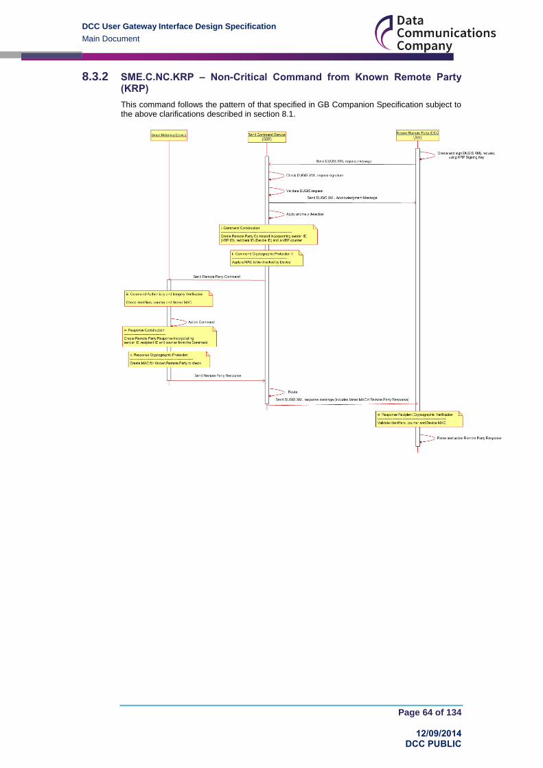
DCC User Gateway Interface Design Specification
Main Document
Page 64 of 134
12/09/2014 DCC PUBLIC
8.3.2 SME.C.NC.KRP – Non-Critical Command from Known Remote Party (KRP)
This command follows the pattern of that specified in GB Companion Specification subject to the above clarifications described in section 8.1.

DCC User Gateway Interface Design Specification
Main Document
Page 65 of 134
12/09/2014 DCC PUBLIC
8.3.3 SME.C.NC.URP – Non-Critical Command from Unknown Remote Party (URP)
This command follows the pattern of that specified in GB Companion Specification subject to the above clarifications described in section 8.1.
It varies from SME.C.NC.KRP in that the Device is not aware of the Unknown Remote Party, its associated keys, etc. and hence has to relay the response through the Send Command Service.
To support this the Send Command Service has to apply its own message counter to the outbound command to enable the Device to generate a response GMAC’d for the Send Command Service which then has to validate this GMAC and sign the XML message to the Unknown Remote Party.

DCC User Gateway Interface Design Specification
Main Document
Page 66 of 134
12/09/2014 DCC PUBLIC
8.3.4 SME.C.NC.URP.SEN – Non-Critical Command from Unknown Remote Party (Sensitive Response)
This Service Request follows the pattern of that specified in GB Companion Specification subject to the above clarifications described in section 8.1.
It builds on and varies from SME.C.NC.KRP in that the Device has to encrypt the sensitive element of the response message, such that the sensitive element cannot be read by anyone other than the Unknown Remote Party (URP).
To support this the Send Command Service has to apply both its own counter and add the public key of the URP to the outbound command to enable the Device to generate a response GMAC’d for the Send Command Service and encrypt the sensitive element for the URP.
The Send Command Service then has to validate this GMAC on the service response and Sign the XML message to the URP. The URP is able to decrypt the sensitive element through generation of the Device shared Secret, generated via Elliptic Curve Diffie Helman (ECDH) based on the URP and Device key agreement keys.

DCC User Gateway Interface Design Specification
Main Document
Page 67 of 134
12/09/2014 DCC PUBLIC
8.3.5 SME.C.NC.KRP.SCH – Non-Critical Command from Known Remote Party (DSP Scheduled)
This Service Request follows the pattern of that specified in GB Companion Specification subject to the above clarifications described in section 8.1.
It builds on and varies from SME.C.NC.KRP, through the addition of a Send Command Service scheduling function. Note that we have not reiterated in this diagram how the Send Command Service receives the schedule in the first place which is no different from how it receives any other Non-Critical Command.
To support this the Send Command Service has to apply both its own message counter to ensure that each specific Device Command is unique. It also has to ensure the KRP message counter is added so that the KRP can associate the response with its original schedule request.

DCC User Gateway Interface Design Specification
Main Document
Page 68 of 134
12/09/2014 DCC PUBLIC
8.3.6 SME.A.C – Critical Alert to Known Remote Party
This command follows the pattern of that specified in GB Companion Specification subject to the above clarifications described in section 8.1.
8.3.7 SME.A.NC – Non-Critical Alert to Known Remote Party
This command follows the pattern of that specified in GB Companion Specification subject to the above clarifications described in section 8.1. Note that all Alerts go via the Receive Response Service.

DCC User Gateway Interface Design Specification
Main Document
Page 69 of 134
12/09/2014 DCC PUBLIC
8.3.8 DCC.A – Alert from DSP to DCC Service User
This Alert represents a DCC to DCC Service User interaction that falls outside of the Scope of the GB Companion Specification described in section 8.1. Note that all Alerts go via the Receive Response Service.

DCC User Gateway Interface Design Specification
Main Document
Page 70 of 134
12/09/2014 DCC PUBLIC
8.3.9 DCC.C – Command from DCC Service User to DCC
This command represents a DCC to DCC Service User interaction that falls outside of the scope of the GB Companion Specification.
It shows how a DCC Service User issues a Service Request via XML to the DCC Only Service; what steps the DCC Only Service takes in terms of its processing, from a security perspective; and the form of the response. Note that communications in both directions are via XML messages signed using the digital signing key of the sending party.

DCC User Gateway Interface Design Specification
Main Document
Page 71 of 134
12/09/2014 DCC PUBLIC
9 Request and Response Definitions This section defines the Request and Response Formats and their Header and Common Data Items. The more detailed data attributes associated with each Service Request, Service Response, Device Alert and DCC Alert are contained within the Annex – Service Request Definitions document (Annex).
This documentation set uses the data types defined in XML (prefixed with xs: and data types defined in this documentation set (prefixed with sr:).
9.1 Request and Response XSD Diagrams
The XSD diagrams in the following 2 sections and in the Annex consist of the following components, described in this example diagram:
Figure 42 XSD Diagram Components
Example is a complex element consisting of:
A sequence of
o Mandatory SequenceElement1
o Optional SequenceElement2
o A mandatory choice of one of
ChoiceElement1
ChoiceElement2
ChoiceElement3
Note that all diagrams include the Schema version attribute for the top level element – see section 9.5 for a description of how versions are used.

DCC User Gateway Interface Design Specification
Main Document
Page 72 of 134
12/09/2014 DCC PUBLIC
9.2 Request Format
The Request format is defined in the Request XML element of the XSD (see DUGIS XML Schema).
Figure 43 Request Structure
The above diagram is to be read as:
A Request is a sequence of
o A mandatory Header. It contains the Request Header Data Items. See
Table 12
o A mandatory Body. It contains the choice of Service Request Variants and
Signed Pre-command. See section 9.2.1
o A mandatory Signature (defined in a separate schema). See XMLDSIG
XSD for details on the signature schema. It contains the DCC Service User
SMKI digital signature of the XML message. See section 8.2.
The following table details the data items in the Header:

DCC User Gateway Interface Design Specification
Main Document
Page 73 of 134
12/09/2014 DCC PUBLIC
Data Item Description / Valid Set Type Mandatory
Default Units Sensitivity
RequestID Concatenation of BusinessOriginatorID, BusinessTargetID and OriginatorCounter as defined in GBCS, separated by “:”. See section 4 for usage
sr:RequestIDType
(see Annex section 17)
Yes
None N/A Non-Sensitive
FirstInSequence Flag to indicate that a Request is the first in a sequence. See section 6
Valid set:
True. (Yes)
False. (No)
xs:boolean No None N/A Non-Sensitive
PrecedingServiceRequestID
The unique identifier (RequestID) of a preceding Request when this particular Request is intended to be executed specifically after the preceding Request. See section 6
sr:RequestIDType
(see Annex section 17)
No None N/A Non-Sensitive
CommandVariant Value to indicate to the DCC Data Systems if a Request has to be:
transformed to a GBCS command
or sent via the CSP network, returned to the DCC Service User to be locally applied (via a Hand Held Terminal or in some cases via the customer entering a code on the device or PPMID) or both
or executed by DCC
See section 3
sr:CommandVariant
(see Annex section 17)
Yes None N/A Non-Sensitive
ServiceReference Identifier that signals the particular type of Request to DCC (and is driven from the DCC Service User’s selection of Request)
See ‘Service Reference’ column in Table 27
sr:ServiceReference
(see Annex section 17)
Yes None N/A Non-Sensitive
ServiceReferenceVariant
Identifier that signals the particular Request Variant to DCC (and is driven from the DCC Service User’s selection of Request)
See ‘Service Reference Variant’ column in Table 27
sr:ServiceReferenceVariant
(see Annex section 17)
Yes None N/A Non-Sensitive
Table 12 Request Header Data Items
9.2.1 Request Body Format
The Request Body includes the list (as a choice) of all the Service Request Variants and the Signed Pre-command. This list can be sub-divided as follows:
“Device” Service Requests. For the full list please see Table 27 where “DCC Only ”
is “No”.
“Non-Device” Service Requests. For the full list please see Table 27 where “DCC
Only ” is “Yes”.
Signed Pre-command. Applicable to those Service Request Variants in Table 27
where “DCC Only ” is “No” and “Critical” is “Yes”.
In all cases the Request Body has to include the XML element specific to that request.

DCC User Gateway Interface Design Specification
Main Document
Page 74 of 134
12/09/2014 DCC PUBLIC
For Service Requests that include data items the XML element will include the Service Request Name and the data items.
For Service Requests that don’t include data items, the XML element will only contain the name in one of 2 ways:
<ServiceRequestName1></ServiceRequestName1> Or <ServiceRequestName1/>
9.2.1.1 “Device” Service Requests Format
The “Device” format is applicable to all Service Requests where the Business Target ID is a Device ID. For Critical Service Requests, this is the Service Request sent to the Transform Service. See section 3.
The Service Request specific XML section depends on the actual Service Request. It can either contain plain text (non-Sensitive) or a combination of plain text (non-Sensitive) and encrypted data (Sensitive). See Annex for details of each “Device” Request.
Figure 44 includes a ‘choice’ of “Device” Service Requests (Service Reference Variants). For readability reasons, this ‘choice’ includes only a subset of “Device” Service Requests. For the full list please see Table 27 where “DCC Only ” is “No”.
Figure 44 Request Body Structure (“Device” Service Requests subset)
9.2.1.1.1 Non-Critical “Device” Service Requests – Applicable Command Variant Values
The Command Variant values applicable to Non-Critical “Device” Service Requests are (see section 3 for Command Variant definitions):
CV = 1 CV = 2 CV = 3 CV = 4 CV = 5 CV = 6 CV = 7 CV = 8
Yes
Yes Yes
No
No No No
No
Table 13 Non-Critical “Device” Service Requests Command Variant Values
9.2.1.1.2 Critical “Device” Service Requests – Applicable Command Variant Values
The Command Variant values applicable to Critical “Device” Service Requests (Transform Requests) are (see section 3 for Command Variant definitions):

DCC User Gateway Interface Design Specification
Main Document
Page 75 of 134
12/09/2014 DCC PUBLIC
CV = 1 CV = 2 CV = 3 CV = 4 CV = 5 CV = 6 CV = 7 CV = 8
No
No No
Yes
No
No No
No
Table 14 Critical “Device” Service Requests Command Variant Values
9.2.1.2 “Non-Device” Service Requests Format
The “Non-Device” format is applicable to all Service Requests where the Business Target ID is the DSP Access Control Broker ID.
The Service Request specific XML section depends on the actual Service Request. See Annex for details of each “DCC Only” Request.
Figure 45 includes the ‘choice’ of “Non-Device” Service Requests (Service Reference Variants). Please see Table 27 where “DCC Only ” is “Yes”.
Figure 45 Service Request Body Structure (“Non-Device” Service Requests)
9.2.1.2.1 “Non-Device” Service Requests - Applicable Command Variant Values
The Command Variant values applicable to “Non-Device” Service Requests are (see section 3 for Command Variant definitions):

DCC User Gateway Interface Design Specification
Main Document
Page 76 of 134
12/09/2014 DCC PUBLIC
CV = 1 CV = 2 CV = 3 CV = 4 CV = 5 CV = 6 CV = 7 CV = 8
No
No No
No
No No No
Yes
Table 15 “Non-Device” Service Requests Command Variant Values
9.2.1.3 Signed Pre-command Format
The Signed Pre-command is applicable to those Service Request Variants in Table 27 where “DCC Only ” is “No” and “Critical” is “Yes”. See section 3.
The Signed Pre-command XML section contains the GBCSpayload which is the transformed Command signed by the DCC Service User. It may also contain a Future Dated Execution date/time (see section 5.1).
Figure 47 includes a ‘choice’ of Signed Pre-command.
Figure 46 Request Body Structure (Signed Pre-command subset)
The additional data items included alongside the GBCSpayload are as follows.
Data Item Description / Valid Set Type Mandatory Default Units Sensitivity
ExecutionDateTime For Future Dated requests, the UTC date and time the DCC Service User requires the command to be executed on the Device ID
Valid set:
Valid date-time in the future
xs:dateTime Future Dated
requests:
Yes
Otherwise:
N/A
None UTC Date-Time
Non-Sensitive
Table 16 Signed Pre-Command Additional Data Items
9.2.1.3.1 Signed Pre-command – Applicable Command Variant Values
The Command Variant values applicable to Signed Pre-commands are (see section 3 for Command Variant definitions):
CV = 1 CV = 2 CV = 3 CV = 4 CV = 5 CV = 6 CV = 7 CV = 8
No
No No
No
Yes
Yes Yes
No
Table 17 Signed Pre-command Command Variant Values

DCC User Gateway Interface Design Specification
Main Document
Page 77 of 134
12/09/2014 DCC PUBLIC
9.3 Response Format
A Response is composed of an XML document, identifying (where applicable) the original Service Request, the Device, the DCC Service User and the data (XML or GBCS) and / or response code for the request.
The Response format is defined in the Response XML element of the XSD (see DUGIS XML Schema).
Figure 47 Response Structure
The above diagram is to be read as:
A Response is a sequence of
o A mandatory Header. It contains the Request Header Data Items. See
Table 18
o A mandatory Body. It contains a choice of Response Message, Device
Alert and DCC Alert. See section 9.3.1, 9.3.2 and 9.3.3.
o An optional Signature (defined in a separate schema). See XMLDSIG XSD
for details on the signature schema. See section 8.2 for details of which
signatures are used on which Responses.

DCC User Gateway Interface Design Specification
Main Document
Page 78 of 134
12/09/2014 DCC PUBLIC
The following table details the data items in the Header:
Data Item Description / Valid Set Type Mandatory
Default Units Sensitivity
RequestID Concatenation of BusinessOriginatorID, BusinessTargetID and OriginatorCounter as defined in GBCS, separated by “:”. See section 4 for usage
sr:RequestIDType
(see Annex section 17)
solicited response
from DCC:
Yes
solicited response
from Device:
Yes
unsolicited response
(Device or DCC Alert):
N/A
None N/A Non-Sensitive
ResponseID Concatenation of Response BusinessOriginatorID, BusinessTargetID and OriginatorCounter as defined in GBCS, separated by “:”. See section 4 for usage
sr:ResponseIDType
(see Annex section 17)
solicited response
from DCC:
N/A
solicited response
from Device:
Yes
unsolicited response
(Device or DCC Alert):
Yes
None N/A Non-Sensitive
ResponseCode Code indicating the success or exceptions generated by the original request. These codes are listed in this document or at a Service Request level where there is a specific response code for that request.
For Device responses, the Response Code will always be success. Any error codes will be included in the GBCS response form the device
Valid set:
See section 12.3, Annex section 15 and Annex 1 to Annex 16 validation sections.
sr:ResponseCode
(see Annex section 17)
Yes None N/A Non-Sensitive
ResponseDateTime Date and time extracted from Device Response, if available, or added to the response by DCC when sending message to the DCC Service User
Valid set:
Valid date-time
xs:dateTime Yes None UTC date-time
Non-Sensitive
Table 18 Response Header Data Items
The Response Types defined in the following sections are:
Response Type Response Delivery Pattern
Acknowledgement Synchronous
Service Response from DCC (DCC Only) Synchronous

DCC User Gateway Interface Design Specification
Main Document
Page 79 of 134
12/09/2014 DCC PUBLIC
Response Type Response Delivery Pattern
Pre-command Synchronous
Command for Local Delivery Synchronous / Asynchronous
Service Response (from Device) Asynchronous
Device Alert Asynchronous
DCC Alert Asynchronous
Response & Alert Common Interface Asynchronous
Table 19 Response Types and Response Delivery Pattern
The initial response to a DCC Service User Request is returned to the DCC Service User synchronously. All other responses (solicited and unsolicited) are returned asynchronously.
9.3.1 Response - ResponseMessage Formats
The ResponseMessage format is used for all solicited Responses to a Request.
There are several different types of Response which use this format, but they all include the Service Reference from the original Request. The following table details the common data items in the ResponseMessage format:
Data Item Description / Valid Set Type Mandatory
Default Units Sensitivity
ServiceReference Identifier that signals the particular Request to DCC (and is driven from the DCC Service User’s selection of Request)
See ‘Service Reference’ column in Table 27
sr:ServiceReference
(see Annex section 17)
Yes
None N/A Non-Sensitive
ServiceReferenceVariant
Identifier that signals the particular Request Variant to DCC (and is driven from the DCC Service User’s selection of Request)
See ‘Service Reference Variant’ column in Table 27
sr:ServiceReferenceVariant
(see Annex section 17)
Yes None N/A Non-Sensitive
Table 20 Response – ResponseMessage Common Data Items

DCC User Gateway Interface Design Specification
Main Document
Page 80 of 134
12/09/2014 DCC PUBLIC
9.3.1.1 Acknowledgement Message Format
The Acknowledgement Message format is applicable to:
All “Device” Service Requests that are to be delivered over the SM WAN
All Service Requests that fail Access Control
The only items included in the response are the common data items that are included in all Responses. For the avoidance of doubt there is no further payload in an Acknowledgement message.
Figure 48 Response – Acknowledgement Message Structure

DCC User Gateway Interface Design Specification
Main Document
Page 81 of 134
12/09/2014 DCC PUBLIC
9.3.1.2 Service Response (from DCC) - DCCOnly Format
The DCCOnly format is applicable to Service Responses to DCC Only Service Requests.
The Service Response specific XML section depends on the actual Service Request. Where the Service Request requires data items to be returned in the response then it will contain a Service Response specific element containing that data. See Annex for details of each such “DCC Only” Service Response.
Where the Service Request requires no data to be returned then there is no Service Response specific element and the Response simply contains the Service Reference and Service Reference variant in the Body and the common items in the Header (including ResponseCode to indicate success or failure).
Figure 49 Response - Service Response – “DCC Only” Structure

DCC User Gateway Interface Design Specification
Main Document
Page 82 of 134
12/09/2014 DCC PUBLIC
9.3.1.3 Pre-command - PreCommand Format
The PreCommand format is applicable to responses to Service Requests that instruct the DCC to transform the request into a Pre-command.
The Service Response contains the transformed PreCommand in the GBCSPayload (see GBCS for details) and the version of the GBCS Use Case used to create the GBCSPayload (see section 9.5 for details on managing versions). Note that a Pre-Command does not include a Message Authentication Code header or footer, since this is added later.
Figure 50 Response - Service Response – PreCommand Structure
The table below shows the data items returned in addition to the GBCS Payload.
Data Item Description / Valid Set Type Mandatory
Default Units Sensitivity
GBCSVersion GBCS version number associated with the GBCS payload being returned.
This is provided to allow the Correlate software to determine which version of GBCS command it should be checking. (See also section 9.5)
xs:string Yes
None N/A Non-Sensitive
Table 21 Response – Pre-Command Additional Data Items

DCC User Gateway Interface Design Specification
Main Document
Page 83 of 134
12/09/2014 DCC PUBLIC
9.3.1.4 Command for Local Delivery - LocalCommand Format
The LocalCommand format is applicable to responses to Service Requests that instruct the DCC to transform and MAC the Command and return it to the DCC Service User for Local Delivery (see section 3). Its structure is similar to that of the PreCommand (see section 9.3.1.3), but the LocalCommand GBCSPayload includes the DSP Access Control Broker MAC.
Figure 51 Response - Service Response – LocalCommand Structure
9.3.1.5 Service Response (from Device) - GBCSPayload Format
The GBCSPayload format is applicable to Service Responses from the Device to the DCC Service User. See Annex for details on the different Device Service Responses.
Figure 52 Response - Service Response – GBCSPayload Structure

DCC User Gateway Interface Design Specification
Main Document
Page 84 of 134
12/09/2014 DCC PUBLIC
9.3.1.6 Service Response (from Device) - CINMessage Format
The CINMessage format is applicable to successful Service Responses from the Device to the DCC Service User for which the DSP Access Control Broker has to add the CIN to the Device response, i.e. Service Request 9.1 Request Customer Identification Number. This message combines the GBCSPayload received from the Device with the Customer Identification Number generated by the DCC Data Systems. See Annex for details.
Figure 53 Response - Service Response – CINMessage Structure
9.3.1.7 Service Response (from Device) - DSPScheduledMessage Format
The DSPScheduledMessage format is applicable to Service Responses from the Device to the DCC Service User for which the DSP Access Control Broker has to add the DSP Schedule ID to the Device response, i.e. DSP Scheduled Device responses. This message combines the GBCSPayload received from the Device with the DSP Schedule ID. See Annex for details.
Figure 54 Response - Service Response –DSPScheduledMessage Structure

DCC User Gateway Interface Design Specification
Main Document
Page 85 of 134
12/09/2014 DCC PUBLIC
9.3.1.8 Service Response (from Device) - FutureDatedDeviceAlertMessage Format
The FutureDatedDeviceAlertMessage format is applicable to Alerts from the Device to the DCC Service User for Future Dated Command execution. This message structure is very similar to that of the Service Response GBCS Payload (see section 9.3.1.5), but in this case the GBCS Payload is actually an Alert (rather than a Response) and the Request ID, Service Reference and Service Reference Variant are those of the Request for which the Device Alert is the Response. The FutureDatedAlertCode of the Device Alert is also added to the XML Response.
Figure 55 Response - Service Response – FutureDatedDeviceAlertMessage Structure
The following table details the common data items in the Future Dated Device Alert Message:
Data Item Description / Valid Set Type Mandatory
Default Units Sensitivity
FutureDatedAlertCode Code indicating the alert or reason for the alert to be generated
Valid set:
The FutureDatedAlertCode can only have a value of 0070 for Service Requests 6.15.1 and 6.23 and for other Future Dated (Device) Service Requests 0066 for success and 0067 for failure. See GBCS
xs:hexBinary Yes
None N/A Non-Sensitive
Table 22 Response – Future Dated Device Alert Common Data Items

DCC User Gateway Interface Design Specification
Main Document
Page 86 of 134
12/09/2014 DCC PUBLIC
9.3.2 Device Alert - DeviceAlertMessage Format
The DeviceAlertMessage format is applicable to Device Alerts. This message combines the GBCSPayload received from the Device with the Alert Code extracted from the GBCSPayload.
Figure 56 Response – DeviceAlertMessage Structure
The following table details the common data items in the Device Alert Message:
Data Item Description / Valid Set Type Mandatory
Default Units Sensitivity
AlertCode Code indicating the alert or reason for the alert to be generated
Valid set:
See GBCS
xs:hexBinary Yes
None N/A Non-Sensitive
Table 23 Response – Device Alert Common Data Items

DCC User Gateway Interface Design Specification
Main Document
Page 87 of 134
12/09/2014 DCC PUBLIC
9.3.3 DCC Alert - DCCAlertMessage Format
The DCCAlertMessage format is applicable to DCC Alerts. This message is generated by the DCC Data Systems as a result of a trigger event. For DCC Alert details see Table 39 and Annex section 16.
Figure 57 Response – DCCAlertMessage Structure
The following table details the common data items in the DCC Alert Message:
Data Item Description / Valid Set Type Mandatory
Default Units Sensitivity
DCCAlertCode Code indicating the Alert or reason for the Alert to be generated by DCC
Valid set:
See Table 39
Restriction of xs:string
(Enumeration)
Yes
None N/A Non-Sensitive
Table 24 Response – DCC Alert Common Data Items
9.3.4 Response & Alert Common Interface Format
The Response and Alert Common Interface format defines the output of the Parse function which is used to translate GBCS format device responses into a more accessible format. This format will use the DCC Service User Response and Alert Common Interface, which is very similar to the XML schema used for the other DCC responses.
Annex section 18 describes the use of the Response and Alert Common Interface XML Schema. Schema fragments for individual Service Responses are described in sub-sections within the Service Request descriptions in the Service Request Definition annexes.
9.3.5 Response Types and Command Variant Values
The following table describes the Response Types applicable to each Command Variant value:

DCC User Gateway Interface Design Specification
Main Document
Page 88 of 134
12/09/2014 DCC PUBLIC
CV Response Type
1
Acknowledgement
Service Response (from Device)2
Response & Alert Common Interface
2 Command for Local Delivery (synch)
3
Acknowledgement
Service Response (from Device) 2
Command for Local Delivery (asynch) 2
Response & Alert Common Interface
4 Pre-command
5
Acknowledgement
Service Response (from Device) 2
Response & Alert Common Interface
6 Command for Local Delivery (synch)
7
Acknowledgement
Service Response (from Device) 2
Command for Local Delivery (asynch) 2
Response & Alert Common Interface
8 Service Response (from DCC)
N/A
Device Alert2
Response & Alert Common Interface
N/A DCC Alert2
N/A1
Service Response (from Device) 2
Response & Alert Common Interface
Table 25 Response Types and Command Variant Values
1 DSP Scheduled Command Response
2 Requires Ack to be returned to the DCC Data Systems (see Receive Response Service in
Figure 8)
9.4 Service Request Matrix
This section defines the list of Service References supported by the DCC User Gateway.
In some cases Service Reference has been divided into Service Reference Variants to align to GBCS Use Cases.
For each of the Service Requests supported by the DCC User Gateway, this section details:
the Service Reference, e.g. 1.2
the Service Reference Variant

DCC User Gateway Interface Design Specification
Main Document
Page 89 of 134
12/09/2014 DCC PUBLIC
o identical to the Service Reference where there is no Service Reference
Variant, e.g. 1.2
o required to align to GBCS Use Cases. There is one Service Reference
Variant per GBCS Use Case
the Service Name, e.g. Update Price
the security classification:
o Critical – does the Service Request require DCC Service User signing of
the GBCS Command. (Note that some Critical Commands are signed by
the Access Control Broker.)
o Sensitive – does the Service Response contain sensitive data (see GBCS
for sensitive data encryption details)
o Protection Against Replay – does the Service Request use a GBCS
Command that requires Protection Against Replay (see section 4.18 for an
overview and GBCS for full details)
the Modes Of Operation applicable. See section 2.3
the Eligible User Role(s) applicable:
User Role Reference
User Role Description
EIS Electricity Import Supplier
EES Electricity Export Supplier
GIS Gas Import Supplier
SNA Supplier Nominated Agent
ENO Electricity Network Operator
GNO Gas Network Operator
OU Other User
Table 26 DCC User Roles
This section should be read in conjunction with:
section 9, which describes the general formatting and Common Data Items for all
Service Requests and Service Responses
the Annex
the DUGIS XML Schema
the RACI XML Schema
The DCC Data Systems will not record or validate if a Service Reference is Critical or not. The Request Command Variant Value will be used instead. See section 3.

DCC User Gateway Interface Design Specification
Main Document
Page 90 of 134
12/09/2014 DCC PUBLIC
Serv
ice
Refe
ren
ce
Serv
ice
Refe
ren
ce
Vari
an
t
Name
Cri
tical
Sen
sit
ive
Resp
on
se
Pro
tecti
on
Ag
ain
st
Rep
lay
On
Dem
an
d
Fu
ture
Date
d
DS
P
Sch
ed
ule
d
DC
C O
nly
Elig
ible
User
Ro
le
1.1 1.1.1 Update Import Tariff (Primary Element) Yes No Yes Yes Device No No EIS GIS
1.1 1.1.2 Update Import Tariff (Secondary Element) Yes No Yes Yes Device No No EIS
1.2 1.2.1 Update Price (Primary Element) Yes No Yes No Device No No EIS GIS
1.2 1.2.2 Update Price (Secondary Element) Yes No Yes No Device No No EIS
1.5 1.5 Update Meter Balance Yes No Yes Yes No
No No EIS GIS
1.6 1.6 Update Payment Mode Yes No Yes Yes Device No No EIS GIS
1.7 1.7 Reset Tariff Block Counter Matrix Yes No Yes Yes No No No EIS
2.1 2.1 Update Prepay Configuration Yes No Yes Yes Device No No EIS GIS
2.2 2.2 Top Up Device No No Yes Yes No No No EIS GIS
2.3 2.3 Update Debt Yes No Yes Yes No No No EIS GIS
2.5 2.5 Activate Emergency Credit Yes No Yes Yes No No No EIS GIS
3.1 3.1 Display Message No No No Yes DSP No No EIS GIS
3.2 3.2
Restrict Access For Change Of Tenancy No No No Yes DSP No No EIS GIS
3.3 3.3 Clear Event Log No No No Yes No No No EIS GIS
3.4 3.4 Update Supplier Name No No No Yes DSP No No EIS GIS
3.5 3.5 Disable Privacy PIN No No Yes Yes No No No EIS GIS
4.1
4.1.17
Read Instantaneous Import Registers No Yes No Yes DSP No No EIS GIS ENO GNO
4.1 4.1.27 Read Instantaneous Import TOU Matrices No Yes No Yes DSP No No EIS
GIS
4.1 4.1.3 Read Instantaneous Import TOU With Blocks Matrices
No Yes No Yes DSP No No EIS
4.1 4.1.47 Read Instantaneous Import Block
Counters No Yes No Yes DSP No No GIS
4.2 4.2 Read Instantaneous Export Registers No No No Yes DSP No No EES ENO
4.3 4.37 Read Instantaneous Prepay Values No Yes No Yes DSP No No EIS
GIS
4.4 4.4.1 Retrieve Debt And Credit Billing Data Log
No No No Yes DSP No No EIS5
4.4 4.4.27 Retrieve Change Of Mode / Tariff
Triggered Billing Data Log No Yes No Yes DSP No No EIS
5
GIS5
4.4 4.4.37 Retrieve Billing Calendar Triggered Billing
Data Log No Yes No Yes DSP No No EIS
5
GIS5

DCC User Gateway Interface Design Specification
Main Document
Page 91 of 134
12/09/2014 DCC PUBLIC
Serv
ice
Refe
ren
ce
Serv
ice
Refe
ren
ce
Vari
an
t
Name
Cri
tical
Sen
sit
ive
Resp
on
se
Pro
tecti
on
Ag
ain
st
Rep
lay
On
Dem
an
d
Fu
ture
Date
d
DS
P
Sch
ed
ule
d
DC
C O
nly
Elig
ible
User
Ro
le
4.4 4.4.4 Retrieve Billing Data Log (Payment Based Debt Payments)
No No No Yes DSP No No GIS5
4.4 4.4.5 Retrieve Billing Data Log (Prepayment Credits)
No No No Yes DSP No No GIS5
4.6 4.6.17
Retrieve Import Daily Read Log No Yes No Yes DSP Yes No EIS5
GIS5
4.6 4.6.2 Retrieve Export Daily Read Log No No No Yes DSP Yes No EES
4.8
4.8.17 Read Active Import Profile Data No Yes No Yes DSP Yes No EIS
5
GIS5
ENO GNO OU
4.8 4.8.2 Read Reactive Import Profile Data No No No Yes DSP Yes No EIS5
ENO OU
4.8 4.8.3 Read Export Profile Data No No No Yes DSP Yes No EES ENO OU
4.10 4.107 Read Network Data No Elec
No, Gas Yes
No Yes DSP Yes No EIS GIS ENO GNO
4.11 4.11.1 Read Tariff (Primary Element) No No No Yes No No No EIS GIS OU
4.11 4.11.2 Read Tariff (Secondary Element) No No No Yes No No No EIS OU
4.12 4.12.1 Read Maximum Demand Import Registers
No No No No DSP Yes No EIS ENO
4.12 4.12.2 Read Maximum Demand Export Registers
No No No No DSP Yes No EES ENO
4.13 4.13 Read Prepayment Configuration No No No Yes DSP No No EIS GIS
4.14 4.147
Read Prepayment Daily Read Log No Yes No Yes DSP Yes No EIS5
GIS5
4.15 4.15 Read Load Limit Counter No No No No DSP Yes No EIS ENO
4.16 4.16 Read Active Power Import No No No Yes No
Yes No EIS ENO
4.17 4.177 Retrieve Daily Consumption Log No Yes No Yes DSP Yes No EIS
5
GIS5
ENO GNO OU
4.18 4.18 Read Meter Balance for Credit Mode Smart Meter
No No No Yes DSP No No EIS GIS
5.1 5.1 Create Schedule No No No No No No Yes EIS EES GIS ENO GNO OU

DCC User Gateway Interface Design Specification
Main Document
Page 92 of 134
12/09/2014 DCC PUBLIC
Serv
ice
Refe
ren
ce
Serv
ice
Refe
ren
ce
Vari
an
t
Name
Cri
tical
Sen
sit
ive
Resp
on
se
Pro
tecti
on
Ag
ain
st
Rep
lay
On
Dem
an
d
Fu
ture
Date
d
DS
P
Sch
ed
ule
d
DC
C O
nly
Elig
ible
User
Ro
le
5.2 5.2 Read Schedule No No No No No No Yes EIS EES GIS ENO GNO OU
5.3 5.3 Delete Schedule No No No No No No Yes EIS EES GIS ENO GNO OU
6.2 6.2.1 Read Device Configuration (Voltage) No No No Yes No No No EIS SNA ENO
6.2 6.2.2 Read Device Configuration (Randomisation)
No No No Yes No No No EIS SNA ENO
6.2 6.2.3 Read Device Configuration (Billing Calendar)
No No No Yes No No No EIS SNA GIS
6.2 6.2.4 Read Device Configuration (Identity Exc MPxN)
No No No Yes No No No EIS5
EES GIS
5
SNA ENO GNO OU
6.2 6.2.5 Read Device Configuration (Instantaneous Power Thresholds)
No No No Yes No No No EIS SNA
6.2 6.2.7 Read Device Configuration (MPxN) No No No Yes No No No EIS5
EES GIS
5
SNA ENO GNO
6.2 6.2.8 Read Device Configuration (Gas) No No No Yes No No No GIS SNA GNO
6.2 6.2.9 Read Device Configuration (Payment Mode)
No No No Yes No No No EIS GIS SNA
6.4 6.4.1 Update Device Configuration (Load Limiting General Settings)
Yes No Yes Yes Device No No EIS
6.4 6.4.2 Update Device Configuration (Load Limiting Counter Reset)
No No Yes Yes DSP No No EIS
6.5 6.5 Update Device Configuration (Voltage) No No Yes Yes DSP
No No ENO
6.6 6.6 Update Device Configuration (Gas Conversion)
Yes No Yes No DSP No No GIS
6.7 6.7 Update Device Configuration (Gas Flow) Yes No Yes No DSP No No GIS
6.8 6.8 Update Device Configuration (Billing Calendar)
Yes No Yes Yes No No No EIS GIS
6.11 6.11 Synchronise Clock Yes No Yes Yes No No No EIS GIS
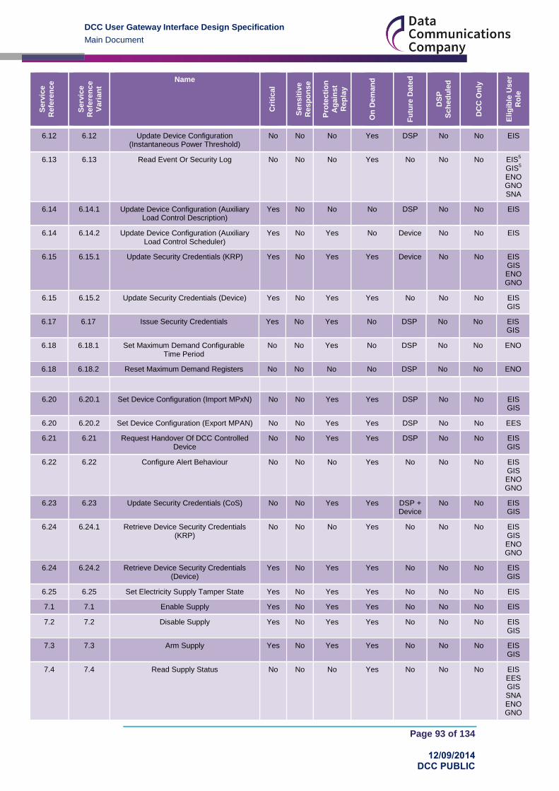
DCC User Gateway Interface Design Specification
Main Document
Page 93 of 134
12/09/2014 DCC PUBLIC
Serv
ice
Refe
ren
ce
Serv
ice
Refe
ren
ce
Vari
an
t
Name
Cri
tical
Sen
sit
ive
Resp
on
se
Pro
tecti
on
Ag
ain
st
Rep
lay
On
Dem
an
d
Fu
ture
Date
d
DS
P
Sch
ed
ule
d
DC
C O
nly
Elig
ible
User
Ro
le
6.12 6.12 Update Device Configuration (Instantaneous Power Threshold)
No No No Yes DSP No No EIS
6.13 6.13 Read Event Or Security Log No No No Yes No No No EIS5
GIS5
ENO GNO SNA
6.14 6.14.1 Update Device Configuration (Auxiliary Load Control Description)
Yes No No No DSP No No EIS
6.14 6.14.2 Update Device Configuration (Auxiliary Load Control Scheduler)
Yes No Yes No Device No No EIS
6.15 6.15.1 Update Security Credentials (KRP) Yes No Yes Yes Device No No EIS GIS ENO GNO
6.15 6.15.2 Update Security Credentials (Device) Yes No Yes Yes No No No EIS GIS
6.17 6.17 Issue Security Credentials Yes No Yes No DSP No No EIS GIS
6.18 6.18.1 Set Maximum Demand Configurable Time Period
No No Yes No DSP No No ENO
6.18 6.18.2 Reset Maximum Demand Registers No No No No DSP No No ENO
6.20 6.20.1 Set Device Configuration (Import MPxN) No No Yes Yes DSP No No EIS GIS
6.20 6.20.2 Set Device Configuration (Export MPAN) No No Yes Yes DSP No No EES
6.21 6.21 Request Handover Of DCC Controlled Device
No No Yes Yes DSP No No EIS GIS
6.22 6.22 Configure Alert Behaviour No No No Yes No No No EIS GIS ENO GNO
6.23 6.23 Update Security Credentials (CoS) No No Yes Yes DSP + Device
No No EIS GIS
6.24 6.24.1 Retrieve Device Security Credentials (KRP)
No No No Yes No No No EIS GIS ENO GNO
6.24 6.24.2 Retrieve Device Security Credentials (Device)
Yes No Yes Yes No No No EIS GIS
6.25 6.25 Set Electricity Supply Tamper State Yes No Yes Yes No No No EIS
7.1 7.1 Enable Supply Yes No Yes Yes No No No EIS
7.2 7.2 Disable Supply Yes No Yes Yes No No No EIS GIS
7.3 7.3 Arm Supply Yes No Yes Yes No No No EIS GIS
7.4 7.4 Read Supply Status No No No Yes No No No EIS EES GIS SNA ENO GNO

DCC User Gateway Interface Design Specification
Main Document
Page 94 of 134
12/09/2014 DCC PUBLIC
Serv
ice
Refe
ren
ce
Serv
ice
Refe
ren
ce
Vari
an
t
Name
Cri
tical
Sen
sit
ive
Resp
on
se
Pro
tecti
on
Ag
ain
st
Rep
lay
On
Dem
an
d
Fu
ture
Date
d
DS
P
Sch
ed
ule
d
DC
C O
nly
Elig
ible
User
Ro
le
7.5 7.5 Activate Auxiliary Load Control Yes No Yes Yes No No No EIS
7.6 7.6
Deactivate Auxiliary Load Control Yes No Yes Yes No No No EIS
7.7 7.7 Read Auxiliary Load Control Switch Data No No No Yes DSP No No EIS OU
7.8 7.8 Reset Auxiliary Load Yes No Yes Yes No No No EIS
7.9 7.9 Add Auxiliary Load To Boost Button No No Yes No
DSP No No EIS
7.10 7.10 Remove Auxiliary Load From Boost Button
No No Yes Yes DSP No No EIS
7.11 7.11 Read Boost Button Details No No No Yes DSP No No EIS OU
7.12 7.12 Set Randomised Offset Limit Yes No Yes No DSP No No EIS
8.1 8.1.1 Commission Device (Synchronise Clock) Yes No Yes Yes No No No EIS GIS
8.1 8.1.2 Commission Device (Set Import MPxN) No No Yes Yes No No No EIS GIS
8.2 8.2 Read Inventory No No No No No No Yes EIS6
EES GIS
6
SNA ENO GNO OU
8.3 8.3 Decommission Device No No No No No No Yes EIS EES GIS
8.4 8.4 Update Inventory No No No No No No Yes EIS EES GIS OU
8.5 8.5 Service Opt Out No No Yes No DSP No No EIS GIS
8.6 8.6 Service Opt In No
No No No No No Yes EIS GIS
8.7 8.7.1 Join Service (Critical) Yes No Yes Yes No No No EIS GIS
8.7 8.7.2 Join Service (Non-Critical) 1 No No Yes Yes No No No EIS
GIS OU
8.8 8.8.1 Unjoin Service (Critical) Yes No Yes Yes No No No EIS GIS
8.8 8.8.2 Unjoin Service (Non-Critical) 1 No No Yes Yes No No No EIS
GIS OU
8.9 8.9 Read Device Log No No No Yes DSP No No EIS GIS OU
8.11 8.11 Update HAN Device Log1
No No Yes Yes DSP No No EIS EES GIS OU

DCC User Gateway Interface Design Specification
Main Document
Page 95 of 134
12/09/2014 DCC PUBLIC
Serv
ice
Refe
ren
ce
Serv
ice
Refe
ren
ce
Vari
an
t
Name
Cri
tical
Sen
sit
ive
Resp
on
se
Pro
tecti
on
Ag
ain
st
Rep
lay
On
Dem
an
d
Fu
ture
Date
d
DS
P
Sch
ed
ule
d
DC
C O
nly
Elig
ible
User
Ro
le
8.12 8.12.1 Restore HAN Device Log No No Yes Yes No No No EIS EES GIS
8.12 8.12.2 Restore GPF Device Log No No Yes Yes No No No GIS
8.13 8.13 Return Local Command Response No No No No No No Yes EIS EES GIS
9.1 9.1 Request Customer Identification Number No No Yes Yes No No No OU
11.1 11.1 Update Firmware No No No No No No Yes2 EIS
GIS
11.2 11.2 Read Firmware Version No No No Yes DSP
No No EIS EES GIS SNA ENO GNO OU
11.3 11.3 Activate Firmware Yes No Yes Yes Device No No EIS GIS
12.1 12.1 Request WAN Matrix No No No No No No Yes EIS EES GIS SNA
12.2 12.2 Device Pre-notification No No No No No No Yes EIS EES GIS
SNA
14.1 14.1 Record Network Data (GAS) No No Yes Yes No Yes No GNO
Table 27 Service Request Matrix
1 Service Request available in relation to Type 2 Devices
2 See section 2.3.10 for details on Firmware Distribution Mode of Operation
5 Service Request also available to the ‘Old’ Registered Supplier
6 Service Request also available to the ‘Pending’ (Future) Registered Supplier
7 Service Request can’t be Sequenced for Gas, because the DCC can’t read the encrypted
status returned by the Device
9.4.1 Commands for Local Delivery
The Command Variant (see section 3) of a Request that sends a Command to a Device indicates if the Command is to be delivered via the SM WAN, returned to the DCC Service User for Local Delivery or both. A Command can be delivered locally:
for all On Demand Requests available to DCC Service User Role EIS, EES or GIS,
where Devices have a status in the Smart Metering Inventory of “Pending”, “Installed
Not Commissioned” or “Commissioned”
and for all On Demand Requests available to the ENO, GNO or OU Service User
Role where Devices have a status of “Installed Not Commissioned” or
“Commissioned” in the Smart Metering Inventory

DCC User Gateway Interface Design Specification
Main Document
Page 96 of 134
12/09/2014 DCC PUBLIC
9.5 Managing Changes to Requests and Responses
It is inevitable that changes to Requests and Responses will be required in the future as a result of the introduction of new services or modifications to existing ones. This section describes the approach that is proposed to allow the management of changes to the XML definitions supported on the DCC User Gateway.
9.5.1 DUGIS XML Schema versions
When changes are made to the XML definitions a new version of the DUGIS XML schema will be published. The schema version is identified by an additional attribute on the root elements, Request and Response, as shown below
<xs:element name="Request">
<xs:complexType> …
<xs:attribute name="schemaVersion" type="xs:decimal" use="required" fixed="2.0"/>
</xs:complexType>
The new schema will support potentially many versions of individual Service Requests and Responses. This is described in section 9.5.2 and 9.5.3. All previous versions of Service Requests and Responses will be carried forward into the new schema version to ensure that all previous functionality of Devices is supported on an ongoing basis.
In order to allow a phased transition to a new schema version across the DCC Service User community, the DCC Data Systems will support both the latest version of the DUGIS XML schema and the immediately preceding version.
9.5.2 Request versions
Where the change to the Request XML definition is driven solely by changes to the overall Request structure (eg changes to Header items) then these changes will be managed by use of the schema version only. That is, the new schema will contain the new definition of the Request, with an updated set of attributes as required. The previous definition will remain in the previous schema and will be supported if a DCC Service User is still using that schema, however once a DCC Service User moves to the new schema they will need to use the new definition.
Where a change to a Service Request specific XML definition is driven by a change to the underlying device protocol specification (eg a change to GBCS) then a different approach must be taken. This is necessary since in this case there is a dependency on the device firmware and the version of the device protocol specification supported by that device firmware. Since this is device specific and the DCC will need to support many variants of device firmware at any one time, the approach to managing these changes will be to support multiple variants of the Service Request XML definition within the same schema.
For example, if a change to GBCS required a change in the Update Supplier Name Service Request then the new schema would be enhanced to include a new version of the UpdateSupplierName XML element with a new name such as UpdateSupplierNameV2. The UpdateSupplierNameV2 XML definition would contain an updated set of attributes as required, whilst the original UpdateSupplierName XML definition would also be available in the new schema with the original set of attributes.

DCC User Gateway Interface Design Specification
Main Document
Page 97 of 134
12/09/2014 DCC PUBLIC
<xs:element name="UpdateSupplierName"> <xs:complexType> <xs:sequence> <xs:element name="SupplierName" type="xs:string"/> <xs:element name="SupplierTelephoneNumber" type="xs:string"/> </xs:sequence> </xs:complexType> </xs:element>
<xs:element name="UpdateSupplierNameV2"> <xs:complexType> <xs:sequence> <xs:element name="SupplierName" type="xs:string"/> <xs:element name="webURL" type="xs:string"/> </xs:sequence> </xs:complexType> </xs:element>
With this approach a DCC Service User can create the appropriate Service Request XML message as required for the device given its device firmware version. This message will use the UpdateSupplierName or UpdateSupplierNameV2 element within its body, but crucially both instances can still use the same Service Reference 3.4 in the header.
As well as the above scenario of modifications to existing Service Request definitions there are a couple of other change scenarios to consider.
The first scenario is the simple case of adding a brand new Service Request. This is relatively straightforward and will result in a new XML definition being added to the new schema. This new Service Request will, of course, have a new Service Reference associated with it.
The second scenario is where there is a change to the underlying device protocol specification but this change does not affect the Service Request XML definition. In this case the DCC Transform Service will simply create the correct version of the underlying GBCS Command based on its knowledge of the device firmware for the device being addressed. Where this scenario occurs for a Critical Service Request then the Pre-Command returned by the Transform Service to the User will include a version indicator so that the Parse and Correlate software can determine which version of the GBCS Command it should be checking against.
Finally, consideration must be given to DCC Only Service Requests and how to manage changes to these Requests. For consistency, these will be handled in the same way as device based Service Requests, ie a new Service Request XML element will be created with a modified “V2” name and the new schema will support this version and any previous versions of that Service Request. The benefit of taking this approach for DCC Only Service Requests is that it allows a DCC Service User to move to the latest version of the DUGIS XML Schema in order to access new device based Service Requests whilst still using the previous versions of DCC Only Service Requests.
9.5.3 Response versions
The handling of changes to Response XML definitions needs to be applied to both the DUGIS XML Schema and the RACI XML Schema.
For the DUGIS XML Schema the approach is similar to that applied for Requests and is described below. For the RACI XML Schema the approach is described in Annex 18.
For the DUGIS XML schema, where the change to the Response XML definition is driven solely by changes to the overall Response structure (eg changes to Header items) then these changes will be managed by use of the schema version only. That is, the new schema

DCC User Gateway Interface Design Specification
Main Document
Page 98 of 134
12/09/2014 DCC PUBLIC
will contain the new definition of the Response, with an updated set of attributes as required. The previous definition will remain in the previous schema and will be supported if a DCC Service User is still using that schema, however once a DCC Service User moves to the new schema they will need to use the new definition. The DCC Data Systems will determine which version of the Response to return to the DCC Service User based on the schema version used in the corresponding Request.
Where a change to a DCC Only Service Response specific XML definition is driven by a change to the specific data items of that Service Response then a new XML element definition will be created with a modified “V2” name and the new schema will support this version and any previous versions of that Service Response. The DCC Data Systems will determine which version of the Service Response to return to the DCC Service User based on the schema version and XML element name used in the corresponding Service Request.
Where a change to the underlying device protocol changes the content of the GBCS Response then this has no impact on the DUGIS XML Schema definition, but it will be handled by the RACI XML schema (see Annex 18).

DCC User Gateway Interface Design Specification
Main Document
Page 99 of 134
12/09/2014 DCC PUBLIC
10 Web Services Implementation
10.1 Technical Implementation
The technical implementation of the DCC User Gateway Interface is provided by using “web services” to allow Requests and Responses to be sent between the DCC Data Systems and the systems of the DCC Service Users.
The DCC User Gateway accepts Service Requests or Signed Pre-Commands as XML documents submitted using an HTTP POST command. (Note this should not be confused with a SOAP based web service). Similarly, when data is pushed from the DCC User Gateway to a DCC Service User, the DCC Service User needs to provide a web server to accept POSTed data. The content of this POST command will be either a Service Response (from Device), a Command for Local Delivery (asynchronous), a Device Alert or a DCC Alert message.
The POST command is an HTTP protocol method to request that the addressed web server accepts the data enclosed in the message’s body for processing. The web server responds with an HTTP response, which may also include data in the message body.
The contents of all the POSTed commands and any HTTP response data is XML, and is defined by the DUGIS XML schema. The interface utilises HTTP status codes within the HTTP response to communicate the success or failure of the call.
To process Requests, there are three services provided by the DCC Data Systems as follows:
Transform Service – a service to solely provide the transformation of Critical Service
Requests to GBCS format and return a Pre-Command to the DCC Service User.
DCC Only Service – a service to handle those Service Requests that only require
interaction with the DCC Data Systems.
Send Command Service – a service to send a Non-Critical Service Request or
signed Pre-Command (for Critical Service Requests) to a specified Device.
The Transform and DCC Only web services follow a synchronous processing pattern and return Service Response data to DCC Service Users within the HTTP response.
The Send Command web service also completes synchronously and returns an HTTP response, but this response simply provides an Acknowledgement to indicate acceptance of the Service Request by the DCC.
Figure 58 illustrates the synchronous pattern. Note that the submitted request is defined by the XML object Request, The DCC Data Systems synchronously responds to the submission with an appropriate HTTP Status Code and XML Response content. The content of the synchronous Response is an Acknowledgement, a Pre-Command, a Command for Local Delivery or a Service Response (from DCC) as defined in section 9.3.1.
Figure 58 Service Request from Service User to the DCC
To receive asynchronous Service Responses and Alerts, the DCC Service User system must implement a web service as follows:

DCC User Gateway Interface Design Specification
Main Document
Page 100 of 134
12/09/2014 DCC PUBLIC
Receive Response Service – a service to receive Service Responses and Alerts from the DCC Data Systems.
To implement this service, the Service User is required to provide a URL for a web server that will accept the HTTP POSTed XML (HTTP version 1.1) from the DCC Data Systems. The URL details are to be defined by the Service User and provided to the DCC as described in the Code of Connection for the DCC User Gateway Interface. It is the Service User’s responsibility to ensure that this URL is available to receive data from the DCC Data Systems.
Figure 59 illustrates the asynchronous pattern. The structure of the POST command is defined by the Response XML object. The content of the asynchronous Response is a Service Response (from Device), a Command for Local Delivery, a Device Alert or a DCC Alert as defined in section 9.3.1. The Service User responds back to the DCC with an HTTP response containing the appropriate HTTP status code to indicate whether the call was successful or not. Failure to receive an HTTP response will invoke the DCC retry behaviour as described in section 11.6.
Figure 59 Service Response from the DCC to the Service User
10.2 URI Naming and API Versioning
URI names will be provided to DCC Service Users as part of the process of obtaining a connection to the DCC User Gateway. Names used in this section are examples to help show the principles of API versioning.
The DCC User Gateway Interface provides a capability to manage the transition from one version of the interface definition to the next. DCC Service Users can choose to upgrade at a later date than at the point when the User Gateway components are cut over to a new version of the published API. Support for the old version of the API and for the new version will continue until customers have completed their upgrade and cut-over tasks.
The endpoints for the service are named as follows:
Web Service URI for Message Gateway Request Comment
DCC Only Service http://api.mycorp.com/serviceD/ For services only requiring interaction with DCC Data Systems
Transform Service http://api.mycorp.com/ServiceT/ For transformation of Critical Service Requests to Pre-commands
Send Command Service
http://api.mycorp.com/serviceS/ For sending a non-critical Service Request or signed Pre-command (for Critical Service Requests) to the device
Table 28 URI Naming
The Message Gateway services are identified with a separate document root/sub-domain “api” because this approach allows digital certificates to be managed separately to those used for other parts of the DCC domain, and because it is compatible with recommendations on service design in the Government Service Design Manual.

DCC User Gateway Interface Design Specification
Main Document
Page 101 of 134
12/09/2014 DCC PUBLIC
The design of URIs for the Message Gateway is based on the principle that components naming should have as few natural constraints as possible, and should be preserved over time, reflecting a long-term commitment to users of the API. The HTTP Protocol provides features for negotiation of the version of a document type to be returned from the server to a client, and is the basis for meeting the requirement for versioning.
Here is an example of how requests will be handled when an API is at version 2.0, with
previous published versions at 0.9 (no longer supported) and 1.0 (used by older clients, but support will be obsoleted when version 3.0 of the API goes live):
http://api.mycorp.com/0.9/serviceD/ // Obsolete, HTTP 30x redirect to 1.0 sent http://api.mycorp.com/1.0/serviceD/ // Deprecated, but still acceptable – v 1.0 of API used http://api.mycorp.com//2/serviceD/ // Explicit request for latest version of API http://api.mycorp.com/2.0/serviceD/ // Alternative form of request for latest version of API http://api.mycorp.com/serviceD/ // Preferred form of request for latest version of API
In the box above, the first line contains an obsolete URI, which the server will respond to with a redirect to version 1.0 of the API, which is deprecated but still supported. The second line contains a deprecated but still supported API, which does not generate a redirect request.
The final line contains the version-free API base URI. This points to the current version of the API (version 2.0), and is equivalent to the two preceding lines. This is the preferred URI for using the web service.
Accessing an obsolete URI may return any of the 30x HTTP status codes that indicate
redirection in conjunction with the Location HTTP header that redirects to the appropriate
latest version of the resource URI.
The redirection codes to be used for this implementation will be
301 Moved Permanently: pointing to the version-less URI
302 Found: used when the latest version of the API is temporarily not available but the client is being directed to keep trying it for future attempts
Other redirection codes are described in section 10.3 of http://www.w3.org/Protocols/rfc2616/rfc2616-sec10.html
The rationale for this approach is that, over time, new resources and new attributes for each resource may be defined but the method used to access a particular resource will not change once the resource addressing scheme becomes public (and final, in the sense that any changes will require a re-write of the client side of the interface).
It is feasible to embed the API version in the base URI, but this makes the history of the versioning of the API visible/apparent and therefore prone to changes from the maintainer’s point of view; a better approach is to use version information in URIs for reasonable and limited uses (such as debugging during development) and to implement the latest API version under a version-free API base URI, at the same time informing clients that an upgrade is available and advisable (if they are using a deprecated version) or mandatory (if the version they have requested is now obsolete).
10.3 Content Negotiation
In addition to redirecting obsolete requests to the most appropriate URI that can handle them (discussed in the previous section), the service allows for the version of an API to be used to be negotiated between the client and the server.
The HTTP specification (RFC 2616) describes content negotiation as being “the process of selecting the best representation for a given response when there are multiple representations available”. The mechanism for content negotiation in HTTP is provided by these request headers:

DCC User Gateway Interface Design Specification
Main Document
Page 102 of 134
12/09/2014 DCC PUBLIC
Accept: Which media types are acceptable for the response, such as
“application/json,” “application/xml,” or a custom media type such as
"application/vnd.example+xml"
Accept-Charset: Which character sets are acceptable, such as UTF-8 or ISO 8859-1.
Accept-Encoding: Which content encodings are acceptable, such as gzip.
Accept-Language: The preferred natural language, such as “en-us”.
There is no built-in support in the API for the Accept-Encoding or Accept-Language headers, but the Message Gateway and its clients may use the custom media type mechanism defined for the Accept header to negotiate which version of a resource to exchange. The media type defined for the Message Gateway is “application/vnd.dcc-vx.y+xml”, where the
characters x and y stand for the major and minor version numbers of the API version being
negotiated. The Location: header is used by the server to point the client to the corrected
URI for the request if the requested version is still available to be used.
An example of this in practice would be as follows:
Client request:
POST /serviceD HTTP/1.1
ACCEPT application/vnd-dcc-1.0+xml
Host: api.mycorp.com
Server response:
HTTP/1.1 302 Found
Location: http://api.mycorp.com/1.0/serviceD

DCC User Gateway Interface Design Specification
Main Document
Page 103 of 134
12/09/2014 DCC PUBLIC
11 Error Handling A submitted Service Request or Signed Pre-command may not be successfully processed by the DCC Data Systems due to a number of reasons. From the point that the Service Request or Signed Pre-command is accepted by the DCC Data Systems, the DCC Data Systems are responsible for (as applicable depending on its Command Variant – see section 3):
sending the Command to the CSP
returning the Command to the DCC Service User for Local Delivery
returning the Pre-command to the DCC Service User
returning the Service Response to the DCC Service User
This section describes the Error Handling and Retry Strategy implemented in the DCC User Gateway.
11.1 Error Handling
Errors encountered when processing a Service Request or Signed Pre-command, which cannot be resolved by the retry strategy, are passed back to the original DCC Service User who requested the service.
Errors may be caused by an incomplete or invalid Service Request or Signed Pre-command (see section 7), due to failure to deliver the GBCS message to the Device, or failures to process a request within the DCC Data System processing
The Response Code contained in the Acknowledgement or Service Response message will indicate the failure type. See section 12.3 for more details on DCC Data Systems Response Codes.
11.2 Retry Strategy
For those Commands that are to be delivered to a Device via the CSP, the DCC Data Systems will at the point of execution attempt to deliver the GBCS Command to the device’s communications hub via the appointed CSP provider.
Should it not be possible to deliver the Command (i.e. if there is an error reported during the delivery processing), then the DCC Data Systems shall attempt to redeliver the message at a later time. The redelivery is controlled by an algorithm with a “back-off” period and a maximum number of retries before eventually failing. Should the delivery fail after the final attempt, then a failure message is returned to the DCC Service User via a DCC Alert with an appropriate Response Code as defined in section 12.3.
In a similar fashion, if the Command is delivered (i.e. there are no errors reported during delivery processing) but no response is received within a configurable timeout period then the DCC Data Systems will attempt to redeliver the message at a later time. Again, the redelivery is controlled by an algorithm with a “back-off” period and a maximum number of retries before eventually failing and returning a failure message to the DCC Service User via a DCC Alert with an appropriate Response Code as defined in section 12.3.
The retry approach for different Modes of Operation are described further in section 11.6.
Note that in all cases, the DCC Data Systems will re-send the Command with the same Request ID. This ensures that in the event that the Command is actually received by the Device then the anti-replay features of the GBCS will ensure that the Command is not executed twice.
11.3 Unfulfilled Requests
The DCC Data Systems shall monitor Service Requests and Signed Pre-Commands to ensure that a Service Response is received by DCC Service Users as expected.

DCC User Gateway Interface Design Specification
Main Document
Page 104 of 134
12/09/2014 DCC PUBLIC
For “On Demand” Service Requests or Signed Pre-Commands, if no response is received after a configurable period, a DCC Alert with an appropriate response code and the original Request ID for which there was no response from the device will be returned to the DCC Service User.
For “Future Dated (Device)” Service Requests or Signed Pre-Commands, if no response is received after a configurable period beyond the Execution Date Time, a DCC Alert with an appropriate response code and the original Request ID for which there was no response from the device will be returned to the DCC Service User.
For “Future Dated (DSP)” Service Requests, where a response to the future dated request is not received, then the retry strategy will be initiated. If there is no response after the retries, a DCC Alert with an appropriate response code and the original Request ID for which there was no response from the device will be returned to the DCC Service User.
For “DSP Scheduled” Service Requests, where a response to the scheduled request is not received, then the retry strategy will be initiated. If there is no response after the retries, a DCC Alert with an appropriate response code and the Schedule ID for which there was no response from the device will be returned to the DCC Service User. The lack of response to a “DSP Scheduled” Service Request doesn’t affect the DSP Schedule, which will continue to run until its defined End Date or until it is deleted.
For the avoidance of doubt, no DCC Alerts with timeout response codes will be issued by the DCC Data Systems for “Transform” or “DCC Only” where the DCC Service User is expected to ensure that a Service Response is received from the DCC and take any appropriate remedial action required.
11.4 Failure to deliver Responses to DCC Service Users
If the DCC Data Systems has received a Service Response or Alert from a Device or generated a DCC Alert, but is unable to deliver that Service Response, Device Alert or DCC Alert to the DCC Service User (e.g. due to unavailability of the Service User’s systems) then the DCC Data Systems will attempt to redeliver the message at a later time. The redelivery is controlled by an algorithm with a “back-off” period and a maximum number of retries before eventually failing.
Note that in this case the retry configuration will be such that the DCC Data Systems will retry for a significant period of time before ultimately recording a failure to deliver in the Service Audit Log.
11.5 Web Services Error Handling
All web service interactions between DCC Service Users and the DCC Data Systems follow a synchronous processing pattern for the individual web service call.
For the “Transform Service” and “DCC Only Service” web services, the synchronous completion of the web service call returns the Service Response to the DCC Service User. This Service Response will contain a response code (error code) if there have been any errors in processing the request.
For the “Send Command Service” web service, the synchronous completion of the web service call returns an Acknowledgement to the DCC Service User. This Acknowledgement will contain a response code (error code) if there have been any errors in processing the request (e.g. access control failure).
In a similar fashion the synchronous completion of the “Receive Response Service” web service call returns an http “acknowledgement” to the DCC Data Systems. This http acknowledgement will contain a response code (error code) if there have been any errors in processing the request (e.g. a data or validation failure).
In all cases, the web service client implementation should utilise an appropriate timeout to handle any failure to complete the service call.
See section 12 for more details on response codes returned by individual web services.

DCC User Gateway Interface Design Specification
Main Document
Page 105 of 134
12/09/2014 DCC PUBLIC
11.6 Service Request and Response Error Handling
The following sections describe the error handling and retry behaviour for each mode of operation of Service Request/Response processing (see section 2.3)
Note that all retry periods and timeout values are configurable items and may be subject to change as part of an agreed Service Management process. Some values are dependent on Mode of Operation and Target Response Times. These are described in Table 29. Other values are fixed in all cases and these have initial proposed values in square brackets within the following sections.
Mode of Operation Initial Retry Period Back-off period Final Retry Period
On Demand 2 x On Demand Target Response Time
n/a n/a
Future Dated (Device)
2 x On Demand Target Response Time
2 hours Future Dated (Device) Target Response Time + 60 mins
Future Dated (DSP)
2 x On Demand Target Response Time
2 hours Future Dated (DSP) Target Response Time + 60 mins
DSP Scheduled 2 x On Demand Target Response Time
2 hours DSP Scheduled Target Response Time + 60 mins
Table 29 Retry Periods
11.6.1 Transform and DCC Only
Error Scenario Behaviour
DCC Service unavailable DCC Service User retry as appropriate for Service Reference and Target Response Time
If DCC Service persistently unavailable, then raise Service Management Incident against DCC User Gateway
Invalid request or Access Control failure
Acknowledgement returned on synchronous web service completion with appropriate Response Code (reason for error). See section 12.3
Table 30 Error Handling– - Transform and DCC Only
11.6.2 On Demand
Error Scenario Behaviour
DCC Service unavailable DCC Service User retry as appropriate for Service Reference and Target Response Time
If DCC Service persistently unavailable, then raise Service Management Incident against DCC User Gateway
Invalid request or Access Acknowledgement returned on synchronous web

DCC User Gateway Interface Design Specification
Main Document
Page 106 of 134
12/09/2014 DCC PUBLIC
Error Scenario Behaviour
Control failure service completion with appropriate Response Code (reason for error). See section 12.3
Failure to send command over SM WAN
DCC to retry at least once within Service Reference Target Response Time
If failed after further retries and expiry of initial retry period (see Table 29) then return DCC Alert N12 with appropriate Response code to requesting DCC Service User
Failure to receive response over SM WAN
DCC to retry at least once within Service Reference Target Response Time
If nothing received after further retries and expiry of initial retry period (see Table 29) mark as failed and return DCC Alert N13 with appropriate Response code to requesting DCC Service User,
If the response is received after the failure notification, it will be flagged as anomalous (since there is no outstanding request against it) and recorded as a Service Management Event
Unable to deliver response to Service User
DCC retry at regular intervals.
If failed after [300 secs] from first DCC attempt to deliver response to Service User then place on “failed” queue for re-delivery once DCC Service User connection restored.
Failed responses will be held for [2 days] for re-sending once DCC Service User Connectivity is restored.
The Service Management Framework will define the processes to be followed for long term unavailability of Service User connectivity, including how long data can be held for.
Table 31 Error Handling – On Demand
11.6.3 Future Dated (Device)
Error Scenario Behaviour
DCC Service unavailable DCC Service User retry as appropriate for Service Reference and Target Response Time
If DCC Service persistently unavailable, then raise Service Management Incident against DCC User Gateway
Invalid request or Access Control failure
Acknowledgement returned on synchronous web service completion with appropriate Response code to requesting DCC Service User.

DCC User Gateway Interface Design Specification
Main Document
Page 107 of 134
12/09/2014 DCC PUBLIC
Error Scenario Behaviour
Failure to send command over SM WAN
DCC retry at least once within initial retry period (see Table 29).
If failed after further retries and expiry of initial retry period then place on “redelivery” queue for subsequent re-send after back-off period (see Table 29).
If failed after multiple re-delivery attempts up to expiry of final retry period (see Table 29) then return DCC Alert N12 with appropriate Response code to requesting DCC Service User.
Failure to receive Command Acknowledgement response over SM WAN
DCC retry at least once within initial retry period (see Table 29).
If nothing received after further retries and expiry of initial retry period place on “redelivery” queue for subsequent re-send after back-off period (see Table 29).
If failed after multiple re-delivery attempts up to expiry of final retry period (see Table 29) then return DCC Alert N13 with appropriate Response code to requesting DCC Service User.
No Future Service Response received from Device
For all future dated commands acknowledged by the Device, if no response received from the specified Device within the Target Response Time after the execution date and time contained within the original Service Request then DCC to return DCC Alert N10 to the DCC Service User with a “Timeout” Response Code.
If the response is received after the Timeout, it will be flagged as anomalous (since there is no outstanding request against it) and recorded as a Service Management Event.
Unable to deliver response to Service User
DCC retry at regular intervals.
If failed after [300 secs] from first DCC attempt to deliver response to Service User then place on “failed” queue for re-delivery once DCC Service User connection restored.
Failed responses will be held for [2 days] for re-sending once DCC Service User Connectivity is restored.
The Service Management Framework will define the processes to be followed for long term unavailability of Service User connectivity, including how long data can be held for.
Table 32 Error Handling – Future Dated (Meter)

DCC User Gateway Interface Design Specification
Main Document
Page 108 of 134
12/09/2014 DCC PUBLIC
11.6.4 Future Dated (DSP)
Error Scenario Behaviour
DCC Service unavailable DCC Service User retry as appropriate for Service Reference and Target Response Time.
If DCC Service persistently unavailable, then raise Service Management Incident against DCC User Gateway
Invalid request or Access Control failure
Acknowledgement returned on synchronous web service completion with appropriate Response code to requesting DCC Service User.
Access Control failure at Future Dated execution time
DCC Alert N7 returned with appropriate Response Code.
Failure to send Request over SM WAN
DCC retry at least once within initial retry period (see Table 29) from first delivery attempt .
If failed after further retries and expiry of initial retry period then place on “redelivery” queue for subsequent re-send after back-off period (see Table 29).
If failed after multiple re-delivery attempts up to expiry of final retry period (see Table 29) from requested execution time then return DCC Alert N12 to the DCC Service User with a “Timeout” Response Code.
Failure to receive response over SM WAN
DCC retry at least once within initial retry period (see Table 29) from first delivery attempt ..
If nothing received after further retries and expiry of initial retry period place on “redelivery” queue for subsequent re-send after back-off period (see Table 29).
If failed after multiple re-delivery attempts up to expiry of final retry period (see Table 29) from requested execution time then return DCC Alert N11 to the DCC Service User with a “Timeout” Response Code.
If the response is received after the Timeout, it will be flagged as anomalous (since there is no outstanding request against it) and recorded as a Service Management Event.

DCC User Gateway Interface Design Specification
Main Document
Page 109 of 134
12/09/2014 DCC PUBLIC
Error Scenario Behaviour
Unable to deliver response to Service User
DCC retry at regular intervals.
If failed after [300 secs] from first DCC attempt to deliver response to Service User then place on “failed” queue for re-delivery once Service User connection restored.
Failed responses will be held for [2 days] for re-sending once DCC Service User Connectivity is restored.
The Service Management Framework will define the processes to be followed for long term unavailability of Service User connectivity, including how long data can be held for.
Table 33 Error Handling – Future Dated (DSP)
11.6.5 DSP Scheduled
Error Scenario Behaviour
Validation or Access Control failure at Scheduled execution time
DCC Alert N7 returned with appropriate Response Code.
Failure to send Request over SM WAN
DCC retry at least once within initial retry period (see Table 29) from first delivery attempt .
If failed after further retries and expiry of initial retry period then place on “redelivery” queue for subsequent re-send after back-off period (see Table 29).
If failed after multiple re-delivery attempts up to expiry of final retry period (see Table 29) from requested execution time then return DCC Alert N11 to the DCC Service User with a “Timeout” Response Code.
Failure to receive response over SM WAN
DCC retry at least once within initial retry period (see Table 29) from first delivery attempt ..
If nothing received after further retries and expiry of initial retry period place on “redelivery” queue for subsequent re-send after back-off period (see Table 29).
If failed after multiple re-delivery attempts up to expiry of final retry period (see Table 29) from requested execution time then return DCC Alert N11 to the DCC Service User with a “Timeout” Response Code.
If the response is received after the Timeout, it will be flagged as anomalous (since there is no outstanding request against it) and recorded as a Service Management Event.

DCC User Gateway Interface Design Specification
Main Document
Page 110 of 134
12/09/2014 DCC PUBLIC
Error Scenario Behaviour
Unable to deliver response to Service User
DCC retry at regular intervals.
If failed after [300 secs] from first DCC attempt to deliver response to Service User then place on “failed” queue for re-delivery once Service User connection restored.
Failed responses will be held for [2 days] for re-sending once DCC Service User Connectivity is restored.
The Service Management Framework will define the processes to be followed for long term unavailability of Service User connectivity, including how long data can be held for.
Table 34 Error Handling – DSP Scheduled
11.6.6 Meter Scheduled
Error Scenario Behaviour
DCC Service User fails to receive response from DCC at scheduled time
This is a DCC Service User Responsibility.
Suggestion– - If nothing received after [24 hours] from expected receipt time DCC Service User to initiate Service Request to retrieve Billing Data OR initiate Service Request to read Smart Meter Device log
Unable to deliver response to Service User
DCC retry at regular intervals.
If failed after [300 secs] from first DCC attempt to deliver response to Service User then place on “failed” queue for re-delivery once DCC Service User connection restored.
Failed responses will be held for [2 days] for re-sending once DCC Service User Connectivity is restored.
The Service Management Framework will define the processes to be followed for long term unavailability of Service User connectivity, including how long data can be held for.
Table 35 Error Handling – Meter Scheduled
11.6.7 Device Alert
Error Scenario Behaviour
Unable to deliver response to Service User
DCC retry at regular intervals.
If failed after [300 secs] from first DCC attempt to deliver response to Service User then place on “failed” queue for re-delivery once DCC Service User connection restored.
Failed Alerts will be held for [2 days] for re-sending once DCC Service User Connectivity is

DCC User Gateway Interface Design Specification
Main Document
Page 111 of 134
12/09/2014 DCC PUBLIC
Error Scenario Behaviour
restored.
The Service Management Framework will define the processes to be followed for long term unavailability of Service User connectivity, including how long data can be held for.
Table 36 Error Handling – Device Alert
11.6.8 DCC Alert
Error Scenario Behaviour
Unable to deliver response to Service User
DCC retry at regular intervals.
If failed after [300 secs] from first DCC attempt to deliver response to Service User then place on “failed” queue for re-delivery once DCC Service User connection restored.
Failed Alerts will be held for [2 days] for re-sending once DCC Service User Connectivity is restored.
The Service Management Framework will define the processes to be followed for long term unavailability of Service User connectivity, including how long data can be held for.
Table 37 Error Handling – DCC Alert

DCC User Gateway Interface Design Specification
Main Document
Page 112 of 134
12/09/2014 DCC PUBLIC
12 Response and Status Codes This section defines the Response Codes and the HTTP status codes (see http://www.w3.org/Protocols/rfc2616/rfc2616-sec10.html) returned by the DCC Data Systems to the DCC Service User Systems in response to a Transform Service, DCC Only Service or Send Command Service web service call, and those to be returned by the DCC Service User Systems to the DCC Data Systems in response to a Receive Response web service call.
12.1 DCC Data Systems Web Service Status Codes
When the DCC Service Users call the DCC Data Systems web services, the DCC Data Systems return a response. HTTP status codes are used to indicate success or failure of the web service call:
200: The message has been processed. Please note that the business status code is included within the content of the response.
300: The recipient requires that the client redirect its request to the alternative URI provided in the Location header field.
400. Bad Request – Indicates that the syntax of the request is invalid and the DCC Data Systems are unable to parse the request. The status code in the returned HTTP response provides further information about the error.
500. Internal Server Error – Indicates that the DCC Data Systems are malfunctioning.
503. Service Unavailable – The DCC Data Systems server is currently unavailable (because it is overloaded or down for maintenance). This is typically returned when there are no resources (routes, queues, etc.) to service the request.
12.2 DCC Service User Web Service Status Codes
When DCC calls the DCC Service Users Receive Response web service, the DCC Service User returns an acknowledgement response. HTTP status codes are used to indicate success or failure of the web service call:
200: The message has been accepted.
300: The recipient requires that the client redirect its request to the alternative URI provided in the Location header field.
400. Bad Request – Indicates that the syntax of the request is invalid and the DCC Service User system is unable to parse the request. The status code in the returned HTTP response provides further information about the error.
500. Internal Server Error – Indicates that a DCC Service User system is malfunctioning.
503. Service Unavailable – The DCC Service User server is currently unavailable (because it is overloaded or down for maintenance). This is typically returned when there are no resources (routes, queues, etc.) to service the request.
12.3 DCC Data Systems Response Codes
This section specifies the meaning associated with the DCC Data Systems generic Response Codes within the response message. The Service Request specific Response Codes are included in the Annex.
All responses to the DCC Service User include a Response Code.
Error Response Codes are the result of:
Access Control Second Step Authentication failures

DCC User Gateway Interface Design Specification
Main Document
Page 113 of 134
12/09/2014 DCC PUBLIC
Access Control Authorisation failures
Access Control Validation failures
Failure to send a command to a Device or receive a response from it
“Future Dated” and “DSP Scheduled” command time-outs
Sequencing Failures
All Device Responses will include an ‘I0’ (success) Response Code, meaning that the DCC Data Systems have received a response from the Device. The error code (success / failure) of each GBCS Command in the Device response will be included in the GBCS payload message. These GBCS error codes are not documented here but they are documented in the GBCS itself..
A Response Code consists of a letter prefix (defining the type) followed by a number. Response Code Types:
Information. Prefix ‘I’
Error. Prefix ‘E’
Warning. Prefix ‘W’
Response Code Response Code Name
Response Code Type
Description Applicable to
Response Types
I0 Success Information Request has had a successful outcome All
I99 Acknowledgement Information Request received for sending to Device has been accepted and is correct
Acknowledgement
E1 Failed Authorisation –
Invalid User / User Role
Error DCC Service User / User Role combination is not a valid SEC party / User Role
Acknowledgement and DCC Alerts
E2 Failed Authorisation – Invalid User Role / Service Reference
Error DCC Service User Role not allowed to call Service Reference
Acknowledgement
E3 Failed Authorisation – Invalid User Status
Error DCC Service User Status not allowed to call Service Reference
Acknowledgement and DCC Alerts
E4 Failed Authorisation – Invalid User / User Role
for Device
Error DCC Service User Role not authorised party for Device and required date & time
Acknowledgement and DCC Alerts
E5 Failed Authorisation – Invalid Device Status
Error Device status incompatible with Service Reference
Acknowledgement and DCC Alerts
E11 Failed Validation – Invalid Service Request
/ device type combination
Error Service Reference not compatible with the specified device
Acknowledgement
E12 Failed Validation – Invalid Request /
Command Variant combination
Error Command Variant not applicable to the Request type
Acknowledgement
E13 Failed Validation – Invalid Request Type for
URL
Error Request Type not valid for the URL, e.g. a “DCC Only” Service Request sent to the “Transform” URL
Acknowledgement
E17 Failed Authorisation – Invalid DCC User Role /
Device for locally delivered Commands
Error DCC User Role / Device status combination doesn’t allow Request of Command for local delivery
Acknowledgement

DCC User Gateway Interface Design Specification
Main Document
Page 114 of 134
12/09/2014 DCC PUBLIC
Response Code Response Code Name
Response Code Type
Description Applicable to
Response Types
E19 Failed Authorisation– - Device doesn’t exist
Error Device ID invalid Acknowledgement
E20 Communications Failure – Unable to
Communicate with Device
Error DCC Data Systems cannot establish communications with Device
DCC Alerts
E21 Communications Failure – No Response
Received from Device
Error No response received from Device for an “On Demand” Command or a “Future Dated” Command Acknowledgement
DCC Alerts
E30 Time-out – “Future Dated” Command
Error DCC Data Systems don’t get response from Device on the expected date for “Future Dated” command
DCC Alerts
E31 Time-out – “DSP Schedule” /“Future
Dated (DSP) Command
Error DCC Data Systems cannot establish communications with or get response from Device for “DSP Scheduled” or “Future Dated (DSP) command
DCC Alerts
E40 Failed Sequenced Command – Invalid First
Request
Error DCC Data Systems fail sequenced Request because it includes the First In Sequence flag set to true and the Preceding RequestID is populated
Acknowledgement
E41 Failed Sequenced Command – Invalid
Preceding Request ID
Error DCC Data Systems fail sequenced Request, because its Preceding Request ID is also the Preceding RequestID of another Request in the same sequence
Acknowledgement
E42 Failed Sequenced Command – Circular
Reference
Error DCC Data Systems fail sequenced Request, because its Request ID is the same as its Preceding Request ID or the Preceding RequestID of its preceding request or of one of its preceding requests, e.g. request id 1 has request 2 as its preceding request and request 2 has request 1 as its preceding request
Acknowledgement
E43 Failed Sequenced Command – Previous
Request(s) Failure
Error DCC Data Systems fail sequenced Request, because previous Request (s) in the sequence failed
Acknowledgement and DCC Alerts
E44 Failed Sequenced Command – Previous
Request(s) not received
Error DCC Data Systems fail sequenced Request, because previous Request(s) in the sequence not received during “Wait Period”
Acknowledgement and DCC Alerts
E45 Failed Sequenced Command – Invalid Command Variant
Error DCC Data Systems fail sequenced Request, because its Command Variant is not applicable to a sequenced Request
Acknowledgement
E46 Failed Sequenced Command – Request
after Last In Sequence
Error DCC Data Systems fail sequenced Request, because it is dependent on the Last In Sequence
Acknowledgement and DCC Alerts
E47 Failed Sequenced Command – Request
failed because no response to “On
Demand” Command received from device
Error DCC Data Systems fail sequenced Request, because no response received from device to “On Demand” Command
Acknowledgement and DCC Alerts
E48 Failed Validation – Service Request
Reference and Variant mismatch
Error Invalid combination of Service Reference and Service Reference Variant
Acknowledgement
E49 Failed Validation – Service Request Format and Service Reference
Variant mismatch
Error The Service Request format doesn’t match the Service Reference Variant in the message header
Acknowledgement

DCC User Gateway Interface Design Specification
Main Document
Page 115 of 134
12/09/2014 DCC PUBLIC
Response Code Response Code Name
Response Code Type
Description Applicable to
Response Types
E50 Local Command Services Not Returned
Error The Service Request asking for a Command for Local Delivery has been quarantined
Acknowledgement
E51 Failed Validation – Signed Pre-Command
Message Code and Service Reference Variant mismatch
Error The GBCS Message Code in the Signed Pre-Command GBCS Payload doesn’t map to the Service Reference Variant in the Signed Pre-Command XML header
Acknowledgement
E100 Failed Authentication Error Request failed Authentication second step (this means Authentication failed internally to the DCC Data Systems, having passed the initial authentication at the external boundary).
Acknowledgement
Table 38 DCC Data Systems Response Codes

DCC User Gateway Interface Design Specification
Main Document
Page 116 of 134
12/09/2014 DCC PUBLIC
13 DCC Alerts The list of DCC Alerts is as follows:
DCC Alert Code
Alert Name Event
Trigger DCC Alert Recipient
AD1 Power Outage Event Power Outage Event received from CSP
CSP notification of loss of mains power as detected at the Communications Hub in the Consumer Premises for a time equal to or greater than three (3) minutes
Registered EIS1
Registered ENO1
Registered GIS2
Registered GNO2
N1 Electricity Smart Meter Decommission or withdrawal
Decommissioning or withdrawal of an Electricity Smart Meter Device
Upon successful completion of Service Request:
8.3 Decommission Device
Or 8.5 Service Opt Out
for an Electricity Smart Meter Device
Registered ENO and, if applicable, registered EES
N2 Gas Smart Meter Decommission or withdrawal
Decommissioning or withdrawal of Gas Smart Meter Device
Upon successful completion of Service Request:
8.3 Decommission Device
Or 8.5 Service Opt Out
for a Gas Smart Meter Device
Registered GNO
N3 Cancellation of “Future Dated (DSP)” requests because of CoT
Cancellation of “Other User” “Future Dated (DSP)” Services not yet submitted to the Device
Upon successful completion of Service Request 3.2 Restrict Access for Change of Tenancy
Request sender
N4 Schedule removal because of CoT
Removal of “Other User” “DSP Scheduled” schedules
Upon successful completion of Service Request 3.2 Restrict Access for Change of Tenancy
All applicable Schedule “owners”
N5 Schedule removal because of Device withdrawal
“DSP Scheduled” schedule removal
Upon successful completion of Service Request 8.5 Service Opt Out for a Device
All applicable Schedule “owners”
N6 Schedule removal because of Device decommission
“DSP Scheduled” schedule removal
Upon successful completion of Service Request 8.3 Decommission Device for a Device
All applicable Schedule “owners”
N7 “DSP Scheduled” / “Future Dated (DSP)” access control failure
“DSP Scheduled” / “Future Dated (DSP)” access control failure (Authorisation, Device status)
“DSP Scheduled” / “Future Dated (DSP)” Command generation access control failure
Schedule “owner” / “Future Dated (DSP) request sender
N8 Device removed from Inventory- Pending Status expired
Removal of Device from Inventory
Device in a status of ‘pending’ for > 12 months
Original DCC Service User that requested addition of the Device to the DCC Inventory
N9 Communications Hub Decommission
Decommission of Communications Hub
Upon successful completion of Service Request 8.3 Decommission Device for a Communications Hub
All Responsible Suppliers for that CH function, other than the Responsible EIS / GIS that instigated the Decommissioning
Registered ENO
Registered GNO
N10 “Future Dated (Device)” command time-out
“Future Dated(Device)” command time-out
“Future Dated (Device)” command response not received from the device within the Target Response Time from the ExecutionDateTime
“Future Dated (Device)” request sender

DCC User Gateway Interface Design Specification
Main Document
Page 117 of 134
12/09/2014 DCC PUBLIC
DCC Alert Code
Alert Name Event
Trigger DCC Alert Recipient
N11 “DSP Scheduled” / “Future Dated (DSP)” command time-out
“DSP Scheduled” / “Future Dated (DSP)” command time-out
“DSP Scheduled” Schedule instance / “Future Dated (DSP)” command not sent to or response not received from the Device within the Target Response Time from the ExecutionDateTime
Schedule “owner” / “Future Dated (DSP) request sender
N12 Failure to deliver command to Device
Failure to deliver command to Device
Failure to receive an acknowledgement notification from a CSP via the SM WAN for an “On Demand” or “Future Dated” Command
Request sender
N13 Failure to receive response from Device
Failure to receive response from Device
Failure to receive a response from a Device for an “On Demand” Command or “Future Dated” Command Acknowledgement
Request sender
N14 Sequenced Request Failure Sequenced Request Failure Previous Command in sequence failed or timed-out
Request sender
N15 Sequenced Request received Out of Order
Sequenced Request received Out of Order
Preceding Request not received during “Wait Period”
Request sender
N16 Device Identity Confirmation Device Identity Confirmation by Registered Energy Supplier – either first setting or update to previous setting
Upon successful receipt of Service Response Code I0 from Service Request 8.11 Update HAN Device Log (initial setting)
OR
Update to MPxN by DCC Administrator.
Registered ENO
Registered GNO
N17 Schedule removal because of CoS
Previously registered Supplier “DSP Scheduled” schedule removal
Upon successful completion of Service Request 6.23 Update Security Credentials (CoS)
Previously registered EIS
Previously registered GIS
N18 Firmware Version / Hash mismatch
Firmware Version / Hash mismatch
Firmware Hash calculated by DCC doesn’t match Firmware Version
Update Firmware request sender
N19 Firmware Distribution Device ID identification failure
Firmware Distribution Device ID identification failure
DCC unable to identify Communications Hub or Meter Device Id a Firmware Image is to be sent to
Update Firmware request sender
N20 Firmware image provided is too large
Firmware image provided is too large
DCC unable to process request, because the Firmware Image is too large
Update Firmware request sender
N21 Unknown Firmware Version Unknown Firmware Version DCC unable to process request, because it doesn’t recognise the Firmware Version
Update Firmware request sender
N22 Failure to deliver Update Firmware Command to CSP
Failure to deliver Update Firmware command to CSP
Failure to receive an acknowledgement notification from a CSP via the SM WAN for an Update Firmware Command
Update Firmware request sender
N23 Failure to receive Update Command Validation response from CSP
Failure to receive Update Command Validation response from CSP
Failure to receive Update Command Validation response from CSP
Update Firmware request sender
N24 Successful Communications Hub Function Whitelist Update
Communications Hub Function Whitelist Update
Device successfully added to / removed from the Communications Hub Function Whitelist
Update HAN Device Log request sender
N25 Unsuccessful Communications Hub Function Whitelist Update
Communications Hub Function Whitelist Update
Device not added to / removed from the Communications Hub Function Whitelist
Update HAN Device Log request sender

DCC User Gateway Interface Design Specification
Main Document
Page 118 of 134
12/09/2014 DCC PUBLIC
DCC Alert Code
Alert Name Event
Trigger DCC Alert Recipient
N26 Update Security Credentials (CoS)– access control failure
Update Security Credentials (CoS)– access control failure
Request has failed CoS Party Access Control or, for Future Dated Requests, DSP Access Control at the point the Request is to be sent to the CoS Party
Update Security Credentials (CoS) request sender
N27 Device CoS New Import Supplier for Device Upon successful completion of Service Request 6.23 Update Security Credentials (CoS)
Previously registered EIS
Previously registered GIS
Table 39 DCC Alerts
1 DCC Service User ID with registered User Role EIS / ENO for an Electricity Smart Meter
associated to the Communications Hub Function reporting the Power Outage / Restore
2 DCC Service User ID with registered User Role GIS / GMO for a Gas Smart Meter
associated to the Communications Hub Function reporting the Power Outage / Restore

DCC User Gateway Interface Design Specification
Main Document
Page 119 of 134
12/09/2014 DCC PUBLIC
14 Connection Mechanisms
14.1 Connection Overview
Physical connectivity to the DCC Data Centres is provided by a dedicated private network which is referred to as the DCC User Gateway Network.
The DCC is responsible for providing this network and for making available network services to allow DCC Service User organisations to obtain connectivity to the network.
A high level view of network connectivity is shown in Figure 60.
Figure 60 Physical Network Connections
Each DCC Service User shall be required to procure, from the DCC, as a minimum a Primary Line for connection to the DCC User Gateway Network. In addition, one or more Backup Lines may be procured to the same or alternate locations. The options available for physical connections are described in section 14.2.
As part of the connection to the DCC User Gateway Network, the DCC is responsible for providing the terminating network equipment within the DCC Service User’s location(s). The obligations and responsibilities around this equipment are described in section 14.3.
For the avoidance of doubt, the DCC is responsible for maintaining its own connections to the DCC User Gateway Network.
14.2 Connection Options
As a minimum, the DCC will provide at least two “Means of Connection” options to the DCC User Gateway Network, as follows:
a High Volume Connection for DCC Service Users who expect to carry out a large
volume of Service Request processing; and
a Low Volume Connection for DCC Service Users who expect to carry out a
smaller volume of Service Request processing.
The technical solutions available for each of these means of connection are summarised below:

DCC User Gateway Interface Design Specification
Main Document
Page 120 of 134
12/09/2014 DCC PUBLIC
Connection Size / Type
Technology Solution Bandwidth (download/upload)
High Ethernet 100Mb (initially rated 10Mb)
Low Superfast Broadband (FTTC) 40Mb/10Mb
Backup Only Copper based backup link 20Mb/2.5Mb
Table 40 Connection Options
The table above shows the expected options which will be made available. The High Volume Connection is scalable and allows a DCC Service User to increase their bandwidth, up to 100Mb, when required without the need for additional site surveys or access to data centres. (The increase in bandwidth though would need to be agreed and managed via the DCC.) Additional options beyond 100Mb could be provisioned if required, however the DCC does not expect these to be required for the foreseeable future.
The Low Volume Connection (Superfast Broadband) is a business Fibre to the Cabinet (FTTC) option. Speeds will vary as per all DSL services but will be typically 10Mb upload and 40Mb download.
DCC Service Users may request and procure from the DCC as many DCC User Gateway Network connections from the options table above as they wish to meet their business needs for resilience and availability. Note that Backup lines may use any of the connection options described above i.e. they are not restricted to the Backup Only connection type. DCC Service Users may add further connections in the future or they may choose to upgrade from one option to another.
The DCC User Gateway Connections will be purchased by DCC Service Users via the DCC in accordance with the SEC charging arrangements.
14.3 DCC User Gateway Equipment
As part of the connection to the DCC User Gateway Network, the DCC is responsible for providing the terminating network equipment within the DCC Service User’s location(s).
The table below provides technical details of the expected equipment requirements for each of the connection options.
Connection Size/Type
Technology Solution Equipment
High Ethernet Cisco 3560-8PS Switch3560 Dimensions: 1.73 x 10.6 x 9.1 in. (4.4 x 27 x 23 cm) Max Power 204W
Low Superfast Broadband (FTTC) Cisco 3560-8PS Switch3560 Dimensions: 1.73 x 10.6 x 9.1 in. (4.4 x 27 x 23 cm) Max Power 204W
Backup Copper based backup link Cisco 887-M Router Dimensions: 1.75 x 12.8 x 9.8 in. (4.4 x 32.5 x 24.9 cm) Max Power 80W
Table 41 DCC User Gateway Equipment

DCC User Gateway Interface Design Specification
Main Document
Page 121 of 134
12/09/2014 DCC PUBLIC
This equipment will be provided by DCC. It should be noted that each Cisco 3560-8PS switch or Cisco 887-M router requires 1U of rack space and dual 240V UK power supplies.
The high level obligations and responsibilities around this equipment are described in SEC section H3 DCC User Gateway Equipment. More detailed obligations and responsibilities are contained in the DCC User Gateway Interface Code of Connection.
14.4 Maintenance
Maintenance of the DCC User Gateway equipment installed at customer premises is the responsibility of the DCC and wherever possible will be carried out remotely using the network connection itself to gain access to the equipment. Where this is not possible then the DCC Service User shall provide local access to the equipment as per the obligations and responsibilities described in the DCC User Gateway Interface Code of Connection.
14.5 Use of the Connection
The DCC User Gateway Network is used to provide access to many different DCC Services, not just the DCC User Gateway Interface for Service Request processing (which is the subject of this specific Design Specification).
The same physical connection to the DCC User Gateway Network may therefore be used by a DCC Service User to provide more than one “logical” connection to DCC Services. Each logical connection to DCC Services is governed by its own Code of Connection and is subject to its own authentication and security requirements to ensure separation of the services. Each logical connection will be set up as a separate VPN over the VPLS network.
In a similar fashion, there is a need to provide separate test connections for access to the DCC User Gateway Interface test services. Test connections can be provided over the same physical connection as the main services and will be subject to the same authentication and security requirements as described in the DCC User Gateway Code of Connection, albeit using separate test systems and security credentials to establish the test connection.
For DCC Service User Organisations operating with more than one SEC Party and Role it is possible to use the same physical connection for more than one role. The authentication mechanisms to support this are described in section 7 and section 15.
14.6 IP Addressing
Details of the IP addressing and network configuration will be provided to the DCC Service User as part of the process for obtaining a connection to the DCC User Gateway as described in the DCC User Gateway Connection.

DCC User Gateway Interface Design Specification
Main Document
Page 122 of 134
12/09/2014 DCC PUBLIC
15 Connection– - Certificate and Key Management
15.1 Introduction
Connections between the DCC Service Users and the DCC User Gateway Interface are subject to cryptographic protection that is applied at two levels
1. A secure encrypted communications pipe, using Transport Layer Security (TLS), instantiated between secure Policy Enforcement Endpoints at each end of the DCC User Gateway. It is the responsibility of the DCC Service User to provide a logical Policy Enforcement Point to act as the security gateway and TLS terminus at the edge of their solution.
2. The application of a digital signature to each XML message (Service Request or Signed Pre-Command) issued from the DCC Service User to the DCC.
Both of the above mechanisms are dependent upon Asymmetric cryptography and there are two public/private key pairs, one for each of the above cryptographic mechanisms namely a TLS Digital Signing Key and a XML Digital Signing Key.
In order to support the DCC User Gateway service it is necessary for the public key component of these key pairs to be countersigned by a trusted Certification Authority (CA) in the form of a Certificate which binds the public key to the source.
The DCC will provide two CA’s to support this function, namely
The DCC Key Infrastructure (DCCKI) ‘External Infrastructure Issuing Authority’, which issues certificates for the TLS Digital Signing Keys used for negotiating TLS transport security between the policy enforcement points at the DCC Service User and DCC sites.
The SMKI ‘Issuing Organisational Certificate Authority’, which issues certificates used for signing of messages. Note, this is the SMKI CA used in support of the End-to-End Security model, as documented within the GB Companion Specification. This is being reused within this context to support the authentication and integrity protection of XML messages.
Each Certificate Authority, in generating a certificate, is in effect assuring that the public key belongs to the named Service User and hence the authenticity of the corresponding private key. The process for authenticating the validity of a public key must therefore be a robust process.
Each of these Certificate Authorities will publish a Certificate Policy defining the policy that must be applied to users of the certificates that they issue and associated keys. It is the responsibility of the DCC Service User to comply with these policies with respect to their associated certificates and keys. For further details relating to the requirements of the SMKI Issuing Organisational CA please refer to the latest version of the Smart Energy Code. The rest of this section will focus on the requirements associated with the DCCKI External Infrastructure Issuing Authority.
15.2 Responsible Officer
As part of the DCCKI on boarding process it will be necessary for the DCC Service User to provide details of an individual who is responsible for service related cryptographic operations. This is referred to as the Responsible Officer role.
Individuals assigned to this role should be competent in the cryptographic technology in use and in the policies and procedures which need to be followed to comply with the DCC User Gateway Code of Connection and the DCCKI Certificate Policy.
Note that for corporations with more than one SMKI organisation, the Responsible Officer can be shared amongst those SMKI organisations. Furthermore, this may be the same individuals

DCC User Gateway Interface Design Specification
Main Document
Page 123 of 134
12/09/2014 DCC PUBLIC
providing commensurate services in support of the SMKI Issuing Organisational Certificate Authority Certificate Policy.
15.3 Key Generation and Distribution
It is the responsibility of the DCC Service User Responsible Officer to ensure correct and secure processes are in place and audited to generate the key pairs on which they rely, within a secure manner proportional to their ISO27001 aligned risk treatment.
The DCC Service User will implement risk commensurate controls that should cover key generation and ongoing protection of private keys of:
A TLS Digital Signing Key pair, in support of TLS Authentication.
A Digital Signing Key pair in support of XML message signing.
Note only one TLS Digital Signing Key pair would be required for a physical connection regardless of how many parties within the same DCC Service User Organisation are sharing the physical connection. As a result, the TLS certificate will be issued against a corporate identity not the organisation ID used in the SMKI organisation certificate. It is, of course, possible for an organisation to have multiple physical connections if this is desirable or necessary to meet other business requirements.
It is the responsibility of the DCC Service User to provide the public keys they have generated in support of the DCC User Gateway service to DCCKI ‘External Infrastructure Issuing Authority’, along with an associated certificate signing request. Namely providing the public keys:
TLS Digital Signing Key (Public) to the Key Infrastructure (DCCKI) ‘External Infrastructure Issuing Authority’.
XML Message Digital Signing Key (Public) to the SMK‘ 'Issuing Organisation
Certificate Authority'.
On initial generation of a key a ‘bootstrap transfer process’ shall be followed in the dissemination of the public key to the DCCKI ‘External Infrastructure Issuing Authority’. This process requires that The TLS Digital Signing Key (public) be signed by the SMKI Digital Signing Key prior to its release. The DCC Service User Responsible Officer is responsible for the manual transfer of the initial TLS Digital Signing Key (public) and associated PKCS #10 Certificate Signing Request’s (CSR’s) to the DCC via CDROM. This will be handed over in person to the DCC Responsible Officer. This is shown in steps 1 to 7 in the diagram below.
Figure 61 - Key Generation and Distribution
DCC User Gateway
DU
G R
ou
ter
Polic
y
Enfo
rcem
ent
Poin
t
Polic
y En
forc
emen
t Po
int
Key
Man
agem
ent
Syst
ems
DU
G R
ou
ter
Public Key Store
Physical Boundary of DUG
Logical Boundary of DUG
CryptoModule
DCC CA
1 Generate
DCC Signing Key
RSA 2048
DCCKI Gateway
HSM
PKCS #11
7CA Stores
DCC Certificate
4 transport via
Out of BandBootstrap
Process
2Generate
Certificate Signing RequestPKCS #10
CryptoModule
6 DCC CA Generates
Certificate
5 .Certificate Check
3 Sign
via SMKI Signing Key
DCC ResponsibilityDCC Service User Responsibility
HSM

DCC User Gateway Interface Design Specification
Main Document
Page 124 of 134
12/09/2014 DCC PUBLIC
In this way, the process used for authentication of certificate requests through the DCCKI maintains a chain of trust that ultimately leads back to a certificate issued by the SMKI ‘Issuing Organisational Certificate Authority’. This, in combination with the procedural controls, provides the necessary confidence in the authenticity of a public key request, while minimising inconvenience to the DCC Service User.
15.4 Key Certification and Certificate Access
In addition to the physical and procedural controls specified above, the DCCKI shall verify the authenticity of a public key and associated metadata, as defined within the PKCS #10 certificate request, through verification of the SMKI Digital Signature applied to the public key.
On successful verification the DCCKI shall generate a DCCKI Certificate for the TLS Digital Signing Key and place that certificate within the DCC Public Key Repository.
The DCC Public Key Repository consists of a shared read only directory which contains a copy of all DCCKI Certificates issued to DCC Service Users. This directory forms part of the DCCKI gateway, which operates as a logical extension of the main DCC Message Gateway, albeit with a dedicated target IP Address.
The DCCKI gateway provides a file transfer interface based on the Secure File Transfer Protocol (SFTP). See Figure 62.
DCC Service Users connect to this file server using a SFTP client, over their PEP to PEP TLS communications path.
DCC Service Users can then use this connection to upload any certificates located within the directory.
The DCC Service User may replicate copies of such certificates within its own datastore / cache if so preferred, however it is the responsibility of the DCC Service User to ensure any such datastore / cache is maintained in an accurate and up to date state.
15.5 Key Storage and Protection
Private keys generated in support of this service are relied upon to support DCC Service User Authentication and message validation and as such are highly sensitive. Any private keys generated must be protected from interference or exposure in a manner proportional to their ISO27001 aligned risk treatment.
15.6 Key Lifetime, Revocation and Renewal
The TLS Digital Signing Key will remain valid for 8 years from point of Certification. This will be included within the Certificate. On expiry of this time the associated public and private keys will no longer be trusted.
The DCC Service User Responsible Officer is thus responsible for ensuring that a replacement key is generated and certificate obtained prior to the expiry of the previous certificate, in order to ensure continuous service.
Once the ‘bootstrap process’ has been completed it is possible for the DCC Service User to request a certificate for a replacement key pair by issuing a replacement public key and Certificate Signing Request, countersigned by the private key to be replaced. This can be issued electronically to the DCCKI Gateway via the DCC User Gateway. This relates to steps 8-14 in the diagram below.
The DCCKI Gateway is a logical extension of the DCC Message gateway albeit with a dedicated target IP address. The DCCKI gateway provides a file transfer interface based on the Secure File Transfer Protocol.. The SFTP Interface shall use the Secure Shell (SSH) protocol, in accordance with RFC 4251, RFC4252 and RFC 4253.
DCC Service Users connect to this file server using a SFTP client, over their PEP to PEP TLS communications path. Access to the SFTP server will require certificate based mutual

DCC User Gateway Interface Design Specification
Main Document
Page 125 of 134
12/09/2014 DCC PUBLIC
authentication using keys and certificates supplied via the bootstrap process. DCC Service Users can then use this connection to upload any signed CSR’s.
Once the CSR has been validated by the DCCKI a Certificate will be issued associated with the CSR. This Certificate will be signed by the DCCKI and a copy placed within the DCC Public Key Repository.
The DCC will also connect to the DCC Service User’s SFTP server at the IP address supplied over the PEP to PEP TLS communications path and upload the Certificate. The same approach will be adopted by the DCC to upload Certificate Revocation Lists applicable to DCCKI Certificates used between the parties.
It is the responsibility of the DCC Service User to:
ensure that appropriate protection is applied to communications between their PEP and their SFTP server, including DCC authentication.
Regularly poll their SFTP server to pick up any Certificate and Certificate Revocation Lists in a timely fashion.
Figure 62 - Key Lifetime, Revocation and Renewal
The Responsible Officer is responsible for notifying the DCC CA if there is any concern that either private key has been compromised. This should be raised as an incident using the agreed security incident management process. This will result in the revocation of the associated certificate by the CA and the addition of the certificate to the X509 Certificate Revocation List accessible via the DCC Public Key Repository.
Should a certificate be revoked the associated public and private keys will no longer be trusted.
The ‘bootstrap’ process will need to be followed if a key pair is revoked or their certificate expires before a replacement is ordered.
DCC User Gateway
DU
G R
ou
ter
Polic
y
Enfo
rcem
ent
Poin
t
Polic
y En
forc
emen
t Po
int
Key
Man
agem
ent
Syst
ems
DU
G R
ou
ter
Public Key Store
Physical Boundary of DUG
Logical Boundary of
DUG
Crypto Module
DCC CA
8 Generate
DCC Signing Key
RSA 2048
DCCKI Gateway
HSM
PKCS #11
13Store DCC Certificate
9 Generate
Certificate Signing RequestPKCS #10
Crypto Module
12 DCC CA
Generates Certificate
10 transport via DCC User Gateway
.Certificate Check
11
DCC ResponsibilityDCC Service User Responsibility
14Issue DCC Certificate

DCC User Gateway Interface Design Specification
Main Document
Page 126 of 134
12/09/2014 DCC PUBLIC
16 Anomaly Detection
16.1 Overview
The DCC Data Systems are required to provide an anomaly detection service for Service Request and Response processing (including Alerts) in order to protect the overall DCC service from potential threats or malicious behaviour.
The anomaly detection service will perform anomaly detection on incoming Service Requests, Service Responses and Alerts. Where a Service Request is flagged as being anomalous then the message will be quarantined, pending an investigation and confirmation of validity from the relevant DCC Service User. Should the message(s) prove to be valid then the message shall be released from quarantine and delivered to the relevant device. Messages which are confirmed as not valid will be deleted.
There are two levels of operation for the anomaly detection service:
DCC service wide anomaly detection which operates across all DCC Service Users to protect the overall DCC Service. This service is configured and managed by the DCC and is not part of this Design Specification.
DCC Service User specific anomaly detection which operates against the Service Request and Response processing for each DCC Service User. This is managed with each DCC Service User individually and is described in the following sections.
16.2 Approach
The basic approach for the anomaly detection service is to check the volume of messages received against a set of agreed thresholds for the rate of receipt of messages. These thresholds are set for a given category of message (Critical, Non-Critical) and, where appropriate, for individual Service Request types. See section 16.3 for more details.
For each anomaly detection rule which is configured, there are two thresholds applied:
• a “Warning” threshold which if exceeded causes an event to be recorded and reported but which does not result in messages being stopped; and
• a “Quarantine” threshold which if exceeded causes an event to be recorded and reported but which also places the anomalous message and all subsequent requests of that type into quarantine.
When an anomaly detection threshold is exceeded the relevant DCC Service User is informed via an out of band process, not via the DCC User Gateway.
The mechanism for notification of anomaly detection events will be further described in the Service Management framework.
If messages have been quarantined then the DCC Service User is responsible for investigating the cause of the exception and confirming back to the DCC whether the messages were valid or not.
The mechanism for confirming validity of messages and subsequent release from quarantine will be further described in the Service Management framework. It is expected that only suitably privileged DCC support staff will have access to the facilities to release quarantined messages.
Upon confirmation that the messages are valid then the DCC will release the messages from quarantine for onward delivery to the relevant device. If the messages are confirmed as not valid then they will be deleted from the DCC Data Systems.
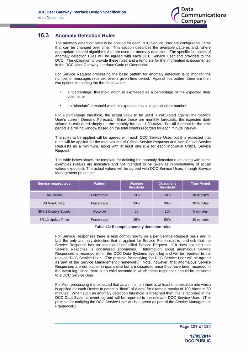
DCC User Gateway Interface Design Specification
Main Document
Page 127 of 134
12/09/2014 DCC PUBLIC
16.3 Anomaly Detection Rules
The anomaly detection rules to be applied for each DCC Service User are configurable items that can be changed over time. This section describes the available patterns and, where appropriate, related algorithms that are used for anomaly detection. The specific instances of anomaly detection rules will be agreed with each DCC Service User and provided to the DCC. The obligation to provide these rules and a template for the information is documented in the DCC User Gateway Interface Code of Connection.
For Service Request processing the basic pattern for anomaly detection is to monitor the number of messages received over a given time period. Against this pattern there are then two options for setting the threshold values:
• a “percentage” threshold which is expressed as a percentage of the expected daily volume; or
• an “absolute” threshold which is expressed as a single absolute number.
For a percentage threshold, the actual value to be used is calculated against the Service User’s current Demand Forecast. Since these are monthly forecasts, the expected daily volume is calculated simply as the monthly forecast / 30 days. For all thresholds, the time period is a rolling window based on the total counts recorded for each minute interval.
The rules to be applied will be agreed with each DCC Service User, but it is expected that rules will be applied for the total volume of Critical Service Requests and Non-Critical Service Requests as a minimum, along with at least one rule for each individual Critical Service Request.
The table below shows the template for defining the anomaly detection rules along with some examples (values are indicative and not intended to be taken as representative of actual values expected). The actual values will be agreed with DCC Service Users through Service Management processes.
Service request type Pattern Warning threshold
Quarantine threshold
Time Period
All Critical Percentage 10% 20% 30 minutes
All Non-Critical Percentage 20% 30% 30 minutes
SR7.2 Disable Supply Absolute 50 200 5 minutes
SR1.2 Update Price Percentage 25% 50% 30 minutes
Table 42: Example anomaly detection rules
For Service Responses there is less configurability on a per Service Request basis and in fact the only anomaly detection that is applied for Service Responses is to check that the Service Response has an associated unfulfilled Service Request. If it does not then that Service Response is considered anomalous. Information about anomalous Service Responses is recorded within the DCC Data Systems event log and will be reported to the relevant DCC Service User. (The process for notifying the DCC Service User will be agreed as part of the Service Management Framework.) Note, however, that anomalous Service Responses are not placed in quarantine but are discarded once they have been recorded in the event log, since there is no valid scenario in which these responses should be delivered to a DCC Service User.
For Alert processing it is expected that as a minimum there is at least one absolute rule which is applied for each Device to detect a “flood” of Alerts, for example receipt of 100 Alerts in 30 minutes. When such an anomaly detection threshold is breached then this is recorded in the DCC Data Systems event log and will be reported to the relevant DCC Service User. (The process for notifying the DCC Service User will be agreed as part of the Service Management Framework.)

DCC User Gateway Interface Design Specification
Main Document
Page 128 of 134
12/09/2014 DCC PUBLIC
Appendices
Appendix 1 – Glossary
Acronym Description
ACB Access Control Broker
ALCS Auxiliary Load Control Switch
API Application Programming Interface
BS British Standard
CA Certificate Authority
CAD Consumer Access Device
CCS Customer Consent Service
CESG Communications Electronic Security Group, the UK Government’s National Technical Authority for Information Assurance
CHECK UK government IT Health Check Service
CHTS Communications Hub Technical Specifications
CIN Customer Identification Number
CISO Chief Information Security Officer
CMS Customer Management Service
CoCo Code of Connection
CoS Change of Supplier
CoT Change of Tenancy
CR Credit (Meter Payment Mode)
CREST A not for profit organisation for the information security industry
CSP Communications Services Provider
CSR Certification Signing Request
CV Command Variant
DCC Data Communications Company
DCCKI Data Communications Company Key Infrastructure
DECC Department of Energy and Climate Change
DEMS Device Estate Management Service
Device ID Unique number by which an individual Device can be identified, as allocated to that Device in accordance with SMETS or CHTS (where applicable)
DMS Device Management Service
DSP Data Service Provider
DUGC DCC User Gateway Catalogue
DUGIDS DCC User Gateway Interface Design Specification (this document set)
DUGIS DCC User Gateway Interface Specification
DUGIS Format
Format defined in this document set, i.e. the XML format defined in the XSD (DUGIS XML Schema)

DCC User Gateway Interface Design Specification
Main Document
Page 129 of 134
12/09/2014 DCC PUBLIC
Acronym Description
ECB European Central Bank
ECDH Elliptic Curve Diffie Helman
ECDSA Elliptic Curve Digital Signature Algorithm
EES Electricity Export Supplier
EIS Electricity Import Supplier
ENO Electricity Network Operator
ENUM ENUMeration
FDEDA Future Dated Execution Device Alert
FS Firmware Service
GBCS Great Britain Companion Specification
GBCS UC Great Britain Companion Specification Use Case
GIS Gas Import Supplier
GMAC Galois Message Authentication Code
GNO Gas Network Operator
GPG CESG Good Practice Guide
HAN Home Area Network
HCALCS HAN Connected Auxiliary Load Control Switch
HHT Hand Held Terminal
HMG Her Majesty’s Government
HTTP HyperText Transport Protocol
HTTPS HyperText Transport Protocol Secure
ICT Information & Communications Technology
ID Identifier
IHD In Home Display
IP Internet Protocol
ISMS Information Security Management System
ISO International Organization for Standardization
IT Information Technology
KRP Known Remote Party (to a Device)
MAC Message Authentication Code
MPAN Meter Point Administration Number (Electricity)
MPRN Meter Point Reference Number (Gas)
M2M Machine To Machine
N/A Not Applicable
OU Other User
PEP Policy Enforcement Point
PKCS Public Key Cryptography Standards
PMS Product Management Service
PP PrePayment (Meter Payment Mode)

DCC User Gateway Interface Design Specification
Main Document
Page 130 of 134
12/09/2014 DCC PUBLIC
Acronym Description
PPMID PrePayment Interface Device
PS Prepay Service
PTUT Prepayment Top Up Token
RACI Response and Alert Common Interface
RNDS Record Network Data Service
RS Reading Service
SEC Smart Energy Code
SECCo Company established to facilitate the operation of the SEC
SLA Service Level Agreement
SMETS2 Smart Metering Equipment Technical Specifications second version
SMKI Smart Meter Key Infrastructure
SMS Smart Metering Systems
SMS Supply Management Service
SM WAN Smart Meter Wide Area Network
SNA Supplier Nominated Agent
SOAP Simple Object Access Protocol
SS Scheduling Service
SU Service User
TBC To Be Completed
TLS Transport Layer Security
TOU Time Of Use
UC Use Case
UKAS United Kingdom Accreditation Service
UPRN Unique Property Reference Number
URI Uniform Resource Identifier
URL Uniform Resource Locator
URP Unknown Remote Party (to a Device)
UTC Coordinated Universal Time
UTRN Unique Transaction Reference Number
VPLS Virtual Private LAN Service
VPN Virtual Private Network
WAN Wide Area Network
WIP Work In Progress
XML eXtensible Markup Language
XSD XML Schema Definition
Table 43 Definitions

DCC User Gateway Interface Design Specification
Main Document
Page 131 of 134
12/09/2014 DCC PUBLIC
Appendix 2 – DUGIS XML Schema Definition Instructions
The DUGIS XML schema can be viewed using Internet Explorer. The DUGIS XML schema contains 2 top level items that are used to define the messages passed between the DCC Service Users and the DCC Data Systems. These top level items are;
Request – Defines the Service Requests and Signed Pre-Command for the DCC Data
Systems
Response – Defines the data that is returned by the DCC Data Systems to the DCC
Service User. This covers Service Responses, Alerts and Acknowledgements.
The DUGIS XML schema definition uses a small number of constructs to define the structure and formats of the data.
The key constructs used in the schema are;
SimpleType – A basic data type for a data item for example an Integer or String.
SimpleTypes may have a restriction to only allow certain data items to be entered, for
example, EUI is defined as 8 pairs of hexadecimal strings separated by a colon.
Element – An item within the XML, this may be a standard data type or be defined by a
SimpleType.
ComplexType – A collection on Elements that make up a structure
Sequence – Within a ComplexType a Sequence specifies that the Elements must be
included in a particular order. Elements within the Sequence may be optional or
mandatory.
Choice – Within a ComplexType there may be a choice between which Elements are
allowable, this defined by a Choice.
The following is a simplified version of the section of the DUGIS XML schema that defines the Response;
<xs:complexType name="Response"> <xs:sequence> <xs:element name="Header"> <xs:complexType> <xs:sequence> <xs:element maxOccurs="1" name="RequestID" type="sr:RequestIDType" minOccurs="0"/> <xs:element maxOccurs="1" name="ResponseID" type="sr:ResponseIDType" minOccurs="0"/> <xs:element name="ResponseCode" type="sr:ResponseCode"/> <xs:element name="ResponseDateTime" type="xs:dateTime"/> </xs:sequence> </xs:complexType> </xs:element> <xs:element name="Body"> <xs:complexType> <xs:choice minOccurs="1"> <xs:element name="ResponseMessage" type="sr:ResponseMessage"> </xs:element> <xs:element name="DeviceAlertMessage" type="sr:DeviceAlertMessage"/> <xs:element name="DCCAlertMessage" type="sr:DCCAlertMessage"/> </xs:choice> </xs:complexType> </xs:element> <xs:element ref="ds:Signature" minOccurs="0"/> </xs:sequence> </xs:complexType>

DCC User Gateway Interface Design Specification
Main Document
Page 132 of 134
12/09/2014 DCC PUBLIC
The structure is defined as a ComplexType and identified by the name “Response”. It contains a Sequence of three Elements: Header, Body and ds:Signature. The four Elements of the Header have unique names, the first two are optional (minimum allowed occurrences is 0 and maximum is 1) and the last two are mandatory (minimum and maximum number of allowed occurrences is 1). The Body is a choice and so one of its three elements must be included in the XML. The ds:Signature is a reference to an external Schema and it is optional
The data types and restrictions are defined elsewhere in the schema, for example CommandVariant is defined as;
<xs:simpleType name="CommandVariant"> <xs:restriction base="xs:positiveInteger"> <xs:enumeration value=”1"/> <xs:enumeration value=”2"/> <xs:enumeration value=”3"/> <xs:enumeration value=”4"/> <xs:enumeration value=”5"/> <xs:enumeration value=”6"/> <xs:enumeration value=”7"/> <xs:enumeration value=”8"/> </xs:restriction> </xs:simpleType>
That is a positive integer that must be between the values 1 and 8 inclusive.
Note that the education site w3schools.com provides a useful primer on XML schemas with many examples, see http://www.w3schools.com/schema/default.asp

DCC User Gateway Interface Design Specification
Main Document
Page 133 of 134
12/09/2014 DCC PUBLIC
Appendix 3 – RACI XML Schema Definition Instructions
The RACI XML schema can be viewed using Internet Explorer. The RACI XML schema contains 1 top level item that is used to define the data passed from the Parse software to DCC Service User’s systems. This top level item is as follows;
GBCSResponse – Defines the data that is returned by the Parse software to the DCC
Service User. This covers Service Responses (from Device) and Device Alerts.
The RACI XML schema definition uses the same constructs as the DUGIS XML schema (see Appendix 2) to define the structure and formats of the data.
The GBCSResponse also follows a similar approach to that defined in the DUGIS XML schema, in that it is defined as a ComplexType and identified by the name “GBCSResponse”. It contains a Sequence of two Elements: Header and Body.
A more detailed set of information on the RACI XML schema is contained in Annex 18.

DCC User Gateway Interface Design Specification
Main Document
Page 134 of 134
12/09/2014 DCC PUBLIC
Revision History
Revision Date Summary of Changes Version
22/11/2013 Initial Draft for Internal Review 0.1
29/11/2013 Draft for Review 0.2
18/12/2013 Draft for Review 0.3
23/12/2013 Draft for Review 0.4
07/01/2014 Published for Service User consultation 0.5
28/02/2014 Consultation response. DCC assured product. 0.6
27/06/2014 Interim updates to support GBCS proving and DCC design activities.
DCC internal version.
0.7
12/09/2014 Updated to align to GBCS v0.8 0.8