dce33 service parts - scotsman; ice
TRANSCRIPT

DCE33 SERVICE PARTS
The section contains the parts list for the DCE33. The DCE33 has been manufactured in either a White,
Black or Stainless Steel finish.
A "D" series model was introduced in 2011 (as in DCE33A-1BD), it has a different timer and wiring
diagram.
Please check the part description before ordering any part.
Table of Contents
Cabinet ····································································································································· Page 2
Pump, Evaporator, Storage Bin ································································································ Page 3
Drain Pump Components ········································································································· Page 4
Condensing Unit ······················································································································· Page 5
Reservoir ·································································································································· Page 6
CONTROL BOX - all models except DCE33A-1BD, DCE33PA-1BD, DCE33A-1SSD or
DCE33PA-1SSD ······················································································································· Page 7
CONTROL BOX - for DCE33A-1BD, DCE33PA-1BD, DCE33A-1SSD or DCE33PA-1SSD ··· Page 8
Compressor ······························································································································ Page 9
Drain Pump Model Wiring Diagram - Prior to August 2000 ····················································· Page 11
Gravity Drain Model Wiring Diagram - Prior to August 2000 ··················································· Page 12
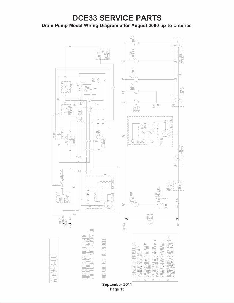
Drain Pump Model Wiring Diagram after August 2000 up to D series ···································· Page 13
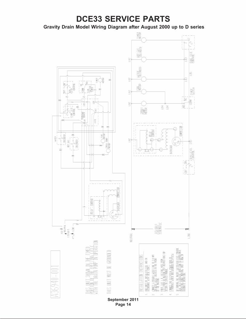
Gravity Drain Model Wiring Diagram after August 2000 up to D series ·································· Page 14
Wiring Diagram for DCE33A-1BD, DCE33PA-1BD, DCE33A-1SSD or DCE33PA-1SSD ······· Page 15
Schematic Diagram DCE33A-1BD, DCE33PA-1BD, DCE33A-1SSD or DCE33PA-1SSD ····· Page 16
DCE33 SERVICE PARTS
August 2014
Page 2
1,
includes items
2,3,4,5,6, & 7
2
9
17
2214
13
16
20
10
4
21
15
3,
includes 5
8
11
7
19
7
6
18
5
8a
8b
23
Item Part
Number Number Description
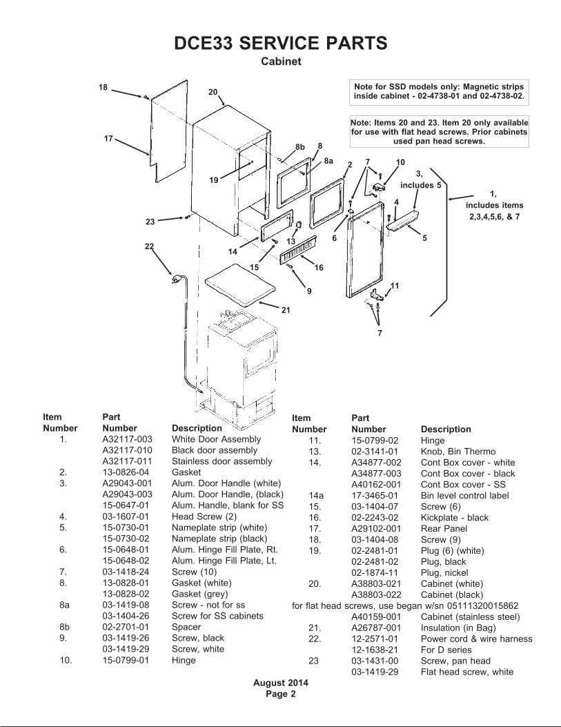
1. A32117-003 White Door Assembly
A32117-010 Black door assembly
A32117-011 Stainless door assembly
2. 13-0826-04 Gasket
3. A29043-001 Alum. Door Handle (white)
A29043-003 Alum. Door Handle, (black)
15-0647-01 Alum. Handle, blank for SS
4. 03-1607-01 Head Screw (2)
5. 15-0730-01 Nameplate strip (white)
15-0730-02 Nameplate strip (black)
6. 15-0648-01 Alum. Hinge Fill Plate, Rt.
15-0648-02 Alum. Hinge Fill Plate, Lt.
7. 03-1418-24 Screw (10)
8. 13-0828-01 Gasket (white)
13-0828-02 Gasket (grey)
8a 03-1419-08 Screw - not for ss
03-1404-26 Screw for SS cabinets
8b 02-2701-01 Spacer
9. 03-1419-26 Screw, black
03-1419-29 Screw, white
10. 15-0799-01 Hinge
Item Part
Number Number Description
11. 15-0799-02 Hinge
13. 02-3141-01 Knob, Bin Thermo
14. A34877-002 Cont Box cover - white
A34877-003 Cont Box cover - black
A40162-001 Cont Box cover - SS
14a 17-3465-01 Bin level control label
15. 03-1404-07 Screw (6)
16. 02-2243-02 Kickplate - black
17. A29102-001 Rear Panel
18. 03-1404-08 Screw (9)
19. 02-2481-01 Plug (6) (white)
02-2481-02 Plug, black
02-1874-11 Plug, nickel
20. A38803-021 Cabinet (white)
A38803-022 Cabinet (black)
for flat head screws, use began w/sn 05111320015862
A40159-001 Cabinet (stainless steel)
21. A26787-001 Insulation (in Bag)
22. 12-2571-01 Power cord & wire harness
12-1638-21 For D series
23 03-1431-00 Screw, pan head
03-1419-29 Flat head screw, white
Note: Items 20 and 23. Item 20 only availablefor use with flat head screws. Prior cabinets
used pan head screws.
Cabinet
Note for SSD models only: Magnetic stripsinside cabinet - 02-4738-01 and 02-4738-02.
DCE33 SERVICE PARTS
September 2011
Page 3
14
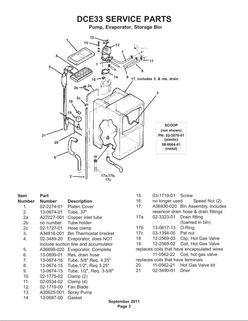
SCOOP
(not shown)
PN: 02-3070-01(plastic)
08-0664-01(metal)
4
51
8
15
16
12
7
9
11
6
13
1
17, includes 3, & res. drain
20
19
18
3
2
Pump, Evaporator, Storage Bin
21
17a,17b,17c
2b
2c
2a
Item Part
Number Number Description
1. 02-2274-01 Platen Cover
2. 13-0674-01 Tube, 37"
2a A27027-001 Copper inlet tube
2b no number Tube holder
2c 02-1727-01 Hose clamp
3. A34816-001 Bin Thermostat bracket
4. 02-3489-20 Evaporator, does NOT
include suction line and accumulator
5. A36699-020 Evaporator, Complete
6. 13-0899-01 Res. drain hose
7. 13-0674-16 Tube, 5/8" Req. 4.25"
8. 13-0674-15 Tube,1/2", Req 3.25"
9. 13-0674-15 Tube, 1/2", Req. 3-5/8"
10. 02-1775-02 Clamp (2)
11. 02-0534-02 Clamp (4)
12. 02-1719-00 Fan Blade
13. A30625-001 Spray Pump
14. 13-0687-00 Gasket
15. 03-1719-01 Screw
16. no longer used Speed Nut (2)
17. A36930-020 Bin Assembly, includes
reservoir drain hose & drain fittings
17a 02-3323-01 Drain fitting
(foamed in bin)
17b 13-0617-13 O-Ring
17c 03-1394-05 Pal nut
18 12-2569-03 Clip, Hot Gas Valve
19. 12-2569-02 Coil, Hot Gas Valve
replaces coils that have encapsulated wires
11-0562-22 Coil, hot gas valve
replaces coils that have terminals
20. 11-0562-21 Hot Gas Valve kit
21 02-3490-01 Drier

DCE33 SERVICE PARTS
April 2013
Page 4
Drain Pump Components
3
1
2
7
6
10
4
5
9
13
12
11
Item Part
Number Number Description
1. A36892-020 Drain Pump Kit, for all except DCE33A-1BD and DCE33A-1SSD
A39885-001 Drain pump kit, for DCE33A-1BD or DCE33A-1SSD
use to convert any DCE33 gravity model to pump type. Pump must be ordered separately.
2 12-2503-21 Drain pump only,
use to replace drain pumps or w/kit to convert.
Pump Kit Service Parts
3 02-3369-01 Inlet hose
4 02-3522-01 Elbow
5 02-3374-01 Check valve
6 13-0617-08 O-ring
7 11-0504-01 Pressure switch
8 obsolete Impeller & housing kit
9 A37334-001 Discharge hose
10 05-0591-01 Switch hose
11 A36746-001 Mounting bracket
12 02-3406-01 Barbed connector
13 02-2814-11 Clamp
14 12-2580-01 Harness
12-3001-01 Harness, for converted-to-pump DCE33A-1BD, DCE33PA-1D, DCE33A-1SSD
or DCE33PA-1SSD
15 03-3904-01 Check valve spring
15

DCE33 SERVICE PARTS
April 2013
Page 5
Item Part
Number Number Description
1. 03-1404-08 Screw (4)
2. 18-3710-01 Fan Blade
3. A28798-001 Fan Motor Bracket
4. 12-2396-21 Fan Motor
18-8752-10 Blade pad
18-8752-11 Blade nut
5. 02-2871-01 Fan Shroud
6. 18-3729-01 Condenser
7. 18-4700-28 Grommet
8. 03-1608-01 Leg Leveler
9. 03-1407-08 Washer
03-3821-01 Clip
10. A29015-001 Bracket
Item Part
Number Number Description
11 12-1213-10 Bushing
12 A37732-001 Upper base plate
13 13-0609-00 Foam tape
14 A28921-001 Lower base plate
A38638-001 Lower base plate
use began w/sn 05111320015862
Support brackets part of item 12
A40164-001 Base pan for -1SSD
15 03-1531-01 Screw
7
4
9
8
5
6
2
10
3
1
1
12
13
14
15
Condensing Unit
Support Bracket
11
DCE33 SERVICE PARTS
September 2011
Page 6
Item Part
Number Number Description
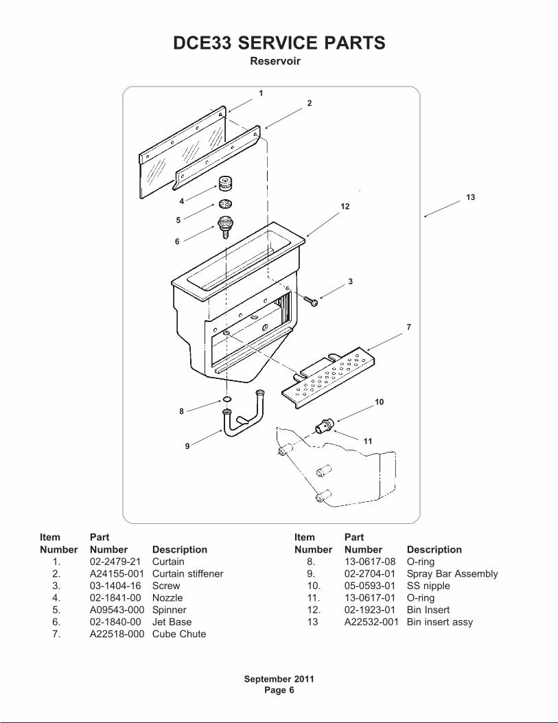
1. 02-2479-21 Curtain
2. A24155-001 Curtain stiffener
3. 03-1404-16 Screw
4. 02-1841-00 Nozzle
5. A09543-000 Spinner
6. 02-1840-00 Jet Base
7. A22518-000 Cube Chute
Item Part
Number Number Description
8. 13-0617-08 O-ring
9. 02-2704-01 Spray Bar Assembly
10. 05-0593-01 SS nipple
11. 13-0617-01 O-ring
12. 02-1923-01 Bin Insert
13 A22532-001 Bin insert assy
3
1
2
124
5
6
8
9
10
11
7
13
Reservoir

DCE33 SERVICE PARTS
April 2014
Page 7
4
6
8
7
3
1
2
8
9
11
10
12
Blue Valve Shown
Item Part
Number Number Description
1. A25981-001 Terminal Board
2. 03-1638-01 Screw
3. 12-1980-21 Timer And Switch
4. 11-0619-21 Cube Size Control
5. 11-0616-21 Bin Level Control, incl 5a
5a 02-4817-01 Knob for item 5 -
Danfoss only
6. 12-2907-21 Inlet Water Valve Kit
(includes new fittings)
12-2907-31 Coil only for brass valve
12-2410-31 Coil only for plastic valve
Item Part
Number Number Description
7. 12-1213-12 Bushing
8. 03-1403-17 Screw
9 12-1213-04 Snap bushing
10 03-1638-02 Screw
11 02-2242-06 Stand off
12 02-2242-05 Stand off
Not Shown
13 A39918-001 Kit to retrofit electronic
timer to prior model.
CONTROL BOX - all models except DCE33A-1BD, DCE33PA-1BD, DCE33A-1SSD orDCE33PA-1SSD
Brass Inlet Water Valve Mounts toControl Box As Shown
5

DCE33 SERVICE PARTS
April 2014
Page 8
CONTROL BOX - for DCE33A-1BD, DCE33PA-1BD, DCE33A-1SSD or DCE33PA-1SSD
Item Part
Number Number Description
1 11-0619-21 Cube size control
2 11-0616-21 Bin level control, includes 2a
2a 02-4817-01 Knob, for Danfoss thermostat only
3 12-2985-01 Timer
03-1419-16 Screw
4 12-1213-12 Snap bushing
5 12-2907-21 Inlet water valve kit, includes new fittings
12-2907-31 Coil only for inlet water valve
6 12-1213-04 Snap bushing
2
1
3
5
6
4

DCE33 SERVICE PARTS
September 2011
Page 9
Item Part
Number Number Description
1. 18-8776-21 Compressor Kit, Includes Relay, Overload, Instructions
2. 18-8776-51 Relay
3 18-8776-52 Overload
4. 18-8776-54 Cover
Compressor
12
3
4

DCE33 SERVICE PARTS
September 2011
Page 10
Kit PartsK-SS Door Sleeve Kit
02-3846-01 Sleeve
02-3847-01 Handle
03-1403-50 Screw for handle
03-1407-06 Washer
03-1410-03 Lockwasher
03-3811-01 Screw
DCE33 SERVICE PARTS
September 2011
Page 11
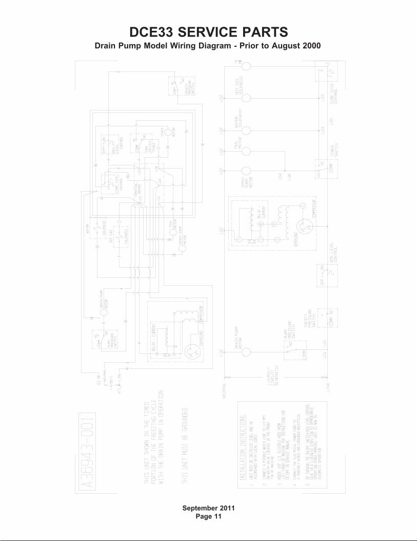
Drain Pump Model Wiring Diagram - Prior to August 2000

DCE33 SERVICE PARTS
September 2011
Page 12
Gravity Drain Model Wiring Diagram - Prior to August 2000
DCE33 SERVICE PARTS
September 2011
Page 13
Drain Pump Model Wiring Diagram after August 2000 up to D series
DCE33 SERVICE PARTS
September 2011
Page 14
Gravity Drain Model Wiring Diagram after August 2000 up to D series
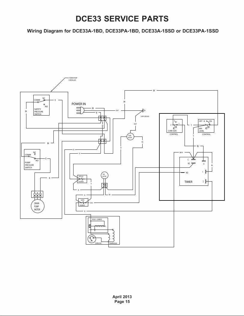
Wiring Diagram for DCE33A-1BD, DCE33PA-1BD, DCE33A-1SSD or DCE33PA-1SSD
DCE33 SERVICE PARTS
April 2013
Page 15
BU
Y
TIMER
BK
BK
W
BK/W
BK
2
1
6
C
NC
NO
COMPRESSOR
RELAY - CURRENT
OVERLOAD
1
MS
3
1
Y21
3
CONTROL
CUBE SIZE
W
DRAINPUMPMOTOR
W
BK
R
BK
PUMPPRESSURESWITCH
NO
COMMNC
R
SAFETYPRESSURESWITCH
NO
COMMNC
W
PUMPMOTOR
BU
W
W
R/W
WATER
SOLENOID
FANMOTOR
R
HOT GAS
SOLENOID
BN
GN/Y
EARTH GROUND
ONOFF
BINLEVEL
CONTROL
POWER IN
W
BKGN/Y
W
W
IF DRAIN PUMPIS INSTALLED
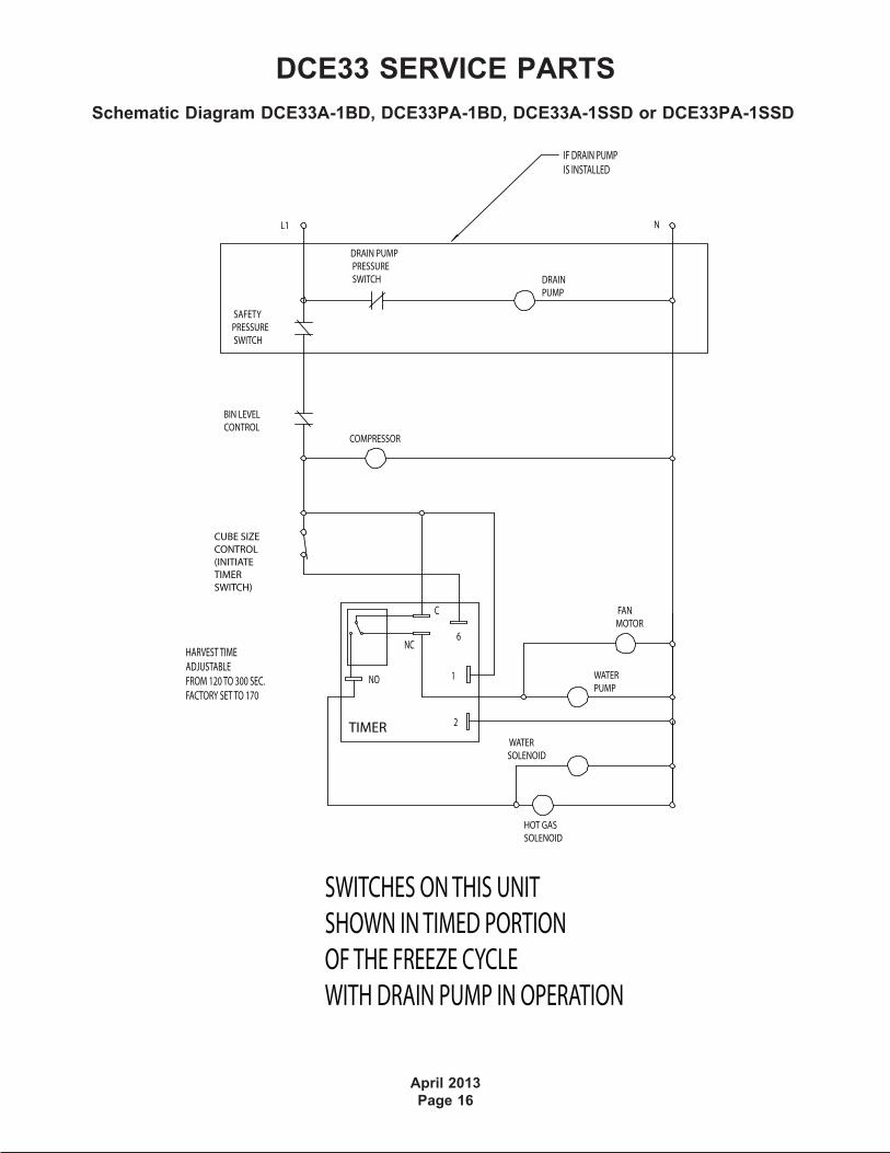
Schematic Diagram DCE33A-1BD, DCE33PA-1BD, DCE33A-1SSD or DCE33PA-1SSD
DCE33 SERVICE PARTS
April 2013
Page 16
HARVEST TIMEADJUSTABLE FROM 120 TO 300 SEC.FACTORY SET TO 170
TIMER 2
1
6
C
NC
NO
CUBE SIZECONTROL(INITIATETIMERSWITCH)
COMPRESSOR
SWITCHES ON THIS UNITSHOWN IN TIMED PORTIONOF THE FREEZE CYCLEWITH DRAIN PUMP IN OPERATION
BIN LEVELCONTROL
SAFETYPRESSURE SWITCH
DRAIN PUMP PRESSURE SWITCH DRAIN
PUMP
HOT GASSOLENOID
FANMOTOR
L1 N
WATERPUMP
WATERSOLENOID
IF DRAIN PUMPIS INSTALLED