dcgen
TRANSCRIPT
8/7/2019 dcgen
http://slidepdf.com/reader/full/dcgen 1/17
DC generator theory
This worksheet and all related files are licensed under the Creative Commons Attribution License,version 1.0. To view a copy of this license, visit http://creativecommons.org/licenses/by/1.0/, or send aletter to Creative Commons, 559 Nathan Abbott Way, Stanford, California 94305, USA. The terms andconditions of this license allow for free copying, distribution, and/or modification of all licensed works bythe general public.
Resources and methods for learning about these subjects (list a few here, in preparation for yourresearch):
1
8/7/2019 dcgen
http://slidepdf.com/reader/full/dcgen 2/17
Questions
Question 1
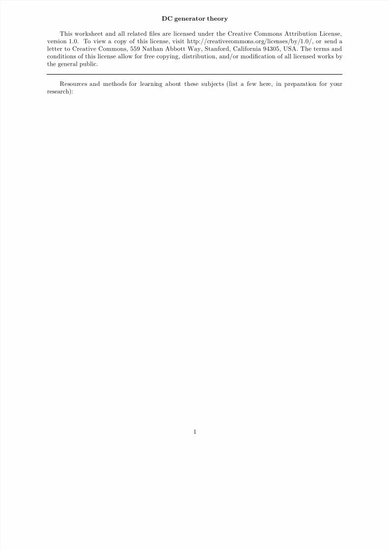
If an electric current is passed through this wire, which direction will the wire be pushed (by theinteraction of the magnetic fields)?
MagnetN S MagnetN S
+-
wire
Is this an example of an electric motor or an electric generator ?file 00382
2

8/7/2019 dcgen
http://slidepdf.com/reader/full/dcgen 3/17
Question 2
If this wire (between the magnet poles) is moved in an upward direction, what polarity of voltage willthe meter indicate?
MagnetN S MagnetN Swire
V Ω
COMA
motion
Describe the factors influencing the magnitude of the voltage induced by motion, and determine whetherthis is an example of an electric motor or an electric generator .
file 00806
3

8/7/2019 dcgen
http://slidepdf.com/reader/full/dcgen 4/17
Question 3
If this wire (between the magnet poles) is moved in an upward direction, and the wire ends are connectedto a resistive load, which way will current go through the wire?
MagnetN S MagnetN Swire
motion
We know that current moving through a wire will create a magnetic field, and that this magnetic field willproduce a reaction force against the static magnetic fields coming from the two permanent magnets. Whichdirection will this reaction force push the current-carrying wire? How does the direction of this force relateto the direction of the wire’s motion? Does this phenomenon relate to any principle of electromagnetismyou’ve learned so far?
file 00807
4
8/7/2019 dcgen
http://slidepdf.com/reader/full/dcgen 5/17
Question 4
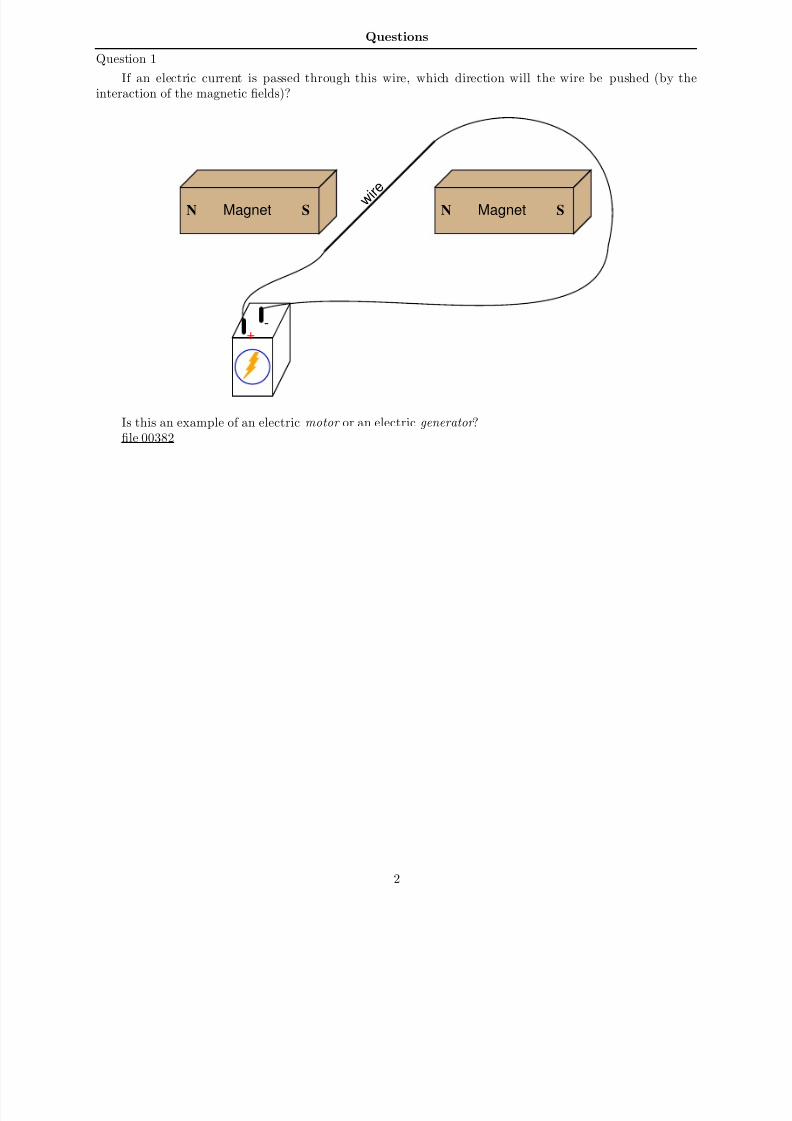
Determine the polarity of induced voltage between the ends of this wire loop, as it is rotated betweenthe two magnets:
MagnetN S MagnetN S
MagnetN S MagnetN S
MagnetN S MagnetN S
sequence over time
MagnetN S MagnetN S
MagnetN S MagnetN S
file 00808
5

8/7/2019 dcgen
http://slidepdf.com/reader/full/dcgen 6/17
Question 5
If the ends of a wire loop are attached to two half-circular metal strips, arranged so that the two stripsalmost form a complete circle, and those strips are contacted by two ”brushes” which connect to oppositepoles of a battery, what polarity of voltage will be measured as the loop is rotated counter-clockwise?
MagnetN S MagnetN S
? ?
file 00809
Question 6
With regard to a DC electric generator, what is the neutral plane? Why is this important?file 00813
Question 7How does Faraday’s Law of electromagnetic induction relate to the voltage output of a DC generator?
According to Faraday’s Law, what factors can we alter to increase the voltage output by a DC generator?file 00810
Question 8
Suppose a generator is mechanically coupled to an internal combustion engine in an automobile, for thepurpose of charging the starting battery. In order that the battery not be over-charged by the generator,there must be some way of controlling the generator’s output voltage over a wide range of engine speeds.
How is this regulation of generator output voltage typically achieved? What variable within the generatormay be most easily adjusted to maintain a nearly constant output voltage? Express your answer in relationto Faraday’s Law of electromagnetic induction.
file 00811
6

8/7/2019 dcgen
http://slidepdf.com/reader/full/dcgen 7/17
Question 9
DC generators will act as DC motors if connected to a DC power source and not spun at a sufficientspeed. This is a problem in DC power systems, as the generator will act as a load, drawing energy fromthe battery, when the engine or other ”prime mover” device stops moving. This simple generator/batterycircuit, for example, would not be practical for this reason:
Gen BatteryGenerator
Back in the days when automobiles used DC generators to charge their batteries, a special relay calledthe reverse current cutout relay was necessary to prevent battery discharge through the generator wheneverthe engine was shut off:
Gen BatteryGenerator
Reverse currentcutout relay
series coil
shunt coil
When the generator is spun fast enough, it generates enough voltage to energize the shunt coil withenough current to close the relay contact. This connects the generator with the battery, and charging currentflows through the series coil, creating even more magnetic attraction to hold the relay contact closed. If thebattery reaches a full charge and does not draw any more charging current from the generator, the relay willstill remain closed because the shunt coil is still energized.
However, the relay contact will open if the generator ever begins to act as a load to the battery, drawingany current from it. Explain why this happens.
file 00804
7

8/7/2019 dcgen
http://slidepdf.com/reader/full/dcgen 8/17
Question 10
A shunt-wound generator has an electromagnet ”field” winding providing the stationary magnetic fieldin which the armature rotates:
Field Armature
A
To DC
Ammeter
Circuitbreaker
load
Generator
Like all electromagnets, the magnetic field strength produced is in direct proportion to the amountof current through the wire coil. But when the generator is sitting still, its output voltage is zero, andtherefore there will be no current through the field winding to energize it and produce a magnetic field forthe armature to rotate through. This causes a problem, since the armature will not have any voltage inducedin its windings until it is rotating and it has a stationary magnetic field from the field winding to rotate
through.It seems like we have a catch-22 situation here: the generator cannot output a voltage until its field
winding is energized, but its field winding will not be energized until the generator (armature) outputs somevoltage. How can this generator ever begin to output voltage, given this predicament?
file 00812
Question 11
In a shunt-wound DC generator, the output voltage is determined by the rotational speed of the armatureand the density of the stationary magnetic field flux. For a given armature speed, what prevents the outputvoltage from ”running away” to infinite levels, since the output voltage energizes the field winding, whichleads to greater field flux, which leads to greater output voltage, which leads to greater field flux, which leadsto . . . ?
Field Armature
A
To DC
Ammeter
Circuitbreaker
load
Generator
Obviously, there must be some inherent limit to this otherwise vicious cycle. Otherwise, the outputvoltage of a shunt-wound DC generator would be completely unstable.
file 00814
8
8/7/2019 dcgen
http://slidepdf.com/reader/full/dcgen 9/17
Question 12
In most high-power DC generator and motor designs, the wire used to make the field winding is muchthinner gauge than the wire used to make the armature winding. This indicates the relative magnitude of current through these respective windings, with the armature coils conducting much more current than thefield coils.
That the armature conducts more current than the field is no small matter, because all current throughthe armature must be conducted through the brushes and commutator bars. The more current thesecomponents have to carry, the shorter their life, all other factors being equal.
Couldn’t the generator be re-designed so that the field conducted most of the current, with the armature
only conducting a small amount? This way, the brushes and commutator bars would only have to carry afraction of their normal current, making them less expensive and longer-lived. Explain why this is impossibleto do.
Hint: consider the design of a permanent-magnet generator.file 00815
Question 13
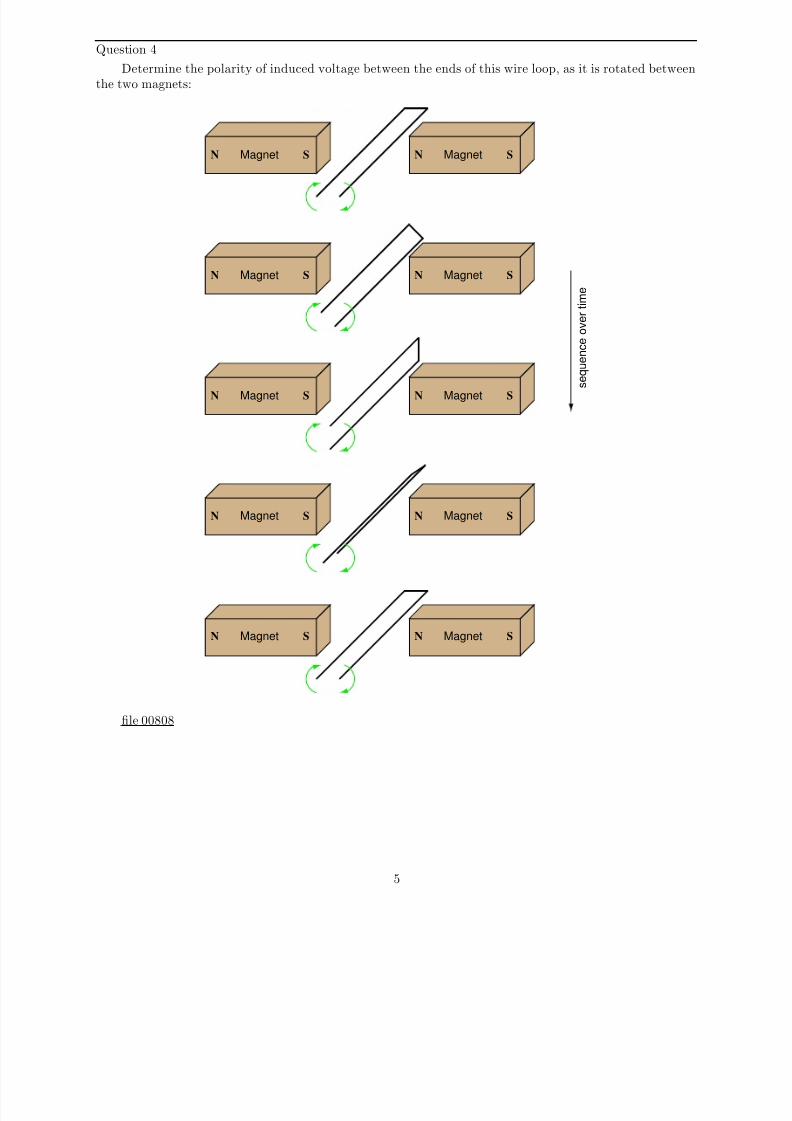
Generators used in battery-charging systems must be regulated so as to not overcharge the battery(ies)they are connected to. Here is a crude, relay-based voltage regulator for a DC generator:
Field Armature
Generator
Battery
Regulatingrelay
Simple electromechanical relay circuits such as this one were very common in automotive electricalsystems during the 1950’s, 1960’s, and 1970’s. The fundamental principle upon which their operation isbased is called negative feedback : where a system takes action to oppose any change in a certain variable.In this case, the variable is generator output voltage. Explain how the relay works to prevent the generatorfrom overcharging the battery with excessive voltage.
file 01021
9
8/7/2019 dcgen
http://slidepdf.com/reader/full/dcgen 10/17
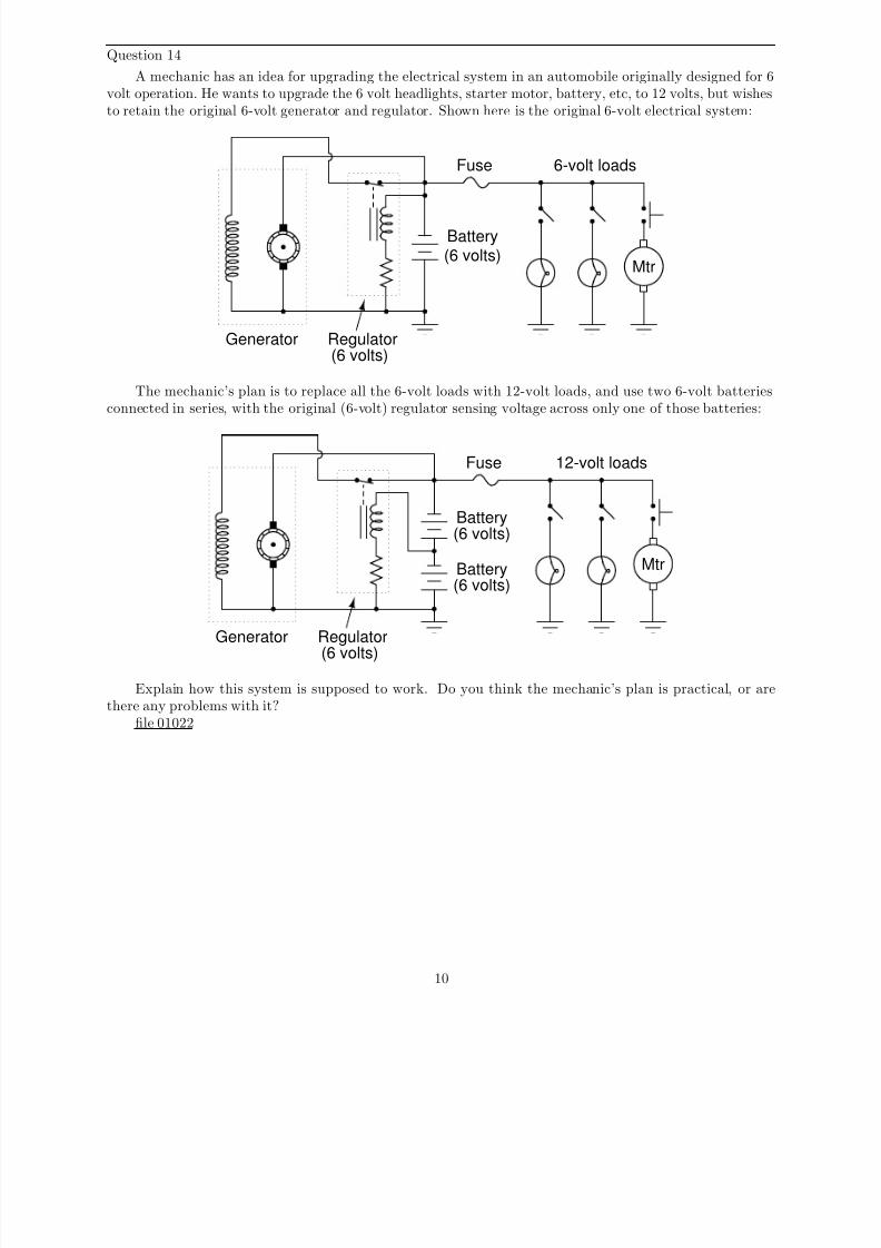
Question 14
A mechanic has an idea for upgrading the electrical system in an automobile originally designed for 6volt operation. He wants to upgrade the 6 volt headlights, starter motor, battery, etc, to 12 volts, but wishesto retain the original 6-volt generator and regulator. Shown here is the original 6-volt electrical system:
Generator
Battery(6 volts)
Regulator(6 volts)
Mtr
6-volt loadsFuse
The mechanic’s plan is to replace all the 6-volt loads with 12-volt loads, and use two 6-volt batteriesconnected in series, with the original (6-volt) regulator sensing voltage across only one of those batteries:
Generator
Battery
Regulator
(6 volts)
Mtr
12-volt loads
(6 volts)
Battery(6 volts)
Fuse
Explain how this system is supposed to work. Do you think the mechanic’s plan is practical, or arethere any problems with it?
file 01022
10
8/7/2019 dcgen
http://slidepdf.com/reader/full/dcgen 11/17
Answers
Answer 1
The wire will be pushed up in this motor example.
Answer 2
The voltmeter will indicate a negative voltage in this generator example.
Answer 3
The reaction force will be directly opposed to the direction of motion, as described by Lenz’s Law.
Follow-up question: What does this phenomenon indicate to us about the ease of moving a generatormechanism under load, versus unloaded? What effect does placing an electrical load on the output terminalsof a generator have on the mechanical effort needed to turn the generator?
11
8/7/2019 dcgen
http://slidepdf.com/reader/full/dcgen 12/17
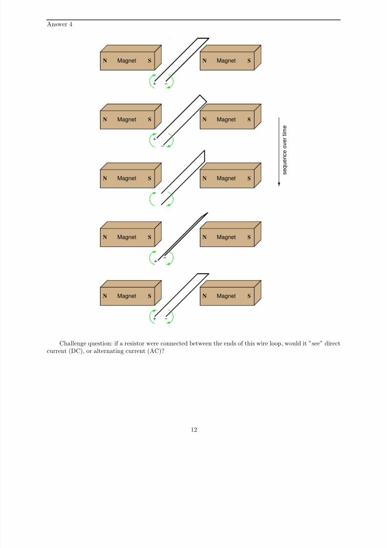
Answer 4
MagnetN S MagnetN S
MagnetN S MagnetN S
MagnetN S MagnetN S
sequence over time
MagnetN S MagnetN S
MagnetN S MagnetN S
Challenge question: if a resistor were connected between the ends of this wire loop, would it ”see” directcurrent (DC), or alternating current (AC)?
12

8/7/2019 dcgen
http://slidepdf.com/reader/full/dcgen 13/17
Answer 5
MagnetN S MagnetN S
Follow-up question: does the polarity measured at the two carbon brushes ever reverse? Or, to phrasethe question another way, if a resistor were connected between the two brush contacts, would it ”see” directcurrent (DC) or alternating current (AC)? Explain your answer.
Answer 6
The ”neutral plane” is that point of rotation where a rotating armature winding has no induced voltagein it, due to dφ
dtbeing equal to zero. In a simple, two-pole machine, the neutral plane is perpendicular to the
centerline of the field poles:
N S
Neutral plane
Answer 7
Increase the dφdt
rate of change, or increase the number of turns in the armature winding.
Answer 8
The most common method of generator voltage control is adjustment of field winding excitation.
Answer 9If a reverse current goes through the series coil, the magnetic field produced will ”buck” the magnetic
field produced by the shunt coil, thus weakening the total magnetic field strength pulling at the armature of the relay.
13
8/7/2019 dcgen
http://slidepdf.com/reader/full/dcgen 14/17
Answer 10
Usually, there is enough residual magnetism left in the field poles to initiate some generator action whenturned.
Challenge question: what we could do if the generator’s field poles ever totally lost their residualmagnetism? How could the generator ever be started?
Answer 11
At a certain amount of field winding current, the generator’s field poles saturate, preventing further
increases in magnetic flux.
Answer 12
It is impossible for the field winding to conduct more current than the armature in a functioning DCgenerator, because the armature has to be the source of electrical power, while the field is only a load .
Answer 13
If the battery voltage becomes excessive, the relay opens and de-energizes the field winding. When thevoltages sags back down to an acceptable level, the relay re-closes and re-energizes the field winding so thatthe generator can begin generating voltage again.
Challenge question: what would we have to change in this circuit to alter the generator’s voltageregulation set-point (the ”target” voltage at which the generator’s output is supposed to be regulated)?
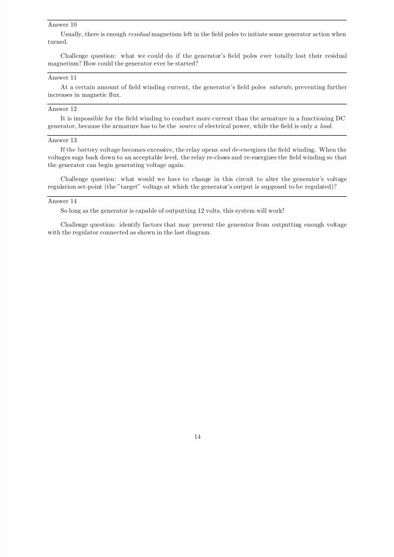
Answer 14
So long as the generator is capable of outputting 12 volts, this system will work!
Challenge question: identify factors that may prevent the generator from outputting enough voltagewith the regulator connected as shown in the last diagram.
14
8/7/2019 dcgen
http://slidepdf.com/reader/full/dcgen 15/17
Notes
Notes 1
A visual aid to understanding the interaction of the two magnetic fields is a diagram showing the linesof flux emanating from the permanent magnets, against the circular lines of flux around the wire. Ask thosestudents who came across similar illustrations in their research to draw a picture of this on the board infront of the class, for those who have not seen it.
Notes 2
Ask your students to explain their answers regarding factors that influence voltage magnitude. Wheredid they obtain their information? Are there any mathematical formulae relating these factors to induced
voltage?
Notes 3
If you happen to have a large, permanent magnet DC motor available in your classroom, you mayeasily demonstrate this principle for your students. Just have them spin the shaft of the motor (generator)with their hands, with the power terminals open versus shorted together. Your students will notice a hugedifference in the ease of turning between these two states.
After your students have had the opportunity to discuss this phenomenon and/or experience itthemselves, ask them why electromechanical meter movement manufacturers usually ship meters with ashorting wire connecting the two meter terminals together. In what way does a PMMC meter movementresemble an electric generator? How does shorting the terminals together help to protect against damagefrom physical vibration during shipping?
Ask your students to describe what factors influence the magnitude of this reaction force.Notes 4
Note that the two wire ends switch polarity as the loop rotates. Ask your students to explain why thepolarities are as they are.
Notes 5
Ask your students what the two half-circle metal strips are called, in electric motor/generatorterminology.
Notes 6
Ask your students why the ”neutral plane” is an important aspect of a DC generator or motor’s geometry.What relation does the neutral plane have with regard to brush positioning? At what point in the armature’s
rotation do we want to have the brushes break contact with one commutator bar and make contact withanother: when the coil primary to that commutator segment is outputting maximum voltage, or minimumvoltage?
Notes 7
Ask your students to write the equation for Faraday’s Law on the whiteboard, and then analyze it in aqualitative sense (with variables increasing or decreasing in value) to validate the answers.
The first answer to this question (increase dφdt
) has been left purposefully vague, in order to makestudents think. What, specifically, must be changed in order to increase this rate-of-change over time?Which real-world variables are changeable after the generator has been manufactured, and which are not?
Notes 8
Although adjustable field winding excitation is the most popular form of generator output voltagecontrol, it is not the only means. Challenge your students with inventing other means of charge control forthe battery in this automotive electrical system, besides field winding excitation control. What else can wedo to the generator, or to the circuit it is within, to achieve charge control for the battery?
15
8/7/2019 dcgen
http://slidepdf.com/reader/full/dcgen 16/17
Notes 9
A ”reverse current cutout” relay ingeniously exploits reversible magnetic polarities to close or opena contact under the proper conditions. Although DC generators are no longer used in the majorityof automobile electrical systems (AC alternators using bridge rectifiers to convert AC to DC are usedinstead, with the rectifier circuit naturally preventing reverse current), this application provides an excellentopportunity to explore an application of relay technology in the context of generator control.
Notes 10
Back in the days when generators were common in automotive electrical systems, this used to be a fairly
common problem. However, generators could be ”flashed” so as to re-establish this residual magnetic fieldonce again.
Notes 11
This question provides a great opportunity to review the concept of magnetic ”saturation,” as well asintroduce the engineering concept of positive feedback .
Notes 12
Being that brush and commutator wear is the main reason AC motors and generators are favored overDC, any idea that may potentially reduce the ”wear and tear” on DC motor or generator brushes is worthconsidering. However, the idea proposed in this question will never work. This is not necessarily an easyquestion to answer, as it tests the students’ comprehension of generator theory. The hint given in thequestion (”consider a permanent-magnet generator”) is intended to force students to simplify the problem,
by considering a working generator design that only has one winding (the armature). By simplifying theproblem in this way, students should see that the armature winding has to carry the bulk of the current ina DC generator.
Notes 13
The circuit drawn here is very similar to real generator regulator circuits used in American automobilesbefore the advent of inexpensive, reliable semiconductor circuits. I show it here not just for historicalbackground, but also to demonstrate how relatively crude circuits are still able to perform certain tasksreasonably well.
”Negative feedback” is one of the fundamental principles of electronics and electrical engineering. Asimple system like this provides a good way to gently introduce students to this vital concept.
16

8/7/2019 dcgen
http://slidepdf.com/reader/full/dcgen 17/17
Notes 14
In this question, we see a foreshadowing of op-amp theory, with the regulator’s negative feedback appliedto what is essentially a voltage divider (two equal-voltage batteries being charged by the generator). Theregulator circuit senses only 6 volts, but the generator outputs 12 volts.
Fundamentally, the focus of this question is negative feedback and one of its many practical applicationsin electrical engineering. The depth to which you discuss this concept will vary according to the students’readiness, but it is something you should at least mention during discussion on this question.
This idea actually came from one of the readers of my textbook series Lessons In Electric Circuits. Hewas trying to upgrade a vehicle from 12 volts to 24 volts, but the principle is the same. An important
difference in his plan was that he was still planning on having some 12-volt loads in the vehicle (dashboardgauges, starter solenoid, etc.), with the full 24 volts supplying only the high-power loads (such as the startermotor itself):
Generator
Battery
Regulator
MtrBattery
(12 volts)
(12 volts)
(12 volts)
24-volt loads
12-volt load
Fuse
As a challenge for your students, ask them how well they think this system would work. It is a bit morecomplex than the system shown in the question, due to the two different load banks.
17