dcm eliot cntrl copy 4 asme qms manual rev. 4.0 2018
TRANSCRIPT
SECTION: 1.1 - TITLE PAGE REVISION DATE: 2014-11-30
REVISION NUMBER: 4.0 PAGE: 1 of 1
DCM-MA-AQ-02-A
– This electronic document resides on DCM’s internal Intranet and shall be considered “Uncontrolled” if printed. –
-Confidential - Property of DCM – Do not duplicate, register or distribute in whole or in part, without first obtaining the written consent of the DCM Corporate Quality Manager
QUALITY MANUAL
For
CONSTRUCTION, REPAIR AND ALTERATION OF PRESSURE PIPING ASME B31.1 POWER PIPING INCLUDING BOILER EXTERNAL PIPING (BEP)
AND ASME B31.3 PROCESS PIPING
REPAIR AND ALTERATION OF SECTION I POWER BOILERS, SECTION IV HEATING BOILERS AND SECTION VIII DIVISON 1 PRESSURE VESSELS
PERFORMANCE QUALIFICATION TESTING OF PRESSURE WELDERS AND MACHINE WELDING OPERATORS EMPLOYED BY DCM INTEGRATED SOLUTIONS INC.
IN ACCORDANCE WITH ASME SECTION IX AND
APPLICABLE CODE(S) OF CONSTRUCTION, ABSA DOCUMENTS AB-518, AB-513, AND
THE ALBERTA SAFETY CODES ACT AND REGULATIONS
by
DCM Integrated Solutions Inc.
AT FIELD SITES IN ALBERTA CONTROLLED FROM
#184, 2693 Broadmoor Blvd. Sherwood Park, Alberta
T8H 0G1
MANUAL REVISION NO.: 4.0 DATE EFFECTIVE: 2015-01-30 REGISTRATION NUMBER: AQP-21453 MANUAL NUMBER: 04 HOLDER: Eliot (Company Server) CONTROLLED: UNCONTROLLED:

SECTION: 1.3 - ACRONYMS & DEFFINITIONS REVISION DATE: 2014-11-30
REVISION NUMBER: 4.0 PAGE: 1 of 5
DCM-MA-AQ-02-A
– This electronic document resides on DCM’s internal Intranet and shall be considered “Uncontrolled” if printed. –
-Confidential - Property of DCM – Do not duplicate, register or distribute in whole or in part, without first obtaining the written consent of the DCM Corporate Quality Manager
ACRONYMS:
AA: ADMINISTRATIVE ASSISTANT ABSA: ALBERTA BOILER SAFETY ASSOCIATION AIA: AUTHORIZED INSPECTION AGENCY AI: AUTHORIZED INSPECTOR ANSI: AMERICAN NATIONAL STANDARDS INSTITUTE ASNT AMERICAN SOCIETY FOR NONDESTRUCTIVE TESTING ASME: AMERICAN SOCIETY OF MECHANICAL ENGINEERS CE: CHIEF ESTIMATOR CGSB: CANADIAN GENERAL STANDARDS BOARD CSA: CANADIAN STANDARDS ASSOCIATION DE: DESIGN ENGINEER FIWP FIELD INSTALLATION WORK PACKAGE HP: HOLD POINT MDR MANUFACTURER’S DATA REPORT NDE: NON-DESTRUCTIVE EXAMINATION OEM ORIGINAL EQUIPMENT MANUFACTURER PD: PURCHASING DEPARTMENT PIR: PIPING INSPECTION REPORT PM: PROJECT MANAGER PRN ALBERTA PIPING REGISTRATION NUMBER PQR: PROCEDURE QUALIFICATION RECORD QA: QUALITY ASSURANCE CQM: CORPORATE QUALITY MANAGER QCM QUALITY CONTROL MANAGER QCS: QUALITY CONTROL SUPERVISOR SRS: SHIPPING/RECEIVING SUPERVISOR SS: SITE SUPERVISOR TT: THERMAL TREATMENT WPS: WELDING PROCEDURE SPECIFICATIONS WQ: WELDERS QUALIFICATION WQR: WELDER QUALIFICATION RECORD WOQR: WELDING OPERATOR QUALIFICATION RECORD

SECTION: 1.3 - ACRONYMS & DEFFINITIONS REVISION DATE: 2014-11-30
REVISION NUMBER: 4.0 PAGE: 2 of 5
DCM-MA-AQ-02-A
– This electronic document resides on DCM’s internal Intranet and shall be considered “Uncontrolled” if printed. –
-Confidential - Property of DCM – Do not duplicate, register or distribute in whole or in part, without first obtaining the written consent of the DCM Corporate Quality Manager
DEFINITIONS: ABSA
The regulatory organization delegated by the Province of Alberta to provide pressure equipment safety services under the Alberta Safety Codes Act, and act as the sole Jurisdiction/Regulatory Authority as defined in CSA B-51 Code and is accredited by the American Society of Mechanical Engineers (ASME).
ABSA AUTHORIZED INSPECTOR (AI) / SAFETY CODES OFFICER (SCO) A person appointed as a Safety Codes Officer for the purpose of administering the Alberta Safety Codes Act and Regulations (Pressure Equipment).
Alberta Safety Codes Act The Alberta Safety Codes Act; Statutes of Alberta, Chapter S-0.5 as it applies for pressure equipment and the following adopted regulations under the Safety Codes Act:
i. Pressure Welders Regulations ii. Administrative Items Regulation iii. Pressure Equipment Safety Regulations iv. Pressure Equipment Exemption Order
Alteration Any change in the item described on the original Manufacturer’s Data Report or Construction Data Report for Piping Systems that requires a change of design calculations or otherwise affects the pressure containing capability of the boiler, pressure vessel or pressure piping system. Non-physical changes such as an increase in the maximum allowable working pressure (internal and external) or design temperature of a boiler, pressure vessel or pressure piping system shall be considered an alteration. A reduction in minimum temperature of a pressure retaining item shall also be considered an alteration.
ASME Code Work Any pressure equipment construction, repair or alteration that involves the mandatory inspection and acceptance by the Authorized Inspector. Examples of Code Work include construction to ASME Section 1, ASME B31.1, (including Boiler External Piping)
Authorized Inspection Agency (AIA) An Authorized Inspection Agency is one designated by, or acceptable to a jurisdiction.
Authorized Inspector (AI) An Inspector, employed by the ASME accredited authorized inspection agency, who is qualified by written examination in accordance with the ASME QAI-1 standard. The Authorized Inspector is also a Safety Codes Officer appointed by the Technical Administrator of ABSA, to administer the Alberta Safety Codes Act.
Certified An individual having met the requirements of a recognized governing body by way of examination, who holds official evidence as written testimony of status, qualifications, and competency,.
Code Latest edition and addenda of the American Society of Mechanical Engineers ASME Code:
i. ASME B31.1 Power Piping ii. ASME B31.3 Process Piping iii. ASME Section I Rules for Construction of Power Boilers
SECTION: 1.3 - ACRONYMS & DEFFINITIONS REVISION DATE: 2014-11-30
REVISION NUMBER: 4.0 PAGE: 3 of 5
DCM-MA-AQ-02-A
– This electronic document resides on DCM’s internal Intranet and shall be considered “Uncontrolled” if printed. –
-Confidential - Property of DCM – Do not duplicate, register or distribute in whole or in part, without first obtaining the written consent of the DCM Corporate Quality Manager
iv. ASME Section II Materials -Part A Ferrous Material Specifications
-Part B Nonferrous Material Specifications -Part C Specifications for Welding Rods, Electrodes, and Filler Metals -Part D Properties
v. ASME Section IV Rules for Construction of Heating Boilers vi. ASME Section V Non-Destructive Examination vii. ASME Section VIII, Division 1 Rules for Construction of Pressure Vessels viii. ASME Section IX Welding and Brazing Qualifications ix. API-530
Company
DCM Integrated Solutions Inc. (DCM Inc.)
Corporate Quality Manager (CQM) An employee of DCM Inc. that has the responsibility and authority, to develop, implement and maintain a quality management system which includes the organizational freedom to recognize quality problems and to provide solutions to those problems.
CRN
Canadian Registration Number; registration number issued by the regulatory authority and assigned to designs and specifications when accepted and registered.
CSA B51 Canadian Standards Association, latest edition and addenda of B51 Boiler, Pressure Vessel and Pressure Piping Code.
Designated Work Installation, repairs or alterations to pressure piping that is covered by the Boiler and Pressure Vessel Act.
Eliot DCM Inc.’s intranet server, this is used for document control and administration of documents. Eliot also has databases for managing Instrument calibration, and Non-Conformities.
Job File A file that containing all Code records and documents used to record construction activities deemed essential for ensuring quality in the product. This file shall incorporate the unique project number for each job and shall establish the primary means of identifying each job file.
Jurisdiction
As it applies to this Quality Manual is a municipality, state, provincial, federal or other enforcement or regulatory body having jurisdiction at the location of an installation establishing the mandatory applicability of the Code rules, in whole or in part, within their geographical area.
Manual
When used within this document shall refer to; this Quality Manual.

SECTION: 1.3 - ACRONYMS & DEFFINITIONS REVISION DATE: 2014-11-30
REVISION NUMBER: 4.0 PAGE: 4 of 5
DCM-MA-AQ-02-A
– This electronic document resides on DCM’s internal Intranet and shall be considered “Uncontrolled” if printed. –
-Confidential - Property of DCM – Do not duplicate, register or distribute in whole or in part, without first obtaining the written consent of the DCM Corporate Quality Manager
Manufacturer’s Data Report A document in an accepted form by which a manufacturer certifies that a boiler, pressure vessel, fired-heater pressure coil and boiler external piping has been manufactured in accordance with a particular section of the ASME Code or Regulation. The document provides for a technical description of the item, and for counter signature by an authorized inspector where required.
Non-Conformance A condition which renders an item as unacceptable or indeterminate for use because it does not comply with the ASME Code, the Alberta Safety Codes Act and Regulations or this quality manual. Examples of nonconformities include physical defects, improper documentation, and loss of material identification.
Procedure Qualification Record (PQR) A document which records the test results during the welding of a coupon to establish the physical, chemical and mechanical properties of the weldment used to support the Welding Procedure Specification(s).
Qualified An accomplishment or achievement of knowledge and skill developed through studying, training, and practice that identify individuals as competent to undertake a specific function or hold a certain position.
Quality Control Manager (QCM) The QCM is an employee of DCM designated by the CQM who is responsible for the daily administration, operation and management and reporting of the quality program on the project site. The QCM reports to the CQM on all project quality related issues.
Quality Control Inspector (QC) An employee of DCM Inc. that is responsible for conducting visual examinations and the documenting of Quality activities as specified in, the Code(s) Standards, Project Quality Plans, and Inspection and Test Plans, Client Specifications, and this Quality Manual.
Quality Control Supervisor (QCS) An employee of DCM Inc. that is responsible for the daily implementation and maintenance of the quality program, and for the day to day supervision of project quality personnel. The QCS reports to the Project Quality Manager for project related quality issues or to the CQM where no Quality Manager has been assigned to the project due to size or duration. When used within the Manual the QCS may also refer to the PM, SS, or QCM for smaller projects.
Regulation Pressure Equipment Safety Regulation (PESR)
Revision/Approved/Reviewed/Accepted/Certified When used within the Manual require a signature or initials, as well as the date.
Repair / Alteration Sheet A form used to document and record the repair and / or alterations to Pressure Equipment designated as “ASME Code work” which involves the mandatory participation of the Authorized Inspector. This form shall be noted and documented on the project Inspection and Test Plan (form DCM-GU-AQ-02-A)

SECTION: 1.3 - ACRONYMS & DEFFINITIONS REVISION DATE: 2014-11-30
REVISION NUMBER: 4.0 PAGE: 5 of 5
DCM-MA-AQ-02-A
– This electronic document resides on DCM’s internal Intranet and shall be considered “Uncontrolled” if printed. –
-Confidential - Property of DCM – Do not duplicate, register or distribute in whole or in part, without first obtaining the written consent of the DCM Corporate Quality Manager
Small Project Any project for designated work that does not require the presence of a full time, dedicated Quality Control Manager as determined by the Corporate Quality Manager.
SNT-TC-1A Recommended Practice for Non-destructive Testing Personnel Qualification and Certification” published by the American Society of Non-destructive Testing (ASNT).
Welding Examiner An employee of DCM Inc. designated by the CQM to perform the duties as defined in this manual. The Welding Examiner reports directly to the QCM / QCS. The Welding Examiner must hold a valid Welding Examiner Certificate of Competency issued pursuant to the Pressure Welders Regulation.
Welding Procedure Specification (WPS) The document that describes in detail all of the variables which are essential, supplementary essential and non-essential to the welding process as specified by the ASME Code to provide direction to the Welder or Welding Operator for making production welds in accordance with Code requirements. The WPS may be revised if there is a change in a non-essential variable. Any change to an essential or supplementary essential variable requires re-qualification of the WPS.
WQR/WOQR The document (AB-76A/AB-76B) that records the testing conditions, qualification limits and test results of the Welder (AB-76A) or Machine Welding Operator (AB-76B) for a performance qualification test conducted in accordance with ASME Section IX.
SECTION: 1.4 – COPY OF CURRENT CERTIFICATE OF AUTHORIZATION PERMITS
REVISION DATE: 2014-11-30 REVISION NUMBER: 0.0
PAGE: 1 of 2
DCM-MA-AQ-02-A
– This electronic document resides on DCM’s internal Intranet and shall be considered “Uncontrolled” if printed. –
-Confidential - Property of DCM – Do not duplicate, register or distribute in whole or in part, without first obtaining the written consent of the DCM Corporate Quality Manager
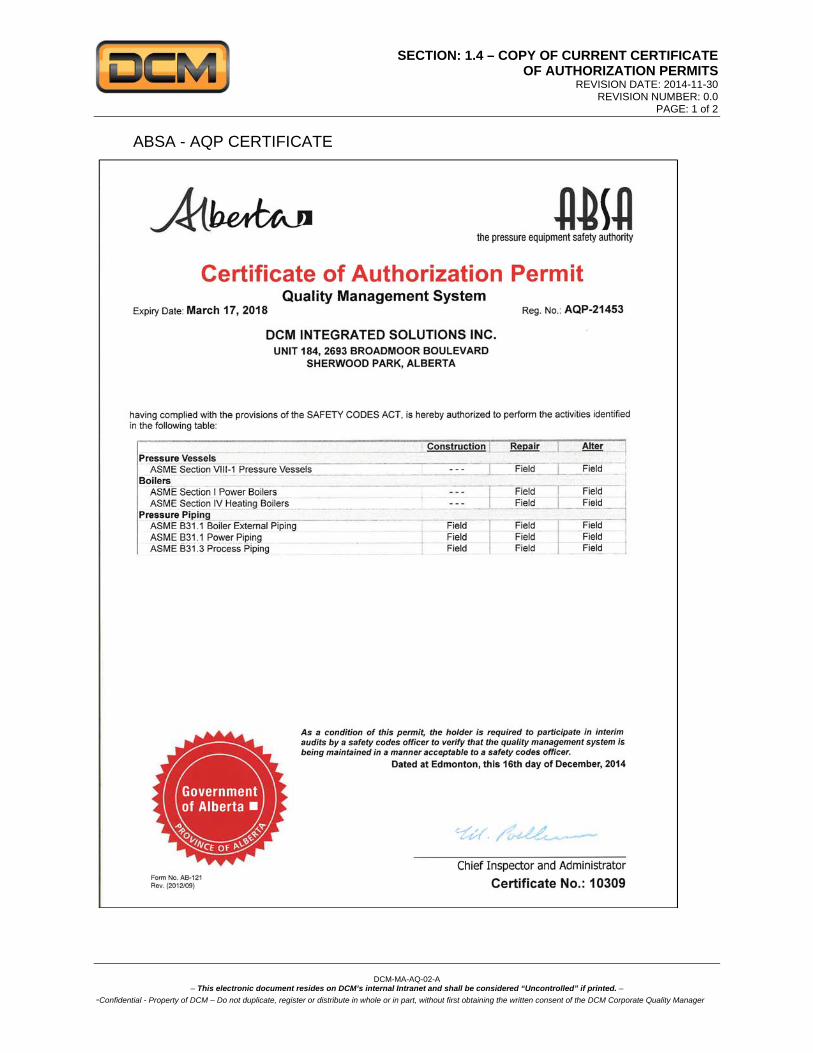
ABSA - AQP CERTIFICATE
SECTION: 1.4 – COPY OF CURRENT CERTIFICATE OF AUTHORIZATION PERMITS
REVISION DATE: 2014-11-30 REVISION NUMBER: 0.0
PAGE: 2 of 2
DCM-MA-AQ-02-A
– This electronic document resides on DCM’s internal Intranet and shall be considered “Uncontrolled” if printed. –
-Confidential - Property of DCM – Do not duplicate, register or distribute in whole or in part, without first obtaining the written consent of the DCM Corporate Quality Manager
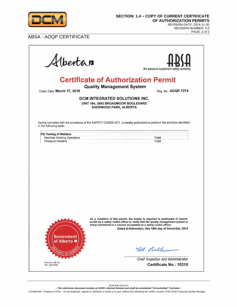
ABSA - AOQP CERTIFICATE

SECTION: 2.0 – SCOPE OF WORK REVISION DATE: 2014-11-30
REVISION NUMBER: 4.0 PAGE: 1 of 2
DCM-MA-AQ-02-A
– This electronic document resides on DCM’s internal Intranet and shall be considered “Uncontrolled” if printed. –
-Confidential - Property of DCM – Do not duplicate, register or distribute in whole or in part, without first obtaining the written consent of the DCM Corporate Quality Manager
2.0 SCOPE OF WORK 2.1 This Quality Manual describes the Quality Management System for pressure piping and equipment
as it applies to:
DCM Integrated Solutions Inc. #184, 2693 Broadmoor Blvd. Sherwood Park, Alberta T8H 0G1
2.2 The objective of this program is to identify, detect, and correct non-conformities, and to ensure that
the installation, alteration, and repairs of pressure piping, or the repairs and alterations to existing boilers, heating boilers, and pressure vessels, (designated work) are executed in accordance with the Alberta Safety Codes Act, Regulations, and the project Specifications.
2.3 The quality system, as described in this manual, applies to the work as described in the Certificate
of Authorization(s) issued by The Alberta Boiler Safety Association (ABSA). 2.4 The scope of work covered by this quality manual is defined as follows:
a. The installation, alteration and repair of piping that is subject to the ASME B31.1 Power Piping including Boiler External Piping and the B31.3 Process Piping Codes, the Alberta Safety Codes Act and Regulations, and project specifications;
b. Repairs and Alterations to existing power boilers, heating boilers and pressure vessels in accordance with the Alberta Safety Codes Act and Regulations, ABSA AB-513 document, and insofar as possible, with ASME Section I, ASME Section IV or ASME Section VIII, Division 1, as applicable;
c. Performance qualification testing of pressure welders and machine welding operators employed by DCM Inc. or one of its named affiliate companies, in accordance with ASME Section IX and the Alberta Safety Codes Act and Regulations;
At Field Sites controlled from the above noted address.
2.5 Named Affiliate Companies: The following represents the names of affiliate companies on behalf of DCM Integrated Solutions
Inc. under the scope of this program:
DLI Inc., #184, 2693 Broadmoor Blvd., Sherwood Park, AB, T8H 0G1 Solimec Construction Inc., 8315 Devonshire, Mont-Royal, QC H4P 2L1 Dawcolectric Inc., 8315 Devonshire, Mont-Royal, QC H4P 2L1 JYNT Fabrication Inc., 1420 rue Joliot-Curie, Boucherville, Québec, J4B 7L9
Note: All forms and pertinent documentation in accordance with this manual shall be issued in the name of DCM Integrated Solutions Inc.
2.6 Performance Qualification Testing of Pressure Welders and Machine Welding Operators
The following paragraph describes the procedure that will be used by DCM Inc. to conduct renewal performance qualification tests of Welders and Machine Welding Operators employed by DCM Inc. in accordance with the Alberta Safety Codes Act and Regulations and ASME Section IX.
SECTION: 2.0 – SCOPE OF WORK REVISION DATE: 2014-11-30
REVISION NUMBER: 4.0 PAGE: 2 of 2
DCM-MA-AQ-02-A
– This electronic document resides on DCM’s internal Intranet and shall be considered “Uncontrolled” if printed. –
-Confidential - Property of DCM – Do not duplicate, register or distribute in whole or in part, without first obtaining the written consent of the DCM Corporate Quality Manager
a. Welders/Machine Welding Operators shall be examined using welding procedures registered with ABSA.
b. Welders and Machine Welding Operators shall be qualified using guided bend tests or by radiographic examination. Radiographic examination shall not be used for the GMAW short circuit process.
c. DCM Inc. shall conduct performance qualification testing for our own employees or named affiliate companies only. DCM Inc. recognizes that when performance qualification cards are issued they are the property of the Welder/Machine Welding Operator and are valid if the Welder/Machine Welding Operator leaves the employment of DCM Inc. or its affiliated companies.
d. DCM Inc. will subcontract all heat treatment and non-destructive examination to approved vendors.
2.7 Welding Examiner Qualifications
The following paragraph establishes the minimum qualifications of Welding Examiners who conduct and supervise performance qualification testing of Welders/Machine Welding Operators for DCM.
a. The Corporate Quality Manager is responsible for appointing the Welding Examiner(s).
The CQM’s duties include: i. Verifying that the Welding Examiner(s) has the necessary qualifications, experience,
ability and education. ii. Maintaining a file for each Welding Examiner containing all relevant documentation
including a letter of appointment signed by a company official and accepted by signature of an ABSA Safety Codes Officer.
iii. Monitoring the standards employed by the Welding Examiner. iv. Providing written notification to ABSA, if any Welding Examiner’s employment is
terminated.
b. The Welding Examiner must hold a valid Welding Examiner Certificate of Competency issued by ABSA.
2.8 ABSA Safety Codes Officer
The following identifies the rights and responsibilities of the ABSA Safety Codes Officer. a. The Quality Manager or Quality Control Supervisor shall be responsible for liaison with the
ABSA Safety Codes Officer.
b. The ABSA Safety Codes Officer shall have access to areas where performance qualification testing of Welders/Machine Welding Operators is conducted. The AI shall have access to all documents and materials pertaining to Welder/Machine Welding Operator performance qualification tests described in this Manual.
SECTION: 4.0 MANUAL CONTROL AND REVISIONS REVISION DATE: 2014-11-30
REVISION NUMBER: 0 PAGE: 1 of 1
DCM-MA-AQ-02-A
– This electronic document resides on DCM’s internal Intranet and shall be considered “Uncontrolled” if printed. –
-Confidential Property of DCM, Do not duplicate, register or distribute in whole or in part, without first obtaining the written consent of the DCM Corporate Quality Manager
4.0 MANUAL CONTROL AND REVISIONS 4.1 The objective of this section is to define how the manual will be administered including the control
of new editions, reviews and revisions.
4.2 The Corporate Quality Manager (CQM) is responsible for the preparation, communication, distribution, and the updating of all controlled copies of the manual including revisions.
4.3 The CQM shall forward copies of the manual in accordance with the Manual Distribution List (form
F4.1). The control number that appears on the distribution list of the manual shall also appear on the first page of each manual.
4.4 The new editions and addendum to the Codes, Act, and Regulations of the Jurisdiction shall be
evaluated by the CQM in order to determine if revisions to the manual are required. The evaluations are documented with the aid of the Control of Reviews, Revisions, and Addendum (form F4.3). When revisions are required they will be submitted to the Authorized Inspector (AI) for his approval prior to distribution to the holders of the Manual within six (6) months of the publication of new edition and addendum.
4.5 All proposed revisions to this manual shall be approved by the CQM and submitted to the AI for
review and acceptance prior to being issued and implemented. All revisions shall be made by revising a section of the Manual with the exception of the forms, specimens, procedures, and processes which are individually controlled (Section A – Forms; Section B – Procedures; Section C – Processes).
4.6 The revised sections of the manual shall be distributed by the CQM to the outside holders of the
manual as outlined in the Manual Distribution List (form F4.1), including a revised table of contents page indicating the date and the number of the last revision of each section of the manual with the date and signature of CQM and the AI.
4.7 All revisions to this manual shall be completed by the replacement of the outdated section or
sections with the number of the revision indicated in the table of contents. Any revision to a form shall be made by replacing it and indicating the number of the revision at the bottom of the page as described in above paragraph 4.5.
4.8 Revisions shall be indicated by a vertical line in the right margin beside the revised paragraph or
paragraphs. 4.9 Any discrepancies identified between the copies of the manual; the AI copy shall take precedence. 4.10 The latest controlled copy of the manual is available for review by the AI at each job site of an
active project, this controlled electronic copy shall be available on “Eliot” DCM’s Company Intranet. 4.11 All printed manuals from Eliot shall be considered “uncontrolled” when printed. 4.12 The Manual Revision Notice form (F4.2) will be used as a transmittal letter for the distribution of the
Quality Manual and its’ revisions to the outside holders of controlled copies. For internal controlled copies, the CQM will make the changes by hand in each copy.
Forms:
F4.1 Manual Distribution List
F4.2 Manual Revision Notice
F4.3 Reviews, Revisions, and Addendum Control
SECTION: 5.0 - ORGANIZATION & RESPONSIBILITY REVISION DATE: 2014-11-30
REVISION NUMBER: 4.0 PAGE: 1of 3
DCM-MA-AQ-02-A
– This electronic document resides on DCM’s internal Intranet and shall be considered “Uncontrolled” if printed. –
-Confidential - Property of DCM – Do not duplicate, register or distribute in whole or in part, without first obtaining the written consent of the DCM Corporate Quality Manager
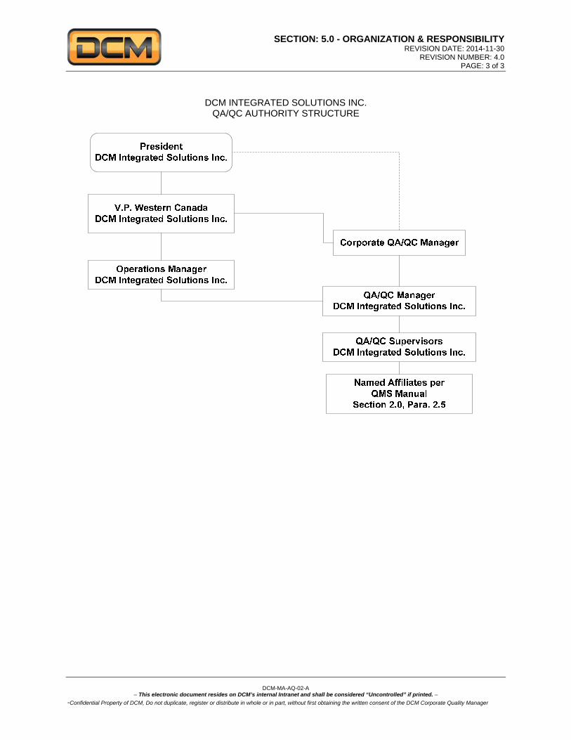
5.0 ORGANIZATION & RESPONSIBILITY 5.1 The organizational structure and lines of communication are shown on the attached Organizational
Charts.
a. All personnel have the authority to perform their duties as described in this manual. Managers and Superintendents may delegate the performance of duties to those who report to them provided that they are qualified (and where required “certified”) to perform the duties, however, the Manager or Superintendent shall retain the responsibility.
b. The Corporate Quality Manager has overall responsibility for the effective implementation of the quality manual.
c. For a project scope too small to logistically justify full-time QC personnel, the Corporate
Quality Manager shall assign a resource to the project and maintain functional oversight to ensure the designated person is competent in performing the required the functions.
5.2 Management Responsibilities
a. DCM Inc. management is committed to the development and implementation of a successful pressure piping and repair/alteration program and will endeavor to continually improve the effectiveness of the program.
b. The pressure piping construction program will be reviewed by management yearly to ensure the program is suitable and effective to the activities being performed.
c. Management will determine and provide adequate and competent resources, necessary
facilities and equipment to effectively implement the pressure piping construction activities.
d. DCM Inc. is committed to creating an environment that encourages the involvement of personnel in the development of the quality processes.
e. DCM Inc. will ensure that responsibilities and authorities are defined and are
communicated within the organization.
f. Individuals responsible for visual inspection shall be qualified in accordance with the requirements of the contract, the local Jurisdiction, the Code, Act and Regulations and shall only undertake the work for which they are qualified and certified.
g. Inspection personnel’s certification shall be kept on file and available for the AI’s for review.

SECTION: 11.0 – WELDING MANAGEMENT REVISION DATE: 2014-11-30
REVISION NUMBER: 4.0 PAGE: 1of 6
DCM-MA-AQ-02-A
– This electronic document resides on DCM’s internal Intranet and shall be considered “Uncontrolled” if printed. –
-Confidential Property of DCM, Do not duplicate, register or distribute in whole or in part, without first obtaining the written consent of the DCM Corporate Quality Manager
SECTION: 5.0 - ORGANIZATION & RESPONSIBILITY REVISION DATE: 2014-11-30
REVISION NUMBER: 4.0 PAGE: 3 of 3
DCM-MA-AQ-02-A
– This electronic document resides on DCM’s internal Intranet and shall be considered “Uncontrolled” if printed. –
-Confidential Property of DCM, Do not duplicate, register or distribute in whole or in part, without first obtaining the written consent of the DCM Corporate Quality Manager
DCM INTEGRATED SOLUTIONS INC. QA/QC AUTHORITY STRUCTURE

SECTION: 6.0 – CONTRACT REVIEW REVISION DATE: 2014-11-30
REVISION NUMBER: 4.0 PAGE: 1 of 1
DCM-MA-AQ-02-A
– This electronic document resides on DCM’s internal Intranet and shall be considered “Uncontrolled” if printed. –
-Confidential Property of DCM, Do not duplicate, register or distribute in whole or in part, without first obtaining the written consent of the DCM Corporate Quality Manager
SECTION: 6.0 – CONTRACT REVIEW
6.1 The objective of this section is to describe the process to ensure that contract requirements are
defined and agreed upon prior to the start of work. 6.2 The Project Manager shall review the contract/purchase order prior to acceptance, to ensure that
requirements are adequately defined. When requirements are inadequately defined or there is no written contract/order the Project Manager shall contact the client to ensure requirements are stated and agreed upon, and shall record the information in the job file.
a. The Project Manager, or assigned designate, shall ensure that:
The scope of work is defined, including the applicable code of construction and
service (e.g. ASME B31.3 service category). Drawings are approved for construction, assembly, repair or alteration, and the
responsible party for design and design submission for registration by ABSA is/are identified.
The material list including ASME material specification numbers (or other specification allowed by the code of construction), grades, material thickness, schedules, classes and sizes (as applicable), is provided.
The welding procedures are specified and qualified for the job. The degree and type of NDE and the determination of “Lot Sizes” shall be agreed
upon. The type of pressure test is defined, and responsibility for these requirements is
assigned. The responsibility for material procurement is defined. The responsibility for Piping Lot Size are specified by the Owner and agreed upon
before the start of fabrication. The responsibility for Post Weld Heat Treatment is defined. The requirements of a Turnover Package and contents thereof are agreed upon The certification of construction using the ABSA AB-83 Data Report form (Partial or
Final) or AB-83F for piping fabricated outside of Alberta is agreed upon between the contracting parties.
The responsibility for certifying the installation and readiness for operation using the ABSA AB-81 form is identified.
6.3 The Project Manager shall obtain written verification defining responsibility for the above activities from the owner or Owners Agent using the Contract Review Form (form DCM-FO-AQ-117-A).
Forms:
DCM-FO-AQ-117-A Contract Review Form
SECTION: 7.0 – DRAWINGS SPECIFICAITONS, & DESIGN CONTROL
REVISION DATE: 2014-11-30 REVISION NUMBER: 4.0
PAGE: 1 of 2
DCM-MA-AQ-02-A
– This electronic document resides on DCM’s internal Intranet and shall be considered “Uncontrolled” if printed. –
-Confidential Property of DCM, Do not duplicate, register or distribute in whole or in part, without first obtaining the written consent of the DCM Corporate Quality Manager
7.0 DRAWINGS, SPECIFICATIONS, & DESIGN CONTROL 7.1 The objective of this section is to outline the responsibilities and procedures used for distribution,
control, and revisions of drawings, calculations, and specifications, in order to ensure that the requirements of the Codes, Act, Regulations, and the project specifications are met.
7.2 At the time of tender the Chief Estimator (CE) is responsible for the verification of the specifications
and drawings which must be approved by the client’s engineer who shall confirm that the design conforms to the applicable Codes, Act, Regulations, and project Specifications.
7.3 In the case where the design is the responsibility of DCM Inc., the calculations and drawings will be
subcontracted to a firm specializing and licensed in Design Engineering. 7.4 All the documents supplied by the Design Engineer (DE) shall be reviewed and approved by the
Project Manager (PM) or Site Supervisor (SS) of DCM Inc. 7.5 When Spool drawings or “Cut Sheets” are prepared by DCM or its subcontractors, the drawings or
cut sheets shall reference the owner’s or client supplied construction or design drawing numbers.
7.6 The Site Supervisor shall ensure that the individual components listed on the Cut Sheet Bill of Materials (BOM) meet the requirements of the spool drawings and are traceable to the Material Test reports by recording the heat number of each component next to the item listed on the Cut Sheet Bill of Material.
7.7 For new editions of the Codes and for the annual review of the addendum, the Client or the DE
shall incorporate any changes in design. After the issue of a new or revised Code form (F4.3) will be up-dated and distributed to all of the holders of the manual form (F4.1).
The following information must appear on the drawings and specifications: Applicable Code(s) with current edition and addendum The list of material including the material specification, type, grade or class, as required in the
applicable section of the Code. ASME B31.3 fluid category for process piping Weld designs and locations Bolted joint details Maximum and minimum Design pressures and temperatures. Operating pressures and temperatures when available. Hydrostatic or pneumatic testing, as required. Type and extent of NDE requirements Preheat and Post Weld Heat Treatment (PWHT) of welds if required. All other requirements of the Code. Project number. Drawing number and revision Each piping class shall refer to an Alberta Piping Registration Number (PRN) to ensure that
the design is registered with the Province.
7.7 If requested, the design calculations, drawings and specifications shall be made available to the AI for review.
7.8 The Quality Control Supervisor (QCS) is responsible for the control of the distribution of the
drawings and specifications as well as their revisions using the Drawing and Specification Control (form DCM-FO-AQ-101-A). Alternatively the distribution may be made using the clients’ form.

SECTION: 7.0 – DRAWINGS SPECIFICAITONS, & DESIGN CONTROL
REVISION DATE: 2014-11-30 REVISION NUMBER: 4.0
PAGE: 2 of 2
DCM-MA-AQ-02-A
– This electronic document resides on DCM’s internal Intranet and shall be considered “Uncontrolled” if printed. –
-Confidential Property of DCM, Do not duplicate, register or distribute in whole or in part, without first obtaining the written consent of the DCM Corporate Quality Manager
7.9 When a drawing or specification is revised, the distribution is controlled as per paragraph 7.8. All
out-dated documents shall be identified as void or shall be destroyed by the QCS. Documents of external origin shall be identified as per paragraph 7.4 and 7.8 respectively.
7.10 After completing a project one (1) copy of the last revision of the project documents will be maintained for reference. The latest revision of the construction drawings shall be identified “as built” by the QCS.
7.11 Internal distribution of the drawings and specifications will be accomplished as follows:
one copy to the CE (for tender only) one copy to the QCM /QCS one copy to the PM one copy to the SS one copy to the Subcontractor (if required) three copies to the Jurisdiction (if required).
7.12 Any questions raised by the AI concerning the design calculations will be answered by the CQM or
the Project Manager. 7.13 Each project will be assigned a unique and sequential number that shall be identified in the
contracts register by the Administrative Assistant (AA). 7.14 When required, the CQM or PM will ensure that the project drawings, design calculations, and the
specifications, are reviewed and transmitted to the Jurisdiction for registration. Forms: DCM-FO-AQ-101-A Drawing and Specification Control

SECTION: 8.0 - MATERIAL CONTROL REVISION DATE: 2014-11-30
REVISION NUMBER: 4.0 PAGE: 1 of 4
DCM-MA-AQ-02-A
– This electronic document resides on DCM’s internal Intranet and shall be considered “Uncontrolled” if printed. –
-Confidential Property of DCM, Do not duplicate, register or distribute in whole or in part, without first obtaining the written consent of the DCM Corporate Quality Manager
8.0 MATERIAL CONTROL 8.1 The objective of this section is to ensure that DCM or Owner supplied materials used in fabrication
and/or construction conforms to the requirements of the Codes, Act, Regulations, and Project Specifications for the designated work.
8.2 For DCM supplied materials, the Site Supervisor (SS) or designated Shipping Receiving
Supervisor (SRS) is responsible for completing the Material Requisition form (DCM-FO-AP-03-A) in accordance with the Owners material lists on the approved drawings and specifications. The Purchasing Coordinator is responsible for managing all requisitions and
The Purchasing Department (PD) is responsible for reviewing the requisitions and completing the Purchase Orders (e.g. Specimen S8.1 & S8.2) and for transmitting the information to the suppliers. A copy of the purchase order will be forwarded to the supplier (when required).
8.3 The Site Supervisor is responsible for the purchase of filler metals for welded joints. A Material
Requisition (form DCM-FO-AP-03-A) shall be completed, reviewed by the QCS, and transmitted to the PD who will then complete the purchase order and transmit the information to the suppliers. A copy of the purchase order will be forwarded to the supplier (when required).
8.4 The purchase order (Specimen S8.1) must include (or be attached to) the following information:
The project number The description and quantity of the materials to be ordered. The material ASME or acceptable ASTM specifications, grade, type or class if applicable and
if required by all special requirements. Supplementary requirements such as heat treatment (ie: Normalized) special chemistry etc. Requirements for obtaining the applicable material certification, such as mill test certificates,
letters of conformity, etc. Requests for Manufacture’s Data Reports for all Code stamped and welded parts supplied by
others. Requirement that the fittings are registered with ABSA and have a valid CRN for installation in
Alberta. Welding consumables must be ordered using SFA or AWS classification as required by the
welding procedure to be used.
8.5 For Owner or Client supplied materials, a copy of the completed purchase order (or material list with details and information required in 8.4 above) traceable to the purchase order number is distributed to the PM (or the SS) and the Shipping Receiving Supervisor (SRS).
8.6 Any alterations or revisions to a purchase order must be completed in accordance with the original
issuing and distribution procedures described in this section of the manual. 8.7 The SRS shall ensure that all pipe, piping components, and material, (including welding
consumables) are held in a receiving area until identified with the project number and inspected by the Quality Control Inspector. All welding consumables must be provided with Certificates of Conformance, the QC shall initial these documents and forward to the QC Assistant for filing in the job file.
8.8 Using the purchase order / requisition, along with the receiving inspection form (DCM-FO-AQ-07-
A), the QCS & SRS will be responsible to verify that the material received conforms to the specifications, dimensions and quantities and has no visual defects. The SRS shall also ensure that material received is identified with the project number. The Quality Control Inspector shall ensure that Welding consumables received comply with the Purchase Order and are identified with the manufacturer’s name, SFA specifications, AWS classification and size. Unidentified containers or electrodes are unacceptable and are to be returned to the supplier or discarded.

SECTION: 8.0 - MATERIAL CONTROL REVISION DATE: 2014-11-30
REVISION NUMBER: 4.0 PAGE: 2 of 4
DCM-MA-AQ-02-A
– This electronic document resides on DCM’s internal Intranet and shall be considered “Uncontrolled” if printed. –
-Confidential Property of DCM, Do not duplicate, register or distribute in whole or in part, without first obtaining the written consent of the DCM Corporate Quality Manager
8.9 Material traceability is required. For ASME Code work, (i.e.: B31.1, Section 1 and Boiler External
Piping (BEP), the PD shall attach DCM’s additional purchasing instructions (Specimen S8.2 Attachment C) to the purchase order for all Code material. Upon receipt of the material and MTR’s, the QCS shall verify that the mill test certificates and filler metal certificate of conformance conform to all applicable specifications including ASME Section II Part A and Part C. The PD and QCS must also ensure that CRN numbers have been provide when requested.
8.10 Acceptance of the material is documented on the copies of the packing slips, Receiving Inspection
Report form (DCM-FO-AQ-17-A), as well as the mill test certificates and certificates of conformance. Once the QCS signs and dates the packing slips then the material is considered accepted. The documents must be placed in the project quality file and be available for review by the AI.
8.11 In the case where one or more pieces of material do not conform to the purchase specifications
and are examined and evaluated by the QCS to be not acceptable to the purchasing specifications the material must then be clearly marked “NC”. The QCS will complete a Non-Conformance Report, form (DCM-FO-AQ-01-A), and will forward a copy to the PD who will then advise the supplier. The procedure to be followed for nonconforming material is described in Section 17.0 of this manual.
8.12 Non-conforming materials shall be stored in a quarantine area while awaiting a decision on the
corrective action. The procedures described in section 17.0 of this manual shall be followed. Material or equipment that is too large to be moved or that has been placed in a quarantine zone will be identified with a Hold Tag (Exhibit 8.2)
8.13 After the material is received and approved, copies of the mill test certificates will be forwarded to
the client or the DE to confirm their approval (if required). 8.14 The QCS or the Administrative Assistant (AA) is responsible for the filing of the mill test certificates
and welding consumable certificates of conformance in the quality file of each respective project. 8.15 The QCM/QCS and QCI shall ensure that only fully identified material spec and grade and / or
colour code accepted material is used for the designated work. 8.16 All documents referred to in this section of the Manual are to be made available for review by the AI
and/or the client as required. 8.17 Any additional tests on materials that may be required upon receipt or during the installation shall
be indicated on the ABSA AB-83 Piping Data Report (latest revision from the ABSA website). 8.18 Filler metals shall be stored in a clean, dry, and warm environment such as a warehouse or heated
shipping container with controlled access, all piping material and consumables taken from the warehouse inventory shall be re-inspected by the QCS in order to verify that it meets the project specifications. The requirements of articles 8.8 to 8.11 must be repeated during the inspection.
8.19 Material Segregation:
a. The SS in conjunction with the QCS are responsible for ensuring that all pipe material is either physically segregated, manually marked by stamp or paint stick, or is colour coded by a paint stripe over the full length, depending on the projects complexity and requirements.
SECTION: 8.0 - MATERIAL CONTROL REVISION DATE: 2014-11-30
REVISION NUMBER: 4.0 PAGE: 3 of 4
DCM-MA-AQ-02-A
– This electronic document resides on DCM’s internal Intranet and shall be considered “Uncontrolled” if printed. –
-Confidential Property of DCM, Do not duplicate, register or distribute in whole or in part, without first obtaining the written consent of the DCM Corporate Quality Manager
b. The Colour Code Marking chart (Exhibit 8.1) may be established for a project if so
determined by the CQM, QCM or QCS.
c. The QCS is responsible for ensuring that the correct colour code is provided to site personnel and that the Colour Coded Markings chart is available to all project personnel and that it is posted where required.
d. If required by the owner’s specifications, an alternate colour code may be used or the material specification and grade shall be marked on each piece, prior to the cut.
8.21 Preservation Requirements
a) Client supplied equipment including rotating equipment, vessels, exchangers, meter runs and both DCM and Vendor spools shall be checked for preservation requirements and stored in accordance with the manufacturer’s recommendations. Preservation requirements shall be indicated on the Material Receiving Report and all Original Equipment Manufacturer (OEM) manuals shall be forward to document control department for inclusion into the Field Installation Work Packages. (FIWP)
b) Piping spools shall be stored on dunnage, adequately supported and shall have all openings covered. Flange faces on spools shall be covered and protected from damage.
c) The QCS and SRS shall ensure that all Stainless Steel spools shipped by road way on flat decks are adequately protected from road salt contamination. Spools that have been contaminated shall be quarantined and cleaned prior to installation.
d) Stainless Steel piping spools, components and materials shall be stored separately from Carbon Steel to avoid cross contamination
8.22 Performance Qualification Testing
a. Material and consumable control including ordering, identification, receiving, storing, issuing, controlling, and traceability of materials used for Welder/Machine Welding Operator performance qualification testing shall be in accordance with the following paragraphs:
b. The Welding Examiner (WE) is responsible for receiving and storing all the material used
for performance qualification testing. The Examiners duties include:
c. Inspecting all received material for damage and correct material identification and thickness against purchase order.
d. Physical segregation, manually marking or colour coding, cutting, machining and storing the material in a manner that will maintain traceability.
e. Checking the material test report to ensure that it meets the requirements of ASME Section
II Part A and Part C.
f. Checking that all welding consumables received comply with the Purchase Order and are identified with the manufacturer’s name, SFA specifications, AWS classification and size. Unidentified spools, containers, or electrodes are unacceptable and are to be returned to the supplier or discarded.
g. Ensuring that all welding consumables are stored according to the manufacturer’s
specification until they are used.

SECTION: 8.0 - MATERIAL CONTROL REVISION DATE: 2014-11-30
REVISION NUMBER: 4.0 PAGE: 4 of 4
DCM-MA-AQ-02-A
– This electronic document resides on DCM’s internal Intranet and shall be considered “Uncontrolled” if printed. –
-Confidential Property of DCM, Do not duplicate, register or distribute in whole or in part, without first obtaining the written consent of the DCM Corporate Quality Manager
Forms:
DCM-FO-AP-03-A Material Requisition
DCM-FO-AQ-01-A Non Conformance Report
DCM-FO-AQ-07-A Receiving Inspection Report
DCM-FO-AQ-08-A Over Short or Damaged Report
Exhibits:
Exhibit 8.1 Colour Coded Marking Chart
Exhibit 8.2 Hold Tag
Specimen:
S8.1 DCM Purchase Order – Specimen
S8.2 Attachment C ASME Code Material Requirements
External Forms:
AB-83 Pressure Piping Construction and Test Data Report

SECTION: 8.0 - MATERIAL CONTROL REVISION DATE: 2014-11-30
REVISION NUMBER: 4.0 PAGE: 1 of 1
DCM-MA-AQ-02-A
– This electronic document resides on DCM’s internal Intranet and shall be considered “Uncontrolled” if printed. –
-Confidential Property of DCM, Do not duplicate, register or distribute in whole or in part, without first obtaining the written consent of the DCM Corporate Quality Manager
EXHIBIT 8.1 COLOUR CODED MARKINGS CHART
SECTION: 9.0 - WORK METHODS REVISION DATE: 2014-11-30
REVISION NUMBER: 4.0 PAGE: 1 of 2
DCM-MA-AQ-02-A
– This electronic document resides on DCM’s internal Intranet and shall be considered “Uncontrolled” if printed. –
-Confidential Property of DCM, Do not duplicate, register or distribute in whole or in part, without first obtaining the written consent of the DCM Corporate Quality Manager
9.0 WORK METHODS 9.1 The objective of this section is to ensure that the designated work conforms to the Code, Act,
Regulations, and project Specifications.
9.2 The CQM is responsible for the implementation and maintenance of the inspection program as including the test procedures.
9.3 The QCS is responsible for ensuring that the designated work is verified and examined according to
the requirements of the Quality Plan ITP, and the associated checklists. The QCS shall be authorized to carry out any additional inspections as deemed necessary during the project to ensure workmanship and materials meet the requirements of the Code, Act, Regulations and client Specifications.
9.4 The ITP form (DCM-GU-AQ-02-A) shall identify the type and extent of inspections and tests
required. For all work including piping that is associated with boiler external piping in the Province of Alberta. The Inspection and Test Plan shall be submitted to the AI or Client’s Inspector for review and Hold Point identification prior to commencing the work.
9.5 Following the work progress, each inspection point must be signed and dated on the ITP in order to
indicate that the work has been accepted. 9.6 The Site Supervisor (SS) is responsible to advise the QCS prior to arriving at an HP. 9.7 All revisions to the ITP or Checklists must be done in accordance with the original issuing
procedures. 9.8 The Piping System Check List form (DCM-FO-AQ-125-A) shall be completed prior to testing any
piping system and shall be verified as complete by the QCI. The form shall contain the following information:
The project number Client’s name Service System or Line number References to Code and Specifications The Test Package Number The requirements for permanent line identification A column reserved for the signature and inspection dates carried out by the QCI and the client
(when required). 9.9 The QCM / QCS are responsible for completing, reviewing, and endorsing the ABSA (AB-83) Partial
and / or Final Data Report for all piping systems fabricated and tested by DCM, this includes the review and documenting of all AB-83 and AB83F (Partial Data Reports) for piping fabricated by others both inside and outside the province of Alberta.
9.10 The QCS is responsible for supervising and documenting of all “in-process” examinations tests,
and final inspections. 9.11 The QCS shall ensure that all DCM and vendor spool documentation is reviewed, fully identified,
complete, and correct, this verification shall include the review of vendors AB-83, AB83F Data Reports to ensure all NDE, PWHT and hydro tests are complete, correct, and available for the AI and Client for review prior to installation.

SECTION: 9.0 - WORK METHODS REVISION DATE: 2014-11-30
REVISION NUMBER: 4.0 PAGE: 2 of 2
DCM-MA-AQ-02-A
– This electronic document resides on DCM’s internal Intranet and shall be considered “Uncontrolled” if printed. –
-Confidential Property of DCM, Do not duplicate, register or distribute in whole or in part, without first obtaining the written consent of the DCM Corporate Quality Manager
9.12 The ABSA (AB-83) Data Report form shall contain the following information:
Constructed by: DCM Inc. and the Owner’s Job number Certificate of Authorization Permit No. AQP & Expiry date Owner’s name & address & Location of Installation Piping Design Registration Number (PP) Design Responsibility is defined (either owner or contractor) Welding Procedure Number for WPS’s used in fabrication or construction Code of Construction Drawing number, Revision number, and Line Number Process Fluid, Design Pressure & Design Temperature Test Pressure / Test Medium Pipe Material Spec & Grade Corrosion Allowance Pipe NPS & Schedule Flange Material and Rating PWHT Preheat Temperature NDE Partial Data Reports
9.13 The QCM / QCS shall be responsible for completing the ABSA AB-81 Completion of Construction
Declaration for all construction, installation, testing, and inspection of pressure piping systems. The AB-81 shall include the piping system registration number and ABSA tracking number for the piping system. The QCM / QCS shall sign the AB-81 upon completion of the piping system and ensure it is filed in the job file.
9.14 The weld traceability and the material traceability must be indicated or documented on the isometric or equipment drawings (Weld Maps) by the QCS.
9.15 For Weld and NDE tracking, DCM may choose to use their Microsoft Access Piping Data Base (DCMTRACK) to monitor, record, and document the following activities:
Progression of work per item ( pipe weld/ bolt up/ spool/ valve/ structural welds NDE Calculations for percentage for line class and welder Manage NDE by Lots Provide status reports for completed welds and NDE Manage interdisciplinary releases between departments for piping, heat trace, and insulation AB-83 Supplementary Attachment
9.16 Alternatively, for smaller projects or where warranted, weld traceability may be recorded on the
Weld Report form (DCM-FO-AQ-104-A) depending on the type of project.
9.17 The QCS shall ensure that all prefabricated pressure piping is supplied with an AB-83, or AB-83F Piping Data Report (Signed by a National Board Inspector)
Forms:
DCM-FO-AQ-132-A Piping System Check List
DCM-FO-AQ-104-A Weld Report
DCM-GU-AQ-02-A Inspection and Test Plan
External Forms:
ABSA AB-83 Pressure Piping Construction and Test Data Report ABSA AB-81 Completion of Construction Declaration

SECTION: 10.0 – REPAIR & ALTERATIONS TO BOILERS & PRESSURE VESSELS
REVISION DATE: 2014-11-30 REVISION NUMBER: 4.0
PAGE: 1 of 7
DCM-MA-AQ-02-A
– This electronic document resides on DCM’s internal Intranet and shall be considered “Uncontrolled” if printed. –
-Confidential Property of DCM, Do not duplicate, register or distribute in whole or in part, without first obtaining the written consent of the DCM Corporate Quality Manager
SECTION: 10.0 – REPAIR & ALTERATIONS TO BOILERS & PRESSURE VESSELS 10.1 This section describes the system for controlling the repairs and alterations of existing boilers and
pressure vessels. All other sections of this Quality Control Manual shall apply for repairs and alterations, except as modified in this section.
10.2 All repairs and alterations shall be in accordance with the Alberta Safety Codes Act, ABSA AB-513
document, and, insofar as possible, ASME Section I, ASME Section IV or ASME Section VIII Div 1, as applicable.
10.3 The CQM or designate will develop a written procedure for all repairs and alterations containing the following information:
Boiler or pressure vessel description Year built A number CRN Manufacturer Owners name and Owner's boiler or pressure vessel identification number when applicable Location of pressure vessel or boiler Detailed description of the repair and alteration methods Weld details Welding procedure specification number Material used by specification number, grade, and size NDE requirements PWHT requirements Pressure test requirements Any additional requirements
The repair or alteration report ABSA (AB-40) or ABSA AB-230 may be used to detail the repair or alteration procedure as applicable.
10.4 The information required for developing the procedure identified in paragraph 10.3 above may be found on the nameplate or the Manufacturer’s Data Report (MDR) which should be available from the owner.
10.5 The CQM or designate shall obtain acceptance of the repair or alteration procedure from the ABSA
Safety Codes Officer prior to the start of work. When required by the ABSA Safety Codes Officer, this procedure shall be submitted to the ABSA Design Survey Section for acceptance. The CQM or designate shall ensure copies of all latest repair or alteration procedures, drawings and instructions are provided to the personnel responsible for the repair or alteration.
10.6 ABSA Authorized Owner / User Pressure Equipment Integrity Quality Management Systems
a. When field or plant site repairs are performed for an organization with a valid Certificate of Authorization Permit issued by ABSA for an Owner-User Pressure Equipment Integrity Quality System, the CQM upon commencement of the contract, shall establish who will be responsible for the ASME Code inspections (either ABSA Safety Codes Officer or Owner-User Inspector performs ASME Code required inspections). See form DCM-FO-AQ-117-A Contract Responsibility.
b. The scope of the permitted Owner-User inspections is defined in the organization’s Pressure Equipment Integrity Quality Management System Manual and is limited to repairs done at their facilities only. An Owner-User may elect to have all repairs and ASME Code inspections conducted by ABSA.

SECTION: 10.0 – REPAIR & ALTERATIONS TO BOILERS & PRESSURE VESSELS
REVISION DATE: 2014-11-30 REVISION NUMBER: 4.0
PAGE: 2 of 7
DCM-MA-AQ-02-A
– This electronic document resides on DCM’s internal Intranet and shall be considered “Uncontrolled” if printed. –
-Confidential Property of DCM, Do not duplicate, register or distribute in whole or in part, without first obtaining the written consent of the DCM Corporate Quality Manager
c. The ABSA Safety Codes Officer and/or the Owner-User Inspector shall be notified prior to the start
of work to accept repair methods and designate any hold and inspection points. The ABSA Safety Codes Officer may require that the repair procedure be submitted to the ABSA Design Survey Section for acceptance.
d. The ABSA Safety Codes Officer and/or the Owner-User Inspector shall be notified of all
nonconformities.
e. The ABSA Safety Codes Officer or the Owner-User Inspector is required to inspect the repair and certify the repair or alteration report. DCM Inc. shall complete and certify this report for all repairs. Owner-User Certificate of Compliance shall also be obtained when applicable.
10.7 If the boiler or pressure vessel is still under warranty, the CQM or the QCM /QCS will contact the
Owner to obtain acceptance of the proposed work from the boiler or pressure vessel manufacturer. 10.8 For alterations, the Design Engineer (DE) will prepare detailed design calculations and drawings in
accordance with the applicable referenced ASME Code section. The CQM shall submit the alteration procedure, design calculations, and drawings to ABSA Design Survey Section for acceptance prior to starting work.
10.9 The PD is responsible for ordering all material. The PD shall prepare a Purchase Order form (Specimen S8.1) from the repair or alteration drawing or procedure. The purchase order shall include: Purchase Order number Material ASME specification number, grade, schedule, dimensions Request for material test reports for shells, heads, re-pads and other pressure retaining material
and pipe material used for pressure vessel shells. Request for partial data reports for welded parts supplied by others. Request for certification to ASME Section VIII, Division 1 paragraph UCS 79 (or paragraph UHT
79, where applicable) for cold formed heads, shells and other pressure parts cold formed from carbon and low alloy steel plates for pressure vessel use.
Instructions that a welding procedure qualified to ASME Sec IX must be used for all tack welds. Heat treatment requirements NDE requirements Statement that all fitting designs must be registered with the ABSA or the applicable jurisdiction
as required. Other job specifications
Any proposed material substitutions must be approved in writing by the Owner, the Designer and ABSA Safety Codes Officer, when applicable.
10.10 The Shipping and Receiving Supervisor (SRS) is responsible for receiving of all material.
The SRS duties include:
a. Checking all material received against the purchase order and packing slip for visible damage, correct identification, markings, dimensions, thickness, ASME material specifications and grade.
b. Identifying all acceptable material with a job number and highlighting the material specification and grade stamping by circling with a waterproof marker.
c. Verifying that the material is as specified on the drawings and conforms to ASME Code requirements.
d. Confirming that the material identification markings conform to the material test reports and/or partial data reports.
e. Ensuring that fittings are identified by job number and stored in the vicinity of the job.

SECTION: 10.0 – REPAIR & ALTERATIONS TO BOILERS & PRESSURE VESSELS
REVISION DATE: 2014-11-30 REVISION NUMBER: 4.0
PAGE: 3 of 7
DCM-MA-AQ-02-A
– This electronic document resides on DCM’s internal Intranet and shall be considered “Uncontrolled” if printed. –
-Confidential Property of DCM, Do not duplicate, register or distribute in whole or in part, without first obtaining the written consent of the DCM Corporate Quality Manager
10.11 The QCS is responsible for ensuring the identification and traceability of all materials, and duties
include:
a. Recording the material specification number, grade, thickness, etc. on the Repair or Alteration Examination and Inspection Sheet form (DCM-FO-AQ-105-A). In addition to this information heat and slab numbers shall be recorded for all shell, head and plate pressure retaining material, and any pipe used for pressure vessel shells.
b. Ensuring that material identification markings are transferred prior to dividing any material. This
identification shall be die stamped for carbon steel material 1/4" and over. For other material, identification shall be by waterproof marker.
c. Checking, with templates, the dish and knuckle radii of replacement formed heads.
d. Verifying that the material test reports include physical tests and chemical analysis and conform
to ASME Section II requirements. If the Material Test Reports (MTR’s) conform to ASME Section II Part A, the QCS will sign and date the MTR’s.
Note: Material Test Reports are required for all pressure retaining plate material and pipe shells.
e. Ensuring that all pipe material is identified by an approved means such as physical segregation, physical markings, or colour coded by a applying a paint stripe over the full length as stipulated in the material control section of this Quality Manual.
f. To ensure identification to the specification and grade, for product forms such as couplings and nozzle pieces and attachments, each piece may be marked or stamped with the specification and grade or a coded marking acceptable to the ABSA Safety Codes Officer (or Owner-User Inspector when applicable) may be used per Exhibit 10.1
10.12 The QCM/QCS are responsible for the examination and inspection program. These duties include:
a. Initiating a job file to include the Repair or Alteration Examination and Inspection Sheet, material reports, drawings, calculations, material test reports, non-destructive examination (NDE) reports, heat treatment (HT) reports, manufacturer’s data reports, and material receiving reports.
b. Initiating a Repair /Alteration Examination and Inspection form (DCM-FO-AQ-105-A) for each repair and alteration and presenting it to the ABSA Safety Codes Officer (and/or Owner- User Inspector when applicable) with drawings, specifications and calculations prior to the start of the job.
c. Notifying the ABSA Safety Codes Officer (and/or Owner-User Inspector when applicable) reasonably in advance of any hold points. Work shall not proceed beyond an established hold point until the ABSA Safety Codes Officer (and/or Owner-User Inspector when applicable) has released the hold by signing the Repair or Alteration Examination and Inspection Sheet.
d. Performing all examination functions specified on the Repair or Alteration Examination and
Inspection Sheet and signing and dating each function when it is completed.
e. Verify that applicable material is identified with specifications and heat numbers and that these
heat numbers are transferred and remain traceable throughout the repair or alteration.

SECTION: 10.0 – REPAIR & ALTERATIONS TO BOILERS & PRESSURE VESSELS
REVISION DATE: 2014-11-30 REVISION NUMBER: 4.0
PAGE: 4 of 7
DCM-MA-AQ-02-A
– This electronic document resides on DCM’s internal Intranet and shall be considered “Uncontrolled” if printed. –
-Confidential Property of DCM, Do not duplicate, register or distribute in whole or in part, without first obtaining the written consent of the DCM Corporate Quality Manager
f. Verify that material contains no visible defects and is as specified on the drawings or repair or
alteration procedure. If material nonconformities are found, the ABSA Safety Codes Officer (and/or Owner-User Inspector when applicable) must accept all material repair procedures prior to commencement.
g. Ensuring that material test reports are available for all pressure plate material and for all pipes used for pressure vessel shells and additional components as required by the customer.
h. Ensuring alignment tolerances are maintained during the repair or alteration.
i. Ensuring weld details are correct.
j. Non-destructive examination is performed in accordance with Section 11 of this Quality Control Manual and the referencing ASME Code Section.
k. Heat treatment instructions are prepared in accordance with Section 12 of this Quality Control
Manual and the referencing ASME Code Section, and heat treatment charts comply with instructions.
l. The correct hydrostatic test pressure, as indicated on the accepted repair or alteration
procedure, is applied. 10.12 When required by the ABSA Safety Codes Officer (and/or Owner-User Inspector when applicable),
an identification plate (Exhibit 10.2) will be attached to the pressure vessel or boiler adjacent to the pressure vessel or boiler manufacturer’s nameplate with the following information:
a. Repaired, Altered or Re-rated b. Name of repair or alteration organization c. Date of repair or alteration d. Maximum allowable working pressure and temperature e. Minimum design metal temperature and pressure (when applicable) f. CRN
10.13 Upon satisfactory completion of the repair or alteration report, the CQM or QCS shall complete and
certify the ABSA Repair/Alteration Report (AB-40) and present it to the ABSA Safety Codes Officer (and/or Owner-User Inspector, when applicable) for acceptance. A copy of the Repair or Alteration Report shall be provided to the ABSA Safety Codes Officer and the Owner.
10.14 The QCM/QCS shall assign a separate job number and file for each boiler or pressure vessel repaired or altered. The file will contain the following information:
a. Drawings & Calculations b. Repair or alteration procedure c. Purchase orders d. Material test reports e. NDE reports, radiographic film and copies of Examiners’ certifications f. Heat treatment instructions and charts g. Weld identification records (Welders/Machine Welding Operators qualification cards h. Non-conformance reports i. Examination and inspection sheets j. Repair or alteration report with partial data reports when applicable k. Pressure gauge/recorder calibration records

SECTION: 10.0 – REPAIR & ALTERATIONS TO BOILERS & PRESSURE VESSELS
REVISION DATE: 2014-11-30 REVISION NUMBER: 4.0
PAGE: 5 of 7
DCM-MA-AQ-02-A
– This electronic document resides on DCM’s internal Intranet and shall be considered “Uncontrolled” if printed. –
-Confidential Property of DCM, Do not duplicate, register or distribute in whole or in part, without first obtaining the written consent of the DCM Corporate Quality Manager
10.15 The job file shall be retained for a minimum of 5 years.
Forms:
DCM-FO-AP-105-A- Repair / Alteration Travel Sheet
Exhibits:
Exhibit 8.1 Colour Coded Marking Chart
Exhibit: 10.1 Coded Markings
Exhibit: 10.2 Sample Nameplate for Repairs or Alterations
Specimen:S8.1 DCM Purchase Order
External Forms:
ABSA Form: AB-40- Boilers and Pressure Vessels Repair or Alteration Report
ABSA Form: AB-230-General Engineering Requirements for Boilers & Pressure Vessels Repair &
Alteration
SECTION: 10.0 – REPAIR & ALTERATIONS TO BOILERS & PRESSURE VESSELS
REVISION DATE: 2014-11-30 REVISION NUMBER: 4.0
PAGE: 6 of 7
DCM-MA-AQ-02-A
– This electronic document resides on DCM’s internal Intranet and shall be considered “Uncontrolled” if printed. –
-Confidential Property of DCM, Do not duplicate, register or distribute in whole or in part, without first obtaining the written consent of the DCM Corporate Quality Manager
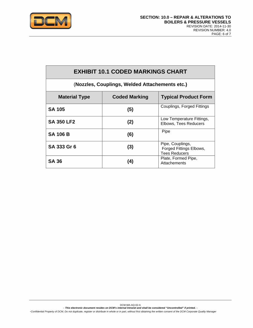
EXHIBIT 10.1 CODED MARKINGS CHART
(Nozzles, Couplings, Welded Attachements etc.)
Material Type Coded Marking Typical Product Form
SA 105 (5) Couplings, Forged Fittings
SA 350 LF2 (2) Low Temperature Fittings, Elbows, Tees Reducers
SA 106 B (6) Pipe
SA 333 Gr 6 (3) Pipe, Couplings, Forged Fittings Elbows, Tees Reducers
SA 36 (4) Plate, Formed Pipe, Attachements

SECTION: 10.0 – REPAIR & ALTERATIONS TO BOILERS & PRESSURE VESSELS
REVISION DATE: 2014-11-30 REVISION NUMBER: 4.0
PAGE: 7 of 7
DCM-MA-AQ-02-A
– This electronic document resides on DCM’s internal Intranet and shall be considered “Uncontrolled” if printed. –
-Confidential Property of DCM, Do not duplicate, register or distribute in whole or in part, without first obtaining the written consent of the DCM Corporate Quality Manager
EXHIBIT 10.2 SAMPLE NAMEPLATE FOR REPAIRS AND ALTERATIONS
by DCM Integrated Solutions Inc. (Identify Here the “Repair”
“Altered or “Rerated” as Applicable)
MAWP at temp. Indicate Units MDMT at pressure
CRN
Date work completed.
Note: Markings shall be produced by casting, etching, embossing, debossing, stamping or engraving.
Letters and numbers must be at least 5/32" high.
SECTION: 11.0 – WELDING MANAGEMENT REVISION DATE: 2014-11-30
REVISION NUMBER: 4.0 PAGE: 1of 6
DCM-MA-AQ-02-A
– This electronic document resides on DCM’s internal Intranet and shall be considered “Uncontrolled” if printed. –
-Confidential Property of DCM, Do not duplicate, register or distribute in whole or in part, without first obtaining the written consent of the DCM Corporate Quality Manager
SECTION: 11.0 - WELDING MANAGEMENT 11.1 The objective of this section is to establish the methodology for controlling and monitoring all welding
operations. All welding operations shall be performed in accordance this section of the manual, the requirements of ASME Section IX, and any additional requirements specified in other applicable sections of the Code of construction or project Specifications.
11.2 The Welding Procedures Specifications (WPS) including revisions shall be reviewed by the CQM or
QCM or QCS before being used in contracts for the fabrication, installation, alteration or repairs to pressure piping. The Welding Procedure numbers shall be recorded on the Repair Alteration Travel Sheets (DCM-FO-AQ-105-A), and/or Weld Report Traceability Maps (DCM-FO-AQ-104-A) and DCM’s Weld Track Data base as applicable.
11.3 The QCM / QCS shall ensure that all Welding, Visual Tests, PWHT, NDE, and Pressure Tests information is entered into DCM’s Microsoft Access Piping Data Base (DCMTRACK) to monitor, record, and document welding and associated activities.
11.4 The QCM / QCS is responsible for preparing, revising, and reviewing the WPS and PQR, the CQM is
responsible for submission, review, acceptance, and registration with ABSA Design Survey Department. 11.5 The QCM / QCS shall be responsible for the process of qualifying the WPS by the welding of a test
coupon as per the applicable Code. The QCM / QCS shall be responsible for preparing the test coupons, monitoring the welding, and recording the data obtained during the welding of the coupons. The QCM/QCS shall be responsible for advising the AI/ or Owner’s Inspector in advance of the testing to enable witnessing the welding of the coupons (if required). The qualification tests shall be sent to a third party laboratory for destructive testing. The CQM shall complete the procedure qualification record (PQR) and certify that the test results meet the requirements of the Code.
11.6 For each WPS the description of the welding method must contain the essential variables,
supplementary variables (when required) and non essential variables, as specifically outlined in Section IX of the ASME Code.
11.7 In order to adapt to the production requirements, changes to the description of the WPS can be made to
the non essential variables without having to re-qualify the procedure. These changes must however be documented, either by a revision to WPS or by the issue of a new WPS.
11.8 The CQM shall certify that the WPS conforms to section IX of the ASME Code and shall submit them to
the Jurisdiction for registration. The WPS and the PQR shall be made available for review by the AI. The AI has the authority to request a re-qualification of a welding procedure. The PQR must identify all of the actual variables used during the welding of the test coupon.
11.9 Copies of the WPS are issued to the PM, SS and the QCS and are to be made available to the welders.
The SS is responsible for training and supervising welders and for assigning them the appropriate work based on their certifications and competence. The QCS shall ensure that the welders are using the correct WPS that has been approved for the work. No welding can be undertaken on pressure piping until the WPS has been approved by the Jurisdiction and registered.
11.10 The QCM/QCS shall be responsible for specifying the WPS to be used and for submitting the WPS and
the Welding Matrix to the Client for acceptance prior to use. The WPS used for each stage of the work must be indicated on the applicable Isometric Drawings and be recorded in the DCM Weld Track Data Base.

SECTION: 11.0 – WELDING MANAGEMENT REVISION DATE: 2014-11-30
REVISION NUMBER: 4.0 PAGE: 2 of 6
DCM-MA-AQ-02-A
– This electronic document resides on DCM’s internal Intranet and shall be considered “Uncontrolled” if printed. –
-Confidential Property of DCM, Do not duplicate, register or distribute in whole or in part, without first obtaining the written consent of the DCM Corporate Quality Manager
11.11 When a WPS requires a name or address change the WPS must be revised with the new information
and revision number. The PQR will remain the same. The Welder Qualification (WQ) must be revised to reflect the new changes and must be dated and signed.
11.12 The QCM/QCS shall be responsible for organizing Welder Qualification (WQ) tests and renewals, the
QCS shall appoint a Welding Examiner (WE) to administer all Welder / Welding Operator Qualification tests. The WE shall provide each candidate with written test instructions B-Pressure Welder Recertification Checklist (DCM-FO-AQ-052 A) prior to the test; both the Welding Examiner and the Candidate shall sign and date the form acknowledging the established test requirements.
11.13 The WE shall record the data obtained during the test on the WQ test form (AB-76A). The test report
shall include the essential variables, the types of tests, the test results and the range of qualified thicknesses. The Welding Examiner shall witness each WQ test and certify the AB-76 form.
11.14 The AI retains the right to witness Welder / Welding Operator Qualification tests and reserves the right
to request re-qualification of a welder for cause. 11.15 The QCM/QCS shall provide each Welder with a unique identification symbol. Welders shall mark (with
paint marker), their identification number adjacent to the weld (spacing of ID shall not to exceed 1 m (3ft) intervals. QCM/QCS shall ensure the welder’s identification is transferred to the weld maps, / isometric drawings for each weld and entered into the DCM Weld Track Data Base or for small jobs documented on DCM-FO-AQ-104-A Weld Report Traceability Map.
11.16 The QCM/QCS shall maintain a list of welders on the Welder Qualification Continuity Register form
(DCM-FO-AQ-106-A). 11.17 Each month the QCM/QCS shall update the Welder Qualification Continuity Register with the project
numbers for each welding procedure used by the welders. 11.18 All welding procedures are to be made available to the welders for their information and review. 11.19 The validity of the Welder’s Qualifications may be affected by the following conditions:
a. When a welder has not performed any welding on a specific WPS for a period of six (6) months or more, his qualification for this procedure shall expire.
b. Should there be a reason to doubt that a welder has the ability to meet the requirements of the WPS, his certification shall be revoked.
11.20 Tack welds used to maintain joint alignment shall be completely removed once they are no longer
necessary. If the tack welds are to be incorporated into the final weld, then the start and stop areas shall be adequately prepared by grinding or other acceptable means.
11.21 Whether they are removed or not, all tack welds must be welded by qualified welders in accordance
with an approved WPS. Tack welds that are not removed must be visually examined and any visible defects must be removed.
11.22 The PM or the SS shall specify on the Material Requisition form (DCM-FO-AP-03-A) the type of filler
metals that are to be purchased. Only filler metals certified in accordance with ASME Code, section II, part C shall be purchased. The ASME designation for the filler metals must appear on the requisition form.

SECTION: 11.0 – WELDING MANAGEMENT REVISION DATE: 2014-11-30
REVISION NUMBER: 4.0 PAGE: 3 of 6
DCM-MA-AQ-02-A
– This electronic document resides on DCM’s internal Intranet and shall be considered “Uncontrolled” if printed. –
-Confidential Property of DCM, Do not duplicate, register or distribute in whole or in part, without first obtaining the written consent of the DCM Corporate Quality Manager
11.23 The purchased filler metals must conform to the type that is identified on the approved WPS. 11.24 Using the purchase order as a reference, the QCS or QCI shall verify all filler metals upon delivery
to ensure that: The quantity and description are as per the purchase order There is a reference to the applicable SFA The packaging seals are intact. They are not damaged
11.25 Once the filler metals have been accepted, the QCI shall mark each container with “QC OK”, the date,
and the inspector’s initials. The packing slip shall be signed, dated and kept in the project quality file. 11.26 In the case that the filler metals do not conform to the requirements mentioned in Para 11.23, they will
be removed from the site and/or from the warehouse and (for DCM purchased filler materials) given to the PD who will return them to the supplier. A non conformity report will be issued and processed as per section 16.0 of this manual.
11.27 The SS is responsible for the control of the welding consumables. The QCS shall monitor electrode
oven temperature on a regular but random basis. All filler metals must be stored at the manufacturer’s recommended temperature. Any package or container of filler metals that have been opened or unpackaged shall be stored and protected in order to prevent contamination from dirt, oil, grease, water, or elements.
11.28 Controlled Hydrogen (CH) filler metals that have been removed from their containers and are to be
used during the welding process shall be stored in portable ovens in order to maintain the manufacturer’s recommended stabilizing temperature. At the end of the welding process only clean filler metals that have been stored in functional portable ovens may be returned to the main ovens for re-use. Filler metals that are damaged, dirty or wet shall be discarded.
11.29 Special attention to the manufacturer’s recommendations shall be applied for filler metals with low or
controlled hydrogen content. 11.30 The Site Supervisor shall ensure portable electrode ovens are issued and controlled, confirm sufficient
inventory for number of welders, perform functional checks, and record portable oven issuance to the welders.
11.31 The QCS and Site Supervisor shall ensure that alloy electrodes are stored separately from non-alloy
electrodes. 11.32 Welding Inspectors shall examine the piping fit up to ensure that the bevel, root opening, and piping
alignment are acceptable, excessive hi-lo shall be transitioned in accordance with the governing Code of construction and the approved WPS.
11.33 Welding Inspectors shall indicate visual inspection status by marking each examined weld with the
following information: VT OK, the inspector’s initials, and date (as space permits) alternative methods may be used such as a ribbon system etc.
11.34 Named Affiliate Companies
For Welding Procedure Specifications and Welder Performance Qualifications Records qualified by a Named Affiliate Company (per this Manual Section 2.0, Para. 2.5), the following Code operations control requirements shall be satisfied:
SECTION: 11.0 – WELDING MANAGEMENT REVISION DATE: 2014-11-30
REVISION NUMBER: 4.0 PAGE: 4 of 6
DCM-MA-AQ-02-A
– This electronic document resides on DCM’s internal Intranet and shall be considered “Uncontrolled” if printed. –
-Confidential Property of DCM, Do not duplicate, register or distribute in whole or in part, without first obtaining the written consent of the DCM Corporate Quality Manager
a. Welding Procedure Specifications that are properly qualified by a Named Affiliate Company may be used, as submitted without deviation, by DCM Inc. after review and acceptance by the CQM to ensure that they comply with the Code of construction and ASME Section IX. Procedure Qualifications Records and all test documentation shall be part of the documents reviewed and accepted by the CQM. If changes to essential variables are required, the WPS shall be returned to the Named Affiliate Company for re-qualification. If DCM Inc. desires, they may re-qualify a new Welding Procedure Specification as specified in this Quality Manual.
i. DCM Inc. assumes all responsibility for Code compliance when using Welding
Procedure Specifications qualified by the Named Affiliate Companies. ii. Authority granted under ASME Code, Section IX, paragraph QW-201.
b. Welders qualified by a Named Affiliate Company may be used by DCM Inc. if the following conditions are satisfied:
i. A copy of the Welder’s original performance qualification record is on file with the
Company. ii. The Named Affiliate will submit a copy of the welder’s continuity record to DCM Inc. iii. Re-qualification can be required by the Named Affiliate Company or DCM Inc. iv. The CQM shall review and accept the qualification records for welders qualified by the
Named Affiliate Company before their use by the DCM Inc. v. DCM Inc. assumes all responsibility for Code compliance for Welders qualified by the
named Affiliate Company that are used by DCM Inc. vi. Authority granted under ASME Code, Section IX, paragraph QW-300.2.
11.35 Welder/Welding Operator Performance Qualification Testing
The following paragraphs detail the activities, procedures and requirements for performance qualification testing of Welders/Machine Welding Operators.
a. Responsibilities: i. The Corporate Quality Manager is responsible for implementing and maintaining this
procedure. ii. The CQM is responsible for appointing the Welding Examiner. iii. All parts of the performance qualification testing of Welders/Machine Welding
Operators shall be conducted and supervised only by those persons that have been appointed as a Welding Examiner. A Welding Examiner shall not issue a Performance Qualification Card to himself/herself.
b. Method: i. Prior to the performance qualification test, the Welding Examiner shall:
a. Review the candidate’s qualifications to ensure the candidate has an Alberta "B" Pressure Welder's Certificate of Competency, or Machine Welding Operator’s Certificate of Competency.
b. Make a photocopy of the candidate’s Certificate of Competency. c. Select the welding procedure to be used. d. Fill in the appropriate parts of the Welder/Welding Operator Qualification Record
(AB-76A or AB-76B). e. Issue a copy of the Performance Qualification Examination and Test Procedure
(DCM-PR-AQ-06-A) to the candidate. f. Issue a copy of the Welding Procedure Specification to the candidate. g. Assign a set of test coupons to the candidate and mark them with candidates
unique ID. h. Assign a test area to the candidate.
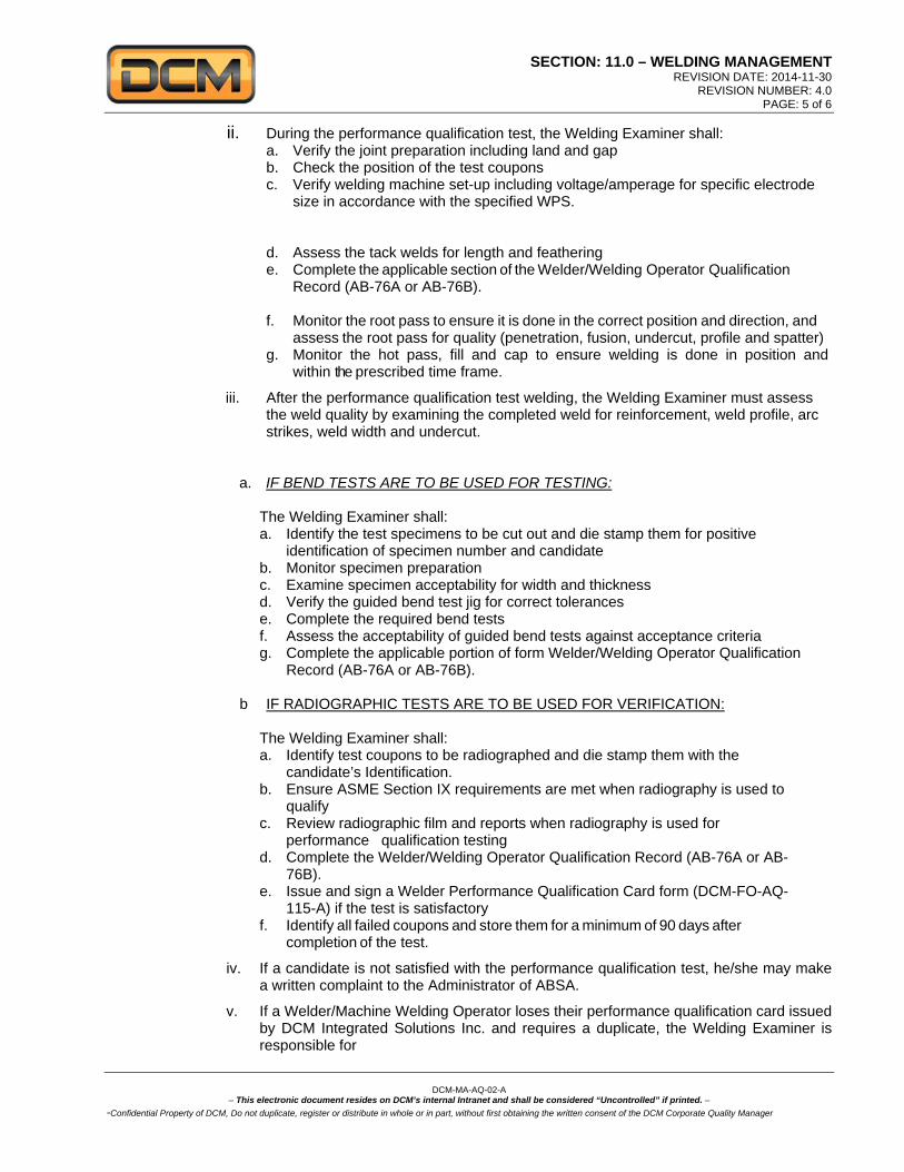
SECTION: 11.0 – WELDING MANAGEMENT REVISION DATE: 2014-11-30
REVISION NUMBER: 4.0 PAGE: 5 of 6
DCM-MA-AQ-02-A
– This electronic document resides on DCM’s internal Intranet and shall be considered “Uncontrolled” if printed. –
-Confidential Property of DCM, Do not duplicate, register or distribute in whole or in part, without first obtaining the written consent of the DCM Corporate Quality Manager
ii. During the performance qualification test, the Welding Examiner shall: a. Verify the joint preparation including land and gap b. Check the position of the test coupons c. Verify welding machine set-up including voltage/amperage for specific electrode
size in accordance with the specified WPS.
d. Assess the tack welds for length and feathering e. Complete the applicable section of the Welder/Welding Operator Qualification
Record (AB-76A or AB-76B).
f. Monitor the root pass to ensure it is done in the correct position and direction, and assess the root pass for quality (penetration, fusion, undercut, profile and spatter)
g. Monitor the hot pass, fill and cap to ensure welding is done in position and within the prescribed time frame.
iii. After the performance qualification test welding, the Welding Examiner must assess the weld quality by examining the completed weld for reinforcement, weld profile, arc strikes, weld width and undercut.
a. IF BEND TESTS ARE TO BE USED FOR TESTING:
The Welding Examiner shall: a. Identify the test specimens to be cut out and die stamp them for positive
identification of specimen number and candidate b. Monitor specimen preparation c. Examine specimen acceptability for width and thickness d. Verify the guided bend test jig for correct tolerances e. Complete the required bend tests f. Assess the acceptability of guided bend tests against acceptance criteria g. Complete the applicable portion of form Welder/Welding Operator Qualification
Record (AB-76A or AB-76B).
b IF RADIOGRAPHIC TESTS ARE TO BE USED FOR VERIFICATION:
The Welding Examiner shall: a. Identify test coupons to be radiographed and die stamp them with the
candidate’s Identification. b. Ensure ASME Section IX requirements are met when radiography is used to
qualify c. Review radiographic film and reports when radiography is used for
performance qualification testing d. Complete the Welder/Welding Operator Qualification Record (AB-76A or AB-
76B). e. Issue and sign a Welder Performance Qualification Card form (DCM-FO-AQ-
115-A) if the test is satisfactory f. Identify all failed coupons and store them for a minimum of 90 days after
completion of the test.
iv. If a candidate is not satisfied with the performance qualification test, he/she may make a written complaint to the Administrator of ABSA.
v. If a Welder/Machine Welding Operator loses their performance qualification card issued by DCM Integrated Solutions Inc. and requires a duplicate, the Welding Examiner is responsible for

SECTION: 11.0 – WELDING MANAGEMENT REVISION DATE: 2014-11-30
REVISION NUMBER: 4.0 PAGE: 6 of 6
DCM-MA-AQ-02-A
– This electronic document resides on DCM’s internal Intranet and shall be considered “Uncontrolled” if printed. –
-Confidential Property of DCM, Do not duplicate, register or distribute in whole or in part, without first obtaining the written consent of the DCM Corporate Quality Manager
a. Verifying that the Welder/Machine Welding Operator did perform a satisfactory
performance qualification test and b. Will issue a duplicate performance qualification card after the Request for Duplicate
Welder Performance Qualification Card form (DCM-FO-AQ-116-A) is completed. c. The card must expire on the same date as the original card.
Procedures:
DCM-PR-AQ-06-A Performance Qualification Examination and Test Procedure Forms:
DCM-FO-AP-03-A Material Requisition
DCM-FO-AQ-01-A Non Conformance Report
DCM-FO-AQ-125-A Piping Systems Completion Checklist
DCM-FO-AQ-105-A Repair Alteration Travel Sheet
DCM-FO-AQ-104-A Weld Report
(DCM-FO-AQ-052 A) B-Pressure Welder Recertification Checklist
DCM-FO-AQ-106-A Welder Qualification Continuity Register
DCM-FO-AQ-115-A Welder Performance Qualification Card
DCM-FO-AQ-116-A Request for Duplicate Welder Performance Qualification Card
External Forms:
ABSA AB-76A Welder Qualification Record
AB-76B Welding Operator Qualification Record

SECTION: 12.0 – NON-DESTRUCTIVE EXAMINAITON REVISION DATE: 2014-11-30
REVISION NUMBER: 4.0 PAGE: 1of 2
DCM-MA-AQ-02-A
– This electronic document resides on DCM’s internal Intranet and shall be considered “Uncontrolled” if printed. –
-Confidential Property of DCM, Do not duplicate, register or distribute in whole or in part, without first obtaining the written consent of the DCM Corporate Quality Manager
SECTION: 12.0 - NON-DESTRUCTIVE EXAMINATION 12.1 This section describes the requirements of non-destructive examination (NDE) in order to ensure that the
activities conform to the requirements of the codes, acts, regulations and project specifications. 12.2 The QCM /QCS shall determine the NDE requirements based on the project specifications. NDE services
are to be requested using the NDE Request Form (DCM-FO-AQ-111-A). The NDE type, extent and percentages must be specified on the Piping Data Report (AB-83).
12.3 The QCM / QCS shall ensure that all welds requiring NDT are flagged for non-destructive examination
and identified on the NDE Request Form (DCM-FO-AQ-111-A). 12.4 The QCS shall ensure that radiographic percentages are recorded and documented for all welds and
Non-Destructive Tests (NDT). Tracking may be accomplished using DCM’s Microsoft Access Piping Data Base (DCMTRACK) to monitor, record, and document these activities including opening and closing of radiographic lots.
12.5 Tracers shall be performed in accordance with the code of construction and shall follow established Lots
as agreed upon between DCM and the client. 12.6 The CQM shall ensure that only firms who specialize in NDE and use personnel to perform and evaluate
NDE have been qualified and certified in accordance with their employers written practice and have demonstrated the use of their procedure(s) to the satisfaction of the AI. The CQM shall appoint the NDE Company’s Level III to act as the Level III Examiner using exhibit S12.1 NDE Certifying Statement and Appointment Letter.
12.7 The NDE Company shall supply qualified personnel, who are certified according to the requirements of
CGSB or SNT-TC-1A standards. 12.8 The NDE procedures shall be submitted and approved as required by the construction Code article T-
150, ASME section V. A copy of the registered procedures will be kept on file by the QCS the procedure and revision number shall appear on the NDT reports.
12.9 The NDE examiner (level II/III CGSB or SNT-TC-1A) is responsible for the preparation and qualification
of the following NDE procedures:
Ultrasonic (UT) Dye Penetrant (PT) Magnetic Particle (MT) Radiography (RT) Positive Material Identification (PMI) Eddy Current Ferrite Inspection
12.10 The NDE examiner (level II/III CGSB or SNT-TC-1A) shall be responsible for the qualification and
certification of NDE technicians. 12.11 The QCM/QCS shall review the following information and keep it on file for each specialized firm
subcontracted to perform NDE activities.
The Signed Certifying Statement and Appointment Letter of the NDE company The qualification of the NDE technicians A copy the NDE personnel’s eye exams results. (view and colour contrast) The NDE procedures which are used and approved by the subcontractor. NDT Reports
SECTION: 12.0 – NON-DESTRUCTIVE EXAMINATION REVISION DATE: 2015-01-30
REVISION NUMBER: 4.0 PAGE: 2 of 2
DCM-MA-AQ-02-A
– This electronic document resides on DCM’s internal Intranet and shall be considered “Uncontrolled” if printed. –
-Confidential Property of DCM, Do not duplicate, register or distribute in whole or in part, without first obtaining the written consent of the DCM Corporate Quality Manager
12.12 The specialized NDE firm shall supply a report, certified by a examiner (level II/III CGSB or SNT-TC-1A)
for all NDE performed. The QCS must ensure that the NDE technicians possess an up-to-date qualification card or certificate. The QCS must also verify that the NDE report is dated and signed.
12.13 The AI may request the re-certification of NDE personnel and the re-qualification of the procedures. 12.14 Welder/Welding Operator Performance Qualification Testing
This paragraph identifies the requirements for qualifying Welders/Machine Welding Operators using radiographic examination as an alternative to the guided bend test method. Interpretation of radiographic film shall be performed in accordance with the standards specified in ASME Section IX. a. The Corporate Quality Manager is responsible for appointing all NDE subcontractors and the
appointment letter must specify that:
i. All personnel performing NDE must be qualified and certified in accordance with ASNT-TC-1A or CGSB.
ii. There is a level III examiner on staff that shall be responsible for NDE procedures and supervise examiner certification and training.
iii. That all examination is done under the supervision of a level II or level III examiner. iv. That all interpretation shall be done by a level II or level III examiner.
b. The Welding Examiner is responsible for liaison with the NDE subcontractor. The Examiner’s
duties include: i. Reviewing the qualifications of NDE examiners and their company’s written procedures and
ensuring copies of qualifications and procedures are retained on file.
ii. Notifying the examiners of NDE requirements. iii. Identifying the welds to be examined. iv. Reviewing all NDE reports and radiographic film. v. Ensuring that the radiographs are traceable to the weld coupon.
Exhibits:
Exhibit 12.1 NDE Certifying Statement & Appointment Letter Forms:
DCM-FO-AQ-111-A NDE Request Form
External Forms: ABSA AB-83 Pressure Piping Construction and Test Data Report

SECTION: 13.0 - POST WELD HEAT TREATMENT REVISION DATE: 2014-11-30
REVISION NUMBER: 4.0 PAGE: 1 of 2
DCM-MA-AQ-02-A
– This electronic document resides on DCM’s internal Intranet and shall be considered “Uncontrolled” if printed. –
-Confidential Property of DCM, Do not duplicate, register or distribute in whole or in part, without first obtaining the written consent of the DCM Corporate Quality Manager
SECTION: 13.0 - POST WELD HEAT TREATMENT 13.1 The objective of this section is to specify the method and controls used in order to ensure that all
preheating and post weld heat treatment work is performed in accordance with Codes, Act, Regulations and project Specifications.
13.2 The preheating and post weld heat treatment activities will typically be subcontracted out to a firm
specializing in this type of work. However, DCM reserves the right to conduct preheating activities and the work may be performed by DCM Inc. personnel at DCM’s discretion.
13.3 The QCM/QCS shall produce and supply specific written instructions to the heat treatment
subcontractor describing the heating cycles and controls required by the project specifications. All instructions pertaining to the preheating (optional) and the post weld heat treatment requirements will be documented on the Heat Treatment Form (DCM-FO-AQ-110-A).
13.4 The written instructions shall include the following information:
The maximum cycle starting temperature. The rate of heating and cooling. The length of time maintained at the specified maximum temperature and allowable
tolerances. The number of thermal couplings used. The location and method used to attach and remove the thermal couplings. The maximum cycle end temperature. The required documentation, such as the recording chart or band. The order number or the
relevant contract number must be identified on these documents and signed and dated by the technician or the subcontractor’s authorized personnel.
The preheating instructions shall include:
The heating method used (ex. induction, torch, heat pad, etc.) Temperature recording requirements. The minimum and maximum temperature requirements.
13.5 The QCS is responsible for ensuring that:
All heat treatment equipment is calibrated and identified prior to use. The subcontractor has supplied documented proof of the conformity and calibration of the
equipment and instruments to be used. All documentation supplied by the subcontractor is reviewed and approved.
13.6 The subcontractor shall supply a post weld heat treatment report in the form of a chart outlining the
complete cycle of the heat treatment process. The report must contain the following information: Client’s name Project number RS number Reference to written instructions Location of the work Date and subcontractor’s signature
13.7 The PWHT chart and other documentation shall be reviewed and approved by the QCS, filed in the project quality file, and made available to the AI upon request.

SECTION: 13.0 - POST WELD HEAT TREATMENT REVISION DATE: 2014-11-30
REVISION NUMBER: 4.0 PAGE: 2 of 2
DCM-MA-AQ-02-A
– This electronic document resides on DCM’s internal Intranet and shall be considered “Uncontrolled” if printed. –
-Confidential Property of DCM, Do not duplicate, register or distribute in whole or in part, without first obtaining the written consent of the DCM Corporate Quality Manager
13.8 Welder/Welding Operator Performance Qualification Testing
DCM Inc. does not normally require heat treatment of Welder/Machine Welding Operator performance qualification test coupons since this is not an ASME Code requirement. If DCM Inc’s. Client requires heat treatment of test coupons, all heat treatment must be in accordance of this section of the Manual.
Forms:
DCM-FO-AQ-110-A Heat Treatment Form

SECTION: 14.0 - CALIBRATION OF MEASURING AND TESTING EQUIPMENT REVISION DATE: 2014-11-30
REVISION NUMBER: 4.0 PAGE: 1 of 1
DCM-MA-AQ-02-A
– This electronic document resides on DCM’s internal Intranet and shall be considered “Uncontrolled” if printed. –
-Confidential Property of DCM, Do not duplicate, register or distribute in whole or in part, without first obtaining the written consent of the DCM Corporate Quality Manager
SECTION: 14.0 - CALIBRATION OF MEASURING AND TEST ING EQUIPMENT 14.1 The objective of this section is to ensure that calibrated equipment is used for all dimensional
inspections and testing. 14.2 The QCS is responsible for and shall ensure that all measuring and testing equipment, including
pressure test gauges are calibrated. He shall maintain calibration records at all times using DCM Inc.’s Instrument Management database located on DCM Inc’s intranet server “Eliot”. If Eliot is unavailable on a project then the Calibration of Measuring and Testing Equipment form (DCM-FO-AQ-112-A) shall be used in its place. The QCS will also ensure that all sub contactors are also using calibrated measuring and testing equipment.
14.3 The calibration of the measuring and testing equipment must be subcontracted to a specialized firm
who will supply the following information for all calibrated equipment.
An identification tag for the equipment with the date of the calibration The expiry date of the calibration The calibration results and traceability to the National Institute of Standards and Technology
(NIST) 14.4 All pressure gauges used for pressure testing must be calibrated to “master” instrument. Whenever
there is a doubt concerning the calibration expiry date and/or the precision of a pressure gauge it shall be recalibrated prior to use.
14.5 The QCS or the SRS shall identify all measuring and testing equipment with a distinct number
using a sticker, stamp or other adequate means. 14.6 The calibration interval for all measuring and testing equipment is one (1) year. If necessary the
calibration interval may be less in order to ensure precise and constant readings of calibrated equipment.
14.7 The QCM/QCS must inform the CQM if there is reason to believe that any measuring or testing
equipment is not exact. The QCS shall investigate, evaluate, and may issue a non-conformity report in order to evaluate the impact any designated work that may have been already accepted or that are in the process of being accepted. The Non-conformity Report shall be processed as per section 16.0 of this manual.
14.8 The QCS is responsible to ensure that the storage, handling and application methods safeguard
the equipment from unauthorized adjustments. Forms:
DCM-FO-AQ-112-A Calibration of Measuring and Testing Equipment
DCM Intranet Eliot: Business Unit-Warehouse Instrument Management

SECTION: 15.0 - PRESSURE TESTING REVISION DATE: 2014-11-30
REVISION NUMBER: 4.0 PAGE: 1 of 6
DCM-MA-AQ-02-A
– This electronic document resides on DCM’s internal Intranet and shall be considered “Uncontrolled” if printed. –
-Confidential Property of DCM, Do not duplicate, register or distribute in whole or in part, without first obtaining the written consent of the DCM Corporate Quality Manager
SECTION: 15.0 - PRESSURE TESTING 15.1 The objective of this section is to ensure that hydrostatic and pneumatic pressure tests are
performed under safe conditions for the general public and for the personnel performing the tests. All pressure testing must conform to the Codes, Act, and Regulations as well as project Specifications.
15.2 The QCS is responsible for ensuring that the pressure tests are performed in accordance with
project specifications. The QCM / QCS shall review the hydrotest packages are developed and ensure they include sufficient information to conduct a hydrotest, test packs may include but are not limited to Isometric Drawings with Test Limits, P&ID's, Piping Checklists, Hydrostatic Test Reports, Certificates of Calibration for gauges, blind lists. After the successful completion of the test, the QCI shall sign and date the Pressure Test Report form (DCM-FO-AQ-107-A), together with the AI or Owners Inspector as applicable.
15.3 The gauges used for the hydrostatic and pneumatic tests must be calibrated in accordance with
section 13.0 of this manual. 15.4 A minimum of 3 gauges shall be installed on the system being tested, two at the test manifold and
one at the high point on the system. Dial indicating pressure gauges used in testing shall be graduated over a range of approximately double the intended maximum test pressure, but in no case shall the range be less than 1.5 nor more than 4 times that pressure. (See Table below for specific codes).
ASME CODE Preferred Gauge Face Range Witness
B31.3 1.5 to 4 times test pressure Owner Inspector (OI) SECTION VIII 1.5 to 4 times test pressure OI and/or Authorized Inspector (AI)
B31.1 NBEP 1.5 to 2 times test pressure Owner Inspector (OI) B31.1 BEP 1.5 to 2 times test pressure OI and/or AI SECTION I 1.5 to 2 times test pressure OI and/or AI
SECTION IV 1.5 to 2 times test pressure OI and/or AI 15.5 The QCS is responsible for advising the AI sufficiently in advance of pressure testing activities
when he is required to witness a test. (ASME Section I, B31.1 BEP). 15.6 The Pressure Test Report form (DCM-FO-AQ-107-A) shall include as a minimum the following
information:
Client’s name Code references Date of the test Description of the material to be tested Type of test fluid used Test pressure Name of the test supervisor Name of the visual test inspector Approval of the test results by the QCS The number(s) of the measuring and testing equipment
15.7 If repairs, additions or alterations have been performed on an existing pressure pipe system a new
pressure test shall be performed in accordance with the applicable project specifications.

SECTION: 15.0 - PRESSURE TESTING REVISION DATE: 2014-11-30
REVISION NUMBER: 4.0 PAGE: 2 of 6
DCM-MA-AQ-02-A
– This electronic document resides on DCM’s internal Intranet and shall be considered “Uncontrolled” if printed. –
-Confidential Property of DCM, Do not duplicate, register or distribute in whole or in part, without first obtaining the written consent of the DCM Corporate Quality Manager
15.8 In the case where pressure tests are required but they are not possible or are impractical, different
alternative test methods may be considered such as:
A complete x-ray of the pressure welds, Partial pressure tests of prefabricated components prior to installation. Closure welds procedure.
Any deviations to the required testing methods must be approved by the AI.
15.9 PREPARATION FOR PRESSURE TESTING OF PIPING
a. All welded and mechanical joints shall be left un-covered for visual inspection during pressure testing. No protective or paint coatings shall be applied prior to hydrostatic testing. Prior approval from the AI must be obtained when pressure testing of painted pipe is being considered.
b. When a hydrostatic test is performed on a piping system that has been designed for steam
or gas application consideration should be made for adding of temporary supports to support the weight of the test fluid.
c. The following requirements must be followed during all pressure tests activities:
Expansion joints shall be temporarily re-enforced if they are to be included in the
pressure test. If not, they are to be removed or isolated from the test circuit. Any piping elements that cannot be subject to pressure testing shall be removed or
isolated from the test circuit with the use of blind flanges or other similar methods. When a bolted connection has been used as a pressure test isolation point with a blind
flange this connection will not be subject to a new pressure test once the blind flange has been removed. However, the bolted joint will be subject to a visual inspection during system start up to detect for any possible leaks.
If the test pressure is maintained for a period long enough to affect the thermal dynamics of the tests medium, precautions shall be made in order to avoid any over pressurization of the test circuit. It is recommended to use a pressure relief valve set at 1.3 times the pressure test rating.
15.10 HYDROSTATIC TESTING
a. Air vents
An air vent must be installed at each high point of the piping system in order to allow air to escape during filling of system. Captive air can also be evacuated from the system at any bolted joint having more than four (4) bolts.
b. Testing Fluids i) Unless otherwise specified by the manufacturer, the fluid used for hydrostatic
tests must be clean, treated water, in order to minimize corrosion of the pipes. ii) The water temperature used for hydrostatic tests must be approximately the same
as that of the piping which is being tested.

SECTION: 15.0 - PRESSURE TESTING REVISION DATE: 2014-11-30
REVISION NUMBER: 4.0 PAGE: 3 of 6
DCM-MA-AQ-02-A
– This electronic document resides on DCM’s internal Intranet and shall be considered “Uncontrolled” if printed. –
-Confidential Property of DCM, Do not duplicate, register or distribute in whole or in part, without first obtaining the written consent of the DCM Corporate Quality Manager
iii) When the temperature of the test fluid is lower than -5 degrees Celsius, the QCS
must ensure that the piping material composition can resist to the test fluid temperature.
c. Pre-Test Verification Prior to pressurizing the piping system, the pressure test apparatus shall be inspected to ensure that all of the connections are watertight. Low pressure piping or any elements not to be tested must be disconnected or isolated from the piping system with an isolating valve or other adequate methods.
d. Test Pressure Each section of the system shall be subjected to a minimum pressure equal to 1.5 times the maximum operating pressure (for B31.3 piping), unless client specifications differ.
e. Pressure Test Duration The pressure test shall be maintained for a minimum 10 minutes and for a sufficient length of time for the inspector to determine if there are any leaks.
f. Verification of piping for leaks
Each joint or connection must be verified by a visual inspection and shall show no signs of leakage.
15.11 PNEUMATIC PRESSURE TESTS
Pneumatic Pressure Tests shall be completed in accordance with the requirements of this manual and ABSA AB 522 - Standard Pneumatic Test Procedure Requirements.
a. Use of Pneumatic Tests
ABSA may accept a pneumatic pressure tests as substitution for a Hydrostatic test or another test method only when justified by rationale including the following:
When the design of the piping system will not allow for the application of water or other
types of liquid as test fluids.
When no traces of fluid in the piping system are permitted due to reactivity, contamination, or process issues.

SECTION: 15.0 - PRESSURE TESTING REVISION DATE: 2014-11-30
REVISION NUMBER: 4.0 PAGE: 4 of 6
DCM-MA-AQ-02-A
– This electronic document resides on DCM’s internal Intranet and shall be considered “Uncontrolled” if printed. –
-Confidential Property of DCM, Do not duplicate, register or distribute in whole or in part, without first obtaining the written consent of the DCM Corporate Quality Manager
All pneumatic testing of process piping shall be carried out following the requirements of the construction code as applicable. References should be made to ASME Section VIII Div. 1 UG-100, B31.3-2008, para. 345.5, PCC 2 Article 5 and any other relevant safety regulation such as those issued by Workplace Health and Safety. ABSA AB-522 Standard Pneumatic Test Procedure Requirements (AB-522), can be used as a resource document as well.
For pressure piping systems exceeding 0.5 m³ in aggregate volume or 2172 kPa design pressure, all proposed pneumatic test procedures shall be submitted to the ABSA Design Survey Section for acceptance prior to the test.
For pressure piping systems constructed of P-1 or P-8 materials with a flange class of 150 or greater and below 0.5 m³ in aggregate volume or 2172 kPa design pressure, the following procedure must be followed.
SECTION: 15.0 - PRESSURE TESTING REVISION DATE: 2014-11-30
REVISION NUMBER: 4.0 PAGE: 5 of 6
DCM-MA-AQ-02-A
– This electronic document resides on DCM’s internal Intranet and shall be considered “Uncontrolled” if printed. –
-Confidential Property of DCM, Do not duplicate, register or distribute in whole or in part, without first obtaining the written consent of the DCM Corporate Quality Manager
b. Testing Design Basis
The test pressure shall be 110% of design pressure.
A pressure relief device (PRD) shall be provided, having a set pressure not higher than 110% of the test pressure. The pressure relief device shall be sized to relieve the maximum output of the pressure source to prevent excessive testing pressure.
Set point of the Pressure Relief Device (PRD) shall not be > Test Pressure + lesser of 345 kPa (50 psi) or 10% of the test pressure.
Test manifold(s) and temporary test piping shall have been designed for a pressure not less than the pressure relief device set pressure and shall have been hydrostatically tested in accordance with ASME B31.3. Particular care must be taken to minimize the chance of brittle failure during a pneumatic leak test. The metal temperature shall be maintained at a minimum of 17 degrees C (60 degrees F) above the minimum design metal temperature for the piping. (See ASME B31.3 paragraph 345.5.1 and figure 323.2.2A).
c. Testing Procedure
Prior to the test, a pneumatic test procedure, and pressure test report will be prepared by the QCS. Precautions: The medium for all pneumatic testing will be air or nitrogen. When testing with
nitrogen in an enclosed area, care should be taken that adequate ventilation is provided in the event there are leaks. Caution should also be exercised when leak testing nitrogen filled systems.
Pneumatic testing involves the hazard of released energy stored in compressed gas.
Care must be taken to minimize the chance of brittle failure during the pneumatic leak test. Test temperature is important in this regard and must be considered when the designer chooses the material for construction.
i. All personnel not directly involved with the pneumatic test shall be evacuated from the
area. No unauthorized personnel shall be allowed within 15 metres (50 feet) of the test area. Rope or ribbon barriers shall be used to keep personnel from entering the area. No personnel shall be allowed within the barriers during pressurization.
ii. Wrap all flanged connections with masking tape. Make a small hole for leak testing.
iii. Carefully pressurize the system until the pressure is the lesser of 172 kPa (25 psig) or
½ of the Test Pressure and hold for at least 10 minutes, so that the system can stabilize.
iv. Soap test all welds, flanges, threads and other possible leak sources. Mark all leaks
for repair.

SECTION: 15.0 - PRESSURE TESTING REVISION DATE: 2014-11-30
REVISION NUMBER: 4.0 PAGE: 6 of 6
DCM-MA-AQ-02-A
– This electronic document resides on DCM’s internal Intranet and shall be considered “Uncontrolled” if printed. –
-Confidential Property of DCM, Do not duplicate, register or distribute in whole or in part, without first obtaining the written consent of the DCM Corporate Quality Manager
v. Depressurize carefully and repair all leaks found. Repeat the leak test (steps iii. to v.) until the system is gas tight at the lesser of 172 kPa (25 psig) or ½ of the Test Pressure.
vi. Increase the pressure to 345 kPa (50 psig) and thereafter in increments of 345 kPa (50 psig) until the test pressure is reached. The pressure shall be increased gradually in steps, providing enough time for the pressurized piping system to equalize strains.
vii. The minimum hold time at each increment shall be 10 minutes. During each hold
period, check for leakage by monitoring the ability of the system pressure to remain constant during the hold time. The pneumatic test report shall be completed, denoting all hold pressures and the time shall be logged at each step.
viii. A minimum of two calibrated pressure gauges shall be used to monitor the pressure.
The pressure gauge ranges shall be not less that 1.5 times nor more than 4 times the final test pressure.
ix. If a leak is detected at any time; the leak is to be marked, the system safely
depressurized, the leak repaired and the test begun again (step iii.).
x. Once the required test pressure is reached, the pressure is to be held for a minimum of 10 minutes.
xi. The pressure shall be slowly reduced to design pressure and the system tested for
leaks (step iv.). If no leaks are detected the test is successfully completed.
xii. The system will be slowly and safely depressurized. Depressurization must take place in a controlled manner to avoid sub-cooling due to the refrigeration effect, equalizing pipe strains, and being cautious about the effluent
xiii. .The procedure must address the dangers of confined space and the possibility of
asphyxiation from the test medium such as nitrogen. This danger is especially high should a leak occur or at the time of depressurization.
Note: The safe distance must be observed from after the preliminary test until the system pressure is reduced to design pressure after successful attainment of test pressure.
After Testing, The QCS and the Owner’s Inspector will sign the test report stating that they have witnessed and accepted the test.
Forms: DCM-FO-AQ-107-A Hydrostatic Pressure Test Report
DCM-FO-AQ-118-A Pneumatic Pressure Test Report
DCM-FO-AQ-119-A Boiler and Boiler External Hydrostatic Pressure Test Report

SECTION: 16.0 – RECORDS & DOCUMENTATION REVISION DATE: 2014-11-30
REVISION NUMBER: 4.0 PAGE: 1 of 2
DCM-MA-AQ-02-A
– This electronic document resides on DCM’s internal Intranet and shall be considered “Uncontrolled” if printed. –
-Confidential Property of DCM, Do not duplicate, register or distribute in whole or in part, without first obtaining the written consent of the DCM Corporate Quality Manager
SECTION: 16.0 – RECORDS & DOCUMENTATION 16.1 This section describes the process for controlling, recording and retention of records and
documentation. 16.2 All documentation and records shall be clean, legible, and readily retrievable when requested by
the AI or Client. 16.3 Identification
a. The pressure piping systems are to be identified as per the project specifications. The Piping Data Report AB-40 shall include all identification requirements as indicated in Paragraph 9.12 of this manual.
16.4 Documentation History and Record Retention
a. The CQM shall ensure that for each completed project, the following documentation is kept in a clean, dry area for a period of five (5) years.
Design calculations and drawings, if applicable Purchase orders Completion of Construction Declaration signed and certified if the fabrication work was
done in a shop by another company. AB-83 Piping Data Reports AB-83F Piping Data Reports AB-81 Completion of Construction Declaration forms Mill Test Reports PWHT Charts NDE Reports NDE Reports and Radiographic Film Non-conformance reports, if applicable Welder/Machine Welding Operator Qualification Records
16.5 Jurisdictional Forms
For each project the QCM or QCS shall complete:
a. AB-83 Pressure Piping Construction and Test Data Report (Partial or Final) b. AB-81 Completion of Construction Declaration form c. The CCM or QCM shall sign and date the declaration portion of the AB-81 attesting to the
fact that the construction installation and testing complies in all respects with the Code, Act, and Regulations.
d. AB-81 Completion of Construction Declaration forms shall incorporate a unique and sequential identification number obtained from the Completion of Construction Declaration Register form (DCM-FO-AQ-108-A).

SECTION: 16.0 – RECORDS & DOCUMENTATION REVISION DATE: 2014-11-30
REVISION NUMBER: 4.0 PAGE: 2 of 2
DCM-MA-AQ-02-A
– This electronic document resides on DCM’s internal Intranet and shall be considered “Uncontrolled” if printed. –
-Confidential Property of DCM, Do not duplicate, register or distribute in whole or in part, without first obtaining the written consent of the DCM Corporate Quality Manager
e. The QCS shall distribute the reports as follows :
Copy to the client Copy to project quality file Copy to the AI Copy to the CQM Copies of employees Certificates of Competency Calibration Records Request for Duplicate Welder Performance Qualification Cards Heat treatment instructions and charts, if applicable Copies of Welder/Machine Welding Operator performance qualification cards
b. All of these documents shall make reference to the project number for which they apply. c. All documents will be made available to the AI both during and after the project.
16.4 Documentation Control
DCM Inc.’s Quality Management Process, which includes the Document Control Process (pg.10), is part of DCM Inc.’s ISO 9001:2008 Quality Management System and is referenced in process PS-CH-03-A.
Forms:
DCM-FO-AQ-108-A Completion of Construction Declaration Register
ABSA Form: AB-81 Completion of Construction Declaration
Processes: DCM-PS-CH-03-A Quality Management Process

SECTION: 17.0 - NON-CONFORMANCE MANAGEMENT REVISION DATE: 2014-11-30
REVISION NUMBER: 4.0 PAGE: 1 of 1
DCM-MA-AQ-02-A
– This electronic document resides on DCM’s internal Intranet and shall be considered “Uncontrolled” if printed. –
-Confidential Property of DCM, Do not duplicate, register or distribute in whole or in part, without first obtaining the written consent of the DCM Corporate Quality Manager
SECTION: 17.0 - NON-CONFORMANCE MANAGEMENT 17.1 The objective of this section is to describe the procedures used to control non-conformities
detected upon receiving inspection, pressure tests and installation inspections and to ensure that the corrective actions conform to the codes, acts, regulations and project specifications.
17.2 The CQM is responsible for the resolution and approval of the non-conformity treatment. 17.3 A non-conformance is defined as being a deviation or a condition that does not conform to the
Codes, Act, and Regulations, Project Specifications, and this Quality Manual. 17.4 The QCS shall prepare the Non-conformance Report form (DCM-FO-AQ-01-A) on which the non-
conforming items shall be identified. 17.5 The CQM, together with the QCM /QCS shall establish the appropriate corrective action for the
non-conformance. The disposition will be identified on the non-conformance report and approved by the QCM/QCS and/or the client and/or ABSA (if required).
17.6 After approval of the disposition the QCM/QCS and/or the client and/or ABSA (if required) the QCS
shall:
Follow-up on the corrective action plan. Advise the QCM / QCS sufficiently in advance if there are any mandatory hold points
requested by the AI and /or the client. Sign and date the non-conformity report to indicate that repair work has been completed and
accepted. 17.7 All non-conformance reports shall have a unique and sequential number which shall be controlled
by DCM Inc.’s database located on DCM Inc’s intranet server “Eliot”, if Eliot is unavailable on a project then the Non-conformance Report Register (form DCM-FO-AQ-113-A) shall be used in its place. The QCS must keep non-conformance reports in the appropriate project quality file and they must be available to the AI for his review.
Forms:
DCM-FO-AQ-01-A Non Conformance Report DCM-FO-AQ-113-A Non Conformance Report Register DCM Intranet Eliot: Business Unit: Quality-Non Conformance Database

SECTION: 18.0 - EMPLOYEE TRAINING REVISION DATE: 2014-11-30
REVISION NUMBER: 4.0 PAGE: 1 of 1
DCM-MA-AQ-02-A
-Confidential - Property of DCM – Do not duplicate, register or distribute in whole or in part, whatever the process may be, without first obtaining the written consent of the DCM Quality director.
SECTION: 18.0 - EMPLOYEE TRAINING 18.1 All employees directly involved in the implementation of this quality program shall receive specific
training for each section of the Quality Management System Manual which applies to their applicable tasks.
18.2 The training will be documented, showing which sections of the Quality Management System
Manual were covered, the date of the training and the names of the employees present. 18.3 All employees who use DCM Inc’s intranet server Eliot will have access to training on the specific
areas that they will utilize as provided by the Corporate Quality Manager, QCM, QCS, or qualified individuals.
18.4 DCM Inc.’s Training Management Process is part of DCM Inc.’s ISO 9001:2008 Quality
Management System and is referenced in process PR-RH-02-A. 18.5 The QCS shall ensure that all Welders receive a Quality Orientation prior to performing any welding
on the project. The Welders Declaration / Orientation Record Specimen S18.2 shall be read and signed by each welder indicating acceptance of the conditions of employment outlined in this document. The QCS shall keep these records of Orientation on file for review by management, the client, and the AI.
18.6 DCM shall appoint and train an individual to control and monitor the storage and distribution of
electrodes, this person shall have adequate knowledge and experience with methods of welding consumable storage, handling, preservation and distribution.
Process:
DCM-PR-RH-02-A Training Management Process
Specimens: Specimen S18.2 Declaration / Orientation Record

SECTION: 19.0 – INTERNAL AUDITS REVISION DATE: 2014-11-30
REVISION NUMBER: 4.0 PAGE: 1 of 1
DCM-MA-AQ-02-A
-Confidential - Property of DCM – Do not duplicate, register or distribute in whole or in part, whatever the process may be, without first obtaining the written consent of the DCM Quality director.
SECTION: 19.0 – INTERNAL AUDITS 19.1 The objective of this section is to describe how the Internal Audit procedure is conducted at DCM
Inc. 19.2 DCM Inc.’s Internal Audit Procedure is part of DCM Inc.’s ISO 9001:2008 Quality Management
System and is referenced in procedure PR-AQ-03-A. 19.3 The Corporate Quality Manager shall develop an internal audit schedule that shall specify the
extent and frequency of audit activities, each project shall be audited to ensure compliance to both the ISO QMS as well as the requirements of this manual.
19.4 The project Quality Manager / Quality Control Supervisors shall be responsible for performing and
documenting internal audits on their respective projects, each section of the Quality Manual should be audited for compliance to procedures and processes using developed audit checklists covering the scope of work for the project.
Procedure:
DCM-PR-AQ-03-A Internal Audit Procedure
Exhibits Exhibit 19.1 Audit Schedule
SECTION: B - PROCEDURES REVISION DATE: 2014-11-30
REVISION NUMBER: 4.0 PAGE: 1 of 2
DCM-MA-AQ-02-A
-Confidential - Property of DCM – Do not duplicate, register or distribute in whole or in part, whatever the process may be, without first obtaining the written consent of the DCM Quality director.
NUMBER
TITLE
REVISION
DATE
F4.1 MANUAL DISTRIBUTION LIST 4.0 2014-11-30F4.2 MANUAL REVISION NOTICE 4.0 2014-11-30F4.3 REVIEW, REVISION AND ADDENDUM CONTROL 4.0 2014-11-30DCM-FO-AP-03-A MATERIAL REQUISITION 4.0 2014-11-30DCM-FO-AQ-01-A NON CONFORMANCE REPORT 1.0 2011-09-20DCM-FO-AQ-17-A RECEIVING INSPECTION REPORT 1.0 2014-11-30DCM-FO-AQ-036-A SURVEILLANCE REPORT FORM 1.0 2014-09-18DCM-FO-AQ-37-A OVER, SHORT, OR DAMAGE REPORT 1.0 2014-11-14DCM-FO-AQ-052 A B-PRESSURE RECERTIFICATION CHECKLIST 1.0 2014-11-11DCM-FO-AQ-101-A DRAWINGS AND SPECIFICATION CONTOL 2.0 2011-11-30DCM-FO-AQ-103-A DAILY LOG REGISTER 4.0 2014-11-30DCM-FO-AQ-104-A WELD REPORT 4.0 2014-11-30DCM-FO-AQ-105-A REPAIR OR ALTERATION EXAMINATION AND
INSPECTION SHEET 4.0 2014-11-30
DCM-FO-AQ-106-A WELDER QUALIFICATION CONTINUITY REGISTER 2.0 2011-09-20DCM-FO-AQ-107-A HYDROSTATIC PRESSURE TEST REPORT 4.0 2014-11-30DCM-FO-AQ-108-A COMPLETION OF CONSTRUCTION DECLARATION
REGISTER 4.0 2014-11-30
DCM-FO-AQ-110-A HEAT TREATMENT FORM 2.0 2014-11-30DCM-FO-AQ-111-A NDE REQUEST FORM 4.0 2014-11-30DCM-FO-AQ-112-A CALIBRATION OF MEASURING AND TESTING
EQUIPMENT 4.0 2014-11-30
DCM-FO-AQ-113-A NON CONFORMANCE REPORT REGISTER 2.0 2014-11-30
DCM-FO-AQ-115-A WELDER PERFORMANCE QUALIFICATION CARD 4.0 2012-03-12DCM-FO-AQ-116-A REQUEST FOR DUPLICATE WELDER
PERFORMANCE QUALIFICATION CARD 4.0 2014-11-30
DCM-FO-AQ-117-A CONTRACT REVIEW FORM 4.0 2014-11-30
DCM-FO-AQ-118-A PNEUMATIC PRESSURE TEST REPORT 1.0 2014-11-30DCM-FO-AQ-119-A BOILER AND BOILER EXTERNAL HYDROSTATIC
PRESSURE TEST REPORT 1.0 2014-11-30
DCM-FO-AQ-125-A PIPING SYSTEM CHECK LIST 3.0 2014-11-30
DCM-GU-AQ-02-A INSPECTION AND TEST PLAN 3.0 2011-09-20
ABSA FORMS TITLE Latest from website
AB-40 BOILERS AND PRESSURE VESSELS REPAIR OR ALTERATION REPORT
AB-81 COMPLETION OF CONSTRUCTION DECLARATION AB-83 PRESSURE PIPING CONSTRUCTION AND TEST
DATA REPORT
AB-76A WELDER QUALIFICATION RECORD
AB-76B WELDING OPERATOR QUALIFICATION RECORD
SPECIMEN TITLE
S6.1 DRAWING AND SPECIFICATION CONTROL - SPECIMEN
1.0 2011-09-20
S7.1 PURCHASE ORDER – SPECIMEN 1.0 2011-09-20

SECTION: B - PROCEDURES REVISION DATE: 2014-11-30
REVISION NUMBER: 4.0 PAGE: 2 of 2
DCM-MA-AQ-02-A
-Confidential - Property of DCM – Do not duplicate, register or distribute in whole or in part, whatever the process may be, without first obtaining the written consent of the DCM Quality director.
NUMBER
TITLE
REVISION
DATE
DCM-PR-AQ-03-A INTERNAL AUDIT PROCEDURE 5.0 2012-03-12DCM-PR-AQ-06-A PERFORMANCE QUALIFICATION
EXAMINATION AND TEST PROCEDURE 0.0 2012-03-12
SECTION: C - PROCESSES REVISION DATE: 2014-11-30
REVISION NUMBER: 4.0 PAGE: 1 of 1
DCM-MA-AQ-02-A
-Confidential - Property of DCM – Do not duplicate, register or distribute in whole or in part, whatever the process may be, without first obtaining the written consent of the DCM Quality director.
NUMBER
TITLE
REVISION DATE
DCM-PS-CH-03-A QUALITY MANAGEMENT PROCESS 1.0 2012-03-12DCM-PR-RH-02-A TRAINING MANAGEMENT PROCESS 1.0 2012-03-12
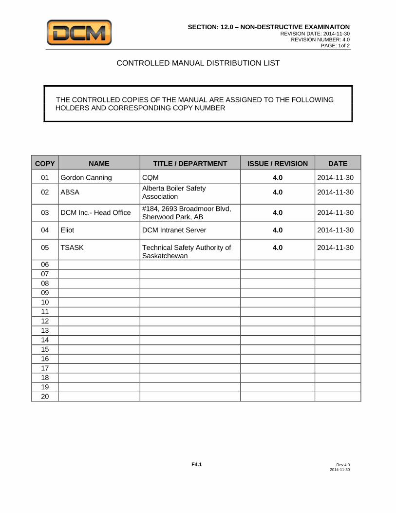
SECTION: 12.0 – NON-DESTRUCTIVE EXAMINAITON REVISION DATE: 2014-11-30
REVISION NUMBER: 4.0 PAGE: 1of 2
F4.1 Rev.4.0 2014-11-30
CONTROLLED MANUAL DISTRIBUTION LIST THE CONTROLLED COPIES OF THE MANUAL ARE ASSIGNED TO THE FOLLOWING
HOLDERS AND CORRESPONDING COPY NUMBER
COPY NAME TITLE / DEPARTMENT ISSUE / REVISION DATE
01 Gordon Canning CQM 4.0 2014-11-30
02 ABSA Alberta Boiler Safety Association 4.0 2014-11-30
03 DCM Inc.- Head Office #184, 2693 Broadmoor Blvd, Sherwood Park, AB 4.0 2014-11-30
04 Eliot DCM Intranet Server 4.0 2014-11-30
05 TSASK Technical Safety Authority of Saskatchewan
4.0 2014-11-30
06 07 08 09 10 11 12 13 14 15 16 17 18 19 20
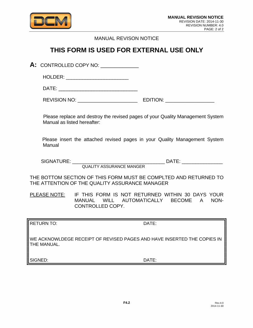
MANUAL REVISION NOTICE REVISION DATE: 2014-11-30
REVISION NUMBER: 4.0 PAGE: 2 of 2
F4.2 Rev.4.0 2014-11-30
MANUAL REVISON NOTICE
THIS FORM IS USED FOR EXTERNAL USE ONLY
A: CONTROLLED COPY NO: ______________ HOLDER: _______________________ DATE: _____________________________ REVISION NO: ______________________ EDITION: __________________ Please replace and destroy the revised pages of your Quality Management System
Manual as listed hereafter: Please insert the attached revised pages in your Quality Management System
Manual SIGNATURE: __________________________________ DATE: _______________ QUALITY ASSURANCE MANGER
THE BOTTOM SECTION OF THIS FORM MUST BE COMPLTED AND RETURNED TO THE ATTENTION OF THE QUALITY ASSURANCE MANAGER PLEASE NOTE: IF THIS FORM IS NOT RETURNED WITHIN 30 DAYS YOUR
MANUAL WILL AUTOMATICALLY BECOME A NON-CONTROLLED COPY.
RETURN TO: DATE: WE ACKNOWLDEGE RECEIPT OF REVISED PAGES AND HAVE INSERTED THE COPIES IN THE MANUAL. SIGNED: DATE:
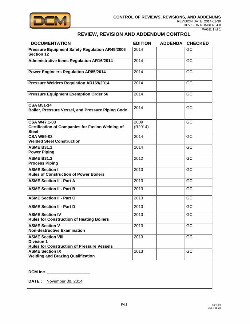
CONTROL OF REVIEWS, REVISIONS, AND ADDENUMS REVISION DATE: 2014-01-30
REVISION NUMBER: 4.0 PAGE: 1 of 1
F4.3 Rev.4.0 2014-11-30
REVIEW, REVISION AND ADDENDUM CONTROL
DOCUMENTATION EDITION ADDENDA CHECKED
Pressure Equipment Safety Regulation AR49/2006 Section 12
2014
GC
Administrative Items Regulation AR16/2014 2014 GC
Power Engineers Regulation AR85/2014 2014 GC
Pressure Welders Regulation AR169/2014 2014 GC
Pressure Equipment Exemption Order 56 2014 GC
CSA B51-14 Boiler, Pressure Vessel, and Pressure Piping Code 2014 GC
CSA W47.1-03 Certification of Companies for Fusion Welding of Steel
2009 (R2014)
GC
CSA W59-03 Welded Steel Construction
2014 GC
ASME B31.1 Power Piping
2014 GC
ASME B31.3 Process Piping
2012 GC
ASME Section I Rules of Construction of Power Boilers
2013 GC
ASME Section II - Part A 2013 GC
ASME Section II - Part B 2013 GC
ASME Section II - Part C 2013 GC
ASME Section II - Part D 2013 GC
ASME Section IV Rules for Construction of Heating Boilers
2013 GC
ASME Section V Non-destructive Examination
2013 GC
ASME Section VIII Division 1 Rules for Construction of Pressure Vessels
2013 GC
ASME Section IX Welding and Brazing Qualification
2013 GC
DCM Inc. ___________________ DATE : November 30, 2014