dcmt-2500 wireless transmitter - dakota alert
TRANSCRIPT

DCMT-2500WirelessTransmitterOwner’s Manual

2.
WarningsThis device complies with Part 15 of the FCC rules, Operation of this device is subject to the following conditions: 1. This device may not cause harmful interference. 2. This device must accept any interference, including interference that may cause undesired operation.
Installation:The DCMT-2500 transmitter is used with the Dakota Alert DCR-2500 receiver. The DCMT-2500 transmitter uses a passive infrared (PIR) detector to detect people, vehicles or large animals at the monitored location. When the transmitter detects an object, it will send a signal to the receiver, which will sound one of four different tones (Classical, Westminster Chime, Ding Dong, or Whistle) for a few seconds. The transmitter can be used as a driveway alarm, or in the back yard to monitor around tool sheds or patios.

3.
Operation: (Always test unitprior to installation)
1. Using a Phillips screwdriver, remove the screws (Figure 1, A-D) at each corner of the DCMT until the transmitter separates into two pieces.
2. Connect a 9-volt alkaline battery to the transmitter (Figure 2).
3. For maximum range between the transmitter and receiver, the transmitter should be mounted on a wooden post or tree (steel posts may cause interference with the radio signal). Although the maximum range is about a 1/2 mile, obstructions such as hills, trees, metal siding and stucco can reduce the range.
Figure 1
A B
C D
Figure 2
9-volt Battery
4.
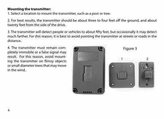
Mounting the transmitter:1. Select a location to mount the transmitter, such as a post or tree.
2. For best results, the transmitter should be about three to four feet off the ground, and about twenty feet from the side of the drive.
3. The transmitter will detect people or vehicles to about fifty feet, but occasionally it may detect much farther. For this reason, it is best to avoid pointing the transmitter at streets or roads in the distance.
4. The transmitter must remain com-pletely immobile or a false signal may result. For this reason, avoid mount-ing the transmitter on flimsy objects or small diameter trees that may move in the wind.
Figure 3
1 2
5.
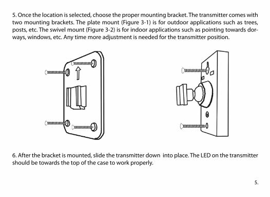
5. Once the location is selected, choose the proper mounting bracket. The transmitter comes with two mounting brackets. The plate mount (Figure 3-1) is for outdoor applications such as trees, posts, etc. The swivel mount (Figure 3-2) is for indoor applications such as pointing towards dor-ways, windows, etc. Any time more adjustment is needed for the transmitter position.
6. After the bracket is mounted, slide the transmitter down into place. The LED on the transmitter should be towards the top of the case to work properly.

6.
Mount the transmitter with the LED towards the top for proper installation.
LOW BATTERY ALERT: If the receiver sounds a second alert 30 seconds after the first alert, provided nothing activates the transmitter again, the 9-volt battery in the transmitter should be changed.
Correct Installation
LED
Incorrect Installation
LED
7.
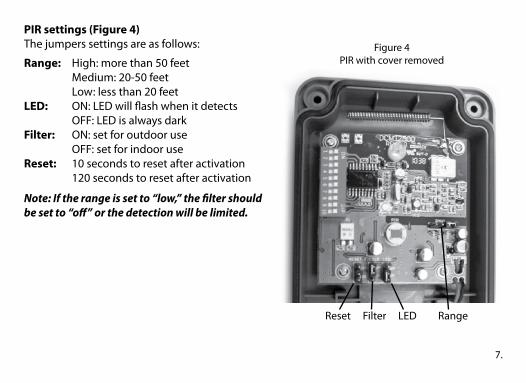
PIR settings (Figure 4)The jumpers settings are as follows:
Range: High: more than 50 feet Medium: 20-50 feet Low: less than 20 feetLED: ON: LED will flash when it detects OFF: LED is always darkFilter: ON: set for outdoor use OFF: set for indoor useReset: 10 seconds to reset after activation 120 seconds to reset after activation
Note: If the range is set to “low,” the filter should be set to “off” or the detection will be limited.
Reset Filter LED Range
Figure 4PIR with cover removed

8.
{{
43Figure 5
Coding the transmitter:Note: The transmitters and receivers are preset at the factory. DO NOT change settings, unless changing the tune or experiencing false signals.
1. Locate the dip switches in the DCMT-2500 circuit board (Figure 5).
2. The first eight dip switches are for the frequency setting (256 combinations). Set switches 1-8 (Figure 5-3) to match the eight switches in the receiver.
3. Switches 9 and 10 (Figure 5-4) are for the zone/channel settings on the transmitter. The four zones are listed in the table below.
LOW BATTERY ALERT: If the receiver sounds a second alert 30 seconds after the first alert, provided nothing activates the transmitter again, the 9-volt battery in the transmitter should be changed.
Switch 9 Switch 10 Channel Tune
On On 1 Classical
Off On 2 Westminster
On Off 3 Ding Dong
Off Off 4 Whistle
9.
Coding the receiver:1. Open the receiver case by inserting a small screwdriver into one of the pry notches on the side of the case. (refer to receiver manual)2. Gently lift off the front cover.3. Locate the eight dip switches on the receiver and make sure they are set identically to dip switches 1-8 on the transmitter.
Note: If more than one transmitter is used with the receiver, the first eight dip switches of all transmitters must match the eight dip switches of the receiver.
Note: Whenever a change is made to the time jumper or the dip switches, the receiver must be turned OFF and then back ON to operate properly.
Frequency: 433.92 MHzOperating range: -30˚F to 110˚FBattery life: 6-12 months
10.
Troubleshooting the DCMT-2500
Although the DCMT-2500 should be very reliable, there are occasions when you might have false alarms or a failure to alert. If you are getting false alarms, please try this: •Setfilterjumperto“ON”. •Decreaserangejumper. •Makesurethatthetransmitterisnotpointingataroadinthedistance. •Thesunmaybecausingfalsesignals;trytorelocatethetransmittertoadifferentposition. •Makesurethetransmitterisnotdetectinganimals.
If the transmitter is not detecting, try one of these: •Changethebatteryinthetransmitter. •Makesurethetransmitterandreceiverarecodedalike. •Changetheheightanddistanceofthetransmitterfromthedriveway. •Movethetransmitterclosertothereceiver. •Keepthetransmitterawayfromlargemetalobjectsthatmayinterferewiththeradiosignal.

11.
TECHNICAL SUPPORTIf you encounter any difficulty in the operation of this product after reading the manual, please contact us. You can reach us by phone at 605-356-2772 from 8:30 AM to 5:00 PM Monday through Friday (Central Standard Time). We will be happy to answer your questions and help you in any way we can.
WARRANTYDakota Alert warrants this product to be free of defects in material and workmanship for a period of one year from the date of purchase. This warranty does not cover damage resulting from ac-cident, abuse, act of God or improper operation.If this product does become defective, simply return it to Dakota Alert. Please include a note describing the troubles along with your name and return address as well as the original sales receipt. If the product is covered under warranty it will be repaired or replaced at no charge. If it is not covered by warranty, you will be notified of any charges before work is done.

Dakota Alert, Inc.32556 E. Main Street phone: (605) 356-2772P0 Box 130 fax: (605) 356-3662Elk Point, SD 57025 web: www.dakotaalert.com