dcpp form 69-21593 (04/09/12) cf3.id4 attachment 4 design … · margin data recorded using srm...
TRANSCRIPT

DCPP Form 69-21593 (04/09/12) CF3.ID4 Attachment 4Page 1 of 3
Design Calculation Summary
DCPP Form 69-21593.doc 0808.1351
Block 1: Cover Sheet
Unit(s): 1&2 Legacy No. IS-022D SAP Calculation No.: 9000041947 Type: IS
System No. 36 Responsible Group: EDC/SEQ Quality Classification: Q
System, Structure, or Component: Process Protection System Racks
File No.: 21.10 Binder No: N/A Index No: N/A
Subject: PPS Seismic Qualification
Computer/Electronic Calculation: YES NO
Computer ID Application Name and Version
Date of Latest Installation/Validation
Test
S&L PC ZL8301 SAP2000, Version 14.1 07-17-2014
S&L PC ZL8591 RSG, Version 2.0 07-31-2013
Working Copy Calculation Page Index
Calculation Package Contains Pages No. of Pages
Cover Sheet CF3.ID4 Attachment 4, Page 1 1
Signature Sheet CF3.ID4 Attachment 4, Page 2 1
Calculation Checklist CF3.ID4 Attachment 4, Page 3 1
Calculation Body Page 4 - 30 27
Attachments Page A1 - AD4 52010
Other:
TOTAL 52040

DCPP Form 69-21593 (04/09/12) Design Calculation Summary
Block 2: Signature Sheet
CF3.ID4 Attachment 4 Page 2 of 3
SAP Cale No. 9000041947 Legacy No. _r_s_-_o 2_2_n ______ _
Part NoNersion No 000/00
Status 0 Final D Superseded D Void D Cancelled D History
Pages Affected All
Requesting Doc No. PLO 68001801 I Notification 50405932
LBIE AD/Screen ['.g!Yes 0No D N/A
LBIE Eval 0Yes ['.g!No D N/A
Check method* 0 A = Detailed Check J D B = Alternate Method JD C = Critical Point Check
PSRC Meeting No N/A
PSRC Meeting Date N/A
Prepared By: f. (~ / 'TO"-> 'f K ( N\ IN/A Date: tlB - o t> - 2-o( lo Signature LAN ID
Date: 8/8 /lk, # I
Date:
/ • ~Si nature
Supervisor: __ +//,,._---..... ~·~ IJ __ __,,__,'~,._,/"""l't"iH~r--:----=~~' =N~/A~--('1"" ~ gnJfr? C;T6;;;= LAN ID
Owner's Acceptance
per CF3.ID17 : -----------------''-------- Date: ------Signature LAN ID
A. Insert PE stamp or seal below B. Insert stamp directing to PE stamp or seal
DCPP Form 69-21593.doc 0808.1351

DCPP Form 69-21593 (04/09/12) Design Calculation Summary
Block 3: Checklist
Item to Verify
SAP Entry: Cale number, part number, version number, legacy number, superior document or Reason for calc field on add I data tab
Cale Cover Sheet: All applicable field entries complete, computer/application/validation information filled in for computer calculations and working copy calculation page index completed
Signature Sheet: Part number, version number, revised pages and reason for revision clearly identified
Calculation Body
Purpose is clear and includes originating document (step 5.3.2a)
Background is established clearly (step 5.3.2b)
Assumptions are validated or clearly indicated Preliminary if verification is required. SAPN number z0'6 ~ ('=> 73 (step 5.3.2c)
Inputs are validated or clearly indicated Preliminary if verification is required. SAPN number. (step 5.3.2d)
As-Built Configuration is verified, as required (step 5.3.2d. 7 and 5.3.2d.10)
Methodology described is concise and clear (step 5 3.2e)
Acceptance Criteria is clear - developed from design and licensing basis, verified against safety analysis criteria and methodology is consistent with licensing basis (step 5.3 2f)
Body of the Calculation is clear regarding analysis and logic for anyone without going back to the author (step 5.3.2g)
Results: Provides a precise solution to the stated purpose and provides justification to prepare LBIE for the package (step 5.3.2h)
Margin assessment includes quantitative or qualitative assessment on existing margin (step 5.3.2i)
Margin data recorded using SRM module (step 5.3.2i.4)
Conclusion includes applicability and limitations (step 5.3.2j)
Impact on other documents determined (step 5.3.2k)
References: Non-retrievable references attached (step 5.3.21.1)
• Linked input, linked output and unlinked other references identified . . Linked references entered on the object links tab (step 5.3.21.2 and 5 3 21.3)
Attachments for reference only are clearly identified (step 5.3.2m.6)
All revised pages have the correct calc number, part number, version number (9*xxxxx-yyy-zz) and legacy number (step 5.2.2e)
DCPP Form 69-21593.doc 0808.1351
CF3.ID4 Attachment 4 Page 3 of 3
Complete (enter N/A if not applicable)
Preparer Checker
LANID
N/A
N/A
N/A
N/A
N/A
N/A
N/A
N/A
N/A
N/A
N/A
N/A
N/A
N/A
N/A
N/A
N/A
N/A
N/A
Initials LAN ID Initials
\'?-N/A Jwl N/A v; \~
\\L N/A rJtvf
1¥- N/A 'J-wj-\ 'l. N/A ~J
v
T'?-N/A ff
'"-N/A JN;
T~ N/A Jwj \. \<'.- N/A ~j
v v N/A
T~ ~I \~
N/A
~rt \~
N/A
JwrJ -r "- N/A
~t f-.:J{A N/A tJ/14 \'?- N/A ;Jwj. I 't- N/A jWJ
N/A
Pl \'?.-
tJ (A N/A tJ/A N/A rfwrJ \IL-
SAP No. 9000041947 Part No. 000 I Version No. 00
Legacy No. JS-0220

TABLE OF CONTENTS SECTION PAGES DCPP Form 69-21593 1 – 3 TABLE OF CONTENTS 4 – 5 1 PURPOSE 6 – 7 2 ASSUMPTIONS 8 3 DESIGN INPUT 9 – 10 4 METHODOLOGY 11 – 12 5 CALCULATIONS 13 – 23 6 CONCLUSIONS 24 – 25 7 REFERENCES 26 – 30 ATTACHMENTS A Development of Response Spectra Consistent Time Histories for Process Protection System Cabinets A1 – A112
B DIT-50831673-001 (dated 2016-06-22) (Ref. 3) B1 – B81 C DIT-50831673-002 (dated 2016-06-13) (Ref. 11) C1 – C9 D Walkdown of DCPP PPS and PCS Cabinets (Walkdown Report dated 2016-03-01) (Ref. 2) D1 – D44
E SAP2000 Model Input Data (Overall Dimensions and Component Masses) E1 – E22
F Empty Cabinet Model [Empty Cabinet (06-17-2016).SDB] F1 – F68 G ALS Cabinet Model [ALS Cabinet (06-17-2016).SDB] G1 – G101 H HMI Cabinet Model [HMI Cabinet (06-17-2016).SDB] H1 – H100 I Tricon Cabinet Model [Tricon Cabinet (06-17-2016.SDB)] I1 – I106 J Modification Sketches J1 – J26 K PPS Sets I and II – 5-Bay Cabinet Lineup Model [PPS Set I (06-02-2016)_fix 7.SDB]
K1 – K8929
L Unit 1 PPS Set III / PCS Group 3 – 6-Bay Cabinet Lineup Model [PPS Set III (06-01-2016_fix 10.SDB)]
L1 – L10907
M Unit 2 PPS Set III / PCS Group 3 – 6-Bay Cabinet Lineup Model [PPS Set III (06-01-2016_fix 11.SDB)]
M1 – M10254
N PPS Set IV / PCS Group 4 – 8-Bay Cabinet Lineup Model [PPS Set IV (06-01-2016)_fix 2.SDB]
N1 – N14225
O Model Nodes for IERS Generation O1 – O14 P Connection Walkdown Report (dated 2016-06-22) (Ref. 47) P1 – P17 Q AMCO Drawings Q1 – Q7 R IERS Plots R1 – R473 S Member and Connection Evaluations S1 – S6021 T Member Time-History Evaluation Script and Validation T1 – T20 U Connection Time-History Evaluation Script and Validation U1 – U37 V Component Qualifications V1 – V82 W Miscellaneous Component Evaluations W1 – W18 X Time Stamp of Electronic Files X1 – X18
Pacific Gas and Electric Company Diablo Canyon Power Plant Units 1 & 2
SAP No. 9000041947 Part No. 000 / Version No. 00
Legacy No. IS-022D Page 4 of 30
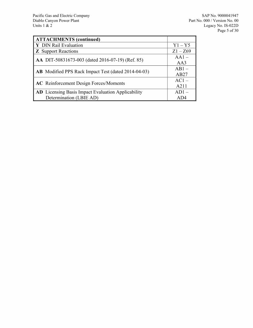
ATTACHMENTS (continued) Y DIN Rail Evaluation Y1 – Y5 Z Support Reactions Z1 – Z69
AA DIT-50831673-003 (dated 2016-07-19) (Ref. 85) AA1 – AA3
AB Modified PPS Rack Impact Test (dated 2014-04-03) AB1 – AB27
AC Reinforcement Design Forces/Moments AC1 – A211
AD Licensing Basis Impact Evaluation Applicability Determination (LBIE AD)
AD1 – AD4
Pacific Gas and Electric Company Diablo Canyon Power Plant Units 1 & 2
SAP No. 9000041947 Part No. 000 / Version No. 00
Legacy No. IS-022D Page 5 of 30

1 PURPOSE 1.1 BACKGROUND The Diablo Canyon Power Plant (DCPP) Process Protection System (PPS) is a Safety-Related Class 1A (PG&E Design Class 1, DCPP Class Q, Electrical Class 1E) I&C System which receives various Safety-Related plant parameters, provides parameter control room indication signals, compares parameters against set points, and provides signals to the Solid State Protection System (SSPS) if the set points are exceeded. The PPS Replacement Project replaces the existing Westinghouse Eagle 21 signal conditioning, control, and personnel interface electronics with a new PPS consisting of a combination of Safety-Related Invensys Triconex and Westinghouse Advanced Logic System (ALS) components. To facilitate this replacement, the existing Westinghouse Eagle 21 components will be removed from each existing electrical panel and the new Triconex/ALS components will be installed within the existing electrical panels. The PPS cabinets consist of a structural framing system which supports various safety-related and nonsafety-related I&C components. These cabinets are located in the Cable Spreading Room, which is located in the Auxiliary Building (AB) EL. 128’. As the PPS is classified as Design Class 1, the PPS cabinets shall be qualified for applicable Design Class 1 loading conditions as delineated in the FSAR Update (Ref. 16), Section 3.2.2.4.1 (Seismic Classifications). License Amendment Request (LAR) 11-07 (Ref. 1) has been submitted to the Nuclear Regulatory Commission (NRC) for this modification. This calculation is being issued in support of the NRC requests for information on the LAR [see PG&E Letter DCL-14-036 (Ref. 22)]. See additional background information for the PPS cabinets in the FSAR Update (Ref. 16), Section 3.10.2.1.3. See also IS-022 (Ref. 12) and IS-022A (Ref. 13) for previous calculations performed for the PPS. 1.2 PURPOSE The purpose of this calculation is to evaluate the new PPS cabinet configurations for design basis load conditions. This includes evaluation of the structural adequacy of the existing cabinets and the new rack support system, and the seismic qualification of the new PPS components. The applicable load conditions include Design Earthquake (DE), Double Design Earthquake (DDE), and Hosgri Earthquake (HE) loads. 1.3 SCOPE 1. Perform seismic analysis of the new cabinet configurations under DE, DDE, and HE conditions using finite element methods. Determine responses [e.g., In-Equipment Response Spectra (IERS) and stresses] from the design basis load combinations. 2. Compare the computed required IERS against the Test Response Spectra (TRS) (provided by the testing facilities) for Safety-Related components within the cabinets.
Pacific Gas and Electric Company Diablo Canyon Power Plant Units 1 & 2
SAP No. 9000041947 Part No. 000 / Version No. 00
Legacy No. IS-022D Page 6 of 30
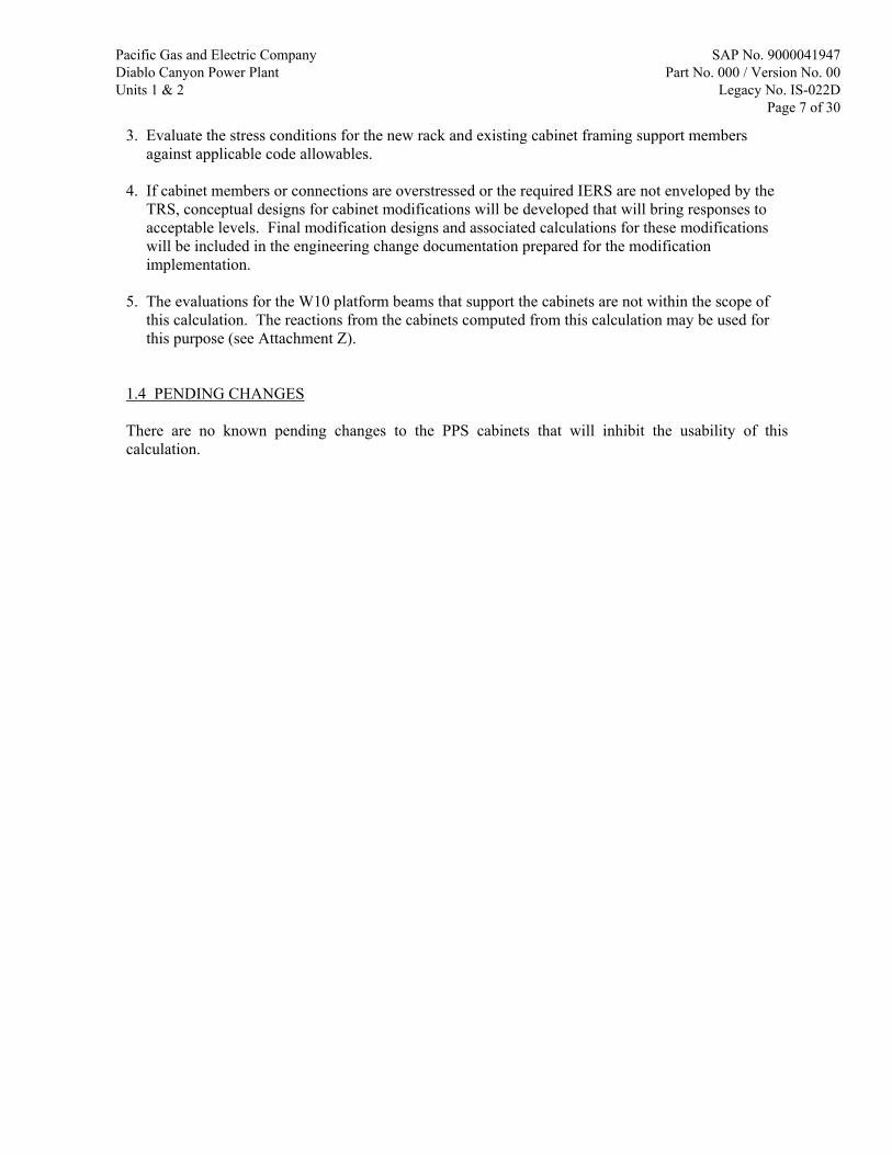
3. Evaluate the stress conditions for the new rack and existing cabinet framing support members against applicable code allowables. 4. If cabinet members or connections are overstressed or the required IERS are not enveloped by the TRS, conceptual designs for cabinet modifications will be developed that will bring responses to acceptable levels. Final modification designs and associated calculations for these modifications will be included in the engineering change documentation prepared for the modification implementation. 5. The evaluations for the W10 platform beams that support the cabinets are not within the scope of this calculation. The reactions from the cabinets computed from this calculation may be used for this purpose (see Attachment Z). 1.4 PENDING CHANGES There are no known pending changes to the PPS cabinets that will inhibit the usability of this calculation.
Pacific Gas and Electric Company Diablo Canyon Power Plant Units 1 & 2
SAP No. 9000041947 Part No. 000 / Version No. 00
Legacy No. IS-022D Page 7 of 30

2 ASSUMPTIONS 2.1 UNVERIFIED ASSUMPTIONS 1. DIT-50831673-001 (Ref. 3) is UNVERIFIED. It provides the drawings for the new rack configurations. DCPP SAP Notification 50831673-Task 1 was initiated to track the verification of this DIT. The input used for this calculation is preliminary and will be used for “information only”. 2. DIT-50831673-002 (Ref. 11) is UNVERIFIED. It provides the weights of the new components. DCPP SAP Notification 50831673-Task 3 was initiated to track the verification of this DIT. The input used for this calculation is preliminary and will be used for “information only”. 3. The PPS rack assembly drawings provided in DIT-50831673-001 (Ref. 3) is for Unit 1. It is assumed that the Unit 2 PPS rack assemblies are the same as Unit 1. DCPP SAP Notification 50831673-Task 6 was initiated to track the verification of this assumption. The input used for this calculation is preliminary and will be used for “information only”. 4. It is assumed that the existing Eagle 21 cabinet frame connections are the same as the current AMCO drawings (Attachment Q) with the same part number. DCPP SAP Notification 50831673-Task 6 was initiated to track the verification of this assumption. The input used for this calculation is preliminary and will be used for “information only”. 2.2 OTHER ASSUMPTIONS Any minor assumptions (e.g., engineering judgment), if used, are justified in the body of the calculation.
Pacific Gas and Electric Company Diablo Canyon Power Plant Units 1 & 2
SAP No. 9000041947 Part No. 000 / Version No. 00
Legacy No. IS-022D Page 8 of 30
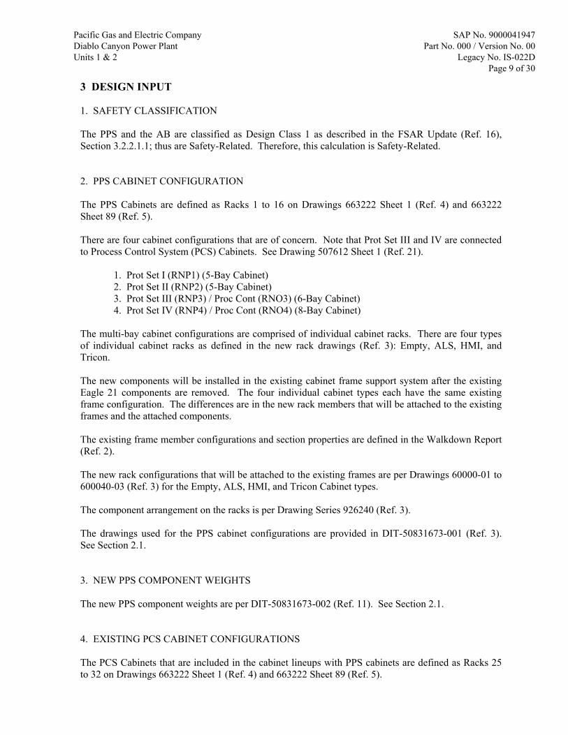
3 DESIGN INPUT 1. SAFETY CLASSIFICATION The PPS and the AB are classified as Design Class 1 as described in the FSAR Update (Ref. 16), Section 3.2.2.1.1; thus are Safety-Related. Therefore, this calculation is Safety-Related. 2. PPS CABINET CONFIGURATION The PPS Cabinets are defined as Racks 1 to 16 on Drawings 663222 Sheet 1 (Ref. 4) and 663222 Sheet 89 (Ref. 5). There are four cabinet configurations that are of concern. Note that Prot Set III and IV are connected to Process Control System (PCS) Cabinets. See Drawing 507612 Sheet 1 (Ref. 21). 1. Prot Set I (RNP1) (5-Bay Cabinet) 2. Prot Set II (RNP2) (5-Bay Cabinet) 3. Prot Set III (RNP3) / Proc Cont (RNO3) (6-Bay Cabinet) 4. Prot Set IV (RNP4) / Proc Cont (RNO4) (8-Bay Cabinet) The multi-bay cabinet configurations are comprised of individual cabinet racks. There are four types of individual cabinet racks as defined in the new rack drawings (Ref. 3): Empty, ALS, HMI, and Tricon. The new components will be installed in the existing cabinet frame support system after the existing Eagle 21 components are removed. The four individual cabinet types each have the same existing frame configuration. The differences are in the new rack members that will be attached to the existing frames and the attached components. The existing frame member configurations and section properties are defined in the Walkdown Report (Ref. 2). The new rack configurations that will be attached to the existing frames are per Drawings 60000-01 to 600040-03 (Ref. 3) for the Empty, ALS, HMI, and Tricon Cabinet types. The component arrangement on the racks is per Drawing Series 926240 (Ref. 3). The drawings used for the PPS cabinet configurations are provided in DIT-50831673-001 (Ref. 3). See Section 2.1. 3. NEW PPS COMPONENT WEIGHTS The new PPS component weights are per DIT-50831673-002 (Ref. 11). See Section 2.1. 4. EXISTING PCS CABINET CONFIGURATIONS The PCS Cabinets that are included in the cabinet lineups with PPS cabinets are defined as Racks 25 to 32 on Drawings 663222 Sheet 1 (Ref. 4) and 663222 Sheet 89 (Ref. 5).
Pacific Gas and Electric Company Diablo Canyon Power Plant Units 1 & 2
SAP No. 9000041947 Part No. 000 / Version No. 00
Legacy No. IS-022D Page 9 of 30

The existing frame member configurations and section properties are defined in the Walkdown Report (Ref. 2). The PCS rack assemblies are nearly identical to the new PPS rack assemblies per the Walkdown Report (Ref. 2). The component arrangement on the racks is per Drawing 663222 Sheets 26 – 33 (Refs. 30 – 37) for Unit 1 and Drawing 663222 Sheets 114 – 121 (Refs. 38 – 45) for Unit 2. 5. DESIGN BASIS SEISMIC EVENTS The inputs required to develop the acceleration time-histories for the design basis seismic floor motion (DE, DDE, and HE) are provided in Attachment A. Damping Values for the Time-History Analyses For the time history analysis of the cabinets, structural damping for DE, DDE, and Hosgri are 2%, 2%, and 7% of critical damping, respectively. These values are obtained from the DCPP FSAR Update (Ref. 16), Section 3.7.1.4 for “Bolted or riveted steel assemblies”. Although there are a few welds in the PPS cabinet structural system, the overwhelming majority of the connections are bolted, including the critical connections that transfer most of the seismic load. In-Equipment Response Spectra (IERS) Broadening DCM T-6 (Ref. 26), Table 4.3-6 provides criteria for response spectra broadening (widening) for the Auxiliary Building. It states that for the DE, DDE, and Hosgri, the spectra are broadened +/-10%, +/-10%, and, +5% & -15%, respectively. When generating the required IERS for component qualification, the peaks will be widened in accordance with DCM T-6, unless noted otherwise. 6. MEMBER AND CONNECTION STRESS ACCEPTANCE CRITERIA In general, the acceptance criteria for member and connection stresses are based on the allowable stresses provided in Calculation SQME-77 (Ref. 29). If criteria for certain limit states are not provided in Calculation SQME-77 (Ref. 29), the requirements of the AISC 7th Edition (Ref. 28) or AISI 1968 (Ref. 27) code will be used for the evaluations. Note that the codes of record for DCPP for hot-rolled and cold-formed steel are the AISC 7th Edition and AISI 1968 code, respectively. This is consistent with DCM T-10 (Ref. 25) and the FSAR Update (Ref. 16). A summary of the acceptance criteria is provided in Attachment S, Section 2.1.
Pacific Gas and Electric Company Diablo Canyon Power Plant Units 1 & 2
SAP No. 9000041947 Part No. 000 / Version No. 00
Legacy No. IS-022D Page 10 of 30

4 METHODOLOGY 4.1 METHODOLOGY FOR DESIGN/ANALYSIS The eight cabinet sets in question (PPS Set I to IV for Units 1 & 2), which are located on the Cable Spreading Room floor (Auxiliary Building EL. 128’), will be evaluated for the design basis seismic conditions (DE, DDE, and HE). The existing framing and new rack members will be qualified by analysis and the internal components will be qualified by seismic testing (documented in the seismic test reports). The design basis load combinations are: 1. DL + DE 2. DL + DDE 3. DL + HE Note that there are no applicable operating loads. 3-Dimensional structural frame-element models will be created using SAP2000 software. The models will account for the existing frame configurations, new rack configurations, and the new component masses that make up the cabinet assemblies. Note that the individual PPS cabinets will be used to represent the existing PCS cabinets due to their similarities. The boundary of the models will be where the cabinet base is anchored to the structural steel W10 beams, which are a part of the Structural Conduit Platform [see Drawing 6003029 (Ref. 20) and Drawing 59658 (Ref. 17)]. The cabinet base channels are welded along the center of the W10 flange right above the beam web. The Structural Conduit Platform is essentially a grid system as shown on Drawing 59658 (Ref. 17). The W10 members are anchored to the slab below (EL. 128’ floor) with post-installed expansion anchors spaced at 12” o.c., staggered. For these reasons, it is considered that the W10 members are rigid and will not contribute to the panel flexibility; therefore, they will not be included in the model. The cabinets are essentially a cantilever supported at the base, with the existing cabinet structure behaving as a moment frame. Linear static analysis will be performed for the DL case. To account for the seismic excitation of the floor, acceleration time-histories consistent with the design basis response spectra for the Auxiliary Building at EL. 127’-4” floor will be generated to be used for time-history analyses in SAP2000. Time-histories for the NS, EW, and vertical directions will be generated for the three earthquakes in question. See Attachment A for a detailed description of the time-history generation methodology. The three components of each earthquake (NS, EW, and vertical) will be applied simultaneously in a single analysis. This approach is recognized in Regulatory Guide 1.92 (Ref. 24) provided that the three components of earthquake are statistically independent (this has been verified and is documented in Attachment A). Linear modal time-history analysis will be performed for each of the three design earthquakes. To account for the residual rigid response due to the mass not captured by the eigenvector solution, the program will compute a static correction mode (or missing mass mode) for this purpose. To qualify the safety-related components in the cabinets, IERS will be generated in SAP2000 using the results of the time-history analyses at specific locations. This will then be compared against TRS,
Pacific Gas and Electric Company Diablo Canyon Power Plant Units 1 & 2
SAP No. 9000041947 Part No. 000 / Version No. 00
Legacy No. IS-022D Page 11 of 30

which are provided in the seismic test reports. The components are considered to be acceptable if the IERS [including +10% margin per IEEE-323 (Ref. 23)] is enveloped by the TRS. To evaluate the stress conditions of the existing cabinet frame and new rack members, the results of the DL and seismic load cases will be combined using algebraic summation. The stresses will be evaluated against the requirements of Calculation SQME-77 (Ref. 29), AISC 7th Edition (Ref. 28) and/or AISI 1968 code (Ref. 27) (See Section 3, Item 6). If the cabinet members are overstressed or the required IERS are not enveloped by the TRS, reinforcements for the cabinets will be designed to bring responses to acceptable levels. The methodology of designing the reinforcements will be provided in the body of the calculation. 4.2 COMPUTER PROGRAMS The following programs used in the preparation of this calculation are verified and validated as a part of the Sargent & Lundy (S&L) QA Program: 1. SAP2000 Version 14.1 (SAP2000) Computers and Structures, Inc. S&L PC No. ZL8301 Controlled File Summary - SAP2000 (S&L Program No. 03.7.224-14.1) Type: 2 Status: O Effective Date: 07-17-2014 Controlled File Path: \\SNLVS5\SYS3\OPS$\SAP224141\
2. Response Spectrum Generator (RSG) Version 2.0 Sargent & Lundy LLC S&L PC No. ZL8591
Controlled File Detail - RSG (S&L Program No. 03.7.414-2.0) Type: 3 Status: L Effective Date: 07-31-2013 Controlled File Path: \\SNLVS5\SYS3\OPS$\RSG41420\ 3. Mathcad 14 (MATHCAD) Parametric Technology Corporation Version 14.0 M035 S&L PC Nos. ZL10467, ZL8591, and ZL8301 Controlled File Detail - MATHCAD (S&L Program No. 03.7.548-1435) Type: 2 Status: O Effective Date: 11-22-2013 Controlled File Path: C:\Program Files (x86)\Mathcad\Mathcad 14\ Note that any open error notices were searched for applicability. None were found.
Pacific Gas and Electric Company Diablo Canyon Power Plant Units 1 & 2
SAP No. 9000041947 Part No. 000 / Version No. 00
Legacy No. IS-022D Page 12 of 30

5 CALCULATIONS 5.1 ANALYSIS MODEL GENERATION 5.1.1 MODELING CONSIDERATIONS FOR INDIVIDUAL CABINETS The PPS cabinet assemblies (PPS Sets I to IV) are comprised of individual cabinets that are attached to each other. Each cabinet is given a rack number as defined on Drawings 663222 Sheet 1 (Ref. 4) and 663222 Sheet 89 (Ref. 5). The PPS cabinets are identified as Racks 1 to 16 and the PCS cabinets of concern are identified as Racks 25 to 32. There are four types of individual PPS cabinets: Empty, ALS, HMI, and Tricon. The cabinets consist of existing frame members and new rack members. Each of the cabinets has the same existing frame configuration. The differences are in the new rack members that will be attached to the existing frames and the attached components. See Drawing 60000-01 Sheet 1 of 7 (Ref. 3) for the cabinet type for each PPS rack, Drawing 60000-01 Sheet 7 of 7 (Ref. 3) for a figure of the assembled cabinet types without the installed components, and Drawing 60000-01 Sheet 6 of 7 for the installed components. A SAP2000 model for each of the four individual types is created and input data is provided in Attachments F to I. To validate the initial SAP2000 model, a modal analysis was run for the Empty cabinet configuration and compared to the results of ping tests performed in 2014 on the existing cabinets (see Attachment AB). The first fundamental frequencies in the side-to-side and front-to-back directions from the modal analysis were found to be within 5% of the same frequencies from the ping test. Therefore, the model was considered to be validated. However, subsequent to the initial modeling, it was found that responses were too high (IERS > TRS) and modifications were required to bring responses down to acceptable levels. Thus, the current models no longer correlate to the ping test results. The existing frame member configurations and section properties are per the Walkdown Report (Ref. 2). As noted in the Walkdown Report, some configurations could not be verified against the plant design drawings due to lack of visibility, but judgments were provided based on what was verified against the drawings. The new rack configurations that will be attached to the existing frames are per Drawings 60000-01 to 60040-03 (Ref. 3) for all the individual cabinet types (Empty, ALS, HMI, and Tricon). The component arrangement on the racks is per Drawings 926240-1, -3, -4, -6, -8, -9, and -11 to -16 (Ref. 3). The arrangement provided on Drawings 926240-1, 926240-3, and 926240-4 are used to represent the typical configuration in the SAP2000 models for the ALS, HMI, and Tricon cabinet types, respectively. The component weights are per DIT-50831673-002 (Ref. 11). Note the following:
1. A cable weight of 80 lbs was provided for the ALS cabinets, but no cable weight was provided for the HMI or Tricon cabinets. The same cable weight is considered for the HMI and Tricon cabinets. To account for any cable weight that may be added, the 80-lb weight is increased to 100 lbs.
2. Actual cable weight distribution is unknown. This weight is considered to be distributed uniformly along several major support members.
3. Since the weights of some of the components are unknown, an additional 5% of the total weight is added to account for these weights. This additional weight is distributed uniformly along several major support members.
Pacific Gas and Electric Company Diablo Canyon Power Plant Units 1 & 2
SAP No. 9000041947 Part No. 000 / Version No. 00
Legacy No. IS-022D Page 13 of 30

The frame-element models in SAP2000 consist of the existing frame members and the new rack members. The components are accounted for by applying joint or uniform frame masses. The support joints are modeled where the cabinet base is anchored to the IP W10 beams that are part of the Structural Conduit Platform [see Drawing 6003029 (Ref. 20) and Drawing 59658 (Ref. 17)]. The global coordinate system used in SAP2000 is as follows: X = North – South Y = East – West Z = Up – Down Attachment E provides the cabinet dimensions, component masses, and additional masses for miscellaneous rack members not explicitly modeled in the SAP2000 individual cabinet models. The DIN Rail members (that support various components) that attaches to the P3300s (rear end of the cabinets) are not modeled. The reactions from the DIN Rail members are applied to the P3300s. These members are rigid (no local amplification) per Attachment Y (DIN Rail Evaluation); therefore considering only the tributary mass onto the P3300s is acceptable. Material Properties All of the existing cabinet framing members and new rack members that are modeled are steel. Therefore, the following properties are used for the material property definitions. Weight density = 0.284 lb/in3 Mass density = 7.35 x 10⁻⁴ (lb – s2/in)/in3 Modulus of elasticity = 29,000,000 psi Shear modulus = 11,153,846 psi Poisson’s ratio = 0.3
Pacific Gas and Electric Company Diablo Canyon Power Plant Units 1 & 2
SAP No. 9000041947 Part No. 000 / Version No. 00
Legacy No. IS-022D Page 14 of 30

5.1.2 MODELING CONSIDERATIONS FOR CABINET LINEUPS There are eight cabinet lineup sets that are under consideration. They are identified on Drawings 507612 Sheet 1 (Ref. 21), 663222 Sheet 1 (Ref. 4), and 663222 Sheet 89 (Ref. 5). 1. Unit 1 PPS Set I (5-Bay Cabinet) 2. Unit 1 PPS Set II (5-Bay Cabinet) 3. Unit 1 PPS Set III / PCS Group 3 (6-Bay Cabinet) 4. Unit 1 PPS Set IV / PCS Group 4 (8-Bay Cabinet) 5. Unit 2 PPS Set I (5-Bay Cabinet) 6. Unit 2 PPS Set II (5-Bay Cabinet) 7. Unit 2 PPS Set III / PCS Group 3 (6-Bay Cabinet) 8. Unit 2 PPS Set IV / PCS Group 4 (8-Bay Cabinet) The cabinet sets for Unit 1 are modeled in SAP2000. The existing cabinet framing, new racks, and new components for Units 1 and 2 individual cabinets (Empty, ALS, HMI, and Tricon) are considered to be the same. See Section 2.1, Item 3. Also, the cabinet sets with PPS Sets III and IV are also attached to PCS cabinets; thus the PCS cabinets are modeled as well. The individual PPS cabinet models are used to represent the PCS cabinets due to their similarities. It is known that the same existing cabinet frame construction was used for the PPS and PCS cabinets [see Walkdown Report (Ref. 2)]. By reviewing the applicable PCS component arrangement drawings [Drawing 663222 Sheets 26 – 33 (Refs. 30 – 37) for Unit 1 and Drawing 663222 Sheets 114 – 121 (Refs. 38 – 45) for Unit 2], it is concluded that the PCS and PPS cabinets are similar and any differences are judged to have an insignificant impact on the global seismic behavior of the cabinet lineup assemblies. The equivalent individual PPS cabinet models that are used to represent the PCS cabinets are shown below.
Cabinet Set No. PCS Rack No. Equivalent PPS Cabinet Type
PPS Set III / PCS Group 3
25 HMI 26 Tricon 27 Tricon
PPS Set IV / PCS Group 4
28 Tricon 29 Tricon 30 HMI 31 Tricon (with second story chassis removed) 32 Empty
Note that the arrangement of the individual cabinets in the cabinet lineups for Unit 1 and 2 are slightly different. The differences are judged to be insignificant as it will not adversely affect the overall stiffness and dynamic behavior of the cabinet sets. Therefore, the use of Unit 1 cabinet lineup sets in the SAP2000 models using the individual PPS cabinet models to represent the PPS and PCS cabinets is considered to be acceptable. In general, the individual cabinet models are imported into the cabinet lineup models and tied together using constraints. The cabinets are bolted to each other as shown on Drawings 663222 Sheet 1 (Ref.
Pacific Gas and Electric Company Diablo Canyon Power Plant Units 1 & 2
SAP No. 9000041947 Part No. 000 / Version No. 00
Legacy No. IS-022D Page 15 of 30
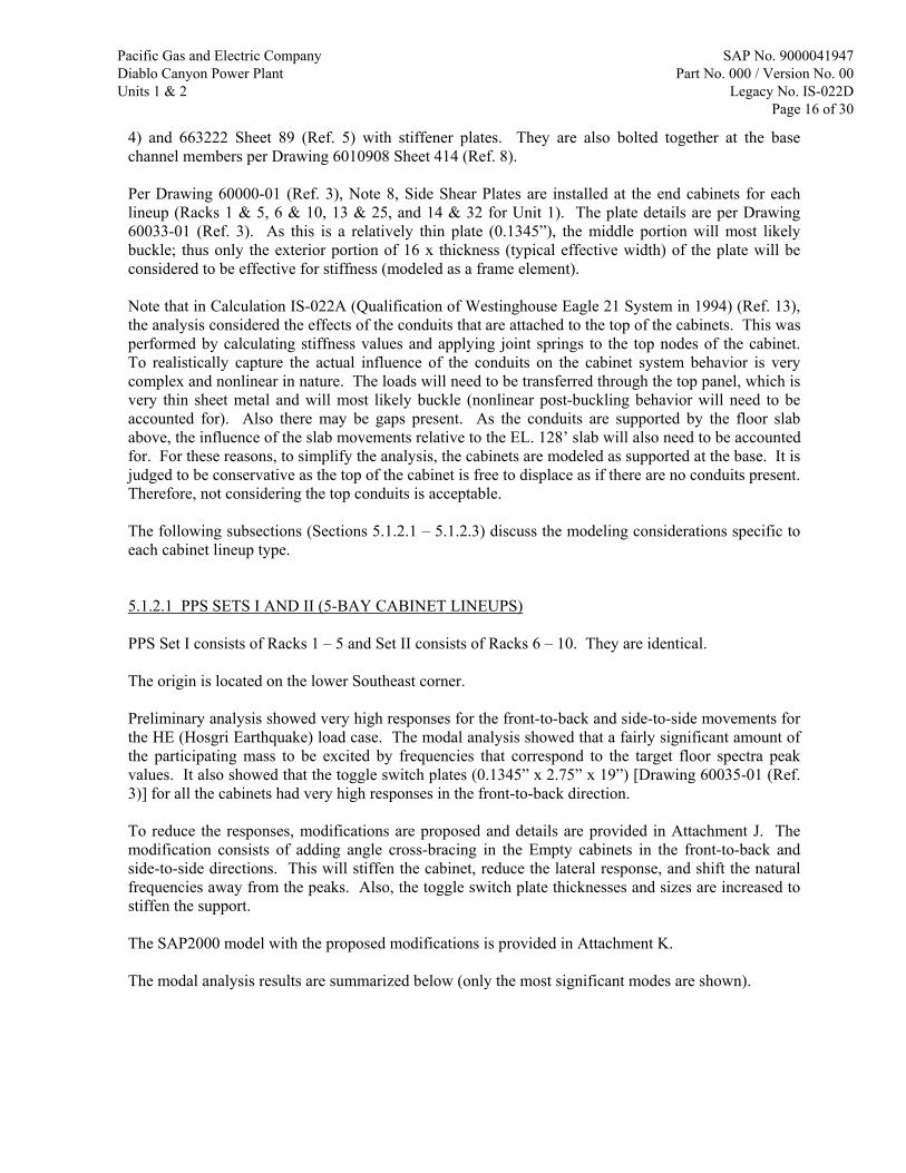
4) and 663222 Sheet 89 (Ref. 5) with stiffener plates. They are also bolted together at the base channel members per Drawing 6010908 Sheet 414 (Ref. 8). Per Drawing 60000-01 (Ref. 3), Note 8, Side Shear Plates are installed at the end cabinets for each lineup (Racks 1 & 5, 6 & 10, 13 & 25, and 14 & 32 for Unit 1). The plate details are per Drawing 60033-01 (Ref. 3). As this is a relatively thin plate (0.1345”), the middle portion will most likely buckle; thus only the exterior portion of 16 x thickness (typical effective width) of the plate will be considered to be effective for stiffness (modeled as a frame element). Note that in Calculation IS-022A (Qualification of Westinghouse Eagle 21 System in 1994) (Ref. 13), the analysis considered the effects of the conduits that are attached to the top of the cabinets. This was performed by calculating stiffness values and applying joint springs to the top nodes of the cabinet. To realistically capture the actual influence of the conduits on the cabinet system behavior is very complex and nonlinear in nature. The loads will need to be transferred through the top panel, which is very thin sheet metal and will most likely buckle (nonlinear post-buckling behavior will need to be accounted for). Also there may be gaps present. As the conduits are supported by the floor slab above, the influence of the slab movements relative to the EL. 128’ slab will also need to be accounted for. For these reasons, to simplify the analysis, the cabinets are modeled as supported at the base. It is judged to be conservative as the top of the cabinet is free to displace as if there are no conduits present. Therefore, not considering the top conduits is acceptable. The following subsections (Sections 5.1.2.1 – 5.1.2.3) discuss the modeling considerations specific to each cabinet lineup type. 5.1.2.1 PPS SETS I AND II (5-BAY CABINET LINEUPS) PPS Set I consists of Racks 1 – 5 and Set II consists of Racks 6 – 10. They are identical. The origin is located on the lower Southeast corner. Preliminary analysis showed very high responses for the front-to-back and side-to-side movements for the HE (Hosgri Earthquake) load case. The modal analysis showed that a fairly significant amount of the participating mass to be excited by frequencies that correspond to the target floor spectra peak values. It also showed that the toggle switch plates (0.1345” x 2.75” x 19”) [Drawing 60035-01 (Ref. 3)] for all the cabinets had very high responses in the front-to-back direction. To reduce the responses, modifications are proposed and details are provided in Attachment J. The modification consists of adding angle cross-bracing in the Empty cabinets in the front-to-back and side-to-side directions. This will stiffen the cabinet, reduce the lateral response, and shift the natural frequencies away from the peaks. Also, the toggle switch plate thicknesses and sizes are increased to stiffen the support. The SAP2000 model with the proposed modifications is provided in Attachment K. The modal analysis results are summarized below (only the most significant modes are shown).
Pacific Gas and Electric Company Diablo Canyon Power Plant Units 1 & 2
SAP No. 9000041947 Part No. 000 / Version No. 00
Legacy No. IS-022D Page 16 of 30

Mode Direction Frequency (Hz) Modal Participating Mass Ratio
2 X (Side-to-Side) 21.76 0.14 3 Y (Front-to-Back) 25.33 0.33 4 X (Side-to-Side) 26.17 0.28 42 Y (Front-to-Back) 66.53 0.18 43 Z (Vertical) 133.26 0.81
5.1.2.2 PPS SET III / PCS GROUP 3 (6-BAY CABINET LINEUP) PPS Set III consists of Racks 11 – 13 and PCS Group 3 consists of Racks 25 – 27. The origin is located on the lower Southeast corner. Preliminary analysis showed very high responses for the side-to-side movements for the HE (Hosgri Earthquake) load case. The modal analysis showed that a fairly significant amount of the participating mass to be excited by frequencies that correspond to the target floor spectra peak values. It also showed that the toggle switch plates (0.1345” x 2.75” x 19”) [Drawing 60035-01 (Ref. 3)] for all the PPS cabinets had very high responses in the front-to-back direction. To reduce the responses, modifications are proposed and details are provided in Attachment J. The modification consists of adding external HSS bracing at the ends of the cabinets. This will stiffen the cabinets, reduce the lateral response, and shift the natural frequencies away from the peaks. Also, the toggle switch plate thicknesses and sizes are increased to stiffen the support. Note that the Unit 1 and 2 cabinets have different bracing schemes. The SAP2000 models with the proposed modifications are provided in Attachments L and M for Units 1 and 2, respectively. Note that the new modified toggle switch plates are modeled with the member end rotations released for the out-of-plane moments as there is only one row of bolts. But the top plate for Rack 13 (RNP3C) was inadvertently modeled with the rotations fixed. As the out-of-plane stiffness of this plate (¼” x 5½” x 19”) and the torsional stiffness of the supporting angle (L¼ x 2 x 11/16) are relatively flexible, any moment developed will be inconsequential to the overall behavior of the cabinet frame structure. Therefore, it is acceptable to leave the end rotations fixed for this plate member. The modal analysis results are summarized below (only the most significant modes are shown). UNIT 1:
Mode Direction Frequency (Hz) Modal Participating Mass Ratio
3 Y (Front-to-Back) 19.32 0.33 14 X (Side-to-Side) 25.76 0.13 24 X (Side-to-Side) 32.58 0.11 48 X (Side-to-Side) 38.19 0.13 49 Y (Front-to-Back) 45.28 0.14 50 Z (Vertical) 113.04 0.67
Pacific Gas and Electric Company Diablo Canyon Power Plant Units 1 & 2
SAP No. 9000041947 Part No. 000 / Version No. 00
Legacy No. IS-022D Page 17 of 30

UNIT 2:
Mode Direction Frequency (Hz) Modal Participating Mass Ratio
3 Y (Front-to-Back) 19.39 0.34 12 Y (Front-to-Back) 23.73 0.12 14 X (Side-to-Side) 26.04 0.13 24 X (Side-to-Side) 35.71 0.24 48 X (Side-to-Side) 35.16 0.13 49 Y (Front-to-Back) 41.43 0.13 50 Z (Vertical) 107.90 0.61
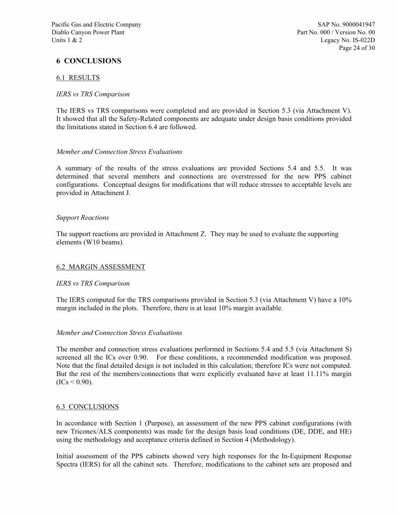
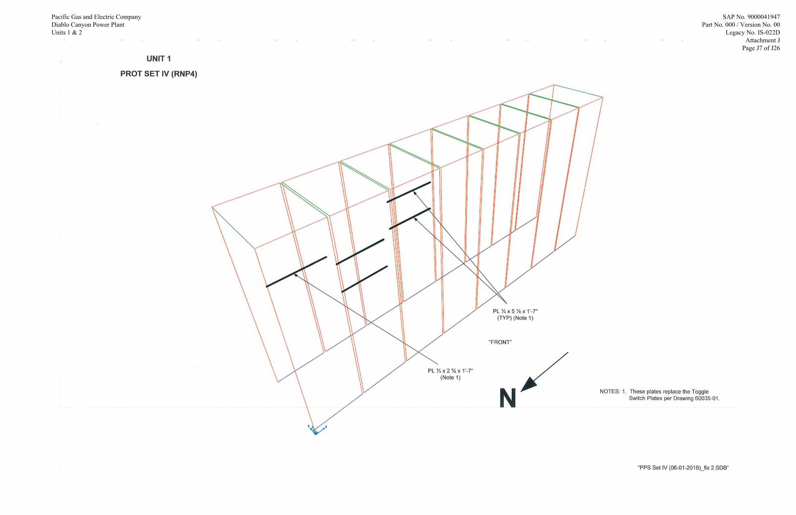
5.1.2.3 PPS SET IV / PCS GROUP 4 (8-BAY CABINET LINEUP) PPS Set IV consists of Racks 14 – 16 and PCS Group 4 consists of Racks 28 – 32. The origin is located on the lower Northwest corner. Preliminary analysis showed very high responses for the toggle switch plates (0.1345” x 2.75” x 19”) [Drawing 60035-01 (Ref. 3)] for all the PPS cabinets in the front-to-back direction. To reduce the responses, modifications are proposed and details are provided in Attachment J. The modification consists of increasing the toggle switch plate thicknesses and sizes to stiffen the support. The SAP2000 model with the proposed modifications is provided in Attachment N. The modal analysis results are summarized below (only the most significant modes are shown).
Mode Direction Frequency (Hz) Modal Participating Mass Ratio
2 Y (Front-to-Back) 16.14 0.15 5 Y (Front-to-Back) 18.98 0.33 6 X (Side-to-Side) 20.14 0.10 19 X (Side-to-Side) 23.50 0.10 20 X (Side-to-Side) 24.24 0.17 48 X (Side-to-Side) 31.28 0.15 49 Y (Front-to-Back) 35.55 0.14 50 Z (Vertical) 110.34 0.74
Pacific Gas and Electric Company Diablo Canyon Power Plant Units 1 & 2
SAP No. 9000041947 Part No. 000 / Version No. 00
Legacy No. IS-022D Page 18 of 30

5.1.3 LOAD CASES There are two load cases that are of concern. 1. Dead Loads (DL) 2. Seismic Loads 5.1.3.1 DEAD LOADS The dead loads include the self-weight of the existing and new cabinet members, and the new components. It is defined as “DEAD” in the SAP2000 models. 5.1.3.2 SEISMIC LOADS There are three seismic events that are of concern: DE, DDE, and HE. For these cases, linear modal time-history analyses are performed to determine the seismic response. As such, a modal analysis load case is also defined to determine the natural vibration modes of the cabinet structure. The results of this analysis provide the basis for the time-history load cases. To account for the mass not captured in the eigenvector solution, a static correction mode (or missing mass mode) is computed in SAP2000 to determine the residual rigid response. The acceleration time-history functions developed in Attachment A are used as input into the time-history analyses to simulate the support motion (Aux. Building EL. 128’ floor). The following is a list of the text files generated from the Response Spectrum Generator (RSG) program (in Attachment A) that are imported into the SAP2000 models. Note that the DDE load is 2 x DE load by definition. Thus, the DE responses used in this calculation are computed by dividing the DDE responses by 2.
Time-History Case Text File Name DDE NS TH_DDE_NS.txt DDE EW TH_DDE_EW.txt
DDE NS Vertical TH_DDE_NS_V.txt DDE EW Vertical TH_DDE_EW_V.txt
HE NS TH_H_NS.txt HE EW TH_H_EW.txt
HE Vertical TH_H_V.txt
Pacific Gas and Electric Company Diablo Canyon Power Plant Units 1 & 2
SAP No. 9000041947 Part No. 000 / Version No. 00
Legacy No. IS-022D Page 19 of 30

The NS, EW, and vertical components of each earthquake are applied simultaneously in a single analysis. This approach is recognized in Regulatory Guide 1.92 (Ref. 24) provided that the three components of earthquake are statistically independent (this has been verified and is documented in Attachment A). Therefore, the Load Cases defined in the SAP2000 models are as follows:
Load Case Time History Case
DDE_1 DDE NS DDE EW
DDE EW Vertical
DDE_2 DDE NS DDE EW
DDE NS Vertical
Hosgri HE NS HE EW
HE Vertical The modal damping, as defined in Section 3 Item 5, considered is as follows. Note that the DE and DDE load cases have the same damping value.
Load Case Modal Damping
(Percentage of Critical Damping)
DDE_1 and DDE_2 2% Hosgri 7%
Pacific Gas and Electric Company Diablo Canyon Power Plant Units 1 & 2
SAP No. 9000041947 Part No. 000 / Version No. 00
Legacy No. IS-022D Page 20 of 30

5.1.4 LOAD COMBINATIONS The load combinations used for the stress analysis discussed in Sections 5.4 (Member Evaluations) and 5.5 (Connection Evaluations) are: DEAD + ½DDE_1 DEAD + ½DDE_2
DEAD + DDE_1
DEAD + DDE_2
DEAD + Hosgri
Pacific Gas and Electric Company Diablo Canyon Power Plant Units 1 & 2
SAP No. 9000041947 Part No. 000 / Version No. 00
Legacy No. IS-022D Page 21 of 30

5.2 IN-EQUIPMENT RESPONSE SPECTRA In-Equipment Response Spectra (IERS) are generated for critical nodes identified in Attachment O for all four models documented in Attachments K through N. The named sets of IERS, which include the nodes, earthquake case, damping, direction, and percent widening are documented in Attachments K through N. A map of the location of the named sets in the PPS cabinets is included in Attachment O and the required IERS plots are provided in Attachment R. 5.3 COMPONENT QUALIFICATIONS The qualifications of the Safety-Related components are provided in Attachment V. All the comparison plots presented in Figures V-1 through V-30c in Attachment V show that the TRS envelope the RRS, except at around 2 Hz and below in some cases. These un-enveloping cases are justified in Attachment V. Thus the tested components listed in Table V-1 (Attachment V) are qualified for the seismic loads of the design environment of the PPS cabinets. Some items in Table V-1 (as marked in the “Notes” column) required specific analysis, evaluation, or justification. These analyses, evaluations, or justifications are included in Attachment W, concluding that these items are also qualified for the seismic loads of the design environment of the PPS cabinets. These conclusions are valid, contingent with the execution of the recommended bracing modifications and member and joint repairs (see Attachment J) on the PPS cabinet line-ups as evaluated in this calculation. 5.4 MEMBER EVALUATIONS The member evaluations are provided in Attachment S. The initial evaluations are based on enveloping forces/moments from the time-history analyses. Members shown to be unacceptable (IC > 0.90) using this approach are re-evaluated on a time-step basis. Note that a maximum IC of 0.90 is used to provide margin for future modifications. The time-step by time-step evaluation is performed at each station of each frame member at each time step. This is done using a post-processing script. The post-processing script and validation for this evaluation is documented in Attachment T. A summary of the remaining overstressed members with ICs greater than 0.90 following the time-step by time-step evaluation is provided in Attachment J. To resolve these overstress conditions, conceptual designs have been developed for modifications to the cabinets that will reduce member stresses to acceptable levels. These recommended modifications are provided in Attachment J. Analysis based on comparison of section properties, preliminary calculations and engineering judgment provide a high level of confidence that these modifications will produce the reduction of stresses required to meet the acceptance criteria. Development of the final design for the modifications and preparation of the required calculations supporting that design will be provided as part of the engineering change documentation required for installation of the modifications. It is noted that a few of the L2 x 11/16 vertical angles in the new racks and front-to-back members in the existing cabinet require reinforcement, as shown in Attachment J. The section properties for these
Pacific Gas and Electric Company Diablo Canyon Power Plant Units 1 & 2
SAP No. 9000041947 Part No. 000 / Version No. 00
Legacy No. IS-022D Page 22 of 30

members have not been revised in the SAP2000 models. The effect of this reinforcement will be to increase the stiffness of the supporting structure; therefore, it is judged to have no adverse impact on the response of the cabinets. 5.5 CONNECTION EVALUATIONS The member end connection evaluations are provided in Attachment S. The initial evaluations are based on enveloping forces/moments from the time-history analyses. Connections shown to be unacceptable (IC > 0.90) using this approach is re-evaluated on a time-step basis. Note that a maximum IC of 0.90 is used to provide margin for future modifications. The time-step by time-step evaluation is performed for critical joint locations identified in Attachment S at each time step. This is done using a post-processing script. The post-processing script and validation for this evaluation is documented in Attachment U. A summary of the remaining overstressed connections with ICs greater than 0.90 following the time-step by time-step evaluation is provided in Attachment J. To resolve these overstress conditions, conceptual designs have been developed for modifications to the cabinets that will reduce connection stresses to acceptable levels. These recommended modifications are provided in Attachment J. Analysis based on comparison of section properties, preliminary calculations and engineering judgment provide a high level of confidence that these modifications will produce the reduction of stresses required to meet the acceptance criteria. Development of the final design for the modifications and preparation of the required calculations supporting that design will be provided as part of the engineering change documentation required for installation of the modifications.
Pacific Gas and Electric Company Diablo Canyon Power Plant Units 1 & 2
SAP No. 9000041947 Part No. 000 / Version No. 00
Legacy No. IS-022D Page 23 of 30
6 CONCLUSIONS 6.1 RESULTS IERS vs TRS Comparison The IERS vs TRS comparisons were completed and are provided in Section 5.3 (via Attachment V). It showed that all the Safety-Related components are adequate under design basis conditions provided the limitations stated in Section 6.4 are followed. Member and Connection Stress Evaluations A summary of the results of the stress evaluations are provided Sections 5.4 and 5.5. It was determined that several members and connections are overstressed for the new PPS cabinet configurations. Conceptual designs for modifications that will reduce stresses to acceptable levels are provided in Attachment J. Support Reactions The support reactions are provided in Attachment Z. They may be used to evaluate the supporting elements (W10 beams). 6.2 MARGIN ASSESSMENT IERS vs TRS Comparison The IERS computed for the TRS comparisons provided in Section 5.3 (via Attachment V) have a 10% margin included in the plots. Therefore, there is at least 10% margin available. Member and Connection Stress Evaluations The member and connection stress evaluations performed in Sections 5.4 and 5.5 (via Attachment S) screened all the ICs over 0.90. For these conditions, a recommended modification was proposed. Note that the final detailed design is not included in this calculation; therefore ICs were not computed. But the rest of the members/connections that were explicitly evaluated have at least 11.11% margin (ICs < 0.90). 6.3 CONCLUSIONS In accordance with Section 1 (Purpose), an assessment of the new PPS cabinet configurations (with new Triconex/ALS components) was made for the design basis load conditions (DE, DDE, and HE) using the methodology and acceptance criteria defined in Section 4 (Methodology). Initial assessment of the PPS cabinets showed very high responses for the In-Equipment Response Spectra (IERS) for all the cabinet sets. Therefore, modifications to the cabinet sets are proposed and
Pacific Gas and Electric Company Diablo Canyon Power Plant Units 1 & 2
SAP No. 9000041947 Part No. 000 / Version No. 00
Legacy No. IS-022D Page 24 of 30

are provided in Attachment J to bring the responses to acceptable levels for the IERS. They include new internal bracing, external bracing, and new plate members to be installed. The stress analysis followed and found overstresses in several members/connections (considered IC > 0.90 to be overstressed). Recommended modifications for the overstressed members are provided in Attachment J. Analysis based on comparison of section properties, preliminary calculations and engineering judgment provide a high level of confidence that these modifications will produce the reduction of stresses required to meet the acceptance criteria. Development of the final design for the modifications and preparation of the required calculations supporting that design is not included in this calculation, but will be provided as part of the engineering change documentation required for installation of the modifications. The support reactions are provided in Attachment Z. They may be used to evaluate the supporting elements (W10 beams). 6.4 LIMITATIONS The following limitations shall be implemented before the PPS cabinets are relied upon to perform their intended function. 1. The ASSUMPTIONS identified in Section 2.1 shall be verified. 2. The modifications to the cabinets provided in Attachment J shall be implemented. Note that detailed calculations for the new bracing connections and the cabinet/rack members/connections shall be completed before implementation (See Section 6.3). 6.5 DOCUMENT IMPACT ASSESSMENT This calculation is exclusively a qualification for the framing and the supported I&C components within the PPS cabinets. This calculation does not impact the licensing basis, operations, or plant procedures.
Pacific Gas and Electric Company Diablo Canyon Power Plant Units 1 & 2
SAP No. 9000041947 Part No. 000 / Version No. 00
Legacy No. IS-022D Page 25 of 30
7 REFERENCES Note that individual attachments may have its own reference list. 1. License Amendment Request (LAR) 11-07, “Process Protection System Replacement” (PG&E Letter DCL-11-104, dated October 26, 2011) (Unlinked) 2. Walkdown of DCPP PPS and PCS Cabinets (Walkdown Report dated 2016-03-01) (Attachment D) (Unlinked) 3. DIT-50831673-001 (dated 2016-06-22), “Process Protection Rack Design and Layout” (PPS Rack Assembly Drawings) (Attachment B) (Unlinked) 4. DCPP Drawing No. 663222, Sheet 1, Rev. 3, “I&C / Process Control System / Rack Cabinet Match Joint Bolt Arrangement” (Unit 1) (Linked Input) 5. DCPP Drawing No. 663222, Sheet 89, Rev. 4, “I&C / Rack Cabinet Match Joint Bolt Arrangement” (Unit 2) (Linked Input) 6. DCPP Drawing No. 6010908, Sheet 402, Rev. 3, “I&C / Eagle 21 Standard AMCO Replacement Cabinet General Assembly II” (Linked Input) 7. DCPP Drawing No. 6010908, Sheet 416, Rev. 10, “Eagle 21 Standard Cabinet Structure Assembly” (Linked Input) 8. DCPP Drawing No. 6010908, Sheet 414, Rev. 2, “Eagle 21 Standard Cabinet Base Assembly and Mounting Details” (Linked Input) 9. DCPP Drawing No. 6010908, Sheet 417, Rev. 6, “Eagle 21 Standard Cabinet Structure Assembly” (Linked Input) 10. DCPP Drawing No. 663222, Sheet 217, Page 1, Rev. 2, “Side Sheer Plate” (Linked Input) 11. DIT-50831673-002 (dated 2016-06-13), “Process Protection Rack Design and Layout” (New PPS Component Weights) (Attachment C) (Unlinked) 12. Calculation IS-022 (SAP No. 9000023515), Rev. 2, “Seismic Qualification of Process Control and 7100 Protection System” (Linked Input) 13. Calculation IS-022A (SAP No. 9000023641), Rev. 0, “Eagle 21 Process Protection System” (Linked Input) 14. Calculation IS-022B (SAP No. 9000040858), Rev. 0, “Replacement of Westinghouse 7100 Process Control Racks” (Linked Input) 15. NOT USED 16. Diablo Canyon Power Plant Units 1 and 2, Final Safety Analysis Report Update, Rev. 22 (Unlinked)
Pacific Gas and Electric Company Diablo Canyon Power Plant Units 1 & 2
SAP No. 9000041947 Part No. 000 / Version No. 00
Legacy No. IS-022D Page 26 of 30

17. DCPP Drawing No. 59658, Sheet 1, Rev. 22, “Platform Area H / EL. 128’-3” / Plan, Sections & Details” (Linked Input) 18. DCPP Drawing No. 57735, Sheet 1, Rev. 11, “Equipment Location / Miscellaneous Plans / Auxiliary Building / EL. 125’-0”, 127’-0”, 154’-0”, 163’-0” ” (Linked Input) 19. DCPP Drawing No. 694034, Sheet 78, Rev. 1, “Cable Spreading Room / Aux. Bldg / Structural Conduit Ducts” (Linked Input) 20. DCPP Drawing No. 6003029, Sheet 92, Rev. 2, “Cable Spreading Room / Unit 2 / Structural Conduit Platform” (Linked Input) 21. DCPP Drawing No. 507612, Sheet 1, Rev. 16, “Electrical / Arrangement of Electrical Equipment @ EL. 128’-0” / Area H” (Linked Input) 22. PG&E Letter DCL-14-036 (dated 2014-04-30), “Response to Request for Additional Information on License Amendment Request for Digital Process Protection System Replacement” (Letter from PG&E to NRC) (Unlinked) 23. Institute of Electrical and Electronics Engineers, Inc., IEEE 323-1974, “IEEE Standard for Qualifying Class 1E Equipment for Nuclear Power Generating Stations” (Unlinked) 24. U. S. Nuclear Regulatory Commission (NRC), Regulatory Guide 1.92, Rev. 3, “Combining Modal Responses and Spatial Components in Seismic Response Analysis” (Unlinked) 25. DCPP DCM T-10, Rev. 8A, “Seismic Qualification of Equipment” (Design Criteria Memorandum) (Linked Input) 26. DCPP DCM T-6, Rev. 10, “Seismic Analysis of Structures” (Linked Input) 27. American Iron and Steel Institute (AISI), “Specification for Design of Cold-Formed Steel Structural Members”, 1968 Edition (Unlinked) 28. American Institute of Steel Construction, “Specification for the Design, Fabrication and Erection of Structural Steel for Buildings”, 7th Edition (Unlinked) 29. Calculation SQME-77 (9000018912), Rev. 0, “Calculate Allowable Stresses for Seismic Qualification of Equipment” (Linked Input) 30. DCPP Drawing 663222, Sheet 26, Rev. 7, “I&C / Process Control System / Rack 25 Arrangement / RNO3A” (Unit 1) (Linked Input) 31. DCPP Drawing 663222, Sheet 27, Rev. 11, “I&C / Process Control System / Rack 26 Arrangement / RNO3B” (Unit 1) (Linked Input) 32. DCPP Drawing 663222, Sheet 28, Rev. 10, “I&C / Process Control System / Rack 27 Arrangement / RNO3C” (Unit 1) (Linked Input) 33. DCPP Drawing 663222, Sheet 29, Rev. 7, “I&C / Process Control System / Rack 28 Arrangement / RNO4A” (Unit 1) (Linked Input)
Pacific Gas and Electric Company Diablo Canyon Power Plant Units 1 & 2
SAP No. 9000041947 Part No. 000 / Version No. 00
Legacy No. IS-022D Page 27 of 30

34. DCPP Drawing 663222, Sheet 30, Rev. 7, “I&C / Process Control System / Rack 29 Arrangement / RNO4B” (Unit 1) (Linked Input) 35. DCPP Drawing 663222, Sheet 31, Rev. 10, “I&C / Process Control System / Rack 30 Arrangement / RNO4C” (Unit 1) (Linked Input) 36. DCPP Drawing 663222, Sheet 32, Rev. 5, “I&C / Process Control System / Rack 31 Arrangement / RNO4D” (Unit 1) (Linked Input) 37. DCPP Drawing 663222, Sheet 33, Rev. 6, “I&C / Process Control System / Rack 32 Arrangement / RNO4E” (Unit 1) (Linked Input) 38. DCPP Drawing 663222, Sheet 114, Rev. 3, “I&C / Process Control System / Rack Arrangement No. 25 / RNO3A” (Unit 2) (Linked Input) 39. DCPP Drawing 663222, Sheet 115, Rev. 6, “I&C / Process Control System / Rack Arrangement No. 26 / RNO3B” (Unit 2) (Linked Input) 40. DCPP Drawing 663222, Sheet 116, Rev. 9, “I&C / Process Control System / Rack Arrangement No. 27 / RNO3C” (Unit 2) (Linked Input) 41. DCPP Drawing 663222, Sheet 117, Rev. 3, “I&C / Process Control System / Rack Arrangement No. 28 / RNO4A” (Unit 2) (Linked Input) 42. DCPP Drawing 663222, Sheet 118, Rev. 5, “I&C / Process Control System / Rack Arrangement No. 29 / RNO4 B” (Unit 2) (Linked Input) 43. DCPP Drawing 663222, Sheet 119, Rev. 7, “I&C / Process Control System / Rack Arrangement No. 30 / RNO4C” (Unit 2) (Linked Input) 44. DCPP Drawing 663222, Sheet 120, Rev. 4, “I&C / Process Control System / Rack Arrangement No. 31 / RNO4D” (Unit 2) (Linked Input) 45. DCPP Drawing 663222, Sheet 121, Rev. 5, “I&C / Process Control System / Rack Arrangement No. 32 / RNO4E” (Unit 2) (Linked Input) 46. PG&E Letter DCL-03-077 (dated June 24, 2003), “Response to NRC Questions Regarding License Amendment Request 02-03, “Spent Fuel Cask Handling” ” (Unlinked) 47. Connection Walkdown Report (dated 2016-06-22) (Attachment P) (Unlinked) 48. U. S. Nuclear Regulatory Commission (NRC), Regulatory Guide 1.60, Rev. 1, “Design Response Spectra for Seismic Design of Nuclear Power Plants” (Unlinked) 49. U. S. Nuclear Regulatory Commission (NRC), Regulatory Guide 1.122, Rev. 1, “Development of Floor Design Response Spectra for Seismic Design of Floor Supported Equipment or Components” (Unlinked) 50. U. S. Nuclear Regulatory Commission (NRC), NUREG/CR-6728, Rev. 0, “Technical Basis for Revision of Regulatory Guidance on Design Ground Motions: Hazard-and Risk-Consistent Ground Motion Spectra Guidelines” (Unlinked)
Pacific Gas and Electric Company Diablo Canyon Power Plant Units 1 & 2
SAP No. 9000041947 Part No. 000 / Version No. 00
Legacy No. IS-022D Page 28 of 30

51. U. S. Nuclear Regulatory Commission (NRC), NUREG/CR-6865, Rev. 0, “Parametric Evaluation of Seismic Behavior of Freestanding Spent Fuel Dry Cask Storage System” (Unlinked) 52. U. S. Nuclear Regulatory Commission (NRC), NUREG-0800 (Standard Review Plan for the Review of Safety Analysis Reports for Nuclear Power Plants: LWR Edition), Chapter 3 (Design of Structures, Components, Equipment, and Systems), Section 3.7.1, Rev. 3, “Seismic Design Parameters” (Unlinked) 53. Pacific Earthquake Engineering Research Center (PEER) Strong Motion Database (Unlinked) 54. DCPP DCM C-17, Rev. 19, “Hosgri Response Spectra” (Linked Input) 55. DCPP DCM C-25, Rev. 5, “Design Earthquake Response Spectra for Structures, Systems, and Components” (Linked Input) 56. DCPP DCM C-30, Rev. 9A, “Double Design Earthquake Response Spectra for Structures, Systems, and Components” (Linked Input) 57. NOT USED 58. DCPP Drawing 57733 Sheet 1, Rev. 19, “Mechanical / Equipment Location / Section “FF” Auxiliary, Fuel Handling & Turbine Buildings” (Linked Input) 59. American Institute of Steel Construction, “Specification for Structural Steel Buildings – Allowable Stress Design and Plastic Design”, 9th Edition (Unlinked) 60. AMCO Drawings for FX Frame Connections (Attachment Q) (Unlinked) 61. Triconex Drawing 2000361-001, Rev. A, “Baffle Heat Deflector” (Attachment W) (Unlinked) 62. American Society of Mechanical Engineers (ASME), NQA-1-2012, “Quality Assurance Requirements for Nuclear Facility Applications” (Unlinked) 63. DCPP Drawing No. 663222-267, Sheet 267, Rev. 2, “Qualification Report for KEPCO HSF Series Power Supplies, Moore Converters” (Linked Input) 64. DCPP Drawing No. 663222-268, Sheet 268, Rev. 2, “Supplemental Qualification Report for KEPCO HSF Series Power Supplies & Mounting Rack, and Moore Signal Isolator” (Linked Input) 65. NOT USED 66. DCPP RPE 8000004597, Rev. 0, “Replacement or New Part Evaluation (RPE), Subject: Ground terminal blocks used as end blocks with the Triconex field termination panels (FTP) …” (Linked Input) 67. Report S1100.0 (SAP No. 9000041788), Rev. 0, “Seismic Qualification Analysis Report for Seismically Insensitive Items” (Linked Input) 68. DCPP Drawing No. 6010908, Sheet 413, Rev. 7, “Eagle 21 Standard Cabinet Base Assembly and Mounting Details” (Linked Input)
Pacific Gas and Electric Company Diablo Canyon Power Plant Units 1 & 2
SAP No. 9000041947 Part No. 000 / Version No. 00
Legacy No. IS-022D Page 29 of 30

69. NOT USED 70. DCPP Drawing No. 6010908, Sheet 415, Rev. 2, “Eagle 21 Standard Cabinet Base Assembly and Mounting Details” (Linked Input) 71. DCPP DCP 1000000237, Rev. 1, “Replace Westinghouse Hagan 7100 Process Control System (PCS)” (Linked Input) 72. Calculation ES-33 (SAP No. 9000012805), Rev. 10, “Seismic Qualification of POV1 and POV2” (Linked Input) 73. Report S1612.4 (SAP No. 9000041984), Rev. 0 (dated June 2016), “Curtiss-Wright Seismic Qualification Test Report for Multiple Items” (Linked Input) 74. Westinghouse Report 6116-00204, Rev. 2 (July 2015), “Diablo Canyon Process Protection System, ALS Subsystem Equipment Qualification Evaluation” (Unlinked) 75. Westinghouse Report EQLR-224B, Rev. 1 (April 2012), “Seismic Test Report for the Advanced Logic System (ALS)” (Unlinked) 76. Curtiss-Wright report S1612.0, Rev. 0 (May 2016), “Seismic Qualification Test Report for Multiple Items” (Unlinked) 77. Curtiss-Wright report S1612.0, Rev. 0 (April 2016), “Seismic Qualification Test Procedure for Multiple Items” (Unlinked) 78. Westinghouse Report EQ-QR-120-PGE, Rev. 1 (July 2015), “Advanced Logic System and Line Sense Module Equipment Qualification Summary Report” (Unlinked) 79. Cooper Bussmann, Fast-Acting 1/4" and 1 1/4" Glass Tube Fuses, AGC Series (See page W10) (Unlinked) 80. EPRI Report TR-105849, G-STERI No. C-94001, Rev. 3 (Unlinked) 81. Pomona Electronics Product Datasheet, Model 2269, Insulated Double Banana Jack (See page W11) (Unlinked) 82. Machinery's Handbook, 26th Edition (Unlinked) 83. EPRI Report TR-105849, G-STERI Evaluation No. E-95029 (Unlinked) 84. Potter & Brumfield KUP Series Relay Product Sheet (See pages W13-W17) (Unlinked) 85. DIT-50831673-003 (dated 2016-07-19), “Transmittal of Westinghouse Seismic Qualification Reports” (Attachment AA) (Unlinked) 86. Weidmüller Interface GmbH & Co. website (DIN Rail Vendor), http://catalog.weidmueller.com/catalog/Start.do?localeId=en_DE&ObjectID=0236500000 (Unlinked)
Pacific Gas and Electric Company Diablo Canyon Power Plant Units 1 & 2
SAP No. 9000041947 Part No. 000 / Version No. 00
Legacy No. IS-022D Page 30 of 30

Pacific Gas and Electric Company Diablo Canyon Power Plant Units 1 & 2
ATTACHMENT J
Modification Sketches
Pre~.ared by: <'') -7Af'/! - .
~~~~//__.,, (. f<-._:.. OfS - 0 > - 2.0 I b
Soe Moe I Tony Kim Date
Reviewed by:
~r- Date
SAP No. 9000041947 Part No. 000 I Version No. 00
Legacy No. IS-022D Attachment .I
Page Jl of .126

GLOBAL MODIFICATION SKETCHES
Pacific Gas and Electric Company Diablo Canyon Power Plant Units 1 & 2
SAP No. 9000041947 Part No. 000 / Version No. 00
Legacy No. IS-022D Attachment J
Page J2 of J26

Pacific Gas and Electric Company Diablo Canyon Power Plant Units 1 & 2
SAP No. 9000041947 Part No. 000 / Version No. 00
Legacy No. IS-022D Attachment J
Page J3 of J26

Pacific Gas and Electric Company Diablo Canyon Power Plant Units 1 & 2
SAP No. 9000041947 Part No. 000 / Version No. 00
Legacy No. IS-022D Attachment J
Page J4 of J26

Pacific Gas and Electric Company Diablo Canyon Power Plant Units 1 & 2
SAP No. 9000041947 Part No. 000 / Version No. 00
Legacy No. IS-022D Attachment J
Page J5 of J26

Pacific Gas and Electric Company Diablo Canyon Power Plant Units 1 & 2
SAP No. 9000041947 Part No. 000 / Version No. 00
Legacy No. IS-022D Attachment J
Page J6 of J26
Pacific Gas and Electric Company Diablo Canyon Power Plant Units 1 & 2
SAP No. 9000041947 Part No. 000 / Version No. 00
Legacy No. IS-022D Attachment J
Page J7 of J26

Pacific Gas and Electric Company Diablo Canyon Power Plant Units 1 & 2
SAP No. 9000041947 Part No. 000 / Version No. 00
Legacy No. IS-022D Attachment J
Page J8 of J26

LOCAL MEMBER MODIFICATION SKETCHES
Pacific Gas and Electric Company Diablo Canyon Power Plant Units 1 & 2
SAP No. 9000041947 Part No. 000 / Version No. 00
Legacy No. IS-022D Attachment J
Page J9 of J26

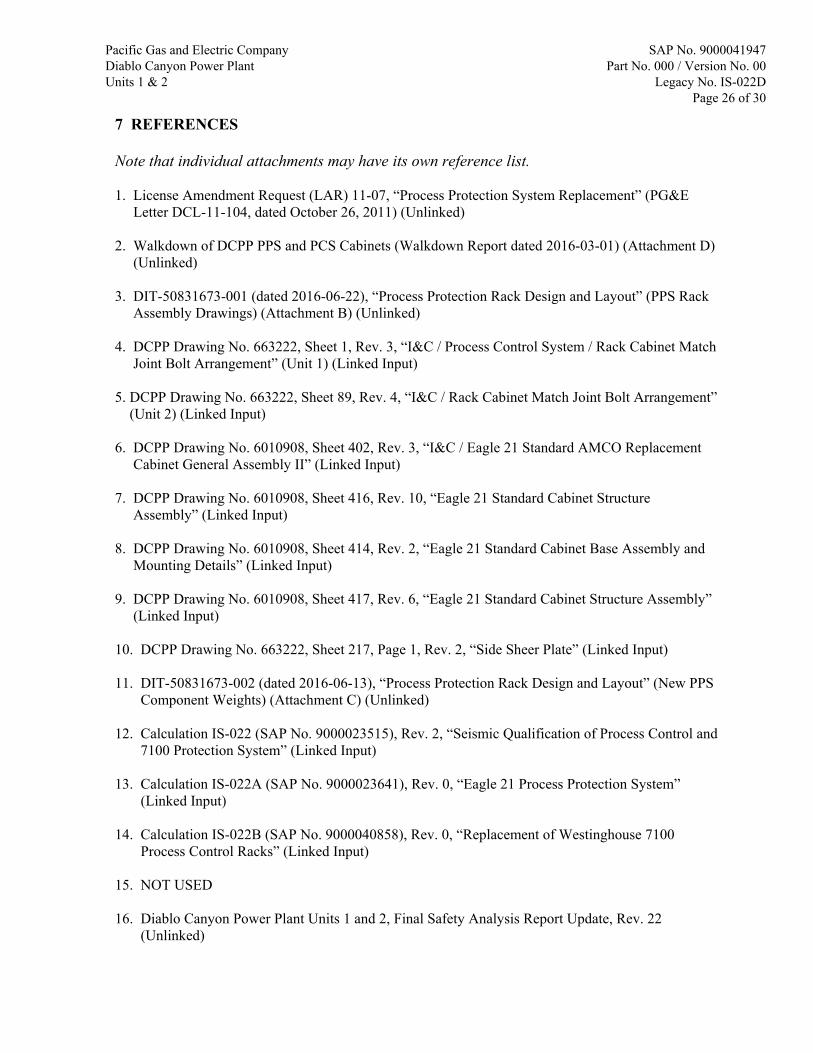
The following tables summarize the SAP 2000 model members and joints where overstressed conditions were found in the analysis provided in Attachment S. Conceptual designs for modifications that will reduce stresses in these members to acceptable levels are provided on the following pages. Forces and moments applicable for the final design of the member reinforcement are provided in Attachment AC.
Table J-1 – Overstressed Members
Cabinet Set No. Model
Member No.
Member Size
Max. IC Governing Limit State
PPS Sets I & 2 435 21 1.035 Combined Bending + Axial U1 PPS Set III / PCS Group 3 - - - - U2 PPS Set III / PCS Group 3 - - - -
PPS Set IV / PCS Group 4 106-1 21 1.049 Combined Bending + Axial 2511 L2x11/16 1.834 Combined Bending + Axial
Notes: 1. Model Section Type “2” – see Ref. 2, p. 39, “Sketch No. 2”.
Pacific Gas and Electric Company Diablo Canyon Power Plant Units 1 & 2
SAP No. 9000041947 Part No. 000 / Version No. 00
Legacy No. IS-022D Attachment J
Page J10 of J26
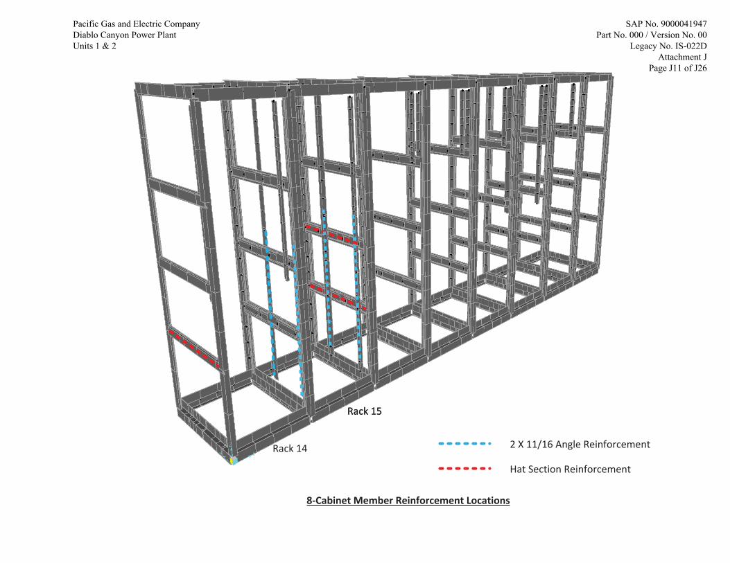
Rack 14
Rack 15Rack 15
2 X 11/16 Angle Reinforcement
Hat Section Reinforcement
8-Cabinet Member Reinforcement Locations
Pacific Gas and Electric Company Diablo Canyon Power Plant Units 1 & 2
SAP No. 9000041947 Part No. 000 / Version No. 00
Legacy No. IS-022D Attachment J
Page J11 of J26

Hat Section Reinforcement
Rack 2
5-Cabinet Member Reinforcement Location
Pacific Gas and Electric Company Diablo Canyon Power Plant Units 1 & 2
SAP No. 9000041947 Part No. 000 / Version No. 00
Legacy No. IS-022D Attachment J
Page J12 of J26

0.6875"
2.0"
1.50
"
0.50
"0.
625"
2" X 11/16" Angle
Drill and countersink 0.3125" diameter holes to align with holes in 2" X 11/16" angle used for attachment to cabinet side members.
Reinforcement Detail for 2" X 11/16" Angle
Use ¼-20 countersunk machine screws with nuts and washers in lieu of hardware specified in Drawing Series 60000-01 in locations where reinforcing bar is added.
Drill and countersink 0.3125" diameter holes for attachment to cabinet side members.
Use ¼-20 countersunk machine screws with nuts and washer to attach reinforcement bar to in-place member.
Centerline of in-place member, reinforcing bar and machine screw hole.
Install this detail in Rack 15 on left rear 2" X 11/16" angle as shown on the preceding pages.
Install this detail in Rack 2 on left side member, Rack 14 on left side member, and Rack 15 on right side members as shown on the preceding pages.
Add 1 1/2” X 3/8" bar to angle in sections requiring reinforcement as determined by stress analysis.
Reinforcement Detail for In-Place Horizontal Front-to-Back “Hat” Section
In-place horizontal front-to-back “hat” section member.
Add 1 1/2” X 3/8" bar to front-to-back member in sections requiring reinforcement as determined by stress analysis.
Pacific Gas and Electric Company Diablo Canyon Power Plant Units 1 & 2
SAP No. 9000041947 Part No. 000 / Version No. 00
Legacy No. IS-022D Attachment J
Page J13 of J26

LOCAL MEMBER END CONNECTION MODIFICATION SKETCHES
Pacific Gas and Electric Company Diablo Canyon Power Plant Units 1 & 2
SAP No. 9000041947 Part No. 000 / Version No. 00
Legacy No. IS-022D Attachment J
Page J14 of J26
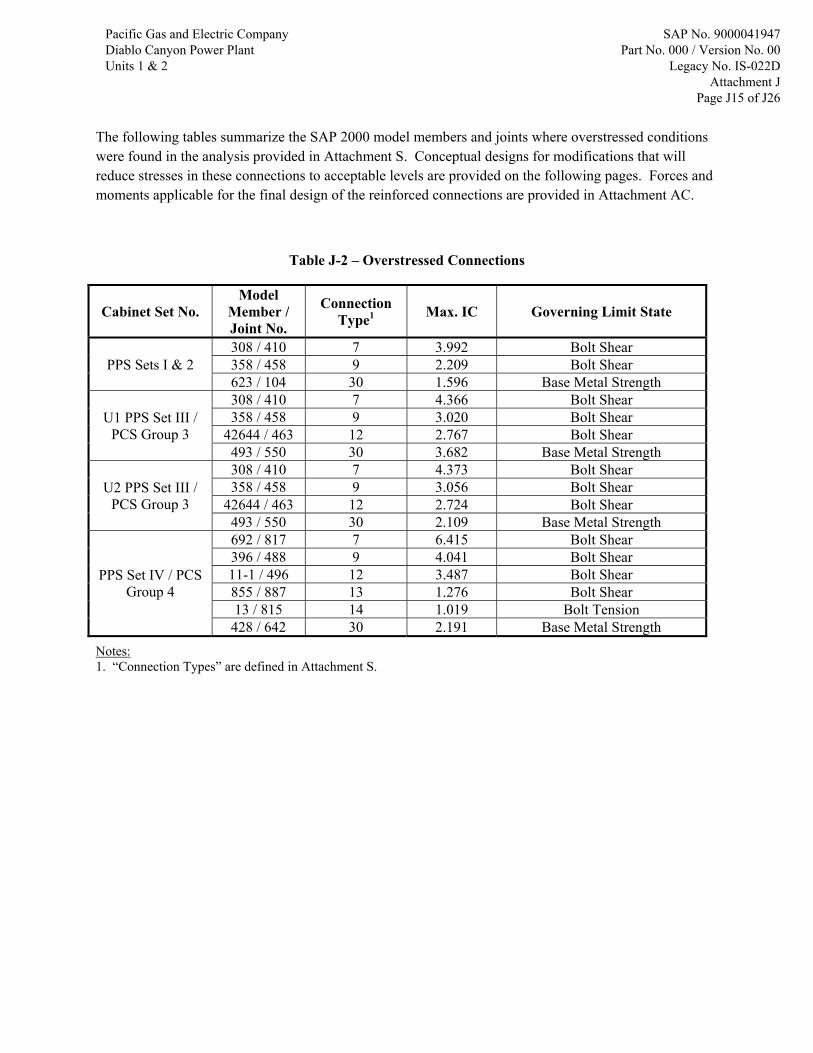
The following tables summarize the SAP 2000 model members and joints where overstressed conditions were found in the analysis provided in Attachment S. Conceptual designs for modifications that will reduce stresses in these connections to acceptable levels are provided on the following pages. Forces and moments applicable for the final design of the reinforced connections are provided in Attachment AC.
Table J-2 – Overstressed Connections
Cabinet Set No. Model
Member / Joint No.
Connection Type1 Max. IC Governing Limit State
PPS Sets I & 2 308 / 410 7 3.992 Bolt Shear 358 / 458 9 2.209 Bolt Shear 623 / 104 30 1.596 Base Metal Strength
U1 PPS Set III / PCS Group 3
308 / 410 7 4.366 Bolt Shear 358 / 458 9 3.020 Bolt Shear
42644 / 463 12 2.767 Bolt Shear 493 / 550 30 3.682 Base Metal Strength
U2 PPS Set III / PCS Group 3
308 / 410 7 4.373 Bolt Shear 358 / 458 9 3.056 Bolt Shear
42644 / 463 12 2.724 Bolt Shear 493 / 550 30 2.109 Base Metal Strength
PPS Set IV / PCS Group 4
692 / 817 7 6.415 Bolt Shear 396 / 488 9 4.041 Bolt Shear 11-1 / 496 12 3.487 Bolt Shear 855 / 887 13 1.276 Bolt Shear 13 / 815 14 1.019 Bolt Tension
428 / 642 30 2.191 Base Metal Strength
Notes: 1. “Connection Types” are defined in Attachment S.
Pacific Gas and Electric Company Diablo Canyon Power Plant Units 1 & 2
SAP No. 9000041947 Part No. 000 / Version No. 00
Legacy No. IS-022D Attachment J
Page J15 of J26

Total Number of Overstressed Connections
Number of Overstressed Joints for IC's SpecifiedIC > 1.0 IC > 0.95 IC > 0.9
Bolted 23 23 24Welded 6 7 7Bolted 10 13 14
Welded 6 6 6Bolted 13 13 13
Welded 3 4 5Bolted 13 13 13
Welded 6 6 6
Breakdown of Overstressed Connection Counts
Number of Overstressed Joints for IC's SpecifiedIC > 1.0 IC > 0.95 IC > 0.9
Connection 7 8 8 8Connection 9 8 8 9Connection 12 4 4 4Connection 13 2 2 2Connection 14 1 1 1
Welded Connection 30 6 7 7Connection 7 8 11 12Connection 9 2 2 2
Welded Connection 30 6 6 6Connection 7 6 6 6Connection 9 4 4 4Connection 12 3 3 3
Welded Connection 30 3 4 5Connection 7 6 6 6Connection 9 4 4 4Connection 12 3 3 3
Welded Connection 30 6 6 6
ConnectionType
8 Cabinet
6 Cabinet Unit 2
Bolted
Model Joint Type
6 Cabinet Unit 2Bolted
Model Joint Type
6 Cabinet Unit 1
5 Cabinet
8 Cabinet
6 Cabinet Unit 1Bolted
5 CabinetBolted
Pacific Gas and Electric Company Diablo Canyon Power Plant Units 1 & 2
SAP No. 9000041947 Part No. 000 / Version No. 00
Legacy No. IS-022D Attachment J
Page J16 of J26

8-C
abin
etO
vers
tres
sed
Bol
ted
Con
nect
ion
Loca
tions
Con
nect
ion
7
Rac
k14
Rac
k15
Rac
k16
Con
nect
ion
9
Con
nect
ion
12
Con
nect
ion
13
Con
nect
ion
14
Pacific Gas and Electric Company Diablo Canyon Power Plant Units 1 & 2
SAP No. 9000041947 Part No. 000 / Version No. 00
Legacy No. IS-022D Attachment J
Page J17 of J26

8-C
abin
etO
vers
tres
sed
Wel
ded
Con
nect
ion
Loca
tions
Con
nect
ion
30
Rac
k14
Rac
k15
Rac
k16
CHEC
KS F
OR
CON
NEC
TIO
NS
29 T
HRO
UGH
32
CO
NTA
IN U
NVA
RIFI
ED A
SSU
MPT
ION
S TH
AT R
EQU
IRE
FUTU
RE V
ERIF
ICAT
ION
.
Pacific Gas and Electric Company Diablo Canyon Power Plant Units 1 & 2
SAP No. 9000041947 Part No. 000 / Version No. 00
Legacy No. IS-022D Attachment J
Page J18 of J26

Con
nect
ion
7C
onne
ctio
n9
Rac
k5
Rac
k1
Rac
k2
5-C
abin
etO
vers
tres
sed
Bol
ted
Con
nect
ion
Loca
tions
Rac
k3
Rac
k4
Pacific Gas and Electric Company Diablo Canyon Power Plant Units 1 & 2
SAP No. 9000041947 Part No. 000 / Version No. 00
Legacy No. IS-022D Attachment J
Page J19 of J26

5-C
abin
etO
vers
tres
sed
Wel
ded
Con
nect
ion
Loca
tions
Con
nect
ion
30R
ack
2
Rac
k1
Rac
k5
CHEC
KS F
OR
CON
NEC
TIO
NS
29 T
HRO
UGH
32
CO
NTA
IN U
NVA
RIFI
ED A
SSU
MPT
ION
S TH
AT R
EQU
IRE
FUTU
RE V
ERIF
ICAT
ION
.
Pacific Gas and Electric Company Diablo Canyon Power Plant Units 1 & 2
SAP No. 9000041947 Part No. 000 / Version No. 00
Legacy No. IS-022D Attachment J
Page J20 of J26

6-C
abin
et(U
nit1
)Ove
rstr
esse
dB
olte
dC
onne
ctio
nLo
catio
ns
Rac
k11
Rac
k12
Rac
k13 Con
nect
ion
7C
onne
ctio
n9
Con
nect
ion
12
Pacific Gas and Electric Company Diablo Canyon Power Plant Units 1 & 2
SAP No. 9000041947 Part No. 000 / Version No. 00
Legacy No. IS-022D Attachment J
Page J21 of J26
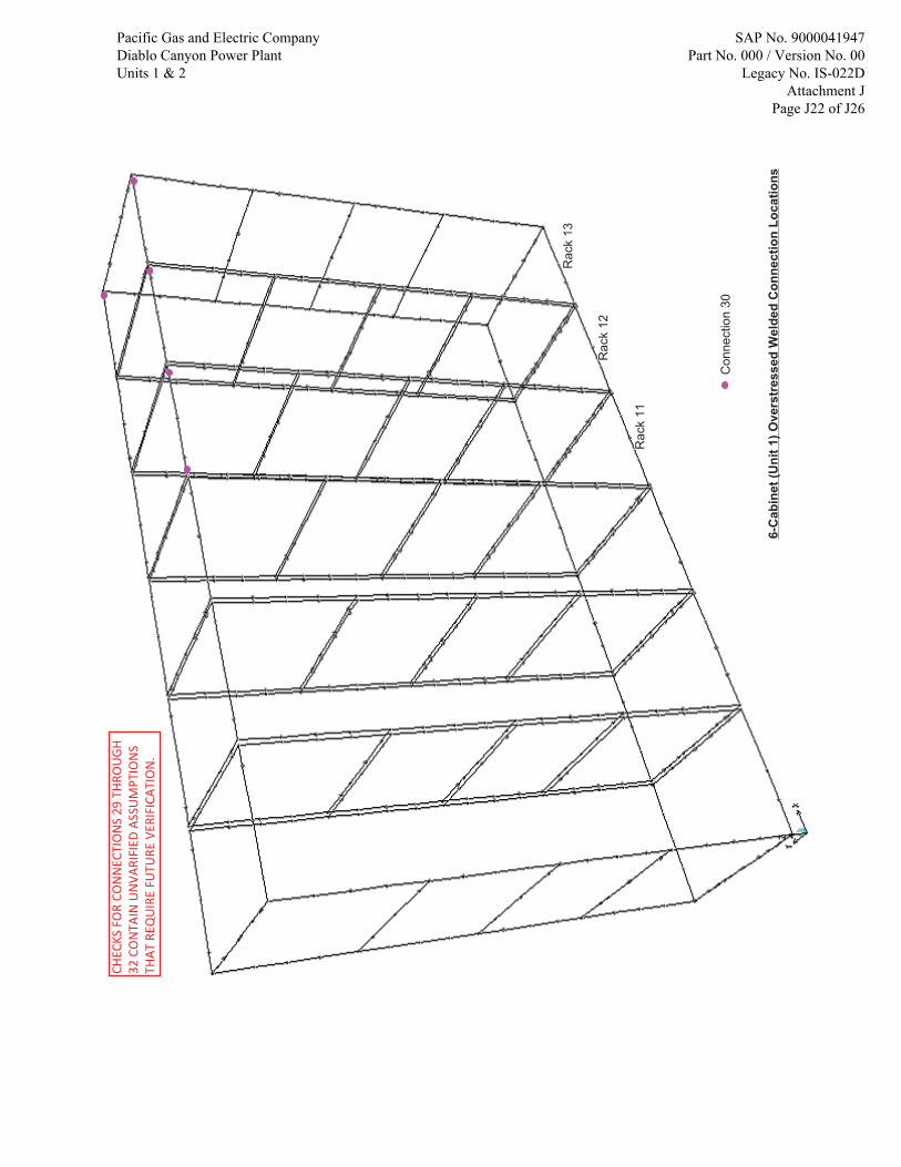
Con
nect
ion
30
6-C
abin
et(U
nit1
)Ove
rstr
esse
dW
elde
dC
onne
ctio
nLo
catio
ns
Rac
k11
Rac
k12
Rac
k13
CHEC
KS F
OR
CON
NEC
TIO
NS
29 T
HRO
UGH
32
CO
NTA
IN U
NVA
RIFI
ED A
SSU
MPT
ION
S TH
AT R
EQU
IRE
FUTU
RE V
ERIF
ICAT
ION
.
Pacific Gas and Electric Company Diablo Canyon Power Plant Units 1 & 2
SAP No. 9000041947 Part No. 000 / Version No. 00
Legacy No. IS-022D Attachment J
Page J22 of J26

Con
nect
ion
7C
onne
ctio
n9
Con
nect
ion
12
6-C
abin
et(U
nit2
)Ove
rstr
esse
dB
olte
dC
onne
ctio
nLo
catio
ns
Rac
k11
Rac
k12
Rac
k13
Pacific Gas and Electric Company Diablo Canyon Power Plant Units 1 & 2
SAP No. 9000041947 Part No. 000 / Version No. 00
Legacy No. IS-022D Attachment J
Page J23 of J26

Con
nect
ion
30
6-C
abin
et(U
nit2
)Ove
rstr
esse
dW
elde
dC
onne
ctio
nLo
catio
ns
Rac
k11
Rac
k12
Rac
k13
CHEC
KS F
OR
CON
NEC
TIO
NS
29 T
HRO
UGH
32
CO
NTA
IN U
NVA
RIFI
ED A
SSU
MPT
ION
S TH
AT R
EQU
IRE
FUTU
RE V
ERIF
ICAT
ION
.
Pacific Gas and Electric Company Diablo Canyon Power Plant Units 1 & 2
SAP No. 9000041947 Part No. 000 / Version No. 00
Legacy No. IS-022D Attachment J
Page J24 of J26

0.875" 0.625" 1.125"
3.50"
Vertical 2 X 2 X ¼ or 2 X 11/16 X ¼ Angle
3 ½” X 2 ½” X ¼” Plate
Existing Cabinet Bottom Front-to-Back Member (use similar detail for connection to top front-to-back members)
Connection 7 and 9 Modification
0.3125" Dia. Hole for 1/4-20 Hex Head Screws (Typ. 6 Plcs.) (holes located to align with holes in existing members, verify spacing)
Connection 12 Modification
Weld 2 X 2 X ¼ plate to vertical angle as shown and install four additional hex head screws through the added plate.
Increase bolt hole size to 0.375" diameter and replace 1/4-20 Hex Head A193 Gr. B7 Screws with 5/16-18 A574 Screws
1.00"
1.125" 0.625"0.625"
Vertical 2 X 11/16 X ¼ Angle
Horizontal 2 X 2 X ¼ Angle
1.00"
0.625"
2 Additional 0.3125" Diameter Holes for 1/4-20 A193 Gr. B7 Hex Head Screws
0.875" 0.625"
Pacific Gas and Electric Company Diablo Canyon Power Plant Units 1 & 2
SAP No. 9000041947 Part No. 000 / Version No. 00
Legacy No. IS-022D Attachment J
Page J25 of J26

Connection 13 Modification
Replace 1/4-20 A193 Gr. B7 Screws with 1/4-20 A574 Screws
Connection 14 Modification
Replace 1/4-20 A193 Gr. B7 Screws with 1/4-20 A574 Screws
Connection 30 Modification
Increase weld length of vertical weld to 2 inches.
2.00
Connection 32 Modification
Add vertical weld as shown.
.50
Pacific Gas and Electric Company Diablo Canyon Power Plant Units 1 & 2
SAP No. 9000041947 Part No. 000 / Version No. 00
Legacy No. IS-022D Attachment J
Page J26 of J26

Pacific Gas and Electric Company Diablo Canyon Power Plant Units 1 & 2
SAP No. 9000041947 Part No. 000 / Version No. 00
Legacy No. IS-022D Attachment V
Page V1 of V82

PURPOSE: The purpose of this attachment is to document the comparisons of Test Response Spectra (TRS) and Required Response Spectra (RRS) for the safety related components identified in the Bill of Materials (BOM) as provided in Reference V‐21 DIT for the PPS design and layout. The objective is to establish the qualification of the subject components when subjected to the seismic inertial loads of the design environment as established by the applicable plant specific requirements. INPUTS: Test Response Spectra: Table V‐1 of this attachment provides the design inputs related to the TRS applicable to the safety related components of the PPS in columns 1 through 7. These columns identify the components’ manufacturer, model, description, quality class, qualification document references (with comments), and the TRS figure numbers. The TRS figure numbers (column 7 of Table V‐1) refer to the figures included in this attachment, as duplicated from the applicable qualification test documents identified in columns 5 and 6. The first set of three figure numbers in each cell are for the OBE TRS plots in Front‐to‐Back (F‐B), Side‐to‐Side (S‐S), and Vertical (Vert) directions. The next set of three figure numbers in the same cell are similarly for SSE TRS. As an example:
The Cooper Bussmann AGC‐5 1/4” x 1‐1/4” 5 Amp Fuse is qualified by reference Document ID 663222‐268 (Reference No. V‐2 of Attachment V). This component is identified on Page 6 of the reference document as a test specimen. Figures V‐34, V‐35, and V‐36, are from the referenced document (Test Report) showing the OBE TRS in three directions. Figures V‐49, V‐50, and V‐51 are from the same referenced document showing the SSE TRS in three directions.
The qualification test reports for the components identified in Table V‐1 typically include multiple OBE and SSE test results. In general, the test levels are comparable among test sets, i.e., all OBE TRS in a given direction depict similar acceleration levels. This is also valid for the SSE TRS. Thus for comparison purposes, representative TRS are selected based on the detailed reviews of test reports, and these TRS are presented as duplicated pages from the reference documents. The figure numbers V‐31 through V‐45b of this attachment include the TRS plots for the selected representative OBE tests. Similarly, figure numbers V‐46 through V‐60b include the TRS plots for the selected representative SSE tests. Note that Figures V‐31 through V‐60b are used to obtain the TRS only. The applicable RRS i.e. In‐Equipment Response Spectra (IERS) is discussed in the next section (Page V‐3). The TRS mentioned above are obtained from the test reports included in the following documents:
Reference Document ID Rev. Title Document
type Quick Reference
Acronym
663222‐268 (Ref. V‐2) 2 NLI Supplemental Qualification Report
SQR‐01913272‐1 (Rev. 3, May 2012) RPT NLI
EQLR‐224B (Ref. V‐4) 1 Westinghouse Seismic Test Report for the Advanced Logic
System (ALS) n/a Westinghouse
IS‐022B (9000040858)
(Ref. V‐5, Att. M) 0
Seismic Qualification of Process Control System (PCS), Replacement of Westinghouse 7100 Process Control Racks – Attachment M ‐ Draft NTS Report for Triconex Components
CALC NTS
IS‐022B (9000040858)
(Ref. V‐5, Att. Q) 0
Seismic Qualification of Process Control System (PCS), Replacement of Westinghouse 7100 Process Control Racks – Attachment Q – F & H Report for Potter & Brumfield Relays
CALC PB
S1612.4 (9000041984)
(Ref. V‐20) 0 Curtiss‐Wright Seismic Qualification Test Report for Multiple
Items n/a Curtiss Wright
EQ‐QR‐120‐PGE (Ref. V‐22) 1 Westinghouse Advanced Logic System and Line Sense
Module Equipment Qualification Summary Report n/a LSM
Pacific Gas and Electric Company Diablo Canyon Power Plant Units 1 & 2
SAP No. 9000041947 Part No. 000 / Version No. 00
Legacy No. IS-022D Attachment V
Page V2 of V82

Required Response Spectra: The RRS in component locations, i.e., referred to as the In‐Equipment Response Spectra (IERS) are generated for critical nodes identified in Attachment O for all four models of cabinet line‐ups as documented in Attachments K through N. The “named sets” of IERS, which include the nodes, earthquake case, damping, direction, and percent widening are documented in Attachments K through N. A map of the location of the named sets in the PPS cabinets is included in Attachment O and the required IERS plots are provided in Attachment R. Sets of enveloped IERS are generated for comparison purposes applicable to all PPS cabinet line‐ups. These sets are described below:
Envelope Set Name Nodes Line‐Ups Directions Damping
Ratio Compare With
DE‐1 All Nodes in Named Sets All PPS F‐B, S‐S, Vert 4% NLI OBE TRS
DE‐2 All Nodes in Named Sets All PPS F‐B, S‐S, Vert 5% Curtiss Wright OBE TRS
and Westinghouse OBE TRS
DE‐PB Potter‐Brumfield Relay Nodes All PPS F‐B, S‐S, Vert 5% PB OBE TRS
DE‐TRI Triconix Qualified Component Nodes All PPS F‐B, S‐S, Vert 5% NTS OBE TRS
DE‐LSM Line Sensing Module Nodes All PPS F‐B, S‐S, Vert 5% Westinghouse LSM OBE TRS
DDE‐1 All Nodes in Named Sets All PPS F‐B, S‐S, Vert 4% NLI SSE TRS
DDE‐2 All Nodes in Named Sets All PPS F‐B, S‐S, Vert 5% Curtiss Wright SSE TRS
and Westinghouse SSE TRS
DDE‐PB Potter‐Brumfield Relay Nodes All PPS F‐B, S‐S, Vert 5% PB SSE TRS
DDE‐TRI Triconix Qualified Component Nodes All PPS F‐B, S‐S, Vert 5% NTS SSE TRS
DDE‐LSM Line Sensing Module Nodes All PPS F‐B, S‐S, Vert 5% Westinghouse LSM SSE TRS
HOSGRI‐1 All Nodes in Named Sets All PPS F‐B, S‐S, Vert 4% NLI SSE TRS
HOSGRI‐2 All Nodes in Named Sets All PPS F‐B, S‐S, Vert 5% Curtiss Wright SSE TRS
and Westinghouse SSE TRS
HOSGRI‐PB Potter‐Brumfield Relay Nodes All PPS F‐B, S‐S, Vert 5% PB SSE TRS
HOSGRI‐TRI Triconix Qualified Component Nodes All PPS F‐B, S‐S, Vert 5% NTS SSE TRS
HOSGRI‐LSM Line Sensing Module Nodes All PPS F‐B, S‐S, Vert 5% Westinghouse LSM SSE TRS The enveloped IERS noted above for the identified sets are compared with the corresponding TRS in Figures V‐1 through V‐30c (Figures V‐1 through V‐15c for OBE, and Figures V‐16 through V‐30c for SSE). ASSUMPTIONS: None.
Pacific Gas and Electric Company Diablo Canyon Power Plant Units 1 & 2
SAP No. 9000041947 Part No. 000 / Version No. 00
Legacy No. IS-022D Attachment V
Page V3 of V82

METHODOLOGY AND ACCEPTANCE CRITERIA: The subject PPS components identified in Table V‐1 are qualified by the corresponding qualification reference documents to the established TRS levels for OBE and SSE conditions in accordance with the IEEE‐344 requirements. All test anomalies are resolved and dispositioned adequately to establish the seismic capabilities of the tested components. The mounting hardware configuration modifications implemented via anomaly dispositions in References V‐1 and V‐2 for the filter panel, DIN Rail and the Kepco power supplies rack are required to ensure the validity of the qualification test results. Notification 50849571, Task 5 tracks the inclusion of these modifications from the seismic report in the PPS design package. The evaluations presented in this attachment is to verify the adequacy of these pre‐established seismic capabilities of the subject components for the end use conditions when each of these components are installed in the newly constructed PPS racks in various cabinet line‐ups described in detail by Reference V‐21. The applicable TRS plots in their original format are provided in Figures V‐31 through V‐45b (OBE), and Figures V‐46 through V‐60b (SSE). These TRS are manually digitized in the frequency range of interest, complete listings of the TRS for all cases considered are included in Attachment O. Comparison plots of OBE TRS versus DE RRS (IERS) are presented in Figures V‐1 through V‐15c. Similarly, comparison plots of SSE TRS versus DDE and HOSGRI RRS (IERS) are presented in Figures V‐16 through V‐30c. It is noted that some of the TRS did not envelope the corresponding RRS (IERS) at around 2 hz and below. The summary of un‐enveloped conditions is given below:
Figures IERS Not Enveloped at or Below the Frequency ‐ hz
V‐11, V‐30, V‐30c 1.10
V‐20, V28, V‐29, V30a, V‐30b 1.50
V‐19 1.60
V‐27 1.80
V‐16, V‐17, V‐26 2.05
V‐25 2.25
The un‐enveloped conditions at or near the low frequencies identified above is a common occurrence related to the physical limitations of the seismic test tables. Consideration of the low acceleration values associated with these frequencies and below, and the significant margins that are available between the TRS and the RRS (IERS) at higher frequencies immediately above and beyond the noted frequencies is deemed sufficient justification to accept these un‐enveloped conditions. This result is further supported by the following DCPP documentation. Reference V‐5 (9000040858), Attachment M – Draft NTS Report for Triconex Components (Sections 7.6 and 7.10):
This reference stated that enveloping the RRS curves entirely was not possible due to the limitations of the triaxial simulator. These limitations were the velocity and displacement requirements at low frequencies 4.5 hz for OBE and 6 hz for SSE). Report stated that a best effort was performed at the lower frequencies, running the system to the maximum capability. The OBE and SSE runs did not meet the desired RRS curves at low frequencies. However, report stated that the system was shown to be resonance free at and below the stated frequencies. Thus, report concluded that the seismic tests completed the seismic qualification successfully.
Reference V‐4 (EQLR‐224B), Westinghouse Seismic Test Report for the Advanced Logic Systems (ALS):
This report noted that in four instances the TRS did not envelope the RRS below approximately 2 hz. A notice of nonconformance NON #: 1 was prepared, and the physical limits of the seismic table were stated as the reason of the un‐enveloped conditions. Report stated that the resonance search showed no resonance below 5 hz, and found the un‐enveloped conditions acceptable by reference to IEEE 344‐1987.
Reference V‐22 (EQ‐QR‐120‐PGE), Westinghouse ALS and LSM Equipment Qualification Summary Report:
Pacific Gas and Electric Company Diablo Canyon Power Plant Units 1 & 2
SAP No. 9000041947 Part No. 000 / Version No. 00
Legacy No. IS-022D Attachment V
Page V4 of V82

Reference V‐22 (EQ‐QR‐120‐PGE), Westinghouse ALS and LSM Equipment Qualification Summary Report:
This report noted in Section 5.3.2.2 that TRS did not fully envelope RRS below the 2 hz frequency (see Figures 5‐24 through 5‐29 of Reference V‐22). Report stated that the said un‐enveloped conditions were acceptable by reference to IEEE 344‐2004 (8.6.3.1), and declared that the subject equipment is seismically qualified for use in the PPS of DCPP.
The enveloping condition of the TRS over the applicable RRS (IERS) is the acceptance criteria used for all the comparison plots presented in this attachment. RESULTS and CONCLUSION: All the comparison plots presented in Figures V‐1 through V‐30c show that the TRS envelope the RRS (IERS) in the frequency range of interest, with the exceptions occurring at around 2 hz and below on some of the figures. The justification for the un‐enveloped conditions and acceptance is provided under “Methodology and Acceptance Criteria” above. Thus the tested components listed in Table V‐1 are qualified for the seismic loads of the design environment of the PPS cabinets. Some items in Table V‐1 (as marked in the “Notes” column) required specific analysis, evaluation, or justification. These analyses, evaluations, or justifications are included in Attachment W, concluding that these items are also qualified for the seismic loads of the design environment of the PPS cabinets. These conclusions are valid contingent with the execution of the recommended bracing modifications and member and joint repairs (see Attachment J) on the PPS cabinet line‐ups as evaluated in this calculation. The mounting hardware configuration modifications implemented via anomaly dispositions in References V‐1 and V‐2 for the filter panel, DIN Rail and the Kepco power supplies rack are required to ensure the validity of the qualification test results. Notification 50849571, Task 5 tracks the inclusion of these modifications from the seismic report in the PPS design package.
Pacific Gas and Electric Company Diablo Canyon Power Plant Units 1 & 2
SAP No. 9000041947 Part No. 000 / Version No. 00
Legacy No. IS-022D Attachment V
Page V5 of V82

TABLE V‐1 ‐ PPS Components ‐ Seismic Qualification List
1 2 3 4 5 6 7 8 9 10
Manufacturer ModelComponent Description
QualityQualification
ReferenceComments
TRS Figure Number:OBE TRSSSE TRS
OBE Comparison Figure Number
SSE ComparisonFigure Number
NOTES
Cooper Bussmann AGC‐11/4" x 1‐1/4" Fuse 1.0
AmpQ See comment
Qualified by similarity to AGC‐5. AGC‐5 was tested by PCS project (663222‐0268‐2 pg6).(DCPP/SAP part D944779)
V‐34, V‐35, V‐36V‐49, V‐50, V‐51
V‐4, V‐5, V‐6 V‐19, V‐20, V‐21See also the justification for seismic insensitivity
in Attachment W
Cooper Bussmann AGC‐1/21/4" x 1‐1/4" Fuse .5
AmpQ See comment
Qualified by similarity to AGC‐5. AGC‐5 was tested by PCS project (663222‐0268‐2 pg6).
V‐34, V‐35, V‐36V‐49, V‐50, V‐51
V‐4, V‐5, V‐6 V‐19, V‐20, V‐21See also the justification for seismic insensitivity
in Attachment W
Cooper Bussmann AGC‐2‐1/21/4" x 1‐1/4" Fuse 2.5
AmpQ See comment
Qualified by similarity to AGC‐5. AGC‐5 was tested by PCS project (663222‐0268‐2 pg6).(DCPP/SAP part D953385)
V‐34, V‐35, V‐36V‐49, V‐50, V‐51
V‐4, V‐5, V‐6 V‐19, V‐20, V‐21See also the justification for seismic insensitivity
in Attachment W
Cooper Bussmann AGC‐51/4" x 1‐1/4" Fuse 5
AmpQ 663222‐268‐2 pg6 Qualified for PCS Project
V‐34, V‐35, V‐36V‐49, V‐50, V‐51
V‐4, V‐5, V‐6 V‐19, V‐20, V‐21
Corcom 30VSK6 Power Line Filter Q 663222‐268‐2 pg6 Qualified for PCS ProjectV‐34, V‐35, V‐36V‐49, V‐50, V‐51
V‐4, V‐5, V‐6 V‐19, V‐20, V‐21
Cutler Hammer 8492K1 Trip Switch Guard QTest Report S1612.4 pg7 (Curtiss‐Wright, June 2016)
DCPP/SAP part D765980V‐31, V‐32, V‐33V‐46, V‐47, V‐48
V‐1, V‐2, V‐3 V‐16, V‐17, V‐18
Cutler Hammer 8497K1 Bypass Switch Guard QTest Report S1612.4 pg6 (Curtiss‐Wright, June 2016)
DCPP/SAP part D781816.V‐31, V‐32, V‐33V‐46, V‐47, V‐48
V‐1, V‐2, V‐3 V‐16, V‐17, V‐18
Eaton (Cutler Hammer)
7560K5Trip Switch, Double
PoleQ
Test Report S1612.4 pg7 (Curtiss‐Wright, June 2016)
V‐31, V‐32, V‐33V‐46, V‐47, V‐48
V‐1, V‐2, V‐3 V‐16, V‐17, V‐18
Eaton (Cutler Hammer)
7700K2Bypass Switch, Three
PoleQ
Test Report S1612.4 pg6 (Curtiss‐Wright, June 2016)
V‐31, V‐32, V‐33V‐46, V‐47, V‐48
V‐1, V‐2, V‐3 V‐16, V‐17, V‐18
Eaton (Cutler Hammer)
7804K33 Bypass Switch, 3 Pole QSAP Notification 50849571 Task 4
Qualified by similarity to tested switches.DCPP/SAP part D955337
V‐31, V‐32, V‐33V‐46, V‐47, V‐48
V‐1, V‐2, V‐3 V‐16, V‐17, V‐18
Eaton (Cutler Hammer)
8837K4 Bypass Switch QSAP Notification 50849571 Task 4
Qualified by similarity to tested switches.DCPP/SAP part D955598
V‐31, V‐32, V‐33V‐46, V‐47, V‐48
V‐1, V‐2, V‐3 V‐16, V‐17, V‐18
IDEC ABW211‐B,G,R PB Switch QTest Report S1612.4 pg8 (Curtiss‐Wright, June 2016)
DCPP/SAP part D779191V‐31, V‐32, V‐33V‐46, V‐47, V‐48
V‐1, V‐2, V‐3 V‐16, V‐17, V‐18
KEPCO HSF24‐4.2PFCT24 VDC Loop Power
SupplyQ
Test Report S1612.4 pg17 (Curtiss‐Wright, June 2016)
DCPP/SAP part D808362V‐31, V‐32, V‐33V‐46, V‐47, V‐48
V‐1, V‐2, V‐3 V‐16, V‐17, V‐18
KEPCO HSF24‐4.5PFC24 VDC Loop Power
SupplyQ 663222‐268‐2 pg6 Qualified for PCS project.
V‐34, V‐35, V‐36V‐49, V‐50, V‐51
V‐4, V‐5, V‐6 V‐19, V‐20, V‐21
PPS Component Qual Ref‐7‐14‐16‐ITK.xlsx
Pacific Gas and Electric Company Diablo Canyon Power Plant Units 1 & 2
SAP No. 9000041947 Part No. 000 / Version No. 00
Legacy No. IS-022D Attachment V
Page V6 of V82
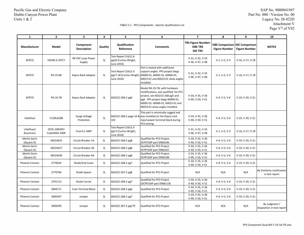
TABLE V‐1 ‐ PPS Components ‐ Seismic Qualification List
1 2 3 4 5 6 7 8 9 10
Manufacturer ModelComponent Description
QualityQualification
ReferenceComments
TRS Figure Number:OBE TRSSSE TRS
OBE Comparison Figure Number
SSE ComparisonFigure Number
NOTES
KEPCO HSF48‐3.1PFCT48 VDC Loop Power
SupplyQ
Test Report S1612.4 pg18 (Curtiss‐Wright, June 2016)
V‐31, V‐32, V‐33V‐46, V‐47, V‐48
V‐1, V‐2, V‐3 V‐16, V‐17, V‐18
KEPCO RA 19‐6B Kepco Rack Adaptor QTest Report S1612.4 pg17‐18 (Curtiss‐Wright, June 2016)
Part is tested with additional support angles. PPS project dwgs 60000‐01, 60005‐01, 60006‐01, 60023‐01 and 60024‐01 show angles installed.
V‐31, V‐32, V‐33V‐46, V‐47, V‐48
V‐1, V‐2, V‐3 V‐16, V‐17, V‐18
KEPCO RA 19‐7B Kepco Rack Adaptor Q 663222‐268‐2 pg6
Model RA‐19‐7B, with hardware modifications, was qualified for PCS project, see 663222‐268 pg5 and pg6. PPS project dwgs 60000‐01, 60005‐01, 60006‐01, 60023‐01 and 60024‐01 show angles installed.
V‐34, V‐35, V‐36V‐49, V‐50, V‐51
V‐4, V‐5, V‐6 V‐19, V‐20, V‐21
Littelfuse V130LA20BSurge Voltage
ProtectionQ
663222‐268‐2 page 16 &
102
This part is seismically rugged and was installed on the Kepco rack input power terminal block during PCS testing.
V‐34, V‐35, V‐36V‐49, V‐50, V‐51
V‐4, V‐5, V‐6 V‐19, V‐20, V‐21
Littelfuse/ Bussmann
0235.100HXP/ CodeGMA‐100R
Fuse 0.1 AMP QTest Report S1612.4 pg15 (Curtiss‐Wright, June 2016)
V‐31, V‐32, V‐33V‐46, V‐47, V‐48
V‐1, V‐2, V‐3 V‐16, V‐17, V‐18
Merlin Gerin (Square D)
MG24425 Circuit Breaker 1A Q 663222‐268‐2 pg8Qualified for PCS Project.DCPP/SAP part D966106.
V‐34, V‐35, V‐36V‐49, V‐50, V‐51
V‐4, V‐5, V‐6 V‐19, V‐20, V‐21
Merlin Gerin (Square D)
MG24427 Circuit Breaker 3A Q 663222‐268‐2 pg8Qualified for PCS Project.DCPP/SAP part D966107.
V‐34, V‐35, V‐36V‐49, V‐50, V‐51
V‐4, V‐5, V‐6 V‐19, V‐20, V‐21
Merlin Gerin (Square D)
MG24430 Circuit Breaker 6A Q 663222‐268‐2 pg8Qualified for PCS Project.DCPP/SAP part D966108.
V‐34, V‐35, V‐36V‐49, V‐50, V‐51
V‐4, V‐5, V‐6 V‐19, V‐20, V‐21
Phoenix Contact 2770024 Diode/End Cover Q 663222‐268‐2 pg7 Qualified for PCS ProjectV‐34, V‐35, V‐36V‐49, V‐50, V‐51
V‐4, V‐5, V‐6 V‐19, V‐20, V‐21
Phoenix Contact 2770794 Diode Spacer Q 663222‐267‐2 pg8 Qualified for PCS Project N/A N/A N/ABy Similarity Justification
in test report
Phoenix Contact 2791113 Diode Carrier Q 663222‐268‐2 pg7Qualified for PCS Project.(DCPP/SAP part D966119)
V‐34, V‐35, V‐36V‐49, V‐50, V‐51
V‐4, V‐5, V‐6 V‐19, V‐20, V‐21
Phoenix Contact 3004171 Fuse Terminal Block Q 663222‐268‐2 pg6 Qualified for PCS ProjectV‐34, V‐35, V‐36V‐49, V‐50, V‐51
V‐4, V‐5, V‐6 V‐19, V‐20, V‐21
Phoenix Contact 3005947 Jumper Q 663222‐268‐2 pg7 Qualified for PCS ProjectV‐34, V‐35, V‐36V‐49, V‐50, V‐51
V‐4, V‐5, V‐6 V‐19, V‐20, V‐21
Phoenix Contact 3009299 Jumper Q 663222‐267‐2 pg179 Qualified for PCS Project N/A N/A N/ABy Judgment /
Disposition in test report
PPS Component Qual Ref‐7‐14‐16‐ITK.xlsx
Pacific Gas and Electric Company Diablo Canyon Power Plant Units 1 & 2
SAP No. 9000041947 Part No. 000 / Version No. 00
Legacy No. IS-022D Attachment V
Page V7 of V82
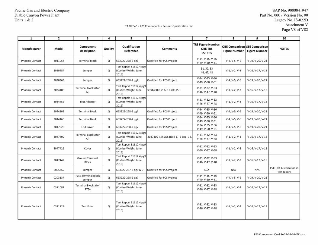
TABLE V‐1 ‐ PPS Components ‐ Seismic Qualification List
1 2 3 4 5 6 7 8 9 10
Manufacturer ModelComponent Description
QualityQualification
ReferenceComments
TRS Figure Number:OBE TRSSSE TRS
OBE Comparison Figure Number
SSE ComparisonFigure Number
NOTES
Phoenix Contact 3011054 Terminal Block Q 663222‐268‐2 pg6 Qualified for PCS ProjectV‐34, V‐35, V‐36V‐49, V‐50, V‐51
V‐4, V‐5, V‐6 V‐19, V‐20, V‐21
Phoenix Contact 3030284 Jumper QTest Report S1612.4 pg9 (Curtiss‐Wright, June 2016)
31, 32, 3346, 47, 48
V‐1, V‐2, V‐3 V‐16, V‐17, V‐18
Phoenix Contact 3030365 Jumper Q 663222‐268‐2 pg7 Qualified for PCS ProjectV‐34, V‐35, V‐36V‐49, V‐50, V‐51
V‐4, V‐5, V‐6 V‐19, V‐20, V‐21
Phoenix Contact 3034400Terminal Blocks (for
AI)Q
Test Report S1612.4 pg9 (Curtiss‐Wright, June 2016)
3034400 is in ALS Rack‐15.V‐31, V‐32, V‐33V‐46, V‐47, V‐48
V‐1, V‐2, V‐3 V‐16, V‐17, V‐18
Phoenix Contact 3034455 Test Adaptor QTest Report S1612.4 pg9 (Curtiss‐Wright, June 2016)
V‐31, V‐32, V‐33V‐46, V‐47, V‐48
V‐1, V‐2, V‐3 V‐16, V‐17, V‐18
Phoenix Contact 3044102 Terminal Block Q 663222‐268‐2 pg7 Qualified for PCS ProjectV‐34, V‐35, V‐36V‐49, V‐50, V‐51
V‐4, V‐5, V‐6 V‐19, V‐20, V‐21
Phoenix Contact 3044160 Terminal Block Q 663222‐268‐2 pg7 Qualified for PCS ProjectV‐34, V‐35, V‐36V‐49, V‐50, V‐51
V‐4, V‐5, V‐6 V‐19, V‐20, V‐21
Phoenix Contact 3047028 End Cover Q 663222‐268‐2 pg7 Qualified for PCS ProjectV‐34, V‐35, V‐36V‐49, V‐50, V‐51
V‐4, V‐5, V‐6 V‐19, V‐20, V‐21
Phoenix Contact 3047400Terminal Blocks (for
AI)Q
Test Report S1612.4 pg9 (Curtiss‐Wright, June 2016)
3047400 is in ALS Rack‐1, ‐6 and ‐12.V‐31, V‐32, V‐33V‐46, V‐47, V‐48
V‐1, V‐2, V‐3 V‐16, V‐17, V‐18
Phoenix Contact 3047426 Cover QTest Report S1612.4 pg9 (Curtiss‐Wright, June 2016)
V‐31, V‐32, V‐33V‐46, V‐47, V‐48
V‐1, V‐2, V‐3 V‐16, V‐17, V‐18
Phoenix Contact 3047442Ground Terminal
BlockQ
Test Report S1612.4 pg9 (Curtiss‐Wright, June 2016)
V‐31, V‐32, V‐33V‐46, V‐47, V‐48
V‐1, V‐2, V‐3 V‐16, V‐17, V‐18
Phoenix Contact 5025462 Jumper Q 663222‐267‐2 pg8 & 9 Qualified for PCS Project N/A N/A N/APull Test Justification in
test report
Phoenix Contact 0203137Fuse Terminal Block
JumperQ 663222‐268‐2 pg7 Qualified for PCS Project
V‐34, V‐35, V‐36V‐49, V‐50, V‐51
V‐4, V‐5, V‐6 V‐19, V‐20, V‐21
Phoenix Contact 0311087Terminal Blocks (for
RTD)Q
Test Report S1612.4 pg9 (Curtiss‐Wright, June 2016)
V‐31, V‐32, V‐33V‐46, V‐47, V‐48
V‐1, V‐2, V‐3 V‐16, V‐17, V‐18
Phoenix Contact 0311728 Test Point QTest Report S1612.4 pg9 (Curtiss‐Wright, June 2016)
V‐31, V‐32, V‐33V‐46, V‐47, V‐48
V‐1, V‐2, V‐3 V‐16, V‐17, V‐18
PPS Component Qual Ref‐7‐14‐16‐ITK.xlsx
Pacific Gas and Electric Company Diablo Canyon Power Plant Units 1 & 2
SAP No. 9000041947 Part No. 000 / Version No. 00
Legacy No. IS-022D Attachment V
Page V8 of V82

TABLE V‐1 ‐ PPS Components ‐ Seismic Qualification List
1 2 3 4 5 6 7 8 9 10
Manufacturer ModelComponent Description
QualityQualification
ReferenceComments
TRS Figure Number:OBE TRSSSE TRS
OBE Comparison Figure Number
SSE ComparisonFigure Number
NOTES
Phoenix Contact 0442079Ground Terminal
BlockQ
IS‐022B (9000040858) Sheet M‐55 & M‐56,RPE 8000004597
Part is also identified as USLKG 6N. In IS‐022B Att M (e.g., sheet M‐55), part is identified as "Ground terminal block to DIN rail" and shown at each end of ETP's (e.g., sheet M‐56).RPE 8*4597 Attachment 2 provides Invensys (Triconex) confirmation that this part was tested and qualified with the Triconex modules (i.e., FTP's/ETP's)..
V‐40, V‐41, V‐42V‐55, V‐56, V‐57
V‐10, V‐11, V‐12 V‐25, V‐26, V‐27
Phoenix Contact 0921011 Fuse Holder QTest Report S1612.4 pg14 (Curtiss‐Wright, June 2016)
V‐31, V‐32, V‐33V‐46, V‐47, V‐48
V‐1, V‐2, V‐3 V‐16, V‐17, V‐18
Pomona 2269‐2 Jack Banana Double Q See commentSeismically Qualified by analysis.DCPP/SAP part D955864.
See Attachment W for analysis.
Potter Brumfield 20C314 Relay Strap QIS‐022B (9000040858) Attachment Q (see comments)
Qualified by PCS project.Note: Relay strap part number 20C314 is not specifically called out in Att Q. This part is on PCS cabinet layout drawing 663222‐107 and is part of the standard mounting hardware for qualified part 27E121.
V‐37, V‐38, V‐39V‐52, V‐53, V‐54
V‐7, V‐8, V‐9 V‐22, V‐23, V‐24
Potter Brumfield 27E121 Relay Base QIS‐022B (9000040858) Sheet Q‐6
Qualified by PCS project.V‐37, V‐38, V‐39V‐52, V‐53, V‐54
V‐7, V‐8, V‐9 V‐22, V‐23, V‐24
Potter Brumfield KUP‐14D15‐24 Relay QIS‐022B (9000040858) Sheet Q‐6
Qualified by PCS project.V‐37, V‐38, V‐39V‐52, V‐53, V‐54
V‐7, V‐8, V‐9 V‐22, V‐23, V‐24
Potter Brumfield KUP‐14D15‐48 Relay Q See comment
Seismically qualified by similarity to tested relay model KUP‐14D15‐24. The coil rating (24VDC vs 48VDC) is the only difference.
V‐37, V‐38, V‐39V‐52, V‐53, V‐54
V‐7, V‐8, V‐9 V‐22, V‐23, V‐24See Attachment W for Similarity Justification
PPS Component Qual Ref‐7‐14‐16‐ITK.xlsx
Pacific Gas and Electric Company Diablo Canyon Power Plant Units 1 & 2
SAP No. 9000041947 Part No. 000 / Version No. 00
Legacy No. IS-022D Attachment V
Page V9 of V82
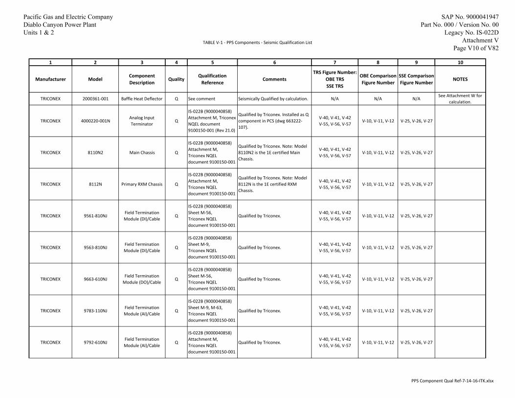
TABLE V‐1 ‐ PPS Components ‐ Seismic Qualification List
1 2 3 4 5 6 7 8 9 10
Manufacturer ModelComponent Description
QualityQualification
ReferenceComments
TRS Figure Number:OBE TRSSSE TRS
OBE Comparison Figure Number
SSE ComparisonFigure Number
NOTES
TRICONEX 2000361‐001 Baffle Heat Deflector Q See comment Seismically Qualified by calculation. N/A N/A N/ASee Attachment W for
calculation.
TRICONEX 4000220‐001NAnalog Input Terminator
Q
IS‐022B (9000040858) Attachment M, Triconex NQEL document 9100150‐001 (Rev 21.0)
Qualified by Triconex. Installed as Q
component in PCS (dwg 663222‐107).
V‐40, V‐41, V‐42V‐55, V‐56, V‐57
V‐10, V‐11, V‐12 V‐25, V‐26, V‐27
TRICONEX 8110N2 Main Chassis Q
IS‐022B (9000040858) Attachment M,Triconex NQEL document 9100150‐001
Qualified by Triconex. Note: Model 8110N2 is the 1E certified Main Chassis.
V‐40, V‐41, V‐42V‐55, V‐56, V‐57
V‐10, V‐11, V‐12 V‐25, V‐26, V‐27
TRICONEX 8112N Primary RXM Chassis Q
IS‐022B (9000040858) Attachment M,Triconex NQEL document 9100150‐001
Qualified by Triconex. Note: Model 8112N is the 1E certified RXM
Chassis.
V‐40, V‐41, V‐42V‐55, V‐56, V‐57
V‐10, V‐11, V‐12 V‐25, V‐26, V‐27
TRICONEX 9561‐810NJField Termination Module (DI)/Cable
Q
IS‐022B (9000040858) Sheet M‐56,Triconex NQEL document 9100150‐001
Qualified by Triconex.V‐40, V‐41, V‐42V‐55, V‐56, V‐57
V‐10, V‐11, V‐12 V‐25, V‐26, V‐27
TRICONEX 9563‐810NJField Termination Module (DI)/Cable
Q
IS‐022B (9000040858) Sheet M‐9, Triconex NQEL document 9100150‐001
Qualified by Triconex.V‐40, V‐41, V‐42V‐55, V‐56, V‐57
V‐10, V‐11, V‐12 V‐25, V‐26, V‐27
TRICONEX 9663‐610NJField Termination
Module (DO)/CableQ
IS‐022B (9000040858) Sheet M‐56,Triconex NQEL document 9100150‐001
Qualified by Triconex.V‐40, V‐41, V‐42V‐55, V‐56, V‐57
V‐10, V‐11, V‐12 V‐25, V‐26, V‐27
TRICONEX 9783‐110NJField Termination Module (AI)/Cable
Q
IS‐022B (9000040858) Sheet M‐9, M‐63,Triconex NQEL document 9100150‐001
Qualified by Triconex.V‐40, V‐41, V‐42V‐55, V‐56, V‐57
V‐10, V‐11, V‐12 V‐25, V‐26, V‐27
TRICONEX 9792‐610NJField Termination Module (AI)/Cable
Q
IS‐022B (9000040858) Attachment M,Triconex NQEL document 9100150‐001
Qualified by Triconex.V‐40, V‐41, V‐42V‐55, V‐56, V‐57
V‐10, V‐11, V‐12 V‐25, V‐26, V‐27
PPS Component Qual Ref‐7‐14‐16‐ITK.xlsx
Pacific Gas and Electric Company Diablo Canyon Power Plant Units 1 & 2
SAP No. 9000041947 Part No. 000 / Version No. 00
Legacy No. IS-022D Attachment V
Page V10 of V82

TABLE V‐1 ‐ PPS Components ‐ Seismic Qualification List
1 2 3 4 5 6 7 8 9 10
Manufacturer ModelComponent Description
QualityQualification
ReferenceComments
TRS Figure Number:OBE TRSSSE TRS
OBE Comparison Figure Number
SSE ComparisonFigure Number
NOTES
TRICONEX 9860‐610NJField Termination
Module (AO)/CableQ
IS‐022B (9000040858) Sheet M‐9, M‐63,Triconex NQEL document 9100150‐001
Qualified by Triconex.V‐40, V‐41, V‐42V‐55, V‐56, V‐57
V‐10, V‐11, V‐12 V‐25, V‐26, V‐27
Weidmuller 1061200000 End Bracket Q
Test Procedure S1612.0 pg132 (Curtiss‐Wright, April 2016) Test Report S1612.4 pgs 5 and 9 (Curtiss‐Wright, June 2016)
Part is also identified as "WEW
35/2" by manufacturer. Test Report S1612.4 pg9 only identifies this part as "Weidmuller DIN rail stops".
V‐31, V‐32, V‐33V‐46, V‐47, V‐48
V‐1, V‐2, V‐3 V‐16, V‐17, V‐18
Westinghouse 2100‐00001‐0 Dataforth Isolator QTest Report S1612.4 pg16 (Curtiss‐Wright, June 2016)
Part is also identified as DSCA32‐01C.
V‐31, V‐32, V‐33V‐46, V‐47, V‐48
V‐1, V‐2, V‐3 V‐16, V‐17, V‐18
WestinghouseTable 1 of dwg 926240‐1, ‐6, ‐12 and ‐15 Sht 2
Advance Logic System
(ALS)Q
Westinghouse reports:EQLR‐224B and 6116‐00204
Qualified by Westinghouse.V‐43, V‐44, V‐45V‐58, V‐59, V‐60
V‐13, V‐14, V‐15 V‐28, V‐29, V‐30
WestinghouseTable 2 of dwg 926240‐1, ‐6, ‐12 and ‐15 Sht 2
Advance Logic System
(ALS)Q
Westinghouse reports:EQLR‐224B and 6116‐00204
Qualified by Westinghouse.V‐43, V‐44, V‐45V‐58, V‐59, V‐60
V‐13, V‐14, V‐15 V‐28, V‐29, V‐30
WestinghouseLine Sense Module
(LSM)Q
Westinghouse reportEQ‐QR‐120‐PGE
Qualified by Westinghouse.V‐45a, V‐45bV‐60a, V‐60b
V‐15a, V‐15b,V‐15c
V‐30a, V‐30b,V‐30c
PPS Component Qual Ref‐7‐14‐16‐ITK.xlsx
Pacific Gas and Electric Company Diablo Canyon Power Plant Units 1 & 2
SAP No. 9000041947 Part No. 000 / Version No. 00
Legacy No. IS-022D Attachment V
Page V11 of V82

PPS Components ‐ Seismic Qualification List
Reference Number
Reference Document IDDocument Revision
Document Title or DescriptionDCPP
Document Type
Comments
V‐1 663222‐267 2NLI Qualification Report QR‐01913272‐1
(Rev. 5, November 2011)RPT
DCPP Record Management System (RMS) Record Location (RLOC): 90037‐4354.Report was issued for previously completed PCS Upgrade project.
V‐2 663222‐268 2NLI Supplemental Qualification Report SQR‐
01913272‐1 (Rev. 3, May 2012)RPT
DCPP RMS RLOC: 90037‐8082.Report was issued for previously completed PCS Upgrade project.
V‐36116‐00204 (Westinghouse
Report)2 (July 2015)
Diablo Canyon Process Protection System, ALS Subsystem Equipment Qualification
Evaluationn/a This Westinghouse report was not found in the DCPP
controlled document databases (RMS, Filenet, etc.).
V‐4EQLR‐224B (Westinghouse
Report)1 (April 2012)
Seismic Test Report for the Advanced Logic System (ALS)
n/a This Westinghouse report was not found in the DCPP controlled document databases (RMS, Filenet, etc.).
V‐5 IS‐022B (9000040858) 0Seismic Qualification of Process Control
System (PCS), Replacement of Westinghouse 7100 Process Control Racks
CALC
Calculation issued for previously completed PCS Upgrade project.Attachment M of IS‐022B is draft NTS Report TR62987‐07N‐SEI (Rev. 0 draft dated April 11, 2007) for qualification of Triconex equipment. Final report is proprietary per the note on sheet 3 of IS‐022B.Attachment Q of IS‐022B is Farwell & Hendricks report 60162 for qualification of Potter & Brumfield relay.
V‐6 8000004597 0
Replacement or New Part Evaluation (RPE), Subject: Ground terminal blocks used as end
blocks with the Triconex field termination panels (FTP) …
RPEDCPP RMS RLOC: 90021‐5094.RPE for Phoenix Contact Ground Terminal Block part USLKG‐6N (0442079).
V‐7 SAPN 50849571 Task 4 n/a Track PPS Project Engineering Tasks ‐ Evaluate Switch Similarity n/a
Used to establish Similarity of Switches 7804K33 and 8837K4 with the tested switches 7700K2 and 7560K5 respectively.
V‐8 NOT USED
V‐9 S1100.0 (9000041788) 0Seismic Qualification Analysis Report for
Seismically Insensitive ItemsDCA DCPP RMS RLOC: Not found.
V‐10 NOT USED
V‐11 S1612.0 0Curtiss‐Wright Seismic Qualification Test
Report for Multiple Itemsn/a
Test report for DCPP PPS components tested in April 2016. Report Rev0 dated 5/25/16.
V‐12 6010908‐413 1Eagle 21 Standard Cabinet Base Assembly
and Mounting DetailsDWG
V‐13 6010908‐414 1Eagle 21 Standard Cabinet Base Assembly
and Mounting DetailsDWG
V‐14 6010908‐415 1Eagle 21 Standard Cabinet Base Assembly
and Mounting DetailsDWG
V‐15 1000000237 1Replace Westinghouse Hagan 7100 Process
Control System (PCS)DCP
This Design Change Package installed Tricon equipment for the PCS. Attachment M of the DCP is Tricon v10 Nuclear Qualified Equipment List (NQEL) 9100150‐001 Rev11. Attachment N of the DCP is Triconex Equipment Qualification Summary Report 9600164‐545 Rev3.
V‐15a Tricon v10 NQEL 9100150‐001 11 (02/2011) Attachment M to DCP 1000000237 DCP
V‐15bTricon v10 NQEL 9100150‐001
(‐NP)21 (02/2016)
Tricon v10 Nuclear Qualified Equipment List (NQEL)
n/a Non‐Proprietary Vendor Document
V‐15c Tricon v10 9600164‐545 3 Attachment N to DCP 1000000237 DCP
V‐16 ES‐33 (9000012805) 10 Seismic Qualification of POV1 and POV2 CALCDCPP RMS RLOC: 90018‐1439.Attachment 35 of ES‐33 is Triconex Seismic Test Report 9600164‐526.
V‐17 NOT USED
V‐18 S1612.0 0Curtiss‐Wright Seismic Qualification Test
Procedure for Multiple Itemsn/a
Test Procedure for DCPP PPS components tested in April 2016.
V‐19Baffle Heat Deflector (email
and dwg)2/23/2016
Subject: FW:PG&E Request ‐ Baffle Heat Deflector, Attachment: Baffle_2000361.pdf
n/aWeight and drawing for Triconex part 2000361‐001.
V‐20 S1612.4 (9000041984) 0Curtiss‐Wright Seismic Qualification Test
Report for Multiple Itemsn/a
Test Report for DCPP PPS components tested in June 2016.
V‐21 DIT‐50831673‐001 1Design Input Transmittal, Subject: Process
Protection System design and layoutDIT
Includes PPS rack structural drawings and panel arrangement drawings that include bill‐of‐materials.
V‐22 EQ‐QR‐120‐PGE 1 (July 2015)Advanced Logic System and Line Sense
Module Equipment Qualification Summary Report
n/a This Westinghouse report was not found in the DCPP controlled document databases (RMS, Filenet, etc.).
8/1/2016 Page 1 of 1 PPS Component Qual Ref‐7‐14‐16‐ITK.xlsx
Pacific Gas and Electric Company Diablo Canyon Power Plant Units 1 & 2
SAP No. 9000041947 Part No. 000 / Version No. 00
Legacy No. IS-022D Attachment V
Page V12 of V82

1 10 100Frequency (Hz)
0
5
10
15
20
Acc
eler
atio
n(g
)
TRS - Curtiss WrightDE 2 IERS ENV
Figure V-1: OBE Front to Back 5% Damping (S1612.4 (9000041984-000-00), Reference V-20).
Pacific Gas and Electric Company Diablo Canyon Power Plant Units 1 & 2
SAP No. 9000041947 Part No. 000 / Version No. 00
Legacy No. IS-022D Attachment V
Page V13 of V82

1 10 100Frequency (Hz)
0
5
10
15
20
Acc
eler
atio
n(g
)
TRS - Curtiss WrightDE 2 IERS ENV
Figure V-2: OBE Side to Side 5% Damping (S1612.4 (9000041984-000-00), Reference V-20).
Pacific Gas and Electric Company Diablo Canyon Power Plant Units 1 & 2
SAP No. 9000041947 Part No. 000 / Version No. 00
Legacy No. IS-022D Attachment V
Page V14 of V82
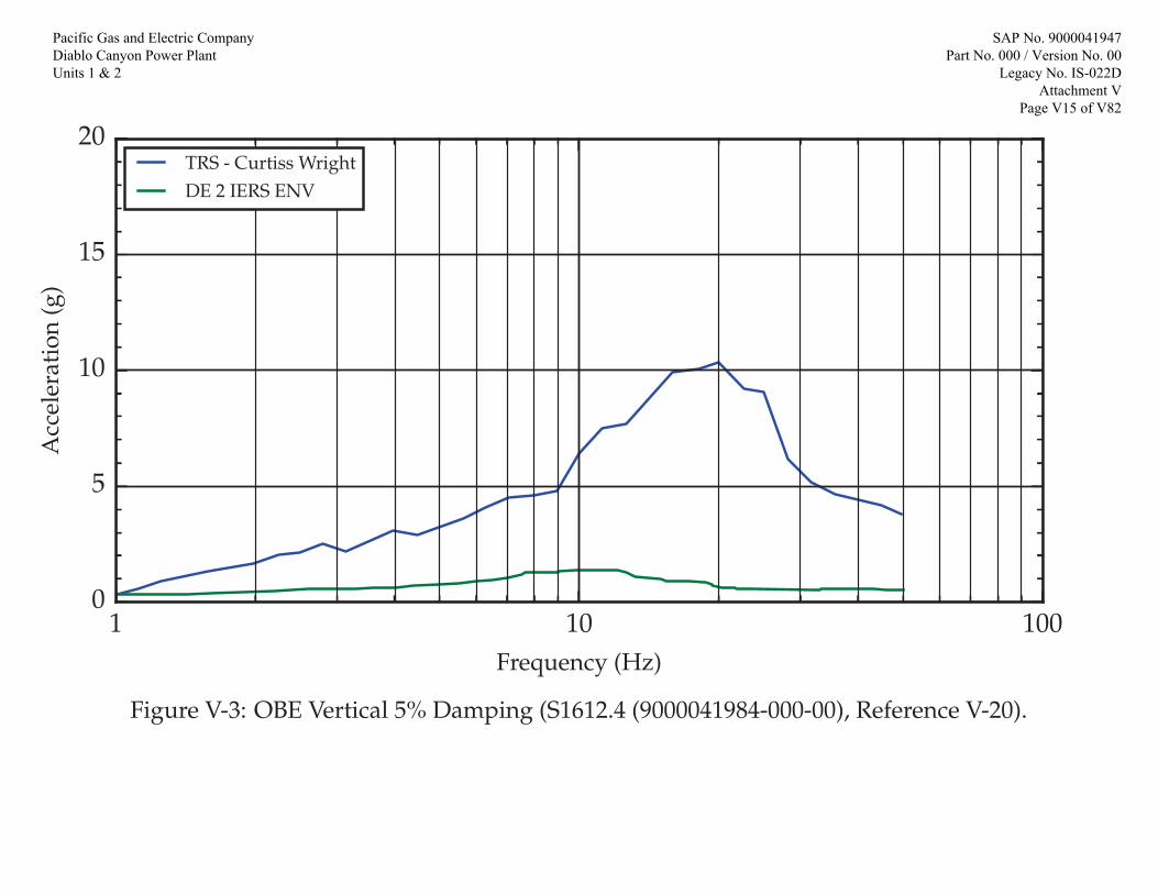
1 10 100Frequency (Hz)
0
5
10
15
20
Acc
eler
atio
n(g
)
TRS - Curtiss WrightDE 2 IERS ENV
Figure V-3: OBE Vertical 5% Damping (S1612.4 (9000041984-000-00), Reference V-20).
Pacific Gas and Electric Company Diablo Canyon Power Plant Units 1 & 2
SAP No. 9000041947 Part No. 000 / Version No. 00
Legacy No. IS-022D Attachment V
Page V15 of V82

1 10 100Frequency (Hz)
0
5
10
15
20
Acc
eler
atio
n(g
)
TRS - NLIDE 1 IERS ENV
Figure V-4: OBE Front to Back 4% Damping (663222-268, Reference V-2).
Pacific Gas and Electric Company Diablo Canyon Power Plant Units 1 & 2
SAP No. 9000041947 Part No. 000 / Version No. 00
Legacy No. IS-022D Attachment V
Page V16 of V82
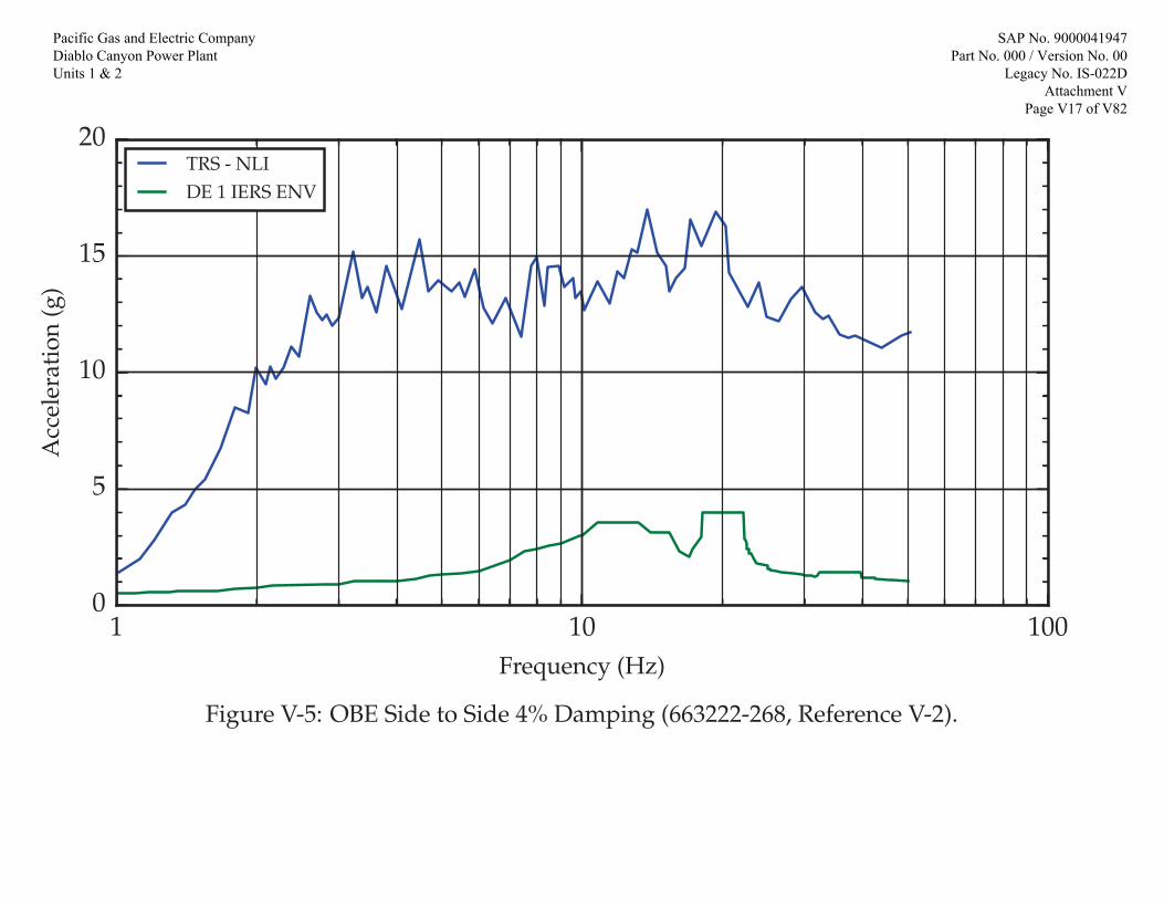
1 10 100Frequency (Hz)
0
5
10
15
20
Acc
eler
atio
n(g
)
TRS - NLIDE 1 IERS ENV
Figure V-5: OBE Side to Side 4% Damping (663222-268, Reference V-2).
Pacific Gas and Electric Company Diablo Canyon Power Plant Units 1 & 2
SAP No. 9000041947 Part No. 000 / Version No. 00
Legacy No. IS-022D Attachment V
Page V17 of V82

1 10 100Frequency (Hz)
0
5
10
15
20
25
30
Acc
eler
atio
n(g
)
TRS - NLIDE 1 IERS ENV
Figure V-6: OBE Vertical 4% Damping (663222-268, Reference V-2).
Pacific Gas and Electric Company Diablo Canyon Power Plant Units 1 & 2
SAP No. 9000041947 Part No. 000 / Version No. 00
Legacy No. IS-022D Attachment V
Page V18 of V82

1 10 100Frequency (Hz)
0
5
10
15
20
Acc
eler
atio
n(g
)
TRS - PBDE - PB IERS ENV
Figure V-7: Potter Brumfield OBE Front to Back 5% Damping (IS-022B - Attachment Q, Reference V-5).
Pacific Gas and Electric Company Diablo Canyon Power Plant Units 1 & 2
SAP No. 9000041947 Part No. 000 / Version No. 00
Legacy No. IS-022D Attachment V
Page V19 of V82

1 10 100Frequency (Hz)
0
2
4
6
8
10
Acc
eler
atio
n(g
)
TRS - PBDE - PB IERS ENV
Figure V-8: Potter Brumfield OBE Side to Side 5% Damping (IS-022B - Attachment Q, Reference V-5).
Pacific Gas and Electric Company Diablo Canyon Power Plant Units 1 & 2
SAP No. 9000041947 Part No. 000 / Version No. 00
Legacy No. IS-022D Attachment V
Page V20 of V82
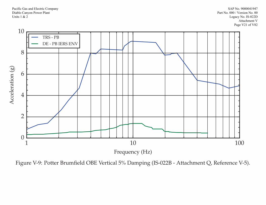
1 10 100Frequency (Hz)
0
2
4
6
8
10
Acc
eler
atio
n(g
)
TRS - PBDE - PB IERS ENV
Figure V-9: Potter Brumfield OBE Vertical 5% Damping (IS-022B - Attachment Q, Reference V-5).
Pacific Gas and Electric Company Diablo Canyon Power Plant Units 1 & 2
SAP No. 9000041947 Part No. 000 / Version No. 00
Legacy No. IS-022D Attachment V
Page V21 of V82

1 10 100Frequency (Hz)
0
5
10
15
20
Acc
eler
atio
n(g
)
TRS - NTSDE - TRI IERS ENV
Figure V-10: Tricon OBE Front to Back 5% Damping (IS-022B - Attachment M, Reference V-5).
Pacific Gas and Electric Company Diablo Canyon Power Plant Units 1 & 2
SAP No. 9000041947 Part No. 000 / Version No. 00
Legacy No. IS-022D Attachment V
Page V22 of V82

1 10 100Frequency (Hz)
0
5
10
15
20
Acc
eler
atio
n(g
)
TRS - NTSDE - TRI IERS ENV
Figure V-11: Tricon OBE Side to Side 5% Damping (IS-022B - Attachment M, Reference V-5).
Pacific Gas and Electric Company Diablo Canyon Power Plant Units 1 & 2
SAP No. 9000041947 Part No. 000 / Version No. 00
Legacy No. IS-022D Attachment V
Page V23 of V82

1 10 100Frequency (Hz)
0
5
10
15
20
Acc
eler
atio
n(g
)
TRS - NTSDE - TRI IERS ENV
Figure V-12: Tricon OBE Vertical 5% Damping (IS-022B - Attachment M, Reference V-5).
Pacific Gas and Electric Company Diablo Canyon Power Plant Units 1 & 2
SAP No. 9000041947 Part No. 000 / Version No. 00
Legacy No. IS-022D Attachment V
Page V24 of V82

1 10 100Frequency (Hz)
0
5
10
15
20
25
30
35
40
Acc
eler
atio
n(g
)
TRS - WestinghouseDE 2 IERS ENV
Figure V-13: OBE Front to Back 5% Damping (EQLR-224B, Reference V-4).
Pacific Gas and Electric Company Diablo Canyon Power Plant Units 1 & 2
SAP No. 9000041947 Part No. 000 / Version No. 00
Legacy No. IS-022D Attachment V
Page V25 of V82

1 10 100Frequency (Hz)
0
5
10
15
20
25
30
35
40
Acc
eler
atio
n(g
)
TRS - WestinghouseDE 2 IERS ENV
Figure V-14: OBE Side to Side 5% Damping (EQLR-224B, Reference V-4).
Pacific Gas and Electric Company Diablo Canyon Power Plant Units 1 & 2
SAP No. 9000041947 Part No. 000 / Version No. 00
Legacy No. IS-022D Attachment V
Page V26 of V82

1 10 100Frequency (Hz)
0
5
10
15
20
Acc
eler
atio
n(g
)
TRS - WestinghouseDE 2 IERS ENV
Figure V-15: OBE Vertical 5% Damping (EQLR-224B, Reference V-4).
Pacific Gas and Electric Company Diablo Canyon Power Plant Units 1 & 2
SAP No. 9000041947 Part No. 000 / Version No. 00
Legacy No. IS-022D Attachment V
Page V27 of V82

1 10 1000
5
10
15
20
Acc
eler
atio
n(g
)
LSM OBE TRS HOR (SS-FB)DE 2 IERS ALS LSM ENV
Frequency (Hz)
Figure V-15a: ALS LSM OBE 5% Damping (EQ-QR-120-PGE, Reference V-22)
Pacific Gas and Electric Company Diablo Canyon Power Plant Units 1 & 2
SAP No. 9000041947 Part No. 000 / Version No. 00
Legacy No. IS-022D Attachment V
Page V28 of V82

1 10 1000
5
10
15
20
Acc
eler
atio
n(g
)
LSM OBE TRS HOR (SS-FB)DE 2 IERS ALS LSM ENV
Frequency (Hz)
Figure V-15b: ALS LSM OBE 5% Damping (EQ-QR-120-PGE, Reference V-22)
Pacific Gas and Electric Company Diablo Canyon Power Plant Units 1 & 2
SAP No. 9000041947 Part No. 000 / Version No. 00
Legacy No. IS-022D Attachment V
Page V29 of V82

1 10 100Frequency (Hz)
0
5
10
15
20
Acc
eler
atio
n(g
)
LSM OBE TRS VERTDE 2 IERS ALS LSM ENV
Figure V-15c: ALS LSM OBE Vertical 5% Damping (EQ-QR-120-PGE, Reference V-22)
Pacific Gas and Electric Company Diablo Canyon Power Plant Units 1 & 2
SAP No. 9000041947 Part No. 000 / Version No. 00
Legacy No. IS-022D Attachment V
Page V30 of V82

1 10 100Frequency (Hz)
0
5
10
15
20
25
30
Acc
eler
atio
n(g
)
TRS - Curtiss WrightDDE 2 IERS ENVHosgri 2 IERS ENV
Figure V-16: SSE Front to Back 5% Damping (S1612.4 (9000041984-000-00), Reference V-20).
Pacific Gas and Electric Company Diablo Canyon Power Plant Units 1 & 2
SAP No. 9000041947 Part No. 000 / Version No. 00
Legacy No. IS-022D Attachment V
Page V31 of V82
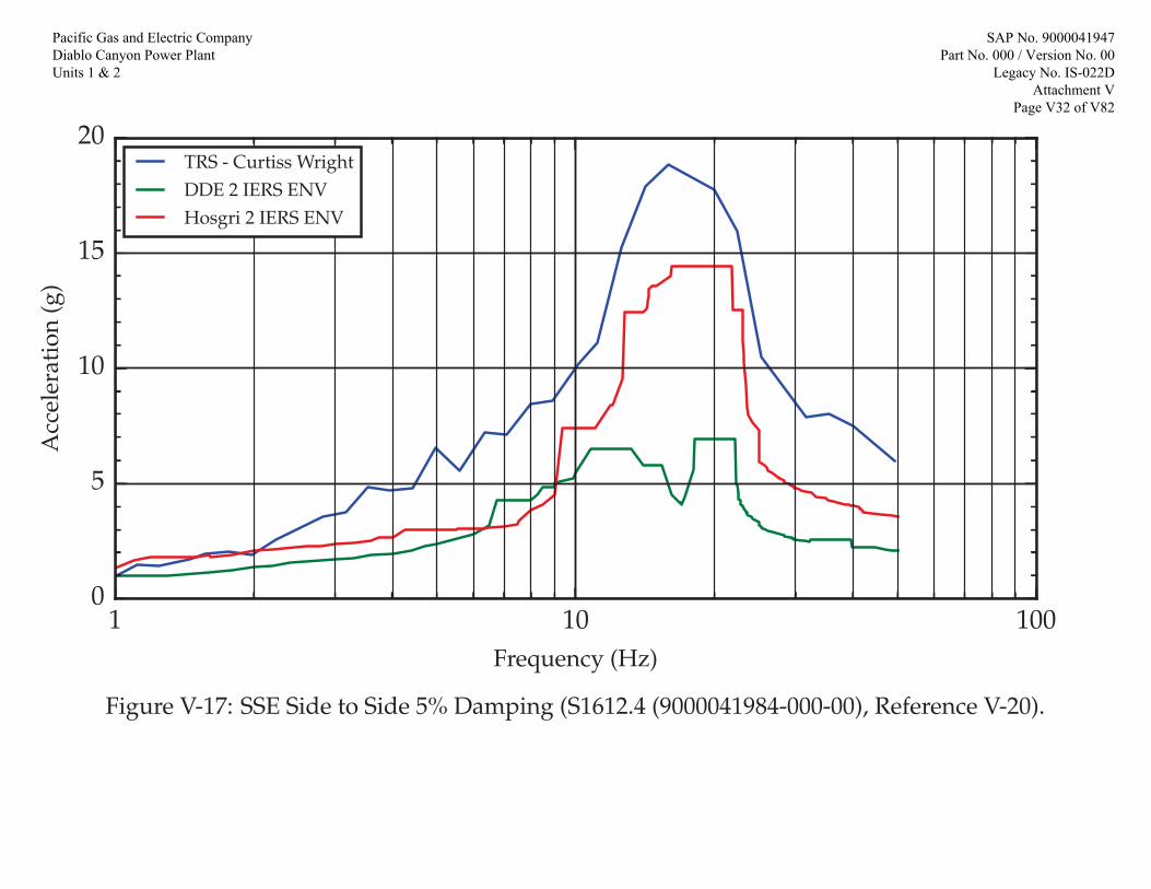
1 10 100Frequency (Hz)
0
5
10
15
20
Acc
eler
atio
n(g
)
TRS - Curtiss WrightDDE 2 IERS ENVHosgri 2 IERS ENV
Figure V-17: SSE Side to Side 5% Damping (S1612.4 (9000041984-000-00), Reference V-20).
Pacific Gas and Electric Company Diablo Canyon Power Plant Units 1 & 2
SAP No. 9000041947 Part No. 000 / Version No. 00
Legacy No. IS-022D Attachment V
Page V32 of V82

1 10 100Frequency (Hz)
0
5
10
15
20
Acc
eler
atio
n(g
)
TRS - Curtiss WrightDDE 2 IERS ENVHosgri 2 IERS ENV
Figure V-18: SSE Vertical 5% Damping (S1612.4 (9000041984-000-00), Reference V-20).
Pacific Gas and Electric Company Diablo Canyon Power Plant Units 1 & 2
SAP No. 9000041947 Part No. 000 / Version No. 00
Legacy No. IS-022D Attachment V
Page V33 of V82

1 10 100Frequency (Hz)
0
5
10
15
20
25
30
35
40
Acc
eler
atio
n(g
)
TRS - NLIDDE 1 IERS ENVHosgri 1 IERS ENV (-15% +5% widened)
Figure V-19: SSE Front to Back 4% Damping (663222-268, Reference V-2).
Pacific Gas and Electric Company Diablo Canyon Power Plant Units 1 & 2
SAP No. 9000041947 Part No. 000 / Version No. 00
Legacy No. IS-022D Attachment V
Page V34 of V82

1 10 100Frequency (Hz)
0
5
10
15
20
25
30
35
40
Acc
eler
atio
n(g
)
TRS - NLIDDE 1 IERS ENVHosgri 1 IERS ENV
Figure V-20: SSE Side to Side 4% Damping (663222-268, Reference V-2).
Pacific Gas and Electric Company Diablo Canyon Power Plant Units 1 & 2
SAP No. 9000041947 Part No. 000 / Version No. 00
Legacy No. IS-022D Attachment V
Page V35 of V82

1 10 100Frequency (Hz)
0
5
10
15
20
25
30
35
40
Acc
eler
atio
n(g
)
TRS - NLIDDE 1 IERS ENVHosgri 1 IERS ENV
Figure V-21: SSE Vertical 4% Damping (663222-268, Reference V-2).
Pacific Gas and Electric Company Diablo Canyon Power Plant Units 1 & 2
SAP No. 9000041947 Part No. 000 / Version No. 00
Legacy No. IS-022D Attachment V
Page V36 of V82

1 10 100Frequency (Hz)
0
5
10
15
20
Acc
eler
atio
n(g
)
TRS - PBDDE - PB IERS ENVHosgri - PB IERS ENV
Figure V-22: Potter Brumfield SSE Front to Back 5% Damping (IS-022B - Attachment Q, Reference V-5).
Pacific Gas and Electric Company Diablo Canyon Power Plant Units 1 & 2
SAP No. 9000041947 Part No. 000 / Version No. 00
Legacy No. IS-022D Attachment V
Page V37 of V82
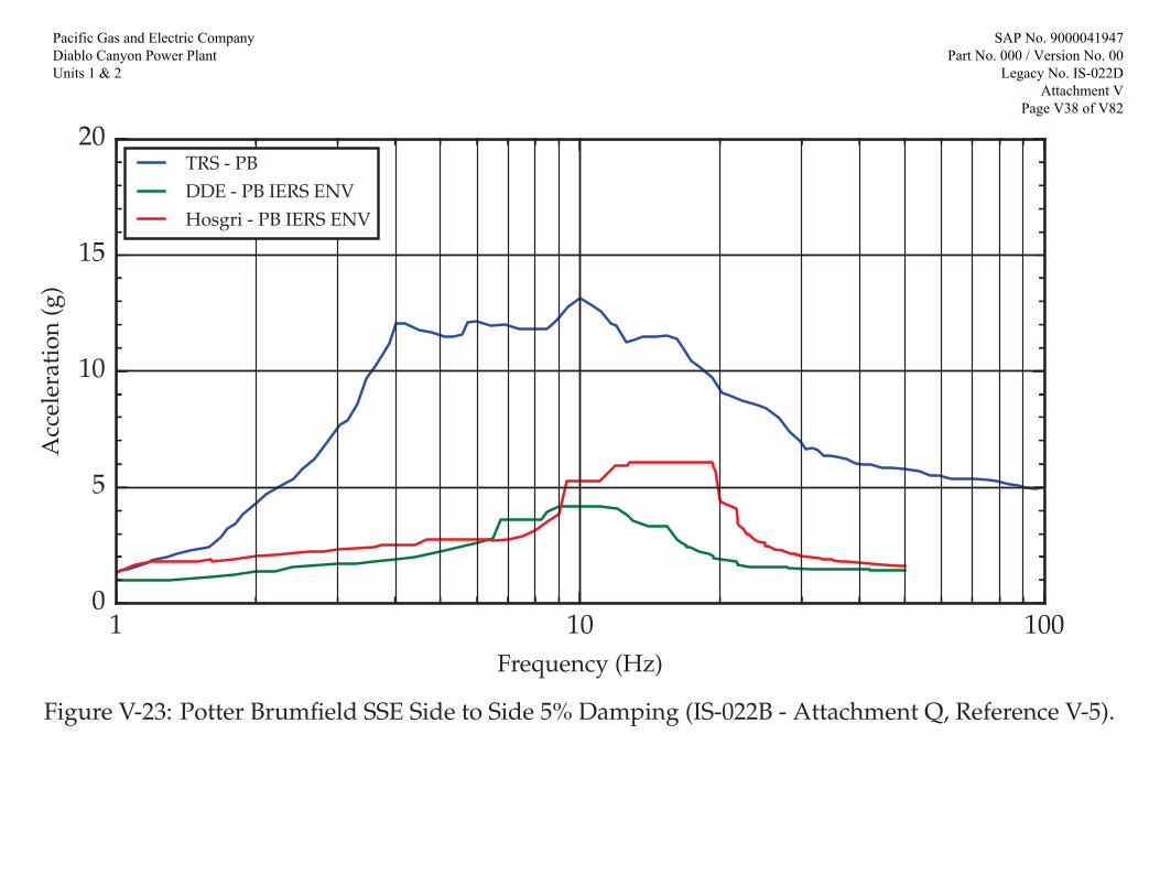
1 10 100Frequency (Hz)
0
5
10
15
20
Acc
eler
atio
n(g
)
TRS - PBDDE - PB IERS ENVHosgri - PB IERS ENV
Figure V-23: Potter Brumfield SSE Side to Side 5% Damping (IS-022B - Attachment Q, Reference V-5).
Pacific Gas and Electric Company Diablo Canyon Power Plant Units 1 & 2
SAP No. 9000041947 Part No. 000 / Version No. 00
Legacy No. IS-022D Attachment V
Page V38 of V82

1 10 100Frequency (Hz)
0
5
10
15
20
Acc
eler
atio
n(g
)
TRS - PBDDE - PB IERS ENVHosgri - PB IERS ENV
Figure V-24: Potter Brumfield SSE Vertical 5% Damping (IS-022B - Attachment Q, Reference V-5).
Pacific Gas and Electric Company Diablo Canyon Power Plant Units 1 & 2
SAP No. 9000041947 Part No. 000 / Version No. 00
Legacy No. IS-022D Attachment V
Page V39 of V82
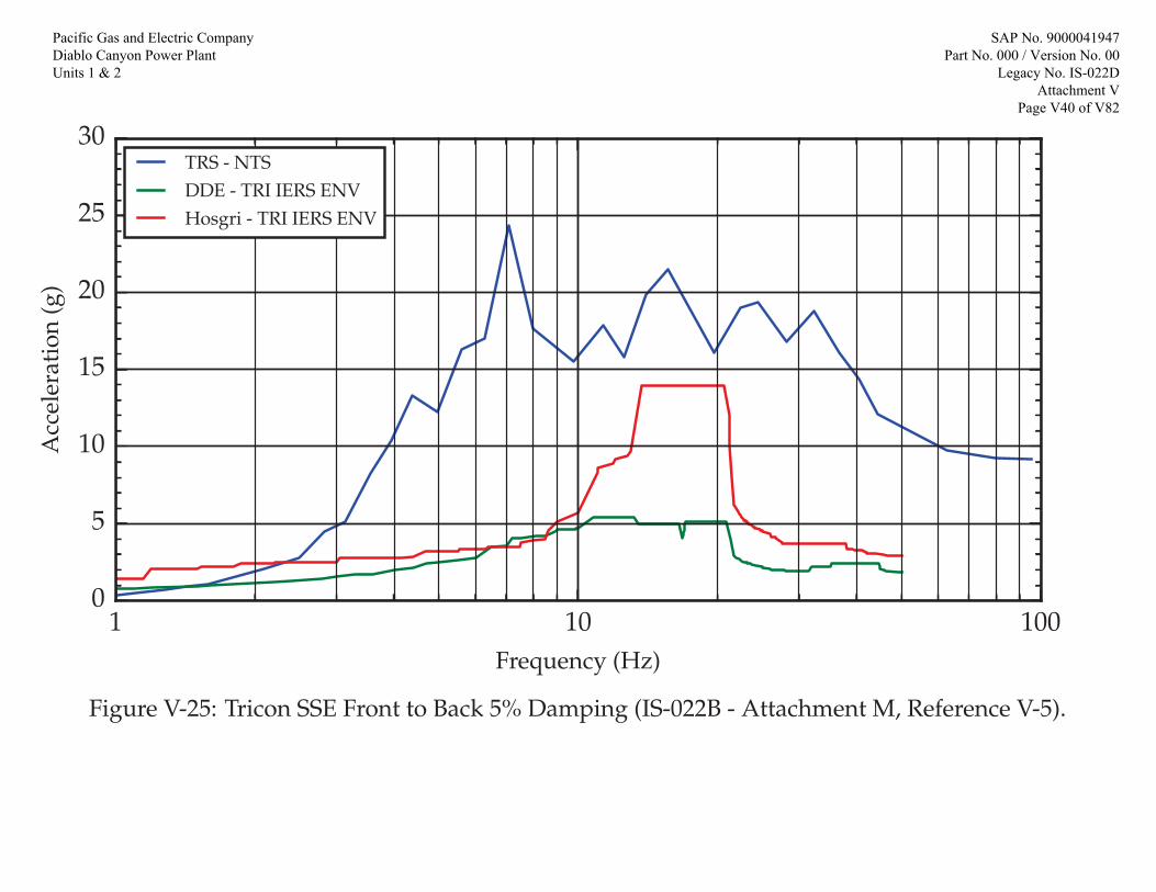
1 10 100Frequency (Hz)
0
5
10
15
20
25
30
Acc
eler
atio
n(g
)
TRS - NTSDDE - TRI IERS ENVHosgri - TRI IERS ENV
Figure V-25: Tricon SSE Front to Back 5% Damping (IS-022B - Attachment M, Reference V-5).
Pacific Gas and Electric Company Diablo Canyon Power Plant Units 1 & 2
SAP No. 9000041947 Part No. 000 / Version No. 00
Legacy No. IS-022D Attachment V
Page V40 of V82

1 10 100Frequency (Hz)
0
5
10
15
20
25
30
Acc
eler
atio
n(g
)
TRS - NTSDDE - TRI IERS ENVHosgri - TRI IERS ENV
Figure V-26: Tricon SSE Side to Side 5% Damping (IS-022B - Attachment M, Reference V-5).
Pacific Gas and Electric Company Diablo Canyon Power Plant Units 1 & 2
SAP No. 9000041947 Part No. 000 / Version No. 00
Legacy No. IS-022D Attachment V
Page V41 of V82
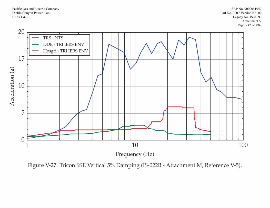
1 10 100Frequency (Hz)
0
5
10
15
20
Acc
eler
atio
n(g
)
TRS - NTSDDE - TRI IERS ENVHosgri - TRI IERS ENV
Figure V-27: Tricon SSE Vertical 5% Damping (IS-022B - Attachment M, Reference V-5).
Pacific Gas and Electric Company Diablo Canyon Power Plant Units 1 & 2
SAP No. 9000041947 Part No. 000 / Version No. 00
Legacy No. IS-022D Attachment V
Page V42 of V82

1 10 100Frequency (Hz)
0
10
20
30
40
50
60
Acc
eler
atio
n(g
)
TRS -WestinghouseDDE 2 IERS ENVHosgri 2 IERS ENV
Figure V-28: SSE Front to Back 5% Damping (EQLR-224B, Reference V-4).
Pacific Gas and Electric Company Diablo Canyon Power Plant Units 1 & 2
SAP No. 9000041947 Part No. 000 / Version No. 00
Legacy No. IS-022D Attachment V
Page V43 of V82

1 10 100Frequency (Hz)
0
10
20
30
40
50
60
Acc
eler
atio
n(g
)
TRS -WestinghouseDDE 2 IERS ENVHosgri 2 IERS ENV
Figure V-29: SSE Side to Side 5% Damping (EQLR-224B, Reference V-4).
Pacific Gas and Electric Company Diablo Canyon Power Plant Units 1 & 2
SAP No. 9000041947 Part No. 000 / Version No. 00
Legacy No. IS-022D Attachment V
Page V44 of V82

1 10 100Frequency (Hz)
0
5
10
15
20
25
30
Acc
eler
atio
n(g
)
TRS -WestinghouseDDE 2 IERS ENVHosgri 2 IERS ENV
Figure V-30: SSE Vertical 5% Damping (EQLR-224B, Reference V-4).
Pacific Gas and Electric Company Diablo Canyon Power Plant Units 1 & 2
SAP No. 9000041947 Part No. 000 / Version No. 00
Legacy No. IS-022D Attachment V
Page V45 of V82

1 10 1000
5
10
15
20
25
30
35
40
Acc
eler
atio
n(g
)
LSM SSE TRS HOR (SS-FB)DDE 2 IERS ALS LSM ENVHosgri IERS ALS LSM ENV
Frequency (Hz)
Figure V-30a: ALS LSM SSE 5% Damping (EQ-QR-120-PGE, Reference V-22)
Pacific Gas and Electric Company Diablo Canyon Power Plant Units 1 & 2
SAP No. 9000041947 Part No. 000 / Version No. 00
Legacy No. IS-022D Attachment V
Page V46 of V82

1 10 1000
5
10
15
20
25
30
35
40
Acc
eler
atio
n(g
)
LSM SSE TRS HOR (SS-FB)DDE 2 IERS ALS LSM ENVHosgri IERS ALS LSM ENV
Frequency (Hz)
Figure V-30b: ALS LSM SSE 5% Damping (EQ-QR-120-PGE, Reference V-22)
Pacific Gas and Electric Company Diablo Canyon Power Plant Units 1 & 2
SAP No. 9000041947 Part No. 000 / Version No. 00
Legacy No. IS-022D Attachment V
Page V47 of V82
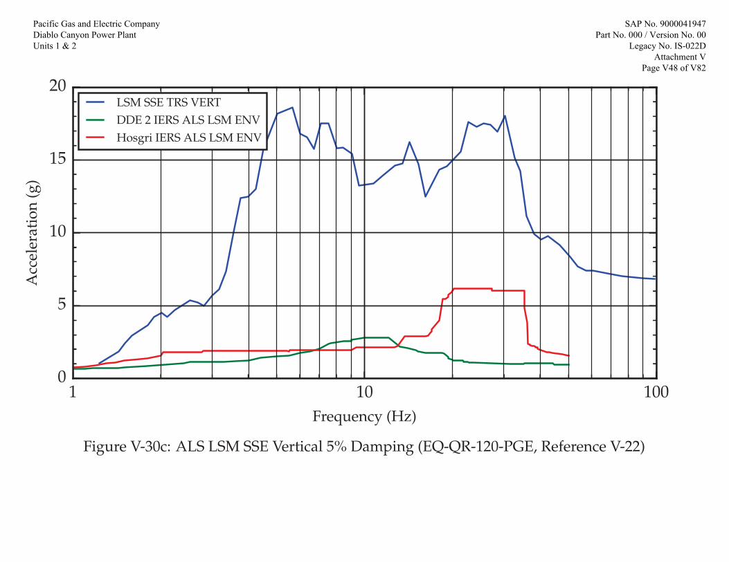
1 10 100Frequency (Hz)
0
5
10
15
20
Acc
eler
atio
n(g
)
LSM SSE TRS VERTDDE 2 IERS ALS LSM ENVHosgri IERS ALS LSM ENV
Figure V-30c: ALS LSM SSE Vertical 5% Damping (EQ-QR-120-PGE, Reference V-22)
Pacific Gas and Electric Company Diablo Canyon Power Plant Units 1 & 2
SAP No. 9000041947 Part No. 000 / Version No. 00
Legacy No. IS-022D Attachment V
Page V48 of V82

Pacific Gas and Electric Company Diablo Canyon Power Plant Units 1 & 2

Purpose:The purpose of this evaluation is to document the seismic qualification of the following components for use inPPS Cabinets at Diablo Canyon Power Plant.
Bussmann Glass Tube Fuses AGC-1, AGC-1/2, and AGC 2-1/21.Pomona Electronics Model 2269 Insulated Double Banana Jacks2.Tricon Baffle Heat Deflector, Drawing 2000361-0013.Potter & Brumfield Relay Model KUP-14D15-484.
1. Seismic Qualification of Bussmann AGC-1, AGC 1/2, & AGC 2-1/2 Fuses
Component geometry/configuration and mounting details per Ref. W-1 (see page W10).
The Bussmann AGC series fuses are the typical ferrule-type fuses with a filament. The AGC series partnumbers range from AGC-1/4 to AGC-40 and are dimensionally the same with the only difference among thepart numbers being the rated amperage for the fuse function. Based on the overall compact dimension andmaterial of the fuse construction, by judgement, these fuses weigh no more than 1 oz.
The fuses are small passive electrical devices that mount into a fuse holder/block. Fuses have no movingparts and do not perform of any mechanical or structural function. There has been extensive experience inearthquakes and shake table testing that show that fuses do not become dislodged during earthquakes perRef. W-2. It has been concluded in Ref. W-2 that ferrule-type fuses weighing less than 5 oz. are seismicallyinsensitive.
Supplemental Qualification Report SQR-01913272-1 (Ref. W-3) is a test report of various components, whichincludes the test results for a Bussmann AGC-5 fuse. The AGC-5 fuse was installed on a fuse terminal block(Phoenix Contact P/N 3004171) which is DIN rail mounted for the test. All specimens from this test weredetermined to be qualified for use in the Diablo Canyon Power Plant.
The Bussmann AGC Fuses are small and compact components with no moving parts. As determined above,the fuses are seismically insensitive. In addition, Ref. W-3 shows that Fuse AGC-5 (which is dimensionallysimilar to the fuses evaluated in this write-up) is seismically qualified. By observation, the fuses are lightweightand do not support any other load or is part of a seismic load path, thus, the applicable DCPP seismicacceleration has an insignificant impact on the structural integrity of this component.
Bussmann Glass Tube Fuses AGC-1, AGC-1/2, and AGC 2-1/2 are seismically qualified for use in PPSCabinets at Diablo Canyon Power Plant.
Pacific Gas and Electric Company Diablo Canyon Power Plant Units 1 & 2
SAP No. 9000041947 Part No. 000 / Version No. 00 Legacy No. IS-022D Attachment W Page W2 of W18

2. Seismic Qualification of Pomona Insulated Double Banana Jack
Component geometry/configuration and mounting details per Ref. W-4. (see page W-11)
Weight of Insulated Double Banana Jack:
Density of Polycarbonate and Brass material:
ρpc 0.043lb
in3 ρbr 0.308
lb
in3
wtpc 1.38in 0.63in( )1.22in
2
ρpc 0.023 lbPolycarbonate weight:
Brass weight: wtbr 2π 0.25in( )2
41.22 in
π 0.438in( )2
40.226 in
ρbr 0.058 lb
Note: Width of brass nut is taken as 0.438" for 1/4" nut per table shown in Ref. W-5, pg. 1499.
wtpc wtbr 0.081 lb or approximately 1.5oz 0.094 lb
Conservatively, use wtjack 2oz
Lower Bound Ultimate strength of Brass:(Ref. W-5, pg. 477)
Fu 32ksi
Tensile Area for 1/4"-32 threads:(Ref. W-5, pg. 1742)
At 0.0379in2
Pu Fu At 1212.8lb
Based on the observed maximum required response spectra per Attachment V, a conservative accelerationvalue of 40 g is considered.
Pseis wtjack 40( ) 5 lb
The Insulated Double Banana Jack is a small and compact component with no moving parts. Thepolycarbonate parts primarily insulate the brass jacks. The item is dynamically rigid. Electrical connectorsconsisting of jacks are considered to be seismically rugged per GSTERI Evaluation No. E-95029 (Ref. W-6).Also, the component is relatively lightweight compared to the mounting strength of a 1/4"-32 nut. As shownabove, the seismic load is significantly lower than the ultimate strength of a single 1/4" screw, therefore, themounting details for this item is structurally adequate.
Pomona Electronics Model 2269 Insulated Double Banana Jacks are seismically qualified for use in PPSCabinets at Diablo Canyon Power Plant.
Pacific Gas and Electric Company Diablo Canyon Power Plant Units 1 & 2
SAP No. 9000041947 Part No. 000 / Version No. 00 Legacy No. IS-022D Attachment W Page W3 of W18

3. Seismic Qualification of Tricon Baffle Heat Deflector
Allowable stresses are based on SQME-77 except as noted. To simplify the calculations and provideconservatism, DE (0.5DDE) allowable stresses are used for the DE (0.5DDE), DDE and Hosgri loadcombinations.
Allowable Tensile Stress for ASTM A574 Screws(Per SQME-77):
σt_all_A574 85000psi
Allowable Shear stress for ASTM A574 Screws(Per SQME-77):
τall_A574 35130psi
Fastener Section Properties (Per SQME-77 Sheet No. 16)
#12-24 Screws Tensile Stress Area At.12 0.0242in2
Shear Stress Area As.12 0.0206in2
Baffle heat deflector dimensions are from the Triconex baffle heat deflector drawing (see page W12).
2 - #12-24x3/4" SOCKET HEAD CAP (Drawing 60000-01, Sheet 5)
Total number of Fasteners: n 2
(At each side of baffle heat deflector)
Width of Slots dhole 0.278in
Vertical Distance Between Fasteners:
dv 5.75in
Decoupling distance for resisting M3:
ddecouple 18.25in
Thickness of Baffle Heat Deflector: tbaffle 0.063in
Surface Area of Baffle Heat Deflector:
Area A1 (Inclined Surface): A1 17.2in 7.85in( )2 15in( )2 291.195 in2
Area A2 (Triangular Surfaces): A212
7.85in 15 in( ) 58.875 in2
Area A3 (Including Hole Areas): A3.wo.hole12
19in 17.2in( ) 7.85 in 7.065 in2
Pacific Gas and Electric Company Diablo Canyon Power Plant Units 1 & 2
SAP No. 9000041947 Part No. 000 / Version No. 00 Legacy No. IS-022D Attachment W Page W4 of W18

Area of Each Hole: A3.hole12
19in 18.25in( ) dhole12
π
dhole2
2
A3.hole 0.135 in2
Area A3 (Without Hole Areas): A3 A3.wo.hole 2A3.hole 6.796 in2
Total Surface Area of Baffle: Abaffle A1 2 A2 2 A3 422.536 in2
wal 171lbf
ft3Unit weight of Aluminum:
Wbaffle Abaffle tbaffle wal 2.634 lbfWeight of Baffle Heat Deflector:
Location of Center of Gravity from the Front Side of Baffle:
ybaffle
A112
15 in
2 A213
15 in
A1 2 A2 2 A36.562 in
Location of Center of Gravity from the Bottom of Baffle:
zbaffle
A112
7.85 in
2 A223
7.85 in
2 A312
7.85 in
A1 2 A2 2 A34.29 in
From Excel files in Attachment R: 0.05_RSENV_Tricon(DDE).xlsx, 0.05_RSENV_Tricon(DE).xlsx and0.05_RSENV_Tricon(Hosgri).xlsx, maximum accelerations (g) for Tricon cabinet are as follows:
For Hosgri: For DDE:
Side to Side: aX_Hosgri 10.93066 Side to Side: aX_DDE 5.832061
Front to Back: aY_Hosgri 12.60242 Front to Back: aY_DDE 5.08486
Vertical: aZ_Hosgri 6.162025 Vertical: aZ_DDE 2.754969
Design Maximum:
Side to Side: aX max aX_Hosgri aX_DDE 10.931
Front to Back: aY max aY_Hosgri aY_DDE 12.602
Vertical: aZ max aZ_Hosgri aZ_DDE 6.162
Pacific Gas and Electric Company Diablo Canyon Power Plant Units 1 & 2
SAP No. 9000041947 Part No. 000 / Version No. 00 Legacy No. IS-022D Attachment W Page W5 of W18

Seismic Loads at Center of Gravity:
W1 1.5Wbaffle aX 43.191 lbf W2 1.5Wbaffle aY 49.797 lbf W3 1.5Wbaffle aZ 24.348 lbf
Maximum Connection Loads At Each Side of Baffle:
F1 W1 43.191 lbf (Consider only one side of connection is effective in resisting X direction loads)
F212
W2W1 ybaffle
ddecouple 40.428 lbf
F312
Wbaffle W3 13.491 lbf
M1 F3 ybaffle F2 zbaffle 3.575in 117.421 in lbf
M2 0 (Since the baffle is symmetric about Y axis)
M3 0
Tensile Stress: σtF2
n At.12
M1
dv
At.12 1.679 ksi
Shear Stress: τ
F1n As.12
2 F3n As.12
2 1.098 ksi
ICtensileσt
σt_all_A574 ICtensile 0.02
ICshearτ
τall_A574 ICshear 0.031
ICten_shear ICtensile2 ICshear
2 ICten_shear 0.001
The interaction ratios are all less than 1.0, therefore, the fasteners are acceptable.
Check Block Shear:
By engineering judgement, block shear and bolt bearing are acceptable based on very low IC values for boltchecks.
Pacific Gas and Electric Company Diablo Canyon Power Plant Units 1 & 2
SAP No. 9000041947 Part No. 000 / Version No. 00 Legacy No. IS-022D Attachment W Page W6 of W18

Qualification of Baffle Sheet Metal:
The baffle is checked at the intersection of Areas 2 and 3 for the loads F1, F2, F3 and M1 calculated for the bolts.
Depth of baffle considered: dbaffle 7.85in
Strong Axis Section Modulus: S11.baffletbaffle dbaffle
2
60.647 in3
Weak Axis Section Modulus: S33.baffledbaffle tbaffle
2
60.005 in3
Area of Cross Section Considered: Abaffle tbaffle dbaffle 0.495 in2
Combined Stresses at Cross Section Considered: σbaffleF2
Abaffle
M1S11.baffle
263.224 psi
Since the stresses at the cross section considered are very small with the value of σbaffle 263.224 psi
the baffle sheet metal is acceptable per engineering judgement.
Pacific Gas and Electric Company Diablo Canyon Power Plant Units 1 & 2
SAP No. 9000041947 Part No. 000 / Version No. 00 Legacy No. IS-022D Attachment W Page W7 of W18
4. Seismic Qualification of Potter & Brumfield Relay KUP-14D15-48 The basic construction of the two relay models, namely KUP-14D15-24 and KUP-14D15-48 differs only on the coil voltage ratings. Based on the information presented on the Potter & Brumfield product data sheets (see pages W13-W17), contact arrangement, mounting, terminal and contact materials, and dimensions of the two models are the same. The rated coil power for the 24 Volt model is 1.25 W, and the rated coil power for the 48 Volt model is 1.3 W. The weights of the two models are noted to be the same as being 0.187392 lbs. (See DIT-50831673-002-1, Attachment C). Considering the similarity of the basic construction of the relays, similar power ratings of the coils, and having the same mass, the two models can be considered similar with respect to the structural integrity characteristics. Potter & Brumfield KUP-14D15-48 relay is installed in the ALS racks. Reference drawings 926240-1, 926240-6, 926240-12 and 926240-15. The relay is referred to by the Component ID (K1W) on drawing 926240-1 (ALS Set I, BOM Item 47). For ALS Set II, Set III and Set IV the Component ID’s are K2W, K3W and K4W, respectively. Based on the e-mail from John Reinholdt to Adam Turinsky on July 13, 2016 (see page W18), this relay is used as an interface between the channel bypass switches and the Main Annunciator System (MAS). This circuit will generate an alarm in the Control Room when a bypass switch is placed in the bypass position. The relay is designated as “Q” since it does provide electrical isolation between the 1E power source for the bypass switch contacts, and the non-1E MAS power. If there were contact chatter on the relay during a seismic event, it may generate a spurious alarm, but it would not adversely impact any Reactor Trip for ESFAS actuation. Considering the similarity of design, mass, and attachment details with KUP-14D15-24, the structural and circuit integrity of the KUP-14D15-48 relay is established based on the qualification of the model KUP-14D15-24 relay. The evaluation provided via the e-mail mentioned in the above paragraph establishes that potential contact chatter during a seismic event would not adversely impact any Reactor Trip for ESFAS actuation. In conclusion, use of the KUP-14D15-48 relays on the ALS Racks is acceptable for the seismic loads of the design environment as established in this calculation.
Pacific Gas and Electric Company Diablo Canyon Power Plant Units 1 & 2
SAP No. 9000041947 Part No. 000 / Version No. 00 Legacy No. IS-022D Attachment W Page W8 of W18

References:
W-1. Cooper Bussmann, Fast-Acting 1/4" and 1 1/4" Glass Tube Fuses, AGC Series (See page W10)
W-2. EPRI Report TR-105849, G-STERI No. C-94001, Rev. 3
W-3. NLI Supplemental Qualification Report SQR-01913272-1, Rev. 3, May 2012
W-4. Pomona Electronics Product Datasheet, Model 2269, Insulated Double Banana Jack (See page W11)
W-5. Machinery's Handbook, 26th Edition
W-6. EPRI Report TR-105849, G-STERI Evaluation No. E-95029
W-7. Calculation SQME-77, Rev. 0, “Calculate Allowable Stresses for Seismic Qualification of Equipment”
W-8. DIT-50831673-001 (dated 2016-06-22), “Process Protection Rack Design and Layout” (PPS Rack Assembly Drawings) (Attachment B)
W-9. Potter & Brumfield KUP Series Relay Product Sheet (See pages W13-W17)
W-10. Email from J. Reinholdt to A. Turinsky, ALS rack arrangement, dated 07/13/2016 (See page W18)
Pacific Gas and Electric Company Diablo Canyon Power Plant Units 1 & 2
SAP No. 9000041947 Part No. 000 / Version No. 00 Legacy No. IS-022D Attachment W Page W9 of W18
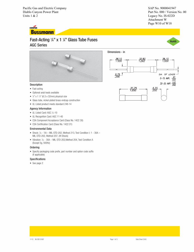
1113 BU-SB131067 Page 1 of 3 Data Sheet 2543
Fast-Acting 1/4” x 1 1⁄4” Glass Tube FusesAGC Series
Description• Fast-acting
• Optional axial leads available
• 1⁄4” x 1 1⁄4” (6.3 x 32mm) physical size
• Glass tube, nickel-plated brass endcap construction
• UL Listed product meets standard 248-14
Agency Information• UL Listed Card: AGC 1⁄20-10
• UL Recognition Card: AGC 11-40
• CSA Component Acceptance Card (Class No. 1422 30)
• CSA Certification Card (Class No. 1422 01)
Environmental Data• Shock: 1⁄20 - 3⁄4A – MIL-STD-202, Method 213, Test Condition I; 1 - 30A –
MIL-STD-202, Method 207, (HI Shock)
• Vibration: 1⁄20 - 30A – MIL-STD-202,Method 204, Test Condition A (Except 5g, 500Hz)
Ordering• Specify packaging code prefix, part number and option code suffix
(if applicable)
Specifications• See page 2
Dimensions - in
Pacific Gas and Electric Company Diablo Canyon Power Plant Units 1 & 2
SAP No. 9000041947 Part No. 000 / Version No. 00 Legacy No. IS-022D Attachment W Page W10 of W18

All dimensions are in inches. Tolerances (except noted): .xx = ±.02” (,51 mm), .xxx = ± .005” (,127 mm).All specifications are to the latest revisions. Specifications are subject to change without notice.Registered trademarks are the property of their respective companies.
Model 2269Insulated Double Banana Jack
Sales: 800-490-2361 Fax: 888-403-3360 Technical Support: 800-241-2060 ([email protected])For “Where to Buy” information, visit the Pomona web site at www.pomonaelectronics.com
Rev: 100D1093887
Page 1 of 1
FEATURES:Mounts in panels from .070” to .375” (1.60mm to 9.53mm).
MATERIALS:Banana Jack: Bright Tin Plated BrassMounting Base: PolycarbonateInsulator: PolycarbonateLockwasher: Nickel Plated SteelHex Nut: 3/8” ¼-32 Nickel Plated BrassSolder Turret: Bright Tin Plated Brass
RATINGS:Operating Voltage: Hands free usage in controlled voltage environments: 2500 Vrms maximum. For CE compliance: not
intended for hand-held use at voltages above 33 Vrms/70 Vdc.Operating Temperature: +239ºF (+115ºC) Max.Current: 15 Amperes ORDERING INFORMATION:
Model 2269-0 (Black Base)Model 2269-2 (Red Base)
Pacific Gas and Electric Company Diablo Canyon Power Plant Units 1 & 2
SAP No. 9000041947 Part No. 000 / Version No. 00 Legacy No. IS-022D Attachment W Page W11 of W18

RE
FER
EN
CE
- TR
ICO
NE
X B
AFF
LE H
EA
T D
EFL
EC
TOR
(em
ail a
nd d
wg)
Pag
e 3
of 3
Pacific Gas and Electric Company Diablo Canyon Power Plant Units 1 & 2
SAP No. 9000041947 Part No. 000 / Version No. 00 Legacy No. IS-022D Attachment W Page W12 of W18

General Purpose RelaysIndustrial Relays
KUP Series Panel Plug-in Relay
08-2011, Rev. 0811www.te.com© 2011 Tyco Electronics Corporation,a TE Connectivity Ltd. company
Datasheets and product specification according to IEC 61810-1 and to be used only together with the ‘Definitions’ section.
Datasheets and product data is subject to the terms of the disclaimer and all chapters of the ‘Definitions’ section, available at http://relays.te.com/definitions
Datasheets, product data, ‘Definitions’ sec-tion, application notes and all specifications are subject to change.
1
Potter & Brumfield
AgCdO, 4 pole (continued) 1/3HP, 120VAC 1/2HP, 250VAC Total load not to exceed 30 A, 28 VDC, 120 VAC and 20 A, 250 VAC AgSnOInO 10A, 277VAC, pf = 0.8 100x103 Mechanical endurance 10x106 ops.
Coil Data Coil voltage range 5 to 110VDC 6 to 240VACCoil insulation system according UL Class BCoil versions, DC coil Coil Rated Operate Coil Rated coil code voltage voltage resistance power VDC VDC Ω±10% W 1, 2 and 3 pole 5 5 3.75 21 1.2 6 6 4.5 32.1 1.125 12 12 9.0 120 1.2 24 24 18.0 472 1.25 48 48 36.0 1800 1.3 110 110 82.5 10000 1.25 4 pole 5 5 3.75 14 1.8 6 6 4.5 20 1.8 12 12 9.0 80 1.8 24 24 18.0 320 1.8 48 48 36.0 1250 1.85 110 110 82.5 6720 1.8All figures are given for coil without preenergization, at ambient temperature +23°C.
Coil versions, AC coil Coil Rated Operate Coil Rated coil code voltage voltage resistance power VAC VAC Ω±15% VA 1 and 2 pole 6 6 5.1 6 2.0 12 12 10.2 24 2.0 24 24 20.4 85 2.0 120 120 102.0 2250 2.1 240 240 204.0 9110 2.1 3 and 4 pole 6 6 5.1 4.2 2.8 12 12 10.2 18 2.8 24 24 20.4 72 2.8 120 120 102.0 1700 2.9 240 240 204.0 7200 2.9
All figures are given for coil without preenergization, at ambient temperature +23°C.
� AC coils: 5-240VAC, 50/60 Hz.; DC coils 6-110VDC� Contact arrangements of 1 form X, 1-3 form A and 1-4 form C� Wide selection of termination and mounting styles� PC terminals available� Push-to-test button and indicator lamp options� Sockets available for panel, DIN rail or PCB mounting� Class B coil insulation
Typical applications Vending, commercial sewing, tool/die equipment, robotics, timers, welding, HVAC, medical, power generators
Approvals UL E22575; CSA LR15734Technical data of approved types on request
Contact DataContact arrangement 1 Form X (NO-DM); 1-3 Form A (NO); 1-4 Form C (CO)Rated voltage 240VAC Rated current 10AContact material Ag AgCdO AgSnOInOMin. recommended contact load 100mA, 12VDC 300mA, 12VDC 300mA, 12VDCFrequency of operation 360 ops./hr 360 ops./hr 360 ops./hrOperate/releases time max. 15/10ms Bounce time max. 17ms
Contact ratingsType Load CyclesUL 508 Ag, 1, 2 and 3 pole 5A, 240VAC 5A, 28VDC 1/6HP, 120VAC 2.5A, 120VAC, tungsten 1/3HP, 240VAC 0.5A, 120VDC 5FLA, 15LRA, 250VACAg, 4 pole 5A, 240VAC 2.5A, 120VAC, tungsten 0.5A, 120VDC 1/6HP, 120VAC 1/3HP, 240VACAgCdO, 1, 2 and 3 pole 10A, 240VAC 10A, 32VDC 5FLA, 15LRA, 250VAC 1/3HP, 120VAC 5A, 120VAC, tungsten 1/2HP, 250VAC 0.5A, 125VDC 10FLA, 40LRA, 125VAC 3A, 600VAC 1/2HP, 480VAC 1/2HP, 600VAC 1HP, 480 VAC, 3 phase AgCdO, 4 pole 10A, 240VAC 5A, 120VAC, tungsten 0.5A, 120VDC 10A, 28VDC, resistive 10FLA, 30LRA, 125VAC 5FLA, 15LRA, 250 VAC 30x103
125VA, 250 VAC
Pacific Gas and Electric Company Diablo Canyon Power Plant Units 1 & 2
SAP No. 9000041947 Part No. 000 / Version No. 00 Legacy No. IS-022D Attachment W Page W13 of W18

General Purpose RelaysIndustrial Relays
KUP Series Panel Plug-in Relay (Continued)
08-2011, Rev. 0811www.te.com© 2011 Tyco Electronics Corporation,a TE Connectivity Ltd. company
Datasheets and product specification according to IEC 61810-1 and to be used only together with the ‘Definitions’ section.
Datasheets and product data is subject to the terms of the disclaimer and all chapters of the ‘Definitions’ section, available at http://relays.te.com/definitions
Datasheets, product data, ‘Definitions’ sec-tion, application notes and all specifications are subject to change.
2
Potter & Brumfield
Other Data (continued) Category of environmental protection IEC 61810 RT0 - open relay; RTI - dust protectedTerminal type Quick connects (QC), .187, .205 or .250; PCB-THT Terminal retention, push force QC .205 17 lbs for 3s QC .187, QC .250, PCB 25 lbs for 3s Weight 85gPackaging/unit tray/25 pcs., box/150pcs.
Accessories For details see datasheet Sockets and Accessories, KUP Relays Product Code Description27E893 DIN socket (use 20C318 clip)27E121 Track mount socket (use 20C314 clips)27E043 Chassis mount/solder eyelet socket (use 20C254 clip)27E046 Chassis mount/PCB socket (use 20C254 clip)27E067 Chassis mount/quick connect socket (use 20C254 clip)27E396 Snap-in/quick connect socket (use 20C254 clip)
Insulation Data Initial dielectric strength between open contacts 1200Vrms
between contact and coil 2200Vrms
between adjacent contacts 2200Vrms
Initial insulation resistance between insulated elements 100MΩ, 500VDC
Other Data Material compliance: EU RoHS/ELV, China RoHS, REACH, Halogen content refer to the Product Compliance Support Center at www.te.com/customersupport/rohssupportcenterAmbient temperature DC coil Enclosed relays, 4 pole: -45ºC to 50ºC Enclosed relays, 1-3 pole: -45ºC to 70ºC Open relays: 15ºC higher maximum AC coil Enclosed relays, 3 and 4 pole: -45°C to +45°C Enclosed relays, 1 and 2 pole: -45ºC to +55ºC Open relays: 15°C higher maximum Maximum allowable ambient temperature vs voltage (KUP enlcosed)
Dimensions
KU bracket type
2.43 MAX.*(61.72)
2.33 MAX.**(59.18)
2.29 MAX.***(58.17)
1.437(36.50).19
(4.8)
.63(16.0)
(2) #6-32 THREADTAPPED HOLES
2.27 MAX.*(57.7)
2.171 MAX.**(55.14)
2.125 MAX.***(53.98)
.16(4.1)
.63(16.0)
X X
X
KU stud type
2.27 MAX.*(57.7)
2.171 MAX.**(55.14)
2.125 MAX.***(53.98) 1.391
(35.33)
.065(1.65)
1.39 MAX.*(35.3)
1.29 MAX.**(32.8)
1.25 MAX.***(31.8)
.437(11.10)
.218(5.54)
1.282 MAX.(35.56)
1.468 MAX.(37.29)
1 2 34 5 6
7 8 9
A B
.150TAB WIDTH
(3.81)
.31(7.9)
.109 MAX.(2.77)
#6-32 THREAD
1.687 MAX.(42.85)
.031 REF.(.79)
.031 REF.(.79)
Seated Heights For KU (open) Relays
1.391” (35.33mm) for #6-32 studwith .218” (5.54mm) locating tab.
1.52” (38.6mm) for bracketwith 2-#6 32 tapped holes.
1.282” (32.56mm) for #6-32 tapped corewith .125” (3.18mm) or .218” (5.54mm) locating tab.
2.046” (51.97mm) for relaywith printed circuit terminals.
STUD TYPE also available with .125” (3.18mm)tab, as well as without stud and locating tab.Models without stud have core tapped #6-32THREAD, .25” (6.4mm) minimum depth.
*Dimensions with .250” (6.35mm) terminals. ** Dimensions with .110” (2.79mm) or .205” (5.21mm) terminals.*** Dimensions with .187” (4.75mm) terminals.
Relay front diagrams
1.406 MAX.(35.71)
1.531 MAX.(38.89)
1 2 34 5 6
7 8 9
A B
1 2 34 5 6
7 9
A B
1.406 MAX. (35.71)
1.531 MAX.(38.89)
Models with 6.35mm 1-3 pole models with 4 pole models (.250) QC terminals all other terminals
1 2 3 4
A B
5 6 7 8
9 10 11 121.406 MAX.
(35.71)
1.531 MAX.(38.89)
1 2 3 4
70°
60°
50°
40°
30°
20°100 110 120 130 140 150 160
% of Nominal Voltage DC
Max
. A
mbi
ent
Tem
p. °
C
1.8 Watt DC Coi l
1.2 Watt DC Coil
75°70°
60°
50°
40°
30°
20°100 110 120 130 140% Of Nominal 60 Hz. Voltage
2.7 VA 60 Hz. COIL
2.0 VA 60 Hz. CO
IL
Max
. A
mbi
ent
Tem
p. °
C
75°
Pacific Gas and Electric Company Diablo Canyon Power Plant Units 1 & 2
SAP No. 9000041947 Part No. 000 / Version No. 00 Legacy No. IS-022D Attachment W Page W14 of W18

General Purpose RelaysIndustrial Relays
KUP Series Panel Plug-in Relay (Continued)
08-2011, Rev. 0811www.te.com© 2011 Tyco Electronics Corporation,a TE Connectivity Ltd. company
Datasheets and product specification according to IEC 61810-1 and to be used only together with the ‘Definitions’ section.
Datasheets and product data is subject to the terms of the disclaimer and all chapters of the ‘Definitions’ section, available at http://relays.te.com/definitions
Datasheets, product data, ‘Definitions’ sec-tion, application notes and all specifications are subject to change.
3
Potter & Brumfield
Terminal dimensions
4.75mm (.187) quick connect 5.21mm (.205) quick connect 1.19mm (.047) printed circuit 6.35mm (.250) quick connect
.205± .002(5.21± .05)
.156(3.96)
.093(2.36)
.285(7.24)
.316 REF.(8.03)
.032(.81)THICKNESS
HEADER
.035(.89)
.156(3.96)
.032(.81)
THICKNESS
.093(2.36)
HEADER
.237(6.02)
.268 REF.(6.81)
.047(1.19)
.180(4.57)
.156(3.96)
X Is For Terminal Dimensions.See Teminal Drawings.
KUP top flange case
KUP core / stud mount case
.125(3.18)
.078(1.98)
.187±.002(4.75±.05)
.250(6.35)
281 REF.(7.14)
THICKNESS .020(.51)
HEADER
.125 DIA.(3.18)
.035(.89)
.250 ± .003(6.35 ± .08)
HEADER
.305(7.75)
.312(7.92)
.106(2.69)
.358 REF.(9.09)
THICKNESS.032(0.81)
KUP plain case
XX
X
X
.187 (4.75) DIA.PUSH-TO-TEST BUTTONAVAILABLE
.288(7.32)
1.968 MAX.†(49.99)
1.906 MAX.‡(48.41)
.219 MAX.(5.56)
1.531 MAX.(38.89)
1 2 34 5 6
7 8 9
A B
1.406 MAX.(35.71)
1.39 MAX.*(35.3)
1.29 MAX.**(32.8)
1.25 MAX.***(31.8)
1.968 MAX.†(49.99)
1.906 MAX.‡(48.41)
X
1.43 MAX.(36.27)
.437 .010(11.10 .25)
.130(3.30)
1.74 MAX.(44.2)
.312(7.92)
STUD with#6-32 THREADor CORE TAPPED#6-32
.085 MAX.(2.16)
#6-32 THREAD
1.968 MAX. †(49.99)
1.906 MAX. ‡(48.41)
.38(9.7)
.16(4.1)
1 2 34 5 6
7 8 9
A B
1.518 MAX.(38.56)
1.373 ± .010(34.87 ± .25)
1.713 ± .003(43.51 ± .08)
1.989 ± .003(50.52)
.178 TYP.(4.52)
2.248 MAX.(57.10)
.078 TYP.(1.98)
KUP bracket mount case
1.968 MAX.†(49.99)
1.906 MAX.‡(48.41)
.75(19.1)
2.90 MAX.(73.7)
.078 R. TYP.(1.98)X
1.531 MAX.(38.89)
.312TYP.(7.92)
.375(9.53) .437
(11.10)
X
2.500(63.50)
X
.625 TYP.(15.88)
.06(1.52)1.
128
(28.
65)
1 .40
6 MA
X.
(35.
71)
PUSH-TO-TEST BUTTONAVAILABLE
.07(1.8)
KUP stud on end case
† Dimensions with .250” (6.35mm) terminals.‡ Dimensions with .187” (4.75mm and .205” 5.21mm) terminals.
*Dimensions with .250” (6.35mm) terminals. ** Dimensions with .110” (2.79mm) or .205”(5.21mm) terminals.*** Dimensions with .187” (4.75mm) terminals.
Terminal assignment
1 Form X 1 Form C 2 Form C 3 Form C 4 Form C 1 Form A (delete 2) 2 Form A (delete 1 & 3) 3 Form A (delete 1, 2 & 3)
4 6
A B A B
7
5
2
7
4
A B
1
9
6
3
A B
7
4
1
9
6
3
8
5
2
A B
9
1
5
10
2
6
11
7
3 4
8
12
Dimensions (continued)
Pacific Gas and Electric Company Diablo Canyon Power Plant Units 1 & 2
SAP No. 9000041947 Part No. 000 / Version No. 00 Legacy No. IS-022D Attachment W Page W15 of W18

General Purpose RelaysIndustrial Relays
KUP Series Panel Plug-in Relay (Continued)
08-2011, Rev. 0811www.te.com© 2011 Tyco Electronics Corporation,a TE Connectivity Ltd. company
Datasheets and product specification according to IEC 61810-1 and to be used only together with the ‘Definitions’ section.
Datasheets and product data is subject to the terms of the disclaimer and all chapters of the ‘Definitions’ section, available at http://relays.te.com/definitions
Datasheets, product data, ‘Definitions’ sec-tion, application notes and all specifications are subject to change.
4
Potter & Brumfield
Product code structure Typical product code KUP -14 A 1 5 -120
Type KU Open style relay KUP Enclosed relay
Contact arrangement 1 1 form A (1 NO) 3 1 form X (1 NO-DM) 5 1 form C (1 CO) 7 2 form A (2 NO) 11 2 form C (2 CO) 12 3 form A (3 NO) 14 3 form C (3 CO) 17 4 form C (4 CO)
Coil Input A AC, 50/60Hz D DC
Mounting and options KU 1 #6-32 mounting stud, 5.54mm (.218in) locating tab 3 #6-32 tapped core, 3.18mm (.125in) locating tab 4 #6-32 tapped core, 5.54mm (.218in) locating tab 5 #6-32 tapped core, no locating tab KUP 1 Socket mount (plain) case 2 Socket mount (plain) case with push-to-test button 1) 3 Socket mount (plain) case with indicator lamp 2) 4 Socket mount (plain) case with indicator lamp and push-to-test button 1) 2) 5 Bracket mount case A Plain case with #6-32 stud and locating tab E Plain case with #6-32 tapped core and locating tab T Top flange case 1) 1) Not available with four pole models (Contact arrangement 17). 2) Indicator lamps are available on models with the following coils: 6-24VAC and VDC, 110VDC and 120-240VAC. Only models with 120-240VAC coils are UL recognized.
Terminal and contact material
1 and 2 pole models 1 4.75mm (.187in) quick connect/solder; Ag, 5A 3 1.19mm (.047in) PCB; Ag, 5A 5 4.75mm (.187in) quick connect/solder; AgCdO, 10A 7 1.19mm (.047in) PCB; AgCdO, 10A J 6.35mm (.250in) quick connect/solder; Ag, 5A K 6.35mm (.250in) quick connect/solder; AgCdO, 10A P 4.75mm (.187in) quick connect/solder; AgSnOInO, 10A S 1.19mm (.047in) PCB, AgSnOInO; 10A W 6.35mm (.250in) quick connect/solder; AgSnOInO, 10A
3 pole models 1 4.75mm (.187in) quick connect/solder; Ag, 5A 3 1.19mm (.047in) PCB; Ag, 5A 5 4.75mm (.187in) quick connect/solder; AgCdO, 10A 7 1.19mm (.047in) PCB; AgCdO, 10A P 4.75mm (.187in) quick connect/solder; AgSnOInO, 10A S 1.19mm (.047in) PCB, AgSnOInO; 10A
4 pole models 1 4.75mm (.187in) quick connect/solder; Ag, 5A 3) 3 1.19mm (.047in) PCB; Ag, 5A 4 2.79mm (.110in) quick connect/solder; Ag, 5A 5 4.75mm (.187in) quick connect/solder; AgCdO, 10A 3) 7 1.19mm (.047in) PCB; AgCdO, 10A 9 2.79mm (.110in) quick connect/solder; AgCdO, 10A P 4.75mm (.187in) quick connect/solder; AgSnOInO, 10A 3) S 1.19mm (.047in) PCB, AgSnOInO; 10A U 2.79mm (.110in) quick connect/solder; AgSnOInO, 10A 2) 3) 4 pole KUP with 4.75mm (.187in) terminals will not plug into sockets. Must use 2.79mm (.110) terminals for socket mounting.
Au flashed contact option
Leave Blank No Au flashing on contacts F Optional Au flashing on contacts
Coil voltage Coil code: please refer to coil versions table
PCB layoutBottom view on solder pins
1 form X version 3 pole version 4 pole version (Omit unnecessry holes for form A and 2 pole types)
.875(22.23)
.626(15.90)
.076 DIA. TYP.(1.93)
.626(15.90)
.328(8.33)
.437(11.10)
.875(22.23)
.076 DIA. TYP.(1.93)
.206(5.23)
.328(8.33)
.510(12.95)
.170(4.32)
.076 DIA. TYP.(1.93)
.626(15.90)
.340(8.64)
1.020(25.91)
.206(5.23)
Pacific Gas and Electric Company Diablo Canyon Power Plant Units 1 & 2
SAP No. 9000041947 Part No. 000 / Version No. 00 Legacy No. IS-022D Attachment W Page W16 of W18
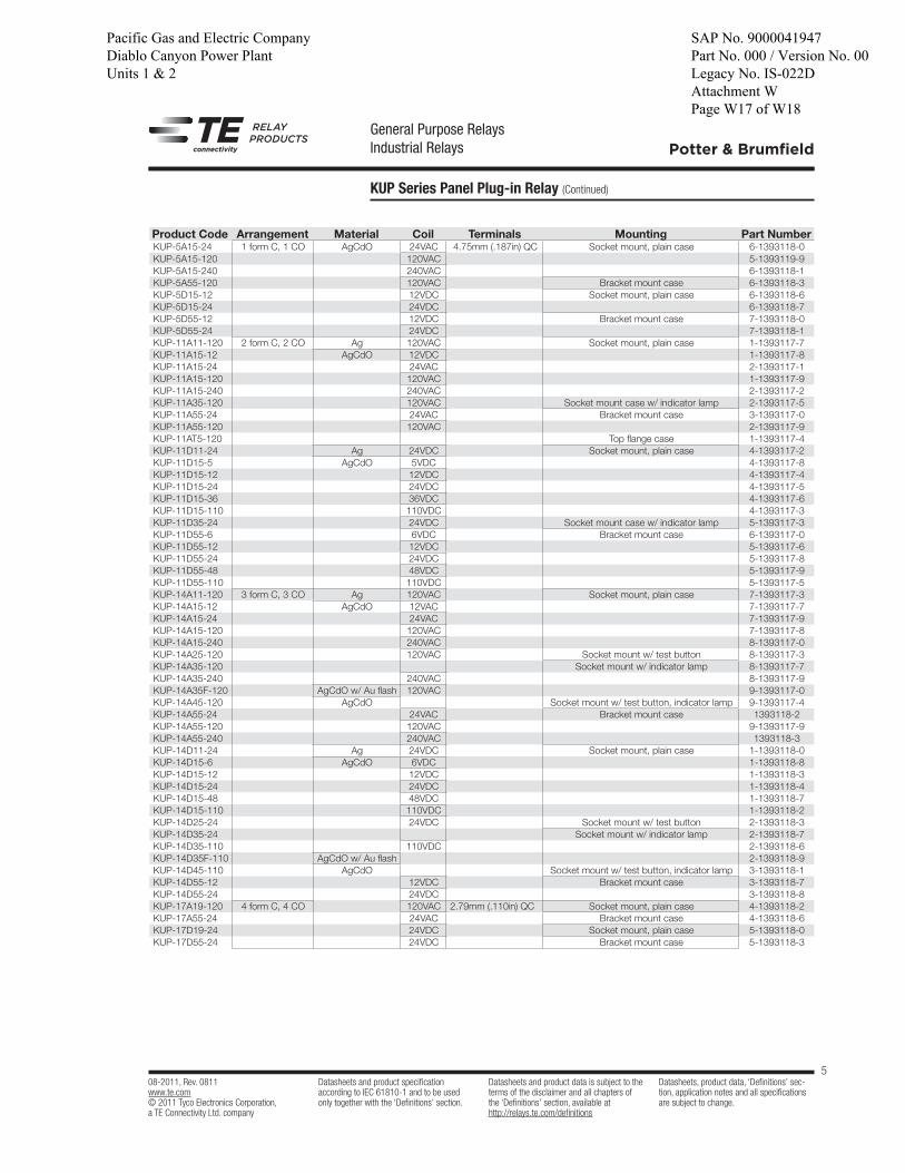
General Purpose RelaysIndustrial Relays
KUP Series Panel Plug-in Relay (Continued)
08-2011, Rev. 0811www.te.com© 2011 Tyco Electronics Corporation,a TE Connectivity Ltd. company
Datasheets and product specification according to IEC 61810-1 and to be used only together with the ‘Definitions’ section.
Datasheets and product data is subject to the terms of the disclaimer and all chapters of the ‘Definitions’ section, available at http://relays.te.com/definitions
Datasheets, product data, ‘Definitions’ sec-tion, application notes and all specifications are subject to change.
5
Potter & Brumfield
Product Code Arrangement Material Coil Terminals Mounting Part NumberKUP-5A15-24 1 form C, 1 CO AgCdO 24VAC 4.75mm (.187in) QC Socket mount, plain case 6-1393118-0
KUP-5A15-120 120VAC 5-1393119-9
KUP-5A15-240 240VAC 6-1393118-1
KUP-5A55-120 120VAC Bracket mount case 6-1393118-3
KUP-5D15-12 12VDC Socket mount, plain case 6-1393118-6
KUP-5D15-24 24VDC 6-1393118-7
KUP-5D55-12 12VDC Bracket mount case 7-1393118-0
KUP-5D55-24 24VDC 7-1393118-1
KUP-11A11-120 2 form C, 2 CO Ag 120VAC Socket mount, plain case 1-1393117-7
KUP-11A15-12 AgCdO 12VDC 1-1393117-8
KUP-11A15-24 24VAC 2-1393117-1
KUP-11A15-120 120VAC 1-1393117-9
KUP-11A15-240 240VAC 2-1393117-2
KUP-11A35-120 120VAC Socket mount case w/ indicator lamp 2-1393117-5
KUP-11A55-24 24VAC Bracket mount case 3-1393117-0
KUP-11A55-120 120VAC 2-1393117-9
KUP-11AT5-120 Top flange case 1-1393117-4
KUP-11D11-24 Ag 24VDC Socket mount, plain case 4-1393117-2
KUP-11D15-5 AgCdO 5VDC 4-1393117-8
KUP-11D15-12 12VDC 4-1393117-4
KUP-11D15-24 24VDC 4-1393117-5
KUP-11D15-36 36VDC 4-1393117-6
KUP-11D15-110 110VDC 4-1393117-3
KUP-11D35-24 24VDC Socket mount case w/ indicator lamp 5-1393117-3
KUP-11D55-6 6VDC Bracket mount case 6-1393117-0
KUP-11D55-12 12VDC 5-1393117-6
KUP-11D55-24 24VDC 5-1393117-8
KUP-11D55-48 48VDC 5-1393117-9
KUP-11D55-110 110VDC 5-1393117-5
KUP-14A11-120 3 form C, 3 CO Ag 120VAC Socket mount, plain case 7-1393117-3
KUP-14A15-12 AgCdO 12VAC 7-1393117-7
KUP-14A15-24 24VAC 7-1393117-9
KUP-14A15-120 120VAC 7-1393117-8
KUP-14A15-240 240VAC 8-1393117-0
KUP-14A25-120 120VAC Socket mount w/ test button 8-1393117-3
KUP-14A35-120 Socket mount w/ indicator lamp 8-1393117-7
KUP-14A35-240 240VAC 8-1393117-9
KUP-14A35F-120 AgCdO w/ Au flash 120VAC 9-1393117-0
KUP-14A45-120 AgCdO Socket mount w/ test button, indicator lamp 9-1393117-4
KUP-14A55-24 24VAC Bracket mount case 1393118-2
KUP-14A55-120 120VAC 9-1393117-9
KUP-14A55-240 240VAC 1393118-3
KUP-14D11-24 Ag 24VDC Socket mount, plain case 1-1393118-0
KUP-14D15-6 AgCdO 6VDC 1-1393118-8
KUP-14D15-12 12VDC 1-1393118-3
KUP-14D15-24 24VDC 1-1393118-4
KUP-14D15-48 48VDC 1-1393118-7
KUP-14D15-110 110VDC 1-1393118-2
KUP-14D25-24 24VDC Socket mount w/ test button 2-1393118-3
KUP-14D35-24 Socket mount w/ indicator lamp 2-1393118-7
KUP-14D35-110 110VDC 2-1393118-6
KUP-14D35F-110 AgCdO w/ Au flash 2-1393118-9
KUP-14D45-110 AgCdO Socket mount w/ test button, indicator lamp 3-1393118-1
KUP-14D55-12 12VDC Bracket mount case 3-1393118-7
KUP-14D55-24 24VDC 3-1393118-8
KUP-17A19-120 4 form C, 4 CO 120VAC 2.79mm (.110in) QC Socket mount, plain case 4-1393118-2
KUP-17A55-24 24VAC Bracket mount case 4-1393118-6
KUP-17D19-24 24VDC Socket mount, plain case 5-1393118-0
KUP-17D55-24 24VDC Bracket mount case 5-1393118-3
Pacific Gas and Electric Company Diablo Canyon Power Plant Units 1 & 2
SAP No. 9000041947 Part No. 000 / Version No. 00 Legacy No. IS-022D Attachment W Page W17 of W18

Fw: ALS rack arrangementISMAIL T KISISEL to: STEVEN S KWON 07/13/2016 05:44 PM
----- Forwarded by ISMAIL T KISISEL/Sargentlundy on 07/13/2016 05:44 PM -----
From: "TURINSKY, ADAM" To: "'ISMAIL.T.KISISELDate: 07/13/2016 05:00 PMSubject: FW: ALS rack arrangement
Ismail,�See�the�email�below�regarding�the�Potter�&�Brumfield�KUP�14D15�48�relay�in�the�ALS�racks.��Reference�drawings�926240�1,�926240�6,�926240�12�and�926240�15.�The�relay�is�referred�to�by�the�Component�ID�(K1W)�for�this�model�relay�shown�on�drawing�926240�1�(ALS�Set�I,�BOM�Item�47).��For�ALS�Set�II,�Set�III�and�Set�IV�the�Component�ID’s�are�K2W,�K3W�and�K4W,�respectively.��Adam�From: Reinholdt, John Sent: Wednesday, July 13, 2016 10:31 AMTo: TURINSKY, ADAMCc: McRitchie, Travis WSubject: RE: ALS rack arrangement�Adam:�The�K1W�relay�appears�on�electrical�schematic�926240�146�Sheet�5�of�5.�This�relay�is�used�as�an�interface�between�the�channel�bypass�switches�and�the�Main�Annunciator�System�(MAS).��This�circuit�will�generate�an�alarm�in�the�Control�Room�when�a�bypass�switch�is�placed�in�the�bypass�position.��The�relay�is�designated�as�“Q”�since�it�does�provide�electrical�isolation�between�the�1E�power�source�for�the�bypass�switch�contacts,�and�the�non�1E�MAS�power.��If�there�were�contact�chatter�on�the�K1W�relay�during�a�seismic�event,�it�may�generate�a�spurious�alarm,�but�it�would�not�adversely�impact�any�Reactor�Trip�for�ESFAS�actuation.�John�From: TURINSKY, ADAMSent: Wednesday, July 13, 2016 10:13 AMTo: Reinholdt, JohnSubject: ALS rack arrangement�BOM�item�47.�Adam�TurinskyIntegrated�Services�Supplier�(ISS)I&C�Engineering���Diablo�Canyon�Power�Plant
Pacific Gas and Electric Company Diablo Canyon Power Plant Units 1 & 2
SAP No. 9000041947 Part No. 000 / Version No. 00 Legacy No. IS-022D Attachment W Page W18 of W18