dcre_whitepaper
TRANSCRIPT

1
Digital Cinema Reality Engine
Trident Digital Media, Inc.
Preliminary Version 1.0 Dated:2003-11-26
DPTV™ Product Family

2
1. Introduction DCReTM, digital cinema reality engine, is Trident’s proprietary technology to address the need for today’s high-end multimedia digital television application requirement. It embodies Trident’s DPTV™ design vision in offering highly integrated and common-chassis multimedia digital television design platform that is both a high quality television set as well as a multimedia display terminal for PC graphics. This design platform, as depicted as Figure 1, is able to receive and decode the conventional NTSC/PAL/SECAM broadcasting signals, to display PC VGA inputs and to receive high definition component inputs from the digital set-top box.
Multifunctional
HDTVMonitorDesign
Platform
PC VGA
HDTV/DVBSTB
Digital RGB
ConventionalNTSC/PAL/SECAM
Figure 1: DPTV™ is the multi-functional HDTV monitor design platform
Progressive television has come a long way since the days of cathode ray tubes. The new generation of display devices include the latest liquid crystal display (LCD) TV, plasma display panel (PDP) TV, micro display projectors and DLP frontal and rear projection television. All these new and exciting display technologies have created a requirement for the television manufacturers to establish a video processor that can process different video source correctly and display the ultimate video quality. DCRe™ technology converts analog video signal into high-fidelity digital signal for both both motion and still pictures. Unlike conventional high-end LCD TV designs, DCRe™ combines various stages of video processing into one single chip. As illustrated in Figure 2, DCRe™ combines a 3D digital comb video decoder, an intelligent de-interlacer, a scaler, and LCD overdrive circuits all into one chip. While utilizing Trident’s patented unified memory architecture (UMA), all these functions share one single frame buffer to perform 3D digital-comb video decoding, interlace to progressive de-interlacing, image scaling, and overdriving to enhance the LCD panel response time.

3
SDRAM
3D Digital CombDecoder
CompositeVideo De-
interlacer(DRC)
SDR
AM
SDR
AM
SCALER
SDR
AM
SDR
AM SDRAM
LCDOverdrive
To LCDPanel
Conventional LCD TVElectronics Design
DCReTMComposite
Video To LCDPanel
SDRAM
SDRAM
UM
A
PanelTV LCD TVElectronics Design
Figure 2: DCReTM technology simplifies the LCD TV design and manufacturability

4
Figure 3: DRCeTM Functional Block as Implemented Inside DPTVTMSVP
Figure 3 illustrates the internal system block diagram of the DCReTM technology. The composite video broadcasting signal (CVBS) is first entered into the TCD3 3D video decoder, then data is sent to the capture port to be captured into the frame buffer. The DCRe memory arbitor is the key in the UMA architecture that acts as the traffic cop controlling the video data traffic from the TCD decoder, de-interlacer, and scaler. The processed data is then sent to the main picture display block to be displayed out in the later stage. In addition to the total integration of a 3D-comb video decoder, de-interlacer, scaler and LCD overdrive functions, the DCRe™ technology includes many image enhancement techniques using the embedded digital video processing technique. These digital imaging processing technique includes 3:2 pull down, edge enhancement, skin-tone correction, panorama mode, multi picture mode (POP and PIP), digital enhanced translucent image (DETI, average picture level read-back, (APL) and embedded high-precision 10-bit video DAC to output to digital CRT television. Furthermore, DCReTM technology 10-bit end-to-end video processing provides the best video image fidelity to vividly re-create the original video images on the display screen. This end-to-end processing starts with the high-precision 10-bit ADC inside the TDC3 decoder, all intermediate video processing data path to the end high image quality 10-bit video DAC. Working in tandem, the 10-bit path offers the user a non-compromised video image. As
FrameBuffer
Controller
Frame RateConverter
CVBS1Main Picture
Display3:2 Pull down
Panorama & Non-Linear Scalers
14 D
PIP / SVGADisplay
Scalers
VBI / OSDDisplay
Main Picture,PIP, & SVGACapture Ports
with Filters
CPU & OSDInterface
GammaLUTAuto Color
Adjustment
CSC
Blender
Chroma Key
VM Control
H & VVoltage
Protection
10-BitDAC
CRTC / DPLL(Digital Auto
Lock)
Clock PLL
Component
S-Video
PIP(YUV422)
SVGA(RBG 16/24)
8-BitParallel Bus
I 2C
Crystal
H syncV sync
RGB
VM
H & VProtection
Frame Buffer
TCD33D
CombVideo
Decoder
Video Capture Port1 (MP)
Video CapturePort 2 (PIP)
CCIR 601CCIR 656HD YPrPb
24-bitRGBout

5
compared to the discrete conventional LCD TV designs, the data is degraded from the current stage to the next stage, resulting in video image degradation. Figure 4 depicts the effects of the DCRe™ video fidelity and its comparison to the images where there is picture degradation.
a. DCReTM 10-bit end-to-end processing. Thepicture quality is crisp, and there is no colorbanding artifact.
b. Conventional LCD TV video image qualitydue to imprecise digital video processing.This results in color banding and noiseartifacts.
Figure 4: DCReTM displays video fidelity In the following sections of this paper, the specific features of DCReTM technology will be explained in more details. The features include a 3D-comb video decoder, motion adaptive de-interlacing, 3:2 pull-down DVD mode, video format conversion-scaler, horizontal/vertical sharpness, digital noise reduction, average picture level (APL) feedback, and LCD overdrive. This paper is an attempt to help the OEMs and the consumer understand the important features in DCReTM for an HDTV-ready TV set so that they can make an educated decision when they want to start the LCD TV design as well as when to purchase their next TV. Lastly, since TCD3 is an advanced 3D-comb digital decoder. It contains the necessary vertical blanking interval (VBI) that supports CC and teletext decoding, teletext, WSS detection for 480i signal and ID1 detection for 480P

6
2. 3D Digital Comb Video Decoder–Motion Adaptive Comb filter technique
The integrated TCD3 NTSC/PAL/SECAM 3D comb video decoder can take an analog TV signal and convert it to a digital format. The analog TV signal can be in the composite, S-Video, or component format. The two internal analog switches can be programmed to select different input signal formats. The selected analog TV signal is sent to the Automatic Gain Control (AGC) and then to a 10-bit ADC. The input sampled by the ADC’s can be in NTSC (and variations), PAL (and variations), SECAM, and all progressive modes. The input signal can have Macrovision, which the decoder will detect and compensate for. It also supports the WSS input detection. The non-decoded signal goes to a programmable 3D comb filter to maintain the vertical chrominance resolution during the luminance (Y) and chrominance (C) separation. Even though most new advanced TVs are equipped with S-video and component inputs, majority households still use composite input as their major video source. Today most cable feeds use one cable line that contains decoded baseband video chroma, luma, and audio in the same line for transmission purpose. Therefore, a TV’s composite video reception quality is mainly dependent on the separation or the retrieval of the chroma and luma from the baseband video. The 2D Digital comb filter resolves some cross color issues. It cannot remove all cross colors as show in Figure 5.a. The 3D digital comb filter can perfectly separate the chroma and the luma content from the same base band for stationary video. 3D adaptive comb filter improves the luma-chroma separation process such that the luma and chroma are perfectly separated for stationary images. Figure 5 shows a picture from a 2D comb filter and another picture from a 3D motion adaptive comb filter for comparison.

7
a. 2D Comb Filter Screen CaptureThe Y/C separation is not clean. Thispicture contains many false color.
b. 3D Motion Adaptive Comb Filter ScreenCapture3D comb filer provides a very crip and clear picture, nofalse color.
Figure 5. DCReTM Picture Comparion of 2D Comb Filter and 3D Motion Adaptive Comb Filter
c. 2D Comb Filter Live Video ScreenCapture
d. 3D Comb Filter Screen CaptureThe picture is clear and crisp. Allfalse color artifacts are removed.r.
Figure 5: DCReTM Picture Comparison of 2D Comb Filter and 3D Motion Adaptive Comb Filter The fact that 3D digital comb filters are only found in high-end TV models explains the complexity and the expenditure involved in using a 3D digital comb filter. 3D digital comb filter implementation requires both memory and bandwidth. Furthermore, a 3D comb filter needs to correctly distinguish between moving and still pixels, which also presents a big challenge. Distinguishing between moving and still pixels is called Motion Detection. Trident’s TCD3 technology employs an advanced 0.25-micron process technology, adaptive motion detection, and UMA architecture to deliver an un-compromised video quality for mainstream TVs. The Theory of the 3D Adaptive Comb Filter Figure 6 shows a simplified block diagram of the 3D Adaptive Comb Filter. As shown in the figure the 3D Adaptive Comb Filter contains five functional blocks, namely 2D adaptive comb filter, temporal comb filter, motion detector, field-line memory, and filter bank.

8
(For Pixel with Motion)20 Adaptice Comb
YC Separator
(For Pixel withoutMotion)
Temporal CombYC Separator
MotionDetector
Field Buffers&
Line Buffers
Bandpass&
NotchFilterBanks
Mixer
Y_2D
C_2D
Y_T
C_T
K_Coef
Y_3D
C_3D
Figure 6: A block diagram of the 3D Adaptive Comb Filter
As shown in Figure 6, the 2D adaptive comb filter is an inter-field filter that is used when the pixel does not contain motion; while the temporal comb filter is an intra frame filter for pixels with motion. A temporal filter is used to separate the luma and chroma based on the pixels between the frames. If the picture is stationary, the pixels between frames (temporal direction) are identical except that the modulated chroma phase is 180 degrees out of phase accordingly. An example of the NTSC and PAL pixel planes is shown in Figures 7A and 7B.
Field n-2 Field n-1 Field n Field n+1 Field n+2
Y+C
Y-C
Y+C
mCVS525
Y-C
Y+C
mCVS263
mCVS262
Y-C
mCVS1
Y+C
pCVS0
Y-C
pCVS1
Y+C
pCVS262
Y-C
pCVS263
Y+C
Y-C
pCVS525
Y+C
Field n-2 Field n-1 Field n Field n+1 Field n+2
Y-C
Y+C
Y+C
mCVS625
Y+C
Y-C
mCVS313
Y-C
mCVS2
Y+C
mCVS1
Y+C
pCVS0
Y-C
Y-C
pCVS312
Y+C
Y-C
Y-C
Y-C
Y-C
Y-C
mCVS312
Y+C
Y-C
pCVS1
Y-C
pCVS2
Y+CY+C
Y+C
pCVS313
pCVS625
Y+C
Y+C
(A)
(B)
Figure 7A: NTSC pixels for 2 frames Figure 7B: PAL pixels for 2 frames
9
By adding and subtracting pixels between frames, the luma and the chroma can be perfectly separated from the composite signal. Most of the artifacts seen on the picture employing 2D adaptive YC separator are removed. However, there is a drawback in using the fixed temporal filter approach. If the area of the picture contains a movement, pixels between frames are no longer identical. Hence, a 2D adaptive YC comb filter will provide a better result. As a matter of fact, a motion detector is required to identify the area of the picture containing motion such that the good mix between the temporal comb filter and YC adaptive comb filter can be determined. Hence, the performance of the 3D adaptive comb filter strongly depends upon the quality of the motion-detector. The motion detector is a key component in the 3D Adaptive Comb Filter. It is based on the “Sum of Absolute Difference” algorithm. This unit uses a 3x5 neighborhood around the current pixel, pCVSO, from each image, and calculates the SAD (Sum of Absolute Differences) between them. The result of this SAD is used to determine the mixer value, k coefficient, using a lookup table. The lookup table is built into every picture using the noise threshold value, which is determined from the noise detector. Motion detection is used for each pixel in the picture. To provide a soft switching between the outputs from the 2D adaptive comb filter to the outputs from the temporal comb filter, a blending coefficient is derived based on the SAD value and the noise threshold value. If the noise threshold is unchanged, the larger SAD value of the large degree of motion is detected and more of the 2D comb filter outputs are used. Similarly, for small SAD values, a smaller degree of motion is detected and more of the temporal comb filter outputs are used.

10
3. Motion Adaptive De-Interlacing Composite Video Broadcast Signal (CVBS) is an interlaced signal used by both the NTSC and the PAL TV systems to save the Radio Frequency (RF) signal transmitting bandwidth. NTSC standards adopted in North America and some parts of Asia have 525 scan lines per video frame. The PAL standard adopted in Europe has 625 scan lines per video frame. An interlaced video frame is composed of even and odd fields, with each field containing half the number of scan lines. Therefore, interlaced video cannot provide a sufficient resolution for enhancing the picture quality. In order to increase resolution, more scan lines need to be added to increase the resolution to be near to that of HDTV. For example, a NTSC video with a 525I frame can be converted into a 525P frame. A 525P frame effectively doubles the display resolution and approach, similar to that of the HDTV video. The process by which an interlaced video source is converted into a progressive display is called De-Interlacing. There are essentially three ways of performing de-interlacing: scan line duplication, scan line interpolation, and motion adaptive de-interlacing. Motion adaptive de-interlacing is the most advanced and efficient algorithm for de-interlacing. The motion adaptive de-interlacing algorithm merges two to three consecutive fields to produce a video frame (See Figure 8). In Figure 8, to convert Interlaced display into Progressive display, additional scan lines are added between existing lines to make Field N into Frame N. This process needs to be performed on each consecutive field to convert them into individual frames.
525-LineOdd Field N
525-Line Even Field N-1
525-Line EvenField N+1
2223242526
44454647
X2223242526
Scan Line
Pixela1 a2 a3
b1 b2 b3
c1 c2 c3
d1 d2 d3
Figure 8: Motion Adaptive De-interlacing Algorithm When two fields are merged, there may be a “double image” of the moving object (See Figure 9). Motion Adaptive De-interlacing uses field merging for still areas of the picture and Scan Line Interpolation for areas of movement. To accomplish this, Motion, on a pixel-by-pixel basis, must be detected over the entire picture in real time. Motion can be detected by comparing the luminance value of a pixel with the luminance values of the previous two fields. While combining two fields, either field or both fields may contain areas of motion. Motion must be detected between two odd fields and two even fields. Therefore, four field stores are required to detect motion.

11
O b j e c t P o s i t i o n i nM e r g e d F i e l d s
O b j e c t P o s i t i o n i nF i e l d O n e
O b j e c t P o s i t i o n i nF i e l d T w o
Figure 9: Movement Artifacts When Field Merging is Used Incorrectly
DCRE™, the latest video process of Trident Digital Media, performs Motion Adaptive de-interlacing process as illustrated in Figure 8. DCRE™ performs motion-adaptive de-interlacing on a pixel-by-pixel basis. To merge the even and odd fields into a single frame, new scan lines must be added between the existing scan lines. DCRE™ calculates each pixel value to make up the new scan line. As illustrated in Figure 10, to produce pixel X, DCRE™ determines whether the video frame contains “Still” images or images with motion. The value of the new pixel X is determined by the following mathematical relationship. The X pixel value is a weighted aggregate sum of XStatic and Xmotion. Xmotion is the value that derived from the interpolation of the scan line pixels in the same field. This value is weighted more heavily when there is motion in the picture. ).....,( 717.......1 CCbbFXmotion = Equation 1
),,,,,( 321321 dddaaaFXstatic = Equation 2 motionstatic XXX += Equation 3
Α and β values are weights assigned to ХStatic and XMotion to achieve the best cross fading when the picture changes from a static image to an image with motion (This is also called Soft Witching). The DCRE™ design implementation is illustrated in Figure 10.

12
Delay
From VideoDecoder YUV
Frame Buffer
FB
Main Picture DisplayMotion Detection
De-InterlacingMotion and
3:2 PullDown
Detection
Figure 10: DCRE™ Design implementation
The decoded YUV signal from the video decoder is first stored in the frame buffer. Then, the data is read from the frame buffer by the Motion and 3:2 PULL-Down detection block. This Motion Detection block determines whether the pixel contains an image with motion or a static image. Then, the data is written back to the frame buffer. Based on the information provided by the Motion Detector, the Display block will perform the appropriate de-interlacing operations as described in Equations 1, 2, and 3. Edge-smoothing
b. Edge smoothing feature makes thelines on the trumpet smooth and straight.
a. Without Edge smoothing, the lineson the trumpet shows jaggedness.
Figure 11: Edge Smoothing

13
4. Inverse 3:2 Pull Down
4.1 3:2 Pull-Down The 3:2 Pull Down also known as Telecine is an up-conversion process that encodes 24-frames per second movies (film) onto a NTSC standard conventional televisions systems running at 30 fps (or 60 fields per second). The typical application for 3:2 pull down is to encode 24 frames per second movie onto a DVD disk, refer to Figure 12. To convert the movie rate to TV rate, the 3:2 Pull Down repeats the first movie frame three times and second movie frame two times as shown in the figure below.
Inverse 3:2 Pull- Down
OriginalFrame
FieldInserted
2 out 5frames
arewrong!!
A B C D
1/24sec
1/24sec
1/24sec
1/24sec
Ao Ae Ao Be Bo Ce Co Ce Do De
A A A B B C C C D D
60 field /Sec
60 Frames/ Sec
A A A+B B B+C C C C+D D+ED
NO Inverse 3:2 Pull- Down; 2 out of 5 frames are incorrect!!
60 Frames/ Sec
OriginalFrame
Figure 12: 3:2 Pull Down 4.2 Inverse telecine (3:2 Pull Down) As illustrated in Figure 12, after telecine, two out of every five 3:2 pull-down coded video frames contain fields from different frames. For progressive scan display without inverse 3:2 Pull-Down, two out of five frames are incorrectly combined, resulting in displaying “ghost” images when two different images get overlapped on top of one another. This “ghost” artifact is most severe when the video contents contain moving objects such as in sports events and car racing programs. Since 2 of 5 frames are reconstructed incorrectly, this means that the display is wrong 40% of the time. DCRE™ stores all field data in the frame buffer to be combined into video frames for progressive scan output by the Main Display Block. DCRE™ inverse 3:2 Pull-Down algorithm

14
is able to detect the video fields patterns (AAABB) to reconstruct the video frames to provide the best quality video without any annoying visual artifacts. 4.3 DCRE™ inverse telecine (3:2 pull down) algorithm DCRE™ 3:2 inverse pull down algorithm detects the field pattern information to determine if the video field data has been 3:2 pull-down encoded. Specifically, the DCRE™ inverse 3:2 pull down algorithm looks for the consecutive AAABB field pattern. Upon detecting the consecutive AAABB pattern, DCRE™ switches on the inverse 3:2 pull-down process to combine the video field into correct video frames. If the consecutive AAABB pattern is not present, the field data is composed of video contents. Therefore, DCRE™ switches back to the motion adaptive and edge smoothing de-interlacing mode. 4.4 Detecting bad video source with the help of the DCRE™ inverse telecine (3:2
Pull Down) algorithm Bad edits happen when the editing process eliminates the film frame or more likely, inserts video material, such as commercials or new clips, between them. The DCRE™ inverse telecine algorithm detects the AAABB pattern. If there is a discontinuity in the AAABB pattern, DCRE™ will not engage the inverse 3:2 pull-down process. Moreover, the DCRE™ can be programmed to delay switching of the inverse 3:2 pull down process upon detecting of one (AAABB) pattern up to detecting four (AAABB) patterns. 4.5 2:2 Pull Down 2:2 Pull-Down refers to the conversion of the 24-frames per second film to 25 frames per second (50 field per second) PAL or SECAM video. DCRE™ Inverse telecine algorithm is also capable of detecting and performing Inverse 2:2 pull-down for SECAM and PAL type progress scan output.

15
5. Video Format Conversion
The Advanced Television System Committee (ATSC) is an international organization that is establishing voluntary technical standards for advanced television systems, i.e. HDTV for the North America TV market. The ATSC/DTV standard specifies two picture aspect ratios (4:3 and 16:9). The 4:3 aspect ratio formats are 720×480 and 640×480 respectively. The 16:9 aspect ratio formats are 1920×1080, 1280×720, and 720×48
A period of transition, originally stated to last until the end of 2006, is expected to allow the gradual implementation of 16:9 aspect ratio DTV transmissions. During this period TV stations are expected to simulcast 4:3 aspect ratio NTSC analog signals on the currently allocated channels and 16:9 aspect ratio DTV transmissions on separate newly allocated terrestrial transmission channels. The simulcasting is planned to stop in the year 2006, or later, when all analog NTSC transmissions are expected to end and the related transmission channels assigned to other uses. In the transition period a great deal of format conversions, mostly 4:3 to 16:9, will take place.
Due to the transition from the analog NTSC broadcasting to the HDTV broadcasting, HDTV-ready TV sets are designed to receive multi-format signals ranging from SDTV to HDTV formats and can convert them into a desired output. This HDTV-Ready TV set must be compatible with many video sources that are currently available or anticipated to be standards, in the consumer Home Theaters equipment industry. These video output devices include the RF antenna, the analog VHS format VCR with S-video and Composite video output, the satellite Receivers set-top-box, and even the ubiquitous personal computer. It is expected that the rapid developments in the video industry will demand the HDTV to display different video formats at an even higher resolution. Video scaling and frame rate conversion features are needed for HDTV- Ready TVs as common display platforms to display outputs from all of the above mentioned devices. Table 1 lists some of the most common video formats and video devices. There are many video standards and video formats across the world. Table 1 is by no means an exhaustive list, and is far from it.
Table 1: Examples of various video formats and display resolution
Video Standard Horizontal Active Pixel
Vertical Active Lines
Frame Rate (Hz)
Horizontal Scan Rate
(KHz)
Pixel Rate
(MHz)
Aspect Ratio Video Device
NTSC-Analog Color TV 640 480I 29.97 15.7 12.2 4:3 CVBS, Composite-video, S-
video
YPbPr SMPTE HDTV 1280 720P 60 45 74.2 16:9 DSS satellite set-top-box
YPbPr SMPTE HDTV 1920 1080I 30 33.7 74.2 16:9 HDTV broadcasting, digital
cable programming
YPbPr Component 720 480P 29.97 15.7 13.5 4:3 Progressive DVD player
Analog VGA 800 600 60 37.8 40 4:3 Personal Computer

16
Aspect Ratio Conversion
There are three methods of 4:3 to 16:9 format conversions:
• The top and bottom crop mode: Figure 13 shows the manner in which a 4:3 aspect ratio picture is stretched in the horizontal and vertical direction to fill a 16:9 aspect ratio screen, resulting in a 25 percent loss of vertical resolution (362/480 = 0.75). The increase of vertical lines from 368 lines to 480 lines is by interpolation. An interpolation process increases the number of video samples in the horizontal or vertical scanning directions by calculating an approximate sample value based on two or several adjacent samples. The viewing window can be preset or a tilt-and-scan approach can be used. Here the operator moves the window in the vertical direction to follow the action.
720 pixels of the 4:3 raster
Original image, Format 4:3,720x483
720 pixels of the 16:9 raster
362
lines
of t
he 4
:3ra
ste r
Converted image, Format 16:9,720x483
483
lines
Vertical Interpolation
Figure 13: Top and Bottom Crop Mode
• The side panel mode: Figure 14 shows the manner in which the original 4:3 aspect ratio picture is inserted in a 16:9 window, resulting in black side panels. The process of changing from 720 pixels per line to 540 pixels per line is called the horizontal decimation. The process of reducing the sampling rate is called decimation. The side panels occupy 25 percent of the horizontal space.
720 pixels of the 4:3 raster
Original image,Format 4:3,
720x483
Converted image,Format 16:9,
720x483Horizontal decimation
540 pixels
720 pixels of the 16:9 raster
483
lines
BlackArea
483
lines
Figure 14: Side Panel Mode

17
• The anamorphic distortion mode: Figure 15 shows the manner in which a 4:3 aspect ratio picture is stretched horizontally to fill a 16:9 aspect ratio screen, resulting in a 33 percent anamorphic distortion.
720 pixels of the 4:3 raster
Original image,Format 4:3,
720x483
720 pixels of the 16:9 raster
480
lines
of t
he 4
:3ra
ster
Converted image,Format 16:9,
720x483
483
lines
Horizontal Interpolation
Figure 15: Anamorphic Distortion Mode
It is evident that none of the three methods offers an ideal solution to convert 4:3 aspect ratios to 16:9 aspect ratio. The current trend is to combine the three methods to obtain a picture quality that is pleasant to the viewer. Therefore, in addition to supporting all of the above mentioned format conversion methods, DCRE™ supports non-linear aspect ratio format conversion. This is also called the Panorama Mode. It is used to scale up the input video source with the 4:3 aspect ratio to the output display in the 16:9 aspect ratio and to scale down input video source of the 16:9 aspect ratio to output display in the 4:3 aspect ratio.

18
4:3 source
Hzf1 Hzf2 Hzf3 1:1 Hzf3 Hzf2 Hzf1
16:9Display
Figure 16: Panorama Mode
As illustrated in Figure 16, the picture frame is artificially divided into seven scale zoning areas with scaling factors of Z1, Z2, Z3, Z4, Z5, Z6, and Z7 respectively. The scaling factor for the central area, Z4 is 1 so that the image in the center is not scaled. The scaling factors, Z1, Z2, and Z3 are calculated according to the desired source and destination pixel ratios. For example, the input signal is 720 x 480 and the intended output is 1280x 728. (See York’s Parameter)
The advantage of the non-linear aspect ratio conversion is the retention of center images proportion so that viewer still sees the images in the same proportion as he would in the original 4:3 aspect ratio display. Viewer tends to focus more attention in the center of the image while viewing the TV. The actual scaling is done on left and right sides of the image where human eyes are less sensitive to image distortions.
5. Changing the Image Size DTV picture scanning formats differ by the number of pixels per line and the number of lines per frame. Line rates and pixel number conversions are realized by interpolation or decimation filters. As part of format conversion, the size of image i.e. the number of pixels in the original video image needs to be changed to an arbitrary target. The process effectively is a change of the sampling rate of the image. Therefore resizing and re-sampling digital video are the same process.

19
Figure 17 shows the conceptual block diagram of an up-conversion process. As depicted in the Figure 17, the image resizing process has three basic elements aspects as follows:
• Upscaling: Generating a higher number of scanning lines (NV) and/or horizontal pixels (NH) by a process of interpolation. The interpolation simulates image positions that do not correspond to available samples.
• Low Pass Filter: Resizing the image affects the sampled spectrum, resulting in aliasing. Finite-impulse-response (FIR) digital filters are used to avoid aliasing.
• Downscaling: Reducing the number of scanning lines (NV) and/or horizontal pixels (NH) by a process of decimation.
Figure 17 shows the ideal general Anti-Aliased Re-sampling Structure. The ratio of B/A determines the scaling factor.
Upsampling by Factor A
LOWPASSFILTER
DownSampling by
Factor BA B
Figure 17: Ideal Anti-Aliasing Re-Sampling Structure An example of up scaling is shown in Table 2.
Top and Bottom Crop and Scan Up-Conversion Mode Input Source Output Source
720x480i 4:3 Aspect Ratio
1920x1080i 16:9 Aspect Ratio
Horizontal Scaling Vertical Scaling Up scaling 8 Down Scaling 3 Up scaling 3 Down Scaling 1
Table 2: Example of Up Scaling
In addition to NTSC and PAL, the 4:3 aspect ratio is still adapted in the SDTV and DTV standards. The 16:9 aspect ratio is the HDTV format. The HDTV-Ready TV must have the capability as DCRE™ has the capability to de-interlace the video signal and store each pixel data in the frame buffer, DCRE™ uses a very complex and accurate motion adaptive vertical interpolation process to restore the interlaced structure. That process involves conversion from interlaced to progressive scanning (Motion Adaptive De-interlacing), an intra-frame vertical interpolation on every frame, and a vertical sub sampling of the progressive interpolated signal to restore the interlaced structure.

20
6. Digital Noise Reduction Digital Noise Reduction (DNR) is an important feature of the digital progressive-scan TV as compared to the analog TV. By processing the video signal in the digital domain, many digital filtering techniques can be applied readily to enhance the picture quality and restore the image degradation caused by noise. In particular, DNR is a very effective algorithm for removing clamping noise. The energy of a typical video image is primarily concentrated in its low-frequency components. This is due to the high spatial correlation among the neighboring pixels. The energy of such forms of image degradation as wideband random noise is typically more spread out over the frequency domain. By reducing the high frequency components while preserving the low-frequency components, low pass filtering reduces a large amount of noise at the expense of reducing a small amount of signal. Most noise reduction algorithms employ the Infinite Impulse Response (IIR) type filter. To remove the image noise, two major cost effective methods can be implemented. The first method is the Spatial Filtering Algorithm. The Spatial Filtering Algorithm only applies to intra-frame pixels. Simply speaking, it calculates average values of adjacent pixels to remove the noisy pixels. The disadvantage of the spatial filtering algorithm is that it blurs the image and degrades its sharpness. The second method is the Temporal Filtering Technique. The Temporal Filtering Algorithm resolves the shortcomings of the Spatial Filtering Technique. In applications such as digital television, a sequence of images correlated in the temporal dimensions (in the time domain) is available. This relationship is depicted in the figure below.
PreviousFrame P
CurrentFrame C
FutureFrame F
Direction of time, tt1 t2 t3
P(x1,y1) C(x1,y1)
Figure 18:
The following block diagram illustrates the data flow of the IIR temporal filtering algorithm. Temporal filtering uses an IIR filter to reduce the noise. The actual mathematical treatment of the IIR filtering technique is really beyond the scope of this paper.
21
Difference LUT IIR Noise FilterBlock FIFO
Accumulatorframe buffer
Currentframe
Previousframe
diff K
C
P
NR
Frame buffer
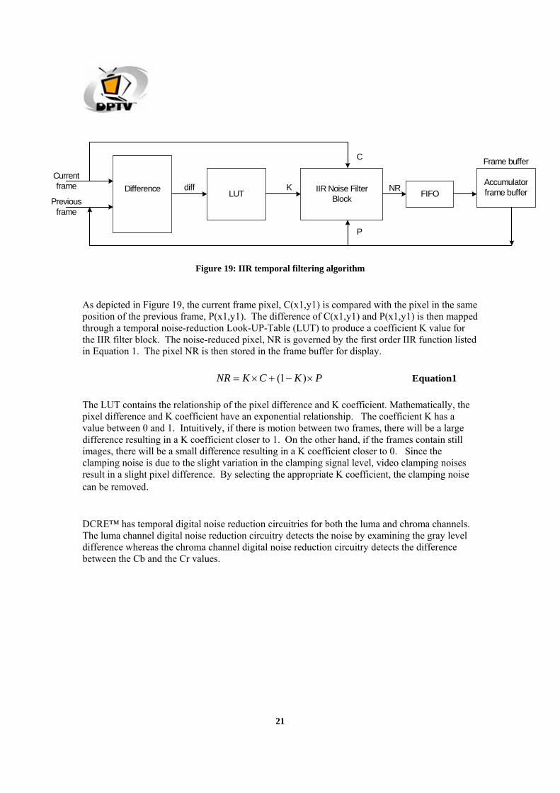
Figure 19: IIR temporal filtering algorithm
As depicted in Figure 19, the current frame pixel, C(x1,y1) is compared with the pixel in the same position of the previous frame, P(x1,y1). The difference of C(x1,y1) and P(x1,y1) is then mapped through a temporal noise-reduction Look-UP-Table (LUT) to produce a coefficient K value for the IIR filter block. The noise-reduced pixel, NR is governed by the first order IIR function listed in Equation 1. The pixel NR is then stored in the frame buffer for display.
PKCKNR ×−+×= )1( Equation1
The LUT contains the relationship of the pixel difference and K coefficient. Mathematically, the pixel difference and K coefficient have an exponential relationship. The coefficient K has a value between 0 and 1. Intuitively, if there is motion between two frames, there will be a large difference resulting in a K coefficient closer to 1. On the other hand, if the frames contain still images, there will be a small difference resulting in a K coefficient closer to 0. Since the clamping noise is due to the slight variation in the clamping signal level, video clamping noises result in a slight pixel difference. By selecting the appropriate K coefficient, the clamping noise can be removed.
DCRE™ has temporal digital noise reduction circuitries for both the luma and chroma channels. The luma channel digital noise reduction circuitry detects the noise by examining the gray level difference whereas the chroma channel digital noise reduction circuitry detects the difference between the Cb and the Cr values.

22
7. DETI–Digital Enhanced Transient Improvement and RGB Color Management
Gray Level
Standard Gamma Curve
Make highcontrast atdark level.
(a) Dark image (gamma low)
Rel
ativ
e B
right
ness
Leve
by
APL
Gray Level
StandardGammaCurve
Make highcontrast atdark level.
Rel
ativ
e B
right
ness
Leve
by
APL
Make highcontrast atbright level.
(a) Bright image (gamma high)
Figure 20: DETI and RGB Color Management 8. Average Picture Level (APL) Read-back In the APL read back function, the average picture luminance level is read back on the real time basis. The APL allows the automatic adjustment of both brightness and contrast levels to achieve the most optimal image quality of a given scene. This feature improves the dynamic range of the LCD panel device. Figure 21 shows that the dynamic APL engine improves the image contrast level.

23
Figure 21: Average Picture level Read-back
9. Sharpness DCRe™ sharpness filters are for both vertical and horizontal directions in the image. In addition, the internal luminance transient improvement and peaking algorithm work in tandem to improve the local area picture sharpness. As shown in Figure 22 below, the picture becomes more crisp after the vertical and horizontal sharpness enhancement.
a. Without vertical and horizontalsharpness enhancement
b. Vertical and horizontal sharpness, DLTI, peaking allworking in together to improve sharpness and clarity.
Figure 22: Sharpness Enhancement
Dynamic APLEngine

24
10. LCD Overdrive LCD Overdrive improves the TFT-LCD panel response time so that the moving video picture quality is improved. LCD Overdrive uses the dynamic luminance boosting (DLB) method that controls the driving voltage from (A B) to (A C B) and thus improves the response time in the gray (luminance scale). DCRe™ utilizes the UMA architecture that uses the frame buffers to store current and previous field information needed for LCD Overdrive processing. In the DLB driving method, the current frame luminance Y_c is compared to the previous frame luminance Y_p value. A look up table is used to derive the gain value needed for target display response time, Y_t. The relationship is given below and depicted in Figure 23. Y_t = Y_c + (Y_c-Y_p) X Gain.
Y_t
Y_o
Y_p
Lum
inan
ce
Previous Current
Transition Time
Time
Figure 23: DLB Overdrive
The Y_p and Y_o are compared to the panel native transition time to calculate the Y_t, target panel response time. The visual LCD overdrive effects are shown in Figure below.