dcsc controllerweb.lamarchemfg.com/userfiles/instruction-manuals/... · 6.1.3 configuring an alarm...
TRANSCRIPT
This manual is subject to change without notice. You may obtain the newest version of the manual at www.lamarchemfg.com
106 Bradrock Dr. Des Plaines, IL 60018-1967 CPN 133203 Instruction Drawing Number: P25-LDCSC-CNTR-1 Tel: 847 299 1188 Fax: 847 299 3061 Revision A02 Rev. Date: 02/17 ECN: 21357
La Marche Manufacturing Company www.lamarchemfg.com
DCSC ControllerDC System Controller
Installation and Operation Manual

About This Document
Purpose
This document describes the site monitoring unit DCSC in terms of its hardware, liquid crystal display (LCD), web user interface (WebUI), common operations, remote management, and features.
Intended Audience
This document is intended for:
Sales engineers
Technical support personnel
Maintenance personnel
Symbol Conventions The symbols that may be found in this document are defined as follows.
Symbol Description
Indicates an imminently hazardous situation which, if not avoided, will result in death or serious injury.
Indicates a potentially hazardous situation which, if not avoided, could result in death or serious injury.
Indicates a potentially hazardous situation which, if not avoided, may result in minor or moderate injury.
Indicates a potentially hazardous situation which, if not avoided, could result in equipment damage, data loss, performance deterioration, or unanticipated results.
NOTICE is used to address practices not related to personal injury.
Calls attention to important information, best practices and tips.
Symbol Description
NOTE is used to address information not related to personal injury, equipment damage, and environment deterioration.

Contents
Contents
About This Document .................................................................................................................... ii
1 Overview ......................................................................................................................................... 1 1.1 Introduction ........................................................................................................................................................................... 1
1.2 Features .................................................................................................................................................................................. 4
2 Panels and Ports ............................................................................................................................. 5 2.1 DCSC. ......................................................................................................................................................................................... 5
2.2 DCU Panel ........................................................................................................................................................................ 6
3 Hardware Replacement .............................................................................................................. 9 3.1 Safety Precautions .......................................................................................................................................................... 9
3.2 Replacing the DCSC ..................................................................................................................................................... 9
3.3 Replacing the DCU ....................................................................................................................................................... 10
4 LCD .................................................................................................................................................. 12 4.1 LCD Menu Hierarchy ..................................................................................................................................................... 12
4.2 Buttons ................................................................................................................................................................................. 13
4.3 Password .............................................................................................................................................................................. 13
5 WebUI............................................................................................................................................ 14 5.1 Preparations for Login .................................................................................................................................................... 14
5.1.1 Preparing the Operating Environment ........................................................................................................................ 14
5.1.2 Connecting a Communications Cable ......................................................................................................................... 14
5.1.3 Setting Parameters ....................................................................................................................................................... 15
5.2 Login Page ...................................................................................................................................................................... 15
5.3 Running Info ................................................................................................................................................................... 16
5.4 Setting .................................................................................................................................................................................. 16
5.5 Control ................................................................................................................................................................................. 19
5.6 Historical Data ................................................................................................................................................................ 20
5.7 Maintenance ........................................................................................................................................................................ 21
6 Common Tasks ............................................................................................................................ 24 6.1 Common Installation Tasks ....................................................................................................................................................... 24
6.1.1 Setting Basic Battery Parameters ................................................................................................................................ 24

Contents
6.1.2 Setting the Date and Time ........................................................................................................................................... 25
6.1.3 Configuring an Alarm Tone ................................................................................................................................................... 26
6.1.4 Enabling or Disabling Alarms ..................................................................................................................................... 27
6.1.5 Setting Alarm Severities .............................................................................................................................................. 28
6.1.6 Setting Alarm Associated Relays ................................................................................................................................ 29
6.1.7 Setting Alarm Action for Dry Contact Output ............................................................................................................ 29
6.1.8 Setting Alarm Conditions for Dry Contact Inputs ...................................................................................................... 30
6.2 Common Maintenance Tasks .................................................................................................................................................... 33
6.2.1 Backing Up the Current Settings ................................................................................................................................ 33
6.2.2 Restoring Factory Defaults ......................................................................................................................................... 34
6.2.3 Upgrading the Software .............................................................................................................................................. 34
6.2.4 Rebooting the Controller ............................................................................................................................................. 35
6.2.5 Adding or Deleting Users ............................................................................................................................................ 35
6.2.6 Changing the User Password ...................................................................................................................................... 36
6.2.7 Querying Active Alarms ............................................................................................................................................. 38
6.2.8 Querying and Clearing Historical Alarms .................................................................................................................. 39
6.2.9 Clearing the Rectifiers Failing in Communication ..................................................................................................... 39
6.2.10 Manually Controlling a Power System ..................................................................................................................... 40
7 Remote Management .................................................................................................................. 42 7.1 NMS Management over SNMP ..................................................................................................................................... 42
7.1.1 NetWork Configuration ............................................................................................................................................... 42
7.1.2 Setting SNMP Parameters ........................................................................................................................................... 43
8 Feature Description ..................................................................................................................... 46 8.1 Rectifier Management .................................................................................................................................................... 46
8.1.1 (Optional) Starting Rectifiers Sequentially ................................................................................................................ 46
8.2 Energy Conservation Management ................................................................................................................................ 47
8.2.1 Intelligent Rectifier Hibernation ................................................................................................................................. 47
8.3 Power Segment Management ......................................................................................................................................... 51
8.4 Lead-Acid Battery Management .................................................................................................................................... 55
8.4.1 Charging Management ................................................................................................................................................ 55
8.4.2 Temperature Compensation ........................................................................................................................................ 59
8.4.3 Standard Battery Test .............................................................................................................................................................. 62
8.4.4 Intelligent Battery Hibernation ................................................................................................................................... 66
8.5 Programmable Logic Controller .................................................................................................................................... 67
8.6 Performance Statistics .................................................................................................................................................... 73
A LCD Menu Hierarchy ................................................................................................................ 77

1 Overview
1.1 Introduction The site monitoring unit DCSC is a compact high-end monitoring module that monitors and manages La Marche box-type and cabinet-type power systems.
You can access the DCSC over the WebUI or a third-party network management system (NMS) that supports the SNMP to remotely manage power systems at multiple sites.
By configured with the user interface module DCU, the DCSC provides sensor ports, a RS485 port, dry contact inputs, and dry contact outputs for managing the environment inside the cabinet and reporting alarms.
Figure 1-1 shows a DCSC, Figure 1-2 shows a DCU, Figure 1-3 shows the connections between the DCSC, DCU, and system interface board. Figure 1-4 shows the connections between the DCSC, power system components, and NMSs.
Figure 1-1 DCSC
Figure 1-2 DCU

Figure 1-3 Connections between the DCSC and theDCU

Figure 1-4 Network between the DCSC, power system components, and EMSs

1.2 Features The DCSC has the following features:
Monitors the power system operating status in real time.
− Monitors AC and DC information.
− Monitors rectifier information.
− Monitors battery information.
− Monitors ambient temperatures, battery temperatures, ambient humidity, door status, smoke generation, and water intrusion.
− Detects the status of six dry contact inputs.
Detects and reports alarms in real time.
− There are four alarm severities, critical, major, minor, and warning, which can be associated with dry contact outputs. If the DCU is configured, eight dry contact outputs are supported.
− Informs users of alarms by the indicators and alarm sounds that can be enabled.
− Saves 50,000 historical alarms.
Supports multiple remote management modes.
− Over the WebUI.
− Over an NMS that supports SNMP.
Supports flexible rectifier management.
− Controls rectifier output voltages.
− Controls rectifier output currents.
− Starts or shuts down each rectifier.
Supports effective energy conservation management.
Intelligent rectifier hibernation management.
Supports comprehensive battery management.
− Battery equalized charging and float charging management
− Battery fast charging management.
− Battery temperature compensation.
− Battery high temperature protection.
− Battery test management.
− Battery current limiting management.
− Battery low voltage disconnection (BLVD) protection.
− Battery presence and balance detection.
Supports flexible and programmable logic control.
Selects any signals (such as those indicating DC under voltage, rectifier missing, and AC power failures) and performs logical operations on them, such as AND, OR, NOT, >, <, and then sends calculation results to reserved dry contacts.
Supports data export and performance statistics collection.

2 Panels and Ports
2.1 DCSC
Figure 2-1 DCSC panel
(1) Run indicator (2) Minor Alarm indicator (3) Major Alarm indicator
(4) Buttons (5) USB port (reserved) (6) RS485/RS232 port
(7) Handle (8) Locking latch (9) Fast Ethernet (FE) port
(10) LCD
Table 2-1 DCSC indicator description
Indicator Color Status Description
Run indicator Green Off The DCSC is faulty or has no DC input.
Blinking at 0.5 Hz
The DCSC is running properly and communicating with the host properly.
Blinking at 4 Hz
The DCSC is running properly but is not communicating with the host
lMinor Alarm indicator
Yellow Off The DCSC is not generating any minor alarms.
Steady on The DCSC is generating a minor alarm.
Major Alarm indicator
Red Off The DCSC is not generating any critical or major alarms.
Steady on The DCSC is generating a critical or major alarm.

LCD
The DCSC provides a 128x48 LCD with white backlight to display real-time parameters for you to view and set. The visible area dimensions (L x W) are 34.54 mm x 11.02 mm.
USB Port
The DCSC reserves a USB port.
Communications Ports
Table 2-2 DCSC communications port description
Communications Port Communications Parameter Communications Protocol
FE port 10/100M autonegotiation HTTPS and SNMP
Figure 2-2 Pins in a communications port Table 2-3 FE port pin definition
2.2 DCU Panel
Panel
Figure 2-3 DCU panel
Pin Signal Description
1 TX+ Sends data over FE.
2 TX-
3 RX+ Receives data over FE.
6 RX-
4, 5, 7, and 8 Left blank -

Ports
Table 2-4 DCU port description
Port Type Silk Screen Description
Sensor port TEM-HUM Ambient temperature and humidity sensor
WATER Water sensor
TEMP1 Ambient temperature sensor 1
TEMP2 Ambient temperature sensor 2
GATE Door status sensor
SMOKE Smoke sensor
BTEMP Battery temperature sensor
Dry contact input
NOTE For details about the signal definitions, see the power system user manual.
DIN1 Dry contact input 1
DIN2 Dry contact input 2
DIN3 Dry contact input 3
DIN4 Dry contact input 4
DIN5 Dry contact input 5
DIN6 Dry contact input 6
Dry contact output
NOTE For details about the alarms associated with dry contact outputs, see the power system user manual.
ALM1 Dry contact output 1
ALM2 Dry contact output 2
ALM3 Dry contact output 3
ALM4 Dry contact output 4
ALM5 Dry contact output 5
ALM6 Dry contact output 6
ALM7 Dry contact output 7
ALM8 Dry contact output 8
Communications port COM RS485 port

Pins
Figure 2-4 DCU pin numbers
Table 2-5 DCU pin definitions
Silk Screen No. Pins
TEM-HUM 1 12 V
2 ENV_TEMP
3 12 V
4 ENV_HUM
WATER 1 12 V
2 WATER
3 GND
4 -
TEMP1 1 TEMP1
2 GND
TEMP2 1 TEMP2
2 GND
GATE 1 GATE-
2 GATE+
SMOKE 1 12V
2 SMOKE
BTEMP 1 BTEMP1
2 GND

3 Hardware Replacement
3.1 Safety Precautions
When replacing the DCSC and user interface module (DCU), wear electrostatic discharge (ESD) gloves or an ESD wrist strap to avoid component damage.
3.2 Replacing the DCSC
Context
The DCSC is hot-swappable.
Procedure
Step 1 Push the locking latch on the DCSC to the left and pull out the handle.
Step 2 Take the DCSC out of the slot, as shown in Figure 3-1.
Figure 3-1 Removing the DCSC
Step 3 Place the new DCSC at the entry to the appropriate slot in the monitoring unit subrack, and push the DCSC until its front panel aligns with the front panel of the monitoring unit subrack.
Step 4 Push the handle in position and push the locking latch to the right to lock the handle, as shown in Figure 3-2.
Figure 3-2 Installing the DCSC

Follow‐up Procedure
After replacing the DCSC, the parameters are restored to factory defaults. You need to reset the parameters based on site requirements.
3.3 Replacing the DCU
Procedure
Step 1 Record the positions where signal cables connect to the DCU panel, and then disconnect the signal cables.
Step 2 Loosen the screws on the DCU panel and remove the DCU.
Figure 3-3 Removing the DCU

Step 3 Disconnect the 48 V power cable from the DCU backplane.
Figure 3-4 Disconnecting the 48 V power cable
Step 4 Disconnect the flat cable from the DCU backplane.
Step 5 Take out a new DCU, and connect the flat cable to the new DCU backplane.
Step 6 Connect the 48 V power cable to the new DCU backplane.
Step 7 Push the DCU into the slot until its front panel aligns with the front panel of the monitoring unit, and tighten the screws.
Step 8 Connect the signal cables to the original positions on the DCU panel.

4 LCD
4.1 LCD Menu Hierarchy
Figure 4-1 LCD menu hierarchy

The # means that the menu is displayed when the associated equipment is connected or associated
parameter is set.
For details about how to set parameters, see appendix.
4.2 Buttons
The DCSC provides four buttons to set and query parameters.
Table 4-1 Button description
4.3 Password
When visiting Setting Wizard, Parameters Settings, and Running Control on the LCD, enter the preset password 000001.
Change the default password upon your first login to ensure the system security. 6.2.6 Changing the User Password describes how to change the password.
Preset user name: admin
Preset password:
Button Name Description
Up Press Up and Down to scroll through the menus or
to change the value of a parameter.
Down
Cancel Returns to the previous menu without saving the
settings.
Enter Enters the main menu from the standby screen. Enters a submenu from the main menu. Saves menu settings on a submenu.
NOTE The LCD screen becomes dark if no button is pressed within 30 seconds.
You need to log in again if no button is pressed within 1 minute.
To increase or decrease the parameter value quickly, hold down or .
To restart the DCSC, hold down and at the same time for 10 seconds.
Hold down and (or ) for more than 2 seconds to increase (or decrease) the LCD backlight brightness.
Changeme

FE port
5 WebUI
5.1 Preparations for Login 5.1.1 Preparing the Operating Environment
Operating system: Windows XP or later
Browser: Internet Explorer 7.0 or later, FireFox 5.0 or later, and Chrome 16.0 or later
5.1.2 Connecting a Communications Cable
Procedure
Step 1 Connect the FE port on the DCSC by using a network cable.
Figure 5-1 Connecting a Communications Cable

5.1.3 Setting Parameters
Procedure
Step 1 Apply to the site or equipment room network administrator for a fixed IP address.
Step 2 Set the IP address, subnet mask, and gateway on the LCD. Table 5-1
Main Menu Second-Level Menu
Third-Level Menu
Default Value
Setting Value
Setting Wizard Network Parameters
IP Address 192.168.0.10 Set this parameter according to the address assigned by the network administrator.
Subnet Mask 255.255.255.0 Set this parameter according to the subnet mask provided by the network administrator.
Default Gateway
192.168.0.0 Set this parameter according to the gateway address provided by the network administrator.
5.2 Login Page
Enter the IP address for the DCS in the address box of Internet Explorer. The login page is displayed. Default user name: admin Default password: Changeme
Figure 5-2
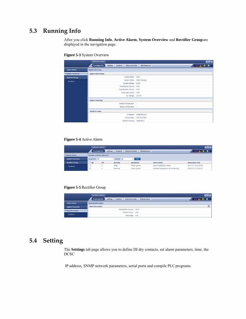
5.3 Running Info
After you click Running Info, Active Alarm, System Overview and Rectifier Group are displayed in the navigation page.
Figure 5-3 System Overview
Figure 5-4 Active Alarm
Figure 5-5 Rectifier Group
5.4 Setting
The Settings tab page allows you to define DI dry contacts, set alarm parameters, time, the DCSC
IP address, SNMP network parameters, serial ports and compile PLC programs.

Setting System Parameters
The System Configuration page allows you to set basic, threshold, rectifier, charge, and battery parameters.
Figure 5-6 System Configuration
Setting Alarm Parameters
The Alarm Parameters page allows you to view alarm information based on the device type, to enable or disable alarm generation, and to set alarm severities and alarm dry contact outputs based on site requirements.
Figure 5-7 Alarm Parameters
Setting Dry Contact Parameters
The Dry Contact Parameters page allows you to set alarm severities, DI dry contact parameters, and alarm dry contact parameters.
Figure 5-8 Dry Contact Parameters

Setting PLC
The PLC page allows you to select any signals (such as those indicating DC undervoltage, D.G. operating, and AC power failures) and perform logical operations on them, such as AND, OR, NOT, >, and <, and then send calculation results to dry contacts.
Figure 5-9 PLC
Setting Network Configuration
The Network Configuration page allows you to set the IP address, subnet mask, and default gateway.
Figure 5-10 Network Configuration
Setting SNMP
The SNMP page allows you to set SNMP network parameters and export Mib files.
Figure 5-11 SNMP

Setting Date and Time
The Date and Time page allows you to set a time zone and local time. You can directly set the local date and time or synchronize the time with that on the Network Time Protocol (NTP) server.
Figure 5-12 Date and Time
5.5 Control
The Control page allows you to control the power system and its components, such as the rectifier and battery.
Figure 5-13 Control

5.6 Historical Data
The Historical Data tab page allows you to query and export historical alarms, performance data and battery test records.
Querying Historical Alarm
The Historical Alarm page allows you to query the alarm information about one or all devices based on the device type.
Figure 5-14 Historical Alarm
Querying Performance Data
The Performance Data page allows you to query system parameters, such as ambient temperatures, system voltages, and battery parameters based on the device type.
Figure 5-15 Performance Data
Exporting Data
The Export Data page allows you to export historical alarms, performance data, operation records, and battery test records respectively or as a whole.
Figure 5-16 Export Data

5.7 Maintenance
The Maintenance tab page allows you to upgrade the system, query version information, import and back up configuration files, query component electronic labels, manage users, and export fault information.
Upgrading Software
The Software Upgrade page allows you to select an upgrade file and upgrade the software.
Figure 5-17 Software Upgrade
Querying Version Information
The Version Information page allows you to query the software version, hardware version, and bottom support program (BSP) version of the power system and its components.
Figure 5-18 Version Information
Setting Configuration Files
The Configuration File page allows you to import configuration files, back up current configurations, and restore the factory defaults.

Figure 5-19 Configuration File
Managing Users
The User Management page allows you to add, modify, and delete users.
Figure 5-20 User Management
The DCSC supports a maximum of three online users. User types are classified into admin, engineer, developer (Factory use only) and operator, and they have different rights.
You can manage users only on the WebUI. Exporting Fault Information
The Fault Information page allows you to export fault information in one-click mode.
Figure 5-21 Fault Information
6 Common Tasks
6.1 Common Installation Tasks 6.1.1 Setting Basic Battery Parameters
Context
Basic battery parameters are the criteria for battery management and need to be set based on the actual number of battery strings and battery capacity.
Incorrect setting of basic battery parameters affects battery charge and discharge management and reduces the battery lifespan.
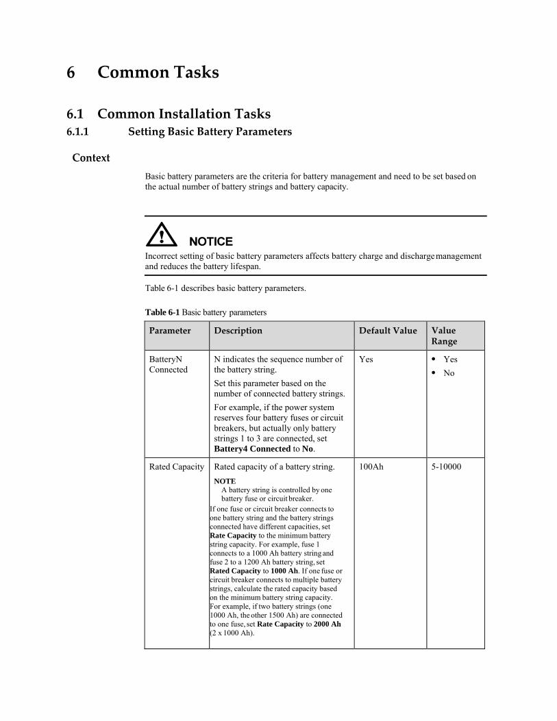
Table 6-1 describes basic battery parameters.
Table 6-1 Basic battery parameters
Parameter Description Default Value Value Range
BatteryN Connected
N indicates the sequence number of the battery string.
Set this parameter based on the number of connected battery strings.
For example, if the power system reserves four battery fuses or circuit breakers, but actually only battery strings 1 to 3 are connected, set Battery4 Connected to No.
Yes Yes No
Rated Capacity Rated capacity of a battery string.
NOTE A battery string is controlled by one battery fuse or circuit breaker.
If one fuse or circuit breaker connects to one battery string and the battery strings connected have different capacities, set Rate Capacity to the minimum battery string capacity. For example, fuse 1 connects to a 1000 Ah battery string and fuse 2 to a 1200 Ah battery string, set Rated Capacity to 1000 Ah. If one fuse or circuit breaker connects to multiple battery strings, calculate the rated capacity based on the minimum battery string capacity. For example, if two battery strings (one 1000 Ah, the other 1500 Ah) are connected to one fuse, set Rate Capacity to 2000 Ah (2 x 1000 Ah).
100Ah 5-10000
LCD Operation
Step 1 Set Battery1 Connected to Yes.
Path: Setting Wizard > Battery Parameters > Battery1 Connected
Step 2 Set the Rated Capacity based on the actual requirements.
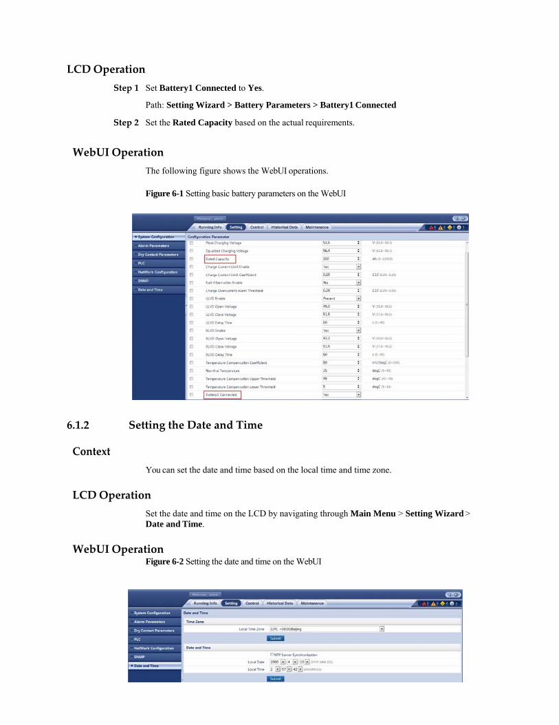
WebUI Operation
The following figure shows the WebUI operations.
Figure 6-1 Setting basic battery parameters on the WebUI
6.1.2 Setting the Date and Time
Context
You can set the date and time based on the local time and time zone.
LCD Operation
Set the date and time on the LCD by navigating through Main Menu > Setting Wizard > Date and Time.
WebUI Operation
Figure 6-2 Setting the date and time on the WebUI

6.1.3 Configuring an Alarm Tone
Context
You can configure an alarm tone over the LCD or WebUI.
When the buzzer sounds, press any button on the DCSC panel to suspend it.
Table 6-2 Alarm tone parameter description
Parameter Description Default Value Value Range
Buzzer Enable Enables or disables an alarm tone.
No Yes No
LCD Operation
Step 1 Set Buzzer Enable to Yes.
Path: Parameters Settings > Power System > Basic Parameters > Buzzer Enable
WebUI Operation
Step 1 Set Buzzer Enable to Yes.
Figure 6-3 Setting Buzzer Alarm Duration on the WebUI

6.1.4 Enabling or Disabling Alarms
Context
You can enable or disable each alarm based on site requirements.
If an alarm is enabled, the DCSC generates the alarm when the alarm condition is met.
If an alarm is disabled, the DCSC does not generate the alarm even though the alarm condition is met.
LCD Operation
Step 1 Set Alarm Enable to Yes.
Path: Parameters Settings > Alarm Parameters > Alarm Parameters
WebUI Operation
Step 1 Select an equipment type.
Figure 6-4 Selecting an equipment type on the WebUI
Step 2 Enable alarms on the alarm list corresponding to Power System.
Figure 6-5 Enabling alarms on the WebUI

Figure 6-6 Selecting an equipment type on the WebUI
6.1.5 Setting Alarm Severities
Context
There are four alarm severities: critical, major, minor, and warning.
You can set a severity for each alarm.
LCD Operation
Step 1 Set alarm severities based on the site requirements.
Path: Parameters Settings > Alarm Parameters > Alarm Parameters
WebUI Operation
Step 1 Select an equipment type.
Step 2 Set severities for the alarms on the alarm list corresponding to Power System.
Figure 6-7 Setting alarm severities on the WebUI.

6.1.6 Setting Alarm Associated Relays
LCD Operation
Path: Parameters Settings > Alarm Parameters > Alarm Parameters
WebIU Operation
Step 1 Select an equipment type.
Figure 6-8 Selecting an equipment type on the WebUI
Step 2 Associate alarms with dry contact outputs on the alarm list corresponding to Power System.
Figure 6-9 Setting alarm associated relays on the WebUI
6.1.7 Setting Alarm Action for Dry Contact Output
Context
You can set associations between dry contact output status and alarm status. The default association is as follows: If an alarm is generated, the dry contact output is open; if no alarm is generated, the dry contact output is closed.
LCD Operation
Path: Parameters Settings > Alarm Parameters > DO Dry Contact Para.

WebUI Operation
Figure 6-10 Setting alarm actions on the WebUI
6.1.8 Setting Alarm Conditions for Dry Contact Inputs
Context
You can set associations between dry contact input status and alarm status. Take the DIN1 as an example. If you set the DIN1 Alarm Condition to Close, the DCU generates a DIN1 Alarm when the DIN1 is closed.
LCD Operation
Path: Parameters Settings > Alarm Parameters > DI Dry Contact Para. WebUI Operation
Figure 6-11 Setting alarm conditions for dry contact inputs on the WebUI

6.2 Common Maintenance Tasks 6.2.1 Backing Up the Current Settings
Context
The configuration file contains all the modified configurations for the current system type, such as parameter values and alarm configurations.
You can back up the configuration file to a local computer over the WebUI.
WebUI Operation
Figure 6-17 Backing up the current configuration file on the WebUI

6.2.2 Restoring Factory Defaults
After factory defaults are restored, the DCSC restarts.
After factory defaults are restored, all parameter values change to the default values before delivery. Therefore, you are advised to back up the current configuration file before restoring factory defaults.
You can restore factory defaults over the WebUI. Operator users have no such permission. WebUI Operation
Figure 6-18 Restoring factory defaults on the WebUI
6.2.3 Upgrading the Software
Context
You can upgrade the software for the DCSC and rectifiers on the WebUI. It takes two minute to upgrade the DCSC. Time for upgrading the rectifiers relates to the number of rectifiers.
After the software is upgraded, the DCSC restarts.
WebUI Operation
Figure 6-19 Upgrading the software on the WebUI

6.2.4 Rebooting the Controller
Context
Resetting the DCSC takes about one minute. During the resetting, the DCSC cannot monitor and manage connected rectifiers, batteries, and other devices. After the DCSC is reset, the configuration file used before the resetting, is automatically loaded. You do not have to reset parameters.
LCD Operation
Set Reboot Controller to Yes on the LCD by navigating through Running Control > Power System > Reboot Controller.
WebUI Operation
Step 1 Select Reboot Controller and Click Submit.
Figure 6-20 Rebooting Controller on the WebUI
6.2.5 Adding or Deleting Users
Context
The DCSC supports a maximum of three online users. User types are classified into admin, engineer, and operator. Table 6-3 describes the rights of the three user types.
After version rollback, the user accounts created are deleted, and the initial user name and password are required for login.
You can set user types only on the WebUI.

Table 6-3 User types and rights
User Type User Rights Maximum Number of Users
Admin Have the rights of viewing, setting, and controlling all attributes and functions.
15 in total
Engineer Have the same rights as admin users except the right of user management.
Operator Have the rights of viewing real-time monitoring information, querying historical data and electronic labels, setting time and IP addresses, configuring data record parameters, backing up configuration files, and exporting faulty information.
WebUI Operation
Figure 6-21 User management on the WebUI
6.2.6 Changing the User Password
Context
To ensure the system security, you are advised to change the password periodically.
Only the system administrator has the right of changing the user password.
LCD Operation
Change the password in compliance with the following principles:

Six characters are required.
The password consists of digits, uppercase letters and lowercase letters.
Path: Parameters Settings > Local Parameters > Change Password
WebUI Operation
Step 1 After you log in to the WebUI, choose Maintenance > User Management to enter the user management page.
Figure 6-22 User management WebUI
Step 2 Select the user whose password needs changing and click Modify.
A dialog box is displayed.
Figure 6-23 Changing the user password on the WebUI.

Step 3 Enter Old Password, New Password, and Confirm Password and click Confirm.
The administrator needs to enter the Old Password only when changing its own password.
Change the password in compliance with the following principles:
Six characters are required.
At least two types of the following are required in the password, digits, uppercase letters, lowercase letters, or special characters (` ~ !@ # $ % ^ & * - _ =+ ; :'",.? or spacing).
The new password should be different from the old one.
The password cannot be the same as the user name or its reverse.
6.2.7 Querying Active Alarms
Context
Active alarms are the alarms that are not cleared.
LCD Operation
Choose Active Alarm on the LCD to view active alarms.
WebUI Operation
Figure 6-24 Querying active alarms on the WebUI.

6.2.8 Querying and Clearing Historical Alarms
Context
Historical alarms refer to alarms that have been cleared.
LCD Operation
Set Delete His. Alarms to Yes in the Running Control > Clear Alarm > Historical Alarm > Delete His. Alarms path.
Query historical alarms in the Running Control > Clear Alarm > Historical Alarm > Active Alarm path.
WebUI Operation
Figure 6-25 Querying and clearing historical alarms on the WebUI
6.2.9 Clearing the Rectifiers Failing in Communication
Context
After you remove one or more rectifiers, the DCSC generates a communication failure alarm. If you confirm that the rectifiers do not need to be reinstalled, clear the configuration information about the removed rectifiers over the LCD or WebUI.

LCD Operation
Set Rectifier Re-configuration to Yes on the LCD by navigating through Running Control > Rectifier > Rectifier Group.
WebUI Operation
Step 1 Choose Control, on the Rectifier Control page, select Rectifier Re-configuration and Submit, as show in Figure 6-26.
Figure 6-26 Clearing rectifiers failing in communication on the WebUI
6.2.10 Manually Controlling a Power System
You can control a power system manually or automatically.
Automatic mode
This is the default mode. The DCSC automatically controls a power system based on the system configuration.
Manual mode
You manually control a power system over the DCSC, such as starting or shutting down rectifiers. After remaining in the Manual mode for two hours, the controller automatically changes back to the Automatic mode.
Starting and Shutting Down Rectifiers
Context
Exercise caution when shutting down rectifiers, because such operation will decrease the maximum output power and may disconnect the power supply to loads.
You can manually start or shut down rectifiers only in manual mode.

Parameters
Table 6-4 Rectifier startup/shutdown parameter description
Parameter Description Default Value Value Range
Turn on/off Rectifier
Controls the startup and shutdown for a single rectifier.
On On
Off
LCD Operation
Step 1 Set System Control Mode to Manual.
Path: Running Control > Power System > System Control Mode
Step 2 Set Turn on/off to On or Off.
Path: Running Control > Rectifier > Rectifier1 > Turn on/off
WebUI Operation
To control the startup and shutdown for rectifiers, perform the following steps:
Step 1 Set System Control Mode to Manual and click Submit.
Step 2 Select Rectifier from the drop-down list box, set Turn on/off Rectifier to On or Off and click Submit to start or shut down a single rectifier. Figure 6-27 shows the page for starting a single rectifier.
Figure 6-27 Starting a single rectifier on the WebUI

7 Remote Management
7.1 NMS Management over SNMP 7.1.1 NetWork Configuration
Connecting a Communications Cable
Procedure
Step 1 Connect the FE port on the DCSC by using a network cable, as shown in Figure 7-1.
Figure 7-1 Connecting a Communications Cable
(1) FE port (2) GPRS Modem

Setting Parameters
Procedure
Step 1 Apply to the site or equipment room network administrator for a fixed IP address.
Step 2 Set the IP address, subnet mask, and gateway on the LCD, as shown in Table 7-1.
Table 7-1 IP parameters
Main Menu
Second‐Level Menu
Third‐Level Menu
Default Value
Setting Value
Setting Wizard
Network Parameters
IP Address 192.168.0.10 Set this parameter according to the address assigned by the network administrator.
Subnet Mask 255.255.255.0 Set this parameter according to the subnet mask provided by the network administrator.
Default Gateway 192.168.0.1 Set this parameter according to the gateway address provided by the network administrator.
7.1.2 Setting SNMP Parameters
Prerequisites
You can set SNMP parameters on the WebUI locally or remotely.
Before setting SNMP parameters, obtain the information listed in Table 7-2 from the EMS.
Table 7-2 Information obtained from the EMS
Information Description
SNMP version SNMP version and port number used by the DCSC and EMS. The SNMP versions include SNMPv1, SNMPv2c, and SNMPv3.
SNMP Port Number

Procedure
Step 1 Enter the IP address for the DCSC in the address box of Internet Explorer. Log in to the WebUI on the login page shown in Figure 7-2.
The preset user name is admin and preset password is Changeme.
Figure 7-2 Login page
Step 2 On the System Settings tab page, select SNMP.
If the SNMP version is SNMPv1 or SNMPv2, set SNMP Version to SNMPv1&SNMPv2c under SNMP, and then set SNMP Port Number, Read Community Name, and Write Community Name, as shown in Figure 7-3.
Information Description
Read Community Name If you use SNMPv1 or SNMPv2c, enter the read community name and write community name that comply with the EMS. Otherwise, the DCSC will not connect to the EMS.
Write Community Name
User Name To enhance the security, you need a user name and password for authentication if you use SNMPv3. After the authentication succeeds, the DCSC can communicate with the EMS.
MD5 Password
DES Password
Trap Target Address IP address and port number reported in the alarm trap.
Trap Port

Figure 7-3 Setting SNMPv1 and SNMPv2c parameters
If the SNMP version is SNMPv3, set SNMP Version to SNMPv3 under SNMP, click
Add under SNMPv3, and then set User Name, MD5 Password, and DES Password.
Figure 7-4 Setting SNMPv3 parameters
Step 3 Under SNMP Trap, set TrapTarget Address and Trap Port.
Step 4 Under Mib files, click Export to export the Mib file and import it to the EMS.
If there is only one EMS, perform Step 4 once.

8 Feature Description
8.1 Rectifier Management 8.1.1 (Optional) Starting Rectifiers Sequentially
Principles
Rectifiers start one by one based on the preset time interval, which avoids the impact on batteries and rectifier input circuit breakers.
This function applies only to the rectifiers that communicate over CAN.
Parameters
Table 8-1 Parameter description for sequential rectifier startup
Parameters Description Default Value Value Range
Sequential Start Interval Time interval between the rectifiers that are started sequentially
0s 0–20
LCD Operation
Setting Sequential St. Int. on the LCD UI Parameters Settings > Rectifier.
WebUI Operation
Figure 8-1 Setting Sequential Start Interval on the WebUI

8.2 Energy Conservation Management 8.2.1 Intelligent Rectifier Hibernation
The rectifier efficiency increases in proportion to the load power. If the total load power is low, certain rectifiers can hibernate to improve the load power of running rectifiers and increase the rectifier efficiency. This facilitates energy conservation. In addition, rectifier service life is prolonged because rectifier runtime is reduced. Figure 8-2 shows a rectifier efficiency curve.
Figure 8-2 R4850G1 efficiency curve
The DCSC controls the rectifier startup and hibernation based on the loading capacity of the power system. If the load power decreases, the DCSC puts certain rectifiers into hibernation. If the load power increases, the DCSC starts rectifiers to meet load power requirements. To ensure that all rectifiers deteriorate to the same degree, the DCSC puts different rectifiers into or out of hibernation alternately based on their real-time efficiency and runtime. See Figure 8-3.
Figure 8-3 Rectifier hibernation periods.

If the power system experiences an exception (such as battery loop disconnection, battery overtemperature, and AC exceptions), all rectifiers stop hibernation. The rectifiers start hibernation again after the exception is rectified. If the exceptions persist and rectifiers exist hibernation from time to time, the DCSC disables the rectifier hibernation function. After the Hibernation Stop Duration expires, the rectifiers start hibernation again.
Parameters
Table 8-2 Parameter description for intelligent rectifier hibernation
Parameter Description Default Value
Value Range
Rectifier Hibernation Enable
No: Hibernation is disabled Yes: The DCSC puts rectifiers
into hibernation when the hibernation condition is met.
No Yes No
Hibernation Mode
NOTE This parameter is displayed and valid only when Hibernation Enable is Yes.
Time Mode: Rectifiers with shorter runtime take precedence for work.
High Efficiency Mode: Rectifiers with higher real-time efficiency take precedence for work.
Intelligent Mode: The DCSC puts rectifiers into hibernation based on the runtime and real-time efficiency.
Intelligent Mode
Intelligent Mode
Time Mode
High Efficiency Mode
Minimum Working Rectifiers
NOTE This parameter is displayed
The minimum number of operating rectifiers after hibernation is enabled
2 1–100

Parameter Description Default Value
Value Range
and valid only when Hibernation Enable is Yes.
Circulation Period
NOTE This parameter is displayed and valid only when Hibernation Enable is Yes.
Period for alternating hibernated rectifiers with unhibernated rectifiers. At the end of the period, the DCSC starts all rectifiers and make them run for 2 hours, and then hibernate rectifiers again.
7 Day 1–365
Best Efficiency Point
NOTE This parameter is displayed and valid only when Hibernation Enable is Yes.
Percentage of rectifier loading capacity to rated capacity, at which the rectifier reaches its highest efficiency.
80% 50–100
Min. Redundant Coefficient
NOTE This parameter is displayed and valid only when Hibernation Enable is Yes.
Ratio of the minimum redundant current to the rated rectifier current
For example, if the rated rectifier current is 50 A and you need a 10 A redundant current, set Min. Redundant Coefficient to 0.2 (10 A/50 A).
0.20 0.05–1.00
Phase Balance
NOTE This parameter is displayed and valid only when Hibernation Enable is Yes.
In a three-phase power system, if the configuration of rectifiers meets the three-phase balance requirement, and intelligent rectifier hibernation is enabled, rectifiers corresponding to the three phases try to hibernate. Absolute Balance: The working
rectifiers corresponding to any two phases must be of the same quantity.
Relative Balance: The quantity difference between the working rectifiers corresponding to any two phases must be less than or equal to 1.
Disable Disable Relative
Balance
Absolute Balance
Hibernation Without Battery
NOTE
Indicates whether to enable hibernation when batteries are not connected.
NOTICE If you enable hibernation when batteries do not
No Yes
No

Parameter Description Default Value
Value Range
This parameter connect to the power system, the loads may is displayed experience power failures. Exercise cautionand valid only when performing this function.when Hibernation Enable is Yes.
Hibernation All rectifiers exit from hibernation if the 72.0 h 0.5–168.0 Stop Duration power system experiences an exception.
NOTE This parameter is displayed and valid only
After the exception is eliminated, the duration preset by Hibernation Stop Duration starts. After the duration expires, rectifiers try to hibernate again.
when Hibernation Enable is Yes.
Sequential Start Interval
Time interval between the rectifiers that are started sequentially
0 s 0–20
WALK-IN Enable
Enables or disables rectifier walk-in. No Yes, No
LCD Operation
LCD operation navigation path: Parameters Settings > Rectifier. WebUI Operation
Figure 8-4 Hibernating rectifiers intelligently

8.3 Power Segment Management When the system output power is insufficient due to the faulty AC input or rectifiers, batteries power the loads. To prolong the operating duration of primary loads and avoid reducing the battery lifespan due to overdischarge, the DCSC controls BLVD and LLVD based on preset power disconnection parameters.
After the AC input or the rectifiers are restored, the DCSC connects BLVD and LLVD routes again.
The power distribution design of the power system allows the DCSC to perform power segment. You can set disconnection parameters based on load type to disconnect secondary loads first, and then primary loads. This effectively extends the backup time for primary loads.
After the BLVD route is disconnected, the power system does not power loads.
You can disable BLVD, but batteries may be damaged due to overdischarge.
Figure 8-5 shows the hardware connections for power segment. Figure 8-6 shows the power segment logic diagram.

Parameters
Figure 8-5 Hardware connections for power segment
Figure 8-6 Power segment logic diagram
Table 8-3 BLVD parameter description
Parameter Description Default Value
Value Range
BLVD Enable Enable or disable the DCSC to control BLVD.
Yes Yes No
BLVD Open Voltage
If the battery voltage is below the value of this parameter, the BLVD
43.2 V 35.0–56.0

Parameter Description Default Value
Value Range
route is disconnected.
NOTE The value of BLVD Voltage must be lower than the value of BLVD Connection Voltage.
BLVD Close Voltage
If the system voltage exceeds the value of this parameter, the BLVD route is connected.
NOTE The value of BLVD Connection Voltage must be higher than the value of BLVD Voltage.
51.5 V 37.0–58.0
BLVD Delay Time
After the BLVD Warning alarm is generated, the LLVD route is disconnected after the BLVD Delay Time.
60s 5-90
Table 8-4 LLVD Parameters
Parameter Description Default Value Value Range
LLVD Enable The DCSC controls whether to enable LLVD.
Yes Yes No
LLVD Open Voltage
If the battery voltage is below the value of this parameter, the LLVD route is disconnected.
NOTE The value of LLVD Voltage must be lower than the value of LLVD Connection Voltage.
44.0 V 35.0–56.0
LLVD Close Voltage
If the system voltage exceeds the value of this parameter, the LLVD route is connected.
NOTE The value of LLVD Connection Voltage must be higher than the value of LLVD Voltage.
51.5 V 37.0–58.0
LLVD Delay Time After the LLVD 60s 5-90

Parameter Description Default Value Value Range
Warning alarm is generated, the LLVD route is disconnected after the LLVD Delay Time.
LCD Operation
To set BLVD parameters, perform the following steps:
Step 1 Set BLVD Enable to Yes.
Step 2 Set BLVD Mode as required.
Step 3 Set BLVD parameters on the LCD by navigating through Parameters Settings > Battery > BLVD Parameters.
To set LLVD parameters, perform the following steps:
Step 1 Set LLVD Enable to Yes.
Step 2 Set LLVD Mode as required.
Step 3 Set LLVD parameters on the LCD by navigating through Parameters Settings > Battery > LLVD Parameters.
WebUI Operation
Step 1 Set BLVD parameters and click Submit.
Figure 8-7 shows the WebUI.
Figure 8-7 Setting BLVD Enable on the WebUI
Step 2 Set LLVD parameters and click Submit.
Figure 8-8 shows the WebUI.
.

Figure 8-8 Setting LLVD Enable on the WebUI
8.4 Lead‐Acid Battery Management 8.4.1 Charging Management
If the AC input to the power system is normal and meets load requirements, rectifiers supply DC power to loads and charge batteries. If the AC input is abnormal or rectifiers are overloaded or faulty, batteries supply power to loads. After the fault is rectified, rectifiers continue to supply DC power and charge batteries.
The DCSC enables batteries to be switched between float charging and equalized charging by adjusting the output voltage.
Float charging: The DCSC compensates the electricity consumed by self-discharge after full charge.
Equalized charging: The DCSC fully charges batteries rapidly by increasing the output voltage. During equalized charging, the DCSC limits the rectifier output current to avoid battery damage caused by over large charge current.
Figure 8-9 shows the battery charge process.
Figure 8-9 Battery charge process

The DCSC supports the following equalized charging modes, also the modes in which float charging converts to equalized charging, as described in Table 8-5.
Table 8-5 Equalized charging mode description
Mode Started When Terminated When
Automatic equalized charging
Any of the following conditions is met: The battery charge current
exceeds the preset value. The battery capacity is
below the preset value. The AC power failure
duration exceeds the preset value.
The scheduled period starts.
The DCSC charges batteries periodically in equalized mode. After each time of equalized charging is complete, the DCSC determines the start time of the next period.
Terminated automatically:
Any of the following conditions is met: The battery charge current is below the
preset value.
The equalized charging duration exceeds the preset value.
The scheduled charging time arrives.
Terminated abnormally:
The DCSC stops equalized charging when detecting exceptions about AC inputs, rectifiers, or batteries such as high battery temperatures.
Parameters
Table 8-6 Equalized/Float charging parameter description
Parameter Description Default Value Value Range
Automatic Equalized Charge Enable
Indicates whether to enable automatic equalized charging.
Yes Yes
No
Float to Equalized Charge Current Coefficient
If the duration within which the battery charge current is higher than Float to Equalized Charge Current Coefficient exceeds the value of Float to Equalized Charge Current Duration, batteries automatically enter equalized charging.
0.05 C10 0.01–0.25
Float to Equalized Charge Current Duration
30 Min 2–1440

Float to Equalized Charge Capacity Percent
If the battery charge capacity is lower than Float to Equalized Charge Capacity Percent, batteries automatically enter equalized charging.
80% 50-100
Scheduled Equalized Charge Enable
Indicates whether to enable scheduled equalized charging.
Yes Yes No
Scheduled Equalized Charge Interval
Period for scheduled equalized charging
30 Day 1–365
Scheduled Equalized Charge Duration
Duration for each scheduled equalized charging period
9 h 1–24
Equalized to Float Charge Current Coefficient
If the duration within which the battery charge current is lower than Equalized to Float Charge Current Coefficient exceeds the value of Equalized to Float Charge Current Duration, batteries automatically enter float charging.
0.01 C10 0.01–0.25
Equalized to Float Charge Current Duration
30 Min 2–540
Equalized Charge Maximum Duration
If the equalized charging duration exceeds the value of this parameter, batteries automatically enter float charging.
16 h 5–48
Mains Recovery Equalized Charge Enable
Indicates whether to perform equalized charging after the AC power is restored.
No Yes No

LCD Operation
Set automatic equalized charging on the LCD by navigating through Parameters Settings > Battery > Charge Parameters.
WebUI Operation
Figure 8-10 Setting basic battery parameters on the WebUI
Figure 8-11 Setting charging parameters on the WebUI

8.4.2 Temperature Compensation
To reduce the effect of ambient temperatures on batteries, prolong the battery lifespan, and maintain a reliable charge current, the DCSC adjusts the output voltage based on the optimal operating temperature, present battery temperature, and temperature compensation coefficient.
If the ambient temperature rises, the DCSC decreases the output voltage. If the ambient temperature decreases, the DCSC increases the output voltage. The temperature compensation range for a common lead-acid battery is 51.5 to 55.5 V and for a temperature cycle battery (TCB) is 52.3 to 56.3 V.
Temperature compensation is valid only when batteries are being charged in float mode or hibernating. For details about intelligent battery hibernation, see 8.4.4 Intelligent Battery Hibernation. The DCSC does not perform temperature compensation if the battery temperature sensor is disconnected or faulty.
Figure 8-12 shows the temperature compensation control logic.
Figure 8-12 Temperature compensation control logic
Output voltage = Float voltage - (Present battery temperature - Temperature at the temperature compensation central point) x Temperature compensation coefficient

Parameters
Table 8-7 Temperature compensation parameter description
Parameter Description Default Value Value Range
Temperature Compensation Coefficient
Amplitude of the battery float charge voltage that needs to be adjusted for each change of 1°C
Set this parameter based on the temperature compensation coefficient for a 48 V battery string and battery specifications. For example, a 48 V batterystring contains 24 cells and the temperature compensation coefficient for each ell is 3 mV/°C. Therefore, the parameter is set to 80 mV (3 x 24).
80 mV/degC
NOTE The default value various depending on the power system type.
0–500
Nominal Temperature
Temperature central point for temperature compensation Set this parameter based on battery specifications.
25 degC
NOTE This default value varies in accordance with the battery performance. 35degC is set by default for the TCBs.
5–45
Temperature Compensation Upper Threshold
The highest temperature for temperature compensation
45 degC 40-45
Temperature Compensation Lower Threshold
The lowest temperature for temperature compensation
5 degC 5-10

LCD Operation
Set temperature compensation parameters on the LCD by navigating through Parameters Settings > Battery > Basic Parameters > TC Coefficient
WebUI Operation
Figure 8-13 Setting temperature compensation parameters on the WebUI

8.4.3 Standard Battery Test
The DCSC supports multiple standard battery test modes to detect battery performance and health. Table 8-8 describes the standard battery test modes.
Table 8-8 Standard battery test mode description
Mode Started When Charge Process
Discharge Process
Terminated When
Test by time Tested on
schedule
Tested as planned
Tested on schedule
The scheduled test start time arrives.
Tested as planned
The planned test start time arrives.
You can choose whether to enable pre-equalized charging.
If you enable pre-equalized charging, the DCSC charges batteries in equalized mode before starting a standard battery test, and then tests the discharge after the batteries are fully charged. This ensures the accuracy of battery test data.
You can choose whether to enable the constant current test.
If you enable the constant current test, batteries are discharging in constant current This avoids battery damage caused by large discharge currents.
Any of the following conditions is met: The standard battery test duration
reaches the test end time.
The battery capacity is below the preset test end capacity.
The battery voltage is below the preset test end voltage.
The battery temperature exceeds the preset test end temperature.
The DCSC generates an alarm.
The DCS records the standard battery test process in details and generates a test report after the test ends. You can query the test result over the LCD or WebUI or export it over the WebUI.
Parameters
Table 8-9 describes the standard battery test parameters. Table 8-10 lists the content in the battery test report.
Table 8-9 Standard battery test parameter description
Parameter Description Default Value Value Range
AC Fail Test Enable Indicates whether to allow a standard battery test to be performed when an AC power failure occurs.
No Yes No
Parameter Description Default Value Value Range
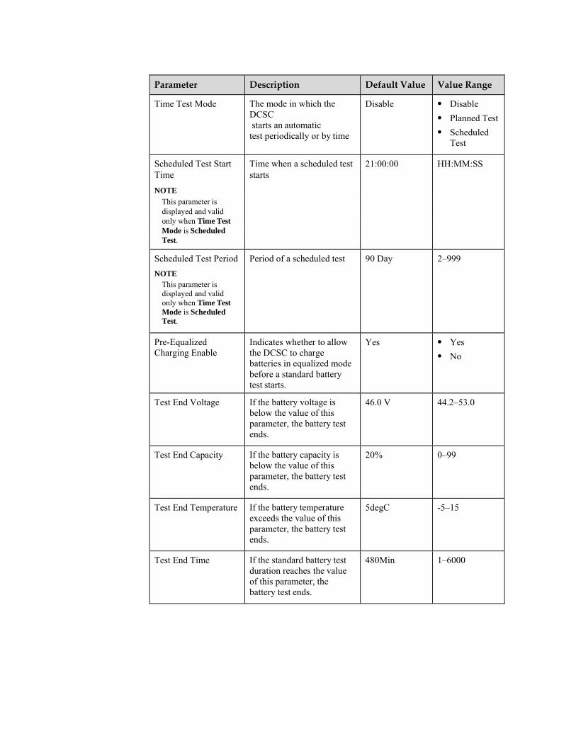
Time Test Mode The mode in which the DCSC starts an automatic test periodically or by time
Disable Disable
Planned Test
Scheduled Test
Scheduled Test Start Time when a scheduled test 21:00:00 HH:MM:SS Time starts
NOTE This parameter is displayed and valid only when Time Test Mode is Scheduled Test.
Scheduled Test Period
NOTE This parameter is displayed and valid only when Time Test Mode is Scheduled Test.
Period of a scheduled test 90 Day 2–999
Pre-Equalized Charging Enable
Indicates whether to allow the DCSC to charge batteries in equalized mode before a standard battery test starts.
Yes Yes No
Test End Voltage If the battery voltage is below the value of this parameter, the battery test ends.
46.0 V 44.2–53.0
Test End Capacity If the battery capacity is below the value of this parameter, the battery test ends.
20% 0–99
Test End Temperature If the battery temperature exceeds the value of this parameter, the battery test ends.
5degC -5–15
Test End Time If the standard battery test duration reaches the value of this parameter, the battery test ends.
480Min 1–6000

Table 8-10 Battery test report parameter description
Parameter Description
Start Time Time when a battery test starts
End Time Time when a battery test ends
Test Type Type of a battery test
Stop Reason Reason why a battery test ends
Test Result Result of a battery test
End Voltage (V) Charge voltage when a battery test ends
Average Discharge Current (A) Average discharge current during a battery test
Discharge Capacity (Ah) Amount of electricity discharged during a battery test
Battery Temperature (degC) Battery temperature when a battery test ends
LCD Operation
Set standard battery test parameters on the LCD by navigating through Parameters Settings > Battery > Standard Test Para.
Set manually start or terminate a standard battery test on the LCD by navigating through Parameters Settings > Battery > Standard Test Para. > Time Test Mode
Query standard battery test results on the LCD by navigating through Running Information > Battery > Battery Test Records
WebUI Operation
The following figure shows how to set standard battery test parameters:

Figure 8-14 Setting standard battery test parameters
The following figure shows how to manually start or terminate a standard battery test:
Figure 8-15 Manually starting or terminating a standard battery test
The following figure shows how to query standard battery test results:
Figure 8-16 Exporting standard battery test results
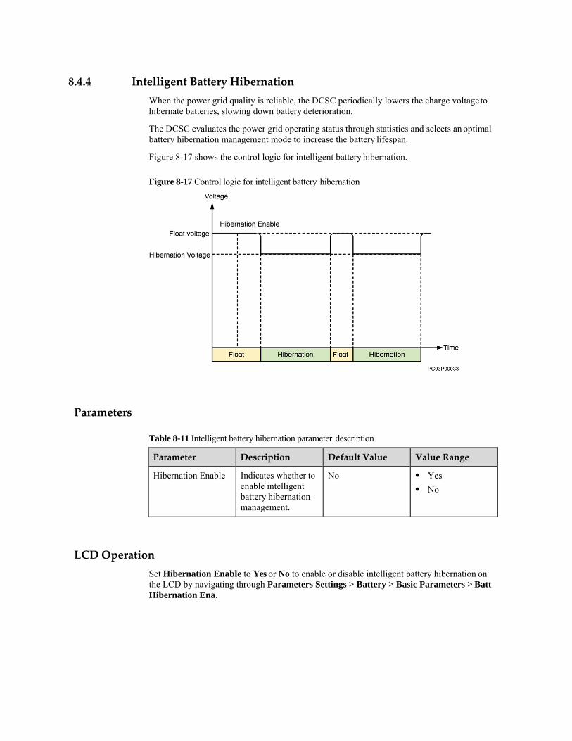
8.4.4 Intelligent Battery Hibernation
When the power grid quality is reliable, the DCSC periodically lowers the charge voltage to hibernate batteries, slowing down battery deterioration.
The DCSC evaluates the power grid operating status through statistics and selects an optimal battery hibernation management mode to increase the battery lifespan.
Figure 8-17 shows the control logic for intelligent battery hibernation.
Figure 8-17 Control logic for intelligent battery hibernation
Parameters
Table 8-11 Intelligent battery hibernation parameter description
Parameter Description Default Value Value Range
Hibernation Enable Indicates whether to enable intelligent battery hibernation management.
No Yes No
LCD Operation
Set Hibernation Enable to Yes or No to enable or disable intelligent battery hibernation on the LCD by navigating through Parameters Settings > Battery > Basic Parameters > Batt Hibernation Ena.

WebUI Operation
Figure 8-18 Setting intelligent battery hibernation
8.5 Programmable Logic Controller
The DCSC performs the flexible Programmable Logic Controller (PLC) function.
You can select any signals (such as those indicating DC undervoltage and AC power failures) and perform logical operations on them, namely, AND, OR, NOT, >, and <, and then send calculation results to dry contacts. Figure 8-19 shows the PLC conceptual diagram.
Figure 8-19 PLC conceptual diagram
The circled numbers in Figure 8-19 indicate the numbers of logic program lines, which correspond to the logic program lines in Configuration Examples.
Parameters
The following are the inputs, operators, and outputs for PLC logic programs:
.

Input:
− Signals collected by the DCSC, such as total load current signals
− Alarms generated by the DCSC, such as rectifier fault and battery high temperature alarms
− Constant
− Register: combines multiple levels of logic program lines.
Operator:
− AND: The output is active if both inputs are active.
− OR: The output is active if either input is active.
− NOT: The output is the inverse value of the input signal or constant.
− >: The output is active if the input is greater than the constant.
− <: The output is active if the input is less than the constant.
Output
− Outputs are associated with dry contact outputs and can be used for generating alarms or controlling devices.
− Register: combines multiple levels of logic program lines.
− Alarm customization: The calculation results are generated as a new alarm.
The new alarm is displayed under Power System in the alarm list. You can set the alarm name, severity, and associated dry contact.
WebUI Operation
The PLC configuration is concise and easy to operate and has the following functions:
Configures and displays PLC logic program lines.
Enables or disables each or all logic programs.
Imports or exports configuration files.
Figure 8-20 shows the PLC WebUI.
Basic Parameters: Logic program configuration is valid only when PLC Function Enable is set to Yes.
Logic List: Allows you to configure logic program lines. Figure 8-21 shows the Logic List page.
Import and Export: Allows you to import or export configuration files to generate logic program lines in batches.

Figure 8-20 PLC on the WebUI
Figure 8-21 Logic list on the WebUI
Configuration Examples
The following describes how to compile a logic program whose inputs are AC Failure or Rectifier Missing, Battery High Temperature, and Total Load Current > 30 A and whose output is an alarm signal. Figure 8-19 shows the PLC logic conceptual diagram.
To compile the logic program, perform the following steps:
Step 1 Set PLC Function Enable to Yes and click Submit.
Step 2 Compile a logic program whose inputs are AC Failure, Low Battery Capacity, and Total Load Current > 30 A and whose output is an alarm signal.
1. Add a logic program.

Figure 8-22 Adding a logic program on the WebUI
2. Compile the first logic program line whose inputs are AC Failure and Rectifier Missing,
operator is OR, and output is Register1, and click Submit.
Figure 8-23 Compiling the first logic program line on the WebUI
3. Compile the second logic program line whose inputs are Register1 and Battery High
Temperature, operator is AND, and output is Register2, and click Submit.

Figure 8-24 Compiling the second logic program line on the WebUI
4. Compile the third logic program line whose inputs are Total Load Current and 30.0, operator is >, hysteresis is 2.0, and output is Register3, and click Submit.
Figure 8-25 Compiling the third logic program line on the WebUI
5. Compile the fourth logic program line whose inputs are Register2 and Register3,
operator is AND, and output is ALM1, and click Submit.

Figure 8-26 Compiling the fourth logic program line on the WebUI
Step 3 Activate the program lines one by one that you submit on the logic list. After a program line is
activated, a green icon is displayed in the Status column.
Figure 8-27 Logic program lines activated on the WebUI
Step 4 Click Export to export the configuration file that contains the logic program lines.

Figure 8-28 Exporting a configuration file on the WebUI
8.6 Performance Statistics
Context
The DCSC collects data about AC, batteries, and power consumption in real time. You can periodically query the operating status of the power system, such as the total number of AC power failures in the current month and the total number of battery string discharge times in the current week.
AC statistics
Table 8-12 lists the AC statistics.
Table 8-12 AC statistics
Item Unit Period
AC Failure Duration h Day/Week/Month/Year
AC Failure Times N/A Day/Week/Month/Year
Maximum AC Failure Duration h Day/Week/Month/Year
Maximum AC Phase Voltage V Day/Week/Month/Year
Minimum AC Phase Voltage V Day/Week/Month/Year
Battery statistics
Table 8-13 lists the battery statistics.
Table 8-13 Battery statistics
Item Unit Period
Discharge Capacity V Day/Week/Month/Year
Total Battery Current A 5min

Item Unit Period
Remaining Capacity Percent % 5min
High Temperature Runtime h Day/Week/Month/Year
Equalized Charge Duration h Day/Week/Month/Year
Float Charge Duration h Day/Week/Month/Year
Discharge Duration h Day/Week/Month/Year
Hibernation Duration h Day/Week/Month/Year
Charge Times N/A Day/Week/Month/Year
Discharge Times N/A Day/Week/Month/Year
Maximum Charge Duration h Day/Week/Month/Year
Maximum Discharge Duration h Day/Week/Month/Year
Discharge Duration Less than 30 Min
h Day/Week/Month/Year
Discharge Duration 30 to 60 Min h Day/Week/Month/Year
Discharge Duration 60 to 120 Min h Day/Week/Month/Year
Discharge Duration 120 to 240 Min
h Day/Week/Month/Year
Discharge Duration 240 to 480 Min
h Day/Week/Month/Year
Discharge Duration More than 480 Min
h Day/Week/Month/Year
Discharge Times Less than 30 Min N/A Day/Week/Month/Year
Discharge Times of 30 to 60 Min N/A Day/Week/Month/Year
Discharge Times of 60 to 120 Min N/A Day/Week/Month/Year
Discharge Times of 120 to 240 Min
N/A Day/Week/Month/Year
Discharge Times of 240 to 480 Min
N/A Day/Week/Month/Year
Discharge Times More than 480 Min
N/A Day/Week/Month/Year
Discharge Capacity Less than 30 Min
kWh Day/Week/Month/Year
Discharge Capacity of 30 to 60 Min
kWh Day/Week/Month/Year
Discharge Capacity of 60 to 120 Min
kWh Day/Week/Month/Year

Item Unit Period
Discharge Capacity of 120 to 240 Min
kWh Day/Week/Month/Year
Discharge Capacity of 240 to 480 Min
kWh Day/Week/Month/Year
Discharge Capacity More than 480 Min
kWh Day/Week/Month/Year
Power consumption statistics
The DCSC collects power consumption data and the peak data of various key counters, as listed in Table 8-14 and Table 8-15.
Table 8-14 Traffic statistics
Item Unit Period
DC Load Power Consumption kWh H/Day/Week/Month/Year
Mains Power Consumption kWh H/Day/Week/Month/Year
Discharge Capacity kWh H/Day/Week/Month/Year
Table 8-15 Peak power consumption statistics
Item Unit Period
Maximum DC Load Power kW Day/Week/Month/Year
Minimum DC Load Power kW Day/Week/Month/Year
Querying Performance Statistics
This section describes how to query the total battery string discharge capacity in the current month. Perform the following steps:
Step 1 In the Performance Data page shown in Figure 8-29, set query conditions.
1. Set Equipment to Battery Group.
2. Set Performance Data to Discharge Capacity.
3. Set Statistical Period to Month.
4. Set the query period.

Figure 8-29 Performance data page on the WebUI
Step 2 Click Query. Qualified data records are displayed, as shown in Figure 8-30.
Figure 8-30 Performance statistics query results on the WebUI
Exporting Performance Statistics
To export performance statistics, perform the following steps:
Step 1 In the Export Data page shown in Figure 8-31, select Performance Data and click Export.
Figure 8-31 Export performance data on the WebUI
Step 2 In the display dialog box, click Save to download the performance data package to your local computer.

A LCD Menu Hierarchy
The menu hierarchy and parameter display depend on the system type, parameter settings, and device connections. LCD Menu Hierarchy may be different due to different software versions or updates.
Table A-1 Active alarm menu hierarchy
Second‐Level Menu Third‐Level Menu Fourth‐Level Menu
Active Alarm - -
Table A-2 Running information menu hierarchy
Second‐Level Menu Third‐Level Menu Fourth‐Level Menu
Power System Basic Information System Voltage
Total Load Current
AC Voltage
AC Current
Ambient Temperature
DO Control Status ALM1 Control Status
ALM2 Control Status
ALM3 Control Status
ALM4 Control Status
ALM5 Control Status
ALM6 Control Status
ALM7 Control Status
ALM8 Control Status
Rectifier Rectifier Group Total Current

Second‐Level Menu Third‐Level Menu Fourth‐Level Menu
Total DC Power
Load Usage
Rectifier n Slot No.
DC Output Voltage
AC Voltage
Rectifier Temp.
Cur. Limiting Status
Run Status
Hardware Version
Software Version
Bar Code
Battery Battery Group Battery Status
Total Batt. Current
Remain Cap. Percent
Cur. Limiting Status
Test Status
Battery Temp.
Battery String n Current
Remain Cap. Percent
Battery Test Records -
Historical Alarm - -
Table A-3 Setting wizard menu hierarchy
Second‐Level Menu
Third‐Level Menu
Fourth‐Level Menu
Fifth‐Level Menu
Default Value Value Range
Battery Parameters
Battery1 Connected
- - Yes Yes, No
Rated Capacity - - 150 Ah 5–10000
Date and Time Date and Time - - - -
Time Zone - - UTC -06:00 Central America
Time zones of all the major cities in the

Second‐Level Menu
Third‐Level Menu
Fourth‐Level Menu
Fifth‐Level Menu
Default Value Value Range
world. For details, see the WebUI.
NTP Enable - - No Yes, No
Network Parameters
IP Address - - 192.168.0.10 -
Subnet Mask - - 255.255.255.0 -
Default Gateway
- - 192.168.0.1 -
Table A-4 Parameters settings menu hierarchy
Second‐Level Menu
Third‐Level Menu
Fourth‐Level Menu
Fifth‐Level Menu
Default Value
Value Range
Power System Basic Parameters
LLVD Enable - None Present, None
Buzzer Enable - No Yes, No
LLVD Parameters
LLVD Enable - Present Present, None
LLVD Open Voltage
- 45.0 V 35.0-56.0
LLVD Close Voltage
- 51.5 V 37.0-58.0
LLVD Delay Time
- 60 s 5-90
Alm Threshold Para.
DC OV Thres. - 58.0 V 53.0-60.0
DC UV Thres. - 45.0 V 35.0-57.0
DC Ultra UV Thres.
- 44.0 V 35.0-57.0
Amb. HT Thres. - 55 degC 25-80
Amb. LT Thres. - -20 degC -20-20
Rectifier Rect. Hibernation En
- - No Yes, No
Hibernation Mode
NOTE
This parameter is valid when Hibernation enable is set to Yes
- - Intelligent Mode
High Mode, High Efficiency Mode, Time Mode

Min Workin Rects.
NOTE
This parameter is valid when Hibernation enable is set to Yes
- - 2 1-100
Circulation Period
NOTE
This parameter is valid when Hibernation enable is set to Yes
- - 7 Day 1-365
Best Efficiency Pt.
NOTE
This parameter is valid when Hibernation enable is set to Yes
- - 80% 50-100
Min. Rdnt. Coef.
NOTE
This parameter is valid when Hibernation enable is set to Yes
- - 0.20 0.05-1.00
Phase Balance
NOTE
This parameter is valid when Hibernation enable is set to Yes
- - Disable Relative Balance, Absolute Balance, Disable

Hiber. Without Batt.
NOTE
This parameter is valid when Hibernation enable is set to Yes
- - No Yes, No
Hiber. Stop Duration
NOTE
This parameter is valid when Hibernation enable is set to Yes
- - 72.0 h 0.5-168.0
Sequential St. Int.
- - 0 s 0-20
WALK-IN Enable
- - No Yes, No
Battery Basic Parameters
Battery1 Connected
- Yes Yes, No
Battery Basic Parameters
Battery2 Connected
- Yes Yes, No

Second‐Level Menu
Third‐Level Menu
Fourth‐Level Menu
Fifth‐Level Menu
Default Value
Value Range
Rated Capacity - 100 Ah 5-10000
FC Voltage - 54.0 V 42.0-58.3
EC Voltage - 55.0 V 42.0-58.3
Charge Limit Enable
- Yes Yes, No
Charge Limit Coef.
- 0.15C10 0.05-0.25
BLVD Enable - Yes Yes, No
Batt Hibernation Ena
- No Yes, No
TC Coefficient - 80 mV/degC 0-500
Nominal Temperature
- 25 degC 5-45
TC Upper Thres.
- 45 degC 40-45
TC Lower Thres.
- 5 degC 5-10
BLVD Parameters
BLVD Enable - Yes Yes, No
BLVD Open Voltage
- 43.2 V 35.0-56.0
BLVD Close Voltage
- 51.5 V 37.0-58.0
BLVD Delay Time
- 60s 5-90
Temp. Parameters
Batt HT Thres. - 50 degC 25-80
Batt LT Thres. - -10 degC -20-20
Charge Parameters
Auto. EC Enable
- No Yes, No
FC-EC Cur. Coef.
- 0.05 C10 0.01-0.25
FC-EC Cur. Duration
- 30 Min 2-1440
FC-EC Cap. Percent
- 80% 50-100
Sche. EC Enable
- No Yes, No

Second‐Level Menu
Third‐Level Menu
Fourth‐Level Menu
Fifth‐Level Menu
Default Value
Value Range
Sche. EC Interval
- 30 Day 1-365
EC-FC Cur. Coef.
- 0.01 C10 0.01-0.25
EC-FC Cur. Duration
- 30 Min 2-540
Sche. EC Duration
- 9 h 1-24
EC Max Duration
- 16 h 5-48
Mains Recovery EC En
- No Yes, No
Fast Charge Coef.
- 0.40 C10 0.25-0.50
Standard Test Para.
Test Bat. Dur. AC Fa
- No Yes, No
Time Test Mode - Disable Disable, Scheduled Test, Planned Test
Pre-EC Enable - No Yes, No
Constant Cur. Test
- No Yes, No
Test End Voltage
- 46.0 V 44.2-53.0
Test End Capacity
- 20% 0-99
Test End Time - 480 Min 1-6000
Test End Temperature
- 5 degC -5-15
Alarm Parameters
DI Dry Contact Para.
DIN1 Alm. Cond.
- Close Close, Open
(12V)
DIN2 Alm. Cond.
- Close Close, Open
(12V)
DIN3 Alm. Cond.
- Close Close, Open
(12V)
DIN4 Alm. Cond.
- Close Close, Open
(12V)
DIN5 Alm. Cond.
- Close Close, Open
(12V)

Second‐Level Menu
Third‐Level Menu
Fourth‐Level Menu
Fifth‐Level Menu
Default Value
Value Range
DIN6 Alm. Cond.
- Close Close, Open
(12V)
DO Dry Contact Para.
ALM1 Alarm Action
- Close Close, Open
ALM2 Alarm Action
- Close Close, Open
ALM3 Alarm Action
- Close Close, Open
ALM4 Alarm Action
- Close Close, Open
ALM5 Alarm Action
- Close Close, Open
ALM6 Alarm Action
- Close Close, Open
ALM7 Alarm Action
- Close Close, Open
ALM8 Alarm Action
- Close Close, Open
Alarm Parameters
Power System - - -
Rectifier - - -
Rectifier Group - - -
Battery Group - - -
Battery String - - -
Alarm Level DO Para.
Cri. Alm. Asso. DO
- No ALM1–ALM8
Major Alm. Asso. DO
- No ALM1–ALM8
Minor Alm. Asso. DO
- No ALM1–ALM8
Warn. Alm. Asso. DO
- No ALM1–ALM8
Clear ALM Asso.
Clear ALM1 Asso.
- Yes Yes
Clear ALM2 Asso.
- Yes Yes
Clear ALM3 Asso.
- Yes Yes

Second‐Level Menu
Third‐Level Menu
Fourth‐Level Menu
Fifth‐Level Menu
Default Value
Value Range
Clear ALM4 Asso.
- Yes Yes
Clear ALM5 Asso.
- Yes Yes
Clear ALM6 Asso.
- Yes Yes
Clear ALM7 Asso.
- Yes Yes
Clear ALM8 Asso.
- Yes Yes
Clear ALM9 Asso.
- Yes Yes
Network Parameters
IP Address - - 192.168.0.10 -
Subnet Mask - - 255.255.255.0 -
Default Gateway
- - 192.168.0.1 -
Local Parameters
Site ID Site ID - - -
Date and Time Date and Time
Time Zone
Ntp Enable
- - -
LCD Contrast Contrast - 5 0-10
Change Password
- - - -
Table A-5 Running control menu hierarchy
Second‐Level Menu
Third‐Level Menu
Fourth‐Level Menu
Fifth‐Level Menu
Default Value Value Range
Power System System Control Mode
- - Automatic Automatic, Manual
Reboot Controller
- - Yes Yes, No
Rectifier Rectifier Group OV Lock Reset - Yes -
Rectifier Re-configuration
- Yes -

Second‐Level Menu
Third‐Level Menu
Fourth‐Level Menu
Fifth‐Level Menu
Default Value Value Range
Rectifier n Turn on/off
NOTE This parameter is valid when System Control is set to Manual Mode.
- On On, Off
Battery Battery Test Control
- - Stop Stop, Start
Clear Alarm Historical Alarm
Delete His. Alarms
- Yes Yes
Active Alarm - - - -
Clear Batt. Test Log
Clear Test Log - - Yes Yes
Output Relay Test
Test Enable - - No No, Yes

B Alarm Description
Table B-1 Power system alarm settings
Alarm Alarm Properties
LCD WebUI Alarm Enabled Alarm Severity Relay
AC Failure AC Failure Enable Major No
DC OV DC Overvoltage Enable Minor No
DC Ultra UV DC Ultra Overvoltage
Disable Critical No
DC UV DC Undervoltage Enable Major No
Load Fuse/ Breaker Fa
Load Fuse/Breaker Failure
Enable Major No
DCSC Fault DCSC Enable Major No
Insuff. Alm Space Insufficient Alarm Space
Disable Warning No
High Amb. Temp. High Ambient Temperature
Enable Minor No
Low Amb. Temp. Low Ambient Temperature
Enable Warning No
Amb. TS Missing Ambient Temperature Sensor Missing
Enable Warning No
Amb. TS Fault Ambient Temperature Sensor Fault
Enable Major No
LLVD Open LLVD Open Enable Major No
DIN1 Alarm DIN1 Alarm Enable Minor No
DIN2 Alarm DIN2 Alarm Enable Minor No
DIN3 Alarm DIN3 Alarm Enable Minor No

Alarm Alarm Properties
LCD WebUI Alarm Enabled Alarm Severity Relay
DIN4 Alarm DIN4 Alarm Enable Minor No
DIN5 Alarm DIN5 Alarm Enable Minor No
DIN6 Alarm DIN6 Alarm Enable Minor No
Abn Sys. Volt. Check
Abnormal System Voltage Check
Disable Major No
Abn Sys. Cur. Check
Abnormal System Current Check
Disable Major No
Table B-2 Rectifier alarm settings
Alarm Alarm Properties
LCD WebUI Alarm Enabled Alarm Severity Relay
Rectifier Fault Rectifier Fault Enable Major No
Rect. Comm. Failure
Rectifier Communication Failure
Enable Minor No
Table B-3 Rectifier group alarm settings
Alarm Alarm Properties
LCD WebUI Alarm Enabled Alarm Severity Relay
Rectifier Missing Rectifier Missing Enable Major No
Multi-Rect. Fault Multi-Rectifier Fault Enable Major No
Low Rect. Capacity Low Rectifier Capacity
Enable Critical No
Table B-4 Battery group alarm settings
Alarm Alarm Properties
LCD WebUI Alarm Enabled Alarm Severity Relay
Batt. High Temp. Battery High Temperature
Enable Minor No
Batt. Low Temp. Battery Low Temperature
Enable Warning No

Alarm Alarm Properties
LCD WebUI Alarm Enabled Alarm Severity Relay
Batt. TS Fault Battery Temperature Sensor Fault
Enable Major No
BLVD Open BLVD Open Enable Major No
Batt. Reversely Con.
Battery Reversely Connection
Enable Major No
Batt. Chg. Overcur. Battery Charge Overcurrent
Enable Major No
Batt. Ec Prot. Battery Charge Overcurrent
Enable Major No
Table B-5 Battery string alarm settings
Alarm Alarm Properties
LCD WebUI Alarm Enabled Alarm Severity Relay
Batt. Fuse/ Breaker Fa
Battery Fuse/ Breaker Failure
Enable Critical No