dd200 restorer user guide - dell emc · disclaimer the information contained in this publication is...
TRANSCRIPT

DD200 Restorer
User Guide
Disclaimer
The information contained in this publication is subject to change without notice. Data Domain, Incorporated makes no warranty of any kind with regard to this manual, including, but not limited to, the implied warranties of merchantability and fitness for a particular purpose. Data Domain, Incorporated shall not be liable for errors contained herein or for incidental or consequential damages in connection with the furnishing, performance, or use of this manual.
Notices
NOTE: Data Domain hardware has been tested and found to comply with the limits for a Class A digital device, pursuant to Part 15 of the FCC Rules. These limits are designed to provide reasonable protection against harmful interference when the equipment is operated in a commercial environment. This equipment generates, uses, and can radiate radio frequency energy and, if not installed and used in accordance with the instruction manual, may cause harmful interference to radio communications. Operation of this equipment in a residential area is likely to cause harmful interference in which case the user will be required to correct the interference at his own expense.
Changes or modifications not expressly approved by Data Domain can void the user's authority to operate the equipment.
Copyright
Copyright © 2004 Data Domain, Incorporated. All rights reserved. Data Domain, the Data Domain logo, DD200 Restorer, Global Compression, Data Invulnerability Architecture, and all other Data Domain product names and slogans are trademarks or registered trademarks of Data Domain, Incorporated in the USA and/or other countries. Microsoft and Windows are either registered trademarks or trademarks of Microsoft Corporation in the United States and/or other countries. Portions of this product are software covered by the GNU General Public License Copyright © 1989, 1991 by Free Software Foundation, Inc. Portions of this product are software covered by the GNU Lesser General Public License Copyright © 1991, 1999 by Free Software Foundation, Inc. Portions of this product are software covered by the GNU Free Documentation License Copyright © 2000, 2001, 2002, by Free Software Foundation, Inc. Portions of this product are software Copyright © 1999 - 2003, by The OpenLDAP Foundation. Portions of this product are software developed by the OpenSSL Project for use in the OpenSSL Toolkit (http://www.openssl.org/), Copyright © 1998-2004 The OpenSSL Project, all rights reserved. Portions of this product are Berkeley Software Distribution software, Copyright © 1988 - 2004 by the Regents of the University of California, University of California, Berkeley. Portions of this product are software Copyright © 1990 - 1999 by Sleepycat Software. Portions of this product are software Copyright © 1985-2004 by the Massachusetts Institute of Technology. All rights reserved. Portions of this product are LILO program code, Copyright © 1992 - 1998 Werner Almesberger. All rights reserved. Portions of this product are software Copyright © 1999 - 2004 The Apache Software Foundation, licensed under the Apache License, Version 2.0 (http://www.apache.org/licenses /LICENSE-2.0). Portions of this product are derived from software Copyright © 1994, 1995, 1996, 1997, 1998, 1999, 2000, 2001, 2002 by Cold Spring Harbor Laboratory. Funded under Grant P41-RR02188 by the National Institutes of Health. Portions of this product are derived from software Copyright © 1996, 1997, 1998, 1999, 2000, 2001, 2002 by Boutell.Com, Inc. Portions of
this product relating to GD2 format are derived from software Copyright © 1999, 2000, 2001, 2002 Philip Warner. Portions of this product relating to PNG are derived from software Copyright © 1999, 2000, 2001, 2002 Greg Roelofs. Portions of this product relating to gdttf.c are derived from software Copyright © 1999, 2000, 2001, 2002 John Ellson ([email protected]). Portions of this product relating to gdft.c are derived from software Copyright © 2001, 2002 John Ellson ([email protected]). Portions of this product relating to JPEG and to color quantization are derived from software Copyright © 2000,2001, 2002, Doug Becker and copyright (C) 1994, 1995, 1996, 1997, 1998, 1999, 2000, 2001, 2002, Thomas G. Lane. This software is based in part on the work of the Independent JPEG Group. Portions of this product relating to WBMP are derived from software Copyright © 2000, 2001, 2002 Maurice Szmurlo and Johan Van den Brande. Other product names and/or slogans mentioned herein may be trademarks or registered trademarks of their respective companies.
Data Domain, Incorporated 3400 Hillview Ave. Bldg.3, 2nd Floor Palo Alto, CA 94304 USA Phone 650–565-7300 Fax 650–424-1057 www.datadomain.com
Restore Protection Manager 2.0.5.0
March 4, 2005
Part number: 760-0200-0500

Contents
About This Guide . . . . . . . . . . . . . . . . . . . . . . . . . . . . . . . . . . . . . . . . . . . . . . . . . . . . .xviiConventions . . . . . . . . . . . . . . . . . . . . . . . . . . . . . . . . . . . . . . . . . . . . . . . . . . . . . . . . . . . . . xviii
Audience . . . . . . . . . . . . . . . . . . . . . . . . . . . . . . . . . . . . . . . . . . . . . . . . . . . . . . . . . . . . . . . . . xix
Contacting Data Domain . . . . . . . . . . . . . . . . . . . . . . . . . . . . . . . . . . . . . . . . . . . . . . . . . . . . . xix
Chapter 1: Introduction . . . . . . . . . . . . . . . . . . . . . . . . . . . . . . . . . . . . . . . . . . . . . . . . .1
Applications that Send Data to a Restorer . . . . . . . . . . . . . . . . . . . . . . . . . . . . . . . . . . . . . . . . . 2
Data Integrity . . . . . . . . . . . . . . . . . . . . . . . . . . . . . . . . . . . . . . . . . . . . . . . . . . . . . . . . . . . . . . . 2
Data Compression . . . . . . . . . . . . . . . . . . . . . . . . . . . . . . . . . . . . . . . . . . . . . . . . . . . . . . . . . . . . 3
Restore Operations . . . . . . . . . . . . . . . . . . . . . . . . . . . . . . . . . . . . . . . . . . . . . . . . . . . . . . . . . . . 3
Licensing . . . . . . . . . . . . . . . . . . . . . . . . . . . . . . . . . . . . . . . . . . . . . . . . . . . . . . . . . . . . . . . . . . . 4
Restorer Interfaces . . . . . . . . . . . . . . . . . . . . . . . . . . . . . . . . . . . . . . . . . . . . . . . . . . . . . . . . . . . 4
Related Documentation . . . . . . . . . . . . . . . . . . . . . . . . . . . . . . . . . . . . . . . . . . . . . . . . . . . . . . . . 5
Initial System Settings . . . . . . . . . . . . . . . . . . . . . . . . . . . . . . . . . . . . . . . . . . . . . . . . . . . . . . . . 5
Command Line Interface . . . . . . . . . . . . . . . . . . . . . . . . . . . . . . . . . . . . . . . . . . . . . . . . . . . . . . 6
Chapter 2: Disk Space Management . . . . . . . . . . . . . . . . . . . . . . . . . . . . . . . . . . . . . . .9
Space Management . . . . . . . . . . . . . . . . . . . . . . . . . . . . . . . . . . . . . . . . . . . . . . . . . . . . . . . . . . . 9
Estimate Use of Disk Space . . . . . . . . . . . . . . . . . . . . . . . . . . . . . . . . . . . . . . . . . . . . . . . . . . . 10
Reclaim Data Storage Disk Space . . . . . . . . . . . . . . . . . . . . . . . . . . . . . . . . . . . . . . . . . . . . . . 11
Manage File System Use of Disk Space . . . . . . . . . . . . . . . . . . . . . . . . . . . . . . . . . . . . . . . . . . 12
Display the Space Usage Graph . . . . . . . . . . . . . . . . . . . . . . . . . . . . . . . . . . . . . . . . . . . . . . . . 13
v
Chapter 3: Installation . . . . . . . . . . . . . . . . . . . . . . . . . . . . . . . . . . . . . . . . . . . . . . . . 15
Site Requirements . . . . . . . . . . . . . . . . . . . . . . . . . . . . . . . . . . . . . . . . . . . . . . . . . . . . . . . . . . 16
Backup Software Requirements . . . . . . . . . . . . . . . . . . . . . . . . . . . . . . . . . . . . . . . . . . . . . . . . 17
CIFS Backup Server Timeout . . . . . . . . . . . . . . . . . . . . . . . . . . . . . . . . . . . . . . . . . . . . . . . . . 17
DHCP Server . . . . . . . . . . . . . . . . . . . . . . . . . . . . . . . . . . . . . . . . . . . . . . . . . . . . . . . . . . . . . . 17
Hardware Installation . . . . . . . . . . . . . . . . . . . . . . . . . . . . . . . . . . . . . . . . . . . . . . . . . . . . . . . . 18
Login and Configuration . . . . . . . . . . . . . . . . . . . . . . . . . . . . . . . . . . . . . . . . . . . . . . . . . . . . . 20
Additional Configuration . . . . . . . . . . . . . . . . . . . . . . . . . . . . . . . . . . . . . . . . . . . . . . . . . . . . . 29
Administering a Restorer . . . . . . . . . . . . . . . . . . . . . . . . . . . . . . . . . . . . . . . . . . . . . . . . . . . . . 30
Chapter 4: Configuration Management . . . . . . . . . . . . . . . . . . . . . . . . . . . . . . . . . . . 31
The Config Command . . . . . . . . . . . . . . . . . . . . . . . . . . . . . . . . . . . . . . . . . . . . . . . . . . . . . . . 31
Change Configuration Settings . . . . . . . . . . . . . . . . . . . . . . . . . . . . . . . . . . . . . . . . . . . . . 31
Display Configuration Keys and Settings . . . . . . . . . . . . . . . . . . . . . . . . . . . . . . . . . . . . . 32
Display a Single Configuration Setting . . . . . . . . . . . . . . . . . . . . . . . . . . . . . . . . . . . . . . . 32
Return to the Default Configuration . . . . . . . . . . . . . . . . . . . . . . . . . . . . . . . . . . . . . . . . . . 33
Save and Return a Configuration . . . . . . . . . . . . . . . . . . . . . . . . . . . . . . . . . . . . . . . . . . . . 34
The License Command . . . . . . . . . . . . . . . . . . . . . . . . . . . . . . . . . . . . . . . . . . . . . . . . . . . . . . 34
Add a License . . . . . . . . . . . . . . . . . . . . . . . . . . . . . . . . . . . . . . . . . . . . . . . . . . . . . . . . . . . 34
Remove a License . . . . . . . . . . . . . . . . . . . . . . . . . . . . . . . . . . . . . . . . . . . . . . . . . . . . . . . 35
Reset Licenses . . . . . . . . . . . . . . . . . . . . . . . . . . . . . . . . . . . . . . . . . . . . . . . . . . . . . . . . . . 35
Display Licenses . . . . . . . . . . . . . . . . . . . . . . . . . . . . . . . . . . . . . . . . . . . . . . . . . . . . . . . . . 35
Chapter 5: Access Control for Administration . . . . . . . . . . . . . . . . . . . . . . . . . . . . . 37
Add a Host . . . . . . . . . . . . . . . . . . . . . . . . . . . . . . . . . . . . . . . . . . . . . . . . . . . . . . . . . . . . . . . . 37
Remove a Host . . . . . . . . . . . . . . . . . . . . . . . . . . . . . . . . . . . . . . . . . . . . . . . . . . . . . . . . . . . . . 37
Reset a List . . . . . . . . . . . . . . . . . . . . . . . . . . . . . . . . . . . . . . . . . . . . . . . . . . . . . . . . . . . . . . . . 38
Enable a Protocol . . . . . . . . . . . . . . . . . . . . . . . . . . . . . . . . . . . . . . . . . . . . . . . . . . . . . . . . . . . 38
Disable a Protocol . . . . . . . . . . . . . . . . . . . . . . . . . . . . . . . . . . . . . . . . . . . . . . . . . . . . . . . . . . 38
Add an Authorized SSH Public Key . . . . . . . . . . . . . . . . . . . . . . . . . . . . . . . . . . . . . . . . . . . . 38
Remove an SSH Key File Entry . . . . . . . . . . . . . . . . . . . . . . . . . . . . . . . . . . . . . . . . . . . . . . . 39
vi DD200 Restorer User Guide
Remove the SSH Key File . . . . . . . . . . . . . . . . . . . . . . . . . . . . . . . . . . . . . . . . . . . . . . . . . . . . 39
Display the SSH Key File . . . . . . . . . . . . . . . . . . . . . . . . . . . . . . . . . . . . . . . . . . . . . . . . . . . . . 39
Display Hosts and Status . . . . . . . . . . . . . . . . . . . . . . . . . . . . . . . . . . . . . . . . . . . . . . . . . . . . . 40
Return Command Output to a Remote machine . . . . . . . . . . . . . . . . . . . . . . . . . . . . . . . . . . . . 40
Chapter 6: User Administration . . . . . . . . . . . . . . . . . . . . . . . . . . . . . . . . . . . . . . . . .41
Add a User . . . . . . . . . . . . . . . . . . . . . . . . . . . . . . . . . . . . . . . . . . . . . . . . . . . . . . . . . . . . . . . . 41
Remove a User . . . . . . . . . . . . . . . . . . . . . . . . . . . . . . . . . . . . . . . . . . . . . . . . . . . . . . . . . . . . . 41
Change a Password . . . . . . . . . . . . . . . . . . . . . . . . . . . . . . . . . . . . . . . . . . . . . . . . . . . . . . . . . . 42
Reset to the Default User . . . . . . . . . . . . . . . . . . . . . . . . . . . . . . . . . . . . . . . . . . . . . . . . . . . . . 42
Display Current Users . . . . . . . . . . . . . . . . . . . . . . . . . . . . . . . . . . . . . . . . . . . . . . . . . . . . . . . . 42
Display All Users . . . . . . . . . . . . . . . . . . . . . . . . . . . . . . . . . . . . . . . . . . . . . . . . . . . . . . . . . . . 43
Chapter 7: Alerts and System Reports . . . . . . . . . . . . . . . . . . . . . . . . . . . . . . . . . . . .45
Alerts . . . . . . . . . . . . . . . . . . . . . . . . . . . . . . . . . . . . . . . . . . . . . . . . . . . . . . . . . . . . . . . . . . . . . 46
Add to the Email List . . . . . . . . . . . . . . . . . . . . . . . . . . . . . . . . . . . . . . . . . . . . . . . . . . . . . 46
Test the Email List . . . . . . . . . . . . . . . . . . . . . . . . . . . . . . . . . . . . . . . . . . . . . . . . . . . . . . . 46
Remove from the Email List . . . . . . . . . . . . . . . . . . . . . . . . . . . . . . . . . . . . . . . . . . . . . . . . 46
Reset the Email List . . . . . . . . . . . . . . . . . . . . . . . . . . . . . . . . . . . . . . . . . . . . . . . . . . . . . . 47
Display Current Alerts . . . . . . . . . . . . . . . . . . . . . . . . . . . . . . . . . . . . . . . . . . . . . . . . . . . . 47
Display the Email List . . . . . . . . . . . . . . . . . . . . . . . . . . . . . . . . . . . . . . . . . . . . . . . . . . . . . 47
Display the Alerts History . . . . . . . . . . . . . . . . . . . . . . . . . . . . . . . . . . . . . . . . . . . . . . . . . . 48
Display Current Alerts and Recent History . . . . . . . . . . . . . . . . . . . . . . . . . . . . . . . . . . . . 48
Display the Email List and Administrator Email . . . . . . . . . . . . . . . . . . . . . . . . . . . . . . . . 49
Autosupport Reports . . . . . . . . . . . . . . . . . . . . . . . . . . . . . . . . . . . . . . . . . . . . . . . . . . . . . . . . . 49
Add to the Email List . . . . . . . . . . . . . . . . . . . . . . . . . . . . . . . . . . . . . . . . . . . . . . . . . . . . . 49
Remove from the Email List . . . . . . . . . . . . . . . . . . . . . . . . . . . . . . . . . . . . . . . . . . . . . . . . 49
Reset the Email List . . . . . . . . . . . . . . . . . . . . . . . . . . . . . . . . . . . . . . . . . . . . . . . . . . . . . . 50
Test the Autosupport Report Email List . . . . . . . . . . . . . . . . . . . . . . . . . . . . . . . . . . . . . . . 50
Set the Schedule . . . . . . . . . . . . . . . . . . . . . . . . . . . . . . . . . . . . . . . . . . . . . . . . . . . . . . . . . 50
Reset the Schedule . . . . . . . . . . . . . . . . . . . . . . . . . . . . . . . . . . . . . . . . . . . . . . . . . . . . . . . 51
Contents vii

Reset the Schedule and the List . . . . . . . . . . . . . . . . . . . . . . . . . . . . . . . . . . . . . . . . . . . . . 51
Run the Autosupport Report . . . . . . . . . . . . . . . . . . . . . . . . . . . . . . . . . . . . . . . . . . . . . . . . 51
Send Disk Debug Information . . . . . . . . . . . . . . . . . . . . . . . . . . . . . . . . . . . . . . . . . . . . . . 52
Display all Autosupport Parameters . . . . . . . . . . . . . . . . . . . . . . . . . . . . . . . . . . . . . . . . . . 52
Display the Autosupport Email List . . . . . . . . . . . . . . . . . . . . . . . . . . . . . . . . . . . . . . . . . . 53
Display the Autosupport History . . . . . . . . . . . . . . . . . . . . . . . . . . . . . . . . . . . . . . . . . . . . 53
Display the Autosupport Report Schedule . . . . . . . . . . . . . . . . . . . . . . . . . . . . . . . . . . . . . 54
Hourly System Status . . . . . . . . . . . . . . . . . . . . . . . . . . . . . . . . . . . . . . . . . . . . . . . . . . . . . . . . 54
Chapter 8: File System Management . . . . . . . . . . . . . . . . . . . . . . . . . . . . . . . . . . . . 55
Statistics and Basic Operations . . . . . . . . . . . . . . . . . . . . . . . . . . . . . . . . . . . . . . . . . . . . . . . . 55
Start the Restorer File System Process . . . . . . . . . . . . . . . . . . . . . . . . . . . . . . . . . . . . . . . . 55
Stop the Restorer File System Process . . . . . . . . . . . . . . . . . . . . . . . . . . . . . . . . . . . . . . . . 55
Delete All Data in the File System . . . . . . . . . . . . . . . . . . . . . . . . . . . . . . . . . . . . . . . . . . . 55
Display File System Status . . . . . . . . . . . . . . . . . . . . . . . . . . . . . . . . . . . . . . . . . . . . . . . . . 56
Display File System Uptime . . . . . . . . . . . . . . . . . . . . . . . . . . . . . . . . . . . . . . . . . . . . . . . . 56
Display File System Space Utilization . . . . . . . . . . . . . . . . . . . . . . . . . . . . . . . . . . . . . . . . 56
Display Compression . . . . . . . . . . . . . . . . . . . . . . . . . . . . . . . . . . . . . . . . . . . . . . . . . . . . . 58
Clean Operations . . . . . . . . . . . . . . . . . . . . . . . . . . . . . . . . . . . . . . . . . . . . . . . . . . . . . . . . . . . 59
Start Cleaning . . . . . . . . . . . . . . . . . . . . . . . . . . . . . . . . . . . . . . . . . . . . . . . . . . . . . . . . . . . 60
Stop Cleaning . . . . . . . . . . . . . . . . . . . . . . . . . . . . . . . . . . . . . . . . . . . . . . . . . . . . . . . . . . . 61
Change the Schedule . . . . . . . . . . . . . . . . . . . . . . . . . . . . . . . . . . . . . . . . . . . . . . . . . . . . . 61
Set the Schedule or Amount to the Default . . . . . . . . . . . . . . . . . . . . . . . . . . . . . . . . . . . . 62
Set the Run Time, Gigabytes, or Percent Cleaned . . . . . . . . . . . . . . . . . . . . . . . . . . . . . . . 62
Set System Resources Used . . . . . . . . . . . . . . . . . . . . . . . . . . . . . . . . . . . . . . . . . . . . . . . . 62
Update Statistics . . . . . . . . . . . . . . . . . . . . . . . . . . . . . . . . . . . . . . . . . . . . . . . . . . . . . . . . . 63
Display the Schedule . . . . . . . . . . . . . . . . . . . . . . . . . . . . . . . . . . . . . . . . . . . . . . . . . . . . . 63
Display the Amount Parameters . . . . . . . . . . . . . . . . . . . . . . . . . . . . . . . . . . . . . . . . . . . . . 63
Display the Throttle Setting . . . . . . . . . . . . . . . . . . . . . . . . . . . . . . . . . . . . . . . . . . . . . . . . 63
viii DD200 Restorer User Guide
Display the Clean Operation Status . . . . . . . . . . . . . . . . . . . . . . . . . . . . . . . . . . . . . . . . . . 64
Display Recommended Cleaning Times . . . . . . . . . . . . . . . . . . . . . . . . . . . . . . . . . . . . . . . 64
Chapter 9: Disk Management . . . . . . . . . . . . . . . . . . . . . . . . . . . . . . . . . . . . . . . . . . .65
Fail a Disk . . . . . . . . . . . . . . . . . . . . . . . . . . . . . . . . . . . . . . . . . . . . . . . . . . . . . . . . . . . . . . . . . 65
Identify a Physical Disk in the Chassis . . . . . . . . . . . . . . . . . . . . . . . . . . . . . . . . . . . . . . . . . . . 66
Check All Disks . . . . . . . . . . . . . . . . . . . . . . . . . . . . . . . . . . . . . . . . . . . . . . . . . . . . . . . . . . . . 66
Display Disk Locations . . . . . . . . . . . . . . . . . . . . . . . . . . . . . . . . . . . . . . . . . . . . . . . . . . . . . . . 66
Display Disk Type and Capacity Information . . . . . . . . . . . . . . . . . . . . . . . . . . . . . . . . . . . . . 67
Display the RAID Use of Disks . . . . . . . . . . . . . . . . . . . . . . . . . . . . . . . . . . . . . . . . . . . . . . . . 67
Display Disk Status . . . . . . . . . . . . . . . . . . . . . . . . . . . . . . . . . . . . . . . . . . . . . . . . . . . . . . . . . . 68
Display RAID Status for Disks . . . . . . . . . . . . . . . . . . . . . . . . . . . . . . . . . . . . . . . . . . . . . . . . . 69
Display Performance Details . . . . . . . . . . . . . . . . . . . . . . . . . . . . . . . . . . . . . . . . . . . . . . . . . . 70
Reset Disk Performance Statistics . . . . . . . . . . . . . . . . . . . . . . . . . . . . . . . . . . . . . . . . . . . . . . 70
Display Disk Reliability Details . . . . . . . . . . . . . . . . . . . . . . . . . . . . . . . . . . . . . . . . . . . . . . . . 71
Display Disk Debug Information . . . . . . . . . . . . . . . . . . . . . . . . . . . . . . . . . . . . . . . . . . . . . . . 72
Chapter 10: System Management . . . . . . . . . . . . . . . . . . . . . . . . . . . . . . . . . . . . . . . .73
The System Command . . . . . . . . . . . . . . . . . . . . . . . . . . . . . . . . . . . . . . . . . . . . . . . . . . . . . . . 73
Shut down the Restorer Hardware . . . . . . . . . . . . . . . . . . . . . . . . . . . . . . . . . . . . . . . . . . . 73
Reboot the Restorer . . . . . . . . . . . . . . . . . . . . . . . . . . . . . . . . . . . . . . . . . . . . . . . . . . . . . . . 73
Upgrade Restorer Software . . . . . . . . . . . . . . . . . . . . . . . . . . . . . . . . . . . . . . . . . . . . . . . . . 74
To upgrade from the Data Domain web site . . . . . . . . . . . . . . . . . . . . . . . . . . . . . . . . . 74
To upgrade from a CD . . . . . . . . . . . . . . . . . . . . . . . . . . . . . . . . . . . . . . . . . . . . . . . . . . 75
To upgrade using FTP . . . . . . . . . . . . . . . . . . . . . . . . . . . . . . . . . . . . . . . . . . . . . . . . . . 75
Change the Mail Server Hostname . . . . . . . . . . . . . . . . . . . . . . . . . . . . . . . . . . . . . . . . . . . 75
Change the Administrative Email Address . . . . . . . . . . . . . . . . . . . . . . . . . . . . . . . . . . . . . 76
Change the Administrative Host . . . . . . . . . . . . . . . . . . . . . . . . . . . . . . . . . . . . . . . . . . . . . 76
Change the System Location Description . . . . . . . . . . . . . . . . . . . . . . . . . . . . . . . . . . . . . . 76
Set the Date and Time . . . . . . . . . . . . . . . . . . . . . . . . . . . . . . . . . . . . . . . . . . . . . . . . . . . . . 77
Set a Time Zone for the System Clock . . . . . . . . . . . . . . . . . . . . . . . . . . . . . . . . . . . . . . . . 77
Contents ix
Reset Location, Mailserver, Timezone . . . . . . . . . . . . . . . . . . . . . . . . . . . . . . . . . . . . . . . . 78
Display Hardware Status . . . . . . . . . . . . . . . . . . . . . . . . . . . . . . . . . . . . . . . . . . . . . . . . . . 78
Display System Uptime . . . . . . . . . . . . . . . . . . . . . . . . . . . . . . . . . . . . . . . . . . . . . . . . . . . 79
Display Fan Status . . . . . . . . . . . . . . . . . . . . . . . . . . . . . . . . . . . . . . . . . . . . . . . . . . . . . . . 79
Display the System Configuration . . . . . . . . . . . . . . . . . . . . . . . . . . . . . . . . . . . . . . . . . . . 80
Display Memory Usage . . . . . . . . . . . . . . . . . . . . . . . . . . . . . . . . . . . . . . . . . . . . . . . . . . . 80
Display System Statistics . . . . . . . . . . . . . . . . . . . . . . . . . . . . . . . . . . . . . . . . . . . . . . . . . . 80
Display Detailed System Statistics . . . . . . . . . . . . . . . . . . . . . . . . . . . . . . . . . . . . . . . . . . . 81
Display the Restorer Serial Number . . . . . . . . . . . . . . . . . . . . . . . . . . . . . . . . . . . . . . . . . . 83
Display System Status . . . . . . . . . . . . . . . . . . . . . . . . . . . . . . . . . . . . . . . . . . . . . . . . . . . . 83
Display the System Location Description . . . . . . . . . . . . . . . . . . . . . . . . . . . . . . . . . . . . . 84
Display Data Transfer Performance . . . . . . . . . . . . . . . . . . . . . . . . . . . . . . . . . . . . . . . . . . 84
Display the Mail Server Hostname . . . . . . . . . . . . . . . . . . . . . . . . . . . . . . . . . . . . . . . . . . 84
Display the Restorer Software Version . . . . . . . . . . . . . . . . . . . . . . . . . . . . . . . . . . . . . . . 85
Display the Administrative Email Address . . . . . . . . . . . . . . . . . . . . . . . . . . . . . . . . . . . . 85
Display the Administrative Host Name . . . . . . . . . . . . . . . . . . . . . . . . . . . . . . . . . . . . . . . 85
Display the Date and Time . . . . . . . . . . . . . . . . . . . . . . . . . . . . . . . . . . . . . . . . . . . . . . . . . 86
Display the Time Server for the System Clock . . . . . . . . . . . . . . . . . . . . . . . . . . . . . . . . . 86
Display the Time Zone for the System Clock . . . . . . . . . . . . . . . . . . . . . . . . . . . . . . . . . . 86
Display All Time, Location, and Mail Settings . . . . . . . . . . . . . . . . . . . . . . . . . . . . . . . . . 86
The Alias Command . . . . . . . . . . . . . . . . . . . . . . . . . . . . . . . . . . . . . . . . . . . . . . . . . . . . . . . . 87
Add an Alias . . . . . . . . . . . . . . . . . . . . . . . . . . . . . . . . . . . . . . . . . . . . . . . . . . . . . . . . . . . . 87
Remove an Alias . . . . . . . . . . . . . . . . . . . . . . . . . . . . . . . . . . . . . . . . . . . . . . . . . . . . . . . . 87
Reset Aliases . . . . . . . . . . . . . . . . . . . . . . . . . . . . . . . . . . . . . . . . . . . . . . . . . . . . . . . . . . . 87
Display Aliases . . . . . . . . . . . . . . . . . . . . . . . . . . . . . . . . . . . . . . . . . . . . . . . . . . . . . . . . . . 88
Time Servers and the NTP Command . . . . . . . . . . . . . . . . . . . . . . . . . . . . . . . . . . . . . . . . . . . 88
Enable NTP Service . . . . . . . . . . . . . . . . . . . . . . . . . . . . . . . . . . . . . . . . . . . . . . . . . . . . . . 88
Disable NTP Service . . . . . . . . . . . . . . . . . . . . . . . . . . . . . . . . . . . . . . . . . . . . . . . . . . . . . 89
Add a Time Server . . . . . . . . . . . . . . . . . . . . . . . . . . . . . . . . . . . . . . . . . . . . . . . . . . . . . . . 89
Delete a Time Server . . . . . . . . . . . . . . . . . . . . . . . . . . . . . . . . . . . . . . . . . . . . . . . . . . . . . 89
x DD200 Restorer User Guide
Reset the List to Multicast . . . . . . . . . . . . . . . . . . . . . . . . . . . . . . . . . . . . . . . . . . . . . . . . . . 89
Reset All NTP Settings . . . . . . . . . . . . . . . . . . . . . . . . . . . . . . . . . . . . . . . . . . . . . . . . . . . . 89
Display NTP Status . . . . . . . . . . . . . . . . . . . . . . . . . . . . . . . . . . . . . . . . . . . . . . . . . . . . . . . 90
Display NTP Settings . . . . . . . . . . . . . . . . . . . . . . . . . . . . . . . . . . . . . . . . . . . . . . . . . . . . . 90
Use the Rescue CD . . . . . . . . . . . . . . . . . . . . . . . . . . . . . . . . . . . . . . . . . . . . . . . . . . . . . . . . . . 90
Chapter 11: Network Management . . . . . . . . . . . . . . . . . . . . . . . . . . . . . . . . . . . . . . .91
The Net Command . . . . . . . . . . . . . . . . . . . . . . . . . . . . . . . . . . . . . . . . . . . . . . . . . . . . . . . . . . 91
Enable an Interface . . . . . . . . . . . . . . . . . . . . . . . . . . . . . . . . . . . . . . . . . . . . . . . . . . . . . . . 91
Disable an Interface . . . . . . . . . . . . . . . . . . . . . . . . . . . . . . . . . . . . . . . . . . . . . . . . . . . . . . . 91
Enable DHCP . . . . . . . . . . . . . . . . . . . . . . . . . . . . . . . . . . . . . . . . . . . . . . . . . . . . . . . . . . . 92
Disable DHCP . . . . . . . . . . . . . . . . . . . . . . . . . . . . . . . . . . . . . . . . . . . . . . . . . . . . . . . . . . . 92
Change an Interface Transfer Unit Size . . . . . . . . . . . . . . . . . . . . . . . . . . . . . . . . . . . . . . . 92
Change an Interface Netmask . . . . . . . . . . . . . . . . . . . . . . . . . . . . . . . . . . . . . . . . . . . . . . . 93
Add or Change DNS servers . . . . . . . . . . . . . . . . . . . . . . . . . . . . . . . . . . . . . . . . . . . . . . . . 93
Ping a Host . . . . . . . . . . . . . . . . . . . . . . . . . . . . . . . . . . . . . . . . . . . . . . . . . . . . . . . . . . . . . 93
Change the Restorer Hostname . . . . . . . . . . . . . . . . . . . . . . . . . . . . . . . . . . . . . . . . . . . . . . 93
Change an Interface IP Address . . . . . . . . . . . . . . . . . . . . . . . . . . . . . . . . . . . . . . . . . . . . . 94
Change the Domain Name . . . . . . . . . . . . . . . . . . . . . . . . . . . . . . . . . . . . . . . . . . . . . . . . . 94
Add a Hostname/IP Address to the /etc/hosts File . . . . . . . . . . . . . . . . . . . . . . . . . . . . . . . 94
Reset Network Parameters . . . . . . . . . . . . . . . . . . . . . . . . . . . . . . . . . . . . . . . . . . . . . . . . . 95
Set Interface Duplex Line Use . . . . . . . . . . . . . . . . . . . . . . . . . . . . . . . . . . . . . . . . . . . . . . 95
Set Interface Line Speed . . . . . . . . . . . . . . . . . . . . . . . . . . . . . . . . . . . . . . . . . . . . . . . . . . . 95
Set Autonegotiate for an Interface . . . . . . . . . . . . . . . . . . . . . . . . . . . . . . . . . . . . . . . . . . . 95
Delete a Hostname/IP address from the /etc/hosts File . . . . . . . . . . . . . . . . . . . . . . . . . . . . 96
Delete all Hostname/IP addresses from the /etc/hosts File . . . . . . . . . . . . . . . . . . . . . . . . . 96
Display Hostname/IP addresses from the /etc/hosts File . . . . . . . . . . . . . . . . . . . . . . . . . . 96
Display an Ethernet Interface Configuration . . . . . . . . . . . . . . . . . . . . . . . . . . . . . . . . . . . 96
Display Interface Settings . . . . . . . . . . . . . . . . . . . . . . . . . . . . . . . . . . . . . . . . . . . . . . . . . . 97
Display Ethernet Hardware Information . . . . . . . . . . . . . . . . . . . . . . . . . . . . . . . . . . . . . . . 97
Contents xi
Display the Restorer Hostname . . . . . . . . . . . . . . . . . . . . . . . . . . . . . . . . . . . . . . . . . . . . . 98
Display DNS Servers . . . . . . . . . . . . . . . . . . . . . . . . . . . . . . . . . . . . . . . . . . . . . . . . . . . . . 98
Display Network Settings . . . . . . . . . . . . . . . . . . . . . . . . . . . . . . . . . . . . . . . . . . . . . . . . . . 98
Display the Domain Name Used for Email . . . . . . . . . . . . . . . . . . . . . . . . . . . . . . . . . . . . 99
Display Network Statistics . . . . . . . . . . . . . . . . . . . . . . . . . . . . . . . . . . . . . . . . . . . . . . . . . 99
The Route Command . . . . . . . . . . . . . . . . . . . . . . . . . . . . . . . . . . . . . . . . . . . . . . . . . . . . . . . 100
Add a Routing Rule . . . . . . . . . . . . . . . . . . . . . . . . . . . . . . . . . . . . . . . . . . . . . . . . . . . . . 100
Remove a Routing Rule . . . . . . . . . . . . . . . . . . . . . . . . . . . . . . . . . . . . . . . . . . . . . . . . . . 100
Change the Routing Default Gateway . . . . . . . . . . . . . . . . . . . . . . . . . . . . . . . . . . . . . . . 101
Reset the Default Routing Gateway . . . . . . . . . . . . . . . . . . . . . . . . . . . . . . . . . . . . . . . . . 101
Display a Route . . . . . . . . . . . . . . . . . . . . . . . . . . . . . . . . . . . . . . . . . . . . . . . . . . . . . . . . 101
Display the Configured Static Routes . . . . . . . . . . . . . . . . . . . . . . . . . . . . . . . . . . . . . . . 101
Display the Default Routing Gateway . . . . . . . . . . . . . . . . . . . . . . . . . . . . . . . . . . . . . . . 102
Display the Kernel IP Routing Table . . . . . . . . . . . . . . . . . . . . . . . . . . . . . . . . . . . . . . . . 102
Chapter 12: NFS Management . . . . . . . . . . . . . . . . . . . . . . . . . . . . . . . . . . . . . . . . . 103
Add NFS Clients . . . . . . . . . . . . . . . . . . . . . . . . . . . . . . . . . . . . . . . . . . . . . . . . . . . . . . . . . . 103
Remove Clients . . . . . . . . . . . . . . . . . . . . . . . . . . . . . . . . . . . . . . . . . . . . . . . . . . . . . . . . . . . 104
Enable Clients . . . . . . . . . . . . . . . . . . . . . . . . . . . . . . . . . . . . . . . . . . . . . . . . . . . . . . . . . . . . 104
Disable Clients . . . . . . . . . . . . . . . . . . . . . . . . . . . . . . . . . . . . . . . . . . . . . . . . . . . . . . . . . . . . 105
Reset Clients to the Default . . . . . . . . . . . . . . . . . . . . . . . . . . . . . . . . . . . . . . . . . . . . . . . . . . 105
Clear the NFS Statistics . . . . . . . . . . . . . . . . . . . . . . . . . . . . . . . . . . . . . . . . . . . . . . . . . . . . . 105
Display Allowed Clients . . . . . . . . . . . . . . . . . . . . . . . . . . . . . . . . . . . . . . . . . . . . . . . . . . . . 105
Display Statistics . . . . . . . . . . . . . . . . . . . . . . . . . . . . . . . . . . . . . . . . . . . . . . . . . . . . . . . . . . 106
Display Detailed Statistics . . . . . . . . . . . . . . . . . . . . . . . . . . . . . . . . . . . . . . . . . . . . . . . . . . . 107
Display Active Clients . . . . . . . . . . . . . . . . . . . . . . . . . . . . . . . . . . . . . . . . . . . . . . . . . . . . . . 107
Display Timing for NFS Operations . . . . . . . . . . . . . . . . . . . . . . . . . . . . . . . . . . . . . . . . . . . 107
Display Status . . . . . . . . . . . . . . . . . . . . . . . . . . . . . . . . . . . . . . . . . . . . . . . . . . . . . . . . . . . . 108
xii DD200 Restorer User Guide

Chapter 13: CIFS Management . . . . . . . . . . . . . . . . . . . . . . . . . . . . . . . . . . . . . . . . .109
Access from Windows to a Restorer . . . . . . . . . . . . . . . . . . . . . . . . . . . . . . . . . . . . . . . . . . . . 109
Add a User . . . . . . . . . . . . . . . . . . . . . . . . . . . . . . . . . . . . . . . . . . . . . . . . . . . . . . . . . . . . . 109
Add a Client . . . . . . . . . . . . . . . . . . . . . . . . . . . . . . . . . . . . . . . . . . . . . . . . . . . . . . . . . . . 110
CIFS Command . . . . . . . . . . . . . . . . . . . . . . . . . . . . . . . . . . . . . . . . . . . . . . . . . . . . . . . . . . . 110
Enable Client Connections . . . . . . . . . . . . . . . . . . . . . . . . . . . . . . . . . . . . . . . . . . . . . . . . 110
Disable Client Connections . . . . . . . . . . . . . . . . . . . . . . . . . . . . . . . . . . . . . . . . . . . . . . . . 110
Add a Backup Client . . . . . . . . . . . . . . . . . . . . . . . . . . . . . . . . . . . . . . . . . . . . . . . . . . . . . 110
Add an Administrative Client . . . . . . . . . . . . . . . . . . . . . . . . . . . . . . . . . . . . . . . . . . . . . . 111
Remove a Backup Client . . . . . . . . . . . . . . . . . . . . . . . . . . . . . . . . . . . . . . . . . . . . . . . . . . 111
Remove an Administrative Client . . . . . . . . . . . . . . . . . . . . . . . . . . . . . . . . . . . . . . . . . . . 111
Remove All CIFS Clients . . . . . . . . . . . . . . . . . . . . . . . . . . . . . . . . . . . . . . . . . . . . . . . . . 111
Set a NetBIOS Hostname . . . . . . . . . . . . . . . . . . . . . . . . . . . . . . . . . . . . . . . . . . . . . . . . . 112
Remove the NetBIOS Hostname . . . . . . . . . . . . . . . . . . . . . . . . . . . . . . . . . . . . . . . . . . . 112
Set the Authentication Mode . . . . . . . . . . . . . . . . . . . . . . . . . . . . . . . . . . . . . . . . . . . . . . . 112
Map an IP Address to a NetBIOS hostname . . . . . . . . . . . . . . . . . . . . . . . . . . . . . . . . . . . 112
Remove an IP Address/NetBIOS hostname Mapping . . . . . . . . . . . . . . . . . . . . . . . . . . . 113
Remove All IP Address/NetBIOS hostname Mappings . . . . . . . . . . . . . . . . . . . . . . . . . . 113
Resolve a NetBIOS Name . . . . . . . . . . . . . . . . . . . . . . . . . . . . . . . . . . . . . . . . . . . . . . . . . 113
Identify a WINS server . . . . . . . . . . . . . . . . . . . . . . . . . . . . . . . . . . . . . . . . . . . . . . . . . . . 113
Remove the WINS server . . . . . . . . . . . . . . . . . . . . . . . . . . . . . . . . . . . . . . . . . . . . . . . . . 114
Display All Clients . . . . . . . . . . . . . . . . . . . . . . . . . . . . . . . . . . . . . . . . . . . . . . . . . . . . . . 114
Display Active Clients . . . . . . . . . . . . . . . . . . . . . . . . . . . . . . . . . . . . . . . . . . . . . . . . . . . 114
Display the CIFS Configuration . . . . . . . . . . . . . . . . . . . . . . . . . . . . . . . . . . . . . . . . . . . . 115
Display CIFS Statistics . . . . . . . . . . . . . . . . . . . . . . . . . . . . . . . . . . . . . . . . . . . . . . . . . . . 115
Display CIFS Status . . . . . . . . . . . . . . . . . . . . . . . . . . . . . . . . . . . . . . . . . . . . . . . . . . . . . 115
Display Local IP address/NetBIOS Hostname Mappings . . . . . . . . . . . . . . . . . . . . . . . . 116
Contents xiii
Chapter 14: Replicator . . . . . . . . . . . . . . . . . . . . . . . . . . . . . . . . . . . . . . . . . . . . . . . 117
Configure Replicator . . . . . . . . . . . . . . . . . . . . . . . . . . . . . . . . . . . . . . . . . . . . . . . . . . . . . . . 117
Start Replication . . . . . . . . . . . . . . . . . . . . . . . . . . . . . . . . . . . . . . . . . . . . . . . . . . . . . . . . . . . 118
Suspend Replication . . . . . . . . . . . . . . . . . . . . . . . . . . . . . . . . . . . . . . . . . . . . . . . . . . . . . . . . 118
Resume Replication . . . . . . . . . . . . . . . . . . . . . . . . . . . . . . . . . . . . . . . . . . . . . . . . . . . . . . . . 118
Remove Replication . . . . . . . . . . . . . . . . . . . . . . . . . . . . . . . . . . . . . . . . . . . . . . . . . . . . . . . . 119
Reset Authentication between the Restorers . . . . . . . . . . . . . . . . . . . . . . . . . . . . . . . . . . . . . 119
Move Data to a New Originator . . . . . . . . . . . . . . . . . . . . . . . . . . . . . . . . . . . . . . . . . . . . . . . 119
Change an Originator Hostname . . . . . . . . . . . . . . . . . . . . . . . . . . . . . . . . . . . . . . . . . . . . . . 119
Change a Replica Hostname . . . . . . . . . . . . . . . . . . . . . . . . . . . . . . . . . . . . . . . . . . . . . . . . . 120
Add a Scheduled Throttle Event . . . . . . . . . . . . . . . . . . . . . . . . . . . . . . . . . . . . . . . . . . . . . . 120
Delete a Scheduled Throttle Event . . . . . . . . . . . . . . . . . . . . . . . . . . . . . . . . . . . . . . . . . . . . . 121
Set a Temporary Throttle Rate . . . . . . . . . . . . . . . . . . . . . . . . . . . . . . . . . . . . . . . . . . . . . . . . 121
Set an Override Throttle Rate . . . . . . . . . . . . . . . . . . . . . . . . . . . . . . . . . . . . . . . . . . . . . . . . 122
Reset Throttle Settings . . . . . . . . . . . . . . . . . . . . . . . . . . . . . . . . . . . . . . . . . . . . . . . . . . . . . . 123
Display Replicator Configuration . . . . . . . . . . . . . . . . . . . . . . . . . . . . . . . . . . . . . . . . . . . . . 123
Display Statistics . . . . . . . . . . . . . . . . . . . . . . . . . . . . . . . . . . . . . . . . . . . . . . . . . . . . . . . . . . 124
Display Status . . . . . . . . . . . . . . . . . . . . . . . . . . . . . . . . . . . . . . . . . . . . . . . . . . . . . . . . . . . . 125
Display Throttle settings . . . . . . . . . . . . . . . . . . . . . . . . . . . . . . . . . . . . . . . . . . . . . . . . . . . . 125
Procedure: Set Up and Start Replication . . . . . . . . . . . . . . . . . . . . . . . . . . . . . . . . . . . . . . . . 126
Procedure: Replace an Originator . . . . . . . . . . . . . . . . . . . . . . . . . . . . . . . . . . . . . . . . . . . . . 127
Procedure: Replace a Replica . . . . . . . . . . . . . . . . . . . . . . . . . . . . . . . . . . . . . . . . . . . . . . . . . 127
Chapter 15: Backup/Restore Using NDMP . . . . . . . . . . . . . . . . . . . . . . . . . . . . . . . 129
Add a Filer . . . . . . . . . . . . . . . . . . . . . . . . . . . . . . . . . . . . . . . . . . . . . . . . . . . . . . . . . . . . . . . 129
Remove a Filer . . . . . . . . . . . . . . . . . . . . . . . . . . . . . . . . . . . . . . . . . . . . . . . . . . . . . . . . . . . . 129
Backup from a Filer . . . . . . . . . . . . . . . . . . . . . . . . . . . . . . . . . . . . . . . . . . . . . . . . . . . . . . . . 130
Restore to a Filer . . . . . . . . . . . . . . . . . . . . . . . . . . . . . . . . . . . . . . . . . . . . . . . . . . . . . . . . . . 130
Remove Filer Passwords . . . . . . . . . . . . . . . . . . . . . . . . . . . . . . . . . . . . . . . . . . . . . . . . . . . . 131
Stop an NDMP Process . . . . . . . . . . . . . . . . . . . . . . . . . . . . . . . . . . . . . . . . . . . . . . . . . . . . . 131
xiv DD200 Restorer User Guide

Stop All NDMP Processes . . . . . . . . . . . . . . . . . . . . . . . . . . . . . . . . . . . . . . . . . . . . . . . . . . . 131
Display Known Filers . . . . . . . . . . . . . . . . . . . . . . . . . . . . . . . . . . . . . . . . . . . . . . . . . . . . . . . 132
Display NDMP Process Status . . . . . . . . . . . . . . . . . . . . . . . . . . . . . . . . . . . . . . . . . . . . . . . . 132
Chapter 16: Log File Management . . . . . . . . . . . . . . . . . . . . . . . . . . . . . . . . . . . . . .133
Display Log Files . . . . . . . . . . . . . . . . . . . . . . . . . . . . . . . . . . . . . . . . . . . . . . . . . . . . . . . . . . 133
List Log Files . . . . . . . . . . . . . . . . . . . . . . . . . . . . . . . . . . . . . . . . . . . . . . . . . . . . . . . . . . . . . 134
Scroll New Log Entries . . . . . . . . . . . . . . . . . . . . . . . . . . . . . . . . . . . . . . . . . . . . . . . . . . . . . . 134
Archive Log Files . . . . . . . . . . . . . . . . . . . . . . . . . . . . . . . . . . . . . . . . . . . . . . . . . . . . . . . . . . 135
Chapter 17: Hardware Servicing . . . . . . . . . . . . . . . . . . . . . . . . . . . . . . . . . . . . . . . .137
Replace Disks . . . . . . . . . . . . . . . . . . . . . . . . . . . . . . . . . . . . . . . . . . . . . . . . . . . . . . . . . . . . . 138
Replace Power Units . . . . . . . . . . . . . . . . . . . . . . . . . . . . . . . . . . . . . . . . . . . . . . . . . . . . . . . . 141
System Restart . . . . . . . . . . . . . . . . . . . . . . . . . . . . . . . . . . . . . . . . . . . . . . . . . . . . . . . . . . . . 144
Remove the Top Panel . . . . . . . . . . . . . . . . . . . . . . . . . . . . . . . . . . . . . . . . . . . . . . . . . . . . . . 144
Remove and Re-Install the Crossbar . . . . . . . . . . . . . . . . . . . . . . . . . . . . . . . . . . . . . . . . . . . . 145
Replace Fans . . . . . . . . . . . . . . . . . . . . . . . . . . . . . . . . . . . . . . . . . . . . . . . . . . . . . . . . . . . . . . 147
Replace Disk Fans . . . . . . . . . . . . . . . . . . . . . . . . . . . . . . . . . . . . . . . . . . . . . . . . . . . . . . . 148
Replace CPU Fans . . . . . . . . . . . . . . . . . . . . . . . . . . . . . . . . . . . . . . . . . . . . . . . . . . . . . . . 150
Replace Back Panel Fans . . . . . . . . . . . . . . . . . . . . . . . . . . . . . . . . . . . . . . . . . . . . . . . . . 152
Replace Cards . . . . . . . . . . . . . . . . . . . . . . . . . . . . . . . . . . . . . . . . . . . . . . . . . . . . . . . . . . . . . 156
Add or Replace a Gigabit Ethernet Card . . . . . . . . . . . . . . . . . . . . . . . . . . . . . . . . . . . . . . 157
Replace a Disk Controller Card . . . . . . . . . . . . . . . . . . . . . . . . . . . . . . . . . . . . . . . . . . . . 160
Replace an NVRAM Card . . . . . . . . . . . . . . . . . . . . . . . . . . . . . . . . . . . . . . . . . . . . . . . . 162
Replace the Motherboard Battery . . . . . . . . . . . . . . . . . . . . . . . . . . . . . . . . . . . . . . . . . . . . . . 165
Appendix A Time Zones . . . . . . . . . . . . . . . . . . . . . . . . . . . . . . . . . . . . . . . . . . . . . . .167
Appendix B Restorer Commands . . . . . . . . . . . . . . . . . . . . . . . . . . . . . . . . . . . . . . .173
adminaccess . . . . . . . . . . . . . . . . . . . . . . . . . . . . . . . . . . . . . . . . . . . . . . . . . . . . . . . . . . . . 173
alerts . . . . . . . . . . . . . . . . . . . . . . . . . . . . . . . . . . . . . . . . . . . . . . . . . . . . . . . . . . . . . . . . . 176
Contents xv
alias . . . . . . . . . . . . . . . . . . . . . . . . . . . . . . . . . . . . . . . . . . . . . . . . . . . . . . . . . . . . . . . . . . 178
autosupport . . . . . . . . . . . . . . . . . . . . . . . . . . . . . . . . . . . . . . . . . . . . . . . . . . . . . . . . . . . . 180
cifs . . . . . . . . . . . . . . . . . . . . . . . . . . . . . . . . . . . . . . . . . . . . . . . . . . . . . . . . . . . . . . . . . . 183
config . . . . . . . . . . . . . . . . . . . . . . . . . . . . . . . . . . . . . . . . . . . . . . . . . . . . . . . . . . . . . . . . 186
disk . . . . . . . . . . . . . . . . . . . . . . . . . . . . . . . . . . . . . . . . . . . . . . . . . . . . . . . . . . . . . . . . . . 189
filesys . . . . . . . . . . . . . . . . . . . . . . . . . . . . . . . . . . . . . . . . . . . . . . . . . . . . . . . . . . . . . . . . 191
filesys clean . . . . . . . . . . . . . . . . . . . . . . . . . . . . . . . . . . . . . . . . . . . . . . . . . . . . . . . . . . . 197
help . . . . . . . . . . . . . . . . . . . . . . . . . . . . . . . . . . . . . . . . . . . . . . . . . . . . . . . . . . . . . . . . . . 200
license . . . . . . . . . . . . . . . . . . . . . . . . . . . . . . . . . . . . . . . . . . . . . . . . . . . . . . . . . . . . . . . . 201
log . . . . . . . . . . . . . . . . . . . . . . . . . . . . . . . . . . . . . . . . . . . . . . . . . . . . . . . . . . . . . . . . . . . 202
ndmp . . . . . . . . . . . . . . . . . . . . . . . . . . . . . . . . . . . . . . . . . . . . . . . . . . . . . . . . . . . . . . . . . 204
net . . . . . . . . . . . . . . . . . . . . . . . . . . . . . . . . . . . . . . . . . . . . . . . . . . . . . . . . . . . . . . . . . . . 206
net config . . . . . . . . . . . . . . . . . . . . . . . . . . . . . . . . . . . . . . . . . . . . . . . . . . . . . . . . . . . . . 210
net set . . . . . . . . . . . . . . . . . . . . . . . . . . . . . . . . . . . . . . . . . . . . . . . . . . . . . . . . . . . . . . . . 212
net show . . . . . . . . . . . . . . . . . . . . . . . . . . . . . . . . . . . . . . . . . . . . . . . . . . . . . . . . . . . . . . 213
nfs . . . . . . . . . . . . . . . . . . . . . . . . . . . . . . . . . . . . . . . . . . . . . . . . . . . . . . . . . . . . . . . . . . . 215
nfs show . . . . . . . . . . . . . . . . . . . . . . . . . . . . . . . . . . . . . . . . . . . . . . . . . . . . . . . . . . . . . . 218
ntp . . . . . . . . . . . . . . . . . . . . . . . . . . . . . . . . . . . . . . . . . . . . . . . . . . . . . . . . . . . . . . . . . . . 219
replication . . . . . . . . . . . . . . . . . . . . . . . . . . . . . . . . . . . . . . . . . . . . . . . . . . . . . . . . . . . . . 221
route . . . . . . . . . . . . . . . . . . . . . . . . . . . . . . . . . . . . . . . . . . . . . . . . . . . . . . . . . . . . . . . . . 229
system . . . . . . . . . . . . . . . . . . . . . . . . . . . . . . . . . . . . . . . . . . . . . . . . . . . . . . . . . . . . . . . . 231
system set . . . . . . . . . . . . . . . . . . . . . . . . . . . . . . . . . . . . . . . . . . . . . . . . . . . . . . . . . . . . . 238
system show . . . . . . . . . . . . . . . . . . . . . . . . . . . . . . . . . . . . . . . . . . . . . . . . . . . . . . . . . . . 240
user . . . . . . . . . . . . . . . . . . . . . . . . . . . . . . . . . . . . . . . . . . . . . . . . . . . . . . . . . . . . . . . . . . 245
Index . . . . . . . . . . . . . . . . . . . . . . . . . . . . . . . . . . . . . . . . . . . . . . . . . . . . . . . . . . . . . . 247
xvi DD200 Restorer User Guide

About This Guide
This guide explains how to use the Data Domain® DD200 restorer with Restore Protection Manager (RPM) software.• The “Introduction” chapter explains what the DD200 restorer is and how it works, details features, lists hardware and software requirements, and gives overviews of installation and configuration tasks, the default configuration, and user interface commands.
• The “Disk Space Management” chapter gives guidelines for managing disk space on a DD200 restorer and for setting up backup servers to get the best performance.
• The “Installation” chapter gives all installation steps for hardware and software and for setting up backup software to use a restorer.
The next set of chapters detail the use of all user interface commands and operations. Each chapter is set up with headings that are actually a task-oriented list of the operations detailed in that chapter. For any task that you want to perform, simply look in the table of contents at the beginning of this guide for the heading that describes the task.
• The “Configuration Management” chapter describes how to examine and modify configuration parameters.
• The “Access Control for Administration” chapter describes how to give FTP, TELNET, and SSH access to remote hosts.
• The “User Administration” chapter explains how to add and delete users and change passwords.
• The “Alerts and System Reports” chapter details messages that software sends from its monitoring of components and details the weekly system report.
• The “File System Management” chapter gives details on displaying file system statistics and capacity, and managing file system cleaning operations.
• The “Disk Management” chapter explains how to monitor and manage disks on a restorer.
• The “System Management” chapter gives details about mailservers, the system clock and time zones, time servers, system upgrades, and command aliases.
• The “Network Management” chapter describes how to manage network tasks such as routing rules, the use of DHCP, DNS, and setting IP addresses.
xvii
Conventions
• The “NFS Management” chapter describes how to deal with NFS clients and status.
• The “CIFS Management” chapter details the use of Windows backup servers with a DD200 Restorer.
• The “Replicator” chapter details replication of data from one restorer to another.
• The “Backup/Restore Using NDMP” chapter explains how to do direct backup and restore operations between a restorer and Network Appliance filer.
• The “Log File Management” chapter explains how to view, archive, and clear the log file.
The final chapter, “Hardware Servicing,” explains how to replace disks, fans, power supply units, and other hardware. The first appendix lists all time zones from around the world. The second appendix is a collection of help pages for user interface commands.
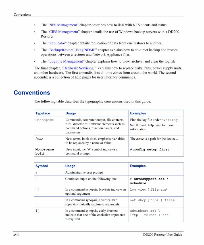
ConventionsThe following table describes the typographic conventions used in this guide.
Typeface Usage Examples
Monospace Commands, computer output, file contents, files, directories, software elements such as command options, function names, and parameters
Find the log file under /var/log.See the net help page for more information.
Italic New terms, book titles, emphasis, variables to be replaced by a name or value
The name is a path for the device...
Monospace bold
User input; the “#” symbol indicates a command prompt.
# config setup first
Symbol Usage Examples
# Administrative user prompt
\ Continued input on the following line # autosupport set \ schedule
[ ] In a command synopsis, brackets indicate an optional argument
log view [filename]
| In a command synopsis, a vertical bar separates mutually exclusive arguments
net dhcp [true | false]
{ } In a command synopsis, curly brackets indicate that one of the exclusive arguments is required.
adminhost add \ {ftp | telnet | ssh}
xviii DD200 Restorer User Guide
Audience
AudienceThis guide is for system administrators who are familiar with general backup administration and one or more backup software packages that Data Domain lists as compatible with a Data Domain restorer. See the Data Domain Support web site, Technical Notes link for the current list of compatible backup packages:
https://support.datadomain.com
Contacting Data DomainFor comments or problems with Data Domain products, contact Data Domain support:
• 24 hours a day, 7 days a week at 877-207-DATA (3282)
• email: [email protected]
For sales and license information:
• 877-207-DATA (3282)
• email: [email protected]
• Fax: 650-424-1057
Data Domain, Incorporated 3400 Hillview Ave. Bldg. 3, 2nd Floor Palo Alto, CA 94304 USA Phone: 650-565-7300 Fax: 650-424-1057
About This Guide xix

Contacting Data Domain
xx DD200 Restorer User Guide
Introduction
1
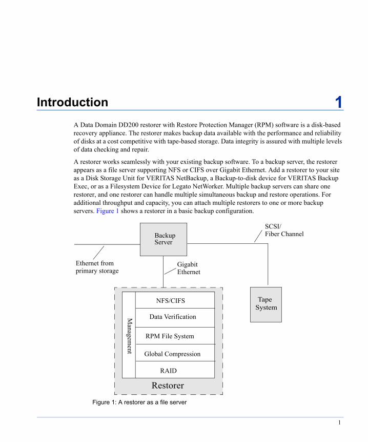
A Data Domain DD200 restorer with Restore Protection Manager (RPM) software is a disk-based recovery appliance. The restorer makes backup data available with the performance and reliability of disks at a cost competitive with tape-based storage. Data integrity is assured with multiple levels of data checking and repair.A restorer works seamlessly with your existing backup software. To a backup server, the restorer appears as a file server supporting NFS or CIFS over Gigabit Ethernet. Add a restorer to your site as a Disk Storage Unit for VERITAS NetBackup, a Backup-to-disk device for VERITAS Backup Exec, or as a Filesystem Device for Legato NetWorker. Multiple backup servers can share one restorer, and one restorer can handle multiple simultaneous backup and restore operations. For additional throughput and capacity, you can attach multiple restorers to one or more backup servers. Figure 1 shows a restorer in a basic backup configuration.
BackupServer
TapeSystem
Restorer
Figure 1: A restorer as a file server
Ethernet from
SCSI/Fiber Channel
primary storageGigabitEthernet
NFS/CIFS
RPM File System
RAID
Managem
ent Global Compression
Data Verification
1

Applications that Send Data to a Restorer
Referring to Figure 1, data flows to a restorer through an Ethernet connection. Immediately, data verification processes begin that follow the data for as long as it is on the restorer. In the file system, Data Domain Global Compression™ algorithms prepare the data for storage. Data is then sent to the disk RAID subsystem. The algorithms constantly adjust the use of storage as the restorer receives new data from backup servers. Restore operations flow back from storage, through decompression algorithms and verification consistency checks, and then through the Ethernet connection to the backup servers.
Applications that Send Data to a RestorerRestorer software is designed specifically for storing relatively large streams of sequential data from backup software and is optimized for high throughput, continuous data verification, and high compression. A restorer makes optimum use of its disk space and compression algorithms when it backs up file systems from 100 MB to 1 TB in size.
Restorer performance when storing data from applications that are not backup software is best when:
• Data is sent to the restorer as sequential writes (no overwrites).
• Files are larger than 1 MB.
• Smaller files are prepackaged with tar (on UNIX-based systems) into units of at least 1 MB in size.
• No compression is used before sending the data to the restorer.
Data IntegrityThe Data Domain Data Invulnerability Architecture™ protects against data loss from hardware and software failures.
• When writing to disk, restorer software creates and stores self-describing metadata for all data received. After writing the data to disk, the restorer then creates metadata from the data on the disk and compares it to the original metadata.
• A strict append-only write policy guards against overwriting valid data.
• After a backup completes, a validation process looks at what was written to disk to see that all file segments are logically correct within the file system and that the data is the same on the disk as it was before being written to disk.
• In the background, the Online Verify operation continuously checks that data on the disks is still correct and that nothing has changed since the earlier validation process.
2 DD200 Restorer User Guide
Data Compression
• The storage disks in a restorer are set up in a mirrored configuration (RAID1+ 0) with hot spares and fast mirror resynchronization. In the case of differences between the mirrors or when the online verify operation finds changed data, the restorer uses the metadata (created when writing data) to determine which mirror has the correct data. The restorer constantly checks for differences and repairs the mirror that has incorrect data.
• To keep data synchronized during a hardware or power failure, the restorer uses NVRAM (non-volatile RAM) to track outstanding I/O operations.
• When reading data back for a restore operation, the restorer uses multiple layers of consistency checks to verify that restored data is correct.
Data CompressionThe Data Domain compression algorithms:
• Store only unique data. Through Global Compression, the restorer pools redundant data from each backup image. Any duplicated data or repeated patterns from multiple backups are stored only once. The storage of unique data is invisible to backup software, which sees the entire virtual file system.
• Are independent of data format. Data can be structured, such as databases, or unstructured, such as text files. Data can be from file systems or raw volumes. All forms are compressed.
Typical compression ratios are 20:1 over 20 weeks assuming weekly full and daily incremental backups. A backup that includes many duplicate or similar files (files copied several times with minor changes) benefits the most from compression.
Depending on backup volume, size, retention period, and rate of change, the amount of compression can vary. The best compression happens with backup volume sizes from 100 MB to 1TB. See “Display File System Space Utilization” on page 56 for details on displaying the amount of user data stored and the amount of space available.
Global Compression functions within a single restorer. To take full advantage of multiple restorers, a site that has more than one restorer should consistently backup the same system or set of data to the same restorer. For example, if a full backup of all sales data goes to restorerA, the incremental backups and future full backups for sales data should also go to restorerA.
Restore OperationsWith disk backup through the restorer, incremental backups are always reliable and access time for files is measured in milliseconds. Furthermore, with a restorer, you can perform full backups more frequently without the penalty of storing redundant data. With tape backups, a restore operation
Chapter 1: Introduction 3
Licensing
may rely on multiple tapes holding incremental backups. Unfortunately, the more incremental backups a site has on multiple tapes, the more time-consuming and risky the restore process. One bad tape can kill the restore.
From a restorer, file restores go quickly and create little contention with backup or other restore operations. Unlike tape drives, multiple processes can access a restorer simultaneously. A restorer allows your site to offer safe, user-driven, single-file restore operations.
LicensingThe licensed features on a restorer are:
• NFS access for backup, restore, and administrative operations from UNIX-based systems.
• CIFS (Common Internet File System) access for backup and restore operations from Windows systems.
• Replication of backup images from one restorer to another.
• Half-size or full-size use of disk storage space. A half-size system has disk space available for half as much data storage as a full system. A restorer with a half-size license can move to full capacity with a license upgrade. No hardware upgrade is necessary.
The license command allows you to add new licenses, delete current licenses, or display current licenses. See “The License Command” on page 34 for command details. Contact your Data Domain representative to purchase licensed features.
Restorer InterfacesAll hardware interfaces are on the back panel of the restorer.
• The DB9 “Console Port” is for an RS232 connection to a serial console. See Figure 4 on page 19. You can use a serial console for administration and configuration tasks.
• One (or optionally three) Gigabit Ethernet ports are for communication with either backup servers or administrative and standard users from remote machines. See Figure 3 on page 18.
• One 10/100 Ethernet port is for communication with either backup servers or administrative and standard users from remote machines. See Figure 3 on page 18.
• One VGA port is for a monitor. See Figure 4 on page 19.
• One port is for a keyboard. Look for the keyboard icon. See Figure 4 on page 19.
4 DD200 Restorer User Guide

Related Documentation
Related Documentation• For technical details about how a restorer functions, ask your Data Domain representative for
the Data Domain publication, DD200 Restorer, An Online Backup and Recovery Storage Appliance.
• See the DD200 Restorer Quick Start folder for a simplified list of installation tasks and the DD200 Restorer Command Reference for restorer command summaries.
Initial System SettingsA restorer as delivered and installed needs very little configuration. When you first log in as sysadmin, the restorer automatically starts the config setup command. After configuration, the following parameters are set in the restorer:
• If using DNS, one to three DNS servers are identified for IP address resolution.
• DHCP is active or not active for each Ethernet interface, as you choose during installation.
• Each active interface has an IP address.
• The restorer hostname is known to the network.
• The restorer knows the addresses to use for the backup servers, SMTP server, and administrative hosts.
• An SMTP (mail) server is identified.
• For NFS clients, the restorer is set up to export the /backup and /ddvar directories using NFSv3 over TCP. For CIFS clients, the restorer has shares set up for /backup and /ddvar.
• One or more backup servers are identified as restorer NFS or CIFS clients.
• A host is identified for restorer administration. Administrative users have access to the partition /ddvar, which holds log files core files, and software release updates. The partition is small and data in the partition is not compressed.
• The system clock uses the time zone you select.
• The only user for the system is sysadmin with the password that you give during setup. The user command allows you to later add administrative and non-administrative users.
• The SSH service is enabled and the FTP and TELNET services are disabled. Use the adminaccess command to enable and disable services.
• The user lists for TELNET and FTP are empty and the protocols are disabled, meaning that no users can connect through TELNET or FTP.
• A weekly system report runs automatically every Sunday at 3 a.m. The report goes to a Data Domain email address and an address that you give during set up. You can add addresses to the email list using the autosupport command.
Chapter 1: Introduction 5
Command Line Interface
• An email list for system alerts that are automatically generated has a Data Domain email address and an address that you give during set up. You can add addresses to the email list using the alerts command
• The clean operation is scheduled for Monday at 1 p.m. To change the schedule, use the filesys clean commands.
• The background verification operation that continuously checks backup images is enabled.
Command Line InterfaceA restorer is administered entirely through a command line interface. Use the SSH or TELNET (if enabled) utilities to access the command prompt. The majority of this manual gives details for using the commands to accomplish specific administration tasks. Each command also has a help page that gives the complete command syntax. Help pages are available through the restorer help command and in an appendix at the back of this manual.
• To list restorer commands, enter a question mark (?) or the help command at the prompt.
• To list the options for a particular command, enter the command with no options at the prompt.
• To find a keyword used in a command option when you do not remember which command to use, enter a question mark (?) or the help command followed by the keyword. For example, the question mark followed by the keyword password displays all restorer command options that include password. If the keyword matches a command, such as net, then the command explanation appears.
• To display a detailed explanation of a particular command, enter a question mark (?) or the help command followed by a command name.
• Use the up and down arrow keys to move through a displayed command. Use the q key to exit. Enter a slash character (/) and a pattern to search for and highlight lines of particular interest.
• The Tab key completes a command entry when that entry is unique. Tab completion works for the first three levels of command components. For example, entering sy(tab) sh(tab) st(tab) displays the command system show stats.
• Any restorer command that accepts a list, such as a list of IP addresses, accepts entries as comma-separated, space-separated, or both.
• Commands that display the use of disk space or the amount of data on disks compute amounts using the following definitions:
1 KB = 210 bytes 1 MB = 220 bytes 1 GB = 230 bytes 1 TB = 240 bytes
6 DD200 Restorer User Guide

Command Line Interface
The commands are:
adminaccess Manages the FTP, TELNET, and SSH services. See “Access Control for Administration” on page 37.
alerts Creates alerts for system problems. Alerts are emailed to Data Domain and to a user-configurable list. See “Alerts” on page 46.
alias Creates aliases for restorer commands See “The Alias Command” on page 87.
autosupport Generates a system status and health report. Reports are emailed to Data Domain and to a user-configurable list. See “Autosupport Reports” on page 49.
cifs Manages Common Internet File System backups and restores and displays CIFS status and statistics. See “CIFS Management” on page 109.
config Shows, resets, copies, and saves restorer configuration settings. See “Configuration Management” on page 31.
disk Displays disk statistics, status, usage, reliability indicators, and RAID layout and usage. See “Disk Management” on page 65.
filesys Displays filesystem status and statistics. See “Statistics and Basic Operations” on page 55 for details. Manages the clean feature that reclaims physical disk space held by deleted data. See “Clean Operations” on page 59 for details.
help Displays a list of all restorer commands and detailed explanations for each command.
license Displays current licensed features and allows adding or deleting licenses.
log Displays and administers the restorer log file. See “Log File Management” on page 133.
ndmp Manages direct backup and restore operations between a Network Appliance™ filer and a restorer using the Network Data Management Protocol. See “Backup/Restore Using NDMP” on page 129.
net Displays network status and set up information. See “Network Management” on page 91.
nfs Displays NFS status and statistics. See “NFS Management” on page 103 for details.
ntp Manages synchronizing a restorer with one or more NTP time servers. See “Time Servers and the NTP Command” on page 88 for details.
replication Manages replication of backup data from one restorer to another. See “Replicator” on page 117.
route Manages restorer network routing rules. See “The Route Command” on page 100.
system Displays restorer status, faults, and statistics, enables, disables, halts, and reboots the restorer. See “The System Command” on page 73. Also sets and displays the system clock and calendar and allows the restorer to synchronize the clock with an external time server. See “Set the Date and Time” on page 77.
Chapter 1: Introduction 7

Command Line Interface
user Administers user accounts for the restorer. See “User Administration” on page 41 for details.
8 DD200 Restorer User Guide

Disk Space Management
2
This chapter:• Gives general guidelines for predicting how much disk space your site may use over time.
• Explains how to deal with restorer components that run out of disk space.
• Describes the use of the Data Domain Space Management Tool.
Note Data Domain offers guidance on setting up third-party backup software and backup servers for use with a restorer. Because such information tends to change often, the information is available on the Data Domain Support web site (http://support.datadomain .com/). See the Technical Notes section.
Space ManagementThe restorer is designed as a very reliable online cache for backups. As new backups are added to the system, old backups are removed. Such removals are normally done under the control of backup software (on the backup server) based on the configured retention period. The process with a restorer is very similar to tape policies where older backups are retired and the tapes are reused for new backups.
When backup software removes an old backup from a restorer, the space on the restorer becomes available only after the weekly clean function reclaims disk space. A good way to manage space on a restorer is to retain as many online backups as possible with some headroom (about 20% of total space available) to allow for data growth over time.
Data growth on a restorer is primarily affected by:
• The size and compressibility of the primary storage that you are backing up.
• The retention period that you specify with the backup software.
If you backup volumes of over 1 TB in size or the retention time for volumes that do not compress well is greater than four months, backups may use space on a restorer more quickly than expected.
9

Estimate Use of Disk Space
Estimate Use of Disk SpaceThe restorer’s use of compression when storing data means that you can look at the use of disk space in two ways: physical and virtual. (See “Data Compression” on page 3 for details about compression.) Physical space is the actual disk space used on the restorer. Virtual space is the amount of space needed if all data and multiple backup images were uncompressed.
• Through the restorer, the filesys show space command (or the aliased df) shows both physical and virtual space. See “Manage File System Use of Disk Space” on page 12.
• From NFS clients:
- Use df -k /<mountpoint> to display the physical space used for data storage and the space available in kilobytes.
- Use du -s /<mountpoint> to display the amount of virtual (uncompressed) data, in 512 byte blocks, that the backup server sees on the restorer (divide by 2 to get kilobytes).
- The ls(1m) command also shows the amount of virtual data.
The restorer generates log messages as the file system approaches its maximum size. The following information about data compression gives guidelines for disk use over time.
The amount of disk space used over time by a restorer depends on:
• The size of the initial full backup.
• The number of backups (incremental and full) over time.
• The rate of growth for data in the backups.
For data sets with average rates of change and growth, data compression generally matches the following guidelines:
• For the first full backup to a restorer, the compression factor is about 3:1. Disk space used on the restorer is about one-third the size of the data before the backup.
• Each incremental backup to the initial full backup has a compression factor of about 6:1.
• The next full backup has a compression factor of about 60:1. All data that was new or changed in the incremental backups is already in storage.
• Over time, the aggregate compression factor for all the data is about 20:1.
Table 1 gives rough guidelines for how long data sets of various sizes can be backed up to a restorer when no data is expired and deleted. The actual retention time for a given site varies according to the dependencies detailed above.
10 DD200 Restorer User Guide
Reclaim Data Storage Disk Space
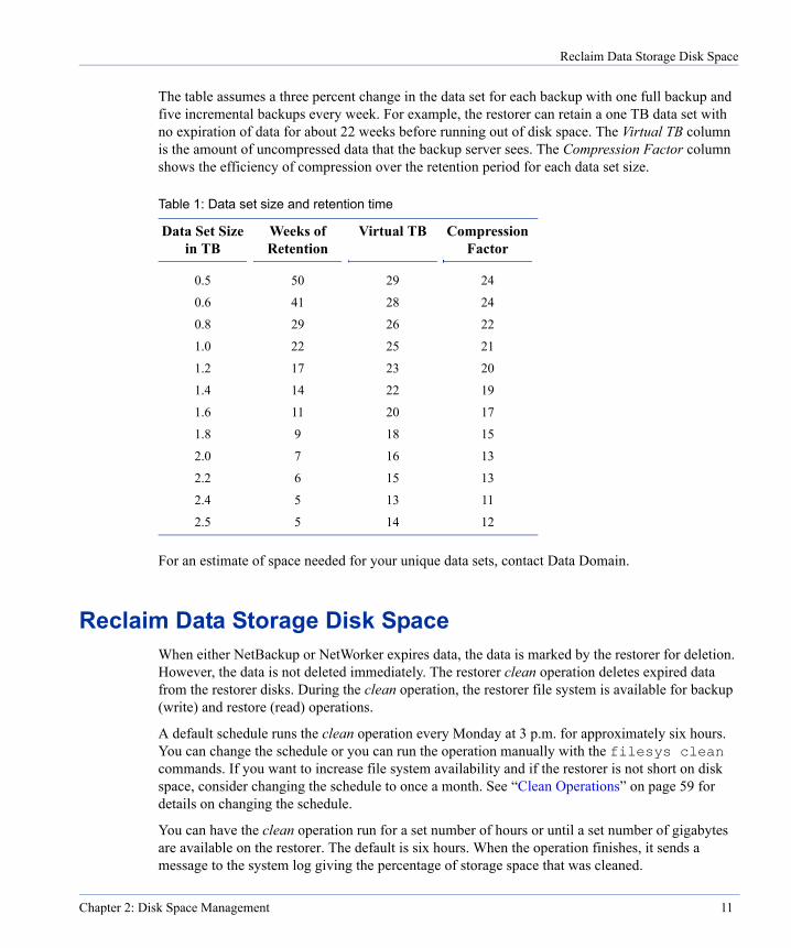
The table assumes a three percent change in the data set for each backup with one full backup and five incremental backups every week. For example, the restorer can retain a one TB data set with no expiration of data for about 22 weeks before running out of disk space. The Virtual TB column is the amount of uncompressed data that the backup server sees. The Compression Factor column shows the efficiency of compression over the retention period for each data set size.
For an estimate of space needed for your unique data sets, contact Data Domain.
Reclaim Data Storage Disk SpaceWhen either NetBackup or NetWorker expires data, the data is marked by the restorer for deletion. However, the data is not deleted immediately. The restorer clean operation deletes expired data from the restorer disks. During the clean operation, the restorer file system is available for backup (write) and restore (read) operations.
A default schedule runs the clean operation every Monday at 3 p.m. for approximately six hours. You can change the schedule or you can run the operation manually with the filesys clean commands. If you want to increase file system availability and if the restorer is not short on disk space, consider changing the schedule to once a month. See “Clean Operations” on page 59 for details on changing the schedule.
You can have the clean operation run for a set number of hours or until a set number of gigabytes are available on the restorer. The default is six hours. When the operation finishes, it sends a message to the system log giving the percentage of storage space that was cleaned.
Table 1: Data set size and retention time
Data Set Size in TB
Weeks of Retention
Virtual TB Compression Factor
0.5 50 29 24
0.6 41 28 24
0.8 29 26 22
1.0 22 25 21
1.2 17 23 20
1.4 14 22 19
1.6 11 20 17
1.8 9 18 15
2.0 7 16 13
2.2 6 15 13
2.4 5 13 11
2.5 5 14 12
Chapter 2: Disk Space Management 11

Manage File System Use of Disk Space
Manage File System Use of Disk SpaceThe restorer command filesys show space (or the alias command df) displays the amount of disk space used for data storage and for restorer components.
# filesys show space Resource Size GB Used GB Avail GB Use% ------------------------------------------------------ /ddvar 18.3 10.2 8.1 59% /backup (compressed data collection) Pre-compression - 219.3 - - Compressed Data 670.6 22.1 648.5 3% If 100% cleaned* 670.6 22.1 648.5 3% Meta Data 92.0 1.5 90.6 2% Index 10.8 0.5 10.3 5% Estimated compression factor*: 9.1x = 219.3/(22.1+1.5+0.5) * Estimate based on 2004/06/16 cleaning
• The /ddvar line gives a rough idea of the amount of space used by and available to the log and core files. Remove old logs and core files to free space in this area.
• The Pre-compression line shows the amount of virtual data stored on the restorer. Virtual data is the amount of data sent to the restorer from backup servers.
• The Compressed section, Data line shows the actual physical space used by and available for data storage. Warning messages go to the system log and an email alert is generated when the Use% figure reaches 90%, 95%, and 100%. At 100%, the restorer accepts no more data from backup servers. You must run a filesys clean operation to reclaim disk space. If Use% is always high, use the filesys clean show-schedule command to see how often the operation runs automatically, then use filesys clean schedule to run the operation more often.
Also consider reducing the data retention period or splitting off a portion of the backup to another restorer.
• The If 100% cleaned line is an estimate of actual physical space used, and physical space available for data storage if you run the filesys clean start all operation to clean 100% of the file system. The estimate is based on the most recent clean operation.
• The Meta Data line tracks space used for the internal file descriptions that the restorer creates for all stored files. Warning messages go to the system log and an email alert is generated when the Use% figure reaches 90%, 95%, and 100%. At 100%, the restorer accepts no more data from backup servers. From the backup server, you must expire or purge backup images to create free space for meta data.
12 DD200 Restorer User Guide

Display the Space Usage Graph
• The Index line tracks space used for internal restorer operations. Warning messages go to the system log and an email alert is generated when the Use% figure reaches 90%, 95%, and 100%. At 100%, the restorer accepts no more data from backup servers. To create free space for the index:
- From the backup server, expire or purge backup images.
- On the restorer, run the filesys clean start operation.
• The Estimated compression ratio line gives a rough idea of data compression efficiency. The estimate is based on the most recent clean operation and changes if the compressibility of data sent to the restorer changes. Note that the compression algorithm includes the metadata and index space as part of the total storage space.
Display the Space Usage GraphThe Data Domain Support web site includes graphs of disk space usage and compression for every restorer that sends autosupport reports to Data Domain. The graphs display a history of disk space usage, a compression ratio, and the total amount of data sent to the restorer. Use the graphs to see how disk space is used on a restorer with your current data retention policies. Vertical drops in each line show when one or more clean processes remove expired data. From the Support web site, select Space Usage Plots.
The plots on the graph are:
• Cumulative Physical The total amount of physical storage in use on the restorer. Look at the left vertical axis of the graph for the total number of gigabytes used for storage.
• Compression Ratio The amount of compression the restorer has done with all of the data received. Look at the right vertical axis of the graph for the compression ratio.
• Cumulative Virtual The total amount of data sent to the restorer by backup servers. Virtual data on a restorer is what a backup server sees as the total un-compressed data held by a restorer-as-storage-unit. Look at the left vertical axis of the graph for the total number of gigabytes of data sent to the restorer.
Chapter 2: Disk Space Management 13

Display the Space Usage Graph
Figure 2 shows an example of the display.
Figure 2: Space usage graph
CumulativeVirtual
CompressionRatio
CumulativePhysical
14 DD200 Restorer User Guide
Installation
3
Installation and site configuration for the DD200 restorer consist of the tasks listed below. After configuration, the restorer is fully functional and ready for backups. For site hardware and backup software requirements, see “Restorer Interfaces” on page 4.• Check the site and backup software requirements.
• To use DHCP with Ethernet interfaces, configure the DHCP server with the appropriate restorer information. To configure a restorer using an Ethernet interface, DHCP information is required for at least one interface. The alternative is to use a serial console or a keyboard and monitor.
• Set up the restorer hardware.
• Set up a serial console or a monitor and keyboard if you are not using an Ethernet interface for configuration.
• Login to the restorer as sysadmin using a serial console, or monitor and keyboard, or SSH and an Ethernet interface.
• Answer questions asked by the configuration process that starts automatically when sysadmin first logs in. The process requests all of the basic information needed to use the restorer.
• Optionally, after completing the initial configuration, follow the steps in “Additional Configuration” on page 29 to add to the configuration.
• Configure the backup software and servers. See the Data Domain Support web site (https://support.datadomain.com), Technical Notes section for details about configuring a restorer with specific backup servers and software.
For upgrading restorer software to a new release, see “Upgrade Restorer Software” on page 74.
Note Software is pre-installed on the restorer. You do not need to install software. The Install and Rescue CD attached to the back cover of this manual is for emergency situations, such as when a restorer fails to boot up by itself. In such a situation, please call Data Domain Technical Support for step-by-step instructions.
15

Site Requirements
Site RequirementsTo install a restorer at your site, you need:
• A 4U space in a standard 19 inch rack. A restorer in a rack has the following requirements:
- Air conditioning that can cope with the system’s maximum thermal rating of 1,000 BTUs an hour.
- The ambient air temperature range is 5° C to 35° C at the front panel of the chassis.
- Ventilation and air flow through the front and back panels of the restorer is critical. The restorer requires six inches of unobstructed clearance for both the front panel and the back panel. Do not block or cover the openings in the front and back panels.
- In a closed or multi-unit rack, ensure that the unit has adequate airflow and that the ambient air temperature requirements are met.
• For configuration and administrative tasks, either a serial console, an Ethernet connection, or a keyboard and monitor.
• An Ethernet connection to a restorer interface for data transfer to and from backup servers.
- Jumbo frames are supported for the Gigabit Ethernet interfaces.
- If the restorer uses Fiber Gigabit Ethernet interfaces, the cables and connecting ports on the other end must be SX compatible.
• The restorer is shipped with grounding type (three wire) power cords. To reduce the risk of electric shock, always use the cords with grounded power outlets.
• Single phase AC power systems with a grounded neutral conductor. To reduce the risk of electric shock, do not power the restorer from any other type of power system. Input characteristics:
- Voltage: 100 to 240 VAC Full Range.
- Frequency: 50 to 60 Hz.
- Power required during the first six seconds after power-on: 650W.
- Power required during normal operation: 300W. Measurements on typical systems indicate a power requirement of 250 to 300 watts.
- Input Current: 9.0 / 5.0 A for 115 / 230 VAC.
- Inrush Current: 80A / 100A max. for 115 / 230 VAC for each power module.
• Ensure that the circuit used for the restorer is not overloaded. Look for the power ratings on the nameplates of all equipment on the circuit. The total load on the circuit should not exceed the maximum circuit rating. Note that the restorer requires about 650W during the first six seconds after power-on and about 300W during normal operation.
16 DD200 Restorer User Guide
Backup Software Requirements
Backup Software RequirementsA restorer accepts data from many combinations of backup software and servers. See the Data Domain Support web site (https://support.datadomain.com), Compatibility Matrix section for the latest updates on supported backup software and server combinations.
Note See the Data Domain Support web site, Technical Notes section for configuration details for using specific backup software and server types with a restorer.
CIFS Backup Server TimeoutInternal activities on a Data Domain restorer can take longer than a default CIFS timeout, leading to an error message from the media server. The message is similar to: Network name no longer existed. On all CIFs backup servers using a restorer, change the SESSTIMEOUT value from the default of 45 (seconds) to 300 (five minutes).
• If you want detailed background information, see the following web page:
http://support.microsoft.com/default.aspx?scid=http://support.mocrosoft.com:80/support/kb/ articles/Q102/0/67.asp&NoWebContent=1
• Open REGEDT32 and navigate to:
HKEY_LOCAL_MACHINE\SYSTEM\CURRENTCONTROLSET\SERVICES\ LANMANWORKSTATION\PARAMTERS
• If the SESSTIMEOUT key does not exist, click in the right panel and select New and DWORD value. Create a new key, SESSTIMEOUT. Note that the registry is case sensitive. Use all caps for the new key name.
• Double click on the new (or existing) key and set the value to 300.
DHCP ServerIf one or more of the restorer Ethernet interfaces are to use DHCP, the DHCP server needs MAC addresses for the interfaces and a hostname for the restorer. Data Domain recommends configuring infinite lease IP addresses for the restorer interfaces. All of the interfaces do not need to use DHCP.
If you set an interface to use DHCP and DHCP is not yet available to the interface, the restorer attempts to set up the interface without DHCP until DHCP is available. Use the net show settings command to display which interfaces are configured for DHCP.
Chapter 3: Installation 17

Hardware Installation
Each Ethernet interface on the back of the restorer is labeled with its MAC address. See Figure 3. Eth0 is a 10/100 Base-T interface. Eth1 is a copper 1000 Base-T gigabit interface. The optional eth2 and eth3 are for additional Fiber or copper Ethernet interfaces. The MAC addresses for eth0 and eth1 are vertical labels just to the right of each port. The MAC addresses for eth2 and eth3 are vertical labels just above eth2. The label on the left is for eth2 and the label on the right is for eth3.
Hardware InstallationCaution The two side brackets on the restorer’s front faceplate (see Figure 6 on page 20) cannot
support the weight of the restorer. In a rack, support the restorer with slide rails.
• Mount the restorer in a 4U space in a 19-inch, four-post rack using the slide rails provided by Data Domain. Any other means of mounting the restorer must be rated for at least 100 pounds (45 kilograms).
- Open the slide rails package that ships with the restorer.
- Using the instruction sheet included with the slide rails, mount the slide rail guides onto the restorer. Make sure that the front and back rail mounting faces are parallel with each other and with the front panel of the rack. Make sure that both rails are horizontal.
- Mount the slide rails onto the rack.
- Slide the restorer into the rack.
• Determine whether your configuration and ongoing administration access for the restorer is to be through an Ethernet connection, a serial console, or a monitor and keyboard.
- For a serial console, attach an RS232 cable to the DB9 port (labeled “Console Port”) on the back panel. See Figure 4. Use the console communication settings of: 9600 baud, 8 data bits, no parity, 1 stop bit.
Figure 3: Ethernet interfaceseth0 eth1 eth2 eth3
18 DD200 Restorer User Guide
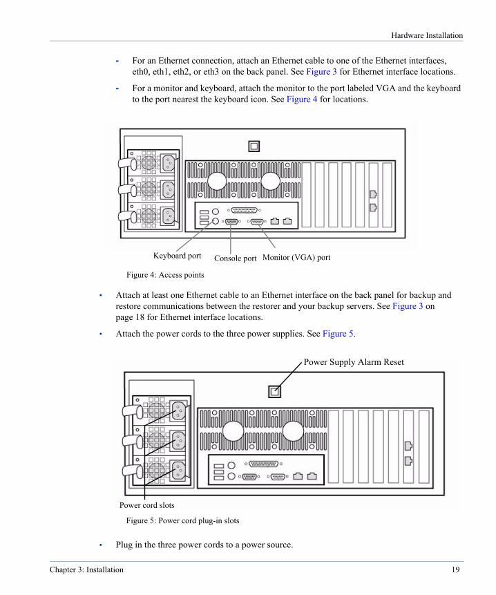
Hardware Installation
- For an Ethernet connection, attach an Ethernet cable to one of the Ethernet interfaces, eth0, eth1, eth2, or eth3 on the back panel. See Figure 3 for Ethernet interface locations.
- For a monitor and keyboard, attach the monitor to the port labeled VGA and the keyboard to the port nearest the keyboard icon. See Figure 4 for locations.
• Attach at least one Ethernet cable to an Ethernet interface on the back panel for backup and restore communications between the restorer and your backup servers. See Figure 3 on page 18 for Ethernet interface locations.
• Attach the power cords to the three power supplies. See Figure 5.
• Plug in the three power cords to a power source.
Figure 4: Access points
Console port Monitor (VGA) portKeyboard port
Figure 5: Power cord plug-in slots
Power cord slots
Power Supply Alarm Reset
Chapter 3: Installation 19
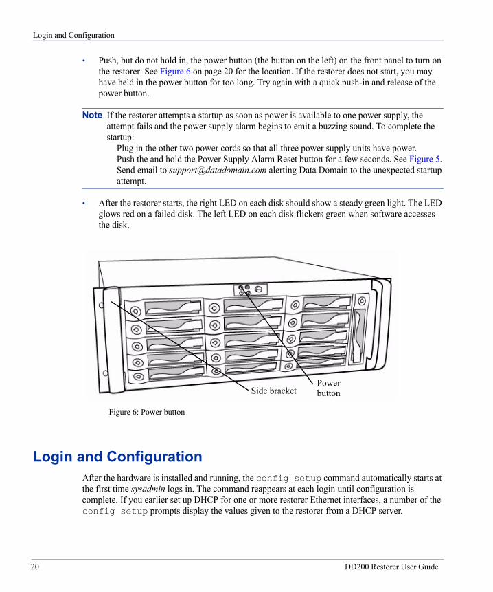
Login and Configuration
• Push, but do not hold in, the power button (the button on the left) on the front panel to turn on the restorer. See Figure 6 on page 20 for the location. If the restorer does not start, you may have held in the power button for too long. Try again with a quick push-in and release of the power button.
Note If the restorer attempts a startup as soon as power is available to one power supply, the attempt fails and the power supply alarm begins to emit a buzzing sound. To complete the startup:
Plug in the other two power cords so that all three power supply units have power. Push the and hold the Power Supply Alarm Reset button for a few seconds. See Figure 5. Send email to [email protected] alerting Data Domain to the unexpected startup attempt.
• After the restorer starts, the right LED on each disk should show a steady green light. The LED glows red on a failed disk. The left LED on each disk flickers green when software accesses the disk.
Login and ConfigurationAfter the hardware is installed and running, the config setup command automatically starts at the first time sysadmin logs in. The command reappears at each login until configuration is complete. If you earlier set up DHCP for one or more restorer Ethernet interfaces, a number of the config setup prompts display the values given to the restorer from a DHCP server.
Figure 6: Power button
PowerbuttonSide bracket
20 DD200 Restorer User Guide
Login and Configuration
DHCP servers normally supply values for a number of networking parameters. Press Return during the installation to accept DHCP values. If you do not use DHCP for an interface, determine what you will use for the following values before starting the configuration:
• Interface IP addresses.
• Interface netmasks.
• Routing gateway.
• DNS server list (if using DNS).
• A site domain name, such as yourcompany.com.
• A fully-qualified hostname for the restorer, such as dd01.yourcompany.com.
When configuring restorer software:
• At any prompt, enter a question mark (?) for detailed information about the prompt.
• Press Return to accept a displayed value.
• Enter either hostnames or IP addresses where ever a prompt mentions a host. Hostnames must be fully qualified, such as srvr22.yourcompany.com.
• For any entry that accepts a list, the entries in the list can be comma-separated, space- separated, or both.
• When configuration is complete, the system is ready to accept backup data. For NFS clients, the restorer is set up to export the /backup and /ddvar directories using NFSv3 over TCP. For CIFS clients, the restorer has shares set up for /backup and /ddvar.
The configuration utility has five sections. You can configure or skip over any section.
To begin the configuration:
1. The first login to the restorer can be from a serial console, keyboard and monitor, or through an Ethernet connection. Log in as user sysadmin. The default password is the serial number that appears on the rear panel of the restorer. See Figure 7 for the location. You can change the password as explained in step 7 on page 28.
- From a serial console or keyboard and monitor, log in to the restorer at the login prompt.
- From a remote machine over an Ethernet connection, give the following command (with the hostname you chose for the restorer) and then give the default password.
# ssh -l sysadmin host-name sysadmin@host-name’s password:
Chapter 3: Installation 21
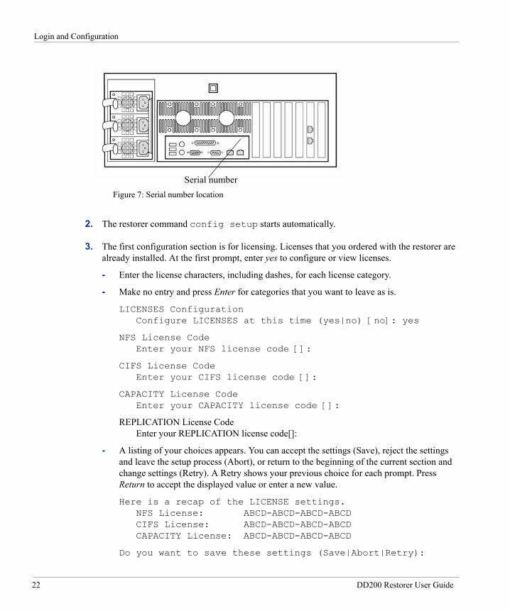
Login and Configuration
2. The restorer command config setup starts automatically.
3. The first configuration section is for licensing. Licenses that you ordered with the restorer are already installed. At the first prompt, enter yes to configure or view licenses.
- Enter the license characters, including dashes, for each license category.
- Make no entry and press Enter for categories that you want to leave as is.
LICENSES Configuration Configure LICENSES at this time (yes|no) [no]: yes
NFS License Code Enter your NFS license code []:
CIFS License Code Enter your CIFS license code []:
CAPACITY License Code Enter your CAPACITY license code []:
REPLICATION License Code Enter your REPLICATION license code[]:
- A listing of your choices appears. You can accept the settings (Save), reject the settings and leave the setup process (Abort), or return to the beginning of the current section and change settings (Retry). A Retry shows your previous choice for each prompt. Press Return to accept the displayed value or enter a new value.
Here is a recap of the LICENSE settings. NFS License: ABCD-ABCD-ABCD-ABCD CIFS License: ABCD-ABCD-ABCD-ABCD CAPACITY License: ABCD-ABCD-ABCD-ABCD
Do you want to save these settings (Save|Abort|Retry):
Serial numberFigure 7: Serial number location
22 DD200 Restorer User Guide

Login and Configuration
4. The second section is for network configuration. At the first prompt, enter yes to configure network parameters.
Note After configuring the restorer to use DNS, the restorer must be rebooted. Also, if DHCP is disabled for all interfaces and then later enabled for one or more interfaces, the restorer must be rebooted.
NETWORK Configuration Configure NETWORK parameters at this time (yes|no) [no]:
a. The first prompt is for a restorer machine name. Enter a fully-qualified name that includes the domain name. For example: dd01.yourcompany.com.
Hostname Enter the hostname for this system (fully-qualified domain name)[]:
b. Supply a domain name, such as yourcompany.com, for use by restorer utilities, or accept the display of the domain name used in the hostname.
Domainname Enter your DNS domainname []:
c. Configure each Ethernet interface that has an active Ethernet connection. If you earlier set up DHCP for an interface, the IP address and netmask prompts do not appear. You can accept or not accept DHCP for each interface.
- If you enter yes for DHCP and DHCP is not yet available to the interface, the restorer attempts to set up the interface with DHCP until DHCP is available. Use the net show settings command to display which interfaces are configured for DHCP.
- If you are on an Ethernet interface and you choose to not use DHCP for the interface, the connection is lost when you complete the configuration.
- At the last prompt, entering an a (Abort) exits the configuration utility.
- The first interface (eth0) is a 10/100 Base-T Ethernet connection. The other three interfaces (eth1, eth2, and eth3) are Gigabit Ethernet connections. The same set of prompts appears for each interface.
Ethernet port eth0: Enable this port (yes|no) [ ]: Use DHCP on this port (yes|no) [ ]: IP Address []: Netmask [ ]:
- When not using DHCP on any Ethernet port, you must specify an IP address for a default routing gateway.
Chapter 3: Installation 23
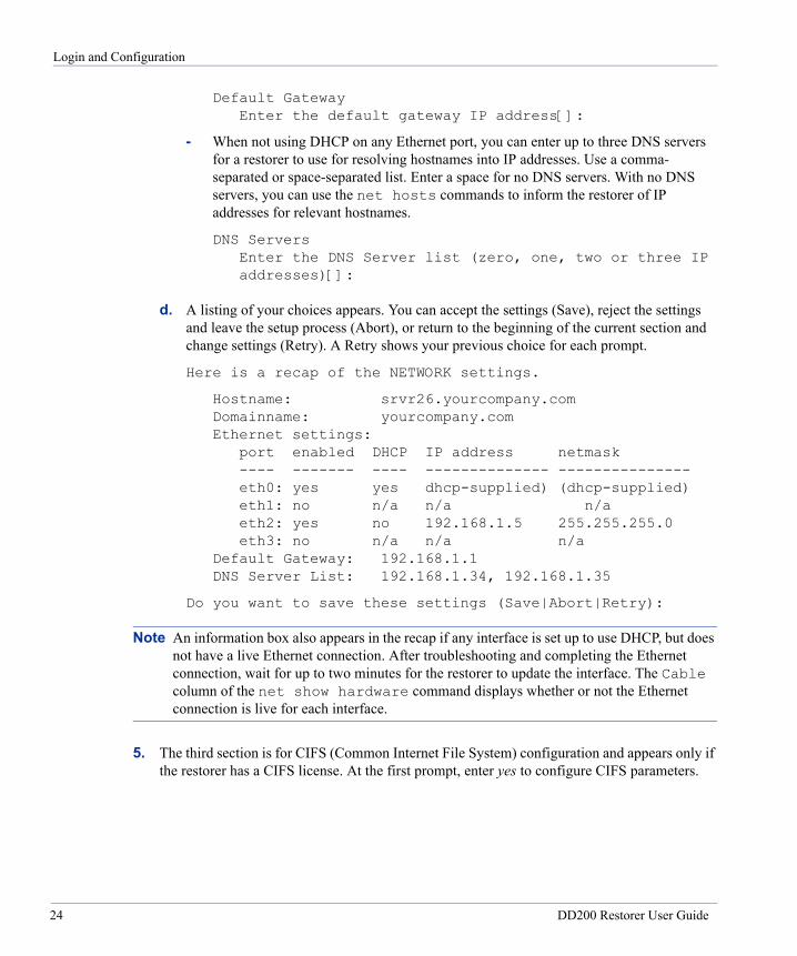
Login and Configuration
Default Gateway Enter the default gateway IP address[]:
- When not using DHCP on any Ethernet port, you can enter up to three DNS servers for a restorer to use for resolving hostnames into IP addresses. Use a comma- separated or space-separated list. Enter a space for no DNS servers. With no DNS servers, you can use the net hosts commands to inform the restorer of IP addresses for relevant hostnames.
DNS Servers Enter the DNS Server list (zero, one, two or three IP addresses)[]:
d. A listing of your choices appears. You can accept the settings (Save), reject the settings and leave the setup process (Abort), or return to the beginning of the current section and change settings (Retry). A Retry shows your previous choice for each prompt.
Here is a recap of the NETWORK settings.
Hostname: srvr26.yourcompany.com Domainname: yourcompany.com Ethernet settings:
port enabled DHCP IP address netmask ---- ------- ---- -------------- --------------- eth0: yes yes dhcp-supplied) (dhcp-supplied) eth1: no n/a n/a n/a eth2: yes no 192.168.1.5 255.255.255.0 eth3: no n/a n/a n/a
Default Gateway: 192.168.1.1 DNS Server List: 192.168.1.34, 192.168.1.35
Do you want to save these settings (Save|Abort|Retry):
Note An information box also appears in the recap if any interface is set up to use DHCP, but does not have a live Ethernet connection. After troubleshooting and completing the Ethernet connection, wait for up to two minutes for the restorer to update the interface. The Cable column of the net show hardware command displays whether or not the Ethernet connection is live for each interface.
5. The third section is for CIFS (Common Internet File System) configuration and appears only if the restorer has a CIFS license. At the first prompt, enter yes to configure CIFS parameters.
24 DD200 Restorer User Guide

Login and Configuration
Note Every user account from outside a restorer that needs access to a restorer must have a local account on the restorer, even when using Active Directory as the access mode. After the installation, give access to restorer shares using the command line interface on the restorer. Use the user add command to add users and the cifs add command to add client machines from which users access the restorer.
CIFS Configuration Configure CIFS at this time (yes|no) [no]: yes
a. Select a user-authentication method for the CIFS user accounts that connect to the /backup and /ddvar shares on the restorer.
CIFS Authentication Which authentication method will this system use (Workgroup|Domain|Active-Directory) [ ]:
The Workgroup method has the following prompts. Enter a workgroup, the name of a CIFS backup account and password, a WINS server name, and backup server names.
Workgroup Name Enter the workgroup name for this system [ ]: Do you want to add a backup user yes|no) [no]:
Backup User Enter backup user name:
Backup User Password Enter backup user password:
Enter the WINS server for the restorer to use:
WINS Server Enter the IP address for the WINS server for this system []:
Enter one or more backup servers as restorer clients.
Backup Servers Enter the Backup Server list (CIFS clients of /backup) []:
The Domain method brings the following prompts. Enter a domain name, the name of a CIFS backup account, one or more domain controller IP addresses, a WINS server name, and backup server names. Press Enter with no entry to break out of the prompts for domain controllers.
Chapter 3: Installation 25

Login and Configuration
Domain Name Enter the name of the Windows domain for this system [ ]: Do you want to add a backup user? (yes|no) [no]:
Backup user Enter backup user name:
Domain Controller Enter the IP address of domain controller 1 for this system [ ]:
Enter the WINS server for the restorer to use:
WINS Server Enter the IP address for the WINS server for this system []:
Enter one or more backup servers as restorer clients.
Backup Servers Enter the Backup Server list (CIFS clients of /backup) []:
The Active-Directory method brings the following prompts. Enter a fully-qualfied realm name, the name of a CIFS backup account, a WINS server name, and backup server names. Data Domain recommends not specifying a domain controller. When not using a domain controller, be sure to specify a WINS server. The restorer must meet all active-directory requirments, such as a clock time that is no more than five minutes different than the domain controller. Press Enter with no entry to break out of the prompts for domain controllers.
Active-Directory Realm Enter the name of the Active-Directory Realm for this system [ ]:
Do you want to add a backup user? (yes|no) [no]:
Backup user Enter backup user name:
Domain Controller Enter the IP address of domain controller 1 for this system [ ]:
Enter the WINS server for the restorer to use:
WINS Server Enter the IP address for the WINS server for this system []:
26 DD200 Restorer User Guide
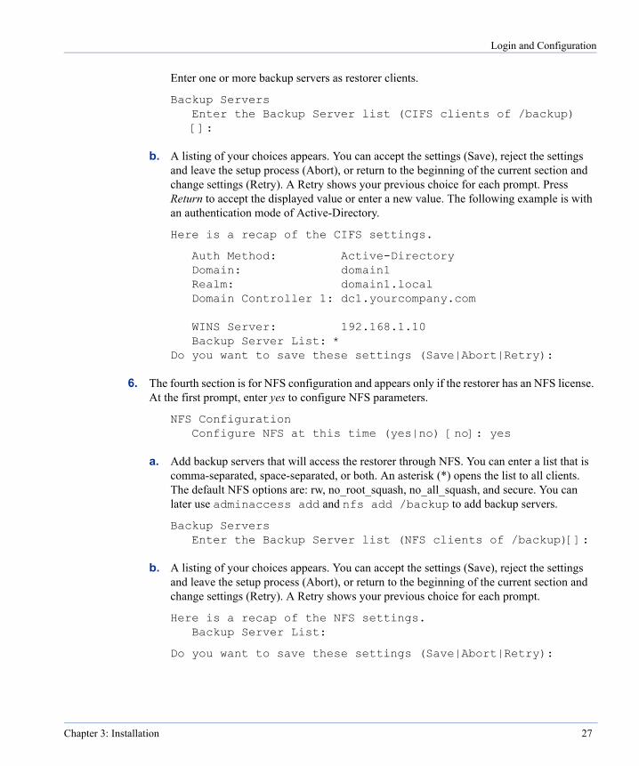
Login and Configuration
Enter one or more backup servers as restorer clients.
Backup Servers Enter the Backup Server list (CIFS clients of /backup) []:
b. A listing of your choices appears. You can accept the settings (Save), reject the settings and leave the setup process (Abort), or return to the beginning of the current section and change settings (Retry). A Retry shows your previous choice for each prompt. Press Return to accept the displayed value or enter a new value. The following example is with an authentication mode of Active-Directory.
Here is a recap of the CIFS settings.
Auth Method: Active-Directory Domain: domain1 Realm: domain1.local Domain Controller 1: dc1.yourcompany.com
WINS Server: 192.168.1.10 Backup Server List: *
Do you want to save these settings (Save|Abort|Retry):
6. The fourth section is for NFS configuration and appears only if the restorer has an NFS license. At the first prompt, enter yes to configure NFS parameters.
NFS Configuration Configure NFS at this time (yes|no) [no]: yes
a. Add backup servers that will access the restorer through NFS. You can enter a list that is comma-separated, space-separated, or both. An asterisk (*) opens the list to all clients. The default NFS options are: rw, no_root_squash, no_all_squash, and secure. You can later use adminaccess add and nfs add /backup to add backup servers.
Backup Servers Enter the Backup Server list (NFS clients of /backup)[]:
b. A listing of your choices appears. You can accept the settings (Save), reject the settings and leave the setup process (Abort), or return to the beginning of the current section and change settings (Retry). A Retry shows your previous choice for each prompt.
Here is a recap of the NFS settings. Backup Server List:
Do you want to save these settings (Save|Abort|Retry):
Chapter 3: Installation 27

Login and Configuration
7. The fifth section is for system parameters. At the first prompt, enter yes to configure system parameters.
SYSTEM Configuration Configure SYSTEM Parameters at this time (yes|no) [no]:
a. You can change the sysadmin password. Re-enter the password for verification:
Sysadmin Password Do you want to change the sysadmin password? (yes|no) [no]: Enter new password: Re-enter new password:
b. Add a client host from which you will administer the restorer. The default NFS options are: rw, no_root_squash, no_all_squash, and secure. You can later use the commands adminaccess add and nfs add /ddvar to add other administrative hosts.
Admin host Enter a hostname for administrative access to the restorer []:
c. You can add an email address so that someone at your site receives email for system alerts and autosupport reports. For example, [email protected]. By default, the restorer email lists include an address for the Data Domain support group. You can later use the restorer commands alerts and autosupport to add more addresses.
Admin email Enter an email address or group alias that will receive email from the restorer. The address is also used as the ‘From’ address in all email sent by the restorer []:
d. You can enter a location description for ease of identifying the physical machine. For example, Bldg4-rack10. The alerts and autosupport reports display the location.
System Location Enter a physical location, to better identify this system []:
e. Enter the name of a local SMTP (mail) server for restorer emails. If the server is an Exchange server, be sure that SMTP is enabled.
SMTP Server Enter the hostname of a mail server to relay email alerts []:
28 DD200 Restorer User Guide
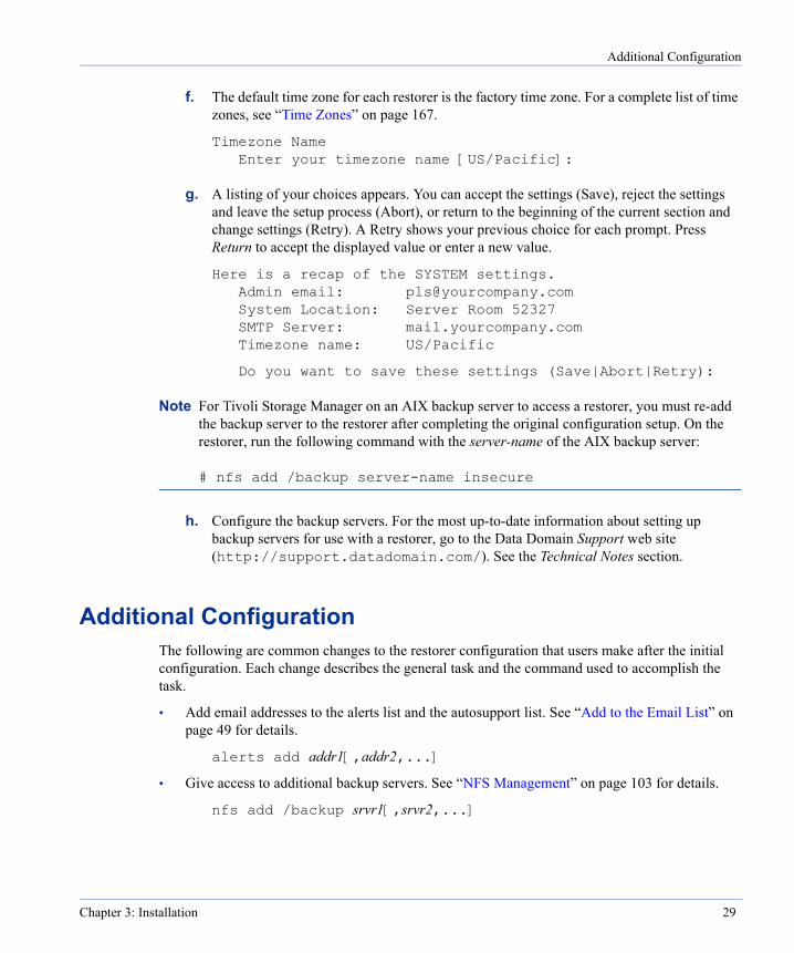
Additional Configuration
f. The default time zone for each restorer is the factory time zone. For a complete list of time zones, see “Time Zones” on page 167.
Timezone Name Enter your timezone name [US/Pacific]:
g. A listing of your choices appears. You can accept the settings (Save), reject the settings and leave the setup process (Abort), or return to the beginning of the current section and change settings (Retry). A Retry shows your previous choice for each prompt. Press Return to accept the displayed value or enter a new value.
Here is a recap of the SYSTEM settings. Admin email: [email protected] System Location: Server Room 52327 SMTP Server: mail.yourcompany.com Timezone name: US/Pacific
Do you want to save these settings (Save|Abort|Retry):
Note For Tivoli Storage Manager on an AIX backup server to access a restorer, you must re-add the backup server to the restorer after completing the original configuration setup. On the restorer, run the following command with the server-name of the AIX backup server: # nfs add /backup server-name insecure
h. Configure the backup servers. For the most up-to-date information about setting up backup servers for use with a restorer, go to the Data Domain Support web site (http://support.datadomain.com/). See the Technical Notes section.
Additional ConfigurationThe following are common changes to the restorer configuration that users make after the initial configuration. Each change describes the general task and the command used to accomplish the task.
• Add email addresses to the alerts list and the autosupport list. See “Add to the Email List” on page 49 for details.
alerts add addr1[,addr2,...]
• Give access to additional backup servers. See “NFS Management” on page 103 for details.
nfs add /backup srvr1[,srvr2,...]
Chapter 3: Installation 29

Administering a Restorer
• From a remote machine, add an authorized SSH public key to the restorer. See “Add an Authorized SSH Public Key” on page 38 for details.
ssh-keygen -d ssh -l sysadmin rstr01 “adminaccess add ssh-keys” \ < ~/.ssh/id_dsa.pub
• Add remote hosts that can use FTP or TELNET on the restorer. See “Add a Host” on page 37 for details.
adminaccess add {ftp | telnet}{all | host1[,host2,...]}
• Enable FTP or TELNET. The SSH service is enabled by default. See “Enable a Protocol” on page 38 for details.
adminaccess enable {ftp | telnet | ssh | all}
• Add a standard user. See “User Administration” on page 41 for details.
user add username
• Change a user password. See “User Administration” on page 41 for details.
user change password username
Administering a RestorerThe remaining chapters in this book detail the use of all restorer commands and operations. The headings in each chapter are a task-oriented list of operations performed by the featured commands. To find the command for any task that you want to perform, do either of the following:
• Look in the table of contents at the beginning of this guide for the heading that describes the task.
• List the restorer commands and operations. To see a list of commands, log in to the restorer using SSH (or TELNET if that is enabled) and enter a question mark (?) at the prompt. To see a list of operations available for a particular command, enter the command name. To display a detailed help page for a command, use the help command with the name of the target command. Use the up and down arrow keys to move through a displayed command. Use the q key to exit. Enter a slash character (/) and a pattern to search for and highlight lines of particular interest.
30 DD200 Restorer User Guide
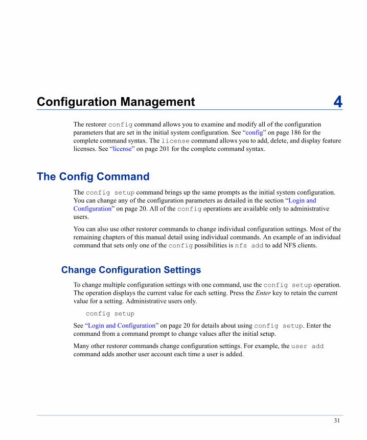
Configuration Management
4
The restorer config command allows you to examine and modify all of the configuration parameters that are set in the initial system configuration. See “config” on page 186 for the complete command syntax. The license command allows you to add, delete, and display feature licenses. See “license” on page 201 for the complete command syntax.The Config CommandThe config setup command brings up the same prompts as the initial system configuration. You can change any of the configuration parameters as detailed in the section “Login and Configuration” on page 20. All of the config operations are available only to administrative users.
You can also use other restorer commands to change individual configuration settings. Most of the remaining chapters of this manual detail using individual commands. An example of an individual command that sets only one of the config possibilities is nfs add to add NFS clients.
Change Configuration SettingsTo change multiple configuration settings with one command, use the config setup operation. The operation displays the current value for each setting. Press the Enter key to retain the current value for a setting. Administrative users only.
config setup
See “Login and Configuration” on page 20 for details about using config setup. Enter the command from a command prompt to change values after the initial setup.
Many other restorer commands change configuration settings. For example, the user add command adds another user account each time a user is added.
31
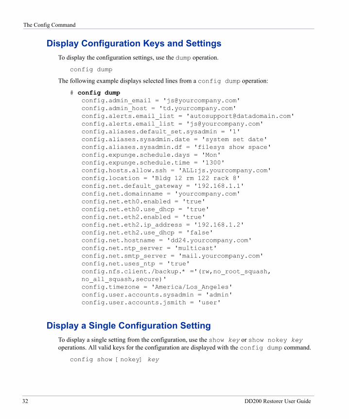
The Config Command
Display Configuration Keys and SettingsTo display the configuration settings, use the dump operation.
config dump
The following example displays selected lines from a config dump operation:
# config dump config.admin_email = '[email protected]' config.admin_host = 'td.yourcompany.com' config.alerts.email_list = '[email protected]' config.alerts.email_list = '[email protected]' config.aliases.default_set.sysadmin = '1' config.aliases.sysadmin.date = 'system set date' config.aliases.sysadmin.df = 'filesys show space' config.expunge.schedule.days = 'Mon' config.expunge.schedule.time = '1300' config.hosts.allow.ssh = 'ALL:js.yourcompany.com' config.location = 'Bldg 12 rm 122 rack 8' config.net.default_gateway = '192.168.1.1' config.net.domainname = 'yourcompany.com' config.net.eth0.enabled = 'true' config.net.eth0.use_dhcp = 'true' config.net.eth2.enabled = 'true' config.net.eth2.ip_address = '192.168.1.2' config.net.eth2.use_dhcp = 'false' config.net.hostname = 'dd24.yourcompany.com' config.net.ntp_server = 'multicast' config.net.smtp_server = 'mail.yourcompany.com' config.net.uses_ntp = 'true' config.nfs.client./backup.* ='(rw,no_root_squash, no_all_squash,secure)' config.timezone = 'America/Los_Angeles' config.user.accounts.sysadmin = 'admin' config.user.accounts.jsmith = 'user'
Display a Single Configuration SettingTo display a single setting from the configuration, use the show key or show nokey key operations. All valid keys for the configuration are displayed with the config dump command.
config show [nokey] key
32 DD200 Restorer User Guide
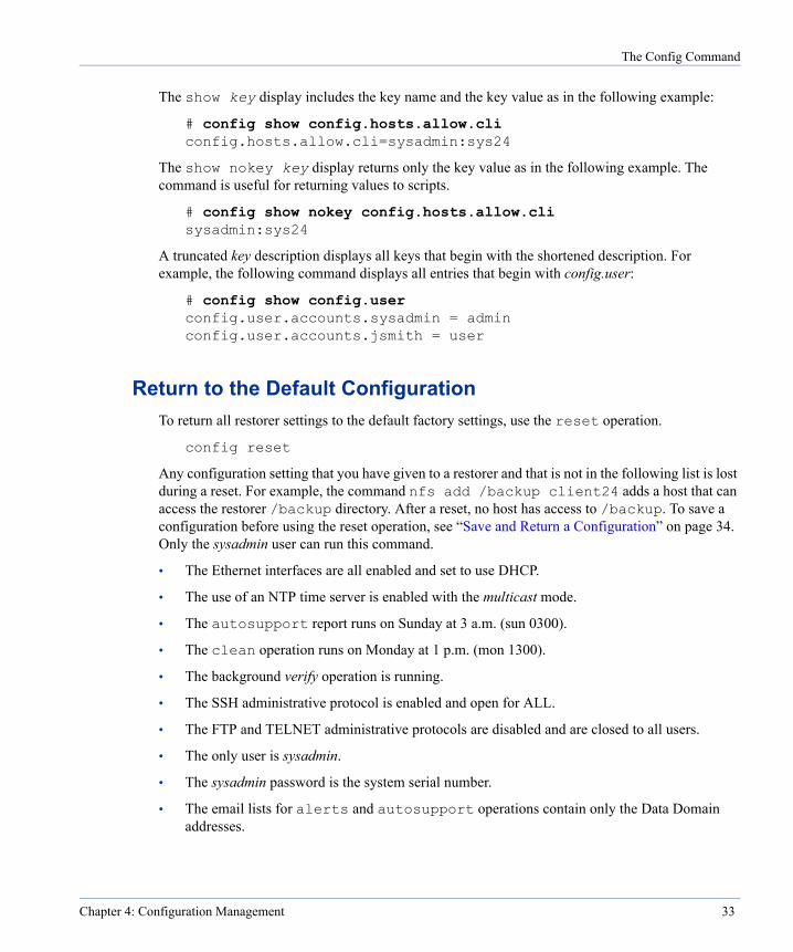
The Config Command
The show key display includes the key name and the key value as in the following example:
# config show config.hosts.allow.cli config.hosts.allow.cli=sysadmin:sys24
The show nokey key display returns only the key value as in the following example. The command is useful for returning values to scripts.
# config show nokey config.hosts.allow.cli sysadmin:sys24
A truncated key description displays all keys that begin with the shortened description. For example, the following command displays all entries that begin with config.user:
# config show config.user config.user.accounts.sysadmin = admin config.user.accounts.jsmith = user
Return to the Default ConfigurationTo return all restorer settings to the default factory settings, use the reset operation.
config reset
Any configuration setting that you have given to a restorer and that is not in the following list is lost during a reset. For example, the command nfs add /backup client24 adds a host that can access the restorer /backup directory. After a reset, no host has access to /backup. To save a configuration before using the reset operation, see “Save and Return a Configuration” on page 34. Only the sysadmin user can run this command.
• The Ethernet interfaces are all enabled and set to use DHCP.
• The use of an NTP time server is enabled with the multicast mode.
• The autosupport report runs on Sunday at 3 a.m. (sun 0300).
• The clean operation runs on Monday at 1 p.m. (mon 1300).
• The background verify operation is running.
• The SSH administrative protocol is enabled and open for ALL.
• The FTP and TELNET administrative protocols are disabled and are closed to all users.
• The only user is sysadmin.
• The sysadmin password is the system serial number.
• The email lists for alerts and autosupport operations contain only the Data Domain addresses.
Chapter 4: Configuration Management 33

The License Command
Save and Return a ConfigurationUsing SSH, you can direct output from the restorer config dump command, which returns all restorer configuration settings, into a file on a remote host from which you do restorer administration. You can later use SSH to return the file to the restorer, which immediately recognizes the settings as a configuration and accepts the settings as the current configuration.
For example, the following command connects with the restorer dd10 as user sysadmin, asks for the password, returns output from the command config dump that is run on the restorer, and stores the output in the local file (remote from the restorer) /tmp/config12:
# ssh -l sysadmin dd10 config dump > /tmp/config12 sysadmin@dd10’s password:
config.aliases.default_set.root = '1' config.aliases.default_set.sysadmin = '1' config.aliases.sysadmin.df = 'filesys show space' config.aliases.sysadmin.halt = 'system poweroff'
The following command returns the configuration settings from the file /tmp/config12 to the restorer. The settings immediately become the current configuration for the restorer.
# ssh -l sysadmin dd10 < /tmp/config12 sysadmin@dd10’s password: Reloading configuration: (CHECKED) Security access lists (from adminaccess) updated Bringing up DHCP client daemon for eth0... Bringing up DHCP client daemon for eth2...
The License CommandThe license command manages licensed features on a restorer.
Add a LicenseTo add a feature license, use the add operation. The code for each license is a string of 16 letters with dashes. Include the dashes when entering the license code. Administrative users only.
The licensed features are:
• CAPACITY-FULLSIZE Use all the disk space on a restorer. When upgrading from HALF to FULL, simply add the FULL license. The HALF license is automatically replaced and the increased disk space is immediately available.
• CAPACITY-HALFSIZE Use only half the disk space on a restorer.
• NFS Do backups, restores, and administration from NFS clients.
34 DD200 Restorer User Guide
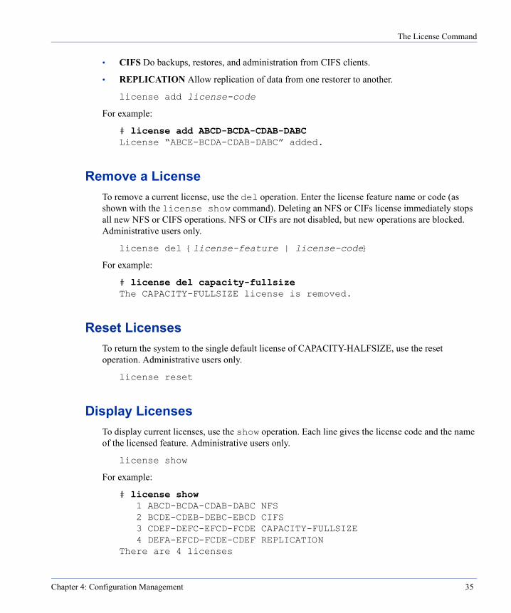
The License Command
• CIFS Do backups, restores, and administration from CIFS clients.
• REPLICATION Allow replication of data from one restorer to another.
license add license-code
For example:
# license add ABCD-BCDA-CDAB-DABC License “ABCE-BCDA-CDAB-DABC” added.
Remove a LicenseTo remove a current license, use the del operation. Enter the license feature name or code (as shown with the license show command). Deleting an NFS or CIFs license immediately stops all new NFS or CIFS operations. NFS or CIFs are not disabled, but new operations are blocked. Administrative users only.
license del {license-feature | license-code}
For example:
# license del capacity-fullsize The CAPACITY-FULLSIZE license is removed.
Reset LicensesTo return the system to the single default license of CAPACITY-HALFSIZE, use the reset operation. Administrative users only.
license reset
Display LicensesTo display current licenses, use the show operation. Each line gives the license code and the name of the licensed feature. Administrative users only.
license show
For example:
# license show 1 ABCD-BCDA-CDAB-DABC NFS 2 BCDE-CDEB-DEBC-EBCD CIFS 3 CDEF-DEFC-EFCD-FCDE CAPACITY-FULLSIZE 4 DEFA-EFCD-FCDE-CDEF REPLICATION
There are 4 licenses
Chapter 4: Configuration Management 35

The License Command
36 DD200 Restorer User Guide
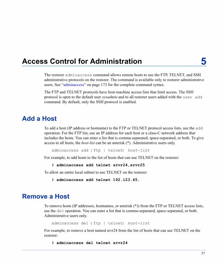
Access Control for Administration
5
The restorer adminaccess command allows remote hosts to use the FTP, TELNET, and SSH administrative protocols on the restorer. The command is available only to restorer administrative users. See “adminaccess” on page 173 for the complete command syntax.The FTP and TELNET protocols have host-machine access lists that limit access. The SSH protocol is open to the default user sysadmin and to all restorer users added with the user add command. By default, only the SSH protocol is enabled.
Add a HostTo add a host (IP address or hostname) to the FTP or TELNET protocol access lists, use the add operation. For the FTP list, use an IP address for each host or a class-C network address that includes the hosts. You can enter a list that is comma-separated, space-separated, or both. To give access to all hosts, the host-list can be an asterisk (*). Administrative users only.
adminaccess add {ftp | telnet} host-list
For example, to add hosts to the list of hosts that can use TELNET on the restorer:
# adminaccess add telnet srvr24,srvr25
To allow an entire local subnet to use TELNET on the restorer:
# adminaccess add telnet 192.123.45.
Remove a HostTo remove hosts (IP addresses, hostnames, or asterisk (*)) from the FTP or TELNET access lists, use the del operation. You can enter a list that is comma-separated, space-separated, or both. Administrative users only.
adminaccess del {ftp | telnet} host-list
For example, to remove a host named srvr24 from the list of hosts that can use TELNET on the restorer:
# adminaccess del telnet srvr24
37

Reset a List
Reset a ListBy default, FTP and TELNET are disabled and have no entries in their access lists. SSH is enabled. No one is able to use FTP or TELNET unless the appropriate access list has one or more host entries. The reset operation returns the FTP and TELNET protocols to the default state of disabled with no entries and sets SSH to enabled. Administrative users only.
adminaccess reset {ftp | telnet | ssh | all}
For example, to reset the FTP list to an empty list and reset FTP to disabled:
# adminaccess reset ftp
Enable a ProtocolBy default, only the SSH service is enabled. FTP and TELNET are disabled. The enable operation enables a protocol on the restorer. Note that to use FTP and TELNET, you must also add host machines to the access lists. Administrative users only.
adminaccess enable {ftp | telnet | ssh | all}
For example, to enable the FTP service:
# adminaccess enable ftp
Disable a ProtocolTo disable a service on the restorer, use the disable operation. Disabling FTP or TELNET does not affect entries in the access lists. If all services are disabled, the restorer is accessible only through a serial console or keyboard and monitor. Administrative users only.
adminaccess disable {ftp | telnet | ssh | all}
For example, to disable the FTP service:
# adminaccess disable ftp
Add an Authorized SSH Public KeyAdding an authorized SSH public key to the SSH key file on a restorer is done from a machine that will access the restorer. Adding a key allows a user to log in from the remote machine to the restorer without entering a password. Available only to the user sysadmin. After creating a key on the remote machine, use the add ssh-keys operation. Administrative users only.
adminaccess add ssh-keys
38 DD200 Restorer User Guide
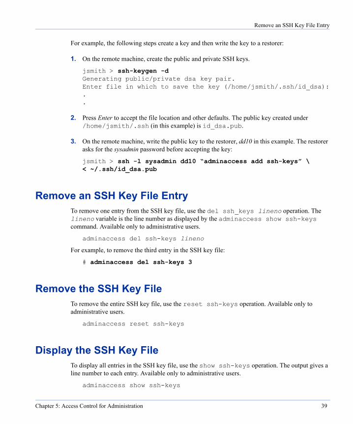
Remove an SSH Key File Entry
For example, the following steps create a key and then write the key to a restorer:
1. On the remote machine, create the public and private SSH keys.
jsmith > ssh-keygen -d Generating public/private dsa key pair. Enter file in which to save the key (/home/jsmith/.ssh/id_dsa): . .
2. Press Enter to accept the file location and other defaults. The public key created under /home/jsmith/.ssh (in this example) is id_dsa.pub.
3. On the remote machine, write the public key to the restorer, dd10 in this example. The restorer asks for the sysadmin password before accepting the key:
jsmith > ssh -l sysadmin dd10 “adminaccess add ssh-keys” \ < ~/.ssh/id_dsa.pub
Remove an SSH Key File EntryTo remove one entry from the SSH key file, use the del ssh_keys lineno operation. The lineno variable is the line number as displayed by the adminaccess show ssh-keys command. Available only to administrative users.
adminaccess del ssh-keys lineno
For example, to remove the third entry in the SSH key file:
# adminaccess del ssh-keys 3
Remove the SSH Key FileTo remove the entire SSH key file, use the reset ssh-keys operation. Available only to administrative users.
adminaccess reset ssh-keys
Display the SSH Key FileTo display all entries in the SSH key file, use the show ssh-keys operation. The output gives a line number to each entry. Available only to administrative users.
adminaccess show ssh-keys
Chapter 5: Access Control for Administration 39
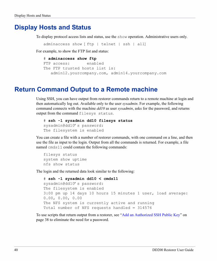
Display Hosts and Status
Display Hosts and StatusTo display protocol access lists and status, use the show operation. Administrative users only.
adminaccess show [ftp | telnet | ssh | all]
For example, to show the FTP list and status:
# adminaccess show ftp FTP access: enabled The FTP trusted hosts list is:
admin12.yourcompany.com, admin14.yourcompany.com
Return Command Output to a Remote machineUsing SSH, you can have output from restorer commands return to a remote machine at login and then automatically log out. Available only to the user sysadmin. For example, the following command connects with the machine dd10 as user sysadmin, asks for the password, and returns output from the command filesys status.
# ssh -l sysadmin dd10 filesys status sysadmin@dd10’s password: The filesystem is enabled
You can create a file with a number of restorer commands, with one command on a line, and then use the file as input to the login. Output from all the commands is returned. For example, a file named cmds11 could contain the following commands:
filesys status system show uptime nfs show status
The login and the returned data look similar to the following:
# ssh -l sysadmin dd10 < cmds11 sysadmin@dd10’s password: The filesystem is enabled 3:00 pm up 14 days 10 hours 15 minutes 1 user, load average: 0.00, 0.00, 0.00 The NFS system is currently active and running Total number of NFS requests handled = 314576
To use scripts that return output from a restorer, see “Add an Authorized SSH Public Key” on page 38 to eliminate the need for a password.
40 DD200 Restorer User Guide

User Administration
6
The restorer command user adds, removes, and displays users and changes user passwords. A restorer has two classes of user accounts. The user class is for standard users who have access to a limited number of commands. Most of the user commands display information. The admin class is administrative users who have access to all restorer commands. The default administrative account is sysadmin. You can change the sysadmin password, but cannot delete the account.Throughout this manual, command explanations include text similar to the following for commands or operations that standard users cannot access: Available to administrative users only. See “user” on page 245 for the complete command syntax.
Add a UserTo add a restorer user, use the add user-name operation. The operation asks for a password and confirmation or you can include the password as part of the command. Each user has a privilege level of either admin or user. User is the default. The only way to change a user’s privilege level is to delete the user and then add the user with the other privilege level. Available to administrative users only.
user add user-name [password password][priv {admin | user}]
For example, to add a user with a login name of jsmith, a password of usr256, and administrative privilege:
# user add jsmith password usr256 priv admin
Remove a UserTo remove a user from a restorer, use the del user-name operation. Available to administrative users only.
user del user-name
For example, to remove a user with a login name of jsmith:
# user del jsmith user jsmith removed
41
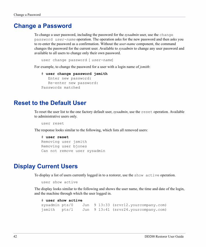
Change a Password
Change a PasswordTo change a user password, including the password for the sysadmin user, use the change password user-name operation. The operation asks for the new password and then asks you to re-enter the password as a confirmation. Without the user-name component, the command changes the password for the current user. Available to sysadmin to change any user password and available to all users to change only their own password.
user change password [user-name]
For example, to change the password for a user with a login name of jsmith:
# user change password jsmith Enter new password: Re-enter new password:
Passwords matched
Reset to the Default UserTo reset the user list to the one factory default user, sysadmin, use the reset operation. Available to administrative users only.
user reset
The response looks similar to the following, which lists all removed users:
# user reset Removing user jsmith Removing user bjones Can not remove user sysadmin
Display Current UsersTo display a list of users currently logged in to a restorer, use the show active operation.
user show active
The display looks similar to the following and shows the user name, the time and date of the login, and the machine through which the user logged in.
# user show active sysadmin pts/0 Jun 9 13:33 (srvr12.yourcompany.com) jsmith pts/1 Jun 9 13:41 (srvr24.yourcompany.com)
42 DD200 Restorer User Guide
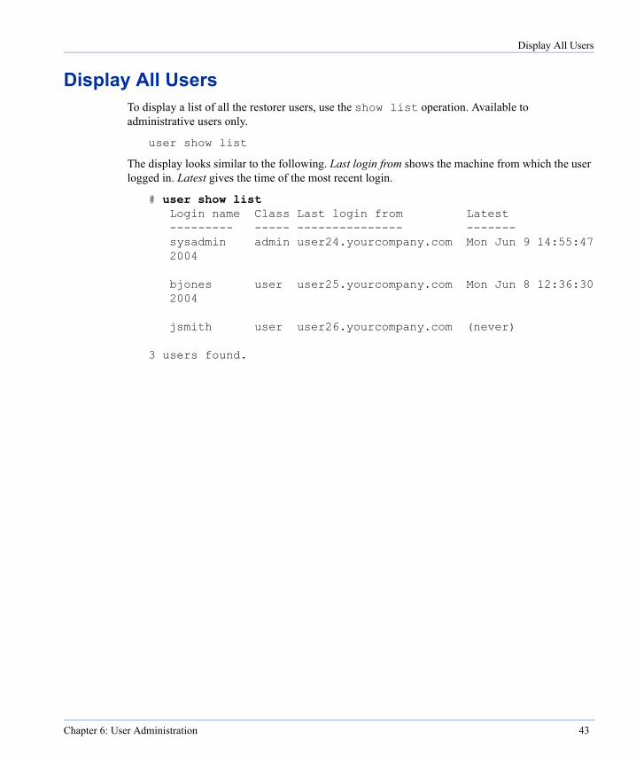
Display All Users
Display All UsersTo display a list of all the restorer users, use the show list operation. Available to administrative users only.
user show list
The display looks similar to the following. Last login from shows the machine from which the user logged in. Latest gives the time of the most recent login.
# user show list Login name Class Last login from Latest --------- ----- --------------- ------- sysadmin admin user24.yourcompany.com Mon Jun 9 14:55:47 2004
bjones user user25.yourcompany.com Mon Jun 8 12:36:30 2004
jsmith user user26.yourcompany.com (never)
3 users found.
Chapter 6: User Administration 43

Display All Users
44 DD200 Restorer User Guide
Alerts and System Reports
7
A restorer uses multiple methods to inform administrators about the status of software and hardware. The restorer alerts, autosupport, and AM email features send messages and reports to user-configurable lists of email addresses. The lists include an email address for Data Domain support staff who monitor the status of all restorers and contact your company when problems are reported. The messages also go to the system log.• The alerts feature sends an email whenever a critical component in the system fails or is known, through monitoring, to be out of an acceptable range. Consider adding pager email addresses to the alerts email list so that someone is informed immediately about system problems. For example, a single fan failure is not critical and does not generate an alert as the system can continue normal operations; however, multiple fan failures can cause a system to begin overheating, which generates an alerts email.
Each disk, fan, and CPU in the restorer is monitored. Temperature extremes are also monitored. See “Display Hardware Status” on page 78 for details about hardware monitoring. See “alerts” on page 176 for the complete command syntax.
• The autosupport feature sends a daily report that shows system identification information and consolidates the output from a number of restorer commands. See “Run the Autosupport Report” on page 51 for details. Data Domain support staff use the report for troubleshooting. See “autosupport” on page 180 for the complete command syntax.
• Every morning at 8:00 a.m., the restorer sends an AM email to the autosupport email list. The purpose is to highlight hardware or other failures that are not critical, but that should be dealt with soon. An example would be a fan failure. A failed fan should be replaced as soon as is reasonably possible, but the system can continue operations.
The AM email is a copy of output from alerts show current (see “Display Current Alerts” on page 47) and alerts show history (see “Display the Alerts History” on page 48), messages about non-critical hardware situations, and some disk space usage numbers.
• Non-critical hardware problems generate email messages to the autosupport list. An example is a failed power supply when the other two power supplies are still fine. If the situation is not fixed, the message also appears in the AM email.
• Every hour, the restorer logs a short system status message. See “Hourly System Status” on page 54 for details.
45
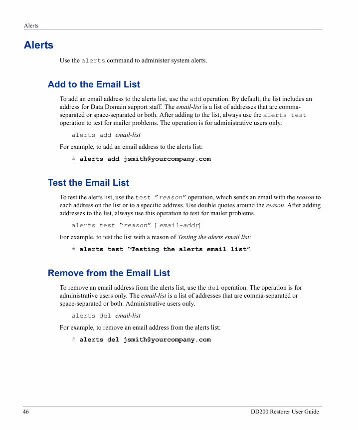
Alerts
AlertsUse the alerts command to administer system alerts.
Add to the Email ListTo add an email address to the alerts list, use the add operation. By default, the list includes an address for Data Domain support staff. The email-list is a list of addresses that are comma- separated or space-separated or both. After adding to the list, always use the alerts test operation to test for mailer problems. The operation is for administrative users only.
alerts add email-list
For example, to add an email address to the alerts list:
# alerts add [email protected]
Test the Email ListTo test the alerts list, use the test ”reason” operation, which sends an email with the reason to each address on the list or to a specific address. Use double quotes around the reason. After adding addresses to the list, always use this operation to test for mailer problems.
alerts test “reason” [email-addr]
For example, to test the list with a reason of Testing the alerts email list:
# alerts test “Testing the alerts email list”
Remove from the Email ListTo remove an email address from the alerts list, use the del operation. The operation is for administrative users only. The email-list is a list of addresses that are comma-separated or space-separated or both. Administrative users only.
alerts del email-list
For example, to remove an email address from the alerts list:
# alerts del [email protected]
46 DD200 Restorer User Guide
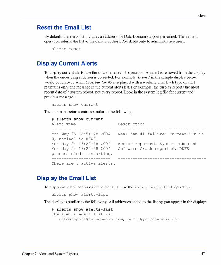
Alerts
Reset the Email ListBy default, the alerts list includes an address for Data Domain support personnel. The reset operation returns the list to the default address. Available only to administrative users.
alerts reset
Display Current AlertsTo display current alerts, use the show current operation. An alert is removed from the display when the underlying situation is corrected. For example, Event 1 in the sample display below would be removed when Crossbar fan #5 is replaced with a working unit. Each type of alert maintains only one message in the current alerts list. For example, the display reports the most recent date of a system reboot, not every reboot. Look in the system log file for current and previous messages.
alerts show current
The command returns entries similar to the following:
# alerts show current Alert Time Description ------------------------ ------------------------------------ Mon May 25 18:54:48 2004 Rear fan #1 failure: Current RPM is 0, nominal is 8000 Mon May 24 16:22:58 2004 Reboot reported. System rebooted Mon May 24 16:22:58 2004 Software Crash reported. DDFS process died; restarting. ------------------------ ------------------------------------ There are 3 active alerts.
Display the Email ListTo display all email addresses in the alerts list, use the show alerts-list operation.
alerts show alerts-list
The display is similar to the following. All addresses added to the list by you appear in the display:
# alerts show alerts-list The Alerts email list is:
[email protected], [email protected]
Chapter 7: Alerts and System Reports 47
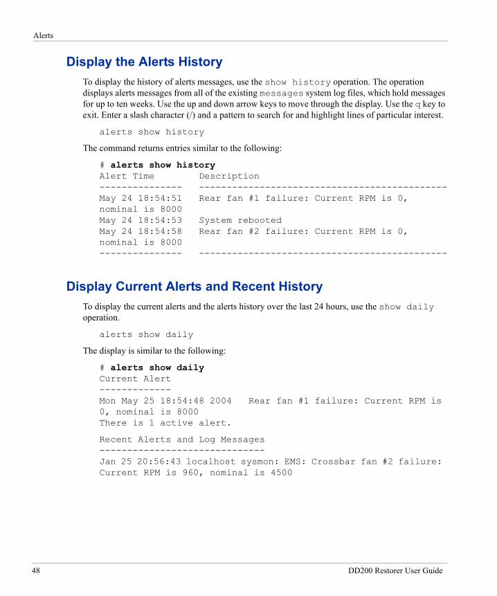
Alerts
Display the Alerts HistoryTo display the history of alerts messages, use the show history operation. The operation displays alerts messages from all of the existing messages system log files, which hold messages for up to ten weeks. Use the up and down arrow keys to move through the display. Use the q key to exit. Enter a slash character (/) and a pattern to search for and highlight lines of particular interest.
alerts show history
The command returns entries similar to the following:
# alerts show history Alert Time Description --------------- --------------------------------------------- May 24 18:54:51 Rear fan #1 failure: Current RPM is 0, nominal is 8000 May 24 18:54:53 System rebooted May 24 18:54:58 Rear fan #2 failure: Current RPM is 0, nominal is 8000 --------------- ---------------------------------------------
Display Current Alerts and Recent HistoryTo display the current alerts and the alerts history over the last 24 hours, use the show daily operation.
alerts show daily
The display is similar to the following:
# alerts show daily Current Alert ------------- Mon May 25 18:54:48 2004 Rear fan #1 failure: Current RPM is 0, nominal is 8000 There is 1 active alert.
Recent Alerts and Log Messages ------------------------------ Jan 25 20:56:43 localhost sysmon: EMS: Crossbar fan #2 failure: Current RPM is 960, nominal is 4500
48 DD200 Restorer User Guide

Autosupport Reports
Display the Email List and Administrator EmailTo display all email addresses in the alerts list and the system administrator email address, use the show all operation.
alerts show all
The display is similar to the following. The administrator address appears twice:
# alerts show all The Admin email is: [email protected] The Alerts email list is:
[email protected], [email protected]
Autosupport ReportsUse the autosupport command to administer the autosupport reports feature.
Add to the Email ListTo add an email address to the autosupport report list, use the add operation. By default, the list includes an address for Data Domain support staff. The email-list is a list of addresses that are comma-separated or space-separated or both. After adding to the list, always use the autosupport send operation to test for mailer problems. Administrative users only.
autosupport add email-list
For example, to add a an email address to the list:
# autosupport add [email protected]
Remove from the Email ListTo remove an email address from the autosupport report list, use the del operation. The operation is available only to administrative users. The email-list is a list of addresses that are comma-separated or space-separated or both. Administrative users only.
autosupport del email-list
For example, to remove an email address from the list:
# autosupport del [email protected]
Chapter 7: Alerts and System Reports 49
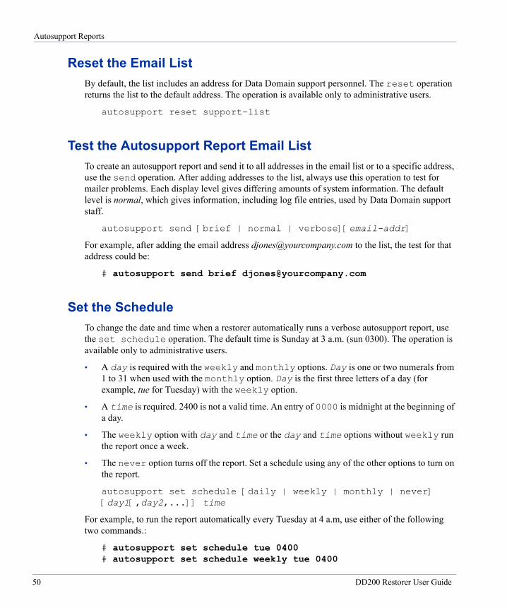
Autosupport Reports
Reset the Email ListBy default, the list includes an address for Data Domain support personnel. The reset operation returns the list to the default address. The operation is available only to administrative users.
autosupport reset support-list
Test the Autosupport Report Email ListTo create an autosupport report and send it to all addresses in the email list or to a specific address, use the send operation. After adding addresses to the list, always use this operation to test for mailer problems. Each display level gives differing amounts of system information. The default level is normal, which gives information, including log file entries, used by Data Domain support staff.
autosupport send [brief | normal | verbose][email-addr]
For example, after adding the email address [email protected] to the list, the test for that address could be:
# autosupport send brief [email protected]
Set the ScheduleTo change the date and time when a restorer automatically runs a verbose autosupport report, use the set schedule operation. The default time is Sunday at 3 a.m. (sun 0300). The operation is available only to administrative users.
• A day is required with the weekly and monthly options. Day is one or two numerals from 1 to 31 when used with the monthly option. Day is the first three letters of a day (for example, tue for Tuesday) with the weekly option.
• A time is required. 2400 is not a valid time. An entry of 0000 is midnight at the beginning of a day.
• The weekly option with day and time or the day and time options without weekly run the report once a week.
• The never option turns off the report. Set a schedule using any of the other options to turn on the report.
autosupport set schedule [daily | weekly | monthly | never] [day1[,day2,...]] time
For example, to run the report automatically every Tuesday at 4 a.m, use either of the following two commands.:
# autosupport set schedule tue 0400 # autosupport set schedule weekly tue 0400
50 DD200 Restorer User Guide
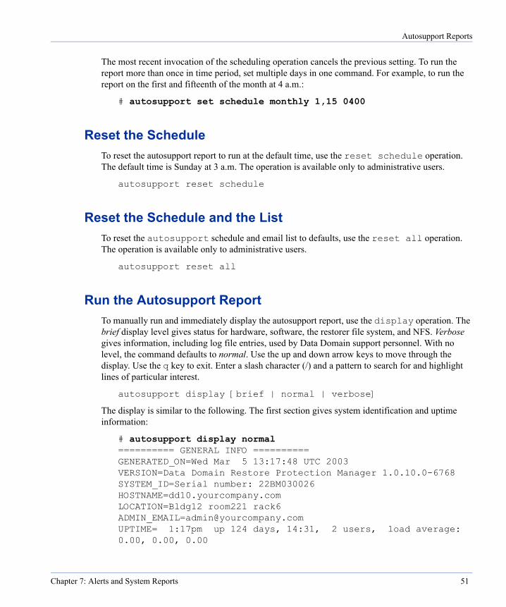
Autosupport Reports
The most recent invocation of the scheduling operation cancels the previous setting. To run the report more than once in time period, set multiple days in one command. For example, to run the report on the first and fifteenth of the month at 4 a.m.:
# autosupport set schedule monthly 1,15 0400
Reset the ScheduleTo reset the autosupport report to run at the default time, use the reset schedule operation. The default time is Sunday at 3 a.m. The operation is available only to administrative users.
autosupport reset schedule
Reset the Schedule and the ListTo reset the autosupport schedule and email list to defaults, use the reset all operation. The operation is available only to administrative users.
autosupport reset all
Run the Autosupport ReportTo manually run and immediately display the autosupport report, use the display operation. The brief display level gives status for hardware, software, the restorer file system, and NFS. Verbose gives information, including log file entries, used by Data Domain support personnel. With no level, the command defaults to normal. Use the up and down arrow keys to move through the display. Use the q key to exit. Enter a slash character (/) and a pattern to search for and highlight lines of particular interest.
autosupport display [brief | normal | verbose]
The display is similar to the following. The first section gives system identification and uptime information:
# autosupport display normal ========== GENERAL INFO ========== GENERATED_ON=Wed Mar 5 13:17:48 UTC 2003 VERSION=Data Domain Restore Protection Manager 1.0.10.0-6768 SYSTEM_ID=Serial number: 22BM030026 HOSTNAME=dd10.yourcompany.com LOCATION=Bldg12 room221 rack6 [email protected] UPTIME= 1:17pm up 124 days, 14:31, 2 users, load average: 0.00, 0.00, 0.00
Chapter 7: Alerts and System Reports 51
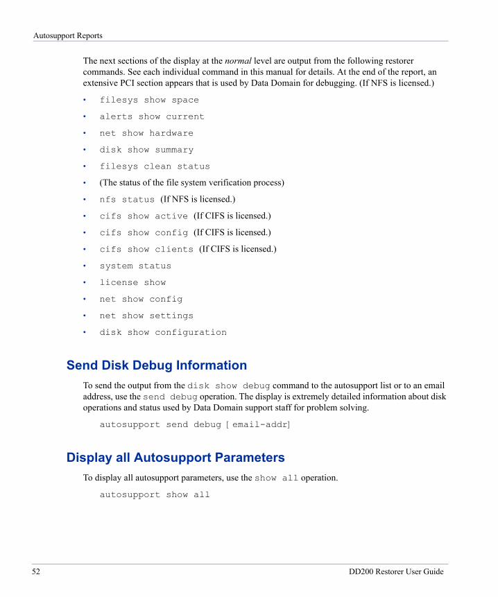
Autosupport Reports
The next sections of the display at the normal level are output from the following restorer commands. See each individual command in this manual for details. At the end of the report, an extensive PCI section appears that is used by Data Domain for debugging. (If NFS is licensed.)
• filesys show space
• alerts show current
• net show hardware
• disk show summary
• filesys clean status
• (The status of the file system verification process)
• nfs status (If NFS is licensed.)
• cifs show active (If CIFS is licensed.)
• cifs show config (If CIFS is licensed.)
• cifs show clients (If CIFS is licensed.)
• system status
• license show
• net show config
• net show settings
• disk show configuration
Send Disk Debug InformationTo send the output from the disk show debug command to the autosupport list or to an email address, use the send debug operation. The display is extremely detailed information about disk operations and status used by Data Domain support staff for problem solving.
autosupport send debug [email-addr]
Display all Autosupport ParametersTo display all autosupport parameters, use the show all operation.
autosupport show all
52 DD200 Restorer User Guide
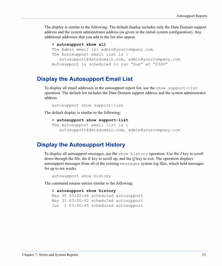
Autosupport Reports
The display is similar to the following. The default display includes only the Data Domain support address and the system administrator address (as given in the initial system configuration). Any additional addresses that you add to the list also appear.
# autosupport show all The Admin email is: [email protected] The Autosupport email list is :
[email protected], [email protected] Autosupport is scheduled to run “Sun” at “0300”
Display the Autosupport Email ListTo display all email addresses in the autosupport report list, use the show support-list operation. The default list includes the Data Domain support address and the system administrator address.
autosupport show support-list
The default display is similar to the following:
# autosupport show support-list The Autosupport email list is :
[email protected], [email protected]
Display the Autosupport HistoryTo display all autosupport messages, use the show history operation. Use the J key to scroll down through the file, the K key to scroll up, and the Q key to exit. The operation displays autosupport messages from all of the existing messages system log files, which hold messages for up to ten weeks.
autosupport show history
The command returns entries similar to the following:
# autosupport show history May 30 03:00:46 scheduled autosupport May 31 03:00:42 scheduled autosupport Jun 1 03:00:45 scheduled autosupport
Chapter 7: Alerts and System Reports 53
Hourly System Status
Display the Autosupport Report ScheduleDisplay the date and time when the autosupport report runs with the show schedule operation.
autosupport show schedule
The display is similar to the following:
# autosupport show schedule Autosupport is scheduled to run “Sun” at “0300”
Hourly System StatusThe restorer automatically generates a brief system status message every hour. The message is sent to the system log and to a serial console if one is attached. To see the hourly message, use the log view command. The message reports system uptime, the amount of data stored, the number of NFS operations, and the amount of disk space used for data storage (as a percentage). For example:
# log view Jun 27 13:00:00 localhost logger: at 1:00pm up 3 days, 3:42, 52324 NFS ops, 84763 GB data
col. (1%) Jun 27 14:00:00 localhost logger: at 2:00pm up 3 days, 4:42, 59411 NFS ops, 84840 GB data
col. (1%)
54 DD200 Restorer User Guide
File System Management
8
The filesys command allows you to display statistics, capacity, status, and utilization of the restorer file system. The command also allows you to clear the statistics file and to start and stop the file system processes. See “filesys” on page 191 for the complete command syntax.The clean operations of the filesys command reclaim physical storage within the restorer file system.Statistics and Basic OperationsThe following operations manage file system statistics and status displays and start and stop file system processes.
Start the Restorer File System ProcessTo start the restorer file system, allowing restorer operations to begin, use the enable operation. Administrative users only.
filesys enable
Stop the Restorer File System ProcessTo stop the restorer file system, which stops restorer operations, use the disable operation. The operation is available to administrative users only.
filesys disable
Delete All Data in the File SystemTo delete all data in the restorer file system and re-initialize the file system, use the destroy operation. Deleted data is not recoverable. The and-zero option writes zeros to all disks, which can take many hours. Administrative users only.
filesys destroy [and-zero]
55
Statistics and Basic Operations
The display includes a warning similar to the following:
# filesys destroy This command irrevocably destroys all data in the ‘/backup’ data collection and creates a newly initialized (empty) file system. The ‘filesys destroy’ operation will take about 15 minutes. File access is disabled during this process.
Are you sure? (yes|no|?) [no]:
Display File System StatusTo display the state of the file system process, use the status operation. The display gives a basic status of enabled or disabled with more detailed information for each basic status. If the clean process is running, the status of that process is included.
filesys status
The display is similar to the following:
# filesys status The filesystem is enabled and running
If the file system was shut down with a restorer command, such as filesys disable, the display includes the command. For example:
# filesys status The filesystem is disabled and shutdown. [filesys disable]
Display File System UptimeTo display the amount of time that has passed since the file system was last enabled, use the show uptime operation. The display is in days and hours and minutes.
filesys show uptime
The display is similar to the following:
# filesys show uptime Filesys has been up 47 days, 23:28
Display File System Space UtilizationTo display the space used by and available to file system components, use the show space operation. Values are in gigabytes to one decimal place.
filesys show space
56 DD200 Restorer User Guide
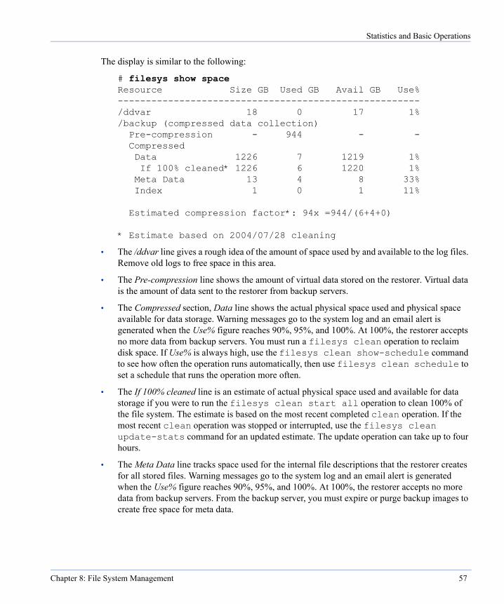
Statistics and Basic Operations
The display is similar to the following:
# filesys show space Resource Size GB Used GB Avail GB Use% ------------------------------------------------------ /ddvar 18 0 17 1% /backup (compressed data collection) Pre-compression - 944 - - Compressed Data 1226 7 1219 1% If 100% cleaned* 1226 6 1220 1% Meta Data 13 4 8 33% Index 1 0 1 11% Estimated compression factor*: 94x =944/(6+4+0) * Estimate based on 2004/07/28 cleaning
• The /ddvar line gives a rough idea of the amount of space used by and available to the log files. Remove old logs to free space in this area.
• The Pre-compression line shows the amount of virtual data stored on the restorer. Virtual data is the amount of data sent to the restorer from backup servers.
• The Compressed section, Data line shows the actual physical space used and physical space available for data storage. Warning messages go to the system log and an email alert is generated when the Use% figure reaches 90%, 95%, and 100%. At 100%, the restorer accepts no more data from backup servers. You must run a filesys clean operation to reclaim disk space. If Use% is always high, use the filesys clean show-schedule command to see how often the operation runs automatically, then use filesys clean schedule to set a schedule that runs the operation more often.
• The If 100% cleaned line is an estimate of actual physical space used and available for data storage if you were to run the filesys clean start all operation to clean 100% of the file system. The estimate is based on the most recent completed clean operation. If the most recent clean operation was stopped or interrupted, use the filesys clean update-stats command for an updated estimate. The update operation can take up to four hours.
• The Meta Data line tracks space used for the internal file descriptions that the restorer creates for all stored files. Warning messages go to the system log and an email alert is generated when the Use% figure reaches 90%, 95%, and 100%. At 100%, the restorer accepts no more data from backup servers. From the backup server, you must expire or purge backup images to create free space for meta data.
Chapter 8: File System Management 57
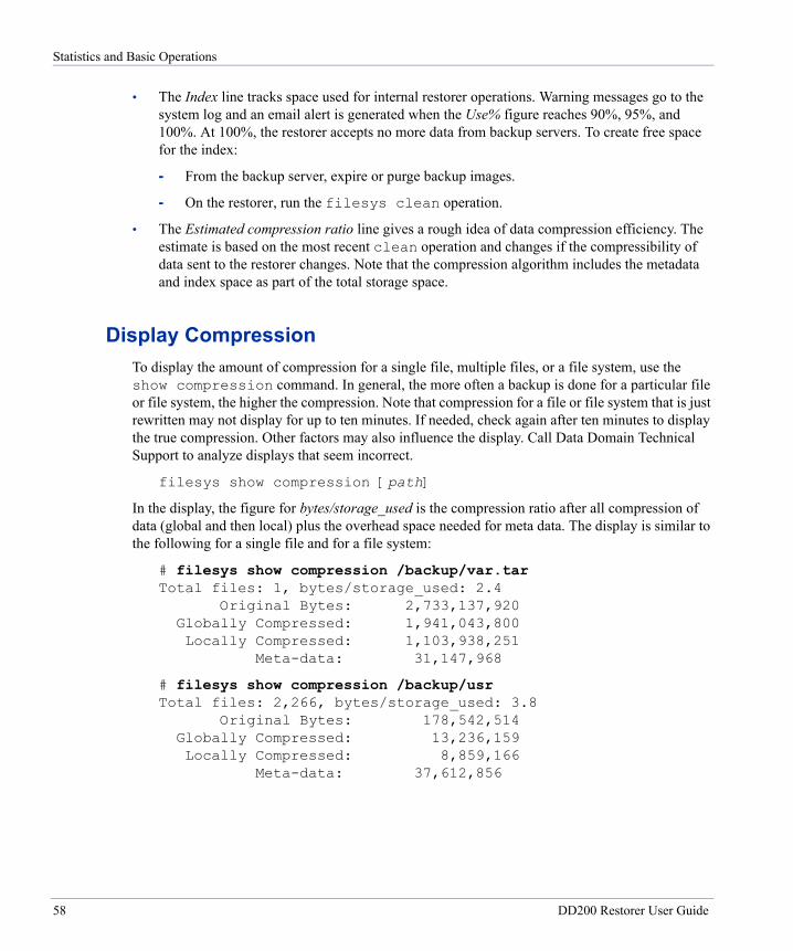
Statistics and Basic Operations
• The Index line tracks space used for internal restorer operations. Warning messages go to the system log and an email alert is generated when the Use% figure reaches 90%, 95%, and 100%. At 100%, the restorer accepts no more data from backup servers. To create free space for the index:
- From the backup server, expire or purge backup images.
- On the restorer, run the filesys clean operation.
• The Estimated compression ratio line gives a rough idea of data compression efficiency. The estimate is based on the most recent clean operation and changes if the compressibility of data sent to the restorer changes. Note that the compression algorithm includes the metadata and index space as part of the total storage space.
Display CompressionTo display the amount of compression for a single file, multiple files, or a file system, use the show compression command. In general, the more often a backup is done for a particular file or file system, the higher the compression. Note that compression for a file or file system that is just rewritten may not display for up to ten minutes. If needed, check again after ten minutes to display the true compression. Other factors may also influence the display. Call Data Domain Technical Support to analyze displays that seem incorrect.
filesys show compression [path]
In the display, the figure for bytes/storage_used is the compression ratio after all compression of data (global and then local) plus the overhead space needed for meta data. The display is similar to the following for a single file and for a file system:
# filesys show compression /backup/var.tar Total files: 1, bytes/storage_used: 2.4 Original Bytes: 2,733,137,920 Globally Compressed: 1,941,043,800 Locally Compressed: 1,103,938,251 Meta-data: 31,147,968
# filesys show compression /backup/usr Total files: 2,266, bytes/storage_used: 3.8 Original Bytes: 178,542,514 Globally Compressed: 13,236,159 Locally Compressed: 8,859,166 Meta-data: 37,612,856
58 DD200 Restorer User Guide
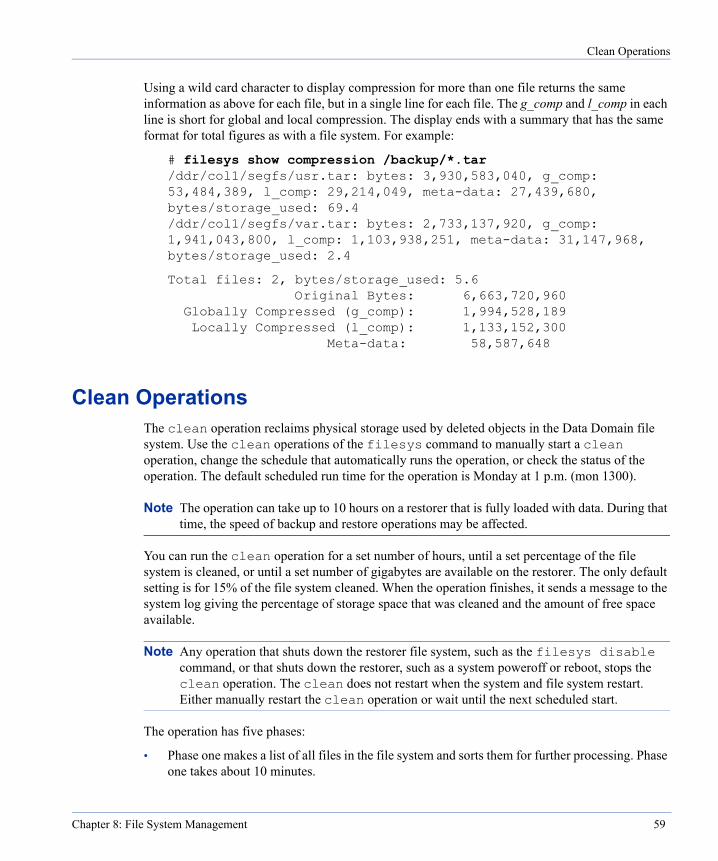
Clean Operations
Using a wild card character to display compression for more than one file returns the same information as above for each file, but in a single line for each file. The g_comp and l_comp in each line is short for global and local compression. The display ends with a summary that has the same format for total figures as with a file system. For example:
# filesys show compression /backup/*.tar /ddr/col1/segfs/usr.tar: bytes: 3,930,583,040, g_comp: 53,484,389, l_comp: 29,214,049, meta-data: 27,439,680, bytes/storage_used: 69.4 /ddr/col1/segfs/var.tar: bytes: 2,733,137,920, g_comp: 1,941,043,800, l_comp: 1,103,938,251, meta-data: 31,147,968, bytes/storage_used: 2.4
Total files: 2, bytes/storage_used: 5.6 Original Bytes: 6,663,720,960 Globally Compressed (g_comp): 1,994,528,189 Locally Compressed (l_comp): 1,133,152,300 Meta-data: 58,587,648
Clean OperationsThe clean operation reclaims physical storage used by deleted objects in the Data Domain file system. Use the clean operations of the filesys command to manually start a clean operation, change the schedule that automatically runs the operation, or check the status of the operation. The default scheduled run time for the operation is Monday at 1 p.m. (mon 1300).
Note The operation can take up to 10 hours on a restorer that is fully loaded with data. During that time, the speed of backup and restore operations may be affected.
You can run the clean operation for a set number of hours, until a set percentage of the file system is cleaned, or until a set number of gigabytes are available on the restorer. The only default setting is for 15% of the file system cleaned. When the operation finishes, it sends a message to the system log giving the percentage of storage space that was cleaned and the amount of free space available.
Note Any operation that shuts down the restorer file system, such as the filesys disable command, or that shuts down the restorer, such as a system poweroff or reboot, stops the clean operation. The clean does not restart when the system and file system restart. Either manually restart the clean operation or wait until the next scheduled start.
The operation has five phases:
• Phase one makes a list of all files in the file system and sorts them for further processing. Phase one takes about 10 minutes.
Chapter 8: File System Management 59
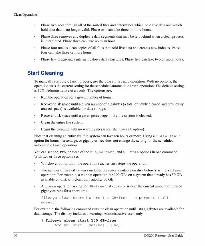
Clean Operations
• Phase two goes through all of the sorted files and determines which hold live data and which hold data that is no longer valid. Phase two can take three or more hours.
• Phase three removes any duplicate data segments that may be left behind when a clean process is interrupted. Phase three can take up to an hour.
• Phase four makes clean copies of all files that hold live data and creates new indexes. Phase four can take three or more hours.
• Phase five regenerates internal restorer data structures. Phase five can take two or more hours.
Start CleaningTo manually start the clean process, use the clean start operation. With no options, the operation uses the current setting for the scheduled automatic clean operation. The default setting is 15%. Administrative users only. The options are:
• Run the operation for a given number of hours.
• Recover disk space until a given number of gigabytes (a total of newly cleaned and previously unused space) is available for data storage.
• Recover disk space until a given percentage of the file system is cleaned.
• Clean the entire file system.
• Begin the cleaning with no warning messages (the nowait option).
Note that cleaning an entire full file system can take ten hours or more. Using a clean start option for hours, percentage, or gigabytes free does not change the setting for the scheduled automatic clean operation.
You can set one, two, or three of the hrs, percent, and GB-free options in one command. With two or three options set:
• Whichever option limit the operation reaches first stops the operation.
• The number of free GB always includes the space available on disk before starting a clean operation. For example, a clean operation for 100 GBs on a system that already has 50 GB available on disk will clean only another 50 GB.
• A clean operation asking for GB-free that equals or is near the current amount of unused gigabytes runs for a short time.
filesys clean start [n hrs | n GB-free | n percent | all | nowait]
For example, the following command runs the clean operation until 100 gigabytes are available for data storage. The display includes a warning. Administrative users only.
# filesys clean start 100 GB-free Are you sure? (yes|no|?) [no]:
60 DD200 Restorer User Guide
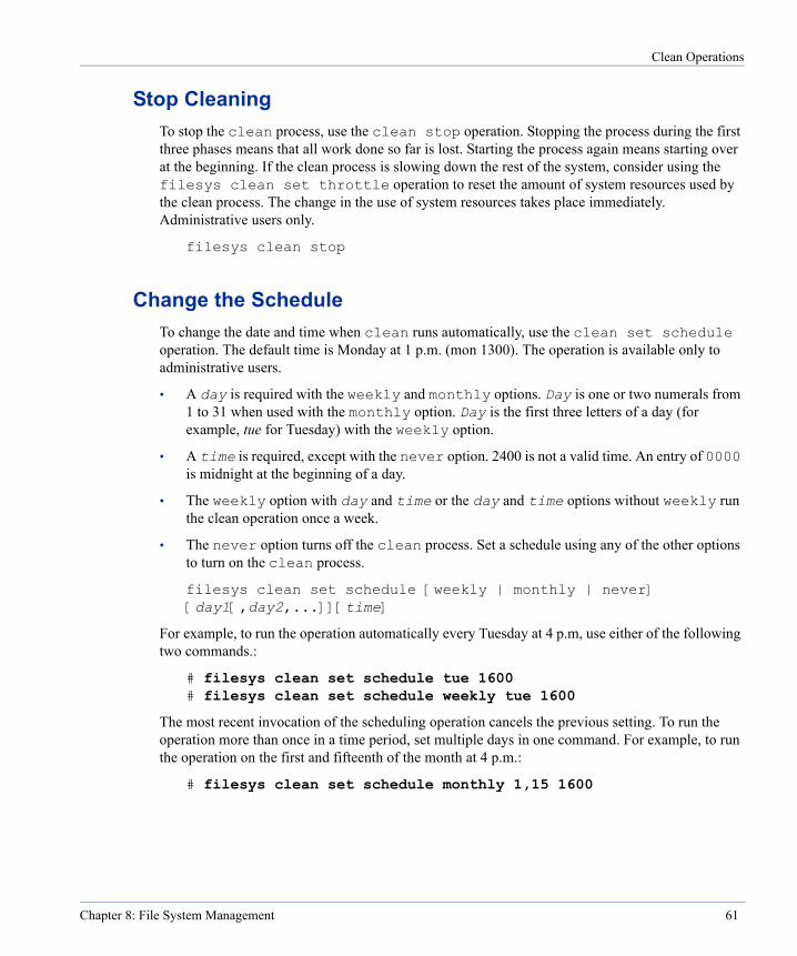
Clean Operations
Stop CleaningTo stop the clean process, use the clean stop operation. Stopping the process during the first three phases means that all work done so far is lost. Starting the process again means starting over at the beginning. If the clean process is slowing down the rest of the system, consider using the filesys clean set throttle operation to reset the amount of system resources used by the clean process. The change in the use of system resources takes place immediately. Administrative users only.
filesys clean stop
Change the ScheduleTo change the date and time when clean runs automatically, use the clean set schedule operation. The default time is Monday at 1 p.m. (mon 1300). The operation is available only to administrative users.
• A day is required with the weekly and monthly options. Day is one or two numerals from 1 to 31 when used with the monthly option. Day is the first three letters of a day (for example, tue for Tuesday) with the weekly option.
• A time is required, except with the never option. 2400 is not a valid time. An entry of 0000 is midnight at the beginning of a day.
• The weekly option with day and time or the day and time options without weekly run the clean operation once a week.
• The never option turns off the clean process. Set a schedule using any of the other options to turn on the clean process.
filesys clean set schedule [weekly | monthly | never] [day1[,day2,...]][time]
For example, to run the operation automatically every Tuesday at 4 p.m, use either of the following two commands.:
# filesys clean set schedule tue 1600 # filesys clean set schedule weekly tue 1600
The most recent invocation of the scheduling operation cancels the previous setting. To run the operation more than once in a time period, set multiple days in one command. For example, to run the operation on the first and fifteenth of the month at 4 p.m.:
# filesys clean set schedule monthly 1,15 1600
Chapter 8: File System Management 61
Clean Operations
Set the Schedule or Amount to the DefaultTo set the clean schedule to the default of Monday at 1 p.m. (mon 1300), or the default amount or throttle of 15%, or to reset all clean parameters, use the clean reset operation. The operation is available only to administrative users.
filesys clean reset {amount | schedule | throttle | all}
Set the Run Time, Gigabytes, or Percent CleanedTo set the scheduled clean operation to run for a given time, until a given percentage of the stored data is cleaned, until a given number of gigabytes are available for data storage, or until the entire file system is cleaned, use the clean set amount operation. By default, the scheduled clean operation cleans 15% of data in the file system. Note that cleaning an entire full file system can take longer than ten hours. Administrative users only.
Data Domain recommends setting a percentage instead of a number of hours. With a percentage, scripts that start cleaning do not need changing when the amount of data in the file system increases. Setting hours to the amount displayed as recommended time for cleaning now with the filesys clean show recommended command returns a warning that when the file system is full, the time needed for cleaning increases.
You can set the hrs, percent, and GB-free options in one command. With two or three options set, whichever limit the operation reaches first stops the operation.
filesys clean set amount {[[n hrs][n GB-free][n percent]] | all}
For example, to set the clean operation to run until 100 gigabytes are available for data:
# filesys clean set amount 100 GB-free
Set System Resources UsedTo set clean operations to use a given level of system resources when the restorer is busy, use the set throttle operation. At a percentage of 0 (zero), cleaning runs very slowly or not at all when the system is busy. A percentage of 100 allows cleaning to take as much in the way of system resources as needed, even when the system is busy. The default is 100. When the restorer is not busy with backup or restore operations, cleaning runs at 100%. Administrative users only.
filesys clean set throttle percent
For example, to set the clean operation to run at 30% of its possible speed:
# filesys clean set throttle 30
62 DD200 Restorer User Guide
Clean Operations
Update StatisticsTo update the “If 100% cleaned” numbers that show in the output from filesys show space, use the clean update-stats operation. During the update, the speed of backup and restore operations may be affected. With a full file system, the update operation can take up to four hours. Administrative users only.
filesys clean update-stats
Display the ScheduleTo display the current date and time for the clean operation, use clean show schedule.
filesys clean show schedule
The display is similar to the following.:
# filesys clean show schedule Filesystem cleaning is scheduled to run “Mon” at “1300”
Display the Amount ParametersTo display the hours and GB settings for the clean operation, use the clean show amount operation.
filesys clean show amount
The display is similar to the following.:
# filesys clean show amount The current cleaning settings are:
6 Hours 0 GBs (unlimited)
Display the Throttle SettingTo display the throttle setting for cleaning operations, use the clean show throttle operation.
filesys clean show throttle
The display is similar to the following.:
# filesys clean show throttle Current cleaning throttle = 50
Chapter 8: File System Management 63
Clean Operations
Display the Clean Operation StatusTo display the active/inactive status of the clean operation, use the clean status operation. When the clean operation is running, the command displays progress.
filesys clean status
The display is similar to the following.:
# filesys clean status Cleaning is active. cleaning progress: phase 1 of 5
Display Recommended Cleaning TimesTo display system estimates of time needed for cleaning, use the clean show recommended operation. The display shows time estimates for running the filesys clean update-stats and filesys clean start all commands, and gives recommended times for cleaning the amount of data that is currently in the file system and for cleaning a full file system. For example:
# filesys clean show recommended Estimated and recommended cleaning times.
estimated time to update-stats only: 2hrs 26min estimated time to ‘clean all’: 6hrs 42 min recommended time for cleaning now: 3hrs recommended time for completely full system: >=10hrs
64 DD200 Restorer User Guide
Disk Management
9
The restorer disk command manages disks and displays disk locations, logical (RAID) layout, usage, and reliability statistics. See “disk” on page 189 for the complete command syntax.Each disk has two LEDs that are visible through the cutouts in the restorer front panel. The LED on the right glows a steady green when the disk has power and is functioning normally. The same LED glows a steady red if the disk has failed, or flashes green when the disk is a target of the beacon operation. The LED on the left flashes green whenever the disk is accessed.
Fail a DiskTo set a disk to the failed state, use the fail disk-ID operation. To physically remove a failed disk, see “Replace Disks” on page 138. A failed disk is removed from RAID mirroring and is replaced by a spare disk (when a spare is available). See “Display RAID Status for Disks” on page 69 to list available spares. The disk fail disk-ID command asks for a confirmation before carrying out the operation. Available to administrative users only.
disk fail disk-ID
If a disk is the only disk left in its mirror, the disk cannot be failed. To match a disk with the other half of its mirror, use the disk show logical-layout command. For example, disk0 may have the tag md20. The disk that is the other half of the mirror has the same tag, md20. In the example shown in the section “Display the RAID Use of Disks” on page 67, the other half of the disk1 md20 mirror is disk9.
When a spare disk is available, the restorer file system automatically replaces a failed disk with a spare and begins the reconstruction process to integrate the spare into the RAID mirror. The disk use changes from spare to in use and the status becomes reconstructing.
Note The system BIOS boots from disk 16. If disk 16 is failed or was replaced with a disk that does not have a valid boot block, the system cannot boot. All disks in the system have a valid boot block unless they are failed or damaged. Be sure that a bootable disk is in slot 16 when rebooting the system.
65
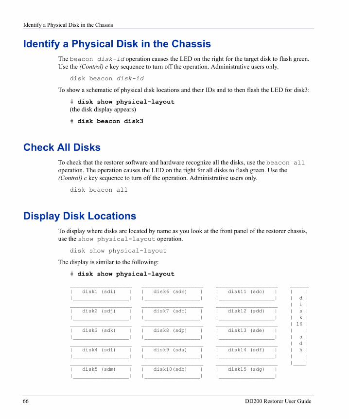
Identify a Physical Disk in the Chassis
Identify a Physical Disk in the ChassisThe beacon disk-id operation causes the LED on the right for the target disk to flash green. Use the (Control) c key sequence to turn off the operation. Administrative users only.
disk beacon disk-id
To show a schematic of physical disk locations and their IDs and to then flash the LED for disk3:
# disk show physical-layout (the disk display appears)
# disk beacon disk3
Check All DisksTo check that the restorer software and hardware recognize all the disks, use the beacon all operation. The operation causes the LED on the right for all disks to flash green. Use the (Control) c key sequence to turn off the operation. Administrative users only.
disk beacon all
Display Disk LocationsTo display where disks are located by name as you look at the front panel of the restorer chassis, use the show physical-layout operation.
disk show physical-layout
The display is similar to the following:
# disk show physical-layout
____________________ ____________________ ____________________ ______| disk1 (sdi) | | disk6 (sdn) | | disk11 (sdc) | | ||__________________| |__________________| |__________________| | d |____________________ ____________________ ____________________ | i || disk2 (sdj) | | disk7 (sdo) | | disk12 (sdd) | | s ||__________________| |__________________| |__________________| | k |____________________ ____________________ ____________________ | 16 || disk3 (sdk) | | disk8 (sdp) | | disk13 (sde) | | ||__________________| |__________________| |__________________| | s |____________________ ____________________ ____________________ | d || disk4 (sdl) | | disk9 (sda) | | disk14 (sdf) | | h ||__________________| |__________________| |__________________| | |____________________ ____________________ ____________________ |____|| disk5 (sdm) | | disk10(sdb) | | disk15 (sdg) | |__________________| |__________________| |__________________|
66 DD200 Restorer User Guide
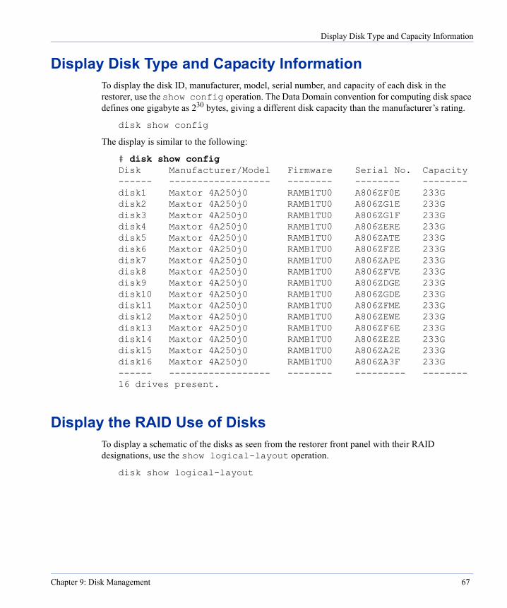
Display Disk Type and Capacity Information
Display Disk Type and Capacity InformationTo display the disk ID, manufacturer, model, serial number, and capacity of each disk in the restorer, use the show config operation. The Data Domain convention for computing disk space defines one gigabyte as 230 bytes, giving a different disk capacity than the manufacturer’s rating.
disk show config
The display is similar to the following:
# disk show config Disk Manufacturer/Model Firmware Serial No. Capacity ------ ------------------ -------- -------- -------- disk1 Maxtor 4A250j0 RAMB1TU0 A806ZF0E 233G disk2 Maxtor 4A250j0 RAMB1TU0 A806ZG1E 233G disk3 Maxtor 4A250j0 RAMB1TU0 A806ZG1F 233G disk4 Maxtor 4A250j0 RAMB1TU0 A806ZERE 233G disk5 Maxtor 4A250j0 RAMB1TU0 A806ZATE 233G disk6 Maxtor 4A250j0 RAMB1TU0 A806ZFZE 233G disk7 Maxtor 4A250j0 RAMB1TU0 A806ZAPE 233G disk8 Maxtor 4A250j0 RAMB1TU0 A806ZFVE 233G disk9 Maxtor 4A250j0 RAMB1TU0 A806ZDGE 233G disk10 Maxtor 4A250j0 RAMB1TU0 A806ZGDE 233G disk11 Maxtor 4A250j0 RAMB1TU0 A806ZFME 233G disk12 Maxtor 4A250j0 RAMB1TU0 A806ZEWE 233G disk13 Maxtor 4A250j0 RAMB1TU0 A806ZF6E 233G disk14 Maxtor 4A250j0 RAMB1TU0 A806ZEZE 233G disk15 Maxtor 4A250j0 RAMB1TU0 A806ZA2E 233G disk16 Maxtor 4A250j0 RAMB1TU0 A806ZA3F 233G ------ ------------------ -------- --------- -------- 16 drives present.
Display the RAID Use of DisksTo display a schematic of the disks as seen from the restorer front panel with their RAID designations, use the show logical-layout operation.
disk show logical-layout
Chapter 9: Disk Management 67
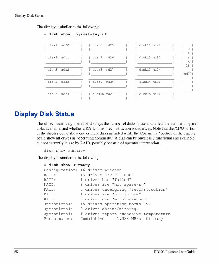
Display Disk Status
The display is similar to the following:
# disk show logical-layout
____________________ ____________________ ____________________ ______| disk1 md20 | | disk6 md25 | | disk11 md22 | | ||__________________| |__________________| |__________________| | d |____________________ ____________________ ____________________ | i || disk2 md21 | | disk7 md26 | | disk12 md23 | | s ||__________________| |__________________| |__________________| | k |____________________ ____________________ ____________________ | 16 || disk3 md22 | | disk8 md27 | | disk13 md24 | | ||__________________| |__________________| |__________________| |md27|____________________ ____________________ ____________________ | || disk4 md23 | | disk9 md20 | | disk14 md25 | | ||__________________| |__________________| |__________________| | |____________________ ____________________ ____________________ |____|| disk5 md24 | | disk10 md21 | | disk15 md26 | |__________________| |__________________| |__________________|
Display Disk StatusThe show summary operation displays the number of disks in use and failed, the number of spare disks available, and whether a RAID mirror reconstruction is underway. Note that the RAID portion of the display could show one or more disks as failed while the Operational portion of the display could show all drives as “operating nominally.” A disk can be physically functional and available, but not currently in use by RAID, possibly because of operator intervention.
disk show summary
The display is similar to the following:
# disk show summary Configuration: 16 drives present RAID: 13 drives are “in use” RAID: 1 drives has "failed" RAID: 2 drives are “hot spare(s)” RAID: 0 drives undergoing “reconstruction” RAID: 1 drives are “not in use” RAID: 0 drives are “missing/absent” Operational: 15 drives operating normally. Operational: 0 drives absent/missing. Operational: 1 drives report excessive temperature Performance: Cumulative 1.338 MB/s, 0% busy
68 DD200 Restorer User Guide
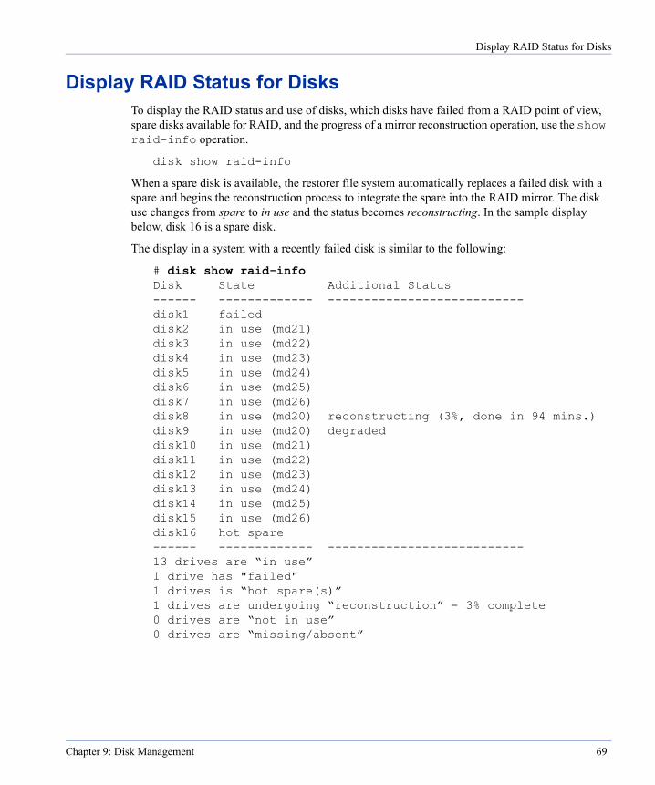
Display RAID Status for Disks
Display RAID Status for DisksTo display the RAID status and use of disks, which disks have failed from a RAID point of view, spare disks available for RAID, and the progress of a mirror reconstruction operation, use the show raid-info operation.
disk show raid-info
When a spare disk is available, the restorer file system automatically replaces a failed disk with a spare and begins the reconstruction process to integrate the spare into the RAID mirror. The disk use changes from spare to in use and the status becomes reconstructing. In the sample display below, disk 16 is a spare disk.
The display in a system with a recently failed disk is similar to the following:
# disk show raid-info Disk State Additional Status ------ ------------- --------------------------- disk1 failed disk2 in use (md21) disk3 in use (md22) disk4 in use (md23) disk5 in use (md24) disk6 in use (md25) disk7 in use (md26) disk8 in use (md20) reconstructing (3%, done in 94 mins.) disk9 in use (md20) degraded disk10 in use (md21) disk11 in use (md22) disk12 in use (md23) disk13 in use (md24) disk14 in use (md25) disk15 in use (md26) disk16 hot spare ------ ------------- --------------------------- 13 drives are “in use” 1 drive has "failed" 1 drives is “hot spare(s)” 1 drives are undergoing “reconstruction” - 3% complete 0 drives are “not in use” 0 drives are “missing/absent”
Chapter 9: Disk Management 69
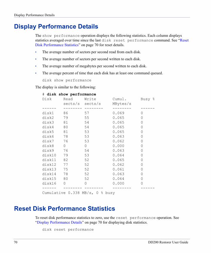
Display Performance Details
Display Performance DetailsThe show performance operation displays the following statistics. Each column displays statistics averaged over time since the last disk reset performance command. See “Reset Disk Performance Statistics” on page 70 for reset details.
• The average number of sectors per second read from each disk.
• The average number of sectors per second written to each disk.
• The average number of megabytes per second written to each disk.
• The average percent of time that each disk has at least one command queued.
disk show performance
The display is similar to the following:
# disk show performance Disk Read Write Cumul. Busy %
sects/s sects/s MBytes/s ------ -------- -------- -------- ------ disk1 86 57 0.069 0 disk2 79 55 0.065 0 disk3 81 54 0.065 0 disk4 80 54 0.065 0 disk5 81 53 0.065 0 disk6 78 53 0.063 0 disk7 76 53 0.062 0 disk8 0 0 0.000 0 disk9 76 54 0.063 0 disk10 79 53 0.064 0 disk11 82 52 0.065 0 disk12 77 52 0.062 0 disk13 75 52 0.061 0 disk14 78 52 0.063 0 disk15 80 52 0.064 0 disk16 0 0 0.000 0 ------ -------- -------- -------- ------ Cumulative 0.338 MB/s, 0 % busy
Reset Disk Performance StatisticsTo reset disk performance statistics to zero, use the reset performance operation. See “Display Performance Details” on page 70 for displaying disk statistics.
disk reset performance
70 DD200 Restorer User Guide
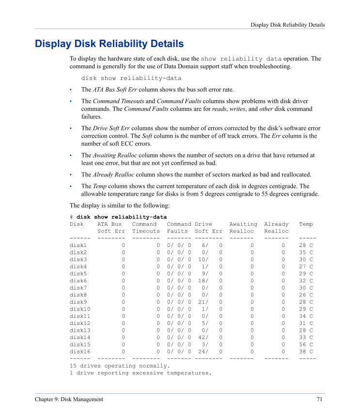
Display Disk Reliability Details
Display Disk Reliability DetailsTo display the hardware state of each disk, use the show reliability data operation. The command is generally for the use of Data Domain support staff when troubleshooting.
disk show reliability-data
• The ATA Bus Soft Err column shows the bus soft error rate.
• The Command Timeouts and Command Faults columns show problems with disk driver commands. The Command Faults columns are for reads, writes, and other disk command failures.
• The Drive Soft Err columns show the number of errors corrected by the disk’s software error correction control. The Soft column is the number of off track errors. The Err column is the number of soft ECC errors.
• The Awaiting Realloc column shows the number of sectors on a drive that have returned at least one error, but that are not yet confirmed as bad.
• The Already Realloc column shows the number of sectors marked as bad and reallocated.
• The Temp column shows the current temperature of each disk in degrees centigrade. The allowable temperature range for disks is from 5 degrees centigrade to 55 degrees centigrade.
The display is similar to the following:
# disk show reliability-data Disk ATA Bus Command Command Drive Awaiting Already Temp Soft Err Timeouts Faults Soft Err Realloc Realloc ------ -------- -------- ------- -------- ------- ------- ----- disk1 0 0 0/ 0/ 0 6/ 0 0 0 28 C disk2 0 0 0/ 0/ 0 0/ 0 0 0 35 C disk3 0 0 0/ 0/ 0 10/ 0 0 0 30 C disk4 0 0 0/ 0/ 0 1/ 0 0 0 27 C disk5 0 0 0/ 0/ 0 9/ 0 0 0 29 C disk6 0 0 0/ 0/ 0 18/ 0 0 0 32 C disk7 0 0 0/ 0/ 0 0/ 0 0 0 30 C disk8 0 0 0/ 0/ 0 0/ 0 0 0 26 C disk9 0 0 0/ 0/ 0 21/ 0 0 0 28 C disk10 0 0 0/ 0/ 0 1/ 0 0 0 29 C disk11 0 0 0/ 0/ 0 0/ 0 0 0 34 C disk12 0 0 0/ 0/ 0 5/ 0 0 0 31 C disk13 0 0 0/ 0/ 0 0/ 0 0 0 28 C disk14 0 0 0/ 0/ 0 42/ 0 0 0 33 C disk15 0 0 0/ 0/ 0 3/ 0 0 0 56 C disk16 0 0 0/ 0/ 0 24/ 0 0 0 38 C ------ -------- -------- ------- -------- ------- ------- ----- 15 drives operating normally. 1 drive reporting excessive temperatures.
Chapter 9: Disk Management 71
Display Disk Debug Information
Display Disk Debug InformationThe show debug operation displays extremely detailed information about disk operations and status. The to-file option sends command output to /ddr/log/disk-show-debug.out. See “Send Disk Debug Information” on page 52 for sending the output to the autosupport email list or to an individual email address. Administrative users only.
disk show debug [to-file]
72 DD200 Restorer User Guide
System Management
10
The restorer system and alias commands allow you to take system-level actions. Examples for the system command are shutting down or restarting the restorer, displaying system problems and status, and setting the system date and time. See “system” on page 231 for the complete command syntax.The alias command allows users to set up aliases for restorer commands. See “alias” on page 178 for the complete command syntax.
The System CommandThe system command manages system-level actions on the restorer.
Shut down the Restorer HardwareTo shut down power to the restorer, use the poweroff operation. The operation automatically does an orderly shut down of the file system process. The operation is available to administrative users only.
system poweroff
The display includes a warning similar to the following:
# system poweroff The ‘system poweroff’ command shuts down the system and turns off the power.
Continue? (yes|no|?) [no]:
Reboot the RestorerTo have the restorer shutdown and then reboot, use the reboot operation. The operation is available to administrative users only. The operation automatically does an orderly shutdown of the file system process.
system reboot
73

The System Command
The display includes a warning similar to the following:
# system reboot The ‘system reboot’ command reboots the system. File access is interrupted during the reboot.
Are you sure? (yes|no|?) [no]:
Note The system BIOS boots from disk 16. If disk 16 is failed or was replaced with a disk that does not have a valid boot block, the system cannot boot. The first four disks in the system are bootable: disks 16, 11, 12, and 13. Be sure that a bootable disk is in slot 16 when rebooting the system.
Upgrade Restorer SoftwareYou can upgrade restorer software either from the Data Domain Support web site, using FTP, or from a Data Domain CD.
Note The upgrade operation shuts down the restorer file system and reboots the restorer. The upgrade operation may take over an hour, depending on the amount of data on your system. After the upgrade completes and the system reboots, the /backup file system is disabled for up to an hour for upgrade processing.
To upgrade from the Data Domain web site
1. Log in to a restorer administrative host that mounts /ddvar from the restorer.
2. On the administrative host, open a browser and go to the Data Domain Support web site (support.datadomain.com). Use either HTTP or FTP to connect to the web site. For example:
http://support.datadomain.com
3. Log in with the Data Domain login name and password that you use for access to the support web page or FTP site.
Note Some web browsers do not automatically ask for a login if a machine does not accept all logins. In that case, add your user name and password. For example: http://your-name:[email protected]
4. Click on Downloads. (If the web site has updated instructions, follow those instructions.)
5. Click on the Download button for the latest release.
74 DD200 Restorer User Guide
The System Command
6. Download the new release file to the restorer directory /ddvar/releases.
7. To start the upgrade, log in to the restorer as sysadmin and enter a command similar to the following. Use the file name (not a path) received from Data Domain. For example:
# system upgrade 1.0.10.8-9881.rpm
To upgrade from a CD
1. Log in to the restorer as sysadmin.
2. Insert the Data Domain CD into the restorer CD drive.
3. Enter a command similar to the following. Use the file name (with no path) that is on the CD:
# system upgrade 1.0.10.8-9881.rpm
To upgrade using FTP
1. Log in to a restorer administrative host that mounts /ddvar from the restorer.
2. On the administrative host, use FTP to connect to the Data Domain support site:
# ftp://support.datadomain.com
3. Log in with the Data Domain login name and password that you use for access to the support web page.
4. Download the release recommended by your Data Domain field representative. The file should go to /ddvar/releases on the restorer.
5. To start the upgrade, log in to restorer as sysadmin and enter a command similar to the following. Use the file name (not a path) received from Data Domain. For example:
# system upgrade 1.0.10.8-9881.rpm
Change the Mail Server HostnameTo change the SMTP mail server used by the restorer, use the set mailserver host operation. Administrative users only.
system set mailserver host
Chapter 10: System Management 75

The System Command
For example, to set the mail server to mail.yourcompany.com:
# system set mailserver mail.yourcompany.com
To check the operation, use the system show mailserver command.
Change the Administrative Email AddressTo change the administrative email address used by the restorer for messages from the alerts and autosupport utilities, use the set admin-email email-addr operation. The system needs one and only one administrative email address. To add other addresses to the alerts or autosupport email lists, use the alerts and autosupport commands. Administrative users only.
system set admin-email email-addr
For example, to set the administrative address to rjones.yourcompany.com:
# system set admin-email rjones.yourcompany.com
To check the operation, use the system show admin-email command.
Change the Administrative HostTo change the machine from which you can log into the restorer to see system logs and use system commands, use the set admin-host host operation. The host name can be a simple host name, a host name with a fully-qualified domain name, or an IP address. Administrative users only.
system set admin-host host
For example, to set the administrative host to admin12.yourcompany.com:
# system set admin-host admin12.yourcompany.com
To check the operation, use the system show admin-host command.
Change the System Location DescriptionTo change the description of a restorer location, use the set location “location” operation. A description of a physical location helps identify the machine when viewing alerts and autosupport emails. The description must be in double quotes. Administrative users only.
system set location “location”
For example, to set the location description to row2-num4-room221:
# system set location “row2-num4-room221”
To check the operation, use the system show location command.
76 DD200 Restorer User Guide
The System Command
Set the Date and TimeTo set the system date and time, use the set date operation. The entry is two places for month (01 through 12), two places for day of the month (01 through 31), two places for hour (00 through 23), two places for minutes (00 through 59), and optionally, two places for century and two places for year. The hour (hh) and minute (mm) entries are 24-hour military time with no colon between hours and minutes. 2400 is not a valid entry. An entry of 0000 is midnight at the beginning of a day. The operation is available to administrative users only.
system set date MMDDhhmm[[cc]yy]
For example, use either of the following commands to set the date and time to October 22 at 9:24 a.m. in the year 2003:
# system set date 1022092403 # system set date 102209242003
Set a Time Zone for the System ClockTo set the system clock to a specific time zone, use the set timezone operation. The default setting is US/Pacific. See the appendix: “Time Zones” on page 167 for a complete list of time zones. For the change to take effect for all currently running processes, you must reboot the restorer. The operation is available to administrative users only.
system set timezone zone
For example, to set the system clock to the time zone that includes Los Angeles, California, USA:
# system set timezone Los_Angeles
To display time zones, enter a category or a partial zone name. The categories are: Africa, America, Asia, Atlantic, Australia, Brazil, Canada, Chile, Europe, Indian, Mexico, Mideast, Pacific, and US. The following examples show the use of a category and the use of a partial zone name:
# system set timezone us US/Alaska US/Aleutian US/Arizona US/Central US/Eastern US/East-Indiana US/Hawaii US/Indiana-Starke US/Michigan US/Mountain US/Pacific US/Samoa
# system set timezone new Ambiguous timezone name, matching ...
America/New_York Canada/Newfoundland
Chapter 10: System Management 77

The System Command
Reset Location, Mailserver, TimezoneTo set the system location, mail server, or time zone to the default value, use the reset operation. The defaults for location and mail server are null entries. The default for time zone is Universal (GMT). The command requires at least one parameter and accepts multiple parameters. Administrative users only.
system reset {[location][mailserver][timezone]}
Display Hardware StatusTo display the monitored status of restorer hardware, use the show faults operation. A restorer automatically monitors:
• Each disk for standard functionality.
• Each cooling fan for the correct speed.
• Each power supply for the correct voltage output.
• Air temperature across the motherboard.
• Temperature of the CPU chips on the motherboard.
To display the status of disks, see the chapter “Disk Management” on page 65.
The command syntax is:
system show faults
The display is similar to the following:
# system show faults Hardware Fault Summary ----------------------
Disk Failure Summary: No disk failures detected.
Power Supply Voltage Error Summary: No power supply errors detected.
Temperature Extremes Summary: No temperature extremes detected.
Fan Failure Summary: Fan failue: Current RPM is 0, Avg RPM is 4500, Crossbar fan #5
78 DD200 Restorer User Guide
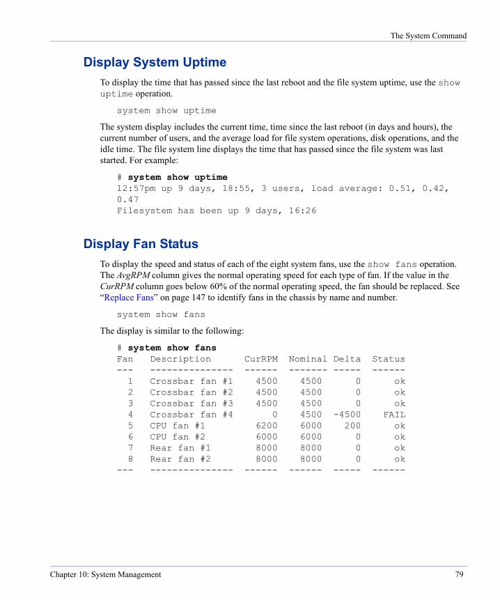
The System Command
Display System UptimeTo display the time that has passed since the last reboot and the file system uptime, use the show uptime operation.
system show uptime
The system display includes the current time, time since the last reboot (in days and hours), the current number of users, and the average load for file system operations, disk operations, and the idle time. The file system line displays the time that has passed since the file system was last started. For example:
# system show uptime 12:57pm up 9 days, 18:55, 3 users, load average: 0.51, 0.42, 0.47 Filesystem has been up 9 days, 16:26
Display Fan StatusTo display the speed and status of each of the eight system fans, use the show fans operation. The AvgRPM column gives the normal operating speed for each type of fan. If the value in the CurRPM column goes below 60% of the normal operating speed, the fan should be replaced. See “Replace Fans” on page 147 to identify fans in the chassis by name and number.
system show fans
The display is similar to the following:
# system show fans Fan Description CurRPM Nominal Delta Status --- --------------- ------ ------- ----- ------ 1 Crossbar fan #1 4500 4500 0 ok 2 Crossbar fan #2 4500 4500 0 ok 3 Crossbar fan #3 4500 4500 0 ok 4 Crossbar fan #4 0 4500 -4500 FAIL 5 CPU fan #1 6200 6000 200 ok 6 CPU fan #2 6000 6000 0 ok 7 Rear fan #1 8000 8000 0 ok 8 Rear fan #2 8000 8000 0 ok --- --------------- ------ ------ ----- ------
Chapter 10: System Management 79
The System Command
Display the System ConfigurationTo display the system’s current configuration, use the show config operation.
system show config
The display includes:
• The current operating system, the type and capacity of the CPUs, and memory size.
• Output from the disk show config command.
• Network interface information and transfer rates.
• PCI information that is useful for Data Domain support staff.
Display Memory UsageTo display how the restorer is using memory, use the show meminfo operation.
system show meminfo
The display is similar to the following:
# system show meminfo Memory Information ------------------
total: used: free: shared: buffers: cached: Mem: 3163451392 1780092928 1383358464 0 23707648 24096768 Swap: 51983556608 0 51983556608 MemTotal: 3090388 kB MemFree: 135096 kB MemShared: 0 kB
Display System StatisticsTo display system statistics for CPUs, disks, Ethernet ports, and NFS, use the show stats operation. The time period covered is from the last reboot, except with interval and count.
An interval, in seconds, runs the command every number of seconds (nsecs) for the number of times in count. The first report covers the time period since the last reboot. Each subsequent report is for activity in the last interval. The default interval is five seconds.
The interval and count labels are optional when giving both an interval and a count. To give only an interval, you can enter a number for nsecs without the interval label. To give only a count, you must enter the count label and a number for count.
80 DD200 Restorer User Guide

The System Command
The start and stop options return averages per second of statistics over the time between the commands.
system show stats [start | stop | ([interval nsecs] [count count])]
The display is similar to the following:
# system show stats 09/30/ 16:23:10 CPU FS FS Net kB/s Disk kB/s Disk busy ops/s proc in out read write busy ---- ----- ---- ---- ---- ----- ----- ----- 9% 624 0 0 0 40834 37245 10% NVRAM kB/s Repl read write kB/s ----- ----- ----
0 0 0
Display Detailed System StatisticsTo display more detailed system statistics, use the show detailed-stats operation. The time period covered is from the last reboot, except when using interval and count.
An interval, in seconds, runs the command every number of seconds (nsecs) for the number of times in count. The first report covers the time period since the last reboot. Each subsequent report is for activity in the last interval. The default interval is five seconds.
The interval and count labels are optional when giving both an interval and a count. To give only an interval, you can enter a number for nsecs without the interval label. To give only a count, you must enter the count label and a number for count.
The start and stop options return averages per second of statistics over the time between the commands.
system show detailed-stats [start | stop | ([interval int][count count])]
The columns in the display are:
CPUx busy The percentage of time that each CPU is busy.
State 'CDVMS' A single character shows whether any of the five following events is occuring. Each event can affect performance.
C cleaning D disk reconstruction (repair of a failed disk)
Chapter 10: System Management 81

The System Command
V verify data (a background process that checks for data consistency) M merging of the internal fingerprint index S summary vector internal checkpoint process
NFS ops/s The number of NFS operations per second.
NFS proc The fraction of time that the file server is busy servicing requests.
NFS recv The proportion of NFS-busy time spent waiting for data on the NFS socket.
NFS send The proportion of NFS-busy time spent sending data out on the socket.
NFS idle The percentage of NFS idle time.
CIFS ops/s The number of CIFS (Common Internet File System) operations per second.
ethx kB/s The amount of data in kilobytes per second passing through each Ethernet connection. One column appears for each Ethernet connection.
Disk kB/s The amount of data in kilobytes per second going to and from all disks in the restorer.
Disk busy The percentage of time that all disks in the restorer are busy.
NVRAM kB/s The amount of data in kilobytes per second going through non-volatile random-access memory from reads and writes.
Repl kB/s The amount of data in kilobytes per second being replicated between one restorer and another.
The display is similar to the following:
# system show detailed-stats CPU0 CPU1 State NFS NFS NFS NFS NFS CIFS busy busy ‘CDVMS’ ops/s proc recv send idle ops/s ---- ---- ------ ----- ---- ---- ---- ---- ------ 0 % 0 % 624 0% 0% 0 0 ------ eth0 kB/s eth1 kB/s eth2 kB/s eth3 kB/s Disk kB/s in out in out in out in out read write ---- ---- ----- ----- ----- ----- ----- ----- ----- ----- 0 0 0 0 0 0 0 0 0 0 Disk NVRAM kB/s Repl kB/s busy read write in out ---- ---- ----- ---- ---- 0 0 0 0 0
82 DD200 Restorer User Guide

The System Command
Display the Restorer Serial NumberTo display the system serial number, use the show serialno operation.
system show serialno
The display is similar to the following:
# system show serialno Serial number: 22BM030026
Display System StatusTo display the current hardware status, such as processor vital signs, internal temperatures, and power supply output, use the status operation.
system status
The display is similar to the following:
# system status NVRAM card
memory size: 1024 MB window size: 16 MB number batteries: 2 errors: 0 PCI, 0 Memory
battery 1: charge = 100% enabled = yes battery 2: charge = 100% enabled = yes
Temperature Measurements: Ambient: 32.22 C (90.00 F)
Voltage Readings: CPU : 1.45 1.8 : 1.79 3.3 : 3.29 5.0 : 4.90
12.0 : 12.50 -12.0 : -11.23
2.5 : 2.49 All power supply modules operating normally.
CPU Speed Check: Speed of CPU0 = 2392.051 Mhz Speed of CPU1 = 2392.048 Mhz Speed of CPU2 = 2392.046 Mhz Speed of CPU3 = 2392.042 Mhz
Chapter 10: System Management 83
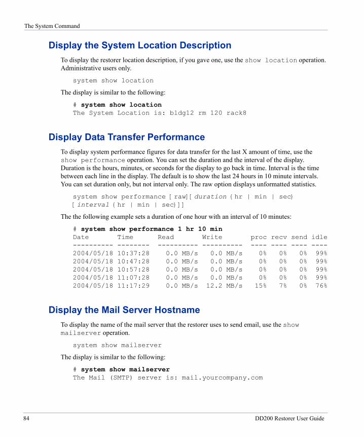
The System Command
Display the System Location DescriptionTo display the restorer location description, if you gave one, use the show location operation. Administrative users only.
system show location
The display is similar to the following:
# system show location The System Location is: bldg12 rm 120 rack8
Display Data Transfer PerformanceTo display system performance figures for data transfer for the last X amount of time, use the show performance operation. You can set the duration and the interval of the display. Duration is the hours, minutes, or seconds for the display to go back in time. Interval is the time between each line in the display. The default is to show the last 24 hours in 10 minute intervals. You can set duration only, but not interval only. The raw option displays unformatted statistics.
system show performance [raw][duration {hr | min | sec} [interval {hr | min | sec}]]
The the following example sets a duration of one hour with an interval of 10 minutes:
# system show performance 1 hr 10 min Date Time Read Write proc recv send idle ---------- -------- ---------- ---------- ---- ---- ---- ---- 2004/05/18 10:37:28 0.0 MB/s 0.0 MB/s 0% 0% 0% 99% 2004/05/18 10:47:28 0.0 MB/s 0.0 MB/s 0% 0% 0% 99% 2004/05/18 10:57:28 0.0 MB/s 0.0 MB/s 0% 0% 0% 99% 2004/05/18 11:07:28 0.0 MB/s 0.0 MB/s 0% 0% 0% 99% 2004/05/18 11:17:29 0.0 MB/s 12.2 MB/s 15% 7% 0% 76%
Display the Mail Server HostnameTo display the name of the mail server that the restorer uses to send email, use the show mailserver operation.
system show mailserver
The display is similar to the following:
# system show mailserver The Mail (SMTP) server is: mail.yourcompany.com
84 DD200 Restorer User Guide

The System Command
Display the Restorer Software VersionTo display the version of software on your system, use the show version operation. The display gives the release number and a build identification number.
system show version
The display is similar to the following:
# system show version Data Domain Restore Protection Manager 2.0.0.0-10112
To display the versions of restorer components on your system, use the show detailed-version operation. The display is useful for Data Domain support staff.
system show detailed-version
The display is similar to the following selected lines:
# system show detailed-version Data Domain Restore Protection Manager 2.0.0.0-10112
//tools/main/devtools/ddr/...@3027 //tools/main/devtools/toolset.bom@2731 //prod/main/os/lib/...@3035 //prod/main/app/...@3281 //prod/main/ddr_dist/ddr_dist_files/...@3203
Display the Administrative Email AddressTo display the administrative email address that the restorer uses for email from the alerts and autosupport utilities, use the show admin-email operation.
system show admin-email
The display is similar to the following:
# system show admin-email The Admin Email is: [email protected]
Display the Administrative Host NameTo display the administrative host from which you can log into the restorer to see system logs and use system commands, use the show admin-host operation.
system show admin-host
The display is similar to the following:
# system show admin-host The Admin Host is: [email protected]
Chapter 10: System Management 85
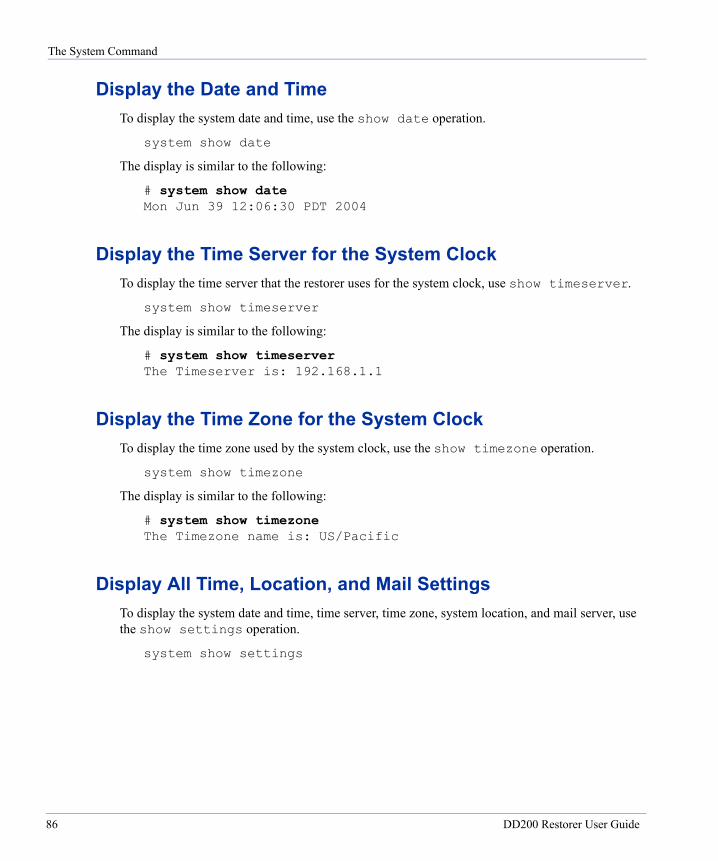
The System Command
Display the Date and TimeTo display the system date and time, use the show date operation.
system show date
The display is similar to the following:
# system show date Mon Jun 39 12:06:30 PDT 2004
Display the Time Server for the System ClockTo display the time server that the restorer uses for the system clock, use show timeserver.
system show timeserver
The display is similar to the following:
# system show timeserver The Timeserver is: 192.168.1.1
Display the Time Zone for the System ClockTo display the time zone used by the system clock, use the show timezone operation.
system show timezone
The display is similar to the following:
# system show timezone The Timezone name is: US/Pacific
Display All Time, Location, and Mail SettingsTo display the system date and time, time server, time zone, system location, and mail server, use the show settings operation.
system show settings
86 DD200 Restorer User Guide

The Alias Command
The display is similar to the following:
# system show settings Tue Jul 29 10:59:48 PDT 2003 The Timeserver is: multicast The Timezone name is: US/Pacific The System Location is: Bldg 24, room 212 The Admin Email is: [email protected] The Admin Host is: [email protected] The Mail (SMTP) server is: mail.yourcompany.com
The Alias CommandThe alias command allows you to add, delete, or display command aliases and their definitions. See “Display Aliases” on page 88 for the list of default aliases.
Add an AliasTo add an alias, use the add name “command” operation. Use double quotes around the command. A new alias is available only to the user who creates the alias. A user can not create a working alias for a command that is outside of that user’s permission level.
alias add name “command”
For example, to add an alias named rely for the restorer command that displays reliability statistics:
# alias add rely “disk show reliability-data”
Remove an AliasTo remove an alias, use the del name operation.
alias del name
For example, to remove an alias named rely:
# alias del rely
Reset AliasesTo return to the default alias list, use the reset operation. Administrative users only.
alias reset
Chapter 10: System Management 87
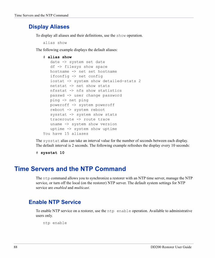
Time Servers and the NTP Command
Display AliasesTo display all aliases and their definitions, use the show operation.
alias show
The following example displays the default aliases:
# alias show date -> system set date df -> filesys show space hostname -> net set hostname ifconfig -> net config iostat -> system show detailed-stats 2 netstat -> net show stats nfsstat -> nfs show statistics passwd -> user change password ping -> net ping poweroff -> system poweroff reboot -> system reboot sysstat -> system show stats traceroute -> route trace uname -> system show version uptime -> system show uptime
You have 15 aliases
The sysstat alias can take an interval value for the number of seconds between each display. The default interval is 2 seconds. The following example refreshes the display every 10 seconds:
# sysstat 10
Time Servers and the NTP CommandThe ntp command allows you to synchronize a restorer with an NTP time server, manage the NTP service, or turn off the local (on the restorer) NTP server. The default system settings for NTP service are enabled and multicast.
Enable NTP ServiceTo enable NTP service on a restorer, use the ntp enable operation. Available to administrative users only.
ntp enable
88 DD200 Restorer User Guide
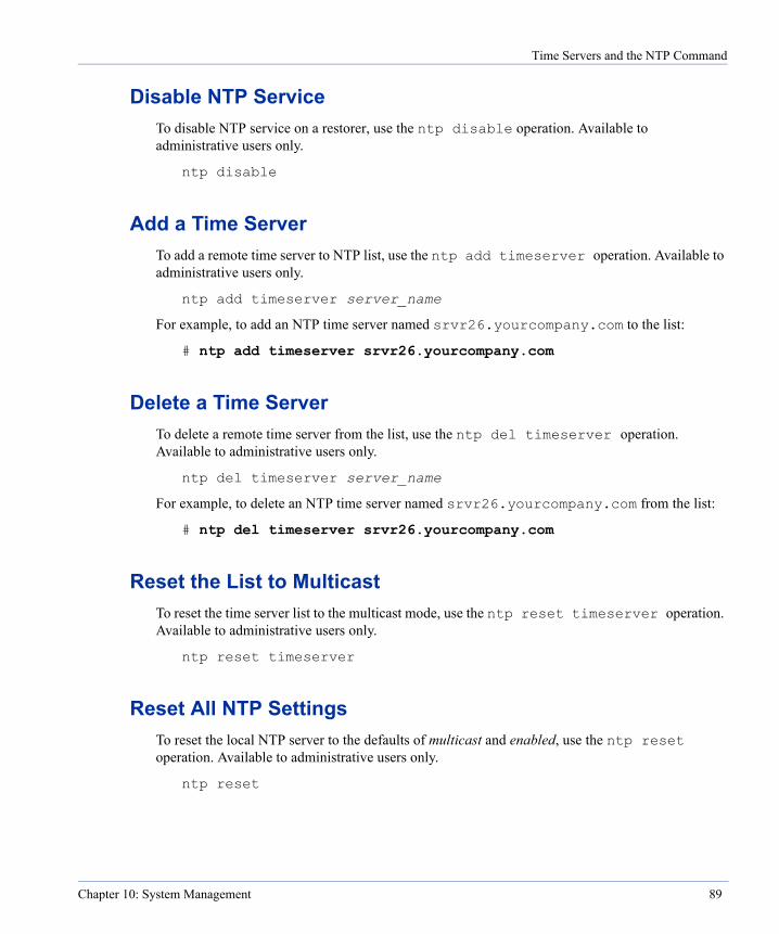
Time Servers and the NTP Command
Disable NTP ServiceTo disable NTP service on a restorer, use the ntp disable operation. Available to administrative users only.
ntp disable
Add a Time ServerTo add a remote time server to NTP list, use the ntp add timeserver operation. Available to administrative users only.
ntp add timeserver server_name
For example, to add an NTP time server named srvr26.yourcompany.com to the list:
# ntp add timeserver srvr26.yourcompany.com
Delete a Time ServerTo delete a remote time server from the list, use the ntp del timeserver operation. Available to administrative users only.
ntp del timeserver server_name
For example, to delete an NTP time server named srvr26.yourcompany.com from the list:
# ntp del timeserver srvr26.yourcompany.com
Reset the List to MulticastTo reset the time server list to the multicast mode, use the ntp reset timeserver operation. Available to administrative users only.
ntp reset timeserver
Reset All NTP SettingsTo reset the local NTP server to the defaults of multicast and enabled, use the ntp reset operation. Available to administrative users only.
ntp reset
Chapter 10: System Management 89
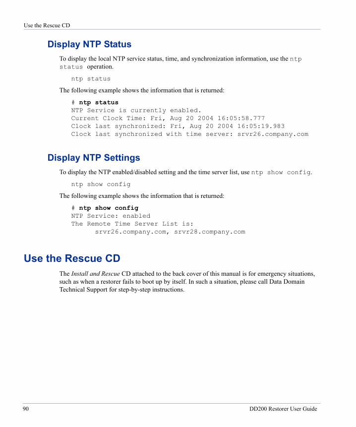
Use the Rescue CD
Display NTP StatusTo display the local NTP service status, time, and synchronization information, use the ntp status operation.
ntp status
The following example shows the information that is returned:
# ntp status NTP Service is currently enabled. Current Clock Time: Fri, Aug 20 2004 16:05:58.777 Clock last synchronized: Fri, Aug 20 2004 16:05:19.983 Clock last synchronized with time server: srvr26.company.com
Display NTP SettingsTo display the NTP enabled/disabled setting and the time server list, use ntp show config.
ntp show config
The following example shows the information that is returned:
# ntp show config NTP Service: enabled The Remote Time Server List is:
srvr26.company.com, srvr28.company.com
Use the Rescue CDThe Install and Rescue CD attached to the back cover of this manual is for emergency situations, such as when a restorer fails to boot up by itself. In such a situation, please call Data Domain Technical Support for step-by-step instructions.
90 DD200 Restorer User Guide
Network Management
11
The net command manages the use of DHCP, DNS, and IP addresses, and displays network information and status. See “net” on page 206 for the complete command syntax.The route command manages routing rules. See “net” on page 206 for the complete command syntax.The Net CommandUse the net command for the following operations.
Enable an InterfaceTo enable a disabled Ethernet interface on the restorer, use the enable interface operation. Administrative users only.
net enable interface
For example, to enable the interface eth0:
# net enable eth0
Disable an InterfaceTo disable an Ethernet interface on the restorer, use the disable interface operation. Administrative users only.
net disable interface
For example, to disable the interface eth0:
# net disable eth0
91
The Net Command
Enable DHCPTo set up an Ethernet interface to expect DHCP information, use the config interface dhcp yes operation. Changes take effect only after a system reboot. Administrative users only.
Note To activate DHCP for an interface when no other interface is using DHCP, the restorer must be rebooted.
net config interface dhcp yes
For example, to set DHCP for the interface eth0:
# net config eth0 dhcp yes
To check the operation, use the net show configuration command. To check that the Ethernet connection is live, use the net show hardware command.
Disable DHCPTo set an Ethernet interface to not use DHCP, use the config interface dhcp no operation. After the operation, you must set an IP address for the interface. All other DHCP settings for the interface are retained. Administrative users only.
net config interface dhcp no
For example, to disable DHCP for the interface eth0:
# net config eth0 dhcp no
To check the operation, use the net show configuration command.
Change an Interface Transfer Unit SizeTo change the maximum transfer unit size for an Ethernet interface, use the config interface mtu operation. Supported values are from 256 to 9180. For 100 Base-T networks, 1500 is standard. For gigabit networks, 9180 is standard. The default is 1500. The default option returns the setting to the default value. Administrative users only.
net config interface mtu {size | default}
For example, to set a maximum transfer unit size of 9180 for the interface eth2:
# net config eth2 mtu 9180
92 DD200 Restorer User Guide
The Net Command
Change an Interface NetmaskTo change the netmask used by an Ethernet interface, use the config interface netmask mask operation. Administrative users only.
net config interface netmask mask
For example, to set the netmask 255.255.255.0 for the interface eth0:
# net config eth0 netmask 255.255.255.0
Add or Change DNS serversTo add or change DNS servers for the restorer to use in resolving addresses, use the set dns ipaddr operation to give DNS server IP addresses. The operation writes over the current list of DNS servers. Only the servers given in the latest command are available to a restorer. The list can be comma-separated, space-separated, or both. Changes take effect only after a system reboot. Administrative users only.
Note To activate a DNS change, the restorer must be rebooted.
net set dns ipaddr1[,ipaddr2[,ipaddr3]]
For example, to allow a restorer to use a DNS server with an IP address of 123.234.78.92:
# net set dns 123.234.78.92
To check the operation, use the net ping host-name command.
Ping a HostTo check that a restorer can communicate with a remote host, use the ping operation with a hostname or IP address.
net ping hostname
For example, to check that communication is possible with the host srvr24:
# net ping srvr24
Change the Restorer HostnameTo change the name other systems use to access the restorer, use the set hostname host operation. Administrative users only.
net set hostname host
Chapter 11: Network Management 93
The Net Command
For example, to set the restorer name to dd10:
# net set hostname dd10
To check the operation, use the net show hostname command.
Change an Interface IP AddressTo change the IP address used by a restorer Ethernet interface, use the config interface ipaddr operation. If the interface is configured for DHCP, the command returns an error. Use the net config interface dhcp disable command to turn off DHCP for an interface. See “Disable DHCP” on page 92 for details. Administrative users only.
net config interface ipaddr
For example, to set the interface eth0 to the IP address of 192.168.1.1:
# net config eth0 192.168.1.1
Use the net show config command to check the operation.
Change the Domain NameTo change the domain name used by the restorer, use the set domainname dm.name operation. Administrative users only.
net set domainname dm.name
For example, to set the domain name to yourcompany-ny.com:
# net set domainname yourcompany-ny.com
Add a Hostname/IP Address to the /etc/hosts FileTo associate an IP address with a hostname, use the hosts add operation. The hostname is a fully-qualified domain name or a hostname. The entry is added to the /etc/hosts file. Administrative users only.
net hosts add ipaddr {host | “alias host”} ...
For example, to associate both the fully-qualified domain name bkup20.yourcompany.com and the hostname of bkup20 with an IP address of 192.168.3.3:
# net hosts add 192.168.3.3 “bkup20 bkup20.yourcompany.com”
94 DD200 Restorer User Guide
The Net Command
Reset Network ParametersTo reset the hostname, domain name, and DNS parameters to their default values (empty), use the reset operation. The command requires at least one parameter and accepts multiple parameters. Changes take effect only after a system reboot. Administrative users only.
Note To activate the DNS change that results from the command, the restorer must be rebooted.
net reset {[hostname][domainname][dns]}
For example, to reset the system host name and domain name:
# net reset hostname domainname
Set Interface Duplex Line UseTo manually set the line use for an interface to half-duplex or full-duplex, use the config interface duplex operation. Half-duplex is not available for any port set for a speed of 1000 (Gigabit). Administrative users only.
net config interface duplex {full | half}
For example, to set the line use to half-duplex for interface eth1:
# net config eth1 duplex half
Set Interface Line SpeedTo manually set the line speed for an interface to 10 Base-T, 100 Base-T, or 1000 Base-T (Gigabit), use the config interface speed operation. A line speed of 1000 allows only a duplex setting of half. Setting a port to a speed of 1000 and duplex of half leads to unpredictable results. Administrative users only.
net config interface speed {10 | 100 | 1000}
For example, to set the line speed to 100 Base-T for interface eth1:
# net config eth1 speed 100
Set Autonegotiate for an InterfaceTo allow the network interface card to autonegotiate the line speed and duplex setting for an interface, use the config interface autoneg operation. Administrative users only.
net config interface autoneg
Chapter 11: Network Management 95
The Net Command
For example, to set autonegotiation for interface eth1:
# net config eth1 autoneg
Delete a Hostname/IP address from the /etc/hosts FileTo delete a hostname/IP address entry from the /etc/hosts file, use the hosts del operation. Administrative users only.
net hosts del ipaddr
For example, to remove the hosts with an IP address of 192.168.3.3:
# net hosts del 192.168.3.3
Delete all Hostname/IP addresses from the /etc/hosts FileTo delete all hostname/IP address entries from the /etc/hosts file, use the hosts reset operation. Administrative users only.
net hosts reset
Display Hostname/IP addresses from the /etc/hosts FileTo display hostname/IP addresses from the /etc/hosts file, use the hosts show operation. Administrative users only.
net hosts show
The display looks similar to the following:
# net hosts show Hostname Mappings:
192.168.3.3 -> bkup20 bkup20.yourcompany.com
Display an Ethernet Interface ConfigurationTo display the current network driver settings for an Ethernet interface, use the show config operation. With no ifname, the command returns configuration information for all Ethernet interfaces.
net show config [ifname]
96 DD200 Restorer User Guide
The Net Command
A display for interface eth0 looks similar to the following:
# net show config eth0 eth0 Link encap:Ethernet HWaddr 00:02:B3:B0:8A:D2
inet addr:192.168.240.187 Bcast:123.456.78.255 Mask:255.255.255.0
UP BROADCAST NOTRAILERS RUNNING MULTICAST MTU:1500 Metric:1
RX packets:3081076 errors:0 dropped:0 overruns:0 frame:0 TX packets:1533783 errors:0 dropped:0 overruns:0
carrier:0 collisions:0 txqueuelen:100 RX bytes:3764464 (3.5 Mb) TX bytes:136647745 (130.3 Mb) Interrupt:20 Base address:0xc000
Display Interface SettingsTo display only the Ethernet interface settings that you have configured, use the show settings operation. With no ifname, the command displays configuration information for all Ethernet interfaces. If a port is disabled or uses DHCP for configuration values, the display does not have values for that port. The enabled column shows whether or not you have set an interface as enabled; however, the setting may not be the actual status of the interface. For example, if an interface on the restorer does not have a connecting cable, the interface is not actually enabled. To check the actual status of interfaces, use the net show hardware command, which shows a Cable column entry of yes for a live Ethernet connection.
net show settings [ifname]
The display looks similar to the following:
# net show settings eth0 Ethernet settings: port enabled DHCP IP address netmask ---- ----- -------- --------------- --------------- eth0: yes yes (dhcp-supplied) (dhcp-supplied) eth1: no n/a n/a n/a eth2: yes no 192.168.10.187 255.255.255.0 eth3: yes yes (dhcp-supplied) (dhcp-supplied)
Display Ethernet Hardware InformationTo display information about Ethernet connections for RPM interfaces, use the show hardware operation. The Cable column reports whether or not the interface has a live Ethernet connection.
net show hardware
Chapter 11: Network Management 97
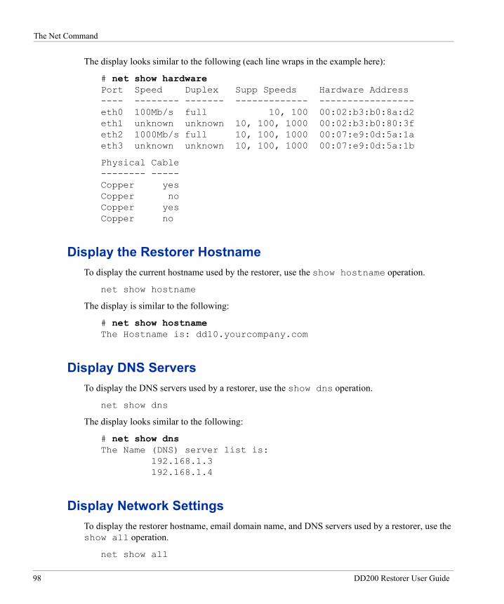
The Net Command
The display looks similar to the following (each line wraps in the example here):
# net show hardware Port Speed Duplex Supp Speeds Hardware Address ---- -------- ------- ------------- ----------------- eth0 100Mb/s full 10, 100 00:02:b3:b0:8a:d2 eth1 unknown unknown 10, 100, 1000 00:02:b3:b0:80:3f eth2 1000Mb/s full 10, 100, 1000 00:07:e9:0d:5a:1a eth3 unknown unknown 10, 100, 1000 00:07:e9:0d:5a:1b
Physical Cable -------- ----- Copper yes Copper no Copper yes Copper no
Display the Restorer HostnameTo display the current hostname used by the restorer, use the show hostname operation.
net show hostname
The display is similar to the following:
# net show hostname The Hostname is: dd10.yourcompany.com
Display DNS ServersTo display the DNS servers used by a restorer, use the show dns operation.
net show dns
The display looks similar to the following:
# net show dns The Name (DNS) server list is:
192.168.1.3 192.168.1.4
Display Network SettingsTo display the restorer hostname, email domain name, and DNS servers used by a restorer, use the show all operation.
net show all
98 DD200 Restorer User Guide
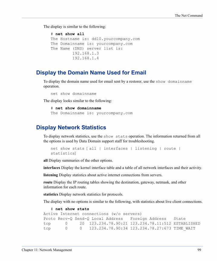
The Net Command
The display is similar to the following:
# net show all The Hostname is: dd10.yourcompany.com The Domainname is: yourcompany.com The Name (DNS) server list is:
192.168.1.3 192.168.1.4
Display the Domain Name Used for EmailTo display the domain name used for email sent by a restorer, use the show domainname operation.
net show domainname
The display looks similar to the following:
# net show domainname The Domainname is: yourcompany.com
Display Network StatisticsTo display network statistics, use the show stats operation. The information returned from all the options is used by Data Domain support staff for troubleshooting.
net show stats [all | interfaces | listening | route | statistics]
all Display summaries of the other options.
interfaces Display the kernel interface table and a table of all network interfaces and their activity.
listening Display statistics about active internet connections from servers.
route Display the IP routing tables showing the destination, gateway, netmask, and other information for each route.
statistics Display network statistics for protocols.
The display with no options is similar to the following, with statistics about live client connections.
# net show stats Active Internet connections (w/o servers) Proto Recv-Q Send-Q Local Address Foreign Address State tcp 0 20 123.234.78.90:21 123.234.78.11:512 ESTABLISHED tcp 0 0 123.234.78.90:34 123.234.78.27:673 TIME_WAIT
Chapter 11: Network Management 99
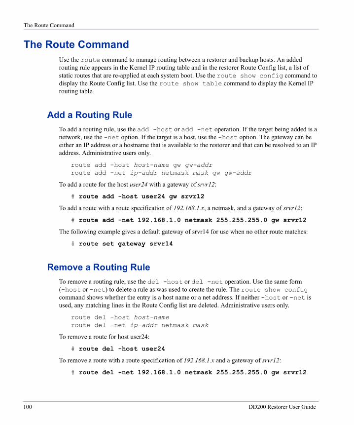
The Route Command
The Route CommandUse the route command to manage routing between a restorer and backup hosts. An added routing rule appears in the Kernel IP routing table and in the restorer Route Config list, a list of static routes that are re-applied at each system boot. Use the route show config command to display the Route Config list. Use the route show table command to display the Kernel IP routing table.
Add a Routing RuleTo add a routing rule, use the add -host or add -net operation. If the target being added is a network, use the -net option. If the target is a host, use the -host option. The gateway can be either an IP address or a hostname that is available to the restorer and that can be resolved to an IP address. Administrative users only.
route add -host host-name gw gw-addr route add -net ip-addr netmask mask gw gw-addr
To add a route for the host user24 with a gateway of srvr12:
# route add -host user24 gw srvr12
To add a route with a route specification of 192.168.1.x, a netmask, and a gateway of srvr12:
# route add -net 192.168.1.0 netmask 255.255.255.0 gw srvr12
The following example gives a default gateway of srvr14 for use when no other route matches:
# route set gateway srvr14
Remove a Routing RuleTo remove a routing rule, use the del -host or del -net operation. Use the same form (-host or -net) to delete a rule as was used to create the rule. The route show config command shows whether the entry is a host name or a net address. If neither -host or -net is used, any matching lines in the Route Config list are deleted. Administrative users only.
route del -host host-name route del -net ip-addr netmask mask
To remove a route for host user24:
# route del -host user24
To remove a route with a route specification of 192.168.1.x and a gateway of srvr12:
# route del -net 192.168.1.0 netmask 255.255.255.0 gw srvr12
100 DD200 Restorer User Guide

The Route Command
Change the Routing Default GatewayTo change the routing default gateway, use the set gateway ipaddr operation. Administrative users only.
route set gateway ipaddr
For example, to set the default routing gateway to the IP address of 192.168.1.2:
# route set gateway 192.168.1.2
Reset the Default Routing GatewayTo reset the default routing gateway to the default value (empty), use the reset operation. Administrative users only.
route reset gateway
Display a RouteTo display a route used by a restorer to connect with a particular destination, use the show trace host operation.
route trace host
For example, to trace the route to srvr24:
# route trace srvr24 Traceroute to srvr24.yourcompany.com (192.168.1.6), 30 hops max, 38 byte packets 1 srvr24 (192.168.1.6) 0.163 ms 0.178 ms 0.147 ms
Display the Configured Static RoutesTo display the configured static routes that are in the Route Config list, use the show config operation.
route show config
The display looks similar to the following (each line in the example wraps):
# route show config The Route Config list is: -host user24 gw srvr12 -net 192.168.1.0 netmask 255.255.255.0 gw srvr12
Chapter 11: Network Management 101
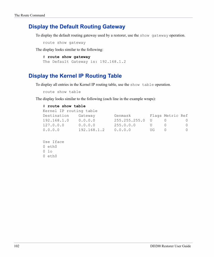
The Route Command
Display the Default Routing GatewayTo display the default routing gateway used by a restorer, use the show gateway operation.
route show gateway
The display looks similar to the following:
# route show gateway The Default Gateway is: 192.168.1.2
Display the Kernel IP Routing TableTo display all entries in the Kernel IP routing table, use the show table operation.
route show table
The display looks similar to the following (each line in the example wraps):
# route show table Kernel IP routing table Destination Gateway Genmask Flags Metric Ref 192.168.1.0 0.0.0.0 255.255.255.0 U 0 0 127.0.0.0 0.0.0.0 255.0.0.0 U 0 0 0.0.0.0 192.168.1.2 0.0.0.0 UG 0 0
Use Iface 0 eth0 0 lo 0 eth0
102 DD200 Restorer User Guide

NFS Management
12
The nfs command manages NFS clients and displays NFS statistics and status. See “nfs” on page 215 for the complete command syntax.NFS functionality is a licensed feature. See “The License Command” on page 34 for licensing details.
A restorer exports the directories /ddvar and /backup. /ddvar contains restorer log files and core files. Add clients from which you will administer the restorer to /ddvar.
/backup is the target for data from your backup servers. The data is compressed before being stored. Add backup servers as clients to /backup. If you choose to add a client to /backup and to /ddvar, consider adding the client as read-only to /backup to guard against accidental deletions of data.
Add NFS ClientsTo add NFS clients that can access the restorer, use the add export client-list nfs-options operation. Add clients for administrative access to /ddvar. Add clients for backup operations to /backup. The client-list can have a comma, a space, or both between list entries. To give access to all clients, the client-list can be an asterisk (*).
nfs add {/ddvar | /backup} client-list [nfs-options]
The client-list can contain IP addresses, hostnames, wildcard hostnames, such as *.yourcompany.com, or a subnet specification.
A subnet specification is either an IP address and a netmask separated by a slash (/), or an IP address and an integer for the number of bits separated by a slash (/). The number of bits is an integer between 8 and 30. Examples for each specification are:
192.168.1.1/255.255.255.0 192.168.1.1/24
103
Remove Clients
The nfs-options list can have a comma, a space, or both between entries. The default NFS options for an NFS client are: rw, no_root_squash, no_all_squash, and secure. The list accepts the following options:
ro Read only permission.
rw Read and write permissions.
root_squash Map requests from uid/gid 0 to the anonymous uid/gid.
no_root_squash Turn off root squashing.
all_squash Map all user requests to the anonymous uid/gid.
no_all_squash Turn off the mapping of all user requests to the anonymous uid/gid.
secure Requires that requests originate on an Internet port that is less than IPPORT_RESERVED (1024).
insecure Turn off the secure option
anonuid=id Set an explicit uid for the anonymous account. The id is an integer bounded from -65635 to 65635.
anongid=id Set an explicit gid for the anonymous account. The id is an integer bounded from -65635 to 65635.
For example, to add an NFS client with an IP address of 192.168.1.02 and read/write access to /ddvar: with the secure option:
# nfs add /ddvar 192.168.1.02 (rw,secure)
Remove ClientsTo remove NFS clients that can access the restorer, use the del export client-list operation. A client can be removed from access to /ddvar and still have access to /backup. The client-list can contain IP addresses, hostnames, and an asterisk (*) and can be comma-separated, space separated, or both.
nfs del {/ddvar | /backup} client-list
For example, to remove an NFS client with an IP address of 192.168.1.02 from /ddvar access:
# nfs del /ddvar 192.168.1.02
Enable ClientsTo allow access for NFS clients to a restorer, use the enable operation.
nfs enable
104 DD200 Restorer User Guide
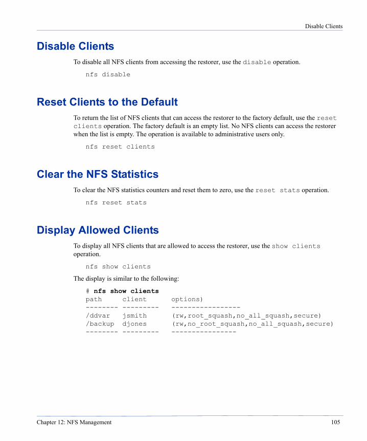
Disable Clients
Disable ClientsTo disable all NFS clients from accessing the restorer, use the disable operation.
nfs disable
Reset Clients to the DefaultTo return the list of NFS clients that can access the restorer to the factory default, use the reset clients operation. The factory default is an empty list. No NFS clients can access the restorer when the list is empty. The operation is available to administrative users only.
nfs reset clients
Clear the NFS StatisticsTo clear the NFS statistics counters and reset them to zero, use the reset stats operation.
nfs reset stats
Display Allowed ClientsTo display all NFS clients that are allowed to access the restorer, use the show clients operation.
nfs show clients
The display is similar to the following:
# nfs show clients path client options) -------- --------- ----------------- /ddvar jsmith (rw,root_squash,no_all_squash,secure) /backup djones (rw,no_root_squash,no_all_squash,secure) -------- --------- ----------------
Chapter 12: NFS Management 105

Display Statistics
Display StatisticsTo display NFS statistics for a restorer, use the show stats operation.
nfs show stats
The following example shows relevant entries, but not all possible entries:
# nfs show stats NFS statistics:
NFSPROC3_NULL :1 NFSPROC3_GETATTR :5 NFSPROC3_SETATTR :2 NFSPROC3_LOOKUP :7 NFSPROC3_ACCESS :4 NFSPROC3_READLINK :0 NFSPROC3_READ :0 NFSPROC3_WRITE :83187 . . . NFSPROC3_COMMIT :1461
Total number of NFS requests handled = 84672
FH statistics: There are currently (2) mounted filesystems.
Stats for mount point: 1 File System Type = SFS Number of cached entries = 2 Number of file handle lookups = 84682 (miss = 2) Max allowed file handle cache size = 200 Number of authentication failures = 0 Number of currently open file streams = 1
Stats for mount point: 2 File System Type = UNIX Number of cached entries = 0 Number of file handle lookups = 0 (miss = 0) Max allowed file handle cache size = 200 Number of authentication failures = 0 Number of currently open file streams = 0
106 DD200 Restorer User Guide
Display Detailed Statistics
Display Detailed StatisticsThe show detailed- stats operation displays statistics used by Data Domain support staff for troubleshooting.
nfs show detailed-stats
Display Active ClientsTo display all NFS clients that have been active on the restorer in the past 15 minutes, use the show active operation.
nfs show active
The display looks similar to the following:
# nfs show active Active Client List:
jsmith.yourcompany.com (/ddvar) djones.yourcompany.com (/backup)
Display Timing for NFS OperationsTo display information about the time needed for NFS operations, use the show histogram operation. Administrative users only.
nfs show histogram
The column headers are:
Op The name of the NFS operation. mean-ms The mathematical mean time for completion of the operations. stddev The standard deviation for time to complete operations, derived from the mean time. max-s The maximum time taken for a single operation. <10ms The number of operations that took less than 10ms. 100ms The number of operations that took between 10ms and 100ms. 1s The number of operations that took between 1 second and 10 seconds. 10s The number of operations that took between 1 second and 10 seconds. >10s The number of operations that took over 10 seconds.
Chapter 12: NFS Management 107
Display Status
Display StatusTo display NFS status for a restorer, use the status operation.
nfs status
The display looks similar to the following:
# nfs status The NFS system is currently active and running Total number of NFS requests handled = 314576
108 DD200 Restorer User Guide

CIFS Management
13
The cifs command manages CIFS (Common Internet File System) backups and restores from and to Windows clients, and displays CIFS statistics and status. See “cifs” on page 183 for the complete command syntax.CIFS functionality is a licensed feature. See “The License Command” on page 34 for licensing details.
CIFS system messages on the restorer go to a CIFS log directory. The location is:
/ddvar/log/samba
Access from Windows to a RestorerFor access to the restorer command line interface, use the SSH (or TELNET if enabled) utility to log into the restorer. For some administrative tasks, such as looking at or transferring a log file, you can connect directly to the /ddvar share on the restorer. A Windows backup user account on a backup client uses the /backup share on the restorer.
Every user account from outside a restorer that needs access to a restorer must have a local account on the restorer, even when using Active Directory as the access mode. To give user access to restorer shares, use the command line interface on the restorer to add the administrative or backup user and to add the client machines from which users access the restorer.
Add a UserTo add a user, use the command user add user-name. The command asks for a password and confirmation or you can include the password as part of the command. CIFS users added to the restorer can have a privilege level of admin or user. The default is user.
Note When a Windows machine connects to a restorer, the user name sent from the Windows machine is all lower case. For the restorer to recognize the user name, the user name added to the restorer must be in lower case.
user add user-name [password password][priv admin | user]
109
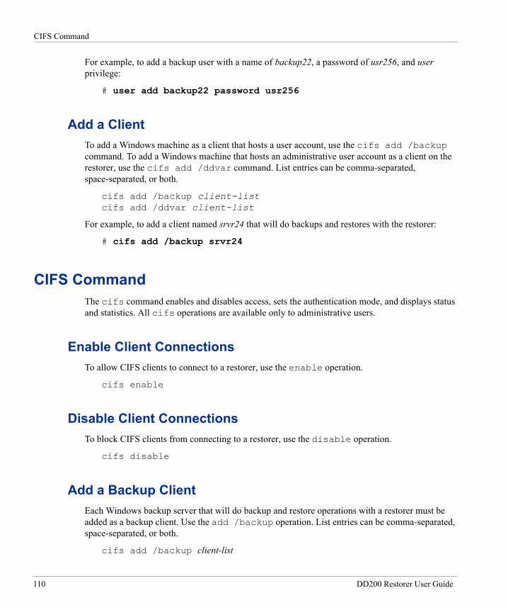
CIFS Command
For example, to add a backup user with a name of backup22, a password of usr256, and user privilege:
# user add backup22 password usr256
Add a ClientTo add a Windows machine as a client that hosts a user account, use the cifs add /backup command. To add a Windows machine that hosts an administrative user account as a client on the restorer, use the cifs add /ddvar command. List entries can be comma-separated, space-separated, or both.
cifs add /backup client-list cifs add /ddvar client-list
For example, to add a client named srvr24 that will do backups and restores with the restorer:
# cifs add /backup srvr24
CIFS CommandThe cifs command enables and disables access, sets the authentication mode, and displays status and statistics. All cifs operations are available only to administrative users.
Enable Client ConnectionsTo allow CIFS clients to connect to a restorer, use the enable operation.
cifs enable
Disable Client ConnectionsTo block CIFS clients from connecting to a restorer, use the disable operation.
cifs disable
Add a Backup ClientEach Windows backup server that will do backup and restore operations with a restorer must be added as a backup client. Use the add /backup operation. List entries can be comma-separated, space-separated, or both.
cifs add /backup client-list
110 DD200 Restorer User Guide

CIFS Command
For example, to add a backup server named srvr24 as a backup client for a restorer:
# cifs add /backup srvr24
Add an Administrative ClientEach Windows machine that will host an administrative user for a restorer must be added as an administrative client. Administrative clients use the /ddvar directory on a restorer. Use the add /ddvar operation. List entries can be comma-separated, space-separated, or both.
cifs add /ddvar client-list
For example, to add an administrative client named srvr22:
# cifs add /ddvar srvr22
Remove a Backup ClientTo remove a Windows backup client, use the del /backup operation. List entries can be comma-separated, space-separated, or both.
cifs del /backup client-list
For example, to remove the backup client srvr24:
# cifs del /backup srvr24
Remove an Administrative ClientTo remove a Windows administrative client, use the del /ddvar operation. List entries can be comma-separated, space-separated, or both.
cifs del /ddvar client-list
For example, to remove the administrative client srvr22:
# cifs del /ddvar srvr24
Remove All CIFS ClientsTo remove all of the CIFS clients from a restorer, use the reset clients operation.
cifs reset clients
Chapter 13: CIFS Management 111

CIFS Command
Set a NetBIOS HostnameTo change the NetBIOS hostname of the restorer, use the set nb-hostname operation.
cifs set nb-hostname nb-name
For example, to give a restorer the name of rstr12 for NetBIOS use:
# cifs set nb-hostname rstr12
Remove the NetBIOS HostnameTo remove the NetBIOS hostname of the restorer, use the reset nb-hostname operation.
cifs reset nb-hostname
Set the Authentication ModeThe restorer can use the authentication modes of: active-directory, domain, or workgroup. Use the set authentication operations to choose or change a mode. Each mode has a separate syntax.
The active-directory mode joins a restorer to an active-directory-enabled domain. The realm must be a fully-qualified name. Data Domain recommends not specifying a domain controller. When not using a domain controller, first specify a WINS server. The restorer must meet all active-directory requirements, such as a clock time that is no more than five minutes different than the domain controller. Domain conroller entries can be comma-separated, space-separated, or both. Optionally, include multiple domain controllers or all ( * ).
cifs set authentication active-directory realm {[dc1[dc2 ...]] | *}
The domain mode puts the restorer into an NT4 domain. Include a domain name and a primary domain controller or backup and primary domain controllers or all ( * ).
cifs set authentication domain domain {[pdc [bdc]] | *}
The workgroup mode means that the restorer verifies user passwords.
cifs set authentication workgroup wg-name
Map an IP Address to a NetBIOS hostnameTo map an IP address with a NetBIOS hostname, use the hosts add operation. The entry is added to the lmhosts file.
cifs hosts add ipaddr nb-hostname ...
112 DD200 Restorer User Guide
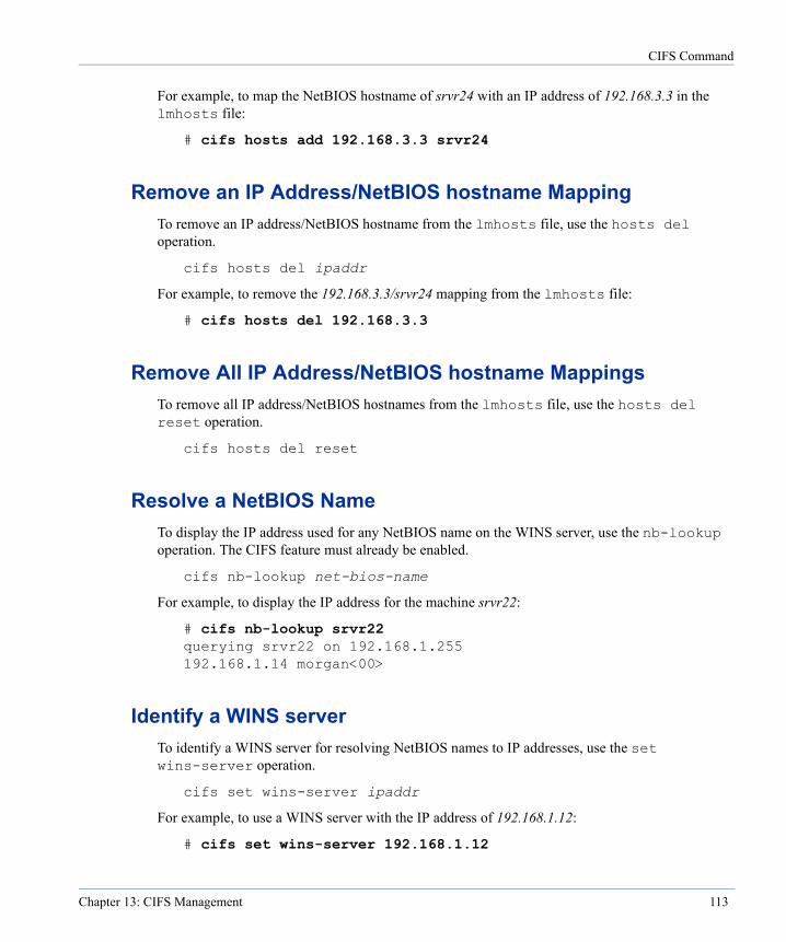
CIFS Command
For example, to map the NetBIOS hostname of srvr24 with an IP address of 192.168.3.3 in the lmhosts file:
# cifs hosts add 192.168.3.3 srvr24
Remove an IP Address/NetBIOS hostname MappingTo remove an IP address/NetBIOS hostname from the lmhosts file, use the hosts del operation.
cifs hosts del ipaddr
For example, to remove the 192.168.3.3/srvr24 mapping from the lmhosts file:
# cifs hosts del 192.168.3.3
Remove All IP Address/NetBIOS hostname MappingsTo remove all IP address/NetBIOS hostnames from the lmhosts file, use the hosts del reset operation.
cifs hosts del reset
Resolve a NetBIOS NameTo display the IP address used for any NetBIOS name on the WINS server, use the nb-lookup operation. The CIFS feature must already be enabled.
cifs nb-lookup net-bios-name
For example, to display the IP address for the machine srvr22:
# cifs nb-lookup srvr22 querying srvr22 on 192.168.1.255 192.168.1.14 morgan<00>
Identify a WINS serverTo identify a WINS server for resolving NetBIOS names to IP addresses, use the set wins-server operation.
cifs set wins-server ipaddr
For example, to use a WINS server with the IP address of 192.168.1.12:
# cifs set wins-server 192.168.1.12
Chapter 13: CIFS Management 113
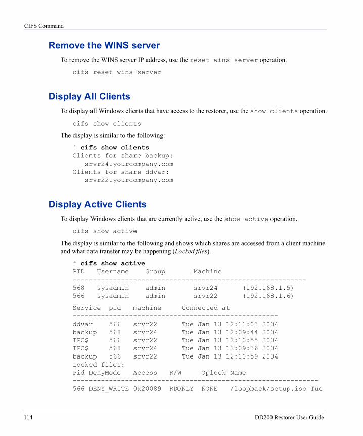
CIFS Command
Remove the WINS serverTo remove the WINS server IP address, use the reset wins-server operation.
cifs reset wins-server
Display All ClientsTo display all Windows clients that have access to the restorer, use the show clients operation.
cifs show clients
The display is similar to the following:
# cifs show clients Clients for share backup:
srvr24.yourcompany.com Clients for share ddvar:
srvr22.yourcompany.com
Display Active ClientsTo display Windows clients that are currently active, use the show active operation.
cifs show active
The display is similar to the following and shows which shares are accessed from a client machine and what data transfer may be happening (Locked files).
# cifs show active PID Username Group Machine ---------------------------------------------------------- 568 sysadmin admin srvr24 (192.168.1.5) 566 sysadmin admin srvr22 (192.168.1.6)
Service pid machine Connected at --------------------------------------------------- ddvar 566 srvr22 Tue Jan 13 12:11:03 2004 backup 568 srvr24 Tue Jan 13 12:09:44 2004 IPC$ 566 srvr22 Tue Jan 13 12:10:55 2004 IPC$ 568 srvr24 Tue Jan 13 12:09:36 2004 backup 566 srvr22 Tue Jan 13 12:10:59 2004 Locked files: Pid DenyMode Access R/W Oplock Name ------------------------------------------------------------- 566 DENY_WRITE 0x20089 RDONLY NONE /loopback/setup.iso Tue
114 DD200 Restorer User Guide
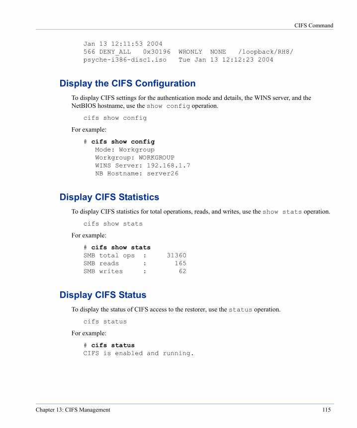
CIFS Command
Jan 13 12:11:53 2004 566 DENY_ALL 0x30196 WRONLY NONE /loopback/RH8/ psyche-i386-disc1.iso Tue Jan 13 12:12:23 2004
Display the CIFS ConfigurationTo display CIFS settings for the authentication mode and details, the WINS server, and the NetBIOS hostname, use the show config operation.
cifs show config
For example:
# cifs show config Mode: Workgroup Workgroup: WORKGROUP WINS Server: 192.168.1.7 NB Hostname: server26
Display CIFS StatisticsTo display CIFS statistics for total operations, reads, and writes, use the show stats operation.
cifs show stats
For example:
# cifs show stats SMB total ops : 31360 SMB reads : 165 SMB writes : 62
Display CIFS StatusTo display the status of CIFS access to the restorer, use the status operation.
cifs status
For example:
# cifs status CIFS is enabled and running.
Chapter 13: CIFS Management 115
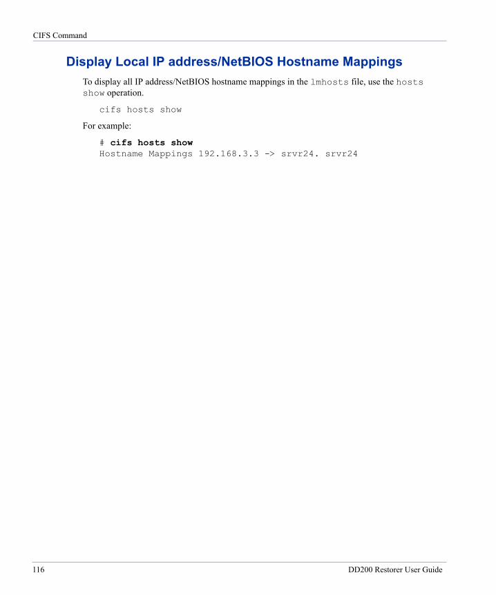
CIFS Command
Display Local IP address/NetBIOS Hostname MappingsTo display all IP address/NetBIOS hostname mappings in the lmhosts file, use the hosts show operation.
cifs hosts show
For example:
# cifs hosts show Hostname Mappings 192.168.3.3 -> srvr24. srvr24
116 DD200 Restorer User Guide
Replicator
14
The replication command sets up and manages the Data Domain Replicator for replication of data between two restorers. The Replicator is a licensed product. Contact Data Domain sales or your Data Domain SE for license keys. Use the license add command to add one key to each restorer in the Replicator pair.A Replicator pair is an originator restorer that receives data from backup servers and a replica restorer that receives data only from the originator. A restorer can be either an originator or a replica, not both. See “replication” on page 221 for the complete command syntax. After replication initialization, the originator constantly checks the status of the replica.
A replica that is removed (with the “break” option on either the originator or replica) from the Replicator pair cannot be brought back into the pair or used as a replica for another originator unless the file system on the replica is emptied with the filesys destroy command.
A replica is a read-only machine for any connection except the originator in the Replicator pair. You can mount a replica as read-only for access from other places; however, after using the “break” option on a replica, the replica itself becomes a read/write machine.
All user information, such as user names, passwords, and permission level (administrative or user), is replicated from the originator to the replica. User information on the replica is overwritten. A change to user information on the originator causes the file to be sent to the replica. A change made on the replica is lost when changes are next made on the originator.
Configure ReplicatorTo configure two restorers as a Replicator pair, use the replication set source orig-name destination replica-name operation. Administrative users only.
• The source orig-name on both the replica and originator must be exactly the same as the name returned by the hostname command on the originator.
• On the originator, the destination replica-name must be a name that can be translated to an IP address or be an IP address.
• On the replica, the destination replica-name must be exactly the same as the name returned by the hostname command on the replica.
117
Start Replication
• When using the replication set command, always run the filesys disable command first and the filesys enable command after.
replication set source orig-name destination replica-name
For example, to create a Replicator pair with restorers named rep1-orig and rep1-rep:
# replication set source rep1-orig destination rep1-rep
Start ReplicationTo start replication between two restorers, use the replication initialize operation on the originator. If the originator holds a lot of data, the initialize operation can take a long time. Consider putting both restorers in the Replicator pair in the same location with a direct (non-network) link to cut down on initialization time. Administrative users only.
replication initialize
Suspend ReplicationTo temporarily halt the replication of data between the restorers, use the replication disable operation on either the originator or the replica. On the originator, the operation stops the sending of data to the replica. On the replica, the operation stops serving the active connection from the originator. If the file system is disabled on either restorer when replication is disabled, replication remains disabled even after the file system is restarted. Administrative users only.
replication disable
Resume ReplicationTo restart replication that is temporarily halted, use the replication enable operation on the restorer that was temporarily halted. On the originator, the operation resumes the sending of data to the replica. On the replica, the operation resumes serving the active connection from the originator. If the file system is disabled on either restorer when replication is enabled, replication is enabled when the file system is restarted. Administrative users only.
replication enable
118 DD400 Restorer User Guide
Remove Replication
Remove ReplicationTo stop all Replicator processes and remove all Replicator configuration from an originator or a replica, use the replication break operation. If the restorer is a replica, it becomes a stand-alone restorer with a standard read/write file system. The break means that the former replica can then be set up as an originator. The replica with its current data can not be used again as a replica. You must run the filesys destroy command on the replica to remove all data in the file system before again using the restorer as a replica.
When using the replication break command, always run the filesys disable command first and the filesys enable command after. Administrative users only.
replication break
Reset Authentication between the RestorersTo reset authentication between restorers, use the replication reauth operation on both the originator and the replica. Messages similar to “Authentication keys out of sync,” or “Key out of sync” signal the need for a reset. Reauthorization is primarily used when replacing an originator restorer. See “Procedure: Replace an Originator” on page 127. Administrative users only.
replication reauth
Move Data to a New OriginatorTo move data from a surviving replica to a new originator, use the replication recover operation on the new originator. The new originator must have the same hostname as the previous originator. Make sure that the new originator is an empty, configured restorer. See “Procedure: Replace an Originator” on page 127. Do not use the operation on a replica. If the replication break command was run earlier, the replica cannot be used to recover an originator. Administrative users only.
replication recover
Change an Originator HostnameIf an originator requires a new hostname, use the replication set source operation on the replica to give the new hostname to the replica. The source orig-name must be exactly the same as displayed by the hostname command on the originator.
When using the replication set command, always run the filesys disable command first and the filesys enable command after. Administrative users only.
replication set source orig-name
Chapter 14: Replicator 119
Change a Replica Hostname
For example, if the local replica rep1-orig is moved from California to New York:
# replication set source rep1-orig.ny.yourcompany.com
Change a Replica HostnameTo give a replica’s new hostname or IP address to an originator after moving the replica, use the replication set destination operation on the originator. If a replica is seeded from an originator at the same geographic location and then later moved to another location (or the hostname or IP address changes for any reason), the originator must have the new hostname or IP address for the replica restorer in the new location. A destination replica-name that is a name must be a name that can be translated to an IP address.
When using the replication set command, always run the filesys disable command first and the filesys enable command after. Administrative users only.
replication set destination replica-name
For example, if the local replica rep1-rep is moved from California to New York:
# replication set destination rep1-rep.ny.yourcompany.com
Add a Scheduled Throttle EventTo change the rate of network bandwidth used by replication, use the throttle add operation. The default network bandwidth use is unlimited.
replication throttle add sched-spec rate
The sched-spec must include:
• One or more three-letter days of the week (such as mon, tue, or wed) or the word daily (to set the schedule every day of the week).
• A time of day in 24 hour military time.
The rate includes a number or the word unlimited. The number can include a tag for bits or bytes per second. Do not use a space between the number and the bits or bytes specification. For example, 2000KB. The default rate is bits per second. In the rate variable:
• bps or b equals raw bits per second
• Kbps, Kb, or K equals 1024 bits per second
• Bps or B equals bytes per second
• KBps or KB equals 1024 bytes per second
120 DD400 Restorer User Guide
Delete a Scheduled Throttle Event
The rate can also be 0 (the zero character), disable, or disabled. Each stops replication until the next rate change.
For example, the following command limits replication to 20 kilobytes per second starting on Mondays and Thursdays at 6:00 a.m.
# replication throttle add mon thu 0600 20KB
Replication runs at the given rate until the next scheduled change or until new throttle commands force a change. The default rate with no scheduled changes is to run as fast as possible at all times.
The add operation may change the current rate. For example, if on Monday at Noon, the current rate is 20 KB, and the schedule that set the current rate started on mon 0600, a new schedule change for Monday at 1100 at a rate of 30 KB (mon 1100 30KB) makes the change immediately.
Note The system enforces a minimum rate of 98,304 bits per second (12 KB).
Delete a Scheduled Throttle EventTo remove one or more throttle schedule entries, use the throttle del operation.
replication throttle del sched-spec
The sched-spec must include:
• One or more three-letter days of the week (such as mon, tue, or wed) or the word daily to delete all entries for the given time.
• A time of day in 24 hour military time.
For example, the following command removes an entry for Mondays at 1100:
# replication throttle del mon 1100
The command may change the current rate. For example, assume that on Monday at Noon, the current rate is 30 KB, and the schedule that set the current rate started on mon 1100. If you now delete the scheduled change for Monday at 1100 (mon 1100), the replication rate immediately changes to the next previous scheduled change, such as mon 0600 20KB.
Set a Temporary Throttle RateTo set a throttle rate until the next scheduled change or until a system reboot, use the throttle set current operation. A temporary rate cannot be set if the replication throttle set override command is in effect.
replication throttle set current rate
Chapter 14: Replicator 121
Set an Override Throttle Rate
The rate includes a number or the word unlimited. The number can include a tag for bits or bytes per second. Do not use a space between the number and the bits or bytes specification. For example, 2000KB. The default rate is bits per second. In the rate variable:
• bps or b equals raw bits per second
• Kbps, Kb, or K equals 1024 bits per second
• Bps or B equals bytes per second
• KBps or KB equals 1024 bytes per second
The rate can also be 0 (the zero character), disable, or disabled. Each stops replication until the next rate change.
As an example, the following command sets the rate to 2000 kilobytes per second:
# replication throttle set current 2000KB
Note The system enforces a minimum rate of 98,304 bits per second (12 KB).
Set an Override Throttle RateTo set a throttle rate that overrides scheduled rate changes, use the throttle set override operation. The rate stays at the override level until the system is rebooted or until another override command is entered. An override cannot be set if the replication throttle set current command is in effect.
replication throttle set override rate
The rate includes a number or the word unlimited. The number can include a tag for bits or bytes per second. Do not use a space between the number and the bits or bytes specification. For example, 2000KB. The default rate is bits per second. In the rate variable:
• bps or b equals raw bits per second
• Kbps, Kb, or K equals 1024 bits per second
• Bps or B equals bytes per second
• KBps or KB equals 1024 bytes per second
The rate can also be 0 (the zero character), disable, or disabled. Each stops replication until the next rate change.
As an example, the following command sets the rate to 2000 kilobytes per second:
# replication throttle set override 2000KB
Note The system enforces a minimum rate of 98,304 bits per second (12 KB).
122 DD400 Restorer User Guide
Reset Throttle Settings
Reset Throttle SettingsTo reset any or all of the throttle settings, use the throttle reset operation.
replication throttle reset {current | override | schedule | all}
• A reset of current removes the rate set by the replication throttle set current command. The rate returns to a scheduled rate or to the default if no rate is scheduled.
• A reset of override removes the rate set by the replication throttle set override command. The rate returns to a scheduled rate or to the default if no rate is scheduled. The default network bandwidth use is unlimited.
• The reset of schedule removes all scheduled change entries. The rate remains at a current or override setting, if either is active, or returns to the default, which is unlimited.
• The reset of all removes any current or override settings and removes all scheduled change entries, returning the system to the default, which is unlimited.
Display Replicator ConfigurationTo display the Replicator role of the current system, the name of the other system in the Replicator pair, and the state of replication, use the show config operation. Administrative users only.
replication show config
The display is similar to the following:
# replication show config Mode: originator Partner: rep22.yourcompany.com Enabled: yes
Chapter 14: Replicator 123

Display Statistics
Display StatisticsTo display Replicator statistics, use the replication show stats operation.
replication show stats
The display is similar to the following:
# replication show stats Bytes sent: 349012554580 Bytes received: 38235336 Virtual bytes replicated: 448155639368 Replica received stamp: Mon Nov 15 15:48:22 2004 Replica processed stamp: Mon Nov 15 15:48:22 2004 Replica records remaining: 0 Originator records remaining: 0 Compressed data remaining: 0
Bytes sent The total number of bytes sent by this side to the other side of the Replicator pair. For the originator, the value includes backup data, replication overhead, and network overhead. For the replica, the value includes replication overhead and network overhead. Use the value (and the next value) to estimate network traffic generated by replication.
Bytes received The total number of bytes received by this side from the other side of the Replicator pair. For the replica, the value includes backup data, replication overhead, and network overhead. For the originator, the value includes replication overhead and network overhead. Use the value (and the previous value) to estimate network traffic generated by replication.
Virtual bytes replicated The total number of bytes of backup data (before compression) replicated since the last time the restorer file system was enabled.
Replica received stamp The date and time of the most recent records received.
Replica processed stamp The date and time of the most recent records processed.
Replica records remaining The number of file records received by the replica and not yet processed.
Originator records remaining The number of file records created by the originator and not yet sent to the replica.
Compressed data remaining New data on the originator that is not yet sent to the replica.
124 DD400 Restorer User Guide
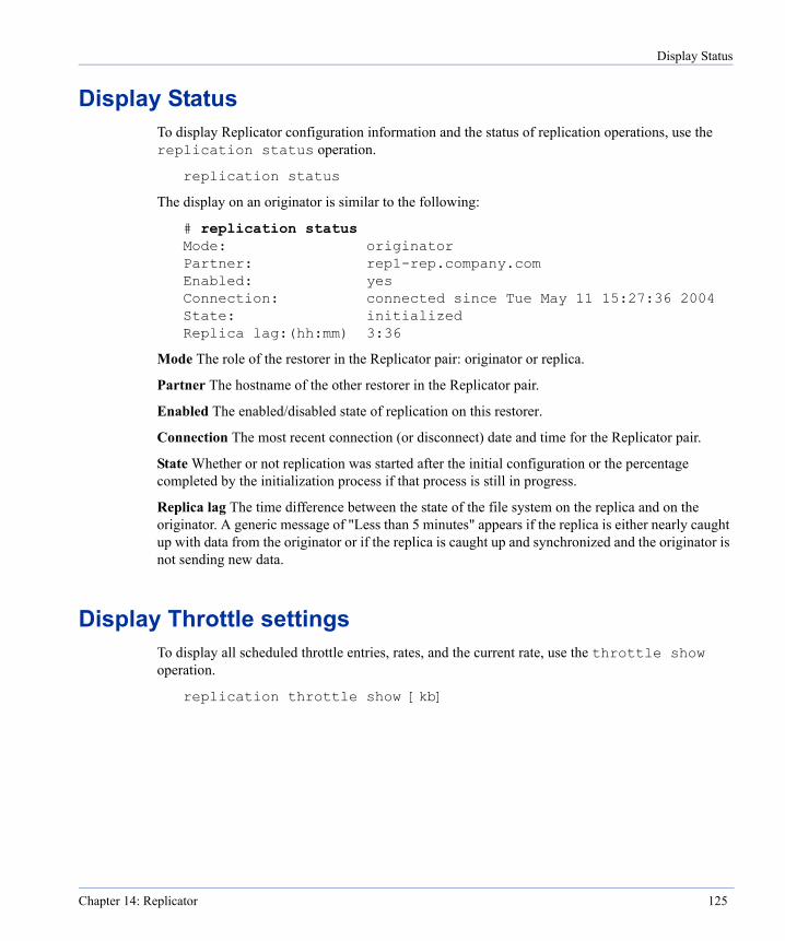
Display Status
Display StatusTo display Replicator configuration information and the status of replication operations, use the replication status operation.
replication status
The display on an originator is similar to the following:
# replication status Mode: originator Partner: rep1-rep.company.com Enabled: yes Connection: connected since Tue May 11 15:27:36 2004 State: initialized Replica lag:(hh:mm) 3:36
Mode The role of the restorer in the Replicator pair: originator or replica.
Partner The hostname of the other restorer in the Replicator pair.
Enabled The enabled/disabled state of replication on this restorer.
Connection The most recent connection (or disconnect) date and time for the Replicator pair.
State Whether or not replication was started after the initial configuration or the percentage completed by the initialization process if that process is still in progress.
Replica lag The time difference between the state of the file system on the replica and on the originator. A generic message of "Less than 5 minutes" appears if the replica is either nearly caught up with data from the originator or if the replica is caught up and synchronized and the originator is not sending new data.
Display Throttle settingsTo display all scheduled throttle entries, rates, and the current rate, use the throttle show operation.
replication throttle show [kb]
Chapter 14: Replicator 125

Procedure: Set Up and Start Replication
The kb option displays the rate in kilobytes per second. Without the option, the rate is displayed in bits per second. The display is similar to the following:
# replication throttle show kb Time Sun Mon Tue Wed Thu Fri Sat ---- --- --- --- --- --- --- --- 06:00 - 90 - - - - - 15:00 - - 200 - - - - 18:00 - - 500 - - - - ---- --- --- --- --- --- --- --- All units in KBps (1024 bytes (8192 bits) per second). Active schedule: Mon, 06:00 at 90 KBps.
Procedure: Set Up and Start ReplicationTo set up and start replication between two restorers:
• Run the following command on both the originator and replica restorers:
filesys disable
• If the replica holds any data, run the following command on the replica:
filesys destroy
• Run the following command on both the originator and replica restorers. See “Configure Replicator” on page 117 for the details of using the command:
replication set source orig-name destination replica-name
• Run the following command on both the originator and replica restorers:
filesys enable
• Run the following command on the originator. The command checks that both restorers in the pair can communicate and starts all Replicator processes. If a problem appears, such as that communication between the restorers is not possible, you do not need to re-initialize after fixing the problem. Replication should begin as soon as the restorers can communicate.
replication initialize
126 DD400 Restorer User Guide
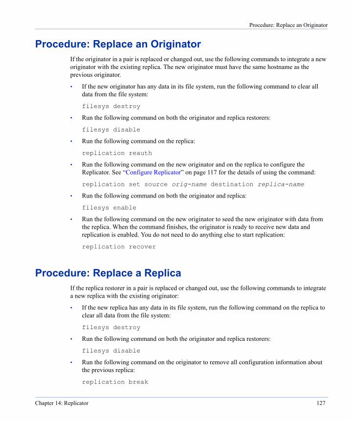
Procedure: Replace an Originator
Procedure: Replace an OriginatorIf the originator in a pair is replaced or changed out, use the following commands to integrate a new originator with the existing replica. The new originator must have the same hostname as the previous originator.
• If the new originator has any data in its file system, run the following command to clear all data from the file system:
filesys destroy
• Run the following command on both the originator and replica restorers:
filesys disable
• Run the following command on the replica:
replication reauth
• Run the following command on the new originator and on the replica to configure the Replicator. See “Configure Replicator” on page 117 for the details of using the command:
replication set source orig-name destination replica-name
• Run the following command on both the originator and replica:
filesys enable
• Run the following command on the new originator to seed the new originator with data from the replica. When the command finishes, the originator is ready to receive new data and replication is enabled. You do not need to do anything else to start replication:
replication recover
Procedure: Replace a ReplicaIf the replica restorer in a pair is replaced or changed out, use the following commands to integrate a new replica with the existing originator:
• If the new replica has any data in its file system, run the following command on the replica to clear all data from the file system:
filesys destroy
• Run the following command on both the originator and replica restorers:
filesys disable
• Run the following command on the originator to remove all configuration information about the previous replica:
replication break
Chapter 14: Replicator 127
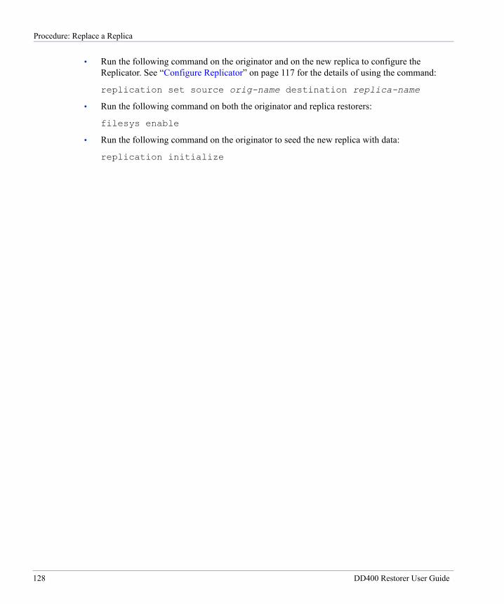
Procedure: Replace a Replica
• Run the following command on the originator and on the new replica to configure the Replicator. See “Configure Replicator” on page 117 for the details of using the command:
replication set source orig-name destination replica-name
• Run the following command on both the originator and replica restorers:
filesys enable
• Run the following command on the originator to seed the new replica with data:
replication initialize
128 DD400 Restorer User Guide
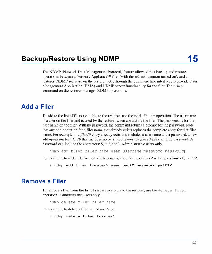
Backup/Restore Using NDMP
15
The NDMP (Network Data Management Protocol) feature allows direct backup and restore operations between a Network Appliance™ filer (with the ndmpd daemon turned on), and a restorer. NDMP software on the restorer acts, through the command line interface, to provide Data Management Application (DMA) and NDMP server functionality for the filer. The ndmp command on the restorer manages NDMP operations.Add a FilerTo add to the list of filers available to the restorer, use the add filer operation. The user name is a user on the filer and is used by the restorer when contacting the filer. The password is for the user name on the filer. With no password, the command returns a prompt for the password. Note that any add operation for a filer name that already exists replaces the complete entry for that filer name. For example, if a filer10 entry already exits and includes a user name and a password, a new add operation for filer10 that includes no password leaves the filer10 entry with no password. A password can include the characters: $, “, ‘, and \. Administrative users only.
ndmp add filer filer_name user username [password password]
For example, to add a filer named toaster5 using a user name of back2 with a password of pw1212:
# ndmp add filer toaster5 user back2 password pw1212
Remove a FilerTo remove a filer from the list of servers available to the restorer, use the delete filer operation. Administrative users only.
ndmp delete filer filer_name
For example, to delete a filer named toaster5:
# ndmp delete filer toaster5
129

Backup from a Filer
Backup from a FilerTo backup data from a filer to a flat file on a restorer, use the get operation. Administrative users only.
ndmp get [incremental level] filer_name:src_tree dst_tree
filer_name The name of the filer that holds the information for the backup operation.
src_tree The directory to backup from the filer.
dst_tree The destination flat file for the backup data on the restorer.
incremental level The numeric level for an incremental backup using a number between 0 (zero) and 9. Using any level greater than 0 backs up only changes since the latest previous backup of the same src_tree with a lower numbered level. Using the get operation without the incremental option is the same as a level 0, or full, backup.
For example, the following command opens a connection to a filer named toaster5 and returns all data under the directory /vol/vol0. The data is stored in a file located at /backup/toaster5/week0 on the restorer.
# ndmp get toaster5:/vol/vol0 /backup/toaster5/week0
The following incremental backup backs up changes since the last full backup.
# ndmp get incremental 1 toaster5:/vol/vol0 \ /backup/toaster5/week0.day1
Restore to a FilerTo restore data from a restorer to a filer, use one of the put operations. Note that a filer may report a successful restore even when one or more files failed restoration. For details, always review the LOG messages sent by the filer. Administrative users only.
ndmp put src_file filer_name:dst_tree
ndmp put partial src_file subdir filer_name:dst_tree
partial Restore a particular directory or file from within a flat file on the restorer. Give the path to the file or subdirectory.
src_file The flat file on the restorer from which to do a restore to a filer. The src_file argument must always begin with /backup.
filer_name The NDMP server to which to send the restored data.
130 DD200 Restorer User Guide
Remove Filer Passwords
dst_tree The destination for the restored data on the NDMP server. Some filers require that subdir be relative to the path used during the ndmp get that created the backup. For example, if the get operation ws for everything under the directory /a/b/c in a tree of /a/b/c/d/e, then the put partial subdirectory argument should start with /d. On some filers, dst_tree must end with a subdir.
The following command restores data from the restorer flat file /backup/ toaster5/week0 to /vol/vol0 on the filer toaster5.
# ndmp put /backup/toaster5/week0 toaster5:/vol/vol0
The following command restores the file .../jsmith/foo from the week0 backup.
# ndmp put partial jsmith/foo /backup/toaster5/week0 toaster5:/vol/vol0/jsmith/foo
Remove Filer PasswordsTo remove all filer passwords stored on the restorer and to write zeros to the disk areas that held them, use the reset filers operation. Administrative users only.
ndmp reset filers
Stop an NDMP ProcessTo stop an NDMP process on the restorer, use the stop operation. The pid is the PID (process ID) number shown for the process in the ndmp status display. A stopped process is cancelled. To restart a process, begin the process again with the get or put commands. Administrative users only.
ndmp stop pid
Stop All NDMP ProcessesTo stop all NDMP processes on a restorer, use the stop all operation. Administrative users only.
ndmp stop all
Chapter 15: Backup/Restore Using NDMP 131
Display Known Filers
Display Known FilersTo display all filers available to the restorer, use the show filers operation. Administrative users only.
ndmp show filers
For example:
# ndmp show filer toaster5 filer name:password ------- ------------- filer1 root:****** filer2 root:****** toaster root:******
Display NDMP Process StatusTo display the status of current NDMP processes on the restorer, use the status operation. The operation labels each process with an identification number. Administrative users only.
ndmp status
The display looks similar to the following and shows the process ID, the command that is currently running, and the total number of megabytes transferred. The following example shows the command entered twice in a row. Note that MB Copied shows the progress of the operation.
# ndmp status PID MB Copied Command --- -------- ------------------------------------------------- 715 3267 get filer1:/vol/vol0/etc /backup/filer1/dumpfile1
# ndmp status PID MB Copied Command --- --------- ------------------------------------------------- 715 4219 get filer1:/vol/vol0/etc /backup/filer1/dumpfile1
132 DD200 Restorer User Guide

Log File Management
16
The log command allows you to view restorer log file entries and to save and clear the log file contents. Messages from the alerts feature, the autosupport reports, and general system messages go to the log directory and into the file messages. A log entry appears for each restorer command given on the system, except for commands using the show action, such as system show stats. The log directory is /ddvar/log. See “log” on page 202 for the complete command syntax.Once a week, the restorer automatically opens new log files and renames the previous files with an appended number of 1 (one) through 9, such as messages.1. Each numbered file is rolled to the next number each week. For example, at the second week, the file messages.1 is rolled to messages.2. If a file messages.2 already existed, it would roll to messages.3. An existing messages.9 is deleted when messages.8 is rolled to messages.9. See “Archive Log Files” on page 135 for instructions on saving log files. The operation takes place every Sunday at 3 a.m.
Display Log FilesTo view the log files, use the view operation. With no filename, the command displays the current messages file. When viewing the log, use the up and down arrows to scroll through the file; use the q key to quit; enter a slash character (/) and a pattern to search through the file.
log view [filename]
The display of the messages file is similar to the following. The last message in the example is an hourly system status message that the restorer generates automatically. The message reports system uptime, the amount of data stored, NFS operations, and the amount of disk space used for data storage (%). The hourly messages go to the system log and to the serial console if one is attached.
# log view Jun 27 12:11:33 localhost rpc.mountd: authenticated unmount request from perfsun-g.datadomain.com:668 for /ddr/col1/segfs (/ddr/col1/segfs) Jun 27 12:28:54 localhost sshd(pam_unix)[998]: session opened for user jsmith10 by (uid=0) Jun 27 13:00:00 localhost logger: at 1:00pm up 3 days, 3:42, 52324 NFS ops, 84763 GB data col. (1%)
133

List Log Files
List Log FilesTo list all of the files in the log directory, use the list operation.
log list
The list is similar to the following:
# log list boot.log messages perf.log space.log ddfs.info messages.1 secure
boot.log Kernel diagnostic messages generated during the booting up process.
ddfs.info Debugging information created by the file system process.
destroy.id_number.log All of the actions taken by an instance of the filesys destroy command. Each instance produces a log with a unique ID number.
messages The system log, which is generated by restorer actions and from general system operations.
perf.log Performance statistics used by Data Domain support staff for system tuning.
secure Messages from successful logins, attempted logins, and attempts to do operations for which a user does not have permission.
space.log Messages about disk space use by restorer components and data storage, and messages from the clean process. A space use message is generated every hour. Each time the clean process runs, it creates about 100 messages. All the messages are in comma-separated- value format with tags that you can use to separate out the disk space or clean messages. You can use third-party software to analyse either set of messages. The tags are:
CLEAN for data lines from clean operations.
CLEAN_HEADER for lines that contain headers for the clean operations data lines.
SPACE for disk space data lines.
SPACE_HEADER for lines that contain headers for the disk space data lines.
Scroll New Log EntriesTo display a view of the messages file that adds new entries as they occur, use the watch operation. Use the key combination <Control> c to break out of the watch operation. With no filename, the command displays the current messages file.
log watch [filename]
134 DD200 Restorer User Guide
Archive Log Files
Archive Log FilesTo archive log files, use FTP to copy the files to another machine.
1. On the restorer, use the adminaccess show ftp command to see that the FTP service is enabled. If the service is not enabled, use the command adminaccess enable ftp.
2. On the restorer, use the adminaccess show ftp command to see that the FTP access list has the IP address of your remote machine or a class-C address that includes your remote machine. If the address is not in the list, use the command adminaccess add ftp <ipaddr>.
3. On the remote machine, open a web browser.
4. In the Address box at the top of the web browser, use FTP to access the restorer. For example:
ftp://restorer_name.yourcompany.com/
Note Some web browsers do not automatically ask for a login if a machine does not accept anonymous logins. In that case, add a user name and password to the FTP line. For example: ftp://sysadmin:your-pw@restorer_name.yourcompany.com
5. At the login popup, log into the restorer as user sysadmin.
6. On the restorer, you are in the directory just above the log directory. Open the log directory to list the messages files.
7. Copy the file that you want to save. Right-click on the file icon and select Copy To Folder from the menu. Choose a location for the file copy.
8. If you want the FTP service disabled on the restorer, use SSH to log into the restorer as sysadmin and give the command adminaccess disable ftp.
Chapter 16: Log File Management 135

Archive Log Files
136 DD200 Restorer User Guide

Hardware Servicing
17
In the restorer, you can replace disks, fans, power supplies, the NVRAM card, disk controller cards, and add or replace the Fiber Gigabit Ethernet card. Data Domain recommends timely replacement of components that generate error log messages for failures or are out of normal operating tolerances. Check with Data Domain Support staff for what constitutes excessive error messages and out-of-range operating tolerances. After an error message, a component can continue to degrade, leading to an automatic system shutdown. For example, the restorer generates a warning message if the interior temperature of the machine reaches 47 degrees centigrade. If the temperature reaches 50 degrees centigrade, the machine shuts down.As an addition to error log messages, you can check components by using the restorer command system show faults, which shows the general health of hardware subsystems. A normal system returns messages similar to the following:
# system show faults Hardware Fault Summary ---------------------- Power Supply Voltage Error Summary:
No power supply errors detected.
Temperature Extremes Summary: No temperature extremes detected.
Fan Failure Summary: No fan failures detected.
• If a power supply unit fails, the Power Supply... entry has the message: A power supply module has failed. To replace a power supply, see “Replace Power Units” on page 141. For system restart tips after replacing power supplies, see “System Restart” on page 144.
• The Temperature Extremes... summary displays information about CPU temperatures and contains an entry if the overall machine temperature is above an acceptable level.
- If the overall temperature for the machine reaches 47 degrees centigrade, a warning message is generated. If the temperature reaches 50 degrees centigrade, the machine shuts down.
137

Replace Disks
- If a CPU temperature reaches 60 degrees centigrade, a warning message is generated. If a CPU temperature reaches 74 degrees centigrade, the machine shuts down.
• If one or more fans have failed or are running below the minimum required speed, the Fan Failure ... summary lists the failed or failing fans. To replace a fan, see “Replace Fans” on page 147.
Replace DisksNote Please return the failed/replaced disk to Data Domain. Reuse the packaging from the new
disk and use the included prepaid waybill for shipping. Reference the RMA number on the outside of the package. Returns with no RMA number cannot be accepted.
If a disk reaches a temperature of 35 degrees centigrade, a warning message is generated. To display details for disk hardware status, use the disk show reliability-data command. The display is similar to the following:
# disk show reliability-data Disk ATA Bus Command Command Drive Awaiting Already Temp Soft Err Timeouts Faults Soft Err Realloc Realloc ------ -------- -------- ------- -------- ------- ------- ---- disk1 0 0 0/ 0/ 0 6/ 0 0 0 28 C disk2 0 0 0/ 0/ 0 0/ 0 0 0 35 C disk3 0 0 0/ 0/ 0 10/ 0 0 0 30 C . . .
A restorer has 16 disks. Each disk has two LEDs The right LED on each disk glows green when the disk has power and red when the disk has failed. The left LED on each disk glows green when the disk is accessed by software. Figure 8 shows the disk numbering scheme as seen from the front of the restorer.
1
2
3
4
5
6
7
89
10
11
12
1314
15
16
Figure 8: Disk numbering
138 DD200 Restorer User Guide
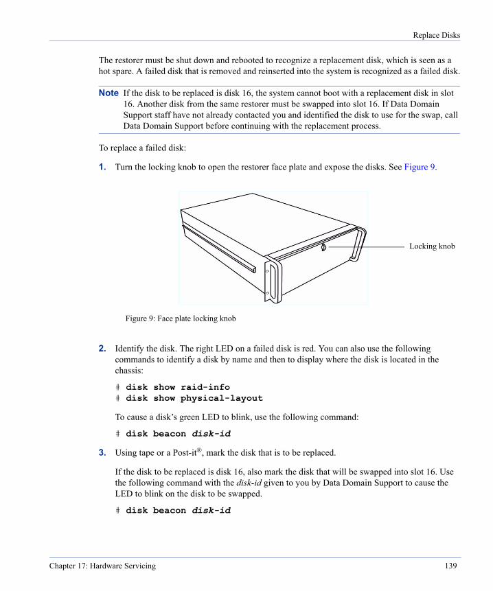
Replace Disks
The restorer must be shut down and rebooted to recognize a replacement disk, which is seen as a hot spare. A failed disk that is removed and reinserted into the system is recognized as a failed disk.
Note If the disk to be replaced is disk 16, the system cannot boot with a replacement disk in slot 16. Another disk from the same restorer must be swapped into slot 16. If Data Domain Support staff have not already contacted you and identified the disk to use for the swap, call Data Domain Support before continuing with the replacement process.
To replace a failed disk:
1. Turn the locking knob to open the restorer face plate and expose the disks. See Figure 9.
2. Identify the disk. The right LED on a failed disk is red. You can also use the following commands to identify a disk by name and then to display where the disk is located in the chassis:
# disk show raid-info # disk show physical-layout
To cause a disk’s green LED to blink, use the following command:
# disk beacon disk-id
3. Using tape or a Post-it®, mark the disk that is to be replaced.
If the disk to be replaced is disk 16, also mark the disk that will be swapped into slot 16. Use the following command with the disk-id given to you by Data Domain Support to cause the LED to blink on the disk to be swapped.
# disk beacon disk-id
Figure 9: Face plate locking knob
Locking knob
Chapter 17: Hardware Servicing 139
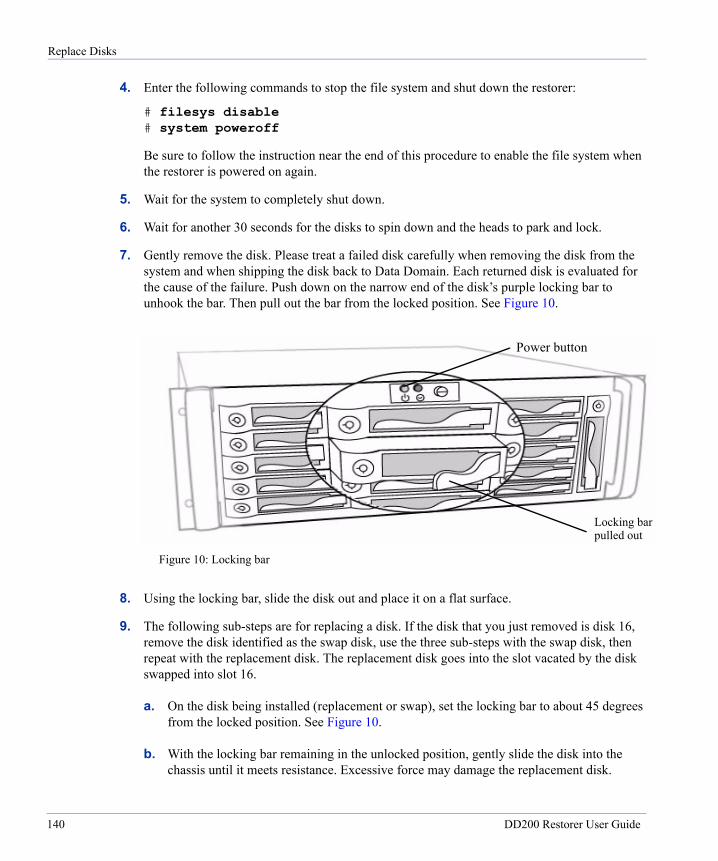
Replace Disks
4. Enter the following commands to stop the file system and shut down the restorer:
# filesys disable # system poweroff
Be sure to follow the instruction near the end of this procedure to enable the file system when the restorer is powered on again.
5. Wait for the system to completely shut down.
6. Wait for another 30 seconds for the disks to spin down and the heads to park and lock.
7. Gently remove the disk. Please treat a failed disk carefully when removing the disk from the system and when shipping the disk back to Data Domain. Each returned disk is evaluated for the cause of the failure. Push down on the narrow end of the disk’s purple locking bar to unhook the bar. Then pull out the bar from the locked position. See Figure 10.
8. Using the locking bar, slide the disk out and place it on a flat surface.
9. The following sub-steps are for replacing a disk. If the disk that you just removed is disk 16, remove the disk identified as the swap disk, use the three sub-steps with the swap disk, then repeat with the replacement disk. The replacement disk goes into the slot vacated by the disk swapped into slot 16.
a. On the disk being installed (replacement or swap), set the locking bar to about 45 degrees from the locked position. See Figure 10.
b. With the locking bar remaining in the unlocked position, gently slide the disk into the chassis until it meets resistance. Excessive force may damage the replacement disk.
Figure 10: Locking bar
Locking barpulled out
Power button
140 DD200 Restorer User Guide
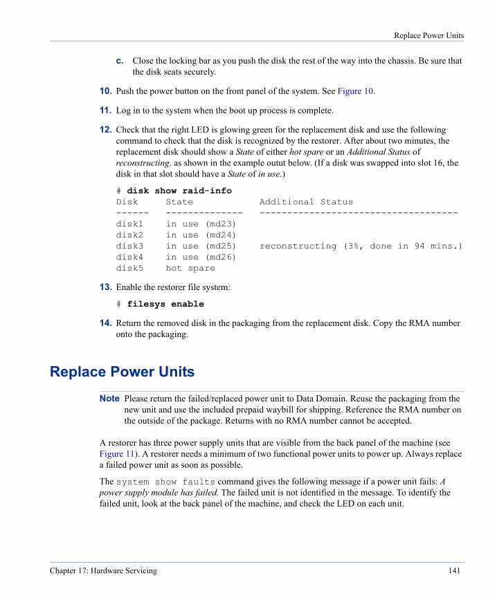
Replace Power Units
c. Close the locking bar as you push the disk the rest of the way into the chassis. Be sure that the disk seats securely.
10. Push the power button on the front panel of the system. See Figure 10.
11. Log in to the system when the boot up process is complete.
12. Check that the right LED is glowing green for the replacement disk and use the following command to check that the disk is recognized by the restorer. After about two minutes, the replacement disk should show a State of either hot spare or an Additional Status of reconstructing. as shown in the example outut below. (If a disk was swapped into slot 16, the disk in that slot should have a State of in use.)
# disk show raid-info Disk State Additional Status ------ -------------- ------------------------------------ disk1 in use (md23) disk2 in use (md24) disk3 in use (md25) reconstructing (3%, done in 94 mins.) disk4 in use (md26) disk5 hot spare
13. Enable the restorer file system:
# filesys enable
14. Return the removed disk in the packaging from the replacement disk. Copy the RMA number onto the packaging.
Replace Power UnitsNote Please return the failed/replaced power unit to Data Domain. Reuse the packaging from the
new unit and use the included prepaid waybill for shipping. Reference the RMA number on the outside of the package. Returns with no RMA number cannot be accepted.
A restorer has three power supply units that are visible from the back panel of the machine (see Figure 11). A restorer needs a minimum of two functional power units to power up. Always replace a failed power unit as soon as possible.
The system show faults command gives the following message if a power unit fails: A power supply module has failed. The failed unit is not identified in the message. To identify the failed unit, look at the back panel of the machine, and check the LED on each unit.
Chapter 17: Hardware Servicing 141
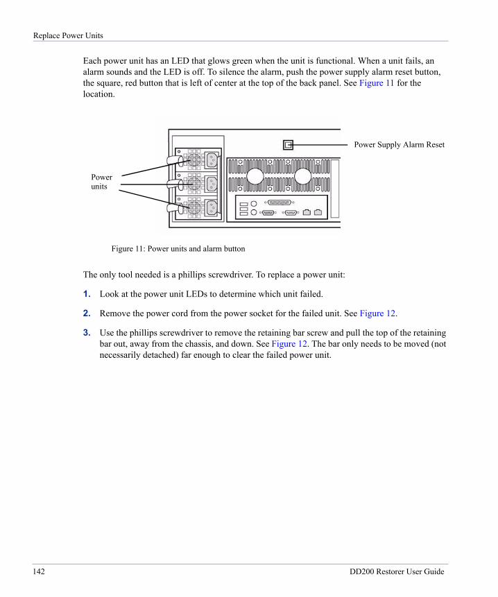
Replace Power Units
Each power unit has an LED that glows green when the unit is functional. When a unit fails, an alarm sounds and the LED is off. To silence the alarm, push the power supply alarm reset button, the square, red button that is left of center at the top of the back panel. See Figure 11 for the location.
The only tool needed is a phillips screwdriver. To replace a power unit:
1. Look at the power unit LEDs to determine which unit failed.
2. Remove the power cord from the power socket for the failed unit. See Figure 12.
3. Use the phillips screwdriver to remove the retaining bar screw and pull the top of the retaining bar out, away from the chassis, and down. See Figure 12. The bar only needs to be moved (not necessarily detached) far enough to clear the failed power unit.
Figure 11: Power units and alarm button
Power Supply Alarm Reset
Powerunits
142 DD200 Restorer User Guide
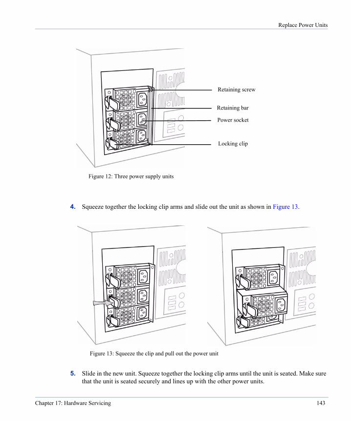
Replace Power Units
4. Squeeze together the locking clip arms and slide out the unit as shown in Figure 13.
5. Slide in the new unit. Squeeze together the locking clip arms until the unit is seated. Make sure that the unit is seated securely and lines up with the other power units.
Figure 12: Three power supply units
Locking clip
Power socket
Retaining screw
Retaining bar
Figure 13: Squeeze the clip and pull out the power unit
Chapter 17: Hardware Servicing 143
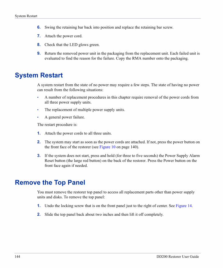
System Restart
6. Swing the retaining bar back into position and replace the retaining bar screw.
7. Attach the power cord.
8. Check that the LED glows green.
9. Return the removed power unit in the packaging from the replacement unit. Each failed unit is evaluated to find the reason for the failure. Copy the RMA number onto the packaging.
System RestartA system restart from the state of no power may require a few steps. The state of having no power can result from the following situations:
• A number of replacement procedures in this chapter require removal of the power cords from all three power supply units.
• The replacement of multiple power supply units.
• A general power failure.
The restart procedure is:
1. Attach the power cords to all three units.
2. The system may start as soon as the power cords are attached. If not, press the power button on the front face of the restorer (see Figure 10 on page 140).
3. If the system does not start, press and hold (for three to five seconds) the Power Supply Alarm Reset button (the large red button) on the back of the restorer. Press the Power button on the front face again if needed.
Remove the Top PanelYou must remove the restorer top panel to access all replacement parts other than power supply units and disks. To remove the top panel:
1. Undo the locking screw that is on the front panel just to the right of center. See Figure 14.
2. Slide the top panel back about two inches and then lift it off completely.
144 DD200 Restorer User Guide
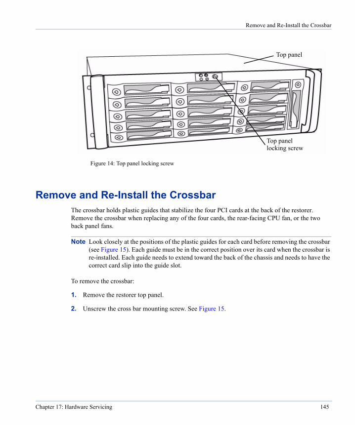
Remove and Re-Install the Crossbar
Remove and Re-Install the CrossbarThe crossbar holds plastic guides that stabilize the four PCI cards at the back of the restorer. Remove the crossbar when replacing any of the four cards, the rear-facing CPU fan, or the two back panel fans.
Note Look closely at the positions of the plastic guides for each card before removing the crossbar (see Figure 15). Each guide must be in the correct position over its card when the crossbar is re-installed. Each guide needs to extend toward the back of the chassis and needs to have the correct card slip into the guide slot.
To remove the crossbar:
1. Remove the restorer top panel.
2. Unscrew the cross bar mounting screw. See Figure 15.
Figure 14: Top panel locking screw
Top panellocking screw
Top panel
Chapter 17: Hardware Servicing 145

Remove and Re-Install the Crossbar
3. Raise the mounting screw end of the crossbar until you can easily pull out the tab that holds the other end of the crossbar to the chassis. See Figure 16.
Figure 15: Crossbar
Crossbar
Mountingscrew
Plastic guides
Figure 16: Raising the crossbar
146 DD200 Restorer User Guide
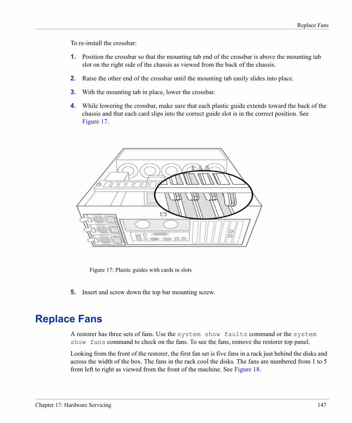
Replace Fans
To re-install the crossbar:
1. Position the crossbar so that the mounting tab end of the crossbar is above the mounting tab slot on the right side of the chassis as viewed from the back of the chassis.
2. Raise the other end of the crossbar until the mounting tab easily slides into place.
3. With the mounting tab in place, lower the crossbar.
4. While lowering the crossbar, make sure that each plastic guide extends toward the back of the chassis and that each card slips into the correct guide slot is in the correct position. See Figure 17.
5. Insert and screw down the top bar mounting screw.
Replace FansA restorer has three sets of fans. Use the system show faults command or the system show fans command to check on the fans. To see the fans, remove the restorer top panel.
Looking from the front of the restorer, the first fan set is five fans in a rack just behind the disks and across the width of the box. The fans in the rack cool the disks. The fans are numbered from 1 to 5 from left to right as viewed from the front of the machine. See Figure 18.
Figure 17: Plastic guides with cards in slots
Chapter 17: Hardware Servicing 147

Replace Fans
The second fan set is two fans located one on each system CPU. The fans are numbered from 2 to 1 from left to right as viewed from the front of the restorer. The fan for CPU 2 is on the back of the CPU, as shown in Figure 18. The fan for CPU 1 is on the front of the CPU and is not visible in Figure 18.
The third fan set is two fans on the back panel, as shown in Figure 18. Back panel fans are numbered 1 and 2 from left to right as viewed from the front of the restorer.
Replace Disk FansDisk fans are numbered 1 through 5 from left to right as viewed from the front of the restorer. You can replace disk fans while the restorer is running. To replace disk fans:
1. Check the system show faults command or the system show fans command output to determine that a fan is failed.
2. Remove the restorer top panel.
3. For the failed fan, undo the fan retaining screw at the top of the fan frame. The screw releases the fan and frame, but remains in the frame. See Figure 19.
Disk fan 5
CPU 2 fan
Back panel fan 1
Figure 18: Fan locations
CPU 1
Back panel fan 2
Disk fan 4Disk fan 3Disk fan 2Disk fan 1
148 DD200 Restorer User Guide
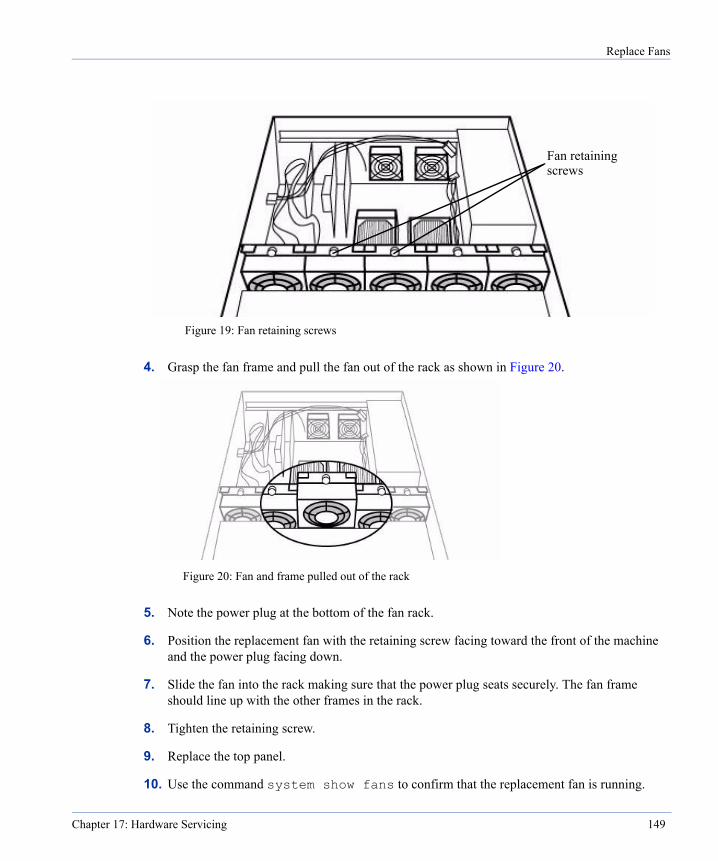
Replace Fans
4. Grasp the fan frame and pull the fan out of the rack as shown in Figure 20.
5. Note the power plug at the bottom of the fan rack.
6. Position the replacement fan with the retaining screw facing toward the front of the machine and the power plug facing down.
7. Slide the fan into the rack making sure that the power plug seats securely. The fan frame should line up with the other frames in the rack.
8. Tighten the retaining screw.
9. Replace the top panel.
10. Use the command system show fans to confirm that the replacement fan is running.
Figure 19: Fan retaining screws
Fan retainingscrews
Figure 20: Fan and frame pulled out of the rack
Chapter 17: Hardware Servicing 149
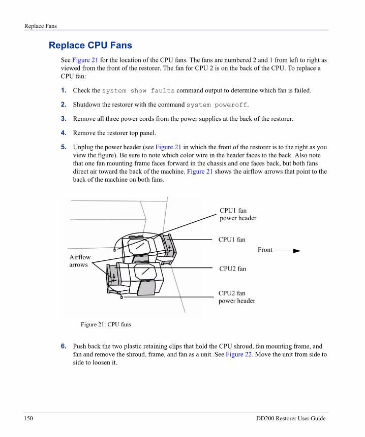
Replace Fans
Replace CPU FansSee Figure 21 for the location of the CPU fans. The fans are numbered 2 and 1 from left to right as viewed from the front of the restorer. The fan for CPU 2 is on the back of the CPU. To replace a CPU fan:
1. Check the system show faults command output to determine which fan is failed.
2. Shutdown the restorer with the command system poweroff.
3. Remove all three power cords from the power supplies at the back of the restorer.
4. Remove the restorer top panel.
5. Unplug the power header (see Figure 21 in which the front of the restorer is to the right as you view the figure). Be sure to note which color wire in the header faces to the back. Also note that one fan mounting frame faces forward in the chassis and one faces back, but both fans direct air toward the back of the machine. Figure 21 shows the airflow arrows that point to the back of the machine on both fans.
6. Push back the two plastic retaining clips that hold the CPU shroud, fan mounting frame, and fan and remove the shroud, frame, and fan as a unit. See Figure 22. Move the unit from side to side to loosen it.
Figure 21: CPU fans
CPU1 fanpower header
CPU1 fan
CPU2 fanpower header
CPU2 fan
FrontAirflowarrows
150 DD200 Restorer User Guide

Replace Fans
7. Push back the plastic retaining clips that hold the fan, and pull the fan from the frame. See Figure 23.
8. Slide the replacement fan into the two retaining clips.
Note Each CPU fan must direct airflow to the back of the restorer. Each fan frame has an arrow that shows airflow direction. Be sure that the arrow points to the back of the restorer. See Figure 21. The arrow for the fan on the CPU 1 shroud should point back toward the shroud. The arrow for the fan on the CPU 2 shroud should point away from the shroud.
9. Replace the unit of shroud, fan mounting frame, and fan.
Figure 22: Remove the CPU shroud
Figure 23: Remove the fan from the shroud (Note airflow arrow on this fan for CPU 2.)
Chapter 17: Hardware Servicing 151

Replace Fans
10. Attach the power connector to the power header on the motherboard at the location shown in Figure 21. Be sure to have the correct color wire in the connector facing to the back of the machine.
11. Replace the restorer top panel.
12. Replace the power cords and restart the restorer. See “System Restart” on page 144 for restart tips.
13. Use the command system show fans to confirm that the replacement fan is running.
Replace Back Panel FansBack panel fans are numbered 1 and 2 from left to right as viewed from the front of the restorer. The two fans are replaced as one unit. If one fan in the unit fails, both fans are replaced. The only tool needed is a phillips screwdriver. To remove the unit:
1. Check the system show faults command output to determine which fan is failed.
2. Shutdown the restorer with the command system poweroff.
3. Remove all three power cords from the power supplies at the back of the restorer.
4. Remove the restorer top panel.
5. Unplug both monitor headers. See Figure 24. Be sure to note which color wire faces toward the back of the machine.
152 DD200 Restorer User Guide

Replace Fans
6. Unhook the power harness that services both fans. See Figure 24
7. Using a phillips screwdriver, remove the four screws that hold each fan on the chassis back panel. See Figure 25.
8. From inside the chassis, pull out the fans and wiring harness. See Figure 26. Note that the harness has two power connectors. The four-pin male connector is used for power to the fans; the other connector is not used.
Figure 24: Back panel fans
Monitor headers
Powerharness
Figure 25: Fan mounting screws
Fan 2 mounting screws Fan 1 mounting screws
Chapter 17: Hardware Servicing 153
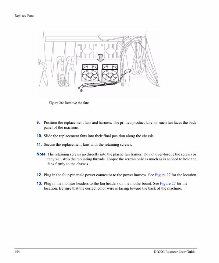
Replace Fans
9. Position the replacement fans and harness. The printed product label on each fan faces the back panel of the machine.
10. Slide the replacement fans into their final position along the chassis.
11. Secure the replacement fans with the retaining screws.
Note The retaining screws go directly into the plastic fan frames. Do not over-torque the screws or they will strip the mounting threads. Torque the screws only as much as is needed to hold the fans firmly to the chassis.
12. Plug in the four-pin male power connector to the power harness. See Figure 27 for the location.
13. Plug in the monitor headers to the fan headers on the motherboard. See Figure 27 for the location. Be sure that the correct color wire is facing toward the back of the machine.
Figure 26: Remove the fans
154 DD200 Restorer User Guide
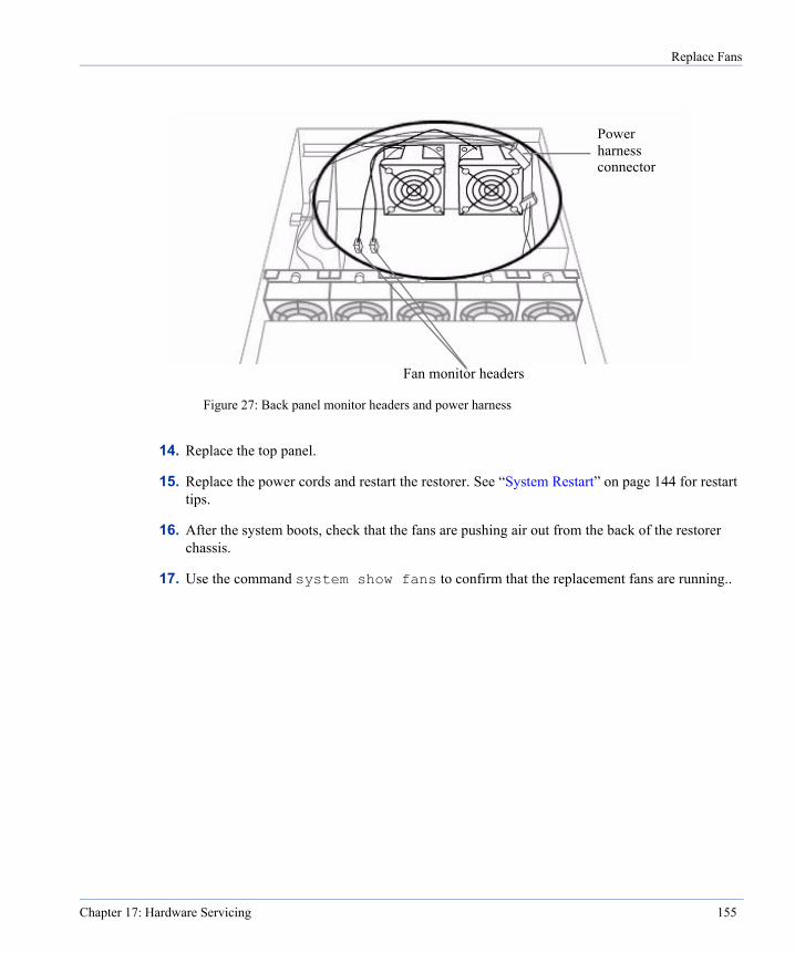
Replace Fans
14. Replace the top panel.
15. Replace the power cords and restart the restorer. See “System Restart” on page 144 for restart tips.
16. After the system boots, check that the fans are pushing air out from the back of the restorer chassis.
17. Use the command system show fans to confirm that the replacement fans are running..
Figure 27: Back panel monitor headers and power harness
Fan monitor headers
Powerharnessconnector
Chapter 17: Hardware Servicing 155
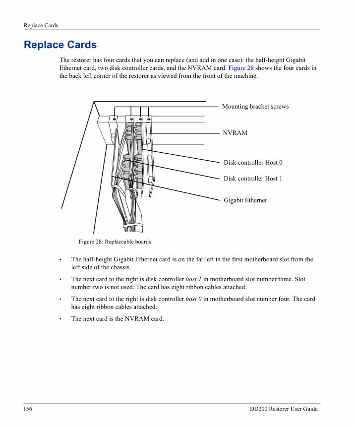
Replace Cards
Replace CardsThe restorer has four cards that you can replace (and add in one case): the half-height Gigabit Ethernet card, two disk controller cards, and the NVRAM card. Figure 28 shows the four cards in the back left corner of the restorer as viewed from the front of the machine.
• The half-height Gigabit Ethernet card is on the far left in the first motherboard slot from the left side of the chassis.
• The next card to the right is disk controller host 1 in motherboard slot number three. Slot number two is not used. The card has eight ribbon cables attached.
• The next card to the right is disk controller host 0 in motherboard slot number four. The card has eight ribbon cables attached.
• The next card is the NVRAM card.
Figure 28: Replaceable boards
NVRAM
Disk controller Host 0
Disk controller Host 1
Gigabit Ethernet
Mounting bracket screws
156 DD200 Restorer User Guide

Replace Cards
Add or Replace a Gigabit Ethernet CardThe optional half-height Gigabit Ethernet card adds two Gigabit Ethernet Fiber or copper ports to the restorer. A restorer with the card has a total of four Ethernet ports, including the copper Gigabit Ethernet port and copper 10/100 Base-T port on the motherboard. Figure 29 shows the four ports.
Figure 29: Ethernet interfaces
10/100 Base-T CopperFiber
GigabitGigabit Fiber
Gigabit
Chapter 17: Hardware Servicing 157

Replace Cards
Figure 30, looking from the back of the restorer, shows the location of an installed card with the crossbar and plastic guide in place. The correct slot in the motherboard is the slot closest to the right side of the chassis when looking from the back of the restorer.
To install a Gigabit Ethernet card:
1. Shutdown the system with the system poweroff command.
2. Remove the power cords.
3. Remove the restorer top panel.
4. Remove the crossbar. Be sure to note the positions of the plastic guides for each card secured by the crossbar.
5. To remove a Gigabit Ethernet card, unscrew the mounting bracket screw that holds the card to the chassis (see Figure 28) and then remove the card from the slot. See Figure 31.
FiberGigabit
Figure 30: Gigabit Ethernet card location
Plastic guide
Ethernetcard
158 DD200 Restorer User Guide
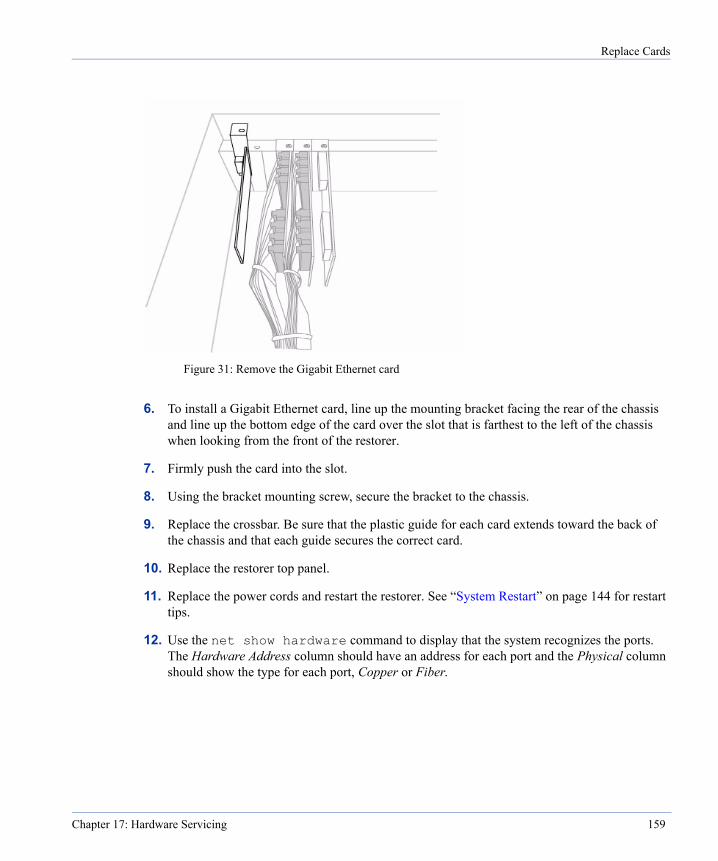
Replace Cards
6. To install a Gigabit Ethernet card, line up the mounting bracket facing the rear of the chassis and line up the bottom edge of the card over the slot that is farthest to the left of the chassis when looking from the front of the restorer.
7. Firmly push the card into the slot.
8. Using the bracket mounting screw, secure the bracket to the chassis.
9. Replace the crossbar. Be sure that the plastic guide for each card extends toward the back of the chassis and that each guide secures the correct card.
10. Replace the restorer top panel.
11. Replace the power cords and restart the restorer. See “System Restart” on page 144 for restart tips.
12. Use the net show hardware command to display that the system recognizes the ports. The Hardware Address column should have an address for each port and the Physical column should show the type for each port, Copper or Fiber.
Figure 31: Remove the Gigabit Ethernet card
Chapter 17: Hardware Servicing 159
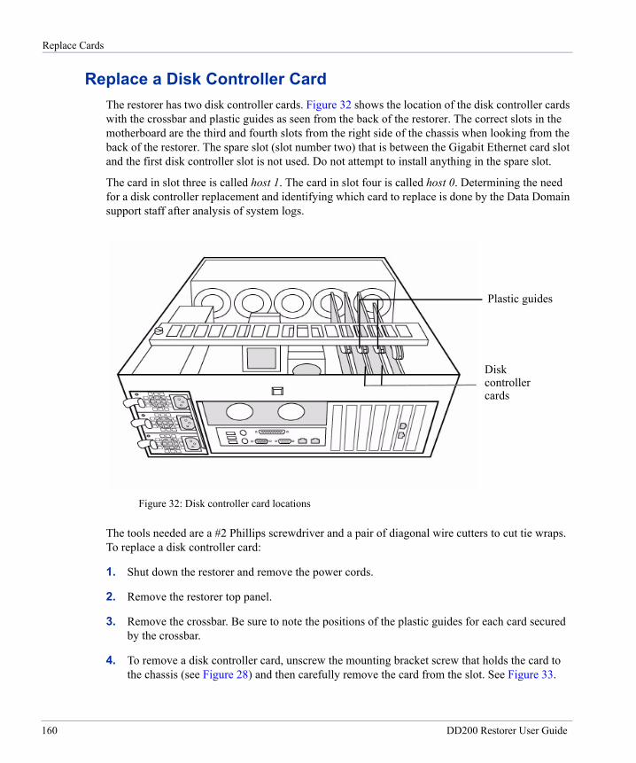
Replace Cards
Replace a Disk Controller CardThe restorer has two disk controller cards. Figure 32 shows the location of the disk controller cards with the crossbar and plastic guides as seen from the back of the restorer. The correct slots in the motherboard are the third and fourth slots from the right side of the chassis when looking from the back of the restorer. The spare slot (slot number two) that is between the Gigabit Ethernet card slot and the first disk controller slot is not used. Do not attempt to install anything in the spare slot.
The card in slot three is called host 1. The card in slot four is called host 0. Determining the need for a disk controller replacement and identifying which card to replace is done by the Data Domain support staff after analysis of system logs.
The tools needed are a #2 Phillips screwdriver and a pair of diagonal wire cutters to cut tie wraps. To replace a disk controller card:
1. Shut down the restorer and remove the power cords.
2. Remove the restorer top panel.
3. Remove the crossbar. Be sure to note the positions of the plastic guides for each card secured by the crossbar.
4. To remove a disk controller card, unscrew the mounting bracket screw that holds the card to the chassis (see Figure 28) and then carefully remove the card from the slot. See Figure 33.
Diskcontrollercards
Figure 32: Disk controller card locations
Plastic guides
160 DD200 Restorer User Guide

Replace Cards
5. Remove each of the eight ribbon-cable connectors that attach to the card.Note that each connector matches its port by the length of the ribbon cable. Set aside the connectors in such a way that you can easily match them to the correct port on the new card. See Figure 33. If needed, cut one or more of the tie wraps that bundle the ribbon cables.
6. Attach all eight ribbon-cable connectors to the replacement card. Be sure that each connector goes to the correct port (by the length of the ribbon cable). Use the supplied tie wraps to bundle the ribbon cables if the original tie wraps were cut when removing the old card.
7. Line up the mounting bracket facing the back of the chassis and line up the bottom edge of the replacement card over either the third or fourth slot from the left of the chassis when looking from the front of the restorer.
8. Firmly push the card into the slot.
9. Using the bracket mounting screw, secure the bracket to the chassis.
10. Replace the crossbar. Be sure that the plastic guide for each card extends toward the back of the chassis and that each guide secures the correct card.
11. Replace the restorer top panel.
Figure 33: Remove a disk controller card
Ribbon cable connector removed
Chapter 17: Hardware Servicing 161

Replace Cards
12. Replace the power cords and restart the restorer. See “System Restart” on page 144 for restart tips.
13. After the system starts, log in and use the disk show summary command to check on the new card. Depending on the state of the system when halted, as many as eight disks may show as failed. The disks marked as failed are actually still good, but remain in the failed state through the system restart.
14. Use the disk unfail command to return all the failed disks to useful states.
Replace an NVRAM CardA restorer has one NVRAM card. Figure 34 shows the location with the crossbar and plastic guide that holds the card. The NVRAM card slot in the motherboard is the fifth slot from the right side of the chassis when looking from the back of the restorer. The NVRAM card should be in slot five, next to the disk controller card that is in slot four.
Replacing a card requires removing the top panel of the restorer. If the restorer is in a rack with another box directly above, the restorer may need to be removed from the rack to remove the top panel. Be careful when moving a restorer, as the system weighs 88 pounds (40 kilograms).
The tools needed to replace the card are:
• A Phillips #2 screwdriver.
• An ESD strap.
NVRAM card
Figure 34: NVRAM card location
Plastic guidePower Supply AlarmReset button
162 DD200 Restorer User Guide
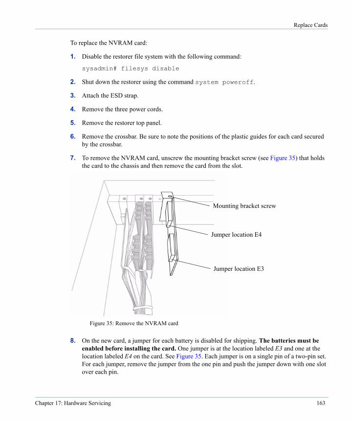
Replace Cards
To replace the NVRAM card:
1. Disable the restorer file system with the following command:
sysadmin# filesys disable
2. Shut down the restorer using the command system poweroff.
3. Attach the ESD strap.
4. Remove the three power cords.
5. Remove the restorer top panel.
6. Remove the crossbar. Be sure to note the positions of the plastic guides for each card secured by the crossbar.
7. To remove the NVRAM card, unscrew the mounting bracket screw (see Figure 35) that holds the card to the chassis and then remove the card from the slot.
8. On the new card, a jumper for each battery is disabled for shipping. The batteries must be enabled before installing the card. One jumper is at the location labeled E3 and one at the location labeled E4 on the card. See Figure 35. Each jumper is on a single pin of a two-pin set. For each jumper, remove the jumper from the one pin and push the jumper down with one slot over each pin.
Figure 35: Remove the NVRAM card
Jumper location E4
Jumper location E3
Mounting bracket screw
Chapter 17: Hardware Servicing 163
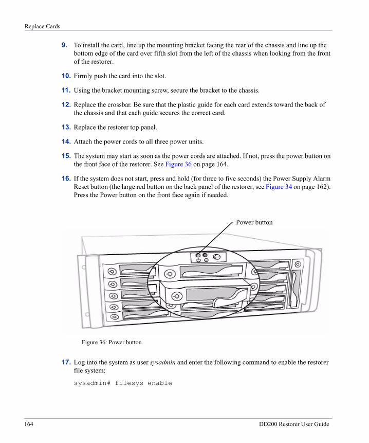
Replace Cards
9. To install the card, line up the mounting bracket facing the rear of the chassis and line up the bottom edge of the card over fifth slot from the left of the chassis when looking from the front of the restorer.
10. Firmly push the card into the slot.
11. Using the bracket mounting screw, secure the bracket to the chassis.
12. Replace the crossbar. Be sure that the plastic guide for each card extends toward the back of the chassis and that each guide secures the correct card.
13. Replace the restorer top panel.
14. Attach the power cords to all three power units.
15. The system may start as soon as the power cords are attached. If not, press the power button on the front face of the restorer. See Figure 36 on page 164.
16. If the system does not start, press and hold (for three to five seconds) the Power Supply Alarm Reset button (the large red button on the back panel of the restorer, see Figure 34 on page 162). Press the Power button on the front face again if needed.
17. Log into the system as user sysadmin and enter the following command to enable the restorer file system:
sysadmin# filesys enable
Figure 36: Power button
Power button
164 DD200 Restorer User Guide
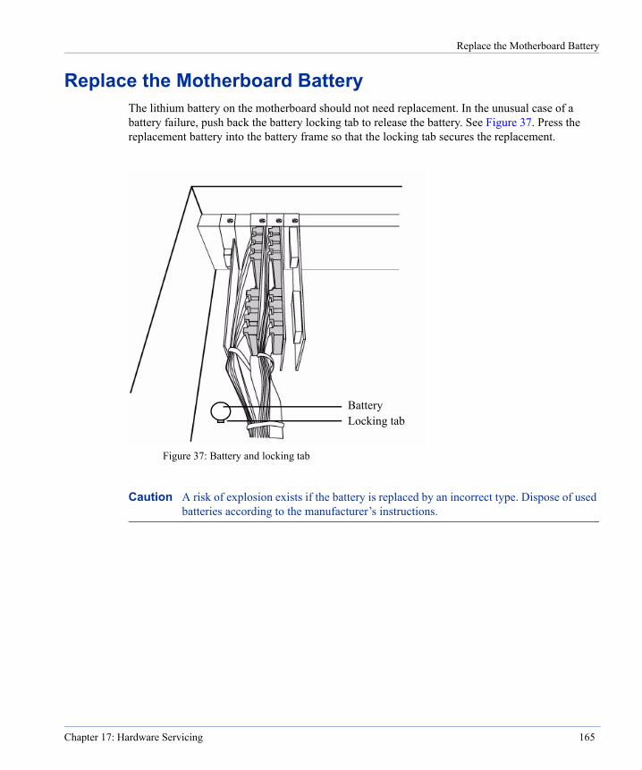
Replace the Motherboard Battery
Replace the Motherboard BatteryThe lithium battery on the motherboard should not need replacement. In the unusual case of a battery failure, push back the battery locking tab to release the battery. See Figure 37. Press the replacement battery into the battery frame so that the locking tab secures the replacement.
Caution A risk of explosion exists if the battery is replaced by an incorrect type. Dispose of used batteries according to the manufacturer’s instructions.
BatteryLocking tab
Figure 37: Battery and locking tab
Chapter 17: Hardware Servicing 165

Replace the Motherboard Battery
166 DD200 Restorer User Guide
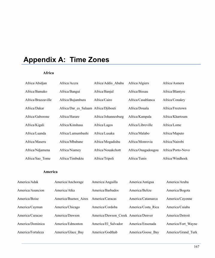
A
A
A
A
A
A
A
Appendix A: Time Zones
Africa
America
Africa/Abidjan Africa/Accra Africa/Addis_Ababa Africa/Algiers Africa/Asmera
Africa/Bamako Africa/Bangui Africa/Banjul Africa/Bissau Africa/Blantyre
Africa/Brazzaville Africa/Bujumbura Africa/Cairo Africa/Casablanca Africa/Conakry
Africa/Dakar Africa/Dar_es_Salaam Africa/Djibouti Africa/Douala Africa/Freetown
Africa/Gaborone Africa/Harare Africa/Johannesburg Africa/Kampala Africa/Khartoum
Africa/Kigali Africa/Kinshasa Africa/Lagos Africa/Libreville Africa/Lome
Africa/Luanda Africa/Lumumbashi Africa/Lusaka Africa/Malabo Africa/Maputo
Africa/Maseru Africa/Mbabane Africa/Mogadishu Africa/Monrovia Africa/Nairobi
Africa/Ndjamena Africa/Niamey Africa/Nouakchott Africa/Ouagadougou Africa/Porto-Novo
Africa/Sao_Tome Africa/Timbuktu Africa/Tripoli Africa/Tunis Africa/Windhoek
merica/Adak America/Anchorage America/Anguilla America/Antigua America/Aruba
merica/Asuncion America/Atka America/Barbados America/Belize America/Bogota
merica/Boise America/Buenos_Aires America/Caracas America/Catamarca America/Cayenne
merica/Cayman America/Chicago America/Cordoba America/Costa_Rica America/Cuiaba
merica/Curacao America/Dawson America/Dawson_Creek America/Denver America/Detroit
merica/Dominica America/Edmonton America/El_Salvador America/Ensenada America/Fort_Wayne
merica/Fortaleza America/Glace_Bay America/Godthab America/Goose_Bay America/Grand_Turk
167

A
A
A
A
A
A
A
A
A
A
A
A
A
A
Antarctica
Asia
merica/Grenada America/Guadeloupe America/Guatemala America/Guayaquil America/Guyana
merica/Halifax America/Havana America/Indiana America/Indianapolis America/Inuvik
merica/Iqaluit America/Jamaica America/Jujuy America/Juneau America/Knox_IN
merica/La_Paz America/Lima America/Los_Angeles America/Louisville America/Maceio
merica/Managua America/Manaus America/Martinique America/Mazatlan America/Mendoza
merica/Menominee America/Mexico_City America/Miquelon America/Montevideo America/Montreal
merica/Montserrat America/Nassau America/New_York America/Nipigon America/Nome
merica/Noronha America/Panama America/Pangnirtung America/Paramaribo America/Phoenix
merica/Port_of_Spain America/Port-au-Prince America/Porto_Acre America/Puerto_Rico America/Rainy_River
merica/Rankin_Inlet America/Regina America/Rosario America/Santiago America/Santo_Domingo
merica/Sao_Paulo America/Scoresbysund America/Shiprock America/St_Johns America/St_Kitts
merica/St_Lucia America/St_Thomas America/St_Vincent America/Swift_Current America/Tegucigalpa
merica/Thule America/Thunder_Bay America/Tijuana America/Tortola America/Vancouver
merica/Virgin America/Whitehorse America/Winnipeg America/Yakutat America/Yellowknife
Antarctica/Casey Antarctica/DumontDUrville Antarctica/Mawson Antarctica/McMurdo
Antarctica/Palmer Antarctica/South_Pole
Asia/Aden Asia/Alma-Ata Asia/Amman Asia/Anadyr Asia/Aqtau
Asia/Aqtobe Asia/Ashkhabad Asia/Baghdad Asia/Bahrain Asia/Baku
Asia/Bangkok Asia/Beirut Asia/Bishkek Asia/Brunei Asia/Calcutta
Asia/Chungking Asia/Colombo Asia/Dacca Asia/Damascus Asia/Dubai
Asia/Dushanbe Asia/Gaza Asia/Harbin Asia/Hong_Kong Asia/Irkutsk
Asia/Ishigaki Asia/Istanbul Asia/Jakarta Asia/Jayapura Asia/Jerusalem
168 DD200 Restorer User Guide

Atlantic
Australia
Brazil
Asia/Kabul Asia/Kamchatka Asia/Karachi Asia/Kashgar Asia/Katmandu
Asia/Krasnoyarsk Asia/Kuala_Lumpur Asia/Kuching Asia/Kuwait Asia/Macao
Asia/Magadan Asia/Manila Asia/Muscat Asia/Nicosia Asia/Novosibirsk
Asia/Omsk Asia/Phnom_Penh Asia/Pyongyang Asia/Qatar Asia/Rangoon
Asia/Riyadh Asia/Saigon Asia/Seoul Asia/Shanghai Asia/Singapore
Asia/Taipei Asia/Tashkent Asia/Tbilisi Asia/Tehran Asia/Tel_Aviv
Asia/Thimbu Asia/Tokyo Asia/Ujung_Pandang Asia/Ulan_Bator Asia/Urumqi
Asia/Vientiane Asia/Vladivostok Asia/Yakutsk Asia/Yekaterinburg Asia/Yerevan
Atlantic/Azores Atlantic/Bermuda Atlantic/Canary Atlantic/Cape_Verde Atlantic/Faeroe
Atlantic/Jan_Mayen Atlantic/Madeira Atlantic/Reykjavik Atlantic/South_Georgia Atlantic/St_Helena
Atlantic/Stanley
Australia/ACT Australia/Adelaide Australia/Brisbane Australia/Broken_Hill Australia/Canberra
Australia/Darwin Australia/Hobart Australia/LHI Australia/Lindeman Australia/Lord Howe
Australia/Melbourne Australia/NSW Australia/North Australia/Perth Australia/Queensland
Australia/South Australia/Sydney Australia/Tasmania Australia/Victoria Australia/West
Australia/Yancowinna
Brazil/Acre Brazil/DeNoronha Brazil/East Brazil/West
169
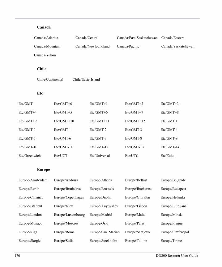
Canada
Chile
Etc
Europe
Canada/Atlantic Canada/Central Canada/East-Saskatchewan Canada/Eastern
Canada/Mountain Canada/Newfoundland Canada/Pacific Canada/Saskatchewan
Canada/Yukon
Chile/Continental Chile/EasterIsland
Etc/GMT Etc/GMT+0 Etc/GMT+1 Etc/GMT+2 Etc/GMT+3
Etc/GMT+4 Etc/GMT+5 Etc/GMT+6 Etc/GMT+7 Etc/GMT+8
Etc/GMT+9 Etc/GMT+10 Etc/GMT+11 Etc/GMT+12 Etc/GMT0
Etc/GMT-0 Etc/GMT-1 Etc/GMT-2 Etc/GMT-3 Etc/GMT-4
Etc/GMT-5 Etc/GMT-6 Etc/GMT-7 Etc/GMT-8 Etc/GMT-9
Etc/GMT-10 Etc/GMT-11 Etc/GMT-12 Etc/GMT-13 Etc/GMT-14
Etc/Greenwich Etc/UCT Etc/Universal Etc/UTC Etc/Zulu
Europe/Amsterdam Europe/Andorra Europe/Athens Europe/Belfast Europe/Belgrade
Europe/Berlin Europe/Bratislava Europe/Brussels Europe/Bucharest Europe/Budapest
Europe/Chisinau Europe/Copenhagen Europe/Dublin Europe/Gibraltar Europe/Helsinki
Europe/Istanbul Europe/Kiev Europe/Kuybyshev Europe/Lisbon Europe/Ljubljana
Europe/London Europe/Luxembourg Europe/Madrid Europe/Malta Europe/Minsk
Europe/Monaco Europe/Moscow Europe/Oslo Europe/Paris Europe/Prague
Europe/Riga Europe/Rome Europe/San_Marino Europe/Sarajevo Europe/Simferopol
Europe/Skopje Europe/Sofia Europe/Stockholm Europe/Tallinn Europe/Tirane
170 DD200 Restorer User Guide

GMT
Indian (Indian Ocean)
Mexico
Miscellaneous
Europe/Vaduz Europe/Vatican Europe/Vienna Europe/Vilnius Europe/Warsaw
Europe/Zagreb Europe/Zurich
GMT GMT+1 GMT+2 GMT+3 GMT+4
GMT+5 GMT+6 GMT+7 GMT+8 GMT+9
GMT+10 GMT+11 GMT+12 GMT+13 GMT-1
GMT-2 GMT-3 GMT-4 GMT-5 GMT-6
GMT-7 GMT-8 GMT-9 GMT-10 GMT-11
GMT-12
Indian/Antananarivo Indian/Chagos Indian/Christmas Indian/Cocos Indian/Comoro
Indian/Kerguelen Indian/Mahe Indian/Maldives Indian/Mauritius Indian/Mayotte
Indian/Reunion
Mexico/BajaNorte Mexico/BajaSur Mexico/General
Arctic/Longyearbyen CET CST6CDT Cuba EET
Egypt Eire EST EST5EDT Factory
GB GB-Eire Greenwich Hongkong HST
Iceland Iran Israel Jamaica Japan
Kwajalein Libya MET MST MST7MDT
Navajo NZ NZ-CHAT Poland Portugal
171
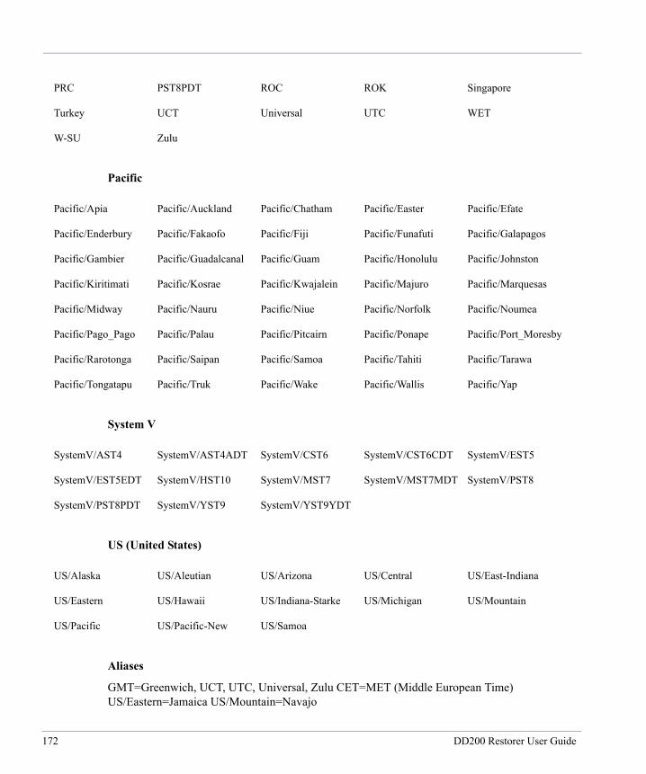
Pacific
System V
US (United States)
Aliases
GMT=Greenwich, UCT, UTC, Universal, Zulu CET=MET (Middle European Time) US/Eastern=Jamaica US/Mountain=Navajo
PRC PST8PDT ROC ROK Singapore
Turkey UCT Universal UTC WET
W-SU Zulu
Pacific/Apia Pacific/Auckland Pacific/Chatham Pacific/Easter Pacific/Efate
Pacific/Enderbury Pacific/Fakaofo Pacific/Fiji Pacific/Funafuti Pacific/Galapagos
Pacific/Gambier Pacific/Guadalcanal Pacific/Guam Pacific/Honolulu Pacific/Johnston
Pacific/Kiritimati Pacific/Kosrae Pacific/Kwajalein Pacific/Majuro Pacific/Marquesas
Pacific/Midway Pacific/Nauru Pacific/Niue Pacific/Norfolk Pacific/Noumea
Pacific/Pago_Pago Pacific/Palau Pacific/Pitcairn Pacific/Ponape Pacific/Port_Moresby
Pacific/Rarotonga Pacific/Saipan Pacific/Samoa Pacific/Tahiti Pacific/Tarawa
Pacific/Tongatapu Pacific/Truk Pacific/Wake Pacific/Wallis Pacific/Yap
SystemV/AST4 SystemV/AST4ADT SystemV/CST6 SystemV/CST6CDT SystemV/EST5
SystemV/EST5EDT SystemV/HST10 SystemV/MST7 SystemV/MST7MDT SystemV/PST8
SystemV/PST8PDT SystemV/YST9 SystemV/YST9YDT
US/Alaska US/Aleutian US/Arizona US/Central US/East-Indiana
US/Eastern US/Hawaii US/Indiana-Starke US/Michigan US/Mountain
US/Pacific US/Pacific-New US/Samoa
172 DD200 Restorer User Guide
Appendix B: Restorer Commands
adminaccessNAME adminaccess - Allow remote hosts to use FTP, TELNET, or SSH.
SYNOPSIS adminaccess add {ftp | telnet} host-list
adminaccess add ssh-keys
adminaccess del {ftp | telnet} host-list
adminaccess del ssh-keys lineno
adminaccess disable {ftp | telnet | ssh | all}
adminaccess enable {ftp | telnet | ssh | all}
adminaccess reset {ftp | telnet | ssh | all}
adminaccess reset ssh-keys
adminaccess show [ftp | telnet | ssh | all]
adminaccess show ssh-keys
DESCRIPTION The adminaccess command creates access control lists for the use of HTTP, FTP, TELNET, and SSH administrative protocols on the restorer. Every adminaccess operation is available to administrative users only.
OPERATIONS add Add hosts to a protocol. For multiple hosts, enter a list using commas or spaces or both. A host is a fully-qualified domain hostname, an IP address, an IP address subnet specification, or a wildcard hostname, such as *.yourcompany.com. An asterisk (*) means no restrictions.
A subnet specification is a subnet IP address, an IP address and netmask separated by a slash (/), or an IP address and number of bits separated by a slash (/). The number of bits is an integer between 8 and 30. An example of each specification is:
173

192.168.1.0/255.255.255.0 192.169.1.0/24
add ssh-keys Add an SSH public key, created on a remote machine, to the SSH authorized keys file on the restorer. Available to the sysadmin user only, the operation allows sysadmin to log in without giving a password. On the remote machine, create a public key using the ssh-keygen command. Use the key ~/.ssh/id_dsa.pub as generated on the remote machine by ssh-keygen as input to the add ssh-keys option. See the "EXAMPLES" section below for an example of the add ssh-keys option.
del Delete hosts from a protocol.
del ssh-keys Delete an SSH key from the key file. The lineno is a line number as displayed by the command adminaccess show ssh-keys.
disable Disable a service.
enable Enable a service.
reset Set the given access list to the factory defaults.
reset ssh-keys Remove the authorized SSH keys file from the restorer. After removing the file, every SSH connection needs password authentication. Available to the sysadmin user only.
show Display hosts from the given access list and status for the service.
show ssh-keys Display the SSH key file with a line number for each entry.
EXAMPLES To add the host srvr24 to the TELNET access list:
adminaccess add telnet srvr24.yourcompany.com
To add all hosts in a domain to the TELNET access list:
adminaccess add telnet *.yourcompany.com
To add an entire local subnet to the TELNET access list:
adminaccess add telnet 192.168.1.0/24
To add an SSH public key, create the public key on a remote machine, then from the remote machine, use a command similar to the following:
174 DD200 Restorer User Guide
ssh -l sysadmin rstr01 "adminaccess add \ ssh-keys < ~/.ssh/id_dsa.pub"
Restore Protection Manager 7 December 2004
175
alertsNAME alerts - Manage the alerts history file and email list.
SYNOPSIS alerts add email-list
alerts del email-list
alerts reset
alerts show alerts-list
alerts show all
alerts show {current | history | daily}
alerts test "reason" [email-addr]
DESCRIPTION The alerts command manages the alerts history file and who receives email notification for system alerts. Alerts happen whenever Restore Protection Manager discovers a problem with software or a monitored component.
OPERATIONS add Add email addresses to the list that receives system alert emails. The email-list is a list of email address that is comma-separated or space-separated or both. Administrative users only.
del Delete email addresses from the list. The email-list is a list of email address that is comma-separated or space-separated or both. Administrative users only.
reset Set the email list to the factory default of [email protected]. Administrative users only.
show alerts-list Display the alerts email list.
show all Display the alerts email list and the administrator email address.
show current Display alerts for all situations that have not been dealt with. For example, a message about a problem fan displays until the fan is replaced with a functional unit.
176 DD200 Restorer User Guide
show daily Display current alerts and the alerts events history for the last 24 hours. Use the up and down arrow keys to move through the log. Use the q key to exit. Enter a slash character (/) and a pattern to search for and highlight lines of particular interest.
show history Display the alerts events history file. The event history file includes one line (date and reason) for every system alert. Use the up and down arrow keys to move through the log. Use the q key to exit. Enter a slash character (/) and a pattern to search for and highlight lines of particular interest.
test "reason" Send an email with a message (reason) to all addresses on the alerts list or to one specified address. The reason is bracketed by double quotes. After adding addresses to the email list, always use this operation to test for any mailer problems.
EXAMPLE To add the email addresses [email protected] and [email protected] to the alerts email list:
alerts add [email protected], [email protected]
To test the alerts email list with the message Added a user test message:
alerts test "Added a user test message"
Restore Protection Manager 7 December 2004
177
aliasNAME alias - Create and display command aliases.
SYNOPSIS alias add name "command"
alias del name
alias reset
alias show
DESCRIPTION The alias command allows you to add, delete, and display command aliases for the Restore Protection Manager (restorer) command set. Each user can view and use only aliases for commands that are available at that user's permissions level. The default aliases and their corresponding restorer commands are:
date - system set date df - filesys show space hostname - net set hostname ifconfig - net config iostat - system show detailed-stats 2 netstat - net show stats nfsstat - nfs show stats passwd - user change password ping - net ping host-name poweroff - system poweroff reboot - system reboot sysstat [interval nsecs] - system show stats traceroute - route trace host-name uname - system show version uptime - system show uptime
OPERATIONS add Add a command alias. Give the name for the alias and then give the complete restorer command bracketed by double quotes ("..."). The new alias is available only for the user that adds the alias.
del Delete an alias by name.
reset Return to the default alias list, removing all user-added aliases.
178 DD200 Restorer User Guide
show Display all aliases and their command definitions. Note that the sysstat alias can include an interval option and value for the number of seconds between each display. The default interval is 2 seconds.
EXAMPLE The following command adds an alias named rely for the restorer command that displays disk reliability statistics
alias rely "disk show reliability-data"
Restore Protection Manager 9 July 2004
179
autosupportNAME autosupport - Manage the weekly system report.
SYNOPSIS autosupport add email-list
autosupport del email-list
autosupport display [brief | normal | verbose]
autosupport reset all
autosupport reset schedule
autosupport reset support-list
autosupport send [brief | normal | verbose][email-addr]
autosupport send debug [email-addr]
autosupport set schedule [daily | weekly | monthly | never] [day1[,day2,...]] time
autosupport show all
autosupport show history
autosupport show schedule
autosupport show support-list
DESCRIPTION The autosupport command manages when and at what frequency the system report is generated and who receives email notification. The system report gives complete system status and statistics on system use, and enters a line in the events history log file that the report was run.
OPERATIONS add Add email addresses to the list that receives system reports. The email-list is a list of email address that is comma-separated or space-separated or both. Administrative users only.
del Delete email addresses from the list. The email-list is a list of email address that is comma-separated or space-separated or both. Administrative users only.
display Runs and displays the normal system report, but does not send email. Each display level gives differing amounts of system information. Verbose gives the most information, including log file entries, used by Data Domain support personnel. Use the up
180 DD200 Restorer User Guide

and down arrow keys to move through the log. Use the q key to exit. Enter a slash character (/) and a pattern to search for and highlight lines of particular interest.
reset all Sets all autosupport parameters to the factory defaults. Administrative users only.
reset schedule Sets the weekly system report schedule to the default (sun 0300). Administrative users only.
reset support-list Sets the email list to the factory defaults. Administrative users only.
send Test-run the system report and email the results to all addresses on the autosupport list or to one specified address. After adding addresses to the email list, always use this operation to test for any mailer problems. Use brief for a smaller test email.
send debug Send output from the disk show debug command to the mailing list or to a given email address. Administrative users only.
set schedule Set the verbose system report to run at a given frequency and a given time. The schedule operation can specify a day (one or two numerals) or on a day of the week (three letters) at a specific time (0000). Administrative users only.
The daily and never periods do not take a day qualifier. The weekly period with a day qualifier or the day qualifier without weekly both run the command once a week. The never period turns off the system report.
The day qualifier is three letters (such as "mon" for Monday) when used with the weekly period and when used alone with the required time entry. The day qualifier is a day-of-the- month, from 1 to 31, when used with monthly.
time is 24-hour military time. 2400 is not a valid time. "mon 0000" is midnight between Sunday night and Monday morning.
show all Display all autosupport parameters.
181
show history Display the event history file, which includes the date for each autosupport report. Use the up and down arrow keys to move through the log. Use the q key to exit. Enter a slash character (/) and a pattern to search for and highlight lines of particular interest.
show schedule Displays the system report schedule.
show support-list Display the autosupport email list.
EXAMPLES To schedule the system report for every Tuesday at 3 p.m., use either of the following commands:
autosupport set schedule tue 1500 autosupport set schedule weekly tue 1500
To schedule the system report for 2 p.m. every Monday and Friday:
autosupport set schedule mon,fri 1400
To schedule the system report for 2 p.m. on the first and fifteenth of every month:
autosupport set schedule monthly 1,15 1400
Restore Protection Manager 13 October 2004
182 DD200 Restorer User Guide
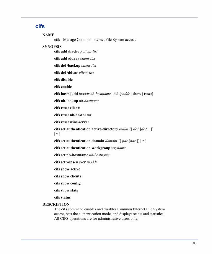
cifsNAME cifs - Manage Common Internet File System access.
SYNOPSIS cifs add /backup client-list
cifs add /ddvar client-list
cifs del /backup client-list
cifs del /ddvar client-list
cifs disable
cifs enable
cifs hosts [add ipaddr nb-hostname | del ipaddr | show | reset]
cifs nb-lookup nb-hostname
cifs reset clients
cifs reset nb-hostname
cifs reset wins-server
cifs set authentication active-directory realm {[ dc1 [dc2 ...]] | * }
cifs set authentication domain domain {[ pdc [bdc ]] | * }
cifs set authentication workgroup wg-name
cifs set nb-hostname nb-hostname
cifs set wins-server ipaddr
cifs show active
cifs show clients
cifs show config
cifs show stats
cifs status
DESCRIPTION The cifs command enables and disables Common Internet File System access, sets the authentication mode, and displays status and statistics. All CIFS operations are for administrative users only.
183

OPERATIONS add /backup Give CIFS backup accounts access to the backup file system through CIFS clients. The client list can be IP addresses or machine names. Wild cards are allowed. For each backup account, use the user add command to add the account to the DD200.
add /ddvar Give users administrative access through CIFS clients. The client list can be IP addresses or machine names. Wild cards are allowed. For each user account that needs administrative access, use the user add command to add the account to the DD200.
del /backup Remove access for CIFS backup accounts through clients. The client list can be IP addresses or machine names. Wild cards are allowed.
del /ddvar Remove administrative access for users through CIFS clients. The client list can be IP addresses or machine names. Wild cards are allowed.
disable Block CIFS clients from connecting to the DD200.
enable Allow CIFS clients to connect to the DD200.
hosts add Associate an IP address with a host name. The host name can be a fully-qualified domain name, or an alias and a fully-qualified domain name enclosed in double quotes. The entry is added to the lmhosts file.
hosts del Delete an IP address/host name entry from the lmhosts file.
hosts reset Remove IP address/host name entries from lmhosts.
hosts show Display IP address/host name entries from the lmhosts file.
nb-lookup Display the IP address for a given NetBIOS name. The CIFS feature must already be enabled.
reset clients Set the CIFS client list to the default, which is none.
184 DD200 Restorer User Guide

reset nb-hostname Set the NetBIOS hostname to the default, which is none.
reset wins-server Set the WINS server IP address to the default, which is none.
set authentication active-directory Set authentication to the active-directory mode. The realm must be a fully-qualified name. Data Domain recommends not specifying a domain controller. When not using a domain controller, first specify a WINS server. The DD200 must meet all active-directory requirments, such as a clock time that is no more than five minutes different than the domain controller. The domain controllers can be a list of email addresses that are comma-separated or space-separated or both.
set authentication domain Set authentication to the NT4 domain mode with a primary or primary and backup domain controller or all.
set authentication workgroup Set authentication to the workgroup mode.
set nb-hostname Set a NetBIOS host name for the DD200.
set wins-server Set the IP address for the WINS server that the DD200 uses to resolve NetBIOS names to IP addresses.
show active Display active CIFS clients.
show clients Display all allowed CIFS clients.
show config Display the CIFS configuration.
show stats Display CIFS statistics.
status Display whether or not CIFS is enabled.
Restore Protection Manager 17 December 2004
185

configNAME config - Manage the Restore Protection Manager (restorer) configuration settings.
SYNOPSIS config dump
config reset all
config reset { location | mailserver | timezone }
config set admin-email email-addr
config set admin-host host
config set location location
config set mailserver host
config set timezone zonename
config setup
config show { admin-email | admin-host | location | mailserver | timezone }
DESCRIPTION The config command allows a user to examine and modify configuration settings. Every config operation is available to administrative users only.
OPERATIONS dump Display the configuration settings.
reset all Set the configuration to the factory defaults.
reset location Set the location description to the default of empty.
reset mailserver Set the mailserver to the defaults of multicast.
reset timezone Set the timezone to the default of US/Pacific.
set admin-email Set an email address for alerts and autosupport emails.
set admin-host Set a system from which to administer the restorer.
186 DD200 Restorer User Guide

set location Set the system location description.
set mailserver Set the mail (SMTP) server.
set timezone Set the system timezone. Timezone names begin with Africa, America, Antarctica, Asia, Atlantic, Australia, Brazil, Canada, Chile, Europe, Indian, Mexico, Mideast, Pacific, and US.
setup Enter essential configuration parameters using an interactive script. At any prompt, enter a question mark (?) for details about anwering the prompt. After the first setup, or when using DHCP, each prompt that has a current value displays the value. Press Return to accept. Enter either host names or IP addresses where ever a prompt mentions a host. For any prompt that accepts a list, the list can be comma- or space-separated or both. At the end of the setup, you can save the configuration, leave the setup and erase any values, or go back to the beginning of the setup, in which case the values entered previously appear as the default at each prompt.
show admin-email Display the adminstrator email address.
show admin-host Display the names of the host systems from which one can administer the restorer.
show location Display the location description.
show mailserver Display the name of the mail (SMTP) server.
show timezone Display the system timezone.
EXAMPLE To save a copy of the configuration on a host machine from which you administer a restorer, use a command similar to the following. The command logs into restorer10, asks for a password, creates a file on your host machine, and then logs out of the restorer.
ssh -l sysadmin restorer10 config dump > mylocalcopy
To restore the saved configuration to a restorer and have it immediately become the current configuration, use a command similar to the following:
187

ssh -l sysadmin restorer10 < mylocalcopy
Restore Protection Manager 13 October 2004
188 DD200 Restorer User Guide
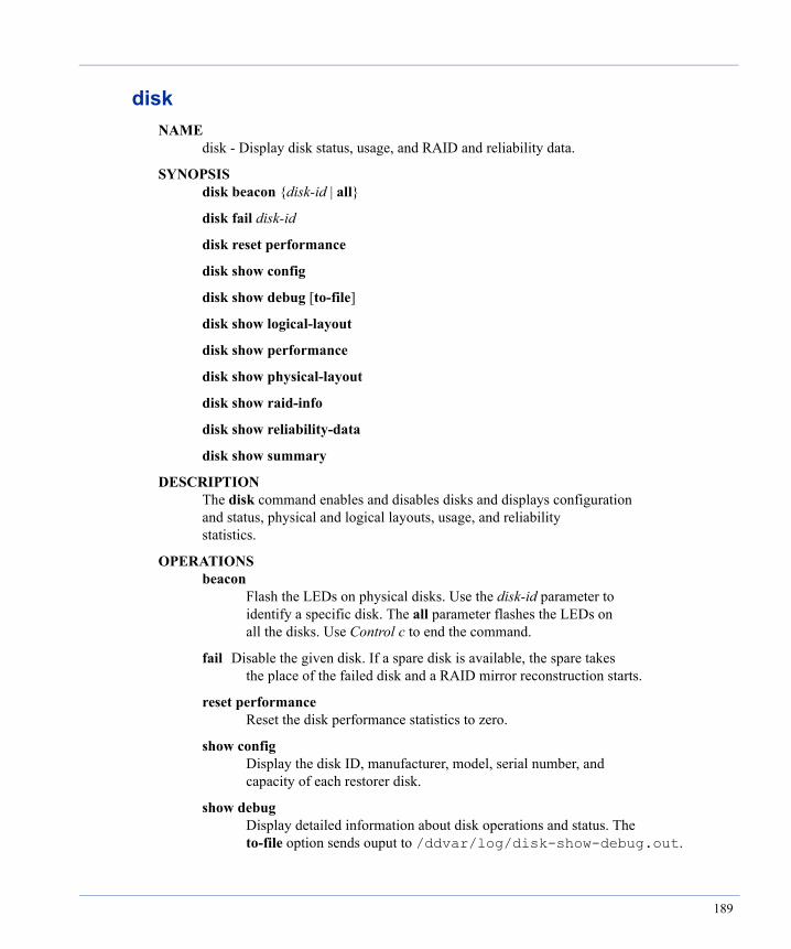
diskNAME disk - Display disk status, usage, and RAID and reliability data.
SYNOPSIS disk beacon {disk-id | all}
disk fail disk-id
disk reset performance
disk show config
disk show debug [to-file]
disk show logical-layout
disk show performance
disk show physical-layout
disk show raid-info
disk show reliability-data
disk show summary
DESCRIPTION The disk command enables and disables disks and displays configuration and status, physical and logical layouts, usage, and reliability statistics.
OPERATIONS beacon Flash the LEDs on physical disks. Use the disk-id parameter to identify a specific disk. The all parameter flashes the LEDs on all the disks. Use Control c to end the command.
fail Disable the given disk. If a spare disk is available, the spare takes the place of the failed disk and a RAID mirror reconstruction starts.
reset performance Reset the disk performance statistics to zero.
show config Display the disk ID, manufacturer, model, serial number, and capacity of each restorer disk.
show debug Display detailed information about disk operations and status. The to-file option sends ouput to /ddvar/log/disk-show-debug.out.
189
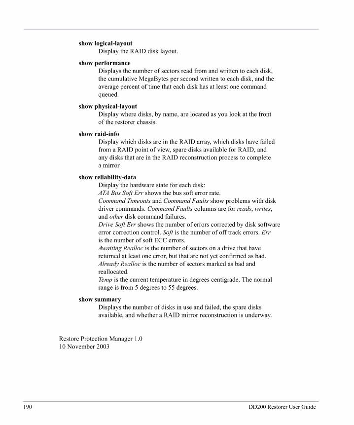
show logical-layout Display the RAID disk layout.
show performance Displays the number of sectors read from and written to each disk, the cumulative MegaBytes per second written to each disk, and the average percent of time that each disk has at least one command queued.
show physical-layout Display where disks, by name, are located as you look at the front of the restorer chassis.
show raid-info Display which disks are in the RAID array, which disks have failed from a RAID point of view, spare disks available for RAID, and any disks that are in the RAID reconstruction process to complete a mirror.
show reliability-data Display the hardware state for each disk: ATA Bus Soft Err shows the bus soft error rate. Command Timeouts and Command Faults show problems with disk driver commands. Command Faults columns are for reads, writes, and other disk command failures. Drive Soft Err shows the number of errors corrected by disk software error correction control. Soft is the number of off track errors. Err is the number of soft ECC errors. Awaiting Realloc is the number of sectors on a drive that have returned at least one error, but that are not yet confirmed as bad. Already Realloc is the number of sectors marked as bad and reallocated. Temp is the current temperature in degrees centigrade. The normal range is from 5 degrees to 55 degrees.
show summary Displays the number of disks in use and failed, the spare disks available, and whether a RAID mirror reconstruction is underway.
Restore Protection Manager 1.0 10 November 2003
190 DD200 Restorer User Guide
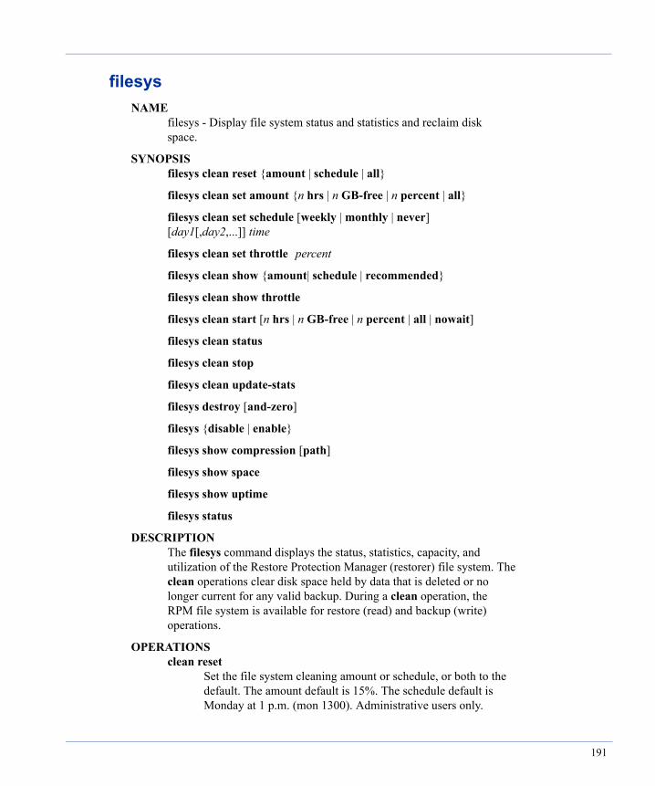
filesysNAME filesys - Display file system status and statistics and reclaim disk space.
SYNOPSIS filesys clean reset {amount | schedule | all}
filesys clean set amount {n hrs | n GB-free | n percent | all}
filesys clean set schedule [weekly | monthly | never] [day1[,day2,...]] time
filesys clean set throttle percent
filesys clean show {amount| schedule | recommended}
filesys clean show throttle
filesys clean start [n hrs | n GB-free | n percent | all | nowait]
filesys clean status
filesys clean stop
filesys clean update-stats
filesys destroy [and-zero]
filesys {disable | enable}
filesys show compression [path]
filesys show space
filesys show uptime
filesys status
DESCRIPTION The filesys command displays the status, statistics, capacity, and utilization of the Restore Protection Manager (restorer) file system. The clean operations clear disk space held by data that is deleted or no longer current for any valid backup. During a clean operation, the RPM file system is available for restore (read) and backup (write) operations.
OPERATIONS clean reset Set the file system cleaning amount or schedule, or both to the default. The amount default is 15%. The schedule default is Monday at 1 p.m. (mon 1300). Administrative users only.
191
clean set amount Set the default clean parameters to run the operation for n number of hours, until n percent of the file system is cleaned, to recover disk space until n number of gigabytes is available, or to clean the entire file system. The system default is 15%. Note that cleaning an entire full file system can take longer than ten hours. Administrative users only.
The clean operation can run for a given number of hours (hrs), until a given number of total gigabytes are free on the system (GB-free), or until a percentage of current data is cleaned (percent). You can set one, two, or all three options in one command. Whichever limit the operation reaches first stops the operation.
clean set schedule Set clean to run within a specified period on a given day (one or two numerals) or on a given day of the week (three letters) at a specific time (0000). Administrative users only.
The never period turns off the clean operation and does not take a day or time qualifier. The weekly period with a day qualifier or the day qualifier without weekly both run the command once a week.
The day qualifier is three letters (such as "mon" for Monday) when used with the weekly period and when used alone with the required time entry. The day qualifier is a day-of-the- month, from 1 to 31, when used with monthly.
time is 24-hour military time. 2400 is not a valid time. "mon 0000" is midnight between Sunday night and Monday morning.
clean set throttle Set clean to run using a given level of system resources when the restorer is busy. At a percentage of 0 (zero), cleaning runs very slowly or not at all. A percentage of 100 allows cleaning to take as much in the way of system resources as needed. The default is 100. When the restorer is not busy with backup or restore operations, cleaning runs at 100%. Administrative users only.
clean show {amount | schedule | recommended} Display the clean schedule or amount parameters or the estimated time needed for cleaning.
192 DD200 Restorer User Guide
clean show throttle Displays time estimates for running the filesys clean update-stats and filesys clean start all commands, and gives recommended times for a partial cleaning and for a full system cleaning.
clean start Start the clean operation. With no options, the operation uses the current parameters for the scheduled automatic cleaning. Note that cleaning an entire full file system can take longer than ten hours. Administrative users only.
The clean operation can run for a given number of hours (hrs), until a given number of total gigabytes are free on the system (GB-free), or until a percentage of current data is cleaned (percent). You can set one, two, or all three options in one command. Whichever limit the operation reaches first stops the operation.
The nowait option starts a clean operation with no warning prompts. Use the option carefully.
Note that any operation that shuts down the restorer file system, such as the filesys disable command, or that shuts down the restorer, such as a system poweroff or reboot, stops the clean operation. The clean does not restart when the system and file system restart. Either manually restart the clean or wait until the next scheduled start.
clean status Displays the status (active or not active) and progress of the clean operation.
clean stop Stop the clean operation. Administrative users only.
clean update-stats Updates the "If 100% cleaned" numbers in the output from the filesys show space command by running most sections of a full clean command. The update operation can take up to four hours. Administrative users only.
destroy Irrevocably deletes all data from and reinitializes the file system. Data is not recoverable after a destroy operation. The and-zero option writes zeros to the whole disk, which can take many hours. Administrative users only.
193
disable Turn off the restorer file system operations. Administrative users only.
enable Turn on the restorer file system operations. Administrative users only.
show compression Display the space used by and compression achieved for files, directories, and file systems. In general, the more often a backup is done for a particular file or file system, the higher the compression. Note that compression for a file or file system that is just rewritten may not display for up to ten minutes. If needed, use the command again after ten minutes to display the true compression. Other factors may influence the display. Call Data Domain Technical Support to analyse displays that seem incorrect.
show space Display the space used by and available to file system components. Values are in gigabytes to one decimal place. For example:
Resource Size GB Used GB Avail GB Use% ------------------------------------------------------ /ddvar 18 0 17 1% /backup (compressed data collection) Pre-compression - 944 - - Compressed Data 1226 7 1219 1% If 100% cleaned* 1226 6 1220 1% Meta Data 13 4 8 33% Index 1 0 1 11% Estimated compression ratio*: 94x * Estimate based on 07/28/03 cleaning
The /ddvar line gives a rough idea of the amount of space used by and available to the log files.
The Pre-compression line shows the amount of data (data sent to the restorer from backup servers) stored on the restorer.
194 DD200 Restorer User Guide

The Compressed section, Data line shows the size of total disk space available for data, actual physical space used, and physical space available for data storage. Warning messages go to the system log when the Use% figure reaches 90%, 95%, and 100%. At 100%, the restorer accepts no more data from backup servers.
The If 100% cleaned line is an estimate of actual physical space used and physical space available for data storage if you run the filesys clean operation to clean 100% of the file system. The estimate is based on the most recent clean operation.
The Meta Data line tracks space used for the internal file descriptions that the RPM creates for all stored files. Warning messages go to the system log when the Use% figure reaches 90%, 95%, and 100%. At 100%, the restorer accepts no more data from backup servers.
The Index line tracks space used for internal restorer operations. Warning messages go to the system log when the Use% figure reaches 90%, 95%, and 100%. At 100%, the restorer accepts no more data from backup servers.
The Estimated compression ratio line gives a rough idea of data compression efficiency. The estimate is based on the most recent clean operation and changes if the compressibility of data sent to the RPM changes. Note that the compression algorithm includes the metadata and index space as part of the total storage space.
show uptime Display the time that has passed since the file system was last enabled.
status Display the status of the file system. Some of the possible status messages are enabled and started or running, or disabled and halting or halted, or cleaning. If the clean process is running, the status of that process is included.
EXAMPLES To schedule the clean process for every Tuesday at 3 p.m., use either of the following commands:
filesys clean set schedule tue 1500 filesys clean set schedule weekly tue 1500
To schedule the clean process for 2 p.m. on the first and fifteenth of every month:
filesys set clean schedule monthly 1,15 1400
195
To manually run the clean operation until 100 gigabytes of space are available for data storage:
filesys clean start 100 GB-free
Restore Protection Manager 17 December 2004
196 DD200 Restorer User Guide

filesys cleanNAME filesys clean - Manage the file system process that recovers disk space held by expired data.
SYNOPSIS filesys clean reset {amount | schedule | all}
filesys clean set amount {n hrs | n GB-free | n percent | all}
filesys clean set schedule [weekly | monthly | never] [day1[,day2,...]] time
filesys clean set throttle percent
filesys clean show {amount | schedule| recommended}
filesys clean show throttle
filesys clean start [n hrs | n GB-free | n percent | all | nowait]
filesys clean status
filesys clean stop
filesys clean update-stats
DESCRIPTION The filesys clean operations clear disk space held by data that is deleted or no longer current for any valid backup. Use the filesys status command to check on the progress of clean operations.
OPERATIONS clean reset Set the file system cleaning amount or schedule, or both to the default. The amount default is 15%. The schedule default is Monday at 1 p.m. (mon 1300). Administrative users only.
clean set amount Set the default clean parameters to run the operation for n number of hours, until n percent of the file system is cleaned, to recover disk space until n number of gigabytes is available, or to clean the entire file system. The system default is 15%. Note that cleaning an entire full file system can take longer than ten hours. Administrative users only.
The clean operation can run for a given number of hours (hrs), until a given number of total gigabytes are free on the system (GB-free), or until a percentage of current data is cleaned
197
(percent). You can set one, two, or all three options in one command. Whichever limit the operation reaches first stops the operation.
clean set schedule Set clean to run within a specified period on a given day (one or two numerals) or on a given day of the week (three letters) at a specific time (0000). Administrative users only.
The never period turns off the clean operation and does not take a day or time qualifier. The weekly period with a day qualifier or the day qualifier without weekly both run the command once a week.
The day qualifier is three letters (such as "mon" for Monday) when used with the weekly period and when used alone with the required time entry. The day qualifier is a day-of-the- month, from 1 to 31, when used with monthly.
time is 24-hour military time. 2400 is not a valid time. "mon 0000" is midnight between Sunday night and Monday morning.
clean set throttle Set clean to run using a given level of system resources when the restorer is busy. At a percentage of 0 (zero), cleaning runs very slowly or not at all. A percentage of 100 allows cleaning to take as much in the way of system resources as needed. The default is 100. When the restorer is not busy with backup or restore operations, cleaning runs at 100%. Administrative users only.
clean show {amount | schedule| recommended} Display the clean schedule or amount parameters or the estimated time for cleaning.
clean show throttle Displays time estimates for running the filesys clean update-stats and filesys clean start all commands, and gives recommended times for a partial cleaning and for a full system cleaning.
clean start Start the clean operation. With no options, the operation uses the current parameters for the scheduled automatic cleaning. Note that cleaning an entire full file system can take longer than ten hours. Administrative users only.
198 DD200 Restorer User Guide
The clean operation can run for a given number of hours (hrs), until a given number of total gigabytes are free on the system (GB-free), or until a percentage of current data is cleaned (percent). You can set one, two, or all three options in one command. Whichever limit the operation reaches first stops the operation.
The nowait option starts a clean operation with no warning prompts. Use the option carefully.
Note that any operation that shuts down the restorer file system, such as the filesys disable command, or that shuts down the restorer, such as a system poweroff or reboot, stops the clean operation. The clean does not restart when the system and file system restart. Either manually restart the clean or wait until the next scheduled start.
clean status Displays the status (active or not active) and progress of the clean operation.
clean stop Stop the clean operation. Administrative users only.
clean update-stats Updates the "If 100% cleaned" numbers in the output from the filesys show space command by running most sections of a full clean command. The update operation can take up to four hours. Administrative users only.
EXAMPLES To schedule the clean process for every Tuesday at 3 p.m., use either of the following commands:
filesys set clean schedule tue 1500 filesys set clean schedule weekly tue 1500
To schedule the clean process for 2 p.m. on the first and fifteenth of every month:
filesys set clean schedule monthly 1,15 1400
Restore Protection Manager 17 December 2004
199
helpNAME help - Display help files for Restore Protection Manager (restorer) commands.
SYNOPSIS help [command-name] | [keyword]
DESCRIPTION The help command with no object displays a list of all restorer commands by name. For details about the syntax of a command, use help with a command name as the object. All restorer commands accept the tab key for completion of a unique entry.
The search feature displays every one-line command option from every command in the restorer command set that includes a match of a keyword. If the keyword is the same as a command name, the complete help page for the command displays.
Use the up and down arrow keys to move through a displayed command. Use the q key to exit. Enter a slash character (/) and a pattern to search for and highlight lines of particular interest.
EXAMPLE To list all of the restorer commands by name:
help
To show the syntax for the command adminaccess:
help adminaccess
To find all command options that include the keyword password:
help password ndmp add filer <filer> [ user <username> ][ password <password> ] Add or update auth token for <filer> user add <user> [ password <password> ] [ priv {admin|user} ] Add a new user user change password [<user>] Change the password for a user
Restore Protection Manager 24 September 2004
200 DD200 Restorer User Guide
licenseNAME license - Display and manage licenses.
SYNOPSIS license add license-key
license del license-key
license reset
license show
DESCRIPTION The license command lists current licenses on the DD200 and adds or deletes licenses. The licensed features are: Full for using all disk space on a DD200. Half for using half the disk space on a DD200. NFS for administration and backups from UNIX-based systems. CIFS for administration and backups from Windows systems. REPLICATION for replicating data from one restorer to another.
A DD200 with no licensed features always automatically boots up into the config setup command.
An add or delete of a feature takes effect immediately.
OPERATIONS add Add a feature license.
del Delete a feature license.
reset Reset (delete) all licenses.
show Display the current licenses and features.
EXAMPLES To add a license:
license add XEEC-EXDB-UJFF-BADF
To display current licenses:
license show 1 XEBD-EXDB-AXEE-FFDA NFS 2 XEEC-EXDB-UJFF-BADF CAPACITY-FULLSIZE You have 2 licenses
Restore Protection Manager 16 June 2004
201
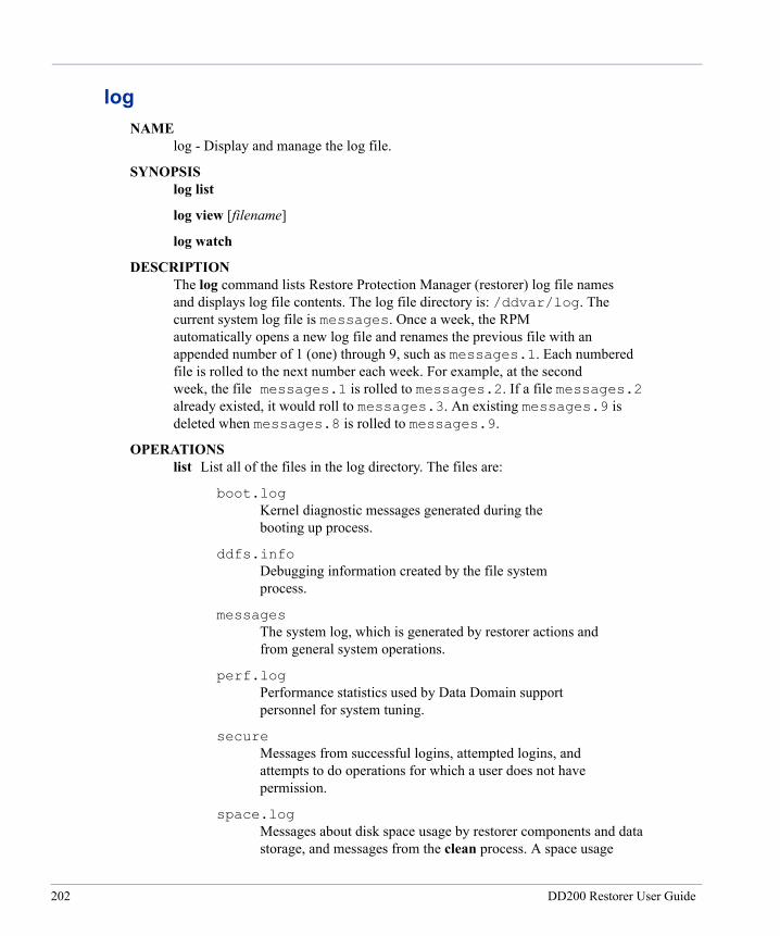
logNAME log - Display and manage the log file.
SYNOPSIS log list
log view [filename]
log watch
DESCRIPTION The log command lists Restore Protection Manager (restorer) log file names and displays log file contents. The log file directory is: /ddvar/log. The current system log file is messages. Once a week, the RPM automatically opens a new log file and renames the previous file with an appended number of 1 (one) through 9, such as messages.1. Each numbered file is rolled to the next number each week. For example, at the second week, the file messages.1 is rolled to messages.2. If a file messages.2 already existed, it would roll to messages.3. An existing messages.9 is deleted when messages.8 is rolled to messages.9.
OPERATIONS list List all of the files in the log directory. The files are:
boot.log Kernel diagnostic messages generated during the booting up process.
ddfs.info Debugging information created by the file system process.
messages The system log, which is generated by restorer actions and from general system operations.
perf.log Performance statistics used by Data Domain support personnel for system tuning.
secure Messages from successful logins, attempted logins, and attempts to do operations for which a user does not have permission.
space.log Messages about disk space usage by restorer components and data storage, and messages from the clean process. A space usage
202 DD200 Restorer User Guide

message is generated every hour. Each clean instance creates about 100 messages. The messages are in comma-separated- value format with tags that you can use to separate out the disk space or clean messages. You can use third-party software to analyse either set of messages. The tags are: CLEAN for data lines from clean operations. CLEAN_HEADER for lines that contain headers for the clean operations data lines. SPACE for disk space data lines. SPACE_HEADER for lines that contain headers for the disk space data lines.
view Display one screen of the most recent log entries. With no filename, the command displays entries from the current messages file. Use the up and down arrow keys to move through the log. Use the q key to exit. Enter a slash character (/) and a pattern to search for and highlight lines of particular interest.
watch Display the most recent log entries and see new entries as they are reported by the system. Use Control c to exit.
Restore Protection Manager 29 September 2003
203

ndmpNAME ndmp - Manages direct backup and restore operations between a filer and a restorer using the Network Data Management Protocol.
SYNOPSIS ndmp add filer filer_name user username [passwd password]
ndmp delete filer filer_name
ndmp get [incremental level_number] filer_name:src_tree dst_tree
ndmp put [partial subdir] src_file filer_name:dst_tree
ndmp reset filers
ndmp show filers
ndmp status
ndmp stop id-number
ndmp stop all
DESCRIPTION The ndmp command allows direct backup and restore operations between a Network Appliance filer (with the ndmpd daemon turned on) and a restorer. NDMP software on the restorer acts to provide Data Management Application functionality for the filer.
OPERATIONS add filer Make a filer available to the restorer. The username and password are for a user that can log in to the filer.
delete filer Remove a filer from the list available to the restorer.
get Backup data from a filer to a flat file on the restorer. The level_ number is an integer between 0 (zero) and 9. Using the command with no level is the same as level 0, which produces a full backup. Using any level greater than 0 backs up only changes since the latest backup of the same src_tree with a lower numbered level. The dst_tree argument must always begin with /backup.
put Restore data from within a flat backup file on a restorer to a filer. The partial option restores a particular directory or file. The src_file argument must always begin with /backup. For partial restores on some filers, dst_tree must end with subdir. For example: ndmp put partial myfile /backup/lv10 filer1: /vol/0/rest/myfile.
204 DD200 Restorer User Guide
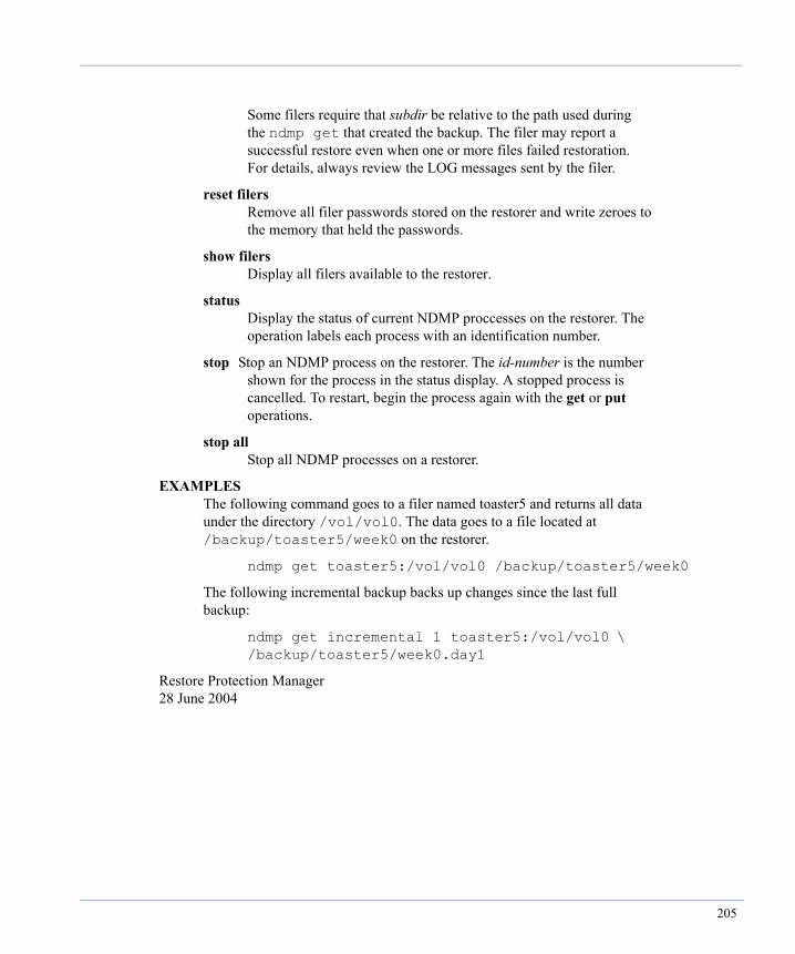
Some filers require that subdir be relative to the path used during the ndmp get that created the backup. The filer may report a successful restore even when one or more files failed restoration. For details, always review the LOG messages sent by the filer.
reset filers Remove all filer passwords stored on the restorer and write zeroes to the memory that held the passwords.
show filers Display all filers available to the restorer.
status Display the status of current NDMP proccesses on the restorer. The operation labels each process with an identification number.
stop Stop an NDMP process on the restorer. The id-number is the number shown for the process in the status display. A stopped process is cancelled. To restart, begin the process again with the get or put operations.
stop all Stop all NDMP processes on a restorer.
EXAMPLES The following command goes to a filer named toaster5 and returns all data under the directory /vol/vol0. The data goes to a file located at /backup/toaster5/week0 on the restorer.
ndmp get toaster5:/vol/vol0 /backup/toaster5/week0
The following incremental backup backs up changes since the last full backup:
ndmp get incremental 1 toaster5:/vol/vol0 \ /backup/toaster5/week0.day1
Restore Protection Manager 28 June 2004
205

netNAME net - Set up and display network parameters and display network status.
SYNOPSIS net config ifname [ipaddr][netmask mask][up | down] [dhcp {yes | no}][mtu {size | default}][autoneg][duplex {full | half}] [speed {10 | 100 | 1000}]
net disable ifname
net enable ifname
net hosts add ipaddr {host | "alias host"}
net hosts del ipaddr
net hosts reset
net hosts show
net ping host
net reset {[dns][domainname][hostname]}
net set dns ipaddr1[, ipaddr2[, ipaddr3]]
net set domainname name
net set hostname host
net show config [ifname]
net show {domainname | hostname | dns | all}
net show hardware
net show settings [ifname]
net show stats [all | interfaces | listening | route | statistics]
DESCRIPTION The net command sets up network parameters and Ethernet interface addresses and displays network information. The Ethernet interfaces on a restorer are: eth0 and eth1 with data transmission speeds of 10/100 Base-T, and eth2 and eth3 with a data transmission speed of 1000 Base-T (Gigabit).
OPERATIONS config Set network parameters for the Ethernet interface given as ifname. Administrative users only.
206 DD200 Restorer User Guide
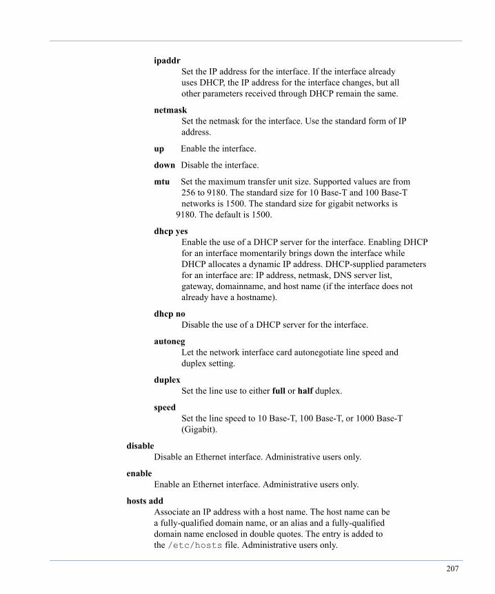
ipaddr Set the IP address for the interface. If the interface already uses DHCP, the IP address for the interface changes, but all other parameters received through DHCP remain the same.
netmask Set the netmask for the interface. Use the standard form of IP address.
up Enable the interface.
down Disable the interface.
mtu Set the maximum transfer unit size. Supported values are from 256 to 9180. The standard size for 10 Base-T and 100 Base-T networks is 1500. The standard size for gigabit networks is 9180. The default is 1500.
dhcp yes Enable the use of a DHCP server for the interface. Enabling DHCP for an interface momentarily brings down the interface while DHCP allocates a dynamic IP address. DHCP-supplied parameters for an interface are: IP address, netmask, DNS server list, gateway, domainname, and host name (if the interface does not already have a hostname).
dhcp no Disable the use of a DHCP server for the interface.
autoneg Let the network interface card autonegotiate line speed and duplex setting.
duplex Set the line use to either full or half duplex.
speed Set the line speed to 10 Base-T, 100 Base-T, or 1000 Base-T (Gigabit).
disable Disable an Ethernet interface. Administrative users only.
enable Enable an Ethernet interface. Administrative users only.
hosts add Associate an IP address with a host name. The host name can be a fully-qualified domain name, or an alias and a fully-qualified domain name enclosed in double quotes. The entry is added to the /etc/hosts file. Administrative users only.
207
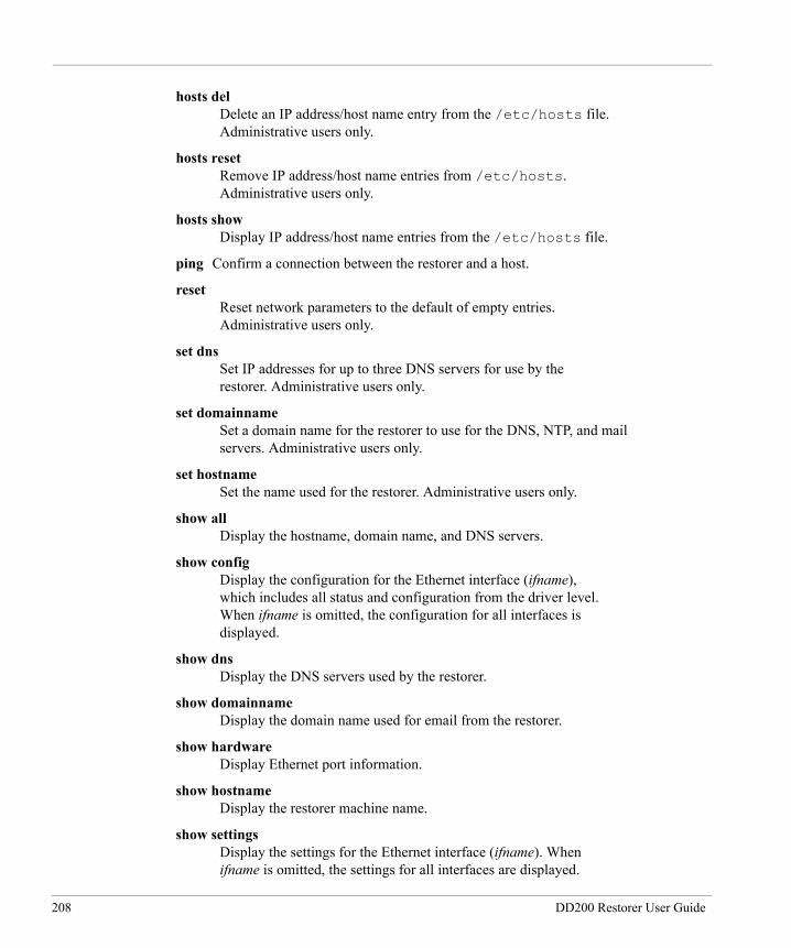
hosts del Delete an IP address/host name entry from the /etc/hosts file. Administrative users only.
hosts reset Remove IP address/host name entries from /etc/hosts. Administrative users only.
hosts show Display IP address/host name entries from the /etc/hosts file.
ping Confirm a connection between the restorer and a host.
reset Reset network parameters to the default of empty entries. Administrative users only.
set dns Set IP addresses for up to three DNS servers for use by the restorer. Administrative users only.
set domainname Set a domain name for the restorer to use for the DNS, NTP, and mail servers. Administrative users only.
set hostname Set the name used for the restorer. Administrative users only.
show all Display the hostname, domain name, and DNS servers.
show config Display the configuration for the Ethernet interface (ifname), which includes all status and configuration from the driver level. When ifname is omitted, the configuration for all interfaces is displayed.
show dns Display the DNS servers used by the restorer.
show domainname Display the domain name used for email from the restorer.
show hardware Display Ethernet port information.
show hostname Display the restorer machine name.
show settings Display the settings for the Ethernet interface (ifname). When ifname is omitted, the settings for all interfaces are displayed.
208 DD200 Restorer User Guide
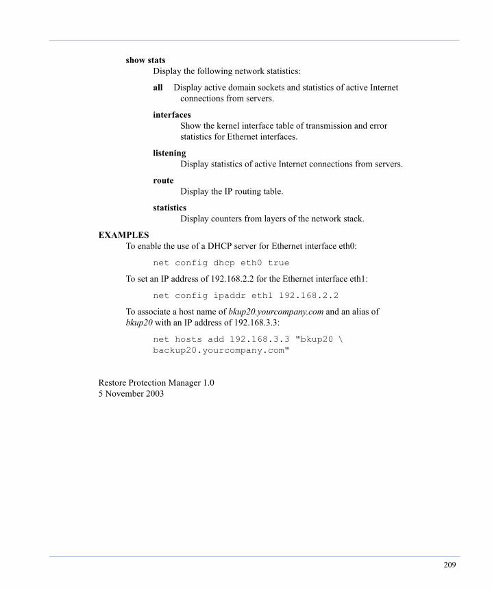
show stats Display the following network statistics:
all Display active domain sockets and statistics of active Internet connections from servers.
interfaces Show the kernel interface table of transmission and error statistics for Ethernet interfaces.
listening Display statistics of active Internet connections from servers.
route Display the IP routing table.
statistics Display counters from layers of the network stack.
EXAMPLES To enable the use of a DHCP server for Ethernet interface eth0:
net config dhcp eth0 true
To set an IP address of 192.168.2.2 for the Ethernet interface eth1:
net config ipaddr eth1 192.168.2.2
To associate a host name of bkup20.yourcompany.com and an alias of bkup20 with an IP address of 192.168.3.3:
net hosts add 192.168.3.3 "bkup20 \ backup20.yourcompany.com"
Restore Protection Manager 1.0 5 November 2003
209

net configNAME net config - Configure network parameters.
SYNOPSIS net config ifname [ipaddr][netmask mask][up | down] [dhcp {yes | no}][mtu size][autoneg][duplex {full | half}] [speed {10 | 100 | 1000}]
DESCRIPTION The net config operation sets up network parameters and Ethernet interface addresses. The Ethernet interfaces on a restorer are: eth0 with a data transmission speed of 10/100 Base-T, and eth1, eth2, and eth3 with a data transmission speed of 1000 Base-T (Gigabit).
OPERATIONS ifname Identifies the target interface: eth0, eth1, eth2, or eth3.
ipaddr Set the IP address for the interface. If the interface already uses DHCP, the IP address for the interface changes, but all other parameters received through DHCP remain the same.
netmask Set the netmask for the interface. Use the standard form of IP address.
up Enable the interface.
down Disable the interface.
dhcp Enable or disable DHCP for an interface. Enabling DHCP for an active interface momentarily brings down the interface while DHCP allocates a dynamic IP address. DHCP-supplied parameters for an interface are: IP address, netmask, DNS server list, gateway, domainname, and host name (if the interface does not already have a hostname).
mtu Set the maximum transfer unit size. Supported values are from 256 to 9180. The standard size for 10 Base-T and 100 Base-T networks is 1500. The standard size for gigabit networks is 9180.
autoneg Let the network interface card autonegotiate line speed and duplex settings. duplex Set the line use to either full or half duplex. speed Set the line speed to 10 Base-T, 100 Base-T, or 1000 Base-T
210 DD200 Restorer User Guide

(Gigabit). EXAMPLES To enable the use of a DHCP server for Ethernet interface eth0:
net config dhcp eth0 true
To set an IP address of 192.168.1.1 for the Ethernet interface eth1:
net config ipaddr eth1 192.168.1.1
Restore Protection Manager 5 November 2003
211

net setNAME net set - Set Remote Protection Manager (restorer) DNS servers, domain name, and host name.
SYNOPSIS net set dns ipaddr1[,ipaddr2[,ipaddr3]]
net set domainname name
net set hostname host
DESCRIPTION The net set operation sets DNS servers, domain name, and host name for use by a restorer.
OPERATIONS dns Set IP addresses for up to three DNS servers used by a restorer. The addresses can be separated by commas, spaces, or both.
domainname Set a domain name for the restorer to use for the DNS, NTP, and mail servers.
hostname Set the name used for the restorer.
EXAMPLES To give a restorer the domain name for the domain yourcompany.com:
net set domainname yourcompany.com
To set IP addresses of 192.168.1.1 and 192.168.1.1 for DNS servers:
net set dns 192.168.1.1, 192.168.1.1
Restore Protection Manager 1.0 5 November 2003
212 DD200 Restorer User Guide
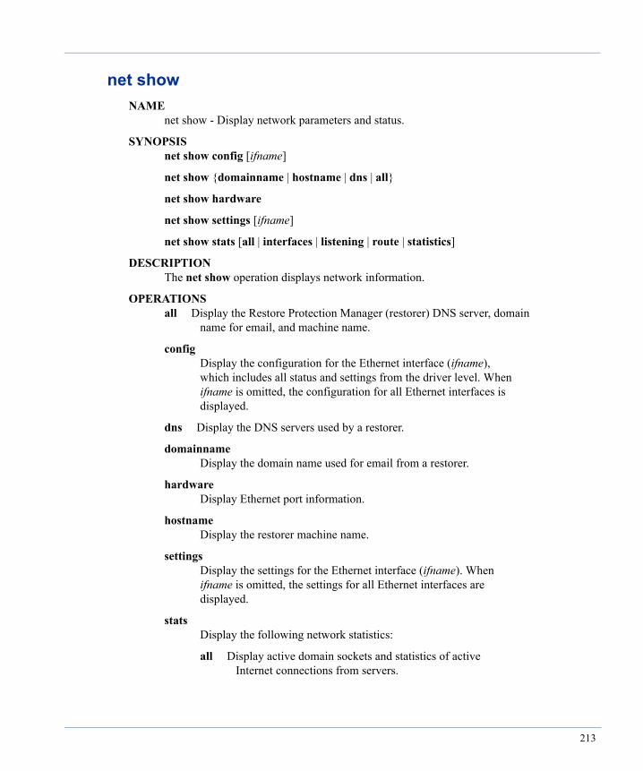
net showNAME net show - Display network parameters and status.
SYNOPSIS net show config [ifname]
net show {domainname | hostname | dns | all}
net show hardware
net show settings [ifname]
net show stats [all | interfaces | listening | route | statistics]
DESCRIPTION The net show operation displays network information.
OPERATIONS all Display the Restore Protection Manager (restorer) DNS server, domain name for email, and machine name.
config Display the configuration for the Ethernet interface (ifname), which includes all status and settings from the driver level. When ifname is omitted, the configuration for all Ethernet interfaces is displayed.
dns Display the DNS servers used by a restorer.
domainname Display the domain name used for email from a restorer.
hardware Display Ethernet port information.
hostname Display the restorer machine name.
settings Display the settings for the Ethernet interface (ifname). When ifname is omitted, the settings for all Ethernet interfaces are displayed.
stats Display the following network statistics:
all Display active domain sockets and statistics of active Internet connections from servers.
213
interfaces Show the kernel interface table of transmission and error statistics for Ethernet interfaces.
listening Display statistics of active Internet connections from servers
route Display the IP routing table.
statistics Display counters from layers of the network stack.
Restore Protection Manager 1.0 5 November 2003
214 DD200 Restorer User Guide
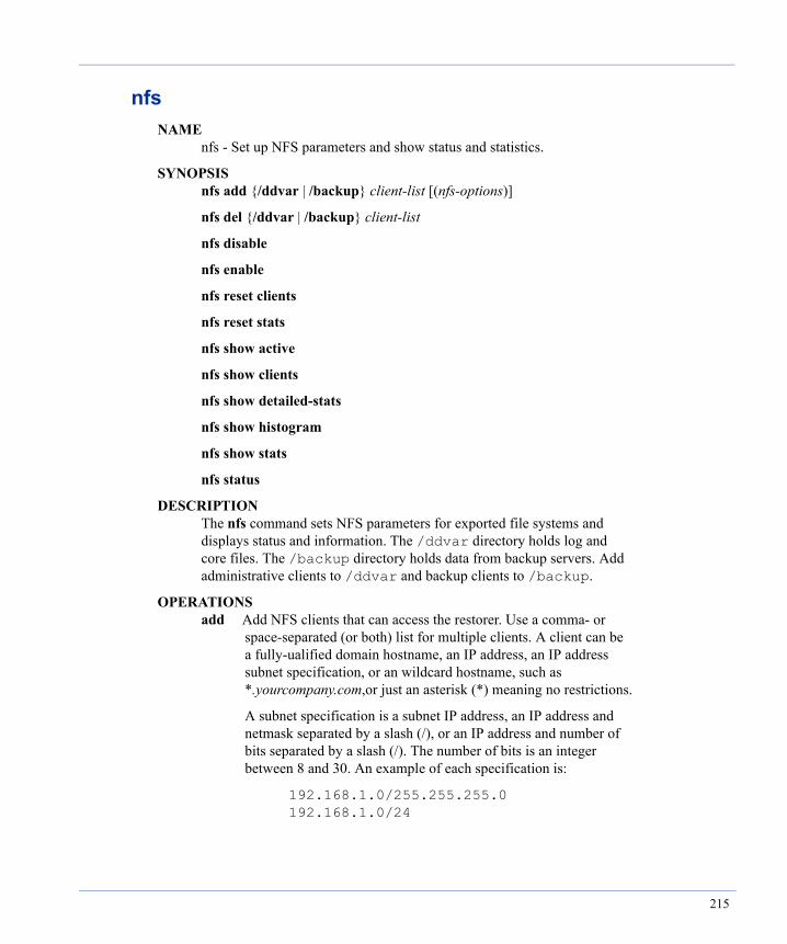
nfsNAME nfs - Set up NFS parameters and show status and statistics.
SYNOPSIS nfs add {/ddvar | /backup} client-list [(nfs-options)]
nfs del {/ddvar | /backup} client-list
nfs disable
nfs enable
nfs reset clients
nfs reset stats
nfs show active
nfs show clients
nfs show detailed-stats
nfs show histogram
nfs show stats
nfs status
DESCRIPTION The nfs command sets NFS parameters for exported file systems and displays status and information. The /ddvar directory holds log and core files. The /backup directory holds data from backup servers. Add administrative clients to /ddvar and backup clients to /backup.
OPERATIONS add Add NFS clients that can access the restorer. Use a comma- or space-separated (or both) list for multiple clients. A client can be a fully-ualified domain hostname, an IP address, an IP address subnet specification, or an wildcard hostname, such as *.yourcompany.com,or just an asterisk (*) meaning no restrictions.
A subnet specification is a subnet IP address, an IP address and netmask separated by a slash (/), or an IP address and number of bits separated by a slash (/). The number of bits is an integer between 8 and 30. An example of each specification is:
192.168.1.0/255.255.255.0 192.168.1.0/24
215

The nfs-options are a comma-separated or space-separated (or both) list bounded by parentheses. With no options specified, the default options are rw, root_squash, no_all_squash, and secure. The following options are allowed:
ro Read only permission.
rw Read and write permissions.
root_squash Map requests from uid/gid 0 to the anonymous uid/gid.
no_root_squash Turn off root squashing.
all_squash Map all user requests to the anonymous uid/gid.
no_all_squash Turn off the mapping of all user requests to the anonymous uid/gid.
secure Require that all requests originate on an Internet port that is less than IPPORT_RESERVED (1024).
insecure Turns off the secure option.
anonuid=id Set an explicit uid for the anonymous account. The id is an integer bounded from -65635 to 65635.
anongid=id Set an explicit gid for the anonymous account. The id is an integer bounded from -65635 to 65635.
del Remove client access to the /ddvar or /backup file system.
disable Do not allow NFS clients to connect.
enable Allow NFS clients to connect.
reset clients Set the client list to the default. Available to administrative users only.
reset stats Clear the NFS statistics.
216 DD200 Restorer User Guide
show active Display active NFS clients.
show clients Display all allowed NFS clients.
show detailed-stats Display NFS cache entries and status for troubleshooting.
show histogram Display NFS operations in a histogram.
show stats Display NFS stats.
status Display whether or not NFS is enabled.
EXAMPLES To add any host on the local network 192.168.1.0 with read/write access to /ddvar and the secure option:
nfs add /ddvar 192.168.1.0/24 (rw,secure)
To add all hosts to /backup with the default options of rw, no_root_squash, no_all_squash, and secure:
nfs add /backup *
Restore Protection Manager 5 October 2004
217
nfs showNAME nfs show - Show NFS status and statistics.
SYNOPSIS nfs show active
nfs show clients
nfs show detailed-stats
nfs show histogram
nfs show stats
DESCRIPTION The nfs show operation displays detailed NFS information.
OPERATIONS active Display active NFS clients.
clients Display all allowed NFS clients.
detailed-stats Display NFS cache entries and status for troubleshooting.
histogram Display NFS operations in a histogram.
stats Display NFS stats.
Restore Protection Manager 18 May 2004
218 DD200 Restorer User Guide
ntpNAME ntp - Allows synchronizing a restorer with NTP time servers and managing the NTP service.
SYNOPSIS ntp add timeserver server_name
ntp del timeserver server_name
ntp disable
ntp enable
ntp reset
ntp reset timeservers
ntp show config
ntp status
DESCRIPTION The ntp command allows giving a restorer access to one or more time servers. The default system settings are that the NTP service on a restorer is enabled in multicast mode.
OPERATIONS add timeserver Add a remote time server to the NTP list.
delete timeserver Remove a time server from the NTP list.
disable Stop the NTP service on the restorer.
enable Start the NTP service on the restorer.
reset Reset the local NTP service to the defaults of mulitcast and enbled.
reset timeserver Reset the time server list to the default of multicast mode.
show config Display the NTP enabled/disabled setting and the time server list.
status Display the NTP service status, time, and last synchronization time.
219
EXAMPLE The following command gives the time server srvr26.company.com as a time server for the restorer to use for synchronization.
ntp add timeserver srvr26.company.com
Restore Protection Manager 24 August 2004
220 DD200 Restorer User Guide
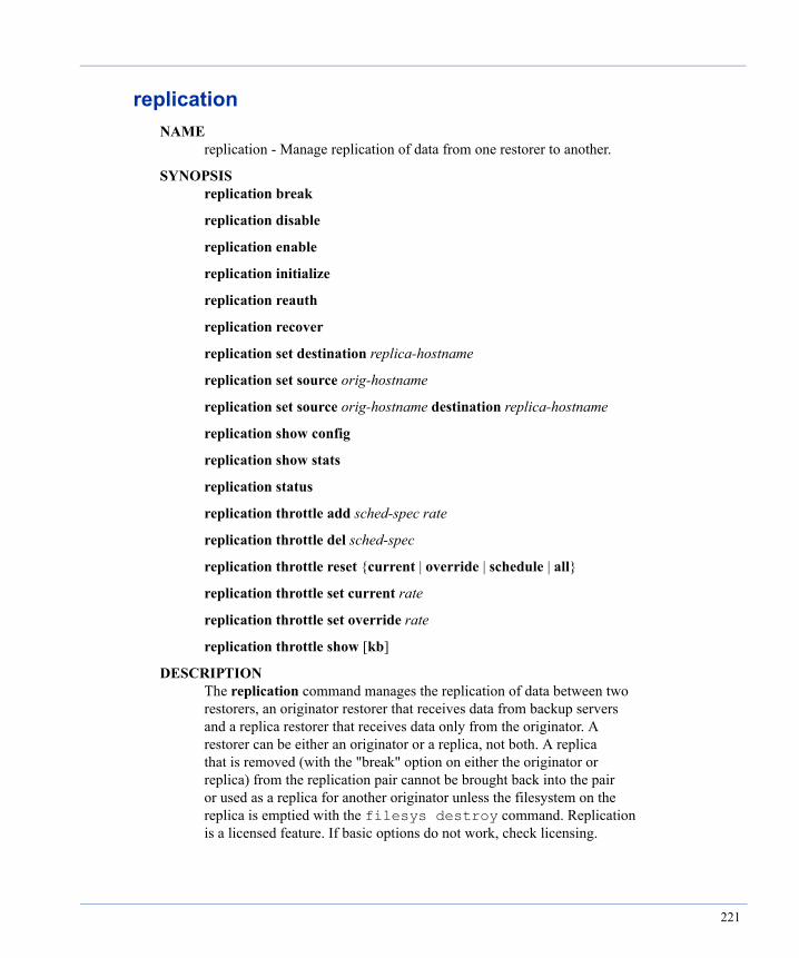
replicationNAME replication - Manage replication of data from one restorer to another.
SYNOPSIS replication break
replication disable
replication enable
replication initialize
replication reauth
replication recover
replication set destination replica-hostname
replication set source orig-hostname
replication set source orig-hostname destination replica-hostname
replication show config
replication show stats
replication status
replication throttle add sched-spec rate
replication throttle del sched-spec
replication throttle reset {current | override | schedule | all}
replication throttle set current rate
replication throttle set override rate
replication throttle show [kb]
DESCRIPTION The replication command manages the replication of data between two restorers, an originator restorer that receives data from backup servers and a replica restorer that receives data only from the originator. A restorer can be either an originator or a replica, not both. A replica that is removed (with the "break" option on either the originator or replica) from the replication pair cannot be brought back into the pair or used as a replica for another originator unless the filesystem on the replica is emptied with the filesys destroy command. Replication is a licensed feature. If basic options do not work, check licensing.
221
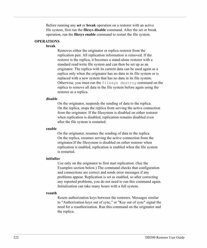
Before running any set or break operation on a restorer with an active file system, first run the filesys disable command. After the set or break operation, run the filesys enable command to restart the file system.
OPERATIONS break Removes either the originator or replica restorer from the replication pair. All replication information is removed. If the restorer is the replica, it becomes a stand-alone restorer with a standard read/write file system and can then be set up as an originator. The replica with its current data can be used again as a replica only when the originator has no data in its file system or is replaced with a new system that has no data in its file system. Otherwise, you must run the filesys destroy command on the replica to remove all data in the file system before again using the restorer as a replica.
disable On the originator, suspends the sending of data to the replica. On the replica, stops the replica from serving the active connection from the originator. If the filesystem is disabled on either restorer when replication is disabled, replication remains disabled even after the file system is restarted.
enable On the originator, resumes the sending of data to the replica. On the replica, resumes serving the active connection from the originator.If the filesystem is disabled on either restorer when replication is enabled, replication is enabled when the file system is restarted.
initialize Use only on the originator to first start replication. (See the Examples section below.) The command checks that configuration and connections are correct and sends error messages if any problems appear. Replication is set as enabled, so after correcting any reported problems, you do not need to run this command again. Initialization can take many hours with a full system.
reauth Resets authorization keys between the restorers. Messages similar to "Authorization keys out of sync," or "Key out of sync" signal the need for a reauthorization. Run this command on the originator and the replica.
222 DD200 Restorer User Guide
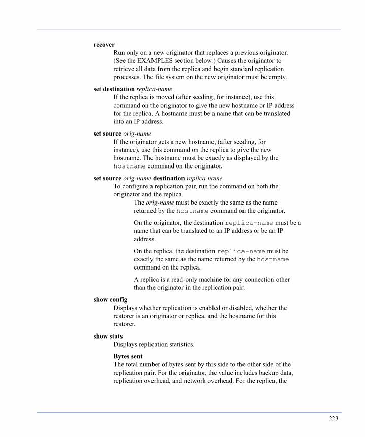
recover Run only on a new originator that replaces a previous originator. (See the EXAMPLES section below.) Causes the originator to retrieve all data from the replica and begin standard replication processes. The file system on the new originator must be empty.
set destination replica-name If the replica is moved (after seeding, for instance), use this command on the originator to give the new hostname or IP address for the replica. A hostname must be a name that can be translated into an IP address.
set source orig-name If the originator gets a new hostname, (after seeding, for instance), use this command on the replica to give the new hostname. The hostname must be exactly as displayed by the hostname command on the originator.
set source orig-name destination replica-name To configure a replication pair, run the command on both the originator and the replica. The orig-name must be exactly the same as the name returned by the hostname command on the originator.
On the originator, the destination replica-name must be a name that can be translated to an IP address or be an IP address.
On the replica, the destination replica-name must be exactly the same as the name returned by the hostname command on the replica.
A replica is a read-only machine for any connection other than the originator in the replication pair.
show config Displays whether replication is enabled or disabled, whether the restorer is an originator or replica, and the hostname for this restorer.
show stats Displays replication statistics.
Bytes sent The total number of bytes sent by this side to the other side of the replication pair. For the originator, the value includes backup data, replication overhead, and network overhead. For the replica, the
223

value includes replication overhead and network overhead. Use the value (and the next value) to estimate network traffic generated by replication.
Bytes received The total number of bytes received by this side from the other side of the replication pair. For the replica, the value includes backup data, replication overhead, and network overhead. For the originator, the value includes replication overhead and network overhead. Use the value (and the previous value) to estimate network traffic generated by replication.
Virtual bytes replicated The total number of bytes of backup data (before compression) replicated since the last time the restorer file system was enabled.
Replica received stamp The date and time when the most recent records were received.
Replica processed stamp The date and time when the most recent records were processed.
Replica records remaining The number of file records received by the replica and not yet processed.
Originator records remaining The number of file records created by the originator and not yet sent to the replica.
Compressed data remaining New data on the originator that is not yet processed into file records for sending to the replica.
status Displays replication configuration information and the status of replication operations.
Mode The role of the restorer in the replication pair: originator or replica.
Partner The hostname of the other restorer in the replication pair.
Enabled The enabled/disabled state of replication on this restorer.
Connection The most recent connection (or disconnect) date and time for the replication pair.
224 DD200 Restorer User Guide

State Whether or not replication was started afer the initial configuration or the percentage completed by the initialization process if that process is still in progress.
Replica lag Time that the replica needs to become synchronized with the originator in hours and minutes. A generic message of "Less than 5 minutes" appears if the replica is either nearly caught up with data from the originator or if the replica is caught up and synchronized and the originator is not sending new data.
throttle add sched-spec rate Add a scheduled time to change the rate of network bandwidth used by replication. The sched-spec must include one or more three- letter days of the week (such as mon, tue, or wed) or the word daily to set the schedule every day of the week, and a time of day in 24 hour military time. The rate must include a number or the word unlimited. As an option, the number can include a tag for bits or bytes per second. With no bits or bytes specified, the default rate is bits per second. In the rate variable:
bps or b equals raw bits per second Kbps, Kb, or K equals 1024 bits per second Bps or B equals bytes per second KBps or KB equals 1024 bytes per second
For example, the following command limits replication to 20 kilobytes per second starting on Mondays and Thursdays at 6:00 a.m.
replication throttle add mon thu 0600 20KB
Replication runs at the given rate until another scheduled change or until other replication throttle commands force a change. The default rate with no scheduled changes is unlimited.
The add command may change the current rate. For example, assume that on Monday at Noon, the current rate is 20 KB, and the schedule that set the current rate started on mon 0600. If you now add a scheduled change for Monday at 100 at a rate of 30 KB (mon 1100 30KB), the change takes place immediately.
throttle del sched-spec Remove one or more throttle schedule entries. The sched-spec must include one or more three-letter days of the week (such as mon, tue, or wed) or the word daily to delete all entries for the given time, and a time of day in 24 hour military time.
225
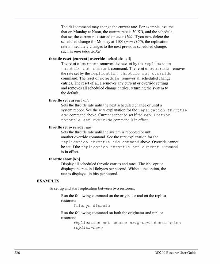
The del command may change the current rate. For example, assume that on Monday at Noon, the current rate is 30 KB, and the schedule that set the current rate started on mon 1100. If you now delete the scheduled change for Monday at 1100 (mon 1100), the replication rate immediately changes to the next previous scheduled change, such as mon 0600 20KB.
throttle reset {current | override | schedule | all} The reset of current removes the rate set by the replication throttle set current command. The reset of override removes the rate set by the replication throttle set override command. The reset of schedule removes all scheduled change entries. The reset of all removes any current or override settings and removes all scheduled change entries, returning the system to the default.
throttle set current rate Sets the throttle rate until the next scheduled change or until a system reboot. See the rate explanation for the replication throttle add command above. Current cannot be set if the replication throttle set override command is in effect.
throttle set override rate Sets the throttle rate until the system is rebooted or until another override command. See the rate explanation for the replication throttle add command above. Override cannot be set if the replication throttle set current command is in effect.
throttle show [kb] Display all scheduled throttle entries and rates. The kb option displays the rate in kilobytes per second. Without the option, the rate is displayed in bits per second.
EXAMPLES
To set up and start replication between two restorers:
Run the following command on the originator and on the replica restorers: filesys disable
Run the following command on both the originator and replica restorers: replication set source orig-name destination replica-name
226 DD200 Restorer User Guide
Run the following command on the originator and on the replica: filesys enable
Run the following command on the originator: replication initialize
To integrate a new originator that replaces a previous originator.
If the new originator has any data in its file system, run the following command to clear all data from the file system: filesys destroy
Run the following command on the new originator and on the replica: filesys disable
Run the following command on the replica. replication reauth
Run the following command on the new originator and on the replica: replication set source orig-name destination replica-name
Run the following command on the new originator and on the replica: filesys enable
Run the following command on the new originator to seed the new originator with data from the replica. After the command finishes, the originator is ready to receive new data and the replication is enabled. You do not need to do anything else to start replication: replication recover
To integrate a new replica restorer that replaces a previous replica:
If the new replica has any data in its file system, run the following command to clear all data from the file system: filesys destroy
Run the following command on the originator and on the new replica: filesys disable
Run the following command on the originator to remove all configuration information about the previous replica: replication reauth
227
Run the following command on the originator and on the new replica to configure replication: replication set source orig-name destination replica-name
Run the following command on the originator and on the new replica: filesys enable
Run the following command on the orginator to seed the new replica with data: replication initialize
14 January 2005
228 DD200 Restorer User Guide
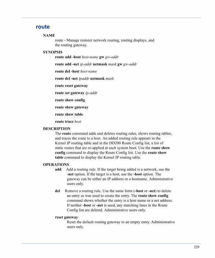
routeNAME route - Manage restorer network routing, routing displays, and the routing gateway.
SYNOPSIS route add -host host-name gw gw-addr
route add -net ip-addr netmask mask gw gw-addr
route del -host host-name
route del -net ipaddr netmask mask
route reset gateway
route set gateway ip-addr
route show config
route show gateway
route show table
route trace host
DESCRIPTION The route command adds and deletes routing rules, shows routing tables, and traces the route to a host. An added routing rule appears in the Kernel IP routing table and in the DD200 Route Config list, a list of static routes that are re-applied at each system boot. Use the route show config command to display the Route Config list. Use the route show table command to display the Kernel IP routing table.
OPERATIONS add Add a routing rule. If the target being added is a network, use the -net option. If the target is a host, use the -host option. The gateway can be either an IP address or a hostname. Administrative users only.
del Remove a routing rule. Use the same form (-host or -net) to delete an entry as was used to create the entry. The route show config command shows whether the entry is a host name or a net address. If neither -host or -net is used, any matching lines in the Route Config list are deleted. Administrative users only.
reset gateway Reset the default routing gateway to an empty entry. Administrative users only.
229

set gateway Set a default gateway. Administrative users only.
show config Display the Route Config list of configured static routes. Administrative users only.
show gateway Display the default routing gateway.
show table Display the Kernel IP routing table. Administrative users only.
trace Display a traceroute to the named host.
EXAMPLES To add a route with a route specification of 192.168.1.x, a netmask, and a gateway of srvr12:
route add -net 192.168.1.0 netmask 255.255.255.0 gw srvr12
To delete a route with a route specification of 192.168.1.x and a netmask of 255.255.255.0:
route del -net 192.168.1.0 netmask 255.255.255.0
To add a route for host user24 with a gateway of srvr12:
route add -host user24 gw srvr12
To give a default gateway when no other route matches:
route set gateway 192.168.10.1
Restore Protection Manager 1.0 12 November 2003
230 DD200 Restorer User Guide
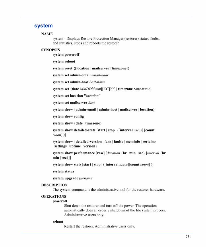
systemNAME system - Displays Restore Protection Manager (restorer) status, faults, and statistics, stops and reboots the restorer.
SYNOPSIS system poweroff
system reboot
system reset {[location][mailserver][timezone]}
system set admin-email email-addr
system set admin-host host-name
system set {date MMDDhhmm[[CC]YY] | timezone zone-name}
system set location "location"
system set mailserver host
system show {admin-email | admin-host | mailserver | location}
system show config
system show {date | timezone}
system show detailed-stats [start | stop | ([interval nsecs] [count count] )]
system show {detailed-version | fans | faults | meminfo | serialno | settings | uptime | version}
system show performance [raw] [duration {hr | min | sec} [interval {hr | min | sec}]]
system show stats [start | stop | ([interval nsecs][count count] )]
system status
system upgrade filename
DESCRIPTION The system command is the administrative tool for the restorer hardware.
OPERATIONS poweroff Shut down the restorer and turn off the power. The operation automatically does an orderly shutdown of the file system process. Administrative users only.
reboot Restart the restorer. Administrative users only.
231

reset Set the system location, mailserver, or timezone to the default value. The default is a null entry for each parameter except for timezone, which defaults to Universal (GMT). Administrative users only.
set admin-email Set an address for email messages from the alerts and autosupport utilities. The system needs one and only one admin-email address. Use the autosupport and alerts commands to add other email addresses.
set admin-host Set the machine from which you can log into the DD200 to see system logs and use system commands. The host name can be a simple host name, a fully-qualified host name, or an IP address.
set date Set the system clock and date. Administrative users only. The entry components are two places for month (MM of 01 through 12), two places for day of the month (DD 01 through 31), two places for hours (hh or 00 through 23), two places for minutes (mm of 00 through 59), and optionally, two places for century (CC) and two places for year (YY). Time is 24-hour military time. 2400 is not a valid time. A time of "0000" is midnight as the beginning of a day.
set location Give a description of the restorer's physical location. Encase the description in double quotes. The location appears in autosupport and alerts emails to help identify the machine. Administrative users only.
set mailserver Set the mail server that a restorer uses when sending email. A host is a fully qualified hostname (such as smtpsrvr.yourcompany.com) or an IP address. Administrative users only.
set timezone Set the time zone for the system clock. See the "Time Zones" appendix of the "Data Domain Restore Protection Manager 1.0 User Guide" for a complete list of time zones. Enter a category to display the list of specific zones in the category. The categories are: Africa, America, Asia, Atlantic, Australia, Brazil, Canada, Chile, Europe, Indian, Mexico, Mideast, Pacific, US
Enter a partial or ambiguous zone name to list all matches. See the EXAMPLES section of this help page.
232 DD200 Restorer User Guide

For the change to take effect with all currently running processes, you must reboot the machine. Administrative users only.
show admin-email Display the administrative address used for emails from the autosupport and alerts utilities.
show admin-host Display the administrative host from which you can log into the DD200 to see system logs and use system commands.
show config Display the system configuration.
show date Display the system date and time.
show detailed-stats Displays detailed statistics by individual CPU and Ethernet port. The time period covered is from the last reboot, except when using interval and count.
An interval, in seconds, runs the command every given number of seconds for the number of times in count. The first report covers the time period since the last reboot. Each subsequent report is for activity in the last interval. The default interval is two seconds.
The start and stop options return averages per second of statistics over the time between the commands.
The columns in the display are: CPUx busy The percentage of time that each CPU is busy. One column for each CPU. State 'CDVMS' A single character shows if an event is occuring. Each event can affect performance. C cleaning D disk reconstruction (repair of a failed disk) V verify data (a background process that checks for data consistency) M merging of the internal fingerprint index S summary vector internal checkpoint process NFS ops/s The number of NFS operations per second.
233
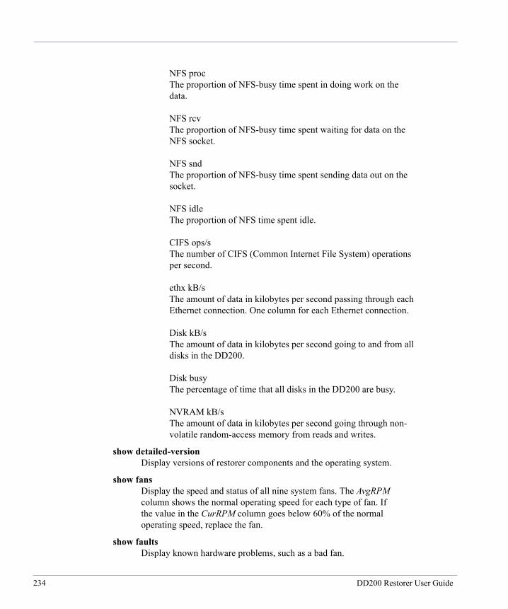
NFS proc The proportion of NFS-busy time spent in doing work on the data. NFS rcv The proportion of NFS-busy time spent waiting for data on the NFS socket. NFS snd The proportion of NFS-busy time spent sending data out on the socket. NFS idle The proportion of NFS time spent idle. CIFS ops/s The number of CIFS (Common Internet File System) operations per second. ethx kB/s The amount of data in kilobytes per second passing through each Ethernet connection. One column for each Ethernet connection. Disk kB/s The amount of data in kilobytes per second going to and from all disks in the DD200. Disk busy The percentage of time that all disks in the DD200 are busy. NVRAM kB/s The amount of data in kilobytes per second going through non- volatile random-access memory from reads and writes.
show detailed-version Display versions of restorer components and the operating system.
show fans Display the speed and status of all nine system fans. The AvgRPM column shows the normal operating speed for each type of fan. If the value in the CurRPM column goes below 60% of the normal operating speed, replace the fan.
show faults Display known hardware problems, such as a bad fan.
234 DD200 Restorer User Guide
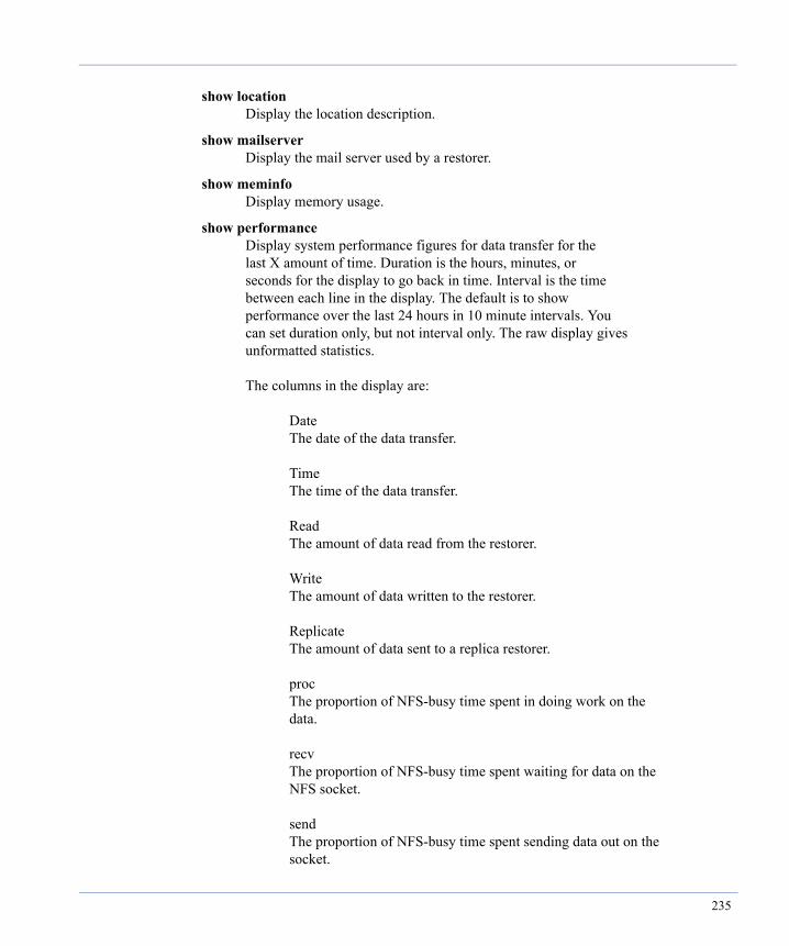
show location Display the location description.
show mailserver Display the mail server used by a restorer.
show meminfo Display memory usage.
show performance Display system performance figures for data transfer for the last X amount of time. Duration is the hours, minutes, or seconds for the display to go back in time. Interval is the time between each line in the display. The default is to show performance over the last 24 hours in 10 minute intervals. You can set duration only, but not interval only. The raw display gives unformatted statistics. The columns in the display are: Date The date of the data transfer. Time The time of the data transfer. Read The amount of data read from the restorer. Write The amount of data written to the restorer. Replicate The amount of data sent to a replica restorer. proc The proportion of NFS-busy time spent in doing work on the data. recv The proportion of NFS-busy time spent waiting for data on the NFS socket. send The proportion of NFS-busy time spent sending data out on the socket.
235

idle The proportion of NFS time spent idle.
show serialno Display the system serial number.
show settings Display the system date and time, time server, time zone, system location, and mail server.
show stats Display system statistics for the use of CPUs, disks, Ethernet ports, and by NFS operations. The time period covered is from the last reboot, except when using interval and count.
An interval, in seconds, runs the command every given number of seconds for the number of times in count. The first report covers the time period since the last reboot. Each subsequent report is for activity in the last interval. The default interval is two seconds.
The start and stop options return averages per second of statistics over the time between the commands.
show timezone Display the time zone set on the restorer.
show uptime Display the amount of time that has passed since the last reboot.
show version Display the version of restorer system software.
status Display hardware status, such as processor vital signs, internal temperatures, and power supply output.
upgrade Upgrade restorer software from the Data Domain web site or a CD. Note that the upgrade operation shuts down the restorer file system and reboots the machine. Administrative users only.
To upgrade from the Data Domain web site:
Log in to a restorer administrative host that mounts /ddvar from the restorer.
Open a browser and go to the Data Domain Support web site.
236 DD200 Restorer User Guide

Download the new release file to the directory /ddvar/releases.
To start the upgrade, log in to a restorer as sysadmin and enter the following command:
system upgrade ddr_1.0_rpm
To upgrade from a CD:
Log in to a restorer as sysadmin.
Insert the CD into the restorer CD drive.
Enter a command similar to the following using the file name from the CD:
system upgrade ddr_1.0_rpm
EXAMPLES To display I/O statistics every 30 seconds for 10 iterations, use the following command:
system show stats 30 10
To set the date and time to October 26 at 3:24 p.m. in the year 2003, use either of the following commands:
system set date 1026152403 system set date 102615242003
To set the time zone for the Pacific coast of the U.S.A.:
system set timezone Los_Angeles
To find all time zones that include a match for "new":
system set timezone new Ambiguous timezone name, matching ... America/New_York Canada/Newfoundland
Restore Protection Manager 1 November 2004
237

system setNAME system set - Sets the date, time, and mail parameters for Restore Protection Manager (restorer).
SYNOPSIS system set admin-email email-addr
system set admin-host host-name
system set {date MMDDhhmm[[CC]YY] | timezone zone-name}
system set location location
system set mailserver host
DESCRIPTION The system set command sets the system date and time, time zone, NDS server from which to synchronize the system clock, and the server through which the restorer should send email.
OPERATIONS set admin-email Set an address for email messages from the alerts and autosupport utilities. The system needs one and only one admin-email address. Use the autosupport and alerts commands to add other email addresses.
set admin-host Set the machine from which you can log into the DD200 to see system logs and use system commands. The host name can be a simple host name, a fully-qualified host name, or an IP address.
set date Set the system clock and date. Administrative users only. The entry components are two places for month (MM of 01 through 12), two places for day of the month (DD 01 through 31), two places for hours (hh or 00 through 23), two places for minutes (mm of 00 through 59), and optionally, two places for century (CC) and two places for year (YY). Time is 24-hour military time. 2400 is not a valid time. A time of "0000" is midnight as the beginning of a day.
set location Give a description of the physical location of the restorer. The location appears in autosupport and alerts emails to help identify the machine.
238 DD200 Restorer User Guide
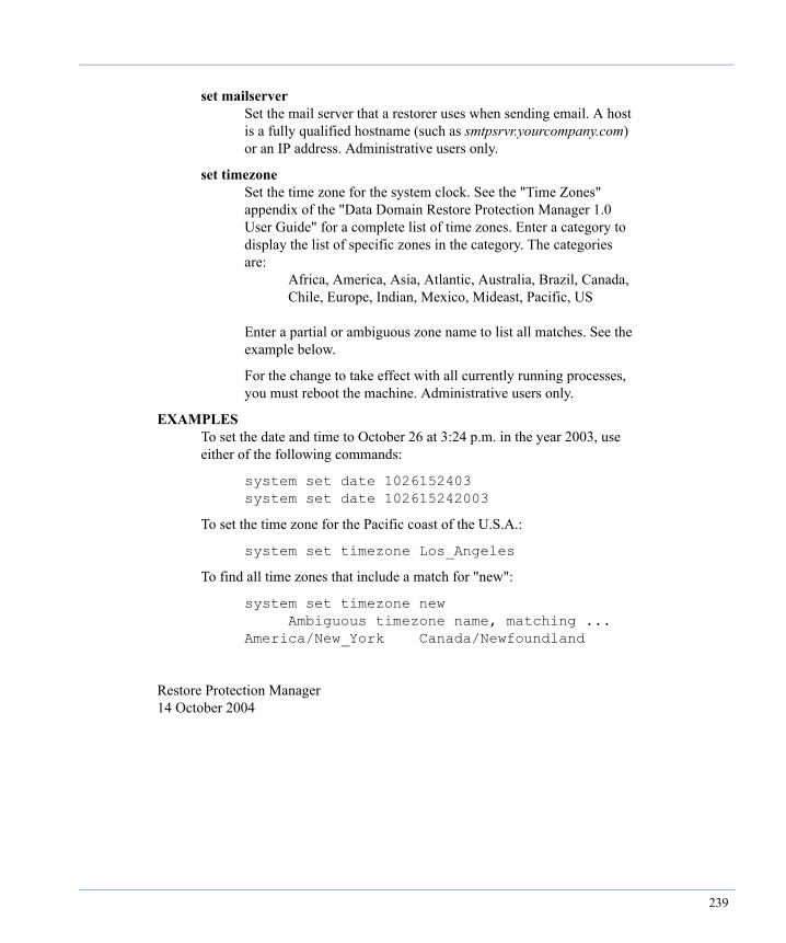
set mailserver Set the mail server that a restorer uses when sending email. A host is a fully qualified hostname (such as smtpsrvr.yourcompany.com) or an IP address. Administrative users only.
set timezone Set the time zone for the system clock. See the "Time Zones" appendix of the "Data Domain Restore Protection Manager 1.0 User Guide" for a complete list of time zones. Enter a category to display the list of specific zones in the category. The categories are: Africa, America, Asia, Atlantic, Australia, Brazil, Canada, Chile, Europe, Indian, Mexico, Mideast, Pacific, US Enter a partial or ambiguous zone name to list all matches. See the example below.
For the change to take effect with all currently running processes, you must reboot the machine. Administrative users only.
EXAMPLES To set the date and time to October 26 at 3:24 p.m. in the year 2003, use either of the following commands:
system set date 1026152403 system set date 102615242003
To set the time zone for the Pacific coast of the U.S.A.:
system set timezone Los_Angeles
To find all time zones that include a match for "new":
system set timezone new Ambiguous timezone name, matching ... America/New_York Canada/Newfoundland
Restore Protection Manager 14 October 2004
239
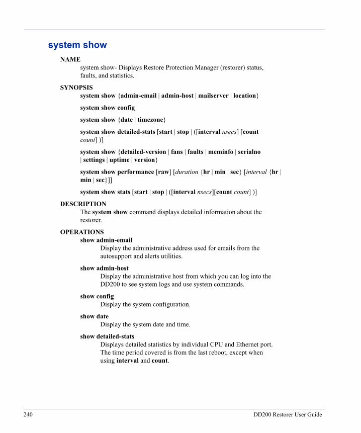
system showNAME system show- Displays Restore Protection Manager (restorer) status, faults, and statistics.
SYNOPSIS system show {admin-email | admin-host | mailserver | location}
system show config
system show {date | timezone}
system show detailed-stats [start | stop | ([interval nsecs] [count count] )]
system show {detailed-version | fans | faults | meminfo | serialno | settings | uptime | version}
system show performance [raw] [duration {hr | min | sec} [interval {hr | min | sec}]]
system show stats [start | stop | ([interval nsecs][count count] )]
DESCRIPTION The system show command displays detailed information about the restorer.
OPERATIONS show admin-email Display the administrative address used for emails from the autosupport and alerts utilities.
show admin-host Display the administrative host from which you can log into the DD200 to see system logs and use system commands.
show config Display the system configuration.
show date Display the system date and time.
show detailed-stats Displays detailed statistics by individual CPU and Ethernet port. The time period covered is from the last reboot, except when using interval and count.
240 DD200 Restorer User Guide
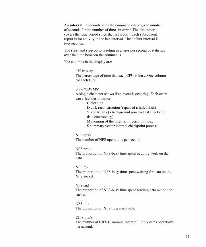
An interval, in seconds, runs the command every given number of seconds for the number of times in count. The first report covers the time period since the last reboot. Each subsequent report is for activity in the last interval. The default interval is two seconds.
The start and stop options return averages per second of statistics over the time between the commands.
The columns in the display are: CPUx busy The percentage of time that each CPU is busy. One column for each CPU. State 'CDVMS' A single character shows if an event is occuring. Each event can affect performance. C cleaning D disk reconstruction (repair of a failed disk) V verify data (a background process that checks for data consistency) M merging of the internal fingerprint index S summary vector internal checkpoint process NFS ops/s The number of NFS operations per second. NFS proc The proportion of NFS-busy time spent in doing work on the data. NFS rcv The proportion of NFS-busy time spent waiting for data on the NFS socket. NFS snd The proportion of NFS-busy time spent sending data out on the socket. NFS idle The proportion of NFS time spent idle. CIFS ops/s The number of CIFS (Common Internet File System) operations per second.
241

ethx kB/s The amount of data in kilobytes per second passing through each Ethernet connection. One column for each Ethernet connection. Disk kB/s The amount of data in kilobytes per second going to and from all disks in the DD200. Disk busy The percentage of time that all disks in the DD200 are busy. NVRAM kB/s The amount of data in kilobytes per second going through non- volatile random-access memory from reads and writes.
show detailed-version Display versions of restorer components and the operating system.
show fans Display the speed and status of all nine system fans. The AvgRPM column shows the normal operating speed for each type of fan. If the value in the CurRPM column goes below 60% of the normal operating speed, replace the fan.
show faults Display known hardware problems, such as a bad fan.
show location Display the location description.
show mailserver Display the mail server used by the restorer.
show meminfo Display memory usage.
show performance Display system performance figures for data transfer for the last X amount of time. Duration is the hours, minutes, or seconds for the display to go back in time. Interval is the time between each line in the display. The default is to show performance over the last 24 hours in 10 minute intervals. You can set duration only, but not interval only. The raw display gives unformatted statistics.
The columns in the display are: Date
242 DD200 Restorer User Guide
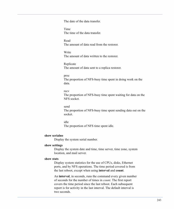
The date of the data transfer. Time The time of the data transfer. Read The amount of data read from the restorer. Write The amount of data written to the restorer. Replicate The amount of data sent to a replica restorer. proc The proportion of NFS-busy time spent in doing work on the data. recv The proportion of NFS-busy time spent waiting for data on the NFS socket. send The proportion of NFS-busy time spent sending data out on the socket. idle The proportion of NFS time spent idle.
show serialno Display the system serial number.
show settings Display the system date and time, time server, time zone, system location, and mail server.
show stats Display system statistics for the use of CPUs, disks, Ethernet ports, and by NFS operations. The time period covered is from the last reboot, except when using interval and count.
An interval, in seconds, runs the command every given number of seconds for the number of times in count. The first report covers the time period since the last reboot. Each subsequent report is for activity in the last interval. The default interval is two seconds.
243
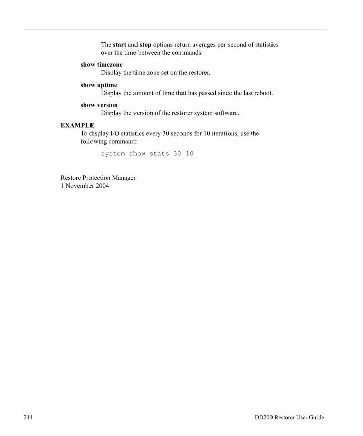
The start and stop options return averages per second of statistics over the time between the commands.
show timezone Display the time zone set on the restorer.
show uptime Display the amount of time that has passed since the last reboot.
show version Display the version of the restorer system software.
EXAMPLE To display I/O statistics every 30 seconds for 10 iterations, use the following command:
system show stats 30 10
Restore Protection Manager 1 November 2004
244 DD200 Restorer User Guide
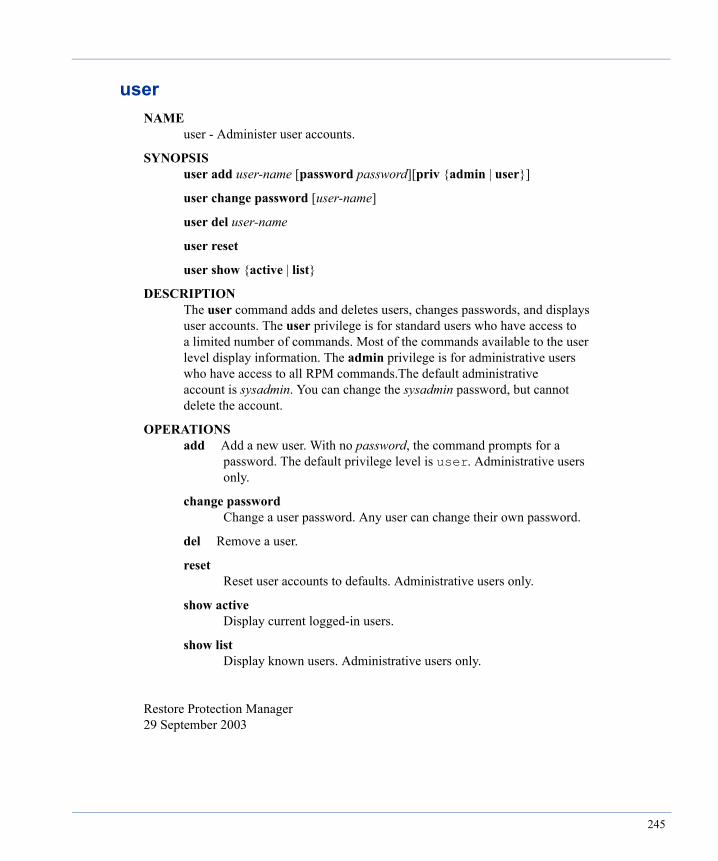
userNAME user - Administer user accounts.
SYNOPSIS user add user-name [password password][priv {admin | user}]
user change password [user-name]
user del user-name
user reset
user show {active | list}
DESCRIPTION The user command adds and deletes users, changes passwords, and displays user accounts. The user privilege is for standard users who have access to a limited number of commands. Most of the commands available to the user level display information. The admin privilege is for administrative users who have access to all RPM commands.The default administrative account is sysadmin. You can change the sysadmin password, but cannot delete the account.
OPERATIONS add Add a new user. With no password, the command prompts for a password. The default privilege level is user. Administrative users only.
change password Change a user password. Any user can change their own password.
del Remove a user.
reset Reset user accounts to defaults. Administrative users only.
show active Display current logged-in users.
show list Display known users. Administrative users only.
Restore Protection Manager 29 September 2003
245

246 DD200 Restorer User Guide

Index
Aadminaccess command 37administrative email
change the address 76display address 85
administrative hostchange 76display host name 85
AIX 29alarm, turn off 142alerts
add an email address 46command 46display current 47display current and history 48display the email list 47display the history 48remove an address from the email list 46set the email list to the default 47test the list 46
aliasadd 87command 87defaults 88display 88remove 87
authentication mode for CIFS 112autonegotiate, set 95autosupport
command 49display all parameters 52display history file 53display list 53display schedule 54remove an email address 49
run the report 51See also system reportset all parameters to default 51set list to the default 50set the schedule 50set the schedule to the default 51test report 50
Bbackup
recommendations for full 3buzzer, turn off 142CCIFS
add a backup client 110add a client 110add a user 109add an administrative client 111configuration set up 24disable client connections 110display active clients 114display clients 114display configuration 115display mappings 116display statistics 115display status 115enable client connections 110identify a WINS server 113map IP address to NetBIOS hostname 112remove a client 111remove all clients 111remove all IP address/hostname mappings 113remove an administrative client 111remove an IP address/hostname mapping 113remove the NetBIOS hostname 112remove the WINS server 114
247
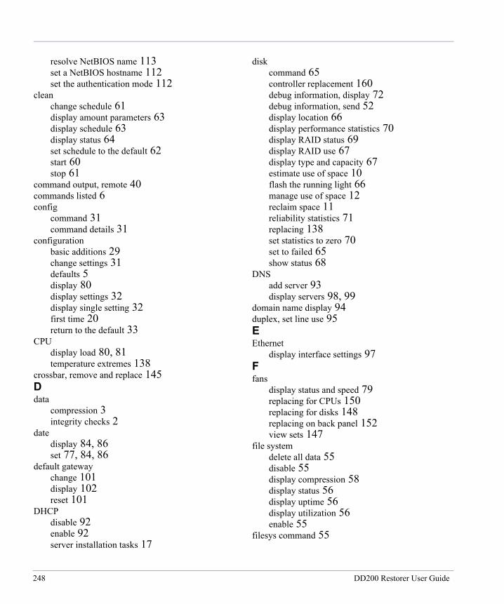
resolve NetBIOS name 113set a NetBIOS hostname 112set the authentication mode 112
cleanchange schedule 61display amount parameters 63display schedule 63display status 64set schedule to the default 62start 60stop 61
command output, remote 40commands listed 6config
command 31command details 31
configurationbasic additions 29change settings 31defaults 5display 80display settings 32display single setting 32first time 20return to the default 33
CPUdisplay load 80, 81temperature extremes 138
crossbar, remove and replace 145Ddata
compression 3integrity checks 2
datedisplay 84, 86set 77, 84, 86
default gatewaychange 101display 102reset 101
DHCPdisable 92enable 92server installation tasks 17
diskcommand 65controller replacement 160debug information, display 72debug information, send 52display location 66display performance statistics 70display RAID status 69display RAID use 67display type and capacity 67estimate use of space 10flash the running light 66manage use of space 12reclaim space 11reliability statistics 71replacing 138set statistics to zero 70set to failed 65show status 68
DNSadd server 93display servers 98, 99
domain name display 94duplex, set line use 95EEthernet
display interface settings 97Ffans
display status and speed 79replacing for CPUs 150replacing for disks 148replacing on back panel 152view sets 147
file systemdelete all data 55disable 55display compression 58display status 56display uptime 56display utilization 56enable 55
filesys command 55
248 DD200 Restorer User Guide
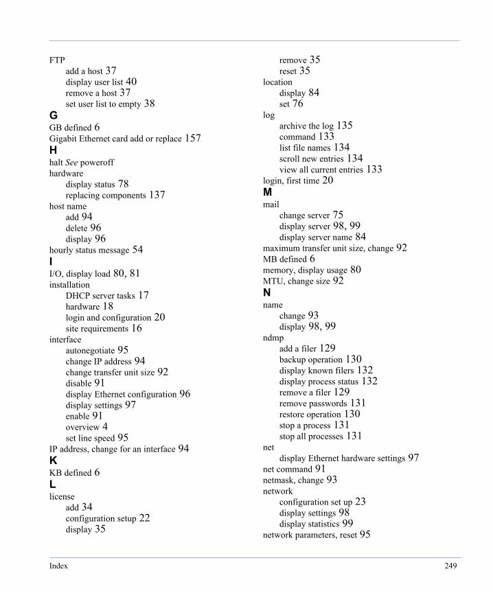
FTPadd a host 37display user list 40remove a host 37set user list to empty 38
GGB defined 6Gigabit Ethernet card add or replace 157Hhalt See poweroffhardware
display status 78replacing components 137
host nameadd 94delete 96display 96
hourly status message 54II/O, display load 80, 81installation
DHCP server tasks 17hardware 18login and configuration 20site requirements 16
interfaceautonegotiate 95change IP address 94change transfer unit size 92disable 91display Ethernet configuration 96display settings 97enable 91overview 4set line speed 95
IP address, change for an interface 94KKB defined 6Llicense
add 34configuration setup 22display 35
remove 35reset 35
locationdisplay 84set 76
logarchive the log 135command 133list file names 134scroll new entries 134view all current entries 133
login, first time 20Mmail
change server 75display server 98, 99display server name 84
maximum transfer unit size, change 92MB defined 6memory, display usage 80MTU, change size 92Nname
change 93display 98, 99
ndmpadd a filer 129backup operation 130display known filers 132display process status 132remove a filer 129remove passwords 131restore operation 130stop a process 131stop all processes 131
netdisplay Ethernet hardware settings 97
net command 91netmask, change 93network
configuration set up 23display settings 98display statistics 99
network parameters, reset 95
Index 249
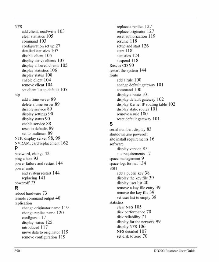
NFSadd client, read/write 103clear statistics 105command 103configuration set up 27detailed statistics 107disable client 105display active clients 107display allowed clients 105display statistics 106display status 108enable client 104remove client 104set client list to default 105
ntpadd a time server 89delete a time server 89disable service 89display settings 90display status 90enable service 88reset to defaults 89set to multicast 89
NTP, display server 98, 99NVRAM, card replacement 162Ppassword, change 42ping a host 93power failure and restart 144power units
and system restart 144replacing 141
poweroff 73Rreboot hardware 73remote command output 40replication
change originator name 119change replica name 120configure 117display status 125introduced 117move data to originator 119remove configuration 119
replace a replica 127replace originator 127reset authorization 119resume 118setup and start 126start 118statistics 124suspend 118
Rescue CD 90restart the system 144route
add a rule 100change default gateway 101command 100display a route 101display default gateway 102display Kernel IP routing table 102display static routes 101remove a rule 100reset default gateway 101
Sserial number, display 83shutdown See poweroffsite install requirements 16software
display version 85site requirements 17
space management 9space.log, format 134SSH
add a public key 38display the key file 39display user list 40remove a key file entry 39remove the key file 39set user list to empty 38
statisticsclear NFS 105disk performance 70disk reliability 71display for the network 99display NFS 106NFS detailed 107set disk to zero 70
250 DD200 Restorer User Guide
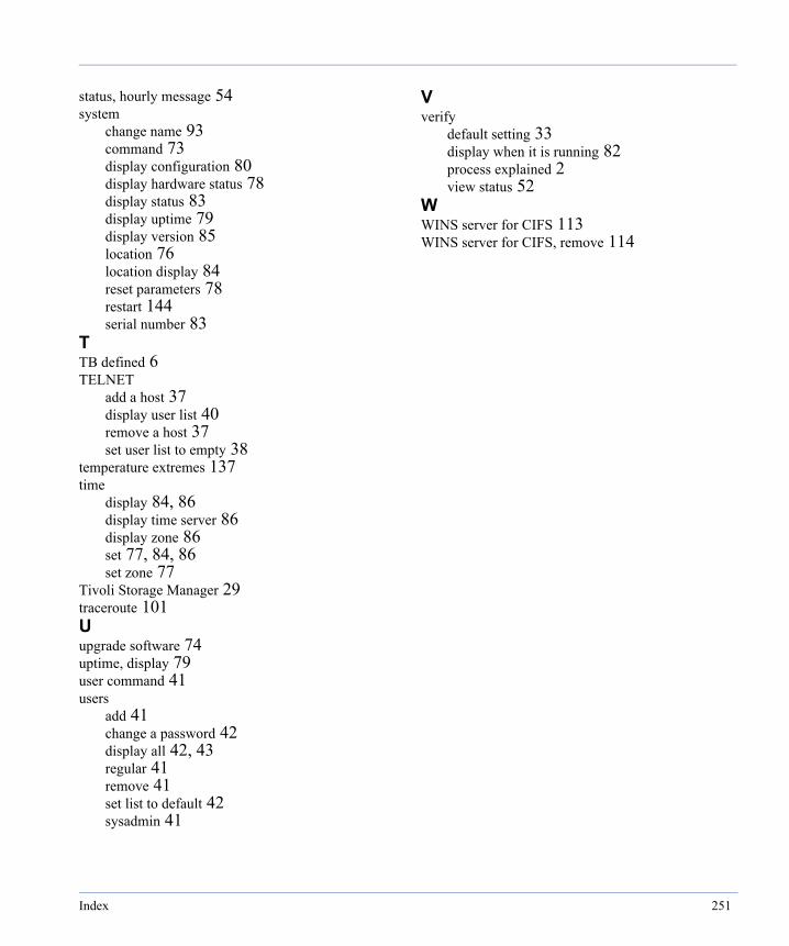
status, hourly message 54system
change name 93command 73display configuration 80display hardware status 78display status 83display uptime 79display version 85location 76location display 84reset parameters 78restart 144serial number 83
TTB defined 6TELNET
add a host 37display user list 40remove a host 37set user list to empty 38
temperature extremes 137time
display 84, 86display time server 86display zone 86set 77, 84, 86set zone 77
Tivoli Storage Manager 29traceroute 101Uupgrade software 74uptime, display 79user command 41users
add 41change a password 42display all 42, 43regular 41remove 41set list to default 42sysadmin 41
Vverify
default setting 33display when it is running 82process explained 2view status 52
WWINS server for CIFS 113WINS server for CIFS, remove 114
Index 251

252 DD200 Restorer User Guide

© 2011 - 2013 EMC Corporation. All Rights Reserved. EMC believes the information in this publication is accurate as of its publication date. The information is subject to change
without
notice.
THE INFORMATION IN THIS PUBLICATION IS PROVIDED “AS IS.” EMC CORPORATION MAKES NO
REPRESENTATIONS OR
WARRANTIES OF ANY KIND WITH RESPECT TO THE INFORMATION IN THIS PUBLICATION, AND
SPECIFICALLY
DISCLAIMS IMPLIED WARRANTIES OF MERCHANTABILITY OR FITNESS FOR A PARTICULAR PURPOSE.
Use, copying, and distribution of any EMC software described in this publication requires an applicable software license.
EMC2, EMC, and the EMC logo are registered trademarks or trademarks of EMC Corporation in the United State and other
countries.
All other trademarks used herein are the property of their respective owners.