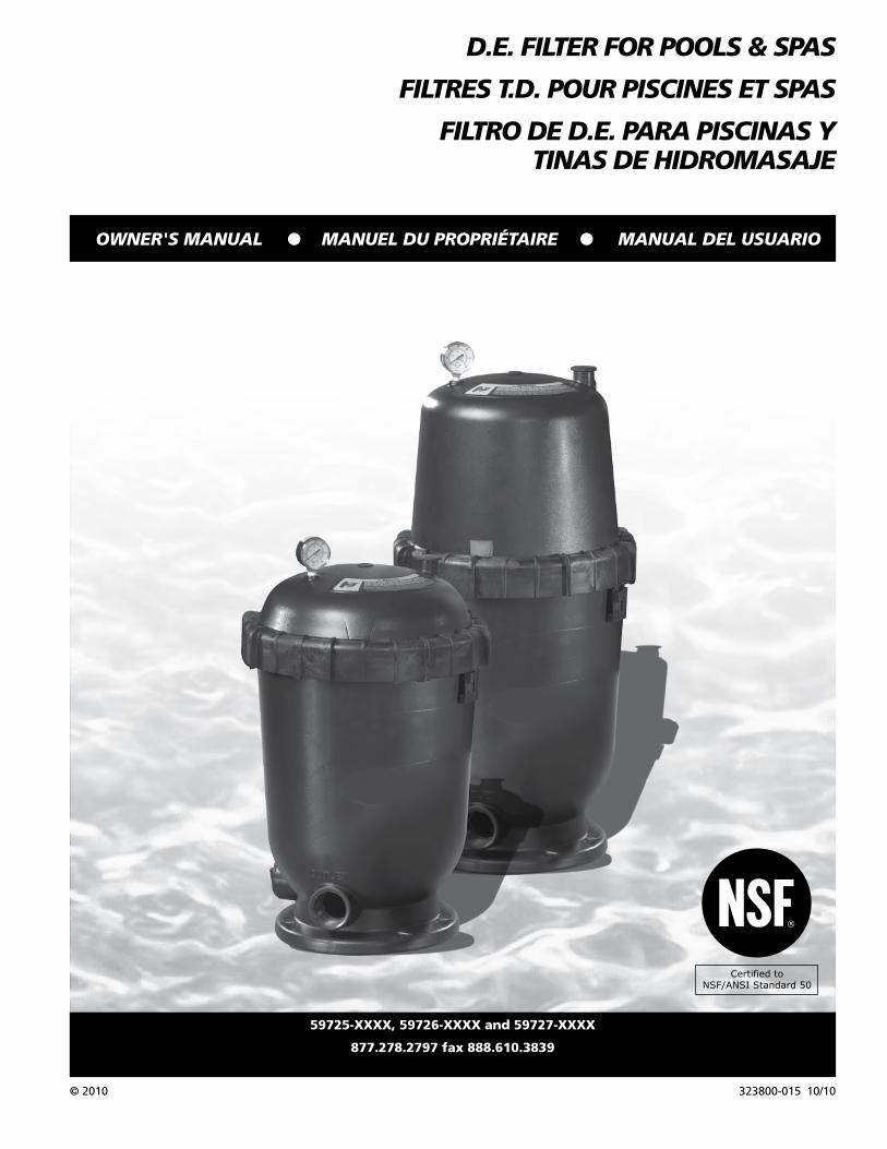
d.e. filter for pools & spas filtres t ... - the … 59725-xxxx, 59726-xxxx and 59727-xxxx...
TRANSCRIPT
323800-015 10/10
OWNER'S MANUAL O� MANUEL DU PROPRIÉTAIRE� O MANUAL DEL USUARIO
© 2010
59725-XXXX, 59726-XXXX and 59727-XXXX
877.278.2797 fax 888.610.3839
D.E. FILTER FOR POOLS & SPAS
FILTRES T.D. POUR PISCINES ET SPAS
FILTRO DE D.E. PARA PISCINAS Y TINAS DE HIDROMASAJE
Certified toNSF/ANSI Standard 50
®

2
Operating Instructions and Parts List
Table of ContentsDescription . . . . . . . . . . . . . . . . . . . . . .2Unpacking . . . . . . . . . . . . . . . . . . . . . . .2General Safety Information . . . . . . 2 - 3Pool / Spa Chemistry . . . . . . . . . . . . . . .3Specifications. . . . . . . . . . . . . . . . . . 4 - 5Installation Procedures . . . . . . . . . . . . .6 Equipment Inspection . . . . . . . . . . .6 Equipment Location . . . . . . . . . . . . .6 Plumbing. . . . . . . . . . . . . . . . . . . . . .6 Electrical . . . . . . . . . . . . . . . . . . . . . .6 Assembly . . . . . . . . . . . . . . . . . . . . . .6 New Pool / Spa Installations . . . . . . .6Initial Start-Up. . . . . . . . . . . . . . . . . . . .7Filter Disassembly . . . . . . . . . . . . . . . . .8Cartridge Cleaning . . . . . . . . . . . . . . . .8Filter Assembly . . . . . . . . . . . . . . . . . . .9System Inspection . . . . . . . . . . . . . . . . .9Winterizing . . . . . . . . . . . . . . . . . . . . . .9Troubleshooting Guide. . . . . . . . . . . .10Replacement Parts . . . . . . . . . . . . . . .11Warranty . . . . . . . . . . . . . . . . . . . . . . .12
DescriptionThis pool filter is designed to use diatomaceous earth (D.E.) to remove debris and particulates from permanently installed swimming pools and spas. D.E. is a form of sedimentary rock that contains fossilized remains of one-celled algae called diatoms. When ground into a powder and applied to a filter element, D.E. makes an excellent filter media by trapping debris in the microscopic holes in the fossils. After it becomes clogged with debris, the spent D.E. can easily be washed away so a new, fresh coat can be applied. This filter is equipped with a cartridge-style filter element that can be easily removed for cleaning or replacement.
UnpackingInspect this unit before it is used. Occasionally, products are damaged during shipment. If the filter or components are damaged, return the unit to the place of purchase for replacement. Failure to do so could result in serious injury or death.
READ & FOLLOW ALL INSTRUCTIONS SAVE THESE INSTRUCTIONS
DO NOT DISCARD
Safety GuidelinesThis manual contains information that is very important to know and understand. This information is provided for SAFETY and to PREVENT EQUIPMENT PROBLEMS. To help recognize this information, observe the following symbols. Danger indicates an
imminently hazardous situation which, if not avoided, WILL result in death or serious injury. Warning indicates a
potentially hazardous situation which, if not avoided, COULD result in death or serious injury. Caution indicates a
potentially hazardous situation which, if not avoided, MAY result in minor or moderate injury. Notice indicates
important information, that if not followed, may cause damage to equipment.
NOTE: Information that requires special attention.
General Safety InformationCALIFORNIA PROPOSITION 65 This product
may contain chemicals known to the State of California to cause cancer and birth defects or other reproductive harm. Wash hands after handling.
GENERAL SAFETY
Read all manuals included with this product carefully. Be thoroughly familiar with the controls and the proper use of the equipment.
This filter operates
under high pressure. Incorrectly installed or serviced equipment could explode, causing severe injury, death, and/or property damage.
perform all pressure tests.
compressed air under any circumstances.
installation.
or any other external source of pressurized water.
capable of exceeding 50 psi (345 kPa) pressure.
excess of 50 psi (345 kPa), even when conducting hydrostatic pressure tests. Pressures exceeding 50 psi can cause the tank to rupture and could result in severe injury, death or property damage.
an explosion. Open the air relief valve to vent all air from the system before operating or testing the system.
Do not use solvents to clean the filter
assembly as they may damage the plastic components.
Wear rubber
gloves, protective clothing and eyewear when using acids and cleaners. Avoid contact with skin and eyes. If ingested, call local poison control center. Observe all warnings and precautions supplied with acids and cleaners.
Please read and save these instructions. Read carefully before attempting to assemble, install, operate or maintain the product described. Protect yourself and others by observing all safety information. Failure to comply with instructions could result in personal injury and/or property damage! Retain instructions for future reference.
REMINDER: Keep your dated proof of purchase for warranty purposes! Attach it to this manual or file it for safekeeping.
MANUAL
© 2010
323800-015
3
59725-XXXX, 59726-XXXX and 59727-XXXX
General Safety Information (Continued) Risk of
electrical shock or electrocution.
and air relief valve to safely direct drainage and purged air or water away from the pump and other electrical components. Water discharged from an improperly positioned assembly can create an electrical hazard that can cause serious injury, death, and/or property damage.
meets local codes and National Electrical Code (NEC) standards. All wiring, grounding, and bonding of associated equipment must be performed by a qualified electrician. Installations must be in accordance with local and national codes.
Risk of falling and drowning.
meters) from pool (or spa) so that children cannot climb over it into pool.
equipment.
unattended. Secure area where filter is installed.
equipment, especially when servicing.
This filter is designed to remove
debris and particulates from pool and spa water. Proper water chemistry MUST be maintained to keep water clean and avoid spreading diseases. Consult a local pool professional for more information.
This filter is not designed for
backwashing. If unit is plumbed backwards or backwashed, it will damage the filter cartridge and will void the warranty.
Attention Installer: This manual contains important information about the installation, operation and safe use of this filter. This information should be furnished to the end user of this equipment.
Attention User: SAVE THESE INSTRUCTIONS.
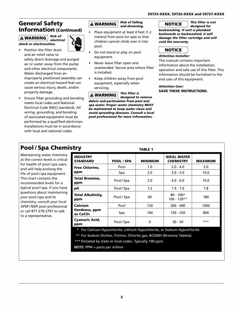
Pool / Spa ChemistryMaintaining water chemistry at the correct levels is critical for health of pool / spa users and will help prolong the life of pool / spa equipment. This chart contains the recommended levels for a typical pool / spa. If you have questions about maintaining your pool / spa and its chemistry, consult your local APSP / NSPI pool professional or call 877-278-2797 to talk to a representative.
INDUSTRY STANDARD POOL / SPA MINIMUM
IDEAL WATER CHEMISTRY MAXIMUM
Free Chlorine, ppm
Pool 1.0 2.0 - 4.0 5.0
Spa 2.0 3.0 - 5.0 10.0
Total Bromine, ppm Pool / Spa 2.0 4.0 - 6.0 10.0
pH Pool / Spa 7.2 7.4 - 7.6 7.8
Total Alkalinity, ppm Pool / Spa 60 80 - 100*
100 - 120** 180
Calcium Hardness, ppm as CaCO3
Pool 150 200 - 400 1000
Spa 100 150 - 250 800
Cyanuric Acid, ppm Pool / Spa 0 30 - 50 ***
* For Calcium Hypochlorite, Lithium Hypochlorite, or Sodium Hypochlorite
** For Sodium Dichlor, Trichlor, Chlorite gas, BCDMH (Bromine Tablets).
*** Dictated by state or local codes. Typically 100 ppm.
NOTE: PPM = parts per million
TABLE 1
4
Operating Instructions and Parts List
www.aquaprosystems.com
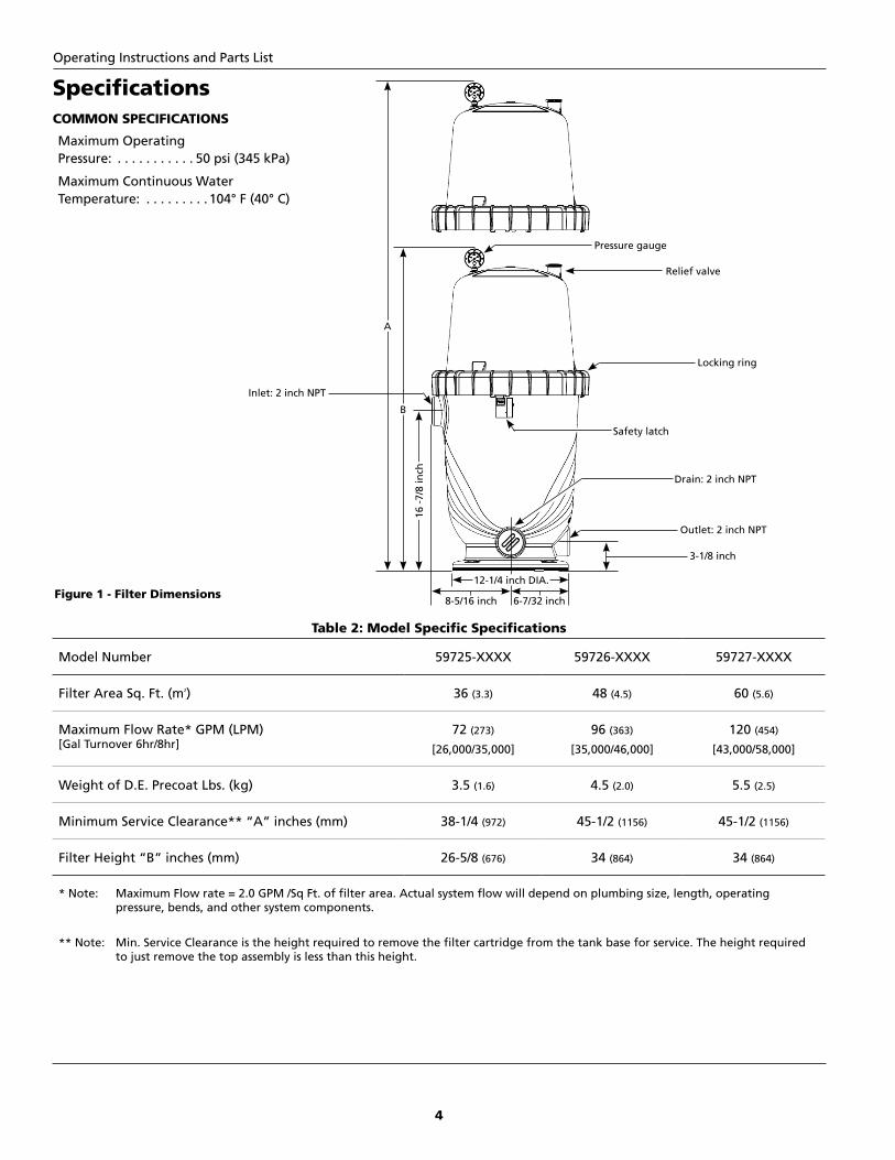
Table 2: Model Specific Specifications
Model Number 59725-XXXX 59726-XXXX 59727-XXXX
Filter Area Sq. Ft. (m2) 36 (3.3) 48 (4.5) 60 (5.6)
Maximum Flow Rate* GPM (LPM) [Gal Turnover 6hr/8hr]
72 (273)
[26,000/35,000]
96 (363)
[35,000/46,000]
120 (454)
[43,000/58,000]
Weight of D.E. Precoat Lbs. (kg) 3.5 (1.6) 4.5 (2.0) 5.5 (2.5)
Minimum Service Clearance** “A” inches (mm) 38-1/4 (972) 45-1/2 (1156) 45-1/2 (1156)
Filter Height “B” inches (mm) 26-5/8 (676) 34 (864) 34 (864)
* Note: Maximum Flow rate = 2.0 GPM /Sq Ft. of filter area. Actual system flow will depend on plumbing size, length, operating pressure, bends, and other system components.
** Note: Min. Service Clearance is the height required to remove the filter cartridge from the tank base for service. The height required to just remove the top assembly is less than this height.
SpecificationsCOMMON SPECIFICATIONS
Maximum Operating Pressure: . . . . . . . . . . . 50 psi (345 kPa)
Maximum Continuous Water Temperature: . . . . . . . . . 104° F (40° C)
Relief valve
Pressure gauge
Locking ring
Safety latch
Outlet: 2 inch NPT
Inlet: 2 inch NPT
Drain: 2 inch NPT
3-1/8 inch
12-1/4 inch DIA.
6-7/32 inch8-5/16 inch
A
B16
-7/8
inch
Figure 1 - Filter Dimensions

5
www.aquaprosystems.com
Specifications (Continued)
Figure 2 - Piping Connections
Union Coupling
Filter
Pump
Union Coupling
To Pool
From Pool
Outlet
InletUnion Coupling
Figure 3 - Filter Pressure Loss Curve
59725-XXXX, 59726-XXXX and 59727-XXXX
6
Operating Instructions and Parts List
www.aquaprosystems.com
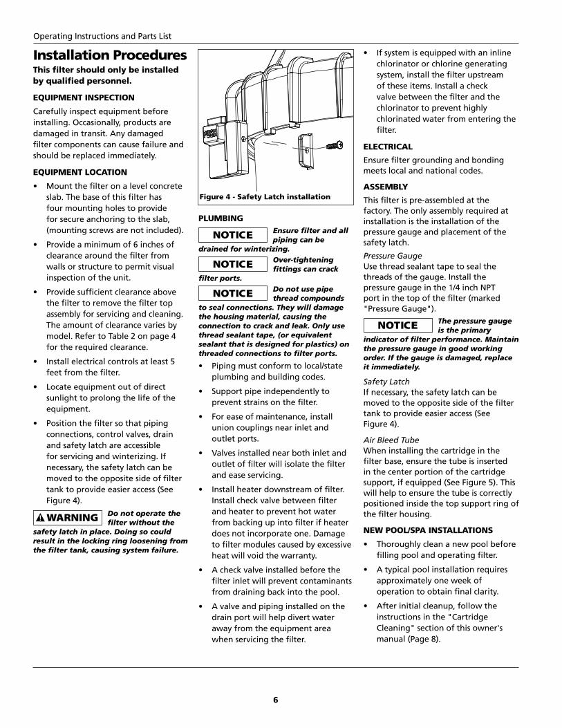
Installation ProceduresThis filter should only be installed by qualified personnel.
EQUIPMENT INSPECTION
Carefully inspect equipment before installing. Occasionally, products are damaged in transit. Any damaged filter components can cause failure and should be replaced immediately.
EQUIPMENT LOCATION
slab. The base of this filter has four mounting holes to provide for secure anchoring to the slab, (mounting screws are not included).
clearance around the filter from walls or structure to permit visual inspection of the unit.
the filter to remove the filter top assembly for servicing and cleaning. The amount of clearance varies by model. Refer to Table 2 on page 4 for the required clearance.
feet from the filter.
sunlight to prolong the life of the equipment.
connections, control valves, drain and safety latch are accessible for servicing and winterizing. If necessary, the safety latch can be moved to the opposite side of filter tank to provide easier access (See Figure 4).
Do not operate the filter without the
safety latch in place. Doing so could result in the locking ring loosening from the filter tank, causing system failure.
PLUMBING Ensure filter and all
piping can be drained for winterizing. Over-tightening
fittings can crack filter ports. Do not use pipe
thread compounds to seal connections. They will damage the housing material, causing the connection to crack and leak. Only use thread sealant tape, (or equivalent sealant that is designed for plastics) on threaded connections to filter ports.
plumbing and building codes.
prevent strains on the filter.
union couplings near inlet and outlet ports.
outlet of filter will isolate the filter and ease servicing.
Install check valve between filter and heater to prevent hot water from backing up into filter if heater does not incorporate one. Damage to filter modules caused by excessive heat will void the warranty.
filter inlet will prevent contaminants from draining back into the pool.
drain port will help divert water away from the equipment area when servicing the filter.
chlorinator or chlorine generating system, install the filter upstream of these items. Install a check valve between the filter and the chlorinator to prevent highly chlorinated water from entering the filter.
ELECTRICAL
Ensure filter grounding and bonding meets local and national codes.
ASSEMBLY
This filter is pre-assembled at the factory. The only assembly required at installation is the installation of the pressure gauge and placement of the safety latch.
Pressure GaugeUse thread sealant tape to seal the threads of the gauge. Install the pressure gauge in the 1/4 inch NPT port in the top of the filter (marked "Pressure Gauge"). The pressure gauge
is the primary indicator of filter performance. Maintain the pressure gauge in good working order. If the gauge is damaged, replace it immediately.
Safety LatchIf necessary, the safety latch can be moved to the opposite side of the filter tank to provide easier access (See Figure 4).
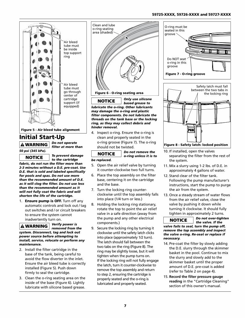
Air Bleed TubeWhen installing the cartridge in the filter base, ensure the tube is inserted in the center portion of the cartridge support, if equipped (See Figure 5). This will help to ensure the tube is correctly positioned inside the top support ring of the filter housing.
NEW POOL/SPA INSTALLATIONS
filling pool and operating filter.
approximately one week of operation to obtain final clarity.
instructions in the "Cartridge Cleaning" section of this owner's manual (Page 8).
Figure 4 - Safety Latch installation
7
www.aquaprosystems.com
Initial Start-Up Do not operate
filter at more than 50 psi (345 kPa). To prevent damage
to the cartridge fabric, do not run the filter more than 2-3 minutes without a D.E. pre-coat. Use D.E. that is sold and labeled specifically for pools and spas. Do not use more than the recommended amount of D.E. as it will clog the filter. Do not use less than the recommended amount as it will not fully coat the fabric and will shorten the life of the cartridge.
1. Ensure pump is OFF. Turn off any automatic controls and lock out / tag out switches and / or circuit breakers to ensure the system cannot inadvertently turn on.
Verify power is removed from the
system. Disconnect, tag and lock out power source before attempting to install, service, relocate or perform any maintenance.
2. Install the filter cartridge in the base of the tank, being careful to avoid the flow diverter in the inlet. Ensure the air bleed tube is correctly installed (Figure 5). Push down firmly to seal the cartridge.
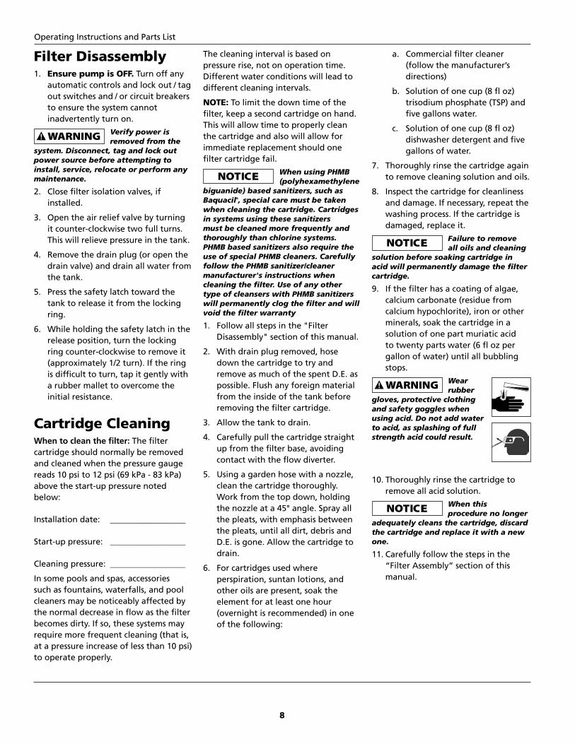
3. Clean the o-ring seating area on the inside of the base (Figure 6). Lightly lubricate with silicone based grease.
Only use silicone based grease to
lubricate the o-ring. Other lubricants may damage the o-ring and plastic filter components. Do not lubricate the threads on the tank base or the locking ring, as they may collect debris and hinder removal.
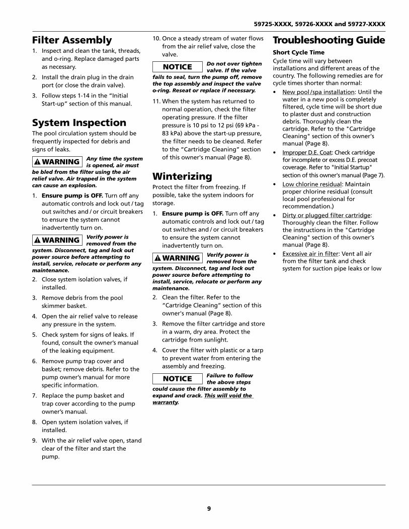
4. Inspect o-ring. Ensure the o-ring is clean and properly seated in the o-ring groove (Figure 7). The o-ring should not be twisted.
Do not remove the o-ring unless it is to
be replaced.
5. Open the air relief valve by turning it counter-clockwise two full turns.
6. Place the top assembly on the filter base, centering it on the cartridge and the base.
7. Turn the locking ring counter-clockwise until the top assembly falls into place (1/4 turn or less.)
8. Holding the locking ring stationary, rotate the top to point the air relief valve in a safe direction (away from the pump and any other electrical components.)
9. Secure the locking ring by turning it clockwise until the safety latch clicks into place (approximately 1/2 turn). The latch should fall between the two tabs on the ring (Figure 8). The ring may be slightly loose, but it will tighten when the pump turns on. If the locking ring will not fully engage the latch, turn it counter-clockwise to remove the top assembly and return to step 2, ensuring the cartridge is properly seated and the o-ring is lubricated and properly seated.
10. If installed, open the valves separating the filter from the rest of the system.
11. Mix a slurry using 1-2 lbs. of D.E. in approximately 4 gallons of water.
12. Stand clear of the filter tank. Following the pump manufacturer's instructions, start the pump to purge the air from the system.
13. Once a steady stream of water flows from the air relief valve, close the valve by pushing it down while turning it clockwise. It should fully tighten in approximately 2 turns.
Do not over-tighten the valve. If the
valve fails to seal, turn the pump off, remove the top assembly and inspect the valve o-ring. Re-seat or replace if necessary.
14. Pre-coat the filter by slowly adding the D.E. slurry through the skimmer basket in the pool. Continue to mix the slurry and slowly add to the skimmer basket until the proper amount of D.E. pre-coat is added (refer to Table 2 on page 4).
15. Record the filter pressure gauge reading in the "Cartridge Cleaning" section of this owner's manual.
Figure 6 - O-ring seating area
Clean and lube o-ring seating area (shaded)
Figure 7 - O-ring groove
O-ring must be seated in this groove
Do NOT seat o-ring in this groove
Figure 8 - Safety latch: locked position
Safety latch must fall between the two tabs in
the locking ring
Figure 5 - Air bleed tube alignment
Air bleed tube must go through center of cartridge support (if equipped)
Air bleed tube must be inside top support ring
59725-XXXX, 59726-XXXX and 59727-XXXX
8
Operating Instructions and Parts List
www.aquaprosystems.com
Filter Disassembly1. Ensure pump is OFF. Turn off any
automatic controls and lock out / tag out switches and / or circuit breakers to ensure the system cannot inadvertently turn on.
Verify power is removed from the
system. Disconnect, tag and lock out power source before attempting to install, service, relocate or perform any maintenance.
2. Close filter isolation valves, if installed.
3. Open the air relief valve by turning it counter-clockwise two full turns. This will relieve pressure in the tank.
4. Remove the drain plug (or open the drain valve) and drain all water from the tank.
5. Press the safety latch toward the tank to release it from the locking ring.
6. While holding the safety latch in the release position, turn the locking ring counter-clockwise to remove it (approximately 1/2 turn). If the ring is difficult to turn, tap it gently with a rubber mallet to overcome the initial resistance.
Cartridge CleaningWhen to clean the filter: The filter cartridge should normally be removed and cleaned when the pressure gauge reads 10 psi to 12 psi (69 kPa - 83 kPa) above the start-up pressure noted below:
Installation date: __________________
Start-up pressure: __________________
Cleaning pressure: __________________
In some pools and spas, accessories such as fountains, waterfalls, and pool cleaners may be noticeably affected by the normal decrease in flow as the filter becomes dirty. If so, these systems may require more frequent cleaning (that is, at a pressure increase of less than 10 psi) to operate properly.
The cleaning interval is based on pressure rise, not on operation time. Different water conditions will lead to different cleaning intervals.
NOTE: To limit the down time of the filter, keep a second cartridge on hand. This will allow time to properly clean the cartridge and also will allow for immediate replacement should one filter cartridge fail. When using PHMB
(polyhexamethylene biguanide) based sanitizers, such as Baquacil®, special care must be taken when cleaning the cartridge. Cartridges in systems using these sanitizers must be cleaned more frequently and thoroughly than chlorine systems. PHMB based sanitizers also require the use of special PHMB cleaners. Carefully follow the PHMB sanitizer/cleaner manufacturer's instructions when cleaning the filter. Use of any other type of cleansers with PHMB sanitizers will permanently clog the filter and will void the filter warranty
1. Follow all steps in the "Filter Disassembly" section of this manual.
2. With drain plug removed, hose down the cartridge to try and remove as much of the spent D.E. as possible. Flush any foreign material from the inside of the tank before removing the filter cartridge.
3. Allow the tank to drain.
4. Carefully pull the cartridge straight up from the filter base, avoiding contact with the flow diverter.
5. Using a garden hose with a nozzle, clean the cartridge thoroughly. Work from the top down, holding the nozzle at a 45° angle. Spray all the pleats, with emphasis between the pleats, until all dirt, debris and D.E. is gone. Allow the cartridge to drain.
6. For cartridges used where perspiration, suntan lotions, and other oils are present, soak the element for at least one hour (overnight is recommended) in one of the following:
a. Commercial filter cleaner (follow the manufacturer’s directions)
b. Solution of one cup (8 fl oz) trisodium phosphate (TSP) and five gallons water.
c. Solution of one cup (8 fl oz) dishwasher detergent and five gallons of water.
7. Thoroughly rinse the cartridge again to remove cleaning solution and oils.
8. Inspect the cartridge for cleanliness and damage. If necessary, repeat the washing process. If the cartridge is damaged, replace it.
Failure to remove all oils and cleaning
solution before soaking cartridge in acid will permanently damage the filter cartridge.
9. If the filter has a coating of algae, calcium carbonate (residue from calcium hypochlorite), iron or other minerals, soak the cartridge in a solution of one part muriatic acid to twenty parts water (6 fl oz per gallon of water) until all bubbling stops.
Wear rubber
gloves, protective clothing and safety goggles when using acid. Do not add water to acid, as splashing of full strength acid could result.
10. Thoroughly rinse the cartridge to remove all acid solution.
When this procedure no longer
adequately cleans the cartridge, discard the cartridge and replace it with a new one.
11. Carefully follow the steps in the “Filter Assembly” section of this manual.
9
www.aquaprosystems.com
Filter Assembly1. Inspect and clean the tank, threads,
and o-ring. Replace damaged parts as necessary.
2. Install the drain plug in the drain port (or close the drain valve).
3. Follow steps 1-14 in the “Initial Start-up” section of this manual.
System InspectionThe pool circulation system should be frequently inspected for debris and signs of leaks. Any time the system
is opened, air must be bled from the filter using the air relief valve. Air trapped in the system can cause an explosion.
1. Ensure pump is OFF. Turn off any automatic controls and lock out / tag out switches and / or circuit breakers to ensure the system cannot inadvertently turn on.
Verify power is removed from the
system. Disconnect, tag and lock out power source before attempting to install, service, relocate or perform any maintenance.
2. Close system isolation valves, if installed.
3. Remove debris from the pool skimmer basket.
4. Open the air relief valve to release any pressure in the system.
5. Check system for signs of leaks. If found, consult the owner’s manual of the leaking equipment.
6. Remove pump trap cover and basket; remove debris. Refer to the pump owner’s manual for more specific information.
7. Replace the pump basket and trap cover according to the pump owner’s manual.
8. Open system isolation valves, if installed.
9. With the air relief valve open, stand clear of the filter and start the pump.
10. Once a steady stream of water flows from the air relief valve, close the valve.
Do not over tighten valve. If the valve
fails to seal, turn the pump off, remove the top assembly and inspect the valve o-ring. Reseat or replace if necessary.
11. When the system has returned to normal operation, check the filter operating pressure. If the filter pressure is 10 psi to 12 psi (69 kPa - 83 kPa) above the start-up pressure, the filter needs to be cleaned. Refer to the “Cartridge Cleaning” section of this owner's manual (Page 8).
WinterizingProtect the filter from freezing. If possible, take the system indoors for storage.
1. Ensure pump is OFF. Turn off any automatic controls and lock out / tag out switches and / or circuit breakers to ensure the system cannot inadvertently turn on.
Verify power is removed from the
system. Disconnect, tag and lock out power source before attempting to install, service, relocate or perform any maintenance.
2. Clean the filter. Refer to the “Cartridge Cleaning” section of this owner's manual (Page 8).
3. Remove the filter cartridge and store in a warm, dry area. Protect the cartridge from sunlight.
4. Cover the filter with plastic or a tarp to prevent water from entering the assembly and freezing.
Failure to follow the above steps
could cause the filter assembly to expand and crack. This will void the warranty.
Troubleshooting GuideShort Cycle TimeCycle time will vary between installations and different areas of the country. The following remedies are for cycle times shorter than normal:
New pool / spa installation: Until the water in a new pool is completely filtered, cycle time will be short due to plaster dust and construction debris. Thoroughly clean the cartridge. Refer to the "Cartridge Cleaning" section of this owner's manual (Page 8).Improper D.E. Coat: Check cartridge for incomplete or excess D.E. precoat coverage. Refer to "Initial Startup" section of this owner's manual (Page 7).Low chlorine residual: Maintain proper chlorine residual (consult local pool professional for recommendation.)Dirty or plugged filter cartridge: Thoroughly clean the filter. Follow the instructions in the "Cartridge Cleaning" section of this owner's manual (Page 8).Excessive air in filter: Vent all air from the filter tank and check system for suction pipe leaks or low
59725-XXXX, 59726-XXXX and 59727-XXXX

10
Operating Instructions and Parts List
www.aquaprosystems.com
water level. Also, check and clean air bleed tube (See Figure 5).Chemical imbalance in water: Check pool chemistry (refer to Table 1 on page 3). Consult local pool professional.Algae in system: Apply heavy dose of chlorine or algicide as recommended by the pool manufacturer and/or local professional.Cartridge is at the end of its life: When cleaning procedure no longer adequately cleans the cartridge, replace the cartridge.Filter is undersized / pump is oversized: Use a filter with higher square footage or use a smaller HP pump. Consult a customer service representative for sizing information at 1-877-278-2797.
Low Flow / High PressureResistance in or after the filter will reduce the flow and increase the pressure inside the filter. Check the following to remedy this problem:
Dirty or plugged filter cartridge: Thoroughly clean the filter. Follow the instructions in the "Cartridge Cleaning" section of this owner's manual (Page 8).Piping is blocked downstream from the filter: Remove the obstruction.Return valve is not fully open: Fully open return valvePiping is too small: Use larger pipe. Consult pool manufacturer.Filter is undersized / pump is oversized: Use a filter with higher square footage or use a smaller HP pump. Consult a customer service representative for sizing information at 1-877-278-2797.
Low Flow / Low PressureResistance before the filter will reduce the flow and pressure inside the filter. Check the following to remedy this problem:
Skimmer basket(s) clogged: Thoroughly clean the skimmer basket(s).Pump plugged: Thoroughly clean the suction trap in the pump.
Drain and skimmer valves are not fully open: Fully open the drain and skimmer valvesPiping is blocked upstream from the filter: Remove the obstruction.
Plugged CartridgeOver time, the filter media will become clogged and will not perform properly. If the cartridge cannot be cleaned, replace it. If the cartridge needs replacement often, check the following:
Improper D.E. precoat: Check cartridge for incomplete or excess D.E. precoat coverage. Refer to "Initial Start-Up" section of this owner's manual (Page 7).Insufficient cleaning: Closely follow the instructions in the "Cartridge Cleaning" section of this owner's manual (Page 8).Excessive air in filter: Vent all air from the filter tank and check system for suction pipe leaks. Also, check and clean air bleed tube (See Figure 5).Low chlorine residual: Maintain proper residual (consult local pool professional.)Chemical imbalance in water: Check pool chemistry (refer to Table 1 on page 3). Consult local pool professional.Algae in system: Apply heavy dose of chlorine or algicide as recommended by the pool manufacturer and/or local professional.High iron content in water: Consult local pool professional.Improper use of powdered chlorine tablets containing binders: Consult local pool professional.Cleaning with incorrect chemicals when using PHMB sanitizers: Replace the filter cartridge. Only use cleaners specifically made for PHMB sanitizers.
Water Not ClearA number of factors can affect water clarity. The following causes should be checked:
Improper D.E. precoat: Check cartridge for incomplete or excess D.E. precoat coverage. Refer to "Initial Start-Up" section of this owner's manual (Page 7).
Chemical imbalance in water: Check pool chemistry (refer to Table 1 on page 3). Consult local pool professional.Low chlorine residual: Maintain proper chlorine residual (consult local pool professional for recommendation).Damaged filter cartridge: If cartridge is torn or punctured, replace it.High iron content in water: Consult local pool professional.Improper use of powdered chlorine tablets containing binders: Consult local pool professional.Algae in system: Apply heavy dose of chlorine or algicide as recommended by the pool manufacturer and/or local professional.
Automatic Pool Cleaner Stops WorkingPool cleaners may be noticeably affected by the normal decrease in flow as the filter becomes clogged. If the filter stops working, thoroughly clean the cartridge. Refer to the "Cartridge Cleaning" section of this owner's manual (Page 8). If the pool cleaner performs better after the filter is cleaned, clean the filter more often than recommended [Note: pressure increase from start-up may be less than 10 psi to 12 psi (69 kPa - 83 kPa)].
11
www.aquaprosystems.com
Part Number by Model
Item Description 59725-XXXX 59726-XXXX 59727-XXXX
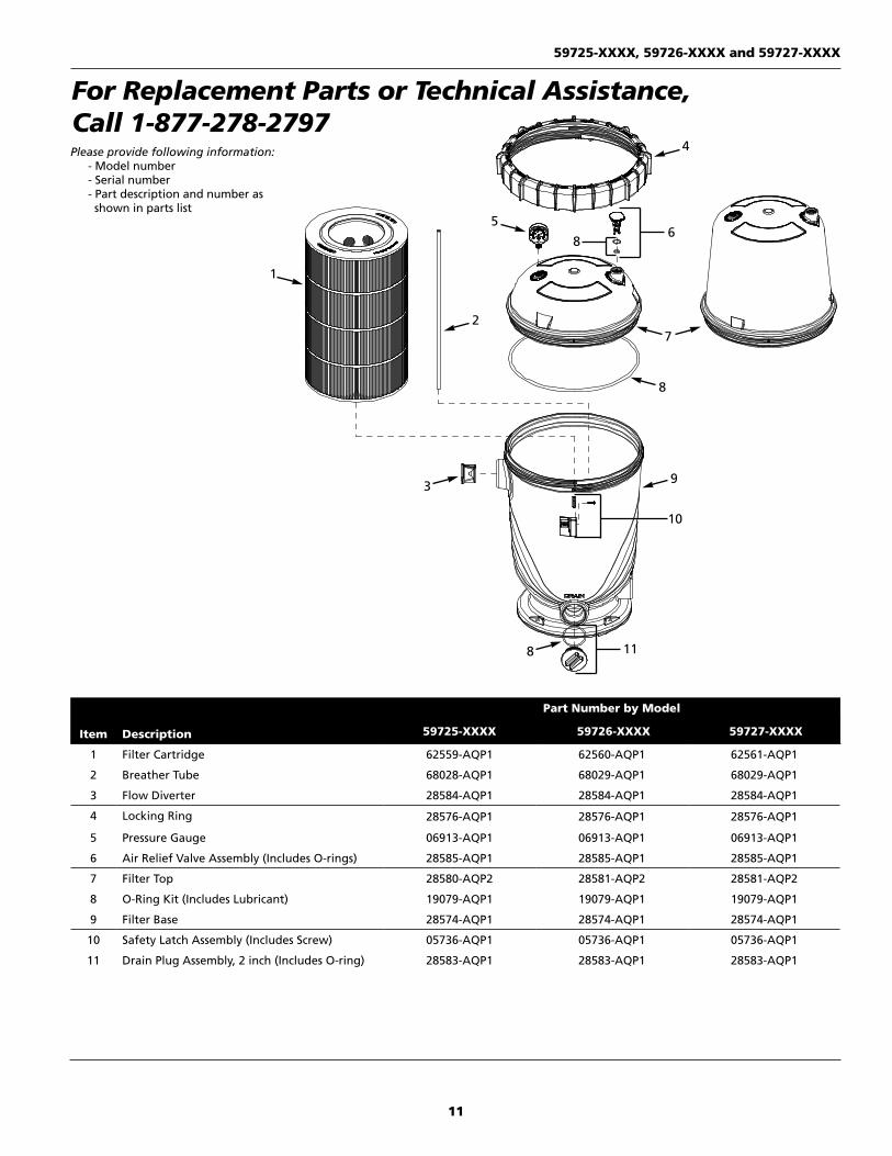
1 Filter Cartridge 62559-AQP1 62560-AQP1 62561-AQP1
2 Breather Tube 68028-AQP1 68029-AQP1 68029-AQP1
3 Flow Diverter 28584-AQP1 28584-AQP1 28584-AQP1
4 Locking Ring 28576-AQP1 28576-AQP1 28576-AQP1
5 Pressure Gauge 06913-AQP1 06913-AQP1 06913-AQP1
6 Air Relief Valve Assembly (Includes O-rings) 28585-AQP1 28585-AQP1 28585-AQP1
7 Filter Top 28580-AQP2 28581-AQP2 28581-AQP2
8 O-Ring Kit (Includes Lubricant) 19079-AQP1 19079-AQP1 19079-AQP1
9 Filter Base 28574-AQP1 28574-AQP1 28574-AQP1
10 Safety Latch Assembly (Includes Screw) 05736-AQP1 05736-AQP1 05736-AQP1
11 Drain Plug Assembly, 2 inch (Includes O-ring) 28583-AQP1 28583-AQP1 28583-AQP1
9
4
8
72
1
5
3
6
10
118
8
For Replacement Parts or Technical Assistance, Call 1-877-278-2797Please provide following information:
- Model number - Serial number- Part description and number as shown in parts list
59725-XXXX, 59726-XXXX and 59727-XXXX
12
Operating Instructions and Parts List
www.aquaprosystems.com
Limited Warranty
For one (1) year from the date of purchase, the manufacturer will repair or replace, at its option, for the original owner any parts of its filters (“Product”) which are found upon examination by the manufacturer to be defective in materials or workmanship. This Limited Warranty covers labor for a period of one (1) year.
Please call the manufacturer at 1-877-278-2797 for instructions. Be prepared to provide a receipt, the model number and serial number when exercising this limited warranty.
Purchaser must pay all transportation charges on Products or parts submitted for repair or replacement.
All non-warranty service charges are the responsibility of the original owner. Failure to pay for non-warranty service charges will void this Limited Warranty.
This Limited Warranty does not cover Products that have been damaged as a result of accident, freezing, abuse, misuse, neglect, improper installation, improper maintenance or failure to operate in accordance with the manufacturers’ written instructions. All maintenance and service must be performed by service agents approved by the manufacturer. Any unauthorized alteration or repairs will void this Limited Warranty.
THERE IS NO OTHER EXPRESS WARRANTY. IMPLIED WARRANTIES, INCLUDING THOSE OF MERCHANTABILITY AND FITNESS FOR A PARTICULAR PURPOSE, ARE LIMITED TO ONE (1) YEAR FROM THE DATE OF PURCHASE. THIS IS THE EXCLUSIVE REMEDY AND ANY LIABILITY FOR ANY AND ALL INDIRECT OR CONSEQUENTIAL DAMAGES OR EXPENSES WHATSOEVER IS EXCLUDED.
Some states do not allow limitations on how long an implied warranty lasts, or do not allow the exclusions or limitations of incidental or consequential damages, so the above limitations might not apply to you. This limited warranty gives you specific legal rights, and you may also have other legal rights which vary from state to state.
In no event, whether as a result of breach of contract warranty, tort (including negligence) or otherwise, shall the manufacturer or its suppliers be liable for any special, consequential, incidental or penal damages including, but not limited to loss of profit or revenues, loss of use of the products or any associated equipment, damage to associated equipment, cost of capital, cost of substitute products, facilities, services or replacement power, downtime costs, or claims of buyer’s customers for such damages.
This Limited Warranty does not include freight charges for equipment or component parts, to and from the factory, services such as maintenance or inspection, repair or damage due to negligence such as freezing conditions, incorrect installation, nor acts of God. The liability of the manufacturer shall not exceed the repair or replacement of defective parts under this Limited Warranty. This Limited Warranty also does not include unnecessary service calls due to erroneous operational reports, external valve positions, or electrical service. If a non-warranty service call is made, and the homeowner is unwilling to pay for the service call, this Limited Warranty will be voided. This Limited Warranty is voided if the product is repaired or altered by any persons or agencies other than those authorized by the manufacturer. This Limited warranty applies only within the continental USA. For warranty outside the continental USA, contact the manufacturer.
You MUST retain your purchase receipt along with this form. In the event you need to exercise a warranty claim, you MUST present a copy of the purchase receipt at the time of service. Please call 1-877-278-2797 for service or return authorization and instructions.
DO NOT MAIL THIS FORM TO the manufacturer. Use this form only to maintain your records.
MODEL NO. _____________________ SERIAL NO. _____________________ INSTALLATION DATE __________________________