deadlocks - university of california, irvinebic/os/os/proofs/bicc06v2.pdf · “runall” 2002/9/23...
TRANSCRIPT

“runall”2002/9/23page 177
�
�
�
�
�
�
�
�
C H A P T E R 6
Deadlocks
6.1 DEADLOCK WITH REUSABLE AND CONSUMABLE RESOURCES6.2 APPROACHES TO THE DEADLOCK PROBLEM6.3 A SYSTEM MODEL6.4 DEADLOCK DETECTION6.5 RECOVERY FROM DEADLOCK6.6 DYNAMIC DEADLOCK AVOIDANCE6.7 DEADLOCK PREVENTION
We have already introduced the notion of deadlock informally with the diningphilosophers problem in Section 3.3.2. In our solution, it is possible to reach a statewhere each philosopher acquires one fork and waits—indefinitely—for the other fork tobecome free. In general, whenever a process is blocked on a resource request that cannever be satisfied because the resource is held by another blocked process, the processesare said to be deadlocked. This condition can only be resolved by an explicit interventionfrom the operating system (OS) or the user. Such intervention involves either the pre-emption of some of the resources held by the deadlocked processes, or the terminationof one or more of the processes.
Why are deadlock studies important? It is clear that some action must be takeneither to prevent deadlocks from occurring or to handle them whenever they do occur.If ignored, the deadlocked processes would exist indefinitely in a blocked state, neverperforming any useful work and wasting memory space and other resources, which cannotbe used by other processes.
Since deadlocks are quite rare, yet difficult to manage efficiently, many general-purpose computing facilities simply ignore them. They are viewed as only an inconve-nience, causing possible delays or interruption in service, and are handled when a usernotices a system problem. However, deadlocks may become critical in a number of real-time applications, where any delay could result in loss of data or endanger human life.This includes, for example, real-time data communication, computer-aided manufactur-ing and process control, automated vehicle monitoring and control, and medical therapyand life-support systems in hospitals. Similarly, autonomous systems, such as those onboard spacecraft, cannot always rely on timely human intervention. Thus, it is importantthat deadlocks be either prevented or resolved automatically.
This chapter contains a relatively formal treatment of the deadlock problem, basednotably on the model of Holt (1971, 1972). Dijkstra (1968) was one of the first andmost influential contributors in the area. More recently, the problem has been stud-ied in the context of database and distributed systems. Following some examples and
177

“runall”2002/9/23page 178
�
�
�
�
�
�
�
�
178 Chapter 6 Deadlocks
definitions, deadlock detection, recovery, and prevention are discussed within a uniformgraph model.
6.1 DEADLOCK WITH REUSABLE AND CONSUMABLE RESOURCES
Each resource element in the system can be identified with a given class, where the num-ber of resource classes is fixed and depends on the particular system. For the purposes ofdeadlock modeling, it is sufficient to assume that individual units within each resourceclass are indistinguishable. For example, one resource class could be disk storage. Indi-vidual disk drives or even individual disk blocks represent the indistinguishable unitswithin that resource class. We can divide all resource classes into two fundamentallydifferent types: conventional nonshared objects and message-like objects, referred to asreusable and consumable resources, respectively.
6.1.1 Reusable and Consumable Resources
Reusable resources are permanent objects with the following properties:
1. The number of units within a class is constant; i.e., processes cannot create ordelete units at runtime.
2. Each unit is either available, or is allocated to one and only one process; there isno sharing.
3. A process must first request and acquire a resource unit before it can release thatunit.
The above definition captures the essential features of most conventional, nonshared, soft-ware and hardware resources that processes may use during their lifetimes. For example,hardware components, such as main memory, secondary storage, I/O devices, or proces-sors, and software components, such as data files, tables, or semaphores, are consideredreusable resource classes.
Consumable resources are produced and consumed dynamically, and have the fol-lowing properties:
1. The number of units within a class varies at runtime; it may be zero and is poten-tially unbounded.
2. A process may increase the number of units of a resource class by releasing one ormore units into that class; i.e., processes create new resources at runtime withoutacquiring them first from the class.
3. A process may decrease the number of units of a resource class by requesting andacquiring one or more units of that class. The units are not returned to the resourceclass but are consumed by the acquiring process.
Many types of data generated by either hardware or software have the abovecharacteristics of consumable resources. The most prominent example are interprocessmessages, which are generated by one process and consumed by another. Other examplesinclude various types of synchronization and communication signals, interrupts, events, ordata structures handed from one process to another. Although consumable resources areimportant, they are more difficult to manage than reusable resources, and there are fewer

‘‘runall’2002/9/23page 179
�
�
�
�
�
�
�
�
Section 6.1 Deadlock with Reusable and Consumable Resources 179
formal results that may be used for deadlock detection or prevention. With the exceptionof an example in the next section, the remainder of this chapter covers exclusivelyreusable resources.
6.1.2 Deadlocks in Computer Systems
Deadlocks may occur with either reusable of consumable resources. The following twocases illustrate some differences.
EXAMPLES: Deadlocks with Files and Messages
1. File Sharing. Consider two processes p1 and p2, both of which must write to twofiles, f1 and f2. The files are considered reusable resources. Suppose that p1 opensf1 first and then f2, and p2 opens the files in the reverse order, as illustrated inthe following code:
p1: p2:...
...
open(f1, w); open(f2, w);open(f2, w); open(f1, w);
......
The two processes are assumed to execute concurrently, but we do not knowanything about their relative speed. As long as p1 opens both files before p2begins opening the first, or vice versa, there is no problem. Let’s say p1 succeedsin opening both files. It will use and eventually close them. In the meantime, p2 willbe blocked on its first open statement, since the files must be opened in exclusivemode for writing (w). When p1 closes the files, p2 will reopen them and proceedunhindered.
The problem occurs when p1 opens f1 while, concurrently, p2 opens f2. This couldhappen easily in a time-sharing environment. For example, control could switchfrom p1 to p2 after p1 opened f1; p2 would then open f2. At this point, bothprocesses are deadlocked. Each is holding one of the files open while trying toopen the other. Since this will never be closed, the processes will wait indefinitely.
2. Message-Passing. Consider three processes, p1, p2, and p3. Assume that the pro-cesses send messages (m) to each other along a ring, and that the receive operationsare blocking. After an initial send from p1 to p2, each process repeatedly receivesa message from its left-hand neighbor and sends a message to its right-hand neigh-bor. As long as the condition C is true and the initial send is performed, the abovecycle continues indefinitely. However, if C is false, all three processes are blockedforever on their receive operations, waiting for a message that will never be sent.
p1: p2: p3:...
......
if (C) send(p2,m);while (1) { while (1) { while (1) {

“runall”2002/9/23page 180
�
�
�
�
�
�
�
�
180 Chapter 6 Deadlocks
receive(p3,m); receive(p1,m); receive(p2,m);...
......
send(p2,m); send(p3,m); send(p1,m);} } }
Deadlock, Starvation, and Livelock
A deadlock is a state where two or more processes are blocked indefinitely, waitingfor each other. A process is considered blocked when it executes a synchronization orcommunication operation, such as P (s), or a blocking receive, and the requested resource(the semaphore s or the message) is currently not available. In Section 4.5.1, we describedtwo ways to block a process within such an operation: busy-waiting or placing the processon a wait queue. In the first case, the process continues to run, whereas in the secondcase it is stopped. However, for the purposes of deadlocks both implementations aretreated equally. A process is considered blocked until it leaves the synchronization orcommunication operation.
A condition related to deadlocks was already introduced in Section 2.3.1, wherethe third solution to the CS problem could result in indefinite postponement of bothprocesses competing for the CS. This can occur if both processes proceed at exactlythe same pace. Neither is blocked, yet they still make no real progress, since both keepasking for permission to enter the CS indefinitely. Such an “active” form of deadlock,commonly referred to as a livelock, leads to the starvation of both processes in thesame way as an actual deadlock. Livelocks are similar to deadlocks where the blockingoperation uses busy-waiting. In both cases, the processes consume CPU resources butmake no progress.
However, deadlock and starvation are very different. Deadlock always leads tostarvation of at least two processes, but starvation may have other causes. Processesmay starve in a livelock fashion as above, or they can starve by being blocked for anunbounded amount of time, waiting for a resource that could be made available but neveris. The latter case is not a deadlock situation. To illustrate these points, we present twomemory allocation examples, one with deadlock and one with starvation.
EXAMPLES: Deadlock vs. Starvation
1. Deadlock on Memory Blocks
Suppose that two processes, p1 and p2, are competing for a memory resourcecontaining four blocks. Let their code requests follow the sequences:
p1: p2:...
...
a: Get Mem(2); c: Get Mem(1);b: Get Mem(2); d: Get Mem(2);
......
“runall”2002/9/23page 181
�
�
�
�
�
�
�
�
Section 6.2 Approaches to the Deadlock Problem 181
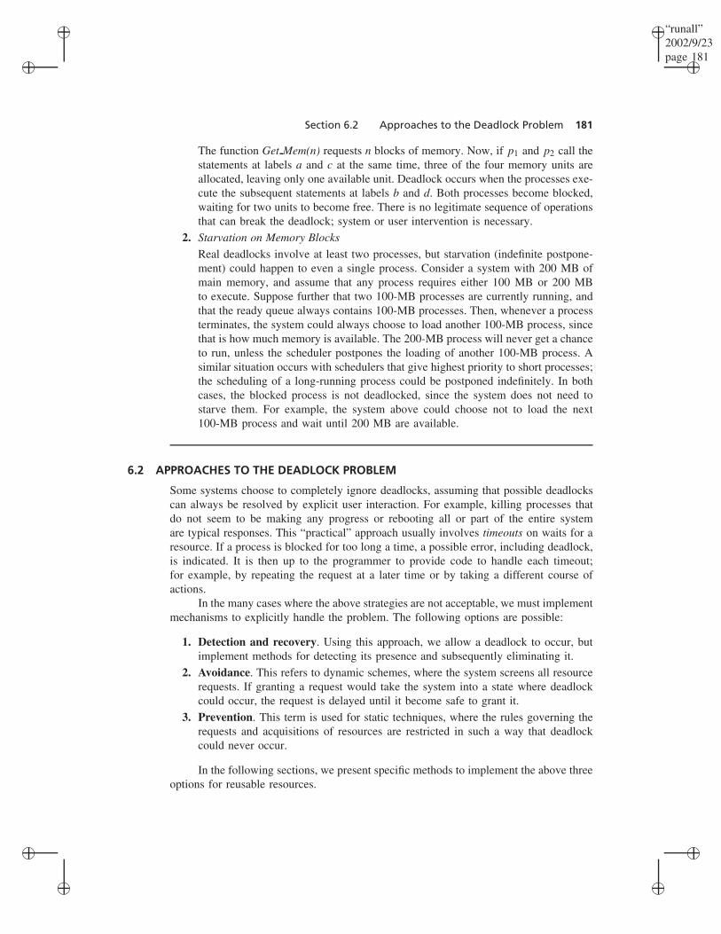
The function Get Mem(n) requests n blocks of memory. Now, if p1 and p2 call thestatements at labels a and c at the same time, three of the four memory units areallocated, leaving only one available unit. Deadlock occurs when the processes exe-cute the subsequent statements at labels b and d. Both processes become blocked,waiting for two units to become free. There is no legitimate sequence of operationsthat can break the deadlock; system or user intervention is necessary.
2. Starvation on Memory Blocks
Real deadlocks involve at least two processes, but starvation (indefinite postpone-ment) could happen to even a single process. Consider a system with 200 MB ofmain memory, and assume that any process requires either 100 MB or 200 MBto execute. Suppose further that two 100-MB processes are currently running, andthat the ready queue always contains 100-MB processes. Then, whenever a processterminates, the system could always choose to load another 100-MB process, sincethat is how much memory is available. The 200-MB process will never get a chanceto run, unless the scheduler postpones the loading of another 100-MB process. Asimilar situation occurs with schedulers that give highest priority to short processes;the scheduling of a long-running process could be postponed indefinitely. In bothcases, the blocked process is not deadlocked, since the system does not need tostarve them. For example, the system above could choose not to load the next100-MB process and wait until 200 MB are available.
6.2 APPROACHES TO THE DEADLOCK PROBLEM
Some systems choose to completely ignore deadlocks, assuming that possible deadlockscan always be resolved by explicit user interaction. For example, killing processes thatdo not seem to be making any progress or rebooting all or part of the entire systemare typical responses. This “practical” approach usually involves timeouts on waits for aresource. If a process is blocked for too long a time, a possible error, including deadlock,is indicated. It is then up to the programmer to provide code to handle each timeout;for example, by repeating the request at a later time or by taking a different course ofactions.
In the many cases where the above strategies are not acceptable, we must implementmechanisms to explicitly handle the problem. The following options are possible:
1. Detection and recovery. Using this approach, we allow a deadlock to occur, butimplement methods for detecting its presence and subsequently eliminating it.
2. Avoidance. This refers to dynamic schemes, where the system screens all resourcerequests. If granting a request would take the system into a state where deadlockcould occur, the request is delayed until it become safe to grant it.
3. Prevention. This term is used for static techniques, where the rules governing therequests and acquisitions of resources are restricted in such a way that deadlockcould never occur.
In the following sections, we present specific methods to implement the above threeoptions for reusable resources.

“runall”2002/9/23page 182
�
�
�
�
�
�
�
�
182 Chapter 6 Deadlocks
6.3 A SYSTEM MODEL
We first present a graph model as a convenient notation for the process-resource stateof a system, for the changes that occur as a result of resource requests, allocations, andreleases, and for defining specific deadlock-related states. Our deadlock algorithms aredirectly based on the model.
6.3.1 Resource Graphs
To be able to reason about deadlocks, we must have a representation for processes,resources, and their relationships in the system. We will represent the state of the systemby a directed graph, called the resource graph. All processes and resource classes arerepresented as vertices, and allocations and requests are represented as directed edges.Thus, at any given point in time, a resource graph captures all current allocations ofresources to processes, and all current requests by processes for resources. The graphconsists of the following components:
• Processes. Each process pi (1 ≤ i ≤ n) is a vertex represented as a circle. Forexample, the graph in Figure 6-1 shows a system consisting of three processes, p1,p2, and p3.
• Resources. Each resource class Rj (1 ≤ j ≤ m) is a vertex represented as arectangle. Each individual (indistinguishable) resource unit within that class isrepresented as a small circle inside the rectangle. The sample graph in Figure 6-1shows two resource classes, R1 and R2; R1 consists of two units, and R2 consistsof three.
• Resource requests. A request by a process pi for a unit of a resource Rj isrepresented as a directed edge (pi → Rj ); this is called a request edge. Processp1 of Figure 6-1 has no current requests, process p2 is requesting two units of R2,and process p3 is requesting one unit of R1.
• Resource allocations. An allocation of a resource unit of class Rj to a processpi is represented as a directed edge (Rj → pi); this is called an allocation edge.Each allocation edge is connected to one of the circles within the class to indicatethat the unit is currently unavailable to other processes. In Figure 6-1 process p1holds one unit of each resource class, p2 holds one unit of R1, and process p3holds two units of R2.
R1 R2
p1 p2 p3
FIGURE 6-1. A resource graph.
“runall”2002/9/23page 183
�
�
�
�
�
�
�
�
Section 6.3 A System Model 183
6.3.2 State Transitions
Each resource graph represents a particular state of the system. It captures all currentallocations and pending requests by all processes. The system state changes to a newstate whenever a process requests, acquires, or releases a resource. These are the onlypossible operations, since no other action can affect the system with respect to deadlock.The three operations are defined as follows:
1. Request. Any process pi in a given state may request additional resource units ofany resource class Rj . The request operation changes the state of the system to anew state that contains the additional request edges (pi → Rj ).
Any request is subject to the following restrictions:
• The requesting process pi currently has no request edges from pi to anyresource classes. This condition represents the fact that a process is blockedfrom the time it issues a request until the request is granted. Consequently,the process cannot execute any operations during that time.
• The number of edges between pi and Rj (both request and allocation edges)must never exceed the total number of units in Rj . Otherwise, the requestcould never be satisfied and the process would be blocked forever.
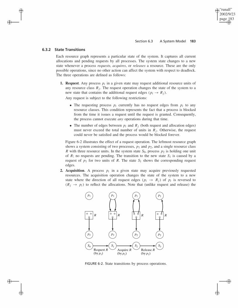
Figure 6-2 illustrates the effect of a request operation. The leftmost resource graphshows a system consisting of two processes, p1 and p2, and a single resource classR with three resource units. In the system state S0, process p2 is holding one unitof R; no requests are pending. The transition to the new state S1 is caused by arequest of p1 for two units of R. The state S1 shows the corresponding requestedges.
2. Acquisition. A process pi in a given state may acquire previously requestedresources. The acquisition operation changes the state of the system to a newstate where the direction of all request edges (pi → Rj ) of pi is reversed to(Rj → pi) to reflect the allocations. Note that (unlike request and release) the
p1
p2
Request R(by p1)
Acquire R(by p1)
Release R(by p1)
S0
R
p1
p2
S1
R
p1
p2
S2
R
p1
p2
S3
R
FIGURE 6-2. State transitions by process operations.

“runall”2002/9/23page 184
�
�
�
�
�
�
�
�
184 Chapter 6 Deadlocks
acquisition operation is not issued by the process pi itself, but rather represent therequest granting action taken by the resource manager. In fact, pi is blocked fromthe time it issues a request until the acquisition is completed.
Any acquisition is subject to the following restriction:
• All outstanding requests of pi must be satisfiable. That means, there must bea free resource (small circle inside Rj ) for every request edge (pi → Rj ).This guarantees that the process gets all its requested resources, or it remainsblocked. The reason for disallowing partial allocations is that it simplifies thedeadlock detection algorithms.
Consider again Figure 6-2. It shows that in state S2, the process p1 acquires the twopreviously requested units of R; the two request edges in S1 change to allocationedges in the new state S2.
3. Release. A process pi in a given state may release any previously acquired resourceunits. The release operation changes the state of the system to a new state wherethe allocation edges (Rj → pi) corresponding to the released resource units aredeleted. Any release is subject to the following restrictions:
• The process pi currently has no request edges from pi to any resource class.This is the same condition as in the case of the request operation.
• The process can release only those units it is currently holding; i.e., theremust be an allocation edge (Rj → pi) for any resource units being released.
The last part of Figure 6-2 illustrates the effect of a release operation. Process p1releases one of the previously acquired units of R.
6.3.3 Deadlock States and Safe States
Consider again the three state transitions shown in Figure 6-2. Note that these do notrepresent the only possible sequence of state changes for this system. The set of possiblestates the system can enter depends on the operations the processes can perform in agiven state. For example, in state S0 of Figure 6-2, p2 could release the unit of R it isholding, leading to a new state with no edges. Alternately, p1 could choose to requestonly one unit of R, or possibly all three; each choice would lead to a new system state.We do not generally know which path a given process may take through its code. Wealso do not know the order in which processes will be interleaved. But there is a finiteset of state the system may potentially enter. Our ultimate goal is to identify (or prevent)those states containing deadlocked processes. We first define the following key terms:
• A process is blocked in a given state if it cannot cause a transition to a new state;i.e., the process can neither request, acquire, or release any resources in that state,because some of the restrictions imposed on these operations are not satisfied.Assume, for example, that process p1 in state S0 of Figure 6-2 requests three unitsof R instead of just two. It would become blocked in the new state until p2 releasedthe one unit it is currently holding.
• A process is deadlocked in a given state S if it is blocked in S and if no matterwhat operations (state changes) occur in the future, the process remains blocked.Assume, for example, that in the state S3 of Figure 6-2, process p1 requests two
“runall”2002/9/23page 185
�
�
�
�
�
�
�
�
Section 6.3 A System Model 185
more units or R, and in the next transition, process p2 also requests two moreunits or R. Both processes would become blocked and remain blocked forever,i.e., deadlocked.
• A state is called a deadlock state if it contains a deadlocked process. Note that acycle in the resource graph is a necessary condition for deadlock.
• A state S is a safe state if for all states S′ that can be reached from S using anysequence of valid request, acquire, and release operations, S′ is not a deadlockstate.
EXAMPLE: Reachable States of a System
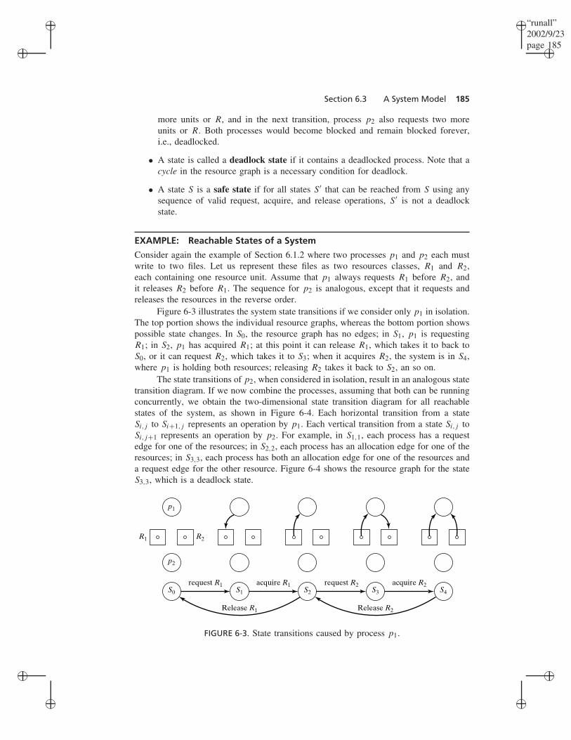
Consider again the example of Section 6.1.2 where two processes p1 and p2 each mustwrite to two files. Let us represent these files as two resources classes, R1 and R2,each containing one resource unit. Assume that p1 always requests R1 before R2, andit releases R2 before R1. The sequence for p2 is analogous, except that it requests andreleases the resources in the reverse order.
Figure 6-3 illustrates the system state transitions if we consider only p1 in isolation.The top portion shows the individual resource graphs, whereas the bottom portion showspossible state changes. In S0, the resource graph has no edges; in S1, p1 is requestingR1; in S2, p1 has acquired R1; at this point it can release R1, which takes it to back toS0, or it can request R2, which takes it to S3; when it acquires R2, the system is in S4,where p1 is holding both resources; releasing R2 takes it back to S2, an so on.
The state transitions of p2, when considered in isolation, result in an analogous statetransition diagram. If we now combine the processes, assuming that both can be runningconcurrently, we obtain the two-dimensional state transition diagram for all reachablestates of the system, as shown in Figure 6-4. Each horizontal transition from a stateSi,j to Si+1,j represents an operation by p1. Each vertical transition from a state Si,j toSi,j+1 represents an operation by p2. For example, in S1,1, each process has a requestedge for one of the resources; in S2,2, each process has an allocation edge for one of theresources; in S3,3, each process has both an allocation edge for one of the resources anda request edge for the other resource. Figure 6-4 shows the resource graph for the stateS3,3, which is a deadlock state.
S0 S1 S2 S3 S4
request R1
Release R1 Release R2
request R2acquire R1 acquire R2
p1
p2
R1 R2
FIGURE 6-3. State transitions caused by process p1.

“runall”2002/9/23page 186
�
�
�
�
�
�
�
�
186 Chapter 6 Deadlocks
S0,0
S0,1
S0,2
S0,3
S0,4 S1,4
Release R
2R
elease R1
Request R
2A
cquire R2
Request R
1A
cquire R1
S1,0
S1,1
S1,2
S1,3
S2,0
S2,1
S2,2
S2,3
S3,0
S3,1
S3,2
S3,3
S4,0
S4,1
p1
p2
R2R1
Request R1 Acquire R1 Request R2 Acquire R2
Release R1 Release R2
FIGURE 6-4. State transitions caused by p1 and p2.
The state transition diagram in Figure 6-4 also illustrates the other concepts intro-duced above:
• p1 is blocked (but not deadlocked) in S3,2 and S1,4; there is no horizontal transitionleading from these states. Similarly, p2 is blocked (but not deadlocked) in S2,3 andS4,1.
• Both processes are deadlocked in S3,3, since there is no transition, horizontal orvertical, leading from this state; i.e., S3,3 is a deadlock state.
• No state is safe, since the deadlock state S3,3 is reachable from any other state.
6.4 DEADLOCK DETECTION
To detect whether a given state S is a deadlock state, it is necessary to determine whetherthe processes that are blocked in S will remain blocked forever. This can be accomplishedusing a technique called graph reduction, which mimics the following execution scheme:
“runall”2002/9/23page 187
�
�
�
�
�
�
�
�
Section 6.4 Deadlock Detection 187
First, all requests satisfiable in state S for unblocked processes are granted, and therequesting processes continue to completion without requesting any further resources.Prior to termination, they release all their resources. These actions may wake up previ-ously blocked processes, which then proceed to completion in the same manner. This isrepeated until there are either no processes left, i.e., all processes have been terminated,or all remaining processes are blocked. In the latter case, the original state S is a deadlockstate.
We now consider the graph reduction algorithm in more detail.
6.4.1 Reduction of Resource Graphs
Given a resource graph representing a system state, repeat the following steps until thereare no unblocked processes remaining:
1. Select an unblocked process p.
2. Remove p, including all its request and allocation edges.
A resource graph is called completely reducible if, at the termination of the abovereduction sequence, all process nodes have been deleted. We can now obtain the followingimportant results in deadlock detection:
• S is a deadlock state if and only if the resource graph of S is not completelyreducible.
• All reduction sequences of a given resource graph lead to the same final graph.That means, in step 1 of the reduction sequence above, it does not matter whichunblocked process is selected.
The two results lead to an efficient algorithm for deadlock detection. They implythat, given a resource graph for a state S, we can apply any sequence of reductions. If,at the end, the graph is not completely reduced, S is a deadlock state.
EXAMPLE: Graph Reduction
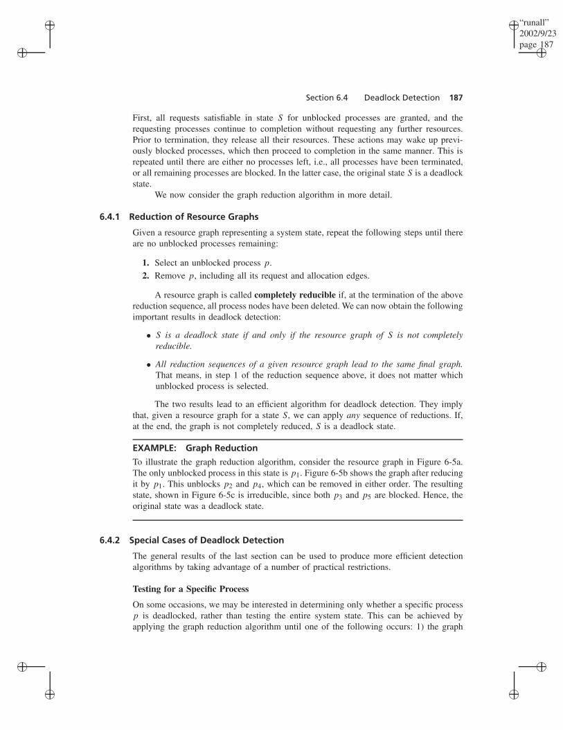
To illustrate the graph reduction algorithm, consider the resource graph in Figure 6-5a.The only unblocked process in this state is p1. Figure 6-5b shows the graph after reducingit by p1. This unblocks p2 and p4, which can be removed in either order. The resultingstate, shown in Figure 6-5c is irreducible, since both p3 and p5 are blocked. Hence, theoriginal state was a deadlock state.
6.4.2 Special Cases of Deadlock Detection
The general results of the last section can be used to produce more efficient detectionalgorithms by taking advantage of a number of practical restrictions.
Testing for a Specific Process
On some occasions, we may be interested in determining only whether a specific processp is deadlocked, rather than testing the entire system state. This can be achieved byapplying the graph reduction algorithm until one of the following occurs: 1) the graph

“runall”2002/9/23page 188
�
�
�
�
�
�
�
�
188 Chapter 6 Deadlocks
(a)
R1 R2 R3
p1
p4 p5
p2 p3
(b)
R1 R2 R3
p4 p5
p2 p3
(c)
R1 R2 R3
p4
p3
FIGURE 6-5. Graph reduction.
can be reduced by p, which implies that p is not blocked and hence not deadlocked; and2) the graph is irreducible, in which case p is deadlocked. In both cases, the algorithmstops at this point.
Continuous Deadlock Detection
Testing for deadlock can be accomplished more efficiently if it is done on a continuousbasis. If we know that the current state S is not deadlocked, then the next state S′ is adeadlock state if and only if the operation that caused the transition was a request, and theprocess p that performed the operation is deadlocked in S′. In other words, a deadlockin S′ can only be caused by a request that cannot be granted immediately. Thus, we onlymust check the specific process p; if p can be reduced, S′ is not a deadlock state.
Immediate Allocations
Some resource allocators adopt the simple policy that all satisfiable requests are alwaysgranted immediately. If this is the case, a resource graph never contains any satisfiablerequest edges, since these are immediately turned into allocation edges. Such systemstates are referred to as expedient. For example, the state of Figure 6-5a is not expedientbecause p1 is not blocked, and its request can be granted immediately. If we allocate aunit of R1 to p1, the state then becomes expedient. This yields a simpler condition fordeadlock detection:
If a system state is expedient, then a knot in the corresponding resource graph implies adeadlock.
A knot in a directed graph is defined as a subset of nodes that satisfy the followingtwo conditions: 1) Every node within the knot is reachable from every other node within

“runall”2002/9/23page 189
�
�
�
�
�
�
�
�
Section 6.4 Deadlock Detection 189
the knot; and 2) a node outside the knot is not reachable from any node inside the knot.For example, consider Figure 6-5a again. If we delete the edge R2 → p1, the graph hasa knot {R2, p3, R3, p5}. If we also change the edge p1 → R1 to R1 → p1, the statebecomes expedient, and it contains a deadlock.
To understand the intuition behind the above deadlock-detection condition, considera resource graph containing a knot K . All processes within K must have pending requests,because each node must have an outgoing edge. Furthermore, they may only be requestingresources within K , since no edges may lead outside of K . If the state is expedient, noneof the pending requests can be satisfiable, and hence all the processes must be deadlocked.Note that a knot is sufficient for deadlock, but not a necessary condition. The expedientstate that we produced from Figure 6-5a by reversing the edge p1 → R1, for example,does not have a knot but is still deadlocked.
Single-Unit Resources
In many situations, all resource classes are limited to having only a single unit. Commonexamples are files and locks. With this restriction, the existence of a simple cycle in theresource graph implies a deadlock. Thus, in this case, a cycle is both a necessary andsufficient condition for deadlock.
To show why this condition is sufficient, assume that the graph contains a cycle C.Since every process within C must have an entering and exiting edge, it must have anoutstanding request for a resource in C and must hold resources in C. Therefore, everyprocess in C is blocked on a resource in C that can be made available only by anotherprocess in C. Hence, all the processes in the cycle are deadlocked.
Thus, to detect a deadlock in systems with single-unit resources, we only must testthe resource graph for cycles. There are well-known algorithms that can accomplish thatin O(n2) time, where n is the number of nodes.
A single-unit resource class can have only a single allocation edge attached to it.This allows us to present the resource graph in a simplified form. We omit all resourceclasses and, instead, point all request edges directly at the process currently holding theresource. Such a graph is called a wait-for graph because an edge (pi → pj ) indicatesthat process pi is blocked on a resource currently held by pj ; i.e., pi is waiting for pj
to release the resource. Then, more simply, a cycle in the wait-for graph is a necessaryand sufficient condition for deadlock.
EXAMPLE: Wait-For Graph
Figure 6-6 illustrates the concept. In Figure 6-6a, processes p1 and p2 are requestinga resource currently held by p3. In turn, p3 is requesting a resource currently held byp4. Figure 6-6b shows the corresponding wait-for graph: p1 and p2 are waiting for p3,which is waiting for p4.
6.4.3 Deadlock Detection in Distributed Systems
Wait-for graphs as defined in the previous section are the basis of deadlock detectionin distributed systems restricted to single-unit resources. The added difficulty is that nosingle machine has a complete picture of all resource requests or allocations. Thus, the

“runall”2002/9/23page 190
�
�
�
�
�
�
�
�
190 Chapter 6 Deadlocks
(a)
p1
p3
p2
R1 R2
p4
(b)
p1
p3 p4
p2
FIGURE 6-6. A wait-for graph.
wait-for graph itself is distributed; some edges cross the boundary between differentmachines.
Let each machine have its own local coordinator, responsible for maintaining thelocal portion of the wait-for graph. To detect deadlock, we must check for cycles in theglobal wait-for graph. But since cycles can span multiple machines, the coordinators mustcooperate by exchanging information with one another to detect such global cycles. Thiscan be done in two different ways, either through a central coordinator or in a distributedapproach.
Central Coordinator Approach
The simplest way to detect cycles in the global wait-for graph is to mimic a centralizedsystem. One of the local coordinators is designated as the central coordinator. It collectsthe local wait-for graphs from all other coordinators, assembles them into a completeglobal graph, and analyzes the global graph for the presence of cycles. The local graphscan be sent to the global coordinator whenever an edge is added or removed, or (lessfrequently) by grouping together multiple changes to reduce message traffic.
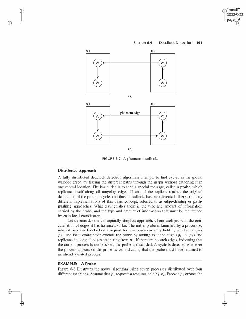
The centralized approach to deadlock detection, although straightforward to imple-ment, has two main drawbacks. First, the global coordinator becomes a performancebottleneck and a single point of failure. Second, it is prone to detecting nonexistingdeadlocks, referred to as phantom deadlocks. To illustrate how this can happen, con-sider a system with two machines, M1 and M2, each holding two processes. Figure 6-7ashows the global wait-for graph. This indicates that p1 is currently holding a resourcethat p2 is requesting; p2, in turn, is holding a resource that p3 (on machine M2) isrequesting; and p3 is holding a resource that p4 is requesting. Assume now that p1requests a resource held by p4, which adds the edge (p1 → p4). Concurrently, p3 onM2 times out on its wait, which removes its waiting edge for p2, i.e., (p3 → p2). If theglobal coordinator receives the update from M1 first, it will construct the graph shown inFigure 6-7b, and, consequently, it will report a deadlock. In reality, no deadlock exists,since the actual wait-for graph does not contain the phantom edge (p3 → p2).
“runall”2002/9/23page 191
�
�
�
�
�
�
�
�
Section 6.4 Deadlock Detection 191
(a)
p1
p2
M1
p3
p4
M2
(b)
p1
p2
M1
p3
p4
M2
phantom edge
FIGURE 6-7. A phantom deadlock.
Distributed Approach
A fully distributed deadlock-detection algorithm attempts to find cycles in the globalwait-for graph by tracing the different paths through the graph without gathering it inone central location. The basic idea is to send a special message, called a probe, whichreplicates itself along all outgoing edges. If one of the replicas reaches the originaldestination of the probe, a cycle, and thus a deadlock, has been detected. There are manydifferent implementations of this basic concept, referred to as edge-chasing or path-pushing approaches. What distinguishes them is the type and amount of informationcarried by the probe, and the type and amount of information that must be maintainedby each local coordinator.
Let us consider the conceptually simplest approach, where each probe is the con-catenation of edges it has traversed so far. The initial probe is launched by a process pi
when it becomes blocked on a request for a resource currently held by another processpj . The local coordinator extends the probe by adding to it the edge (pi → pj ) andreplicates it along all edges emanating from pj . If there are no such edges, indicating thatthe current process is not blocked, the probe is discarded. A cycle is detected wheneverthe process appears on the probe twice, indicating that the probe must have returned toan already-visited process.
EXAMPLE: A ProbeFigure 6-8 illustrates the above algorithm using seven processes distributed over fourdifferent machines. Assume that p1 requests a resource held by p2. Process p1 creates the

“runall”2002/9/23page 192
�
�
�
�
�
�
�
�
192 Chapter 6 Deadlocks
p1 p2 p3p1 p2 p1 p2 p3
p4 p5p1 p2 p3 p4 p5
p1 p2 p3 p4 p5 p1
p1 p2 p3 p4
p1 p2 p3 p7
M1
p7
M3
p1 p2 p3 p4 p5 p6
p1 p2 p3 p4 p5 p6
p4
p6
M4
M2
FIGURE 6-8. A probe to detect cycles.
initial probe containing the edge p1 → p2. Since p2 waits for p3, the probe is extendedto p1 → p2 → p3. p3 is waiting for p4 and p7, and consequently, replicates the probealong the two different paths, as shown. The one carrying p1 → p2 → p3 → p7 isdiscarded on machine M3, since p7 is not blocked. On the other hand, the other probecontinues through p4 to p5. At p5, the probe is again replicated. The one containingp1 → p2 → p3 → p4 → p5 → p1 closes the cycle upon reaching machine M1. p1appears twice on the path—once as the initiator of the original probe and a second timeas its recipient. Thus, the coordinator on M1 detects a deadlock. In a similar manner, thecoordinator on M2 can detect the other cycle in the graph by noticing that p4 appearstwice on the probe p1 → p2 → p3 → p4 → p5 → p1 → p4 → p4.
The main drawback of the above implementation is that the probe’s length isunbounded. That may not be a serious problem in practice, since the paths in the wait-for graphs are typically short. Nevertheless, there are approaches where the probe lengthcan be kept constant at the expense of maintaining additional information about thealready-known dependencies by each local coordinator (Chandy, Misra, Haas 1983).
6.5 RECOVERY FROM DEADLOCK
A deadlock always involves a cycle of alternating process and resource nodes in theresource graph. The two general approaches to recovery are process termination andresource preemption. In the first case, nodes and edges of the resource graph are elim-inated. The second strategy involves edge deletions only. In both cases, the goal is tobreak the deadlock cycle.
6.5.1 Process Termination
The simplest and crudest recovery algorithms terminate all processes involved in thedeadlock. This approach is unnecessarily wasteful, since, in most cases, eliminating asingle process is sufficient to break the deadlock. Thus, it is better to terminate processesone at a time, release their resources, and at each step check if the deadlock still persists.

“runall”2002/9/23page 193
�
�
�
�
�
�
�
�
Section 6.5 Recovery from Deadlock 193
This is repeated until the deadlock is eliminated, or, in the worst case, until all but oneof the originally deadlocked processes must be liquidated.
With this incremental method, we must decide on the order in which the processeswill be terminated. Picking the processes at random is the easiest solution, but it is morerational to consider the cost of terminating different processes. Termination cost mayinvolve a combination of the following:
1. The priority of the process. This metric is similar to that used for process schedul-ing. It may involve the process type (e.g., real-time, interactive, or batch), its CPUor memory requirements, and other metrics.
2. The cost of restarting the process. Many processes maintain very little state andcan easily be restarted. This includes most interactive processes, such as the usershell, Internet browsers, or even text editors (provided the edited files are beingsaved periodically). In contrast, other applications cannot be “resumed” but must berepeated from the beginning. This includes, for example, scientific computations,which may run for hours or even days in batch mode. Terminating such applicationsis not only costly but also frustrating for the users.
3. The current state of the process. Many processes cooperate with others in a varietyof ways, thus killing one process may seriously impact others that depend on it.For example, killing the consumer or the producer process in a producer-consumerscenario will leave the other process hanging. Similarly, killing a process in themiddle of a CS will deadlock other processes that compete for the same CS. Finally,some operations are not idempotent, i.e., cannot be repeated without side effects.For example, appending data to a file cannot simply be repeated by rerunning akilled process.
In general, choosing the best sequence of processes to terminate is highly dependenton the particular system and its applications.
6.5.2 Resource Preemption
Resource preemption means taking away the contested resources from one or more ofthe deadlocked processes. This can be done in one of two ways. First, some resourcesmay lend themselves to direct preemption; i.e., the system temporarily deallocates theresource, lets other processes use it, and gives it back to the original process. Fewresources can be handled in this way transparently. For example, temporarily reallocatinga printer in the middle of a print job would result in interleaved pages from multipleprocesses. Main memory is one of the few resources that can be preempted transparently,by temporarily swapping a process or some of its data to disk, and reloading it later whenmemory is again available.
An indirect form of resource preemption is achieved by process rollback. Somesystems take periodic snapshots of processes, called checkpoints, to achieve fault toler-ance. In the case of a crash, the process does not need to be restarted from its beginning.Instead, the process can be rolled back by restoring its last checkpoint and resuming itsexecution from there. We can use the same mechanism for resource preemption. To takeaway a resource from a process, we can roll it back to a checkpoint during which ithad not acquired this resource yet. After resuming execution from this point, the process

“runall”2002/9/23page 194
�
�
�
�
�
�
�
�
194 Chapter 6 Deadlocks
would repeat the earlier request for the resource, which, in the meantime, could be usedby other processes.
6.6 DYNAMIC DEADLOCK AVOIDANCE
The previous section focused on detecting deadlocks and eliminating them once theyoccur. An entirely different strategy is to prevent deadlocks from developing in the firstplace. When this is done through rules checked and enforced at runtime, the approach isreferred to as deadlock avoidance.
6.6.1 Claim Graphs
The basic principle of deadlock avoidance is to delay the acquisition of resources thatmight cause the system to enter a deadlock state in the future. This can be determined ifinformation about future process resource needs is available. Generally, processes do notknow which resources they will need in the future. However, they can specify an upperbound on their needs, called the maximum claim. This is the largest number of units ofeach resource that the process will ever need at any one time.
The maximum claim of a process can be represented as a claim graph, which is anextension of the general resource graph used for deadlock detection. A claim graph, inaddition to showing processes, resources, request edges, and allocation edges, contains aset of potential request edges. In the initial system state, the number of such edges (pi →Rj ) represent the maximum number of units of resource Rj that process pi will ever need.
Each potential request edge may, in the future, be transformed into an actual requestedge and, subsequently, into an assignment edge. But the total number of edges betweenthe process pi and resource class Rj (i.e., the sum of request, allocation, and claimedges) will always remain the same.
EXAMPLE: Claim Graph
Figure 6-9 shows an example of a claim graph in the initial system state S0, and itstransformation into other states as the result of operations by the two processes. Therequest and allocation edges are shown as before; the added claim edges are representedby dashed lines.
The graph shows that process p1 may request, at most, two units of R at any giventime, whereas p2 may request all three. The first operation is a request by p2 for oneunit of R. The new state S1 shows one of the claim edges transformed into an actualrequest edge. The request is granted, resulting in state S2. The next operation is a requestby p2 for two units of R (in state S3), which is also granted (in state S4). At this point,p2 could request one of two more units of R, which would block the process until theunits were released by p1.
6.6.2 The Banker’s Algorithm
Claim graphs may be used for dynamic deadlock avoidance. This is achieved by disallow-ing any acquisition operations unless the resulting claim graph is completely reducible.The fact that the claim graph can be completely reduced means that the worst case of all

“runall”2002/9/23page 195
�
�
�
�
�
�
�
�
Section 6.6 Dynamic Deadlock Avoidance 195
p1
Request R(by p2)
Acquire R(by p2)
Request R(by p1)
Acquire R(by p1)
p2
p1
p2
p1
p2
p1
p2
p1
p2
S0 S1 S2 S3 S4
R R R R R
FIGURE 6-9. State transitions using claim graphs.
possible future requests could be handled. That means, even if all processes requestedthe remainders of their claims, all requests could still be satisfied. The following theoremhas been proven formally:
If acquisition operations that do not result in a completely reducible claim graph areprohibited, any system state is safe.
This theorem is the basis of deadlock-avoidance algorithms, the best known of whichis the banker’s algorithm (Dijkstra 1968). It takes its name from an analogy to bankingsystems, where resource classes correspond to currencies, allocations correspond to loans,and maximum claims are considered the credit limits. Deadlock prevention is accomplishedby the “banker,” which grants or delays any request in a given state S as follows:
1. Assume the request in state S is granted, i.e., temporarily change the request edge(s)into the corresponding acquisition edge(s); the new tentative state is S′.
2. Reduce the claim graph of S′. That means, treat all claim edges in S′ as actualrequest edges and reduce the resulting graph.
3. If the graph is completely reducible, grant the original request, i.e., accept S′ as thenew state and continue; otherwise, delay the acquisition, i.e., revert to the originalstate S and keep the request as pending.
EXAMPLE: The Banker’s Algorithm
To illustrate the working of the banker’s algorithm, consider the claim graph in Figure 6-10a, which shows the state of the same system as Figure 6-1, but at an earlier time. Therequests by p1 and p2 for one unit of R1 each have not been granted yet. Thus, all threeprocesses have pending requests for one unit of R1. The original resource graph also hasbeen augmented by the claim edges of each process, shown as dashed lines. The task of thebanker’s algorithm is to decide which of the three pending requests for R1 can safely begranted.

“runall”2002/9/23page 196
�
�
�
�
�
�
�
�
196 Chapter 6 Deadlocks
p1 p2
R1 R2
p3
(a)
p1 p2
R1 R2
p3
(b)
p1 p2
R1 R2
p3
(c)
FIGURE 6-10. Deadlock avoidance using the banker’s algorithm.
Figure 6-10b shows the new graph should p1’s request be granted. The resultinggraph is completely reducible (first by p1, then by p3, and finally by p2). Hence, thisrequest could be granted in this state. The request by p3 also results in a completelyreducible graph and may be granted. On the other hand, the request by p2 results in thegraph shown in Figure 6-10c. If we interpret all claim edges as actual request edges, thenall three processes are blocked, and the graph is not reducible. To prevent such a situationfrom developing, the request by p2 must be delayed until it becomes safe to grant it.
Special Case: Single-Unit Resources
When all resource classes contain only a single unit, the reducibility of the claim graphcan be tested much more efficiently. This is based on the following observation: a claimgraph becomes irreducible only when an acquisition creates a cycle in the claim graph.Thus, a simple path-tracing algorithm from the acquiring process can be employed fordeadlock prevention.

“runall”2002/9/23page 197
�
�
�
�
�
�
�
�
Section 6.7 Deadlock Prevention 197
EXAMPLE: Single-Unit Resources
Figure 6-11a illustrates this idea using a simple system of two processes and tworesources. The pending request by p2 for R1 must not be granted, since doing so wouldclose the (directed) cycle p1 → R1 → p2 → R2 → p1.
p1
R1 R2
p2
(a) (b)
FIGURE 6-11. Deadlock avoidance with single-unit resources.
We also can easily test for safeness of states in single-unit resource graphs. This isbased on the following observation: a directed cycle can develop only if the graph containsan undirected cycle. In other words, if we disregard the direction of all edges and determinethat the graph contains no undirected cycles, then no directed cycle will develop in such aclaim graph. Consequently, in this situation, all states are safe, and there is no possibility ofdeadlock. Note that this only must be checked once, when the claim graph is first created.Thus, dynamic deadlock avoidance turns into a single static test.
EXAMPLE: Safe StatesFigure 6-11b illustrates a system where all states are safe. If we ignore the direction ofthe claim edges, we see that no cycle can be formed, since the claim edges are a supersetof all possible future request or acquisition edges.
6.7 DEADLOCK PREVENTION
Dynamic deadlock avoidance relies on runtime checks to ensure the system never entersan unsafe state. These are performed by the system (the resource manager) that is respon-sible for granting or delaying any given request. On the other hand, deadlock preventionrelies on imposing additional rules or conditions on the system so that all states are safe.Thus, prevention is a static approach, where all processes must follow certain rules forrequesting or releasing resources.
By examining the general form of a resource graph, we can identify the followingthree structural conditions that must hold for deadlock to occur:
1. Mutual exclusion. Resources are not sharable; i.e., there is, at most, one allocationedge from any resource unit to a process in the resource graph.

“runall”2002/9/23page 198
�
�
�
�
�
�
�
�
198 Chapter 6 Deadlocks
2. Hold and wait. A process must be holding a resource and requesting another;i.e., there must be an allocation edge from a resource unit to a process p1, and arequest edge from p1 to another resource unit. The two units can be within thesame resource class or within different classes.
3. Circular wait. At least two processes must be blocked waiting for each other;i.e., the graph must contain a cycle involving at least two processes and at leasttwo resource units, such that each process holds one of the units and is requestinganother.
The elimination of any of these three conditions would make it structurally impos-sible for deadlock to occur.
6.7.1 Eliminating the Mutual-Exclusion Condition
If all resources could be shared (accessed concurrently), no process would block on aresource, and no deadlock would occur. Some resources that might be used nonexclu-sively in a shared fashion are pure program code, read-only data files or databases, andclocks. Unfortunately, mutual exclusion is a fundamental requirement for correct use ofmany resource types, and this condition cannot generally be eliminated. For example,files cannot usually be written into by multiple processes at the same time in a mean-ingful way. Similarly, database transactions require exclusive access to records to ensuredata consistency.
In some instances, it is possible to circumvent the mutual exclusion requirement bytransforming nonsharable resources into sharable ones. The prime example is spooling ofoutput, which was briefly discussed in the Introduction. Printers or other output devicesalways must be accessed by only one process at a time to prevent interleaving of output.To avoid unnecessary blocking of processes waiting for output, many OSs provide virtualdevices, implemented as software files, into which processes may direct their output.When the complete output sequence is available, it is sent to the actual hardware printer,and the process continues without blocking.
6.7.2 Eliminating the Hold-and-Wait Condition
The simplest way to eliminate this condition is to insist that every process requests allresources it will ever need at the same time. A process with resources already allocatedto it will never be blocked because it cannot make any further requests. It will eventuallyrelease all its resources (not necessarily at the same time), which may unblock otherprocesses. But a given process will have either assignment edges or request edges, butnever both together. Deadlock is therefore impossible, and every state is safe.
The main drawback of this simple policy is poor resource utilization—resourcesmust be allocated well ahead of their actual use and be unavailable to other processesfor possibly long periods of time. Resources also may be requested unnecessarily inanticipation of a use that does not materialize.
A more flexible approach is allow processes to request resources as they needthem, but to always release all resources they are currently holding, prior to making anynew request. This may result in having to repeatedly request and release frequently usedresources. Assume, for example, that a process needs either resources R1 and R2, or

“runall”2002/9/23page 199
�
�
�
�
�
�
�
�
Section 6.7 Deadlock Prevention 199
R1 and R3, but never R2 and R3 together. To eliminate the hold-and-wait condition,the processes cannot simply release and request R2 or R3 as needed, while keeping R1.Instead, the process must release both R1 and R2, prior to requesting R1 and R3, andvise versa.
Yet a third alternative is to give each process the ability to test whether a neededresource R is currently available. If not, the process must release all other resources it iscurrently holding, prior to waiting for the unavailable resource R to become free. Noneof these alternatives is really satisfactory.
6.7.3 Eliminating the Circular-Wait Condition
A cycle in the resource graph can develop only when processes request the same resourcesbut in a different order. This can be prevented if all processes request all resources in thesame order. Since it is not known, generally, which resources will be needed by whichprocess, we assign a sequential ordering, SEQ, to all existing resource classes, such thatSEQ(Ri) �= SEQ(Rj ) for all i �= j . In other words, any process can test whether agiven resource precedes or succeeds another resource according to the ordering SEQ.Processes are then allowed to request any subset of the existing resources as in the generalcase, but they must request them in the order prescribed by SEQ. When a process alreadyholds a resource Ri , it may only request resources Rj with a higher sequence number,i.e., resources where SEQ(Ri) < SEQ(Rj ).
EXAMPLE: Ordered Resources Policy
Assume a system with four resource classes, R1, R2, R3, and R4, where SEQ(R1) <
SEQ(R2) < SEQ(R3) < SEQ(R4). Figure 6-12 shows three processes competing forthese three resource classes. Process p1 has no outstanding requests and could requestunits from any of the four classes. Process p2 is already holding a unit from the highestclass, R4, and is not allowed to make further requests. Process p3 holds units from R1,R2, and R3; thus, the only additional resources it could request are from class R4.
p1 p2 p3
R2R1 R4R3••• ••• ••• •••
FIGURE 6-12. Ordered resources policy.
By assigning the most expensive or scarce resources to the highest classes, therequests of the most valuable resources can be deferred until they are actually needed.Nevertheless, the overall resource utilization of this ordered resources policy is still notvery high, because some resources must be allocated well in advance of their need. This

“runall”2002/9/23page 200
�
�
�
�
�
�
�
�
200 Chapter 6 Deadlocks
policy was originally devised by Havender (1968) for the IBM OS called OS/360. It alsois used to prevent deadlock on monitor locks when using nested monitors, i.e., when aprocedure within one monitor calls a procedure within another monitor. These monitorsmust be called in a given order (Lampson and Redell 1980).
CONCEPTS, TERMS, AND ABBREVIATIONS
The following concepts have been introduced in this chapter. Test yourself by definingand discussing each keyword or phrase.
Banker’s algorithm KnotCentral coordinator LivelockCheckpoint Maximum claimCircular wait Ordered resource policyClaim graph Phantom deadlockConsumable resource Probe messageContinuous detection Reachable stateDeadlock Reducible graphDeadlock avoidance Resource graphDeadlock detection Reusable resourceDeadlock prevention RollbackDeadlock recovery Safe stateDeadlock state Single-unit resourceDistributed detection StarvationGraph reduction State of a systemHold and wait Wait-for graphs
EXERCISES
1. Consider the dining philosophers problem of Section 3.2. Assume there are threephilosophers, p1, p2, and p3 using three forks, f1, f2, and f3. The philosophers executethe following code:
p1() { p2() { p3() {while (1) { while (1) { while (1) {
P(f1); P(f1); P(f3);
P(f3); P(f2); P(f2);
eat; eat; eat;
V(f3); V(f2); V(f2);
V(f1) } V(f1) } V(f3) }} } }
(a) Is deadlock possible in this system?(b) Would deadlock be possible if we reversed the order of the P operations in process
p1, p2, or p3?(c) Would deadlock be possible if we reversed the order of the V operations in
process p1, p2, or p3?

“runall”2002/9/23page 201
�
�
�
�
�
�
�
�
Section 6.7 Deadlock Prevention 201
2. Consider the following reusable resource graph:
p1
R1 R2 R3 R4
p3
p2 p4
(a) Which processes are blocked?(b) Which processes are deadlocked?(c) Is the state a deadlock state?(d) Does the graph contain a knot? If so, list the nodes constituting the knot.
3. Consider three processes, p1, p2, and p3, executing asynchronously the followingsequences of code:
p1 p2 p3
......
...
P(x) P(y) P(z)...
... ← ...
P(z) ← P(y) P(x) ←...
......
V(x) V(z)...
...
V(z) V(x)
The arrow in each line indicates which instruction the corresponding process is cur-rently executing. All semaphores were initially set to 1.(a) Draw a reusable resource graph describing the above situation where each
semaphore is interpreted as a resource, and P and V operations represent requestsand releases of the resources.
(b) Reduce the graph as much as possible; does it represent a deadlock state?(c) If you could increase the number of units of any of the three resources, which
increase (if any) would resolve the deadlock?4. Using the definitions of Section 6.3.3, show that safeness of a state and deadlock are
not complementary; i.e., the statement “S is not a deadlock state” does not imply that“S is a safe state”.
5. The basic graph-reduction algorithm given in Section 6.4.1 is very inefficient. Thefirst step—finding an unblocked process during each iteration—requires a number ofoperations proportional to the number of processes. Develop a more efficient algorithmthat maintains a list of unblocked processes. At each iteration, a process is selectedfrom this list and removed from the graph. This reduction may, in turn, unblock otherprocesses, which are added to the list. Thus, finding an unblocked process is always asingle constant operation. (Hint: Maintain a counter for each process that records thenumber of resource classes the process is blocked on.)

“runall”2002/9/23page 202
�
�
�
�
�
�
�
�
202 Chapter 6 Deadlocks
6. Modify the state transition diagram of Figure 6-4 to reflect the following changes:(a) A process may release both resources at the same time.(b) A process will not release its first resource until it has acquired the second. Both
resources are then released at the same time.(c) Process p1 only needs resource R2.(d) Would the changes in (a), (b), or (c) eliminate the possibility of deadlock?
7. Two processes, p1 and p2, both need two single-unit resources, R1 and R2. Theprocesses repeatedly execute the following sequences (at unknown speeds):
p1: p2:
while(1) { while(1) {request R1; request R2;
request R2; request R1;
release R1; release R2;
release R2; release R1;...
...
} }(a) Assume first that process p2 is not executing. Draw the state transition diagram,
similar to Figure 6-3, where each state Si corresponds to the state i of p1. Inwhich state(s), if any, is p1 blocked and/or deadlocked?
(b) Now draw the state transition diagram for both processes, similar to Figure 6-4.Each system state Si,j represents the state i of p1 and the state j of p2. In whichstate(s), if any, is p1 blocked and/or deadlocked? In which state(s), if any, is p2blocked and/or deadlocked?
(c) For the state transition diagram of point (b) above, draw the resource graphscorresponding to the states S1,0, S1,1, S1,2, S1,3, S1,4, S1,5, S2,3, S3,3.
8. Consider the same two processes and resources as in Exercise 7, but assume nowthat both processes request R1 before R2. Draw the state transition diagram for thetwo processes, similar to Figure 6-4. In which state(s), if any, is p1 blocked and/ordeadlocked? In which state(s), if any, is p2 blocked and/or deadlocked?
9. Consider a system of three processes and a single-resource class with four units. Eachprocess needs at most two units. Show that the system is deadlock free, i.e., all statesare safe.
10. Consider a generalization of Exercise 9 where the system consists of n processes anda single-resource class with m units. Show that the system is deadlock free if the sumof all maximum needs of all processes is less than n+m units.
11. Prove the following by counterexamples:(a) A cycle is not a sufficient condition for deadlock.(b) A knot is not a necessary condition for deadlock in expedient state graphs.
12. Consider five processes, each running on a different machine. The wait-for graphcontains the following edges: p1→ p2, p2→ p3, p3→ p4, p1→ p5, p5→ p4.(a) Does this represent a deadlock state?(b) Assume process p5 times out, which removes the edge p5→ p4 from the graph.
At the same time, p4 requests a resource currently held by p1.i. Is the new state a deadlock state? If not, could a centralized coordinator
approach produce a phantom deadlock?ii. With a distributed algorithm, what probes could p4 receive in response to
making its request?(c) Repeat the previous problem, assuming that instead of p5, process p1 times out,
which removes its two edges from the graph.
“runall”2002/9/23page 203
�
�
�
�
�
�
�
�
Section 6.7 Deadlock Prevention 203
13. Consider a system that uses process rollback for recovery from deadlocks.(a) What are all the possible pieces of information that must be saved as part of a
process checkpoint?(b) Can the process be restarted completely transparently from a checkpoint? If not,
which actions performed or initiated by the process may be irreversible?14. Show that resource graphs never contain directed cycles in the following two cases:
(a) Every process must request all resources at one time.(b) Processes must request all resources according to a fixed ordering of all resources
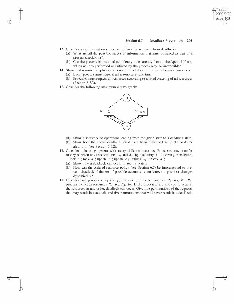
(Section 6.7.3).15. Consider the following maximum claims graph:
p1
R1
p2
R2
(a) Show a sequence of operations leading from the given state to a deadlock state.(b) Show how the above deadlock could have been prevented using the banker’s
algorithm (see Section 6.6.2).16. Consider a banking system with many different accounts. Processes may transfer
money between any two accounts, Ai and Aj , by executing the following transaction:lock Ai ; lock Aj ; update Ai ; update Aj ; unlock Ai ; unlock Aj ;
(a) Show how a deadlock can occur in such a system.(b) How can the ordered resource policy (see Section 6.7) be implemented to pre-
vent deadlock if the set of possible accounts is not known a priori or changesdynamically?
17. Consider two processes, p1 and p2. Process p1 needs resources R1, R2, R3, R4;process p2 needs resources R2, R3, R4, R5. If the processes are allowed to requestthe resources in any order, deadlock can occur. Give five permutations of the requeststhat may result in deadlock, and five permutations that will never result in a deadlock.