dear 1999-2004 sonata or 2001-2004 xg300 or xg350 owner
TRANSCRIPT
Dear 1999-2004 Sonata or 2001-2004 XG300 or XG350 Owner:
This notice is sent to you in accordance with the requirements of the National Traffic and Motor Vehicle Safety Act.
Hyundai has decided that a defect, which relates to motor vehicle safety, exists in certain model year 1999 through 2004 Hyundai Sonata vehicles produced beginning on September 15, 1998 through November 20, 2003 and certain model year 2001 through 2004 Hyundai XG300 and XG350 vehicles produced beginning on July 13, 2000 through November 20, 2003. This recall affects such vehicles registered in and operated in Connecticut, Delaware, Illinois, Indiana, Iowa, Maine, Maryland, Massachusetts, Michigan, Minnesota, Missouri, New Hampshire, New Jersey, New York, Ohio, Pennsylvania, Rhode Island, Vermont, West Virginia, and Wisconsin, and the District of Columbia (the Salt Belt).
Federal law requires that any vehicle lessor receiving this recall notice must forward a copy of this notice to the lessee within ten days.
What is the problem?"During winter months, large quantities of salt are used to de-ice roads in the Salt Belt states, noted above. Road salt may result in internal corrosion of the front subframe that is progressive and may result in thinning or perforation of the subframe steel. The corrosion is frequently vis-ible and often discovered during inspection or routine maintenance. You may also hear noises or notice tire misalignment and steering pull. These are indications your vehicle should be ser-viced. If these signals are undetected or unheeded, the corrosion may progress and the forward mounting of the lower control arm may detach from the sub-frame. If that happens, the vehicle may lose drive power to the wheels. In more severe circumstances, the front wheel may make contact with the fender or wheel well.
The corrosion provides warnings in the form of noises, tire misalignment and steering pull. If allowed to progress, separation of the forward mounting of the lower control arm may increase the risk of a vehicle crash.
What will Hyundai do?"We are asking you to schedule an appointment as soon as possible to take your vehicle to your Hyundai dealer. The Hyundai dealer will measure the thickness of the front subframe and inspect the front subframe for corrosion damage. If specified levels of corrosion damage are found, the front subframe will be replaced with a new subframe that incorporates additional holes in the upper and lower panels. If your front subframe does not require replacement, the dealer will add drainage holes to the subframe and will treat the subframe with rust-proofing material to arrest the corrosion process. This procedure will be performed at no charge to you. You should plan to leave your vehicle at your Hyundai dealer to have this service performed. Repair times will vary and depend on your dealer's appointment schedule.
Page 1 of 33
What should you do?"We urge you to call your Hyundai dealer to schedule an appointment to have this work per-formed as soon as possible.
What if you have other questions?"If you have any difficulty having this repair performed, we recommend that you call the Hyun-dai Customer Assistance Center at 1-800-633-5151. If you are still not satisfied that we have remedied this situation without charge, and within a reasonable amount of time, you may wish to write to the Administrator, National Highway Traffic Safety Administration, 1200 New Jer-sey Avenue, SE, Washington, D.C. 20590, or call their toll-free Vehicle Safety Hotline at 1-888-327-4236 (TTY: 1-800-424-9153), or go to http://www.safercar.gov.
Reimbursement Notification"Hyundai has a program for reimbursing owners of 1999 through 2004 Sonatas or 2001 through 2004 XG300 and XG350 vehicles produced through November 20, 2003 who paid to have the front subframe replaced after April 14, 2008 and prior to receiving this recall notification letter.
To obtain information about reimbursement from Hyundai, please call the Hyundai Customer Assistance Center at 1-800-633-5151. Ask about reimbursement information for campaign 089.
We urge your prompt attention to this important safety matter.
Hyundai Motor America
Page 2 of 33

July 10, 2009
TO:ALL HYUNDAI DEALER PRINCIPALS/GENERAL MANAGERS:ALL HYUNDAI DEALERSHIP SERVICE MANAGERS:ALL HYUNDAI DEALERSHIP PARTS MANAGERS:ALL HYUNDAI DEALERSHIP SALES MANAGERS:
SUBJECT: Recall Campaign 089 - Subframe Corrosion Inspection/ Replacement - TSB# 09-01-020
Hyundai Motor America is conducting a Customer Notification for inspection and rust-proofing treatment or replacement of vehicle's sub-frame on certain 1999-2004 model year Sonatas and 2001 - 2004 XG300/XG350 vehicles. This campaign provides a procedure for the inspection and rust-proofing treatment or replace-ment of the Subframe.
In order to identify only those vehicles affected by Campaign 089, it will be necessary to access Hyundai Motor America's "Warranty Vehicle Information" screen via WEBDCS before starting the repair. The "Warranty Vehicle Information" screen will identify affected vehicles with an open Campaign 089.
Dealer Letter, Customer Letter, and Technical Service Bulletin #9-01-020 will be posted on Hyundai's Website July 10, 2009.
All Hyundai dealers will be shipped a supply of the following materials in their weekly parts shipments:
1.Tool kit(s)2.Chemical kit - additional chemicals can be ordered from your facing PDC as more chemicals are required.
Customer notification letters will be mailed in weekly flights starting Friday, July 17, 2009. It is IMPORTANT TO SUBMIT A CAMPAIGN CLAIM FOR EACH VEHICLE SERVICED so your dealership can be compensated for your work and Hyundai can maintain accurate records of campaign completions.
LEGAL LIABILITY NOTICE: You are required to keep confidential any and all information and documents provided to you by Hyundai Motor America in the conduct of carrying out work for this recall campaign. Hyundai Motor America dealers may use owner information provided for the campaign only for the purpose of conducting and performing this recall campaign, and for no other purpose.
Page 3 of 33
Hyundai appreciates your cooperation and support. Questions may be directed to your District Parts and Service Manager or Warranty HELPREP line at 1-877-446-2922.
HYUNDAI MOTOR AMERICA
Page 4 of 33
Technical Service Bulletin
Sub
Group
CIRCULATE TO: [ ] GENERAL MANAGER
[X] SERVICE MANAGER[X] SERVICE ADVISOR [X] WARRANTY
[X] PARTS MAN
CAMPAIGN
Number09-01-020-2
DateSEPTEMBER, 2009
ModelSONATA / XG300 / XG350
jectEF SONATA, XG300, XG350 - FRONT SUBFRAME
CORROSION TREATMENT (CAMPAIGN 089)
MGR [ ] SALES MANAGER
AGER [X] TECHNICIAN
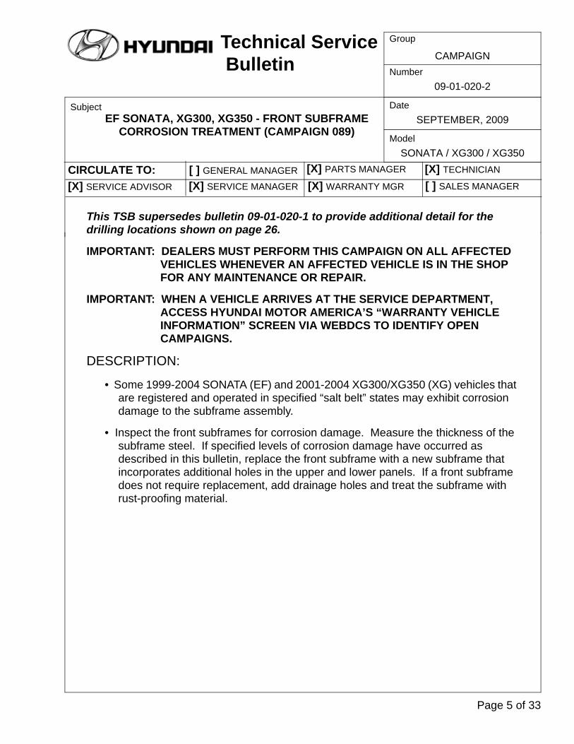
This TSB supersedes bulletin 09-01-020-1 to provide additional detail for the drilling locations shown on page 26.
IMPORTANT: DEALERS MUST PERFORM THIS CAMPAIGN ON ALL AFFECTED VEHICLES WHENEVER AN AFFECTED VEHICLE IS IN THE SHOP FOR ANY MAINTENANCE OR REPAIR.
IMPORTANT: WHEN A VEHICLE ARRIVES AT THE SERVICE DEPARTMENT, ACCESS HYUNDAI MOTOR AMERICA’S “WARRANTY VEHICLE INFORMATION” SCREEN VIA WEBDCS TO IDENTIFY OPEN CAMPAIGNS.
DESCRIPTION:
• Some 1999-2004 SONATA (EF) and 2001-2004 XG300/XG350 (XG) vehicles that are registered and operated in specified “salt belt” states may exhibit corrosion damage to the subframe assembly.
• Inspect the front subframes for corrosion damage. Measure the thickness of the subframe steel. If specified levels of corrosion damage have occurred as described in this bulletin, replace the front subframe with a new subframe that incorporates additional holes in the upper and lower panels. If a front subframe does not require replacement, add drainage holes and treat the subframe with rust-proofing material.
Page 5 of 33

SUMMARY OF SERVICE PROCEDURE:
APPLICABLE VEHICLES - VERIFY THAT THE VEHICLE IS IDENTIFIED AS AFFECTED BY THE CAMPAIGN VIA WEBDCS.
• Model : SONATA (EF), XG300 and XG350 (XG)
• Applicable vehicle production date range : From Job#1 through November 20, 2003
• Area : Salt belt states as follows:
Connecticut, Delaware, Illinois, Indiana, Iowa, Maine, Maryland, Massachusetts, Michigan, Minnesota, Missouri, New Hampshire, New Jersey, New York, Ohio, Pennsylvania, Rhode Island, Vermont, West Virginia, Wisconsin, and the District of Columbia.
Page 6 of 33

Technical Service Bulletin
Group
Number09-01-020-2
CAMPAIGN
PARTS REQUIRED:
CAUTION: * There exists two versions of the Front Roll Stopper Bracket Assembly campaign parts (21910-38100QQH, 21910-38600QQH, and 21910-38650QQH). The previous version of the roll stopper has hole centers that are horizontally aligned. The new version has hole centers that are not horizontally aligned.
CAUTION: Ensure that the correct (new) Front Roll Stopper Bracket Assembly is being used when replacing a subframe under the campaign.
SUBFRAME ASSEMBLY REPLACEMENTModel Kit # Components Remark
EF
62405-38300QQH
Subframe, 4 spring washers, 2 spring washers, 3 bolts, 1 bolt, 2 studs, 2 stud nuts
21910-38100QQH*
Front roll mount, I4/V6 M/T
Only required for vehicles pro-duced from Job#1 through Apr. 13, 1999
21910-38600QQH*
Front roll mount, V6 A/T
21910-38650QQH*
Front roll mount, I4 A/T
XG 62405-39003QQH
Subframe, 4 spring washers, 2 spring washers, 3 bolts, 1 bolt, 2 studs, 2 stud nuts
EF/XG54569-38000QQH
Bolt M14 x 86; 2 EAWasher 2.5T 4 EA.
For subframes replaced on vehicles built from Job#1 through Aug.13, 2000
FRONT ROLL STOPPER BRACKET IDENTIFICATION
Previous part: Hole centers align in a straight horizontal line.
This part is NOT compatible with the sub-frame assembly 62405-38300QQH.
New part: Hole centers do not align in a straight horizontal line.
This part IS compatible with the sub-frame assembly 62405-38300QQH.
Page 7 of 33
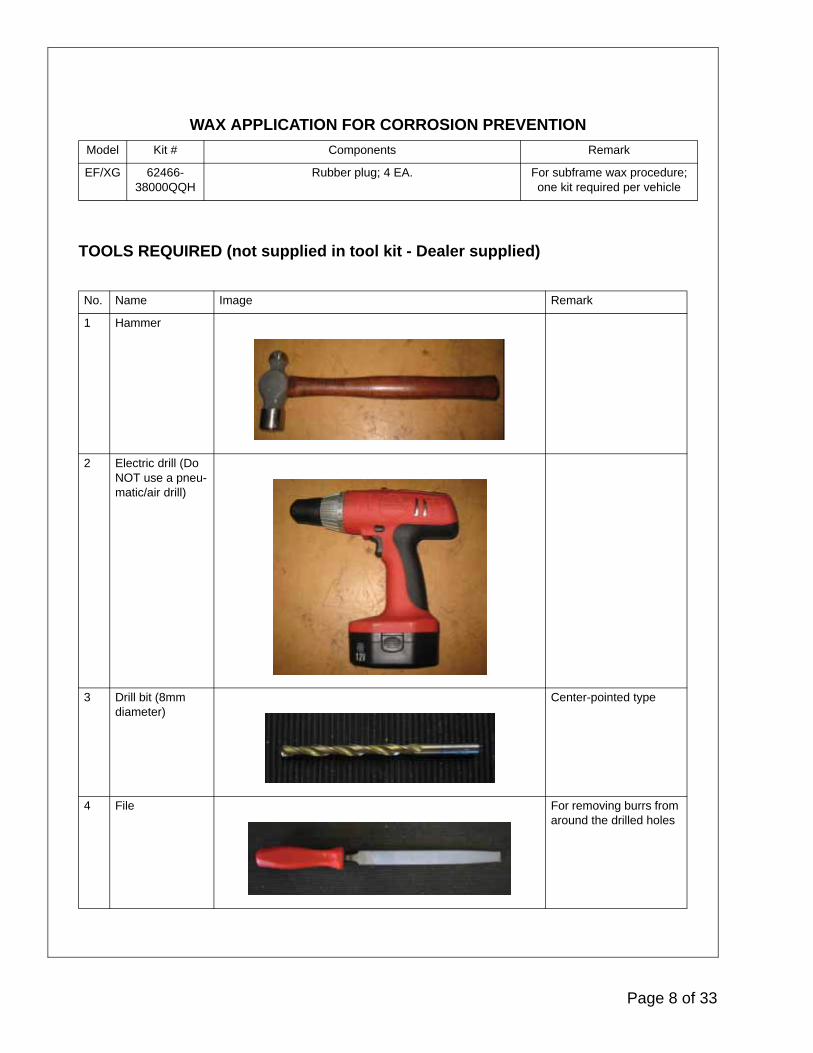
TOOLS REQUIRED (not supplied in tool kit - Dealer supplied)
WAX APPLICATION FOR CORROSION PREVENTIONModel Kit # Components Remark
EF/XG 62466-38000QQH
Rubber plug; 4 EA. For subframe wax procedure; one kit required per vehicle
No. Name Image Remark
1 Hammer
2 Electric drill (Do NOT use a pneu-matic/air drill)
3 Drill bit (8mm diameter)
Center-pointed type
4 File For removing burrs from around the drilled holes
Page 8 of 33
Technical Service Bulletin
Group
Number09-01-020-2
CAMPAIGN
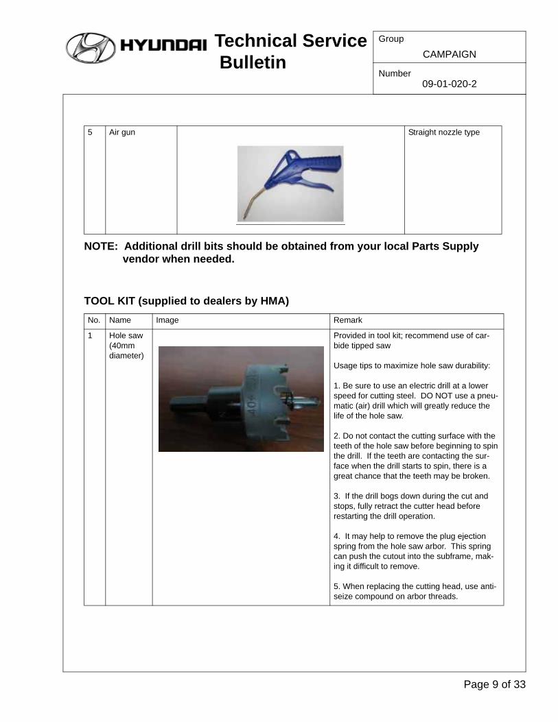
NOTE: Additional drill bits should be obtained from your local Parts Supply vendor when needed.
TOOL KIT (supplied to dealers by HMA)
5 Air gun Straight nozzle type
No. Name Image Remark
1 Hole saw (40mm diameter)
Provided in tool kit; recommend use of car-bide tipped saw
Usage tips to maximize hole saw durability:
1. Be sure to use an electric drill at a lower speed for cutting steel. DO NOT use a pneu-matic (air) drill which will greatly reduce the life of the hole saw.
2. Do not contact the cutting surface with the teeth of the hole saw before beginning to spin the drill. If the teeth are contacting the sur-face when the drill starts to spin, there is a great chance that the teeth may be broken.
3. If the drill bogs down during the cut and stops, fully retract the cutter head before restarting the drill operation.
4. It may help to remove the plug ejection spring from the hole saw arbor. This spring can push the cutout into the subframe, mak-ing it difficult to remove.
5. When replacing the cutting head, use anti-seize compound on arbor threads.
Page 9 of 33
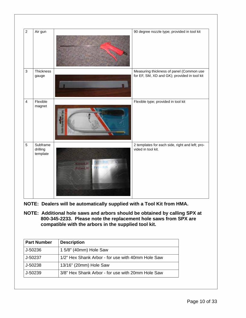
NOTE: Dealers will be automatically supplied with a Tool Kit from HMA.
NOTE: Additional hole saws and arbors should be obtained by calling SPX at 800-345-2233. Please note the replacement hole saws from SPX are compatible with the arbors in the supplied tool kit.
2 Air gun 90 degree nozzle type; provided in tool kit
3 Thickness gauge
Measuring thickness of panel (Common use for EF, SM, XD and GK); provided in tool kit
4 Flexible magnet
Flexible type; provided in tool kit
5 Subframe drilling template
2 templates for each side, right and left; pro-vided in tool kit.
Part Number DescriptionJ-50236 1 5/8” (40mm) Hole Saw
J-50237 1/2” Hex Shank Arbor - for use with 40mm Hole Saw
J-50238 13/16” (20mm) Hole Saw
J-50239 3/8” Hex Shank Arbor - for use with 20mm Hole Saw
Page 10 of 33
Technical Service Bulletin
Group
Number09-01-020-2
CAMPAIGN
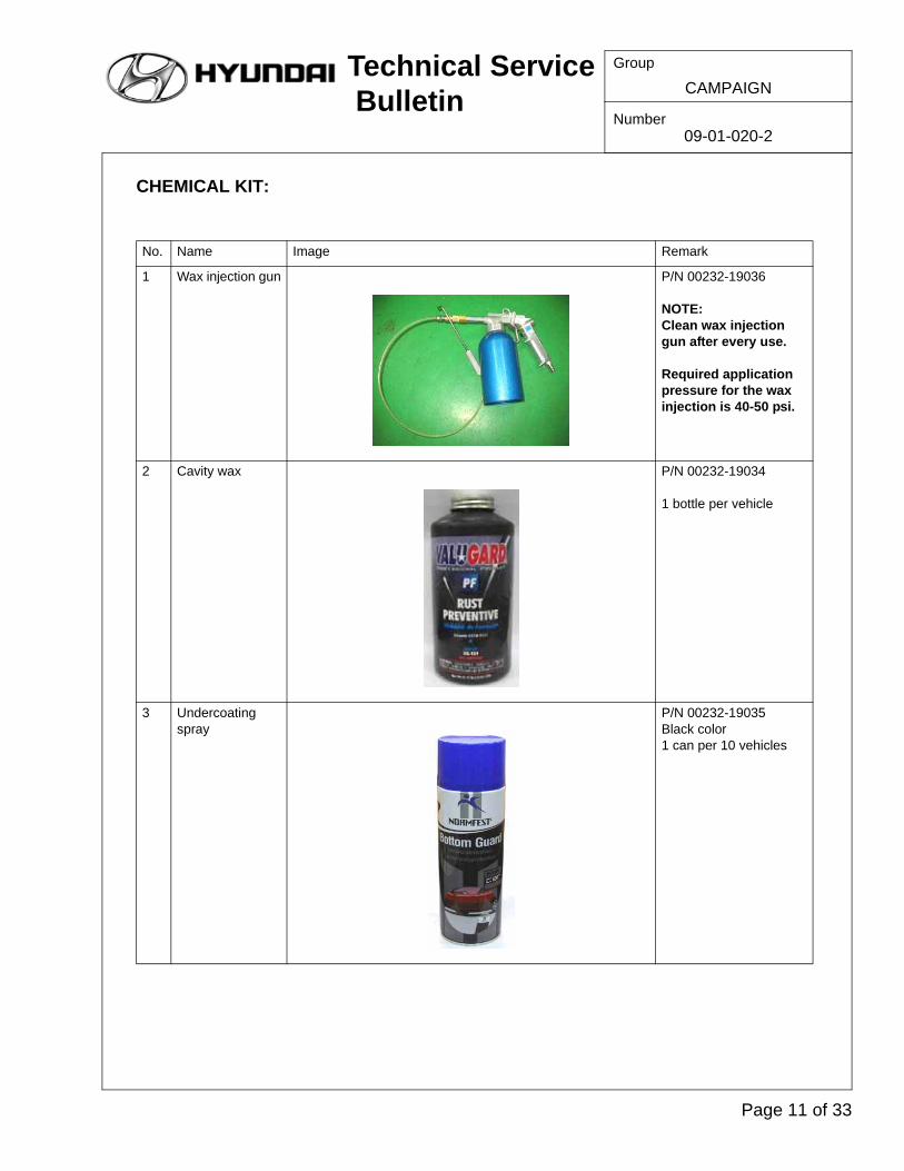
CHEMICAL KIT:
No. Name Image Remark
1 Wax injection gun P/N 00232-19036
NOTE: Clean wax injection gun after every use.
Required application pressure for the wax injection is 40-50 psi.
2 Cavity wax P/N 00232-19034
1 bottle per vehicle
3 Undercoating spray
P/N 00232-19035Black color1 can per 10 vehicles
Page 11 of 33

NOTE: Dealers will be supplied with an initial order of the Chemical Kit. Additional product should be ordered through your facing PDC.
SERVICE PROCEDURE:
• SUBFRAME INSPECTION
1. Lift up vehicle
2. Lightly strike the subframe throughout with a hammer.
CAUTION: Be careful DO NOT strike the subframe too hard to prevent deformation damage.
Page 12 of 33
Technical Service Bulletin
Group
Number09-01-020-2
CAMPAIGN
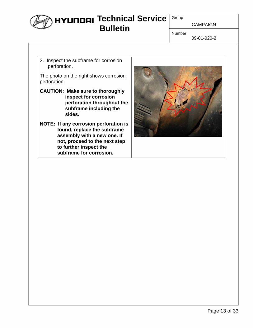
3. Inspect the subframe for corrosion perforation.
The photo on the right shows corrosion perforation.
CAUTION: Make sure to thoroughly inspect for corrosion perforation throughout the subframe including the sides.
NOTE: If any corrosion perforation is found, replace the subframe assembly with a new one. If not, proceed to the next step to further inspect the subframe for corrosion.
Page 13 of 33
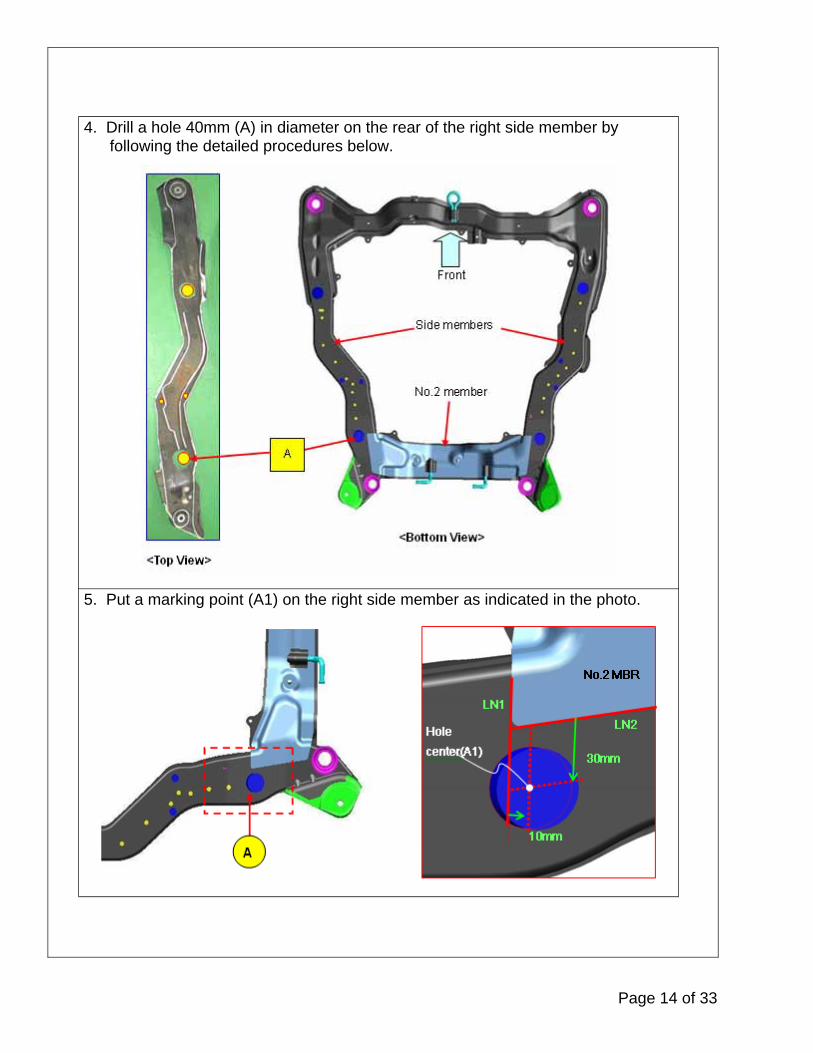
4. Drill a hole 40mm (A) in diameter on the rear of the right side member by following the detailed procedures below.
5. Put a marking point (A1) on the right side member as indicated in the photo.
Page 14 of 33
Technical Service Bulletin
Group
Number09-01-020-2
CAMPAIGN
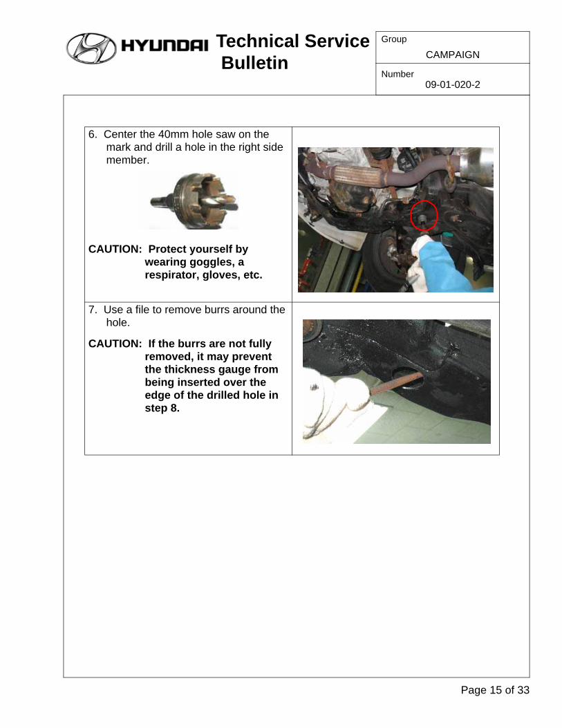
6. Center the 40mm hole saw on the mark and drill a hole in the right side member.
CAUTION: Protect yourself by wearing goggles, a respirator, gloves, etc.
7. Use a file to remove burrs around the hole.
CAUTION: If the burrs are not fully removed, it may prevent the thickness gauge from being inserted over the edge of the drilled hole in step 8.
Page 15 of 33

8. Insert the 1.5mm groove of the thickness gauge through the hole. Check the thickness of the subframe at as many points around the hole as possible.
9. If the subframe metal fits into the 1.5mm groove of the thickness gauge, replace the subframe assembly. Reference the SUBFRAME ASSEMBLY REPLACEMENT chart on page 7. If the subframe metal does not fit into the thickness gauge, continue to the next step.
2.5mm 1.5mm
Page 16 of 33

Technical Service Bulletin
Group
Number09-01-020-2
CAMPAIGN
10. Drill a hole 40mm (C) in diameter on the rear of the left side member and check the thickness of the subframe metal of the left side member, as before.
Page 17 of 33

SUBFRAME REPLACEMENT PROCEDURE: This instruction provides a procedure to replace the SONATA (EF) subframe more easily and efficiently than the original procedure.
11. If the subframe metal fits into the 1.5mm groove of the thickness gauge, replace the subframe assembly. Reference the SUBFRAME ASSEMBLY REPLACEMENT chart on page 7. If the subframe metal does not fit into the thickness gauge, continue to the WAX APPLICATION FOR CORROSION PREVENTION procedure on page 24.
Original Procedure Revised Procedure
To replace the subframe (A), remove it simultaneously with the steering gearbox
(B).
It is possible to remove the subframe (A) without detaching the steering gearbox (B) from the vehicle. DO NOT remove the steering gearbox for the subframe
replacement.
Page 18 of 33

Technical Service Bulletin
Group
Number09-01-020-2
CAMPAIGN
1. Raise the hood.
2. Remove the battery (D).
3. Remove the air cleaner (C).
4. Remove the 2 main wiring harness mounting nuts (E) then slacken the wiring harness.
5. Remove the 3 rear roll stopper mounting bolts (F).
Page 19 of 33

6. Photo of the location where the rear roll stopper mounting bolts had been installed (G).
7. Lift the vehicle off the ground.
8. Remove the 2 right under covers (I).
9. Remove the front exhaust pipe (J).
Page 20 of 33
Technical Service Bulletin
Group
Number09-01-020-2
CAMPAIGN
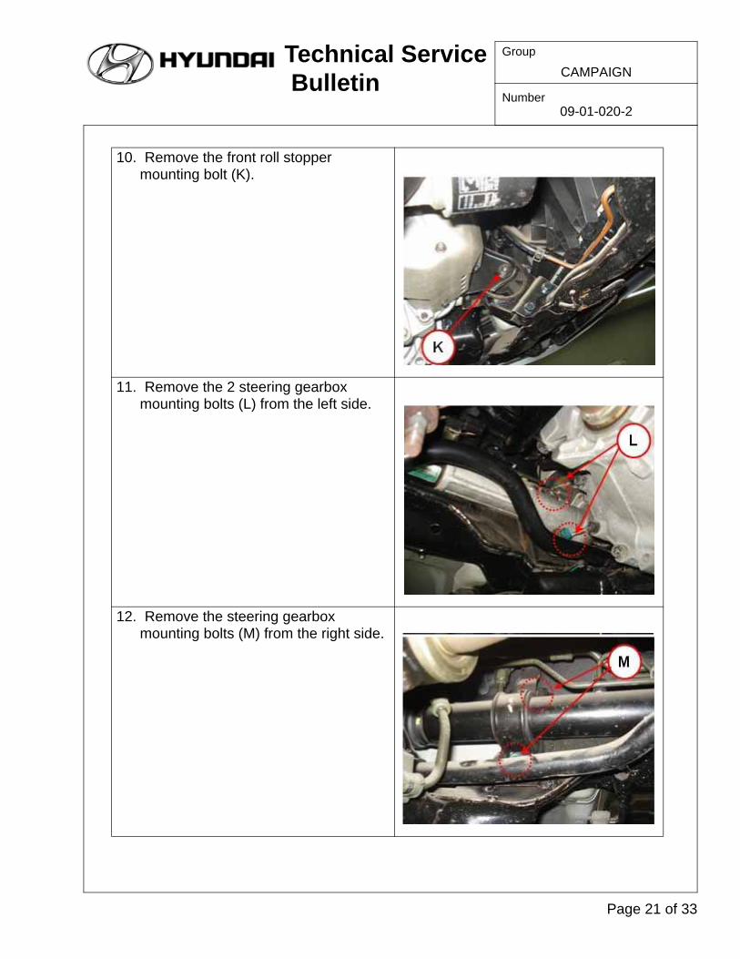
10. Remove the front roll stopper mounting bolt (K).
11. Remove the 2 steering gearbox mounting bolts (L) from the left side.
12. Remove the steering gearbox mounting bolts (M) from the right side.
Page 21 of 33
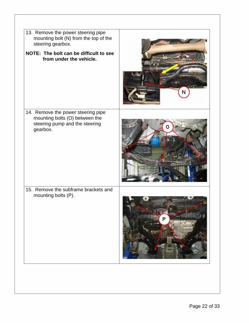
13. Remove the power steering pipe mounting bolt (N) from the top of the steering gearbox.
NOTE: The bolt can be difficult to see from under the vehicle.
14. Remove the power steering pipe mounting bolts (O) between the steering pump and the steering gearbox.
15. Remove the subframe brackets and mounting bolts (P).
Page 22 of 33

Technical Service Bulletin
Group
Number09-01-020-2
CAMPAIGN
16. Support the subframe with a jack (Q).
17. Remove the ball joint mounting bolt (R).
18. Remove the bolts (S) from the lower end of the strut assembly.
19. Repeat steps 17 and 18 on the other side.
20. Remove the subframe center mounting nut (T).
Page 23 of 33
WAX APPLICATION FOR CORROSION PREVENTION
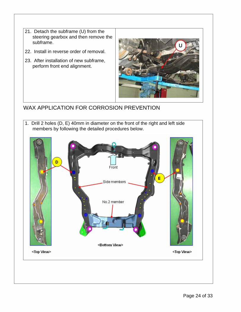
21. Detach the subframe (U) from the steering gearbox and then remove the subframe.
22. Install in reverse order of removal.
23. After installation of new subframe, perform front end alignment.
1. Drill 2 holes (D, E) 40mm in diameter on the front of the right and left side members by following the detailed procedures below.
Page 24 of 33
Technical Service Bulletin
Group
Number09-01-020-2
CAMPAIGN
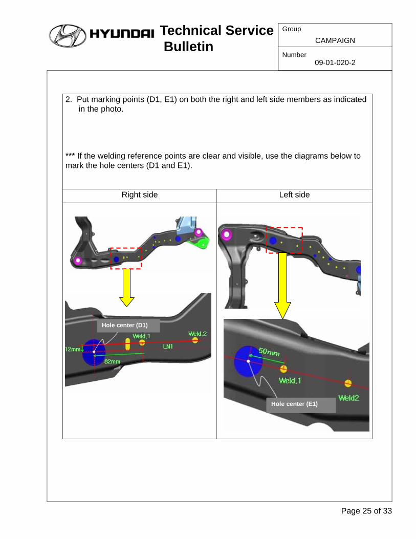
2. Put marking points (D1, E1) on both the right and left side members as indicated in the photo.
*** If the welding reference points are clear and visible, use the diagrams below to mark the hole centers (D1 and E1).
Right side Left side
Hole center (D1)
Hole center (E1)
Page 25 of 33

*** If the welding reference points are unclear and not visible, use the diagrams below to mark the hole centers (D1 and E1).
Right side Left side
3. Center the 40mm hole saw on the mark and drill a hole in the right side member. Repeat this procedure for the left.
CAUTION: Protect yourself by wearing goggles, a respirator, gloves, etc.
Hole center (D1)
Hole center (E1)
Page 26 of 33

Technical Service Bulletin
Group
Number09-01-020-2
CAMPAIGN
4. Drill four holes 8mm in diameter on the middle of the right and left side members by following the detailed procedures below.
5. Align the hole jig with the right side member as shown in the photo at the right. Put two marks on the right side member. And repeat this procedure for the left.
Page 27 of 33

Details of locations
6. Center the 8mm drill bit on the marks and drill two holes in the right side member according to the template. Repeat this procedure for the left.
Page 28 of 33

Technical Service Bulletin
Group
Number09-01-020-2
CAMPAIGN
7. Remove fragments of rust from the inside of the subframe by following the detailed procedures below.
8. Strike the subframe throughout with a hammer.
CAUTION: Do NOT strike in the area of the four holes (F, G) 40 mm in diameter to avoid causing deformation damage.
9. Insert a flexible magnet through the 40mm holes and remove any fragments of rust from inside the subframe.
Page 29 of 33
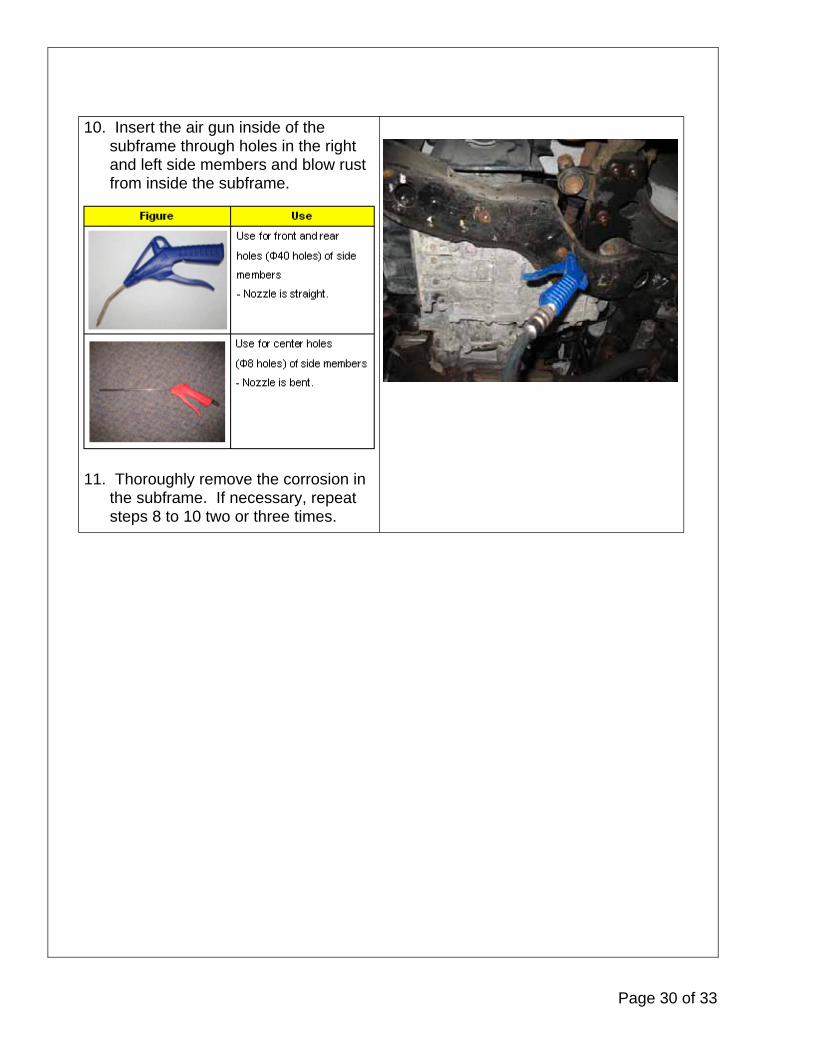
10. Insert the air gun inside of the subframe through holes in the right and left side members and blow rust from inside the subframe.
11. Thoroughly remove the corrosion in the subframe. If necessary, repeat steps 8 to 10 two or three times.
Page 30 of 33
Technical Service Bulletin
Group
Number09-01-020-2
CAMPAIGN
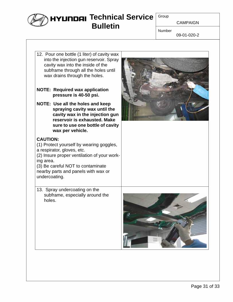
12. Pour one bottle (1 liter) of cavity wax into the injection gun reservoir. Spray cavity wax into the inside of the subframe through all the holes until wax drains through the holes.
NOTE: Required wax application pressure is 40-50 psi.
NOTE: Use all the holes and keep spraying cavity wax until the cavity wax in the injection gun reservoir is exhausted. Make sure to use one bottle of cavity wax per vehicle.
CAUTION: (1) Protect yourself by wearing goggles, a respirator, gloves, etc. (2) Insure proper ventilation of your work-ing area.(3) Be careful NOT to contaminate nearby parts and panels with wax or undercoating.
13. Spray undercoating on the subframe, especially around the holes.
Page 31 of 33
WARRANTY CLAIM INFORMATION:
IMPORTANT: If a subframe is replaced, a front end alignment MUST be performed and is included in the campaign labor operation time.
NOTE: Submit claim using the Campaign Entry Screen
NOTE: * Each applicable claim includes a sublet amount for chemical, hole saw, and drill bit reimbursement.
NOTE: * Reimbursement for the Cavity Wax Injection Gun will be processed in Dealership’s Parts statement.
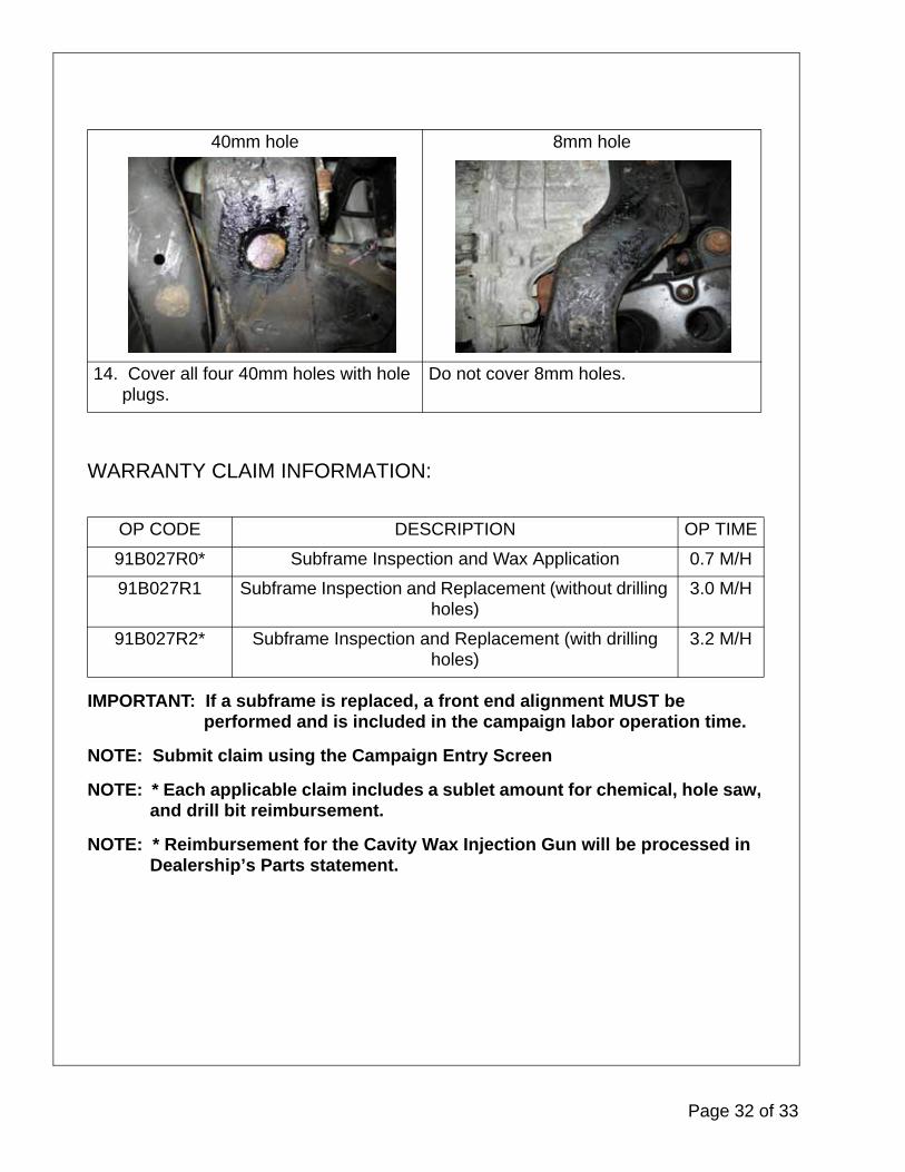
40mm hole 8mm hole
14. Cover all four 40mm holes with hole plugs.
Do not cover 8mm holes.
OP CODE DESCRIPTION OP TIME
91B027R0* Subframe Inspection and Wax Application 0.7 M/H
91B027R1 Subframe Inspection and Replacement (without drilling holes)
3.0 M/H
91B027R2* Subframe Inspection and Replacement (with drilling holes)
3.2 M/H
Page 32 of 33

Technical Service Bulletin
Group
Number09-01-020-2
CAMPAIGN
PARTS SCRAP INFORMATION:
1. Subframe Inspection and Replacement (without drilling holes) - It is required that digital photos be taken of the replaced parts as well as the VIN plate. These pictures must be attached to their respective repair order for DPSM review. The removed subframe may be scrapped.
2. Subframe Inspection and Replacement (with drilling holes) - It is required to retain the core sample and repair information for DPSM review. The removed subframe may be scrapped.
3. Subframe Inspection and Wax Application - It is required to retain the core sample and repair information for DPSM review.
Page 33 of 33