decade plus dental chair - dental supplies | a-decus.a-dec.com/en/~/media/adec/document...
TRANSCRIPT

InstructIons for use
Decade® Plus Dental ChairModel 1221

Copyright
© 2012 A-dec Inc. All rights reserved.
A-dec Inc. makes no warranty of any kind with regard to this material, including, but not limited to, the implied warranties of merchantability and fitness for a particular purpose. A-dec Inc. shall not be held liable for any errors contained herein or any consequential or other damages concerning the furnishing, performance or use of this material. The informa-tion in this document is subject to change without notice. If you find any problems in the documentation, please report them to us in writing. A-dec Inc. does not warrant that this document is error-free.
No part of this document may be copied, reproduced, altered, or transmitted in any form or by any means, electronic or mechanical, including photocopying, recording, or by any information storage and retrieval system, without prior written permission from A-dec Inc.
Trademarks and Additional Intellectual Property Rights
A-dec, the A-dec logo, A-dec 500, A-dec 300, Cascade, Cascade Master Series, Century Plus, Continental, Decade, ICX, ICV, Performer, Preference, Preference Collection, Preference ICC, and Radius are registered in the United States and other countries. A-dec 200, Preference Slimline, and reliablecreativesolutions are also trademarks of A-dec Inc. None of the trademarks or trade names in this document may be reproduced, copied, or manipulated in any manner without the express, written approval of the trademark owner.
Certain touchpad symbols are proprietary to A-dec Inc. Any use of these symbols, in whole or in part, without the express written consent of A-dec Inc., is strictly prohibited.
Regulatory Information
The Regulatory Information and Specifications document is delivered with A-dec dental device equipment as mandated by agency requirements. If you need this information, please go to the Document Library at www.a-dec.com.
Product Service
For service information, contact your local authorized A-dec dealer. To find your local dealer, go to www.a-dec.com.
IFUbk8
86062000_2012_10_RevB.book Page 0 Monday, November 5, 2012 2:23 PM

C O N T E N T S
86062000_2012_10_RevB.book Page i Monday, November 5, 2012 2:23 PM
1 INTRODUCTION .............................................................................. 1About the A-dec Decade Plus Dental Chair .............................................................................1
2 FEATURES AND OPERATION............................................................... 2About Your Decade Plus Dental Chair .........................................................................................2Operate Dental Chair .......................................................................................................................3
Dental Chair Stop Plate ...............................................................................................................3Dental Chair LED .........................................................................................................................3
Operate Footswitch ..........................................................................................................................4Direction Arrows..........................................................................................................................4Program Buttons...........................................................................................................................5
Factory Presets .........................................................................................................................5Customize Dental Chair Positions ........................................................................................5Customize Dental Chair Position 3 ......................................................................................5
Folding Armrest................................................................................................................................6Swivel Brake ......................................................................................................................................7Double-Articulating Headrest ........................................................................................................8
Headrest Positioning ...................................................................................................................8Headrest Positioning for Wheelchair ........................................................................................9
Upholstery .......................................................................................................................................10Replace Backrest Upholstery ....................................................................................................10Replace Seat Upholstery............................................................................................................11Replace Armrest Upholstery ....................................................................................................12
Remove the Armrest Upholstery ........................................................................................12Replace the Armrest Upholstery ........................................................................................12
Replace Double-Articulating Headrest Upholstery ..............................................................13
3 ADJUSTMENTS ..............................................................................14Swivel Brake Adjustment ..............................................................................................................14Headrest Drift Adjustment ...........................................................................................................15
4 MAINTENANCE ..............................................................................16Touch and Transfer Surfaces ........................................................................................................16Waterline Treatment ......................................................................................................................16
5 APPENDIX: WARRANTY AND SPECIFICATIONS.........................................17Warranty ..........................................................................................................................................17Specifications...................................................................................................................................17
Chair Capacity ............................................................................................................................17Other Specifications ...................................................................................................................18
86.0620.00 Rev B i

Decade Plus Dental Chair Model 1221 Instructions for Use
86062000_2012_10_RevB.book Page ii Monday, November 5, 2012 2:23 PM
ii 86.0620.00 Rev B
86.0620.00 Rev B 1
1
INTRODUCTION
This guide contains information on the Decade Plus Dental Chair, including:
• Features and operation
• Adjustments
• Maintenance
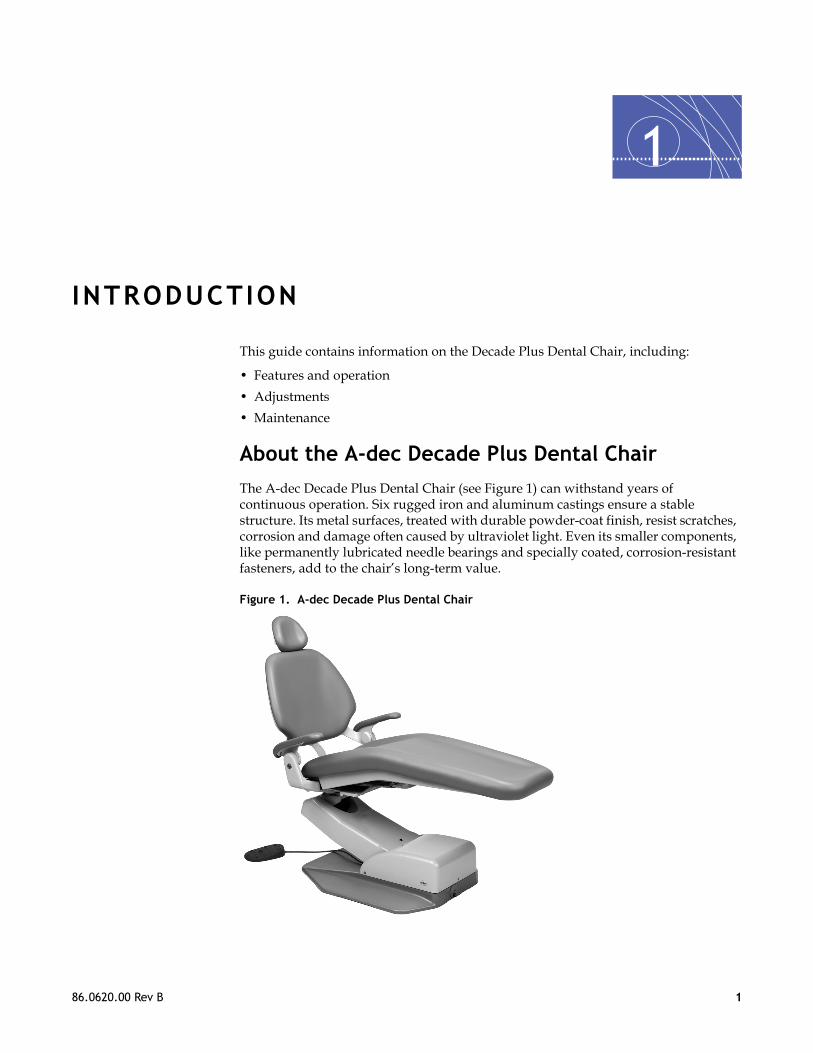
About the A-dec Decade Plus Dental Chair
The A-dec Decade Plus Dental Chair (see Figure 1) can withstand years of continuous operation. Six rugged iron and aluminum castings ensure a stable structure. Its metal surfaces, treated with durable powder-coat finish, resist scratches, corrosion and damage often caused by ultraviolet light. Even its smaller components, like permanently lubricated needle bearings and specially coated, corrosion-resistant fasteners, add to the chair’s long-term value.
Figure 1. A-dec Decade Plus Dental Chair
86062000_2012_10_RevB.book Page 1 Monday, November 5, 2012 2:23 PM

2
86062000_2012_10_RevB.book Page 2 Monday, November 5, 2012 2:23 PM
FEATURES AND OPERATION
This section describes the features and operation of the A-dec Decade Plus Dental Chair.
About Your Decade Plus Dental ChairYour A-dec Decade Plus Dental Chair is an electronically controlled, hydraulically powered dental chair (see Figure 2).
Figure 2. A-dec Decade Plus Dental Chair
(A) Double-Articulating Headrest; (B) Swivel Brake; (C) 8-Button Footswitch (Optional); (D) Folding Armrest
A
C
B
D
2 86.0620.00 Rev B

Decade Plus Dental Chair Model 1221 Instructions for Use
86062000_2012_10_RevB.book Page 3 Monday, November 5, 2012 2:23 PM
Operate Dental ChairThe optional 8-button footswitch controls the A-dec Decade Plus Dental Chair. The chair also can be controlled by a touchpad if a delivery system is installed. You can position the chair to suit your requirements by moving the chair back up or down and moving the chair base up and down (see Figure 3).
Dental Chair Stop Plate
Pressing the chair stop plate (see Figure 3) stops the chair movement immediately. Should anything inadvertently become lodged under the chair, press Base Up on the footswitch to raise the chair to remove the object. As long as you apply pressure to the stop plate, the chair does not move down.
Dental Chair LED
The chair LED lights when the chair power is on (see Figure 3).
Figure 3. Lift, Tilt and Stop Plate
(A) Chair Back Up/Down Tilt; (B) Chair Stop Plate; (C) Base Up/Down Lift; (D) Chair LED
A
B
C
D
86.0620.00 Rev B 3

FEATURES AND OPERATION
86062000_2012_10_RevB.book Page 4 Monday, November 5, 2012 2:23 PM
Operate FootswitchThe optional 8-button footswitch allows you to control the Decade Plus Dental Chair. You can use the direction arrows to manually move the chair base and back or the numbered position buttons to automatically move the chair to a programmed position (see Figure 4).
Figure 4. Footswitch
(A) Chair Position Button; (B) Chair Program Button; (C) Chair Direction Arrow
Direction Arrows
The chair direction arrows on the footswitch allow you to manually move the chair base up/down and back up/down. Table 1 lists and describes the direction arrows.
Table 1. Chair Direction
Footswitch Icon Action
Back down
Base down
Back up
Base up
1 2
30
A
C
A
C
B
4 86.0620.00 Rev B

Decade Plus Dental Chair Model 1221 Instructions for Use
86062000_2012_10_RevB.book Page 5 Monday, November 5, 2012 2:23 PM
Program Buttons
The program button saves the settings for entry/exit 0, Positions 1 and 2 and x-ray/rinse Position 3 (see Figure 4 on page 4).
Factory Presets
Chair position buttons are factory preset. Table 2 lists and defines the footswitch factory presets.
Table 2. Footswitch Factory Presets
Customize Dental Chair Positions
To customize the chair positions:
1. Use the manual controls to adjust the chair position as desired.2. Press and release the Program button. One beep indicates
programming mode.3. Within four seconds, press the chair position button you wish to reset (for example,
Position 1). Three beeps indicates the new setting is programmed in memory.
Customize Dental Chair Position 3
A-dec sets Position 3 in the factory as the x-ray/rinse position. In this mode, the chair back rises to a factory-programmed upright position that gives the patient access to the cuspidor. Pressing Position 3 a second time lowers the chair back to its previous operating position.
You can set Position 3 either as a third customized position or to function as an “undo” button that reverses the last positioning, returning the chair to its previous position. To do this, contact an authorized A-dec Dealer.
NOTE To stop the chair at any point, push any chair button on the footswitch or touchpad.
NOTE Please follow standard patient care precautions when using the chair preset position functions.
Footswitch Icon Preset Definition
Entry/Exit. Automatically positions the chair base and back to the entry/exit position.
Position 1. Automatically positions the chair base and back to position 1.
Position 2. Automatically positions the chair base and back to position 2.
Position 3 (x-ray/rinse). Toggles between rinse position and the previous operating position.
86.0620.00 Rev B 5

FEATURES AND OPERATION
86062000_2012_10_RevB.book Page 6 Monday, November 5, 2012 2:23 PM
Folding ArmrestThe armrests fold down and out of the way for patient entry and exit. When lifted, the armrests lock securely in place for patient comfort during procedures. To position:
• Lower the armrest by pressing the button on the side of the arm (see Figure 5.).
• Lock the armrest by lifting it until it locks in place.
Figure 5. Folding Armrest
(A) Armrest Release Button
A
6 86.0620.00 Rev B

Decade Plus Dental Chair Model 1221 Instructions for Use
86062000_2012_10_RevB.book Page 7 Monday, November 5, 2012 2:23 PM
Swivel BrakeWhen engaged, the chair swivel brake restricts rotation of the chair. With the brake released, you can rotate the chair to any position within about 30° either side of center. To use:
• Push the brake lever to the right to release the swivel brake (see Figure 6).
• Push the brake lever to the left to engage the swivel brake.
Figure 6. Swivel Brake
(A) Swivel Brake Lever; (B) Release Brake; (C) Engage Brake
A
C
B
86.0620.00 Rev B 7

FEATURES AND OPERATION
86062000_2012_10_RevB.book Page 8 Monday, November 5, 2012 2:23 PM
Double-Articulating HeadrestThe double-articulating headrest offers the widest range of headrest positions possible. A convenient locking knob allows you to easily accommodate most patients and procedures.
Headrest Positioning
To position the headrest:
1. Release the locking knob by turning the knob out (left), and then adjust the headrest as necessary to fit the head and neck (see Figure 7).
2. Lock the headrest in the desired position by turning the knob in (right).3. To move the headrest higher or lower, pull up or push down on the headrest until it is at
the desired height.
Figure 7. Double-Articulating Headrest
(A) Locking Knob
A
8 86.0620.00 Rev B

Decade Plus Dental Chair Model 1221 Instructions for Use
86062000_2012_10_RevB.book Page 9 Monday, November 5, 2012 2:23 PM
Headrest Positioning for Wheelchair
To position the headrest to accommodate wheelchair patients:
1. Slide the headrest up until it is free from the chair, turn the headrest 180°, slide it back into the backrest, and push it all the way down.
2. Run the chair to its full back up position. 3. Adjust headrest height by moving the dental chair up or down (using the base up
function on the footswitch), and position the headrest as desired (see Figure 8).
Figure 8. Positioning for Wheelchair Usage
86.0620.00 Rev B 9

FEATURES AND OPERATION
86062000_2012_10_RevB.book Page 10 Monday, November 5, 2012 2:23 PM
UpholsteryThe upholstery on your chair is installed in four sections: back, seat, headrest and armrests. Each section is easily removed and replaced.
Replace Backrest Upholstery
To remove and replace the backrest upholstery:
1. Remove the four screws securing the backrest cover and set the cover and screws aside (see Figure 9).
2. Using a 5/64" hex key, remove the four mounting screws that hold the upholstery to the backrest, then remove the existing upholstery.
3. Reverse this procedure to replace the upholstery.
Figure 9. Replace Backrest Upholstery
(A) Back Frame; (B) Backrest Upholstery
A
B
10 86.0620.00 Rev B

Decade Plus Dental Chair Model 1221 Instructions for Use
86062000_2012_10_RevB.book Page 11 Monday, November 5, 2012 2:23 PM
Replace Seat Upholstery
To remove and replace the seat upholstery:
1. Raise the chair back and disconnect the chair from the power source.
2. Remove the chair swivel brake cover. 3. Remove the existing seat upholstery.4. Align the new upholstery to the holes in the chair casting (see Figure 10).5. Insert the pins through the upholstery and chair casting (see Figure 10).6. Reinstall the chair swivel brake cover.7. Plug in chair.
Figure 10. Replace Seat Upholstery
(A) Swivel Brake Cover; (B) Upholstery Pin (on the Right Side); (C) Chair Casting; (D) Seat Upholstery
WARNING Be sure you disconnect the power source to prevent injury caused by accidental lowering of the chair.
A
BD
C
86.0620.00 Rev B 11

FEATURES AND OPERATION
86062000_2012_10_RevB.book Page 12 Monday, November 5, 2012 2:23 PM
Replace Armrest Upholstery
Remove the Armrest Upholstery
1. Loosen the rear-most mounting screw a half turn with the 1/8” hex key (see Figure 11). 2. Remove the front and middle mounting screws from the underside of each armrest. 3. Remove the armrest upholstery by sliding it off the armrest.
Figure 11 Remove Armrest Upholstery
(A) Mounting Screws; B) Rear-most Mounting Screw and Spacer
Replace the Armrest Upholstery
1. Install the 3/4" mounting screw and spacer into the rear-most position on the new armrest upholstery, but do not tighten it (see Figure 12).
2. Slide the armrest upholstery onto the armrest.3. Install and tighten all mounting screws into the armrest upholstery.4. Tighten the rear-most mounting screw.
Figure 12 Replace Armrest Upholstery
(A) Armrest Upholstery; (B) Rear-most Mounting Screw and Spacer
A
B
A
B
12 86.0620.00 Rev B

Decade Plus Dental Chair Model 1221 Instructions for Use
86062000_2012_10_RevB.book Page 13 Monday, November 5, 2012 2:23 PM
Replace Double-Articulating Headrest Upholstery
To replace the double-articulating headrest upholstery:
1. Loosen the headrest knob and rotate the headrest to a full upright position.
2. Remove the top mounting screw located just above the knob assembly (see Figure 13). 3. Rotate the headrest back 45° to expose the two mounting screws on the headrest back.
Remove the two screws and the headrest cushion.
4. Replace the upholstery. Reinstall the two screws, but do not tighten the screws until all three screws have been started.
5. Reposition the headrest and tighten the headrest knob.
Figure 13 Replace Headrest Upholstery
(A) Mounting Screws; (B) Headrest Back; (C) Headrest Knob; (D) Headrest Glide Bar
A
B
A
C
D
86.0620.00 Rev B 13

3
86062000_2012_10_RevB.book Page 14 Monday, November 5, 2012 2:23 PM
ADJUSTMENTS
The following sections describe how to adjust the swivel brake and headrest drift.
Swivel Brake AdjustmentIf the chair swivels left or right with the brake engaged, or if it is difficult to move the chair when the brake is disengaged, adjust the swivel brake tension:
1. Remove the swivel brake cover. 2. Using a 5/32” hex key, loosen the brake handle screw (see Figure 14).3. Adjust the brake tension by rotating the large adjusting screw:
– Turn the adjusting screw right to increase brake friction. – Turn the adjusting screw left to decrease brake friction.
4. Position the handle and retighten the brake handle screw.5. Reinstall the swivel brake cover.
Figure 14. Swivel Brake Adjustment
(A) Brake Handle Screw; (B) Adjustment Screw; (C) Swivel Brake Cover
B
C
A
14 86.0620.00 Rev B

Decade Plus Dental Chair Model 1221 Instructions for Use
86062000_2012_10_RevB.book Page 15 Monday, November 5, 2012 2:23 PM
Headrest Drift AdjustmentIf the headrest drifts downward, or if you find the headrest difficult to move up or down, adjust the glide bar tension:
• To increase friction and hold the headrest more securely, turn the adjusting screw right three to four revolutions.
• To decrease friction and allow the headrest to move up and down more freely, turn the screw left three to four revolutions.
Figure 15. Headrest Drift Adjustment
(A) Headrest Drift Adjusting Screw
A
86.0620.00 Rev B 15

16 86.0620.00 Rev B
4
MAINTENANCE
The following sections provide care instructions for the touch and transfer surfaces and waterline treatment.
Touch and Transfer SurfacesTouch surfaces are those areas that come into contact with hands and become potential cross-contamination points during dental procedures.
Transfer surfaces are those surfaces that are contaminated by contact with instruments and other inanimate objects.
A-dec recommends barrier protection for all applicable touch and transfer surfaces. When used, barriers must be produced under Good Manufacturing Practices (GMP) for protection. Refer to your national regulatory authorities for barrier recommendations specific to your location. Make sure to discard barrier plastics after each use.
For recommendations on cleaning and chemical disinfection of touch and transfer surfaces (where barrier protection is not applicable or when barriers are compromised), please see the A-dec Equipment Asepsis Guide (p/n 85.0696.00) included with your equipment.
86062000_2012_10_RevB.book Page 16 Monday, November 5, 2012 2:23 PM

86062000_2012_10_RevB.book Page 17 Monday, November 5, 2012 2:23 PM
APPENDIX: WARRANTY AND SPECIFICATIONS
WarrantyA-dec warrants all products against defects in materials or workmanship for one year from time of delivery. A-dec’s sole obligation under the warranty is to provide parts for the repair, or at its option, to provide the replacement product (excluding labor). The buyer shall have no other remedy. All special, incidental, and coincidental damages are excluded. Written notice of breach of warranty must be given to A-dec within the warranty period. The warranty does not cover damage resulting from improper installation or maintenance, accident or misuse. The warranty does not cover damage resulting from the use of cleaning, disinfecting or sterilization chemicals and processes. The warranty also does not cover light bulbs. Failure to follow instructions provided in the A-dec Instructions For Use (operation and maintenance instructions) may void the warranty.
A-dec warrants A-dec dental chair cylinders, both lift and tilt for ten years from the date of purchase of the chair or the cylinder. This warranty is retroactive to A-dec chair cylinders already in the field. The warranty covers chair cylinders A-dec finds to have manufacturing irregularities. Stool cylinders are covered under A-dec’s one-year warranty.
No other warranties as to merchantability or otherwise are made. For service information, contact your local authorized A-dec dealer. Check with local codes and ADA (Americans with Disabilities Act) requirements for installation of this product.
Specifications
Chair Capacity
Patient Load: 400 lb. (181 kg) maximum
Accessory Load: 150 lb. (67.5 kg) maximum
CAUTION Federal law restricts this device to sale by or on the order of a dentist, physician, or any other practitioner licensed by the law of the state in which he or she practices to use or order the use of this device.
NOTE Ensure that the chair was bolted to the floor during installation.
86.0620.00 Rev B 17

APPENDIX: WARRANTY AND SPECIFICATIONS
86062000_2012_10_RevB.book Page 18 Monday, November 5, 2012 2:23 PM
Other Specifications
For electrical specifications, identification of symbols, and other regulatory requirements, refer to the Regulatory Information and Specifications document (p/n 86.0221.00) included with your equipment.
NOTE Specifications are subject to change without notice. Some requirements may vary from country to country. For more information, contact your authorized A-dec dealer.
18 86.0620.00 Rev B

86062000_2012_10_RevB.book Page 19 Monday, November 5, 2012 2:23 PM

A-d260NeTelTelFaxww
Int
A-dEUAuNuEngTelTelww
86062000_2012_10_RevB.book Page 20 Monday, November 5, 2012 2:23 PM
ec Headquarters1 Crestview Drive
wberg, OR 97132 USA: 1.800.547.1883 Within USA/Canada: 1.503.538.7478 Outside USA/Canada: 1.503.538.0276w.a-dec.com / www.a-dec.biz
ernational Distribution Centers
ec United Kingdom Authorized Representativestin House, 11 Liberty Wayneaton, Warwickshire CV11 6RZland: 0800 ADECUK (233285) Within UK: +44 (0) 24 7635 0901 Outside UKw.a-dec.co.uk
ÍvÈ.Ç&4È.00CÎ86.0620.00 Rev B
Copyright 2012 A-dec Inc.All rights reserved.
A-dec AustraliaUnit 8, 5-9 Ricketty StreetMascot, NSW 2020AustraliaTel: 1.800.225.010 Within AustraliaTel: +61 (0)2 8332 4000 Outside Australiawww.a-dec.com.au