deceleration technology 2d / 3d cad download - …€¦ · deceleration technology 2d / 3d cad...
TRANSCRIPT

www.weforma.com
LDS 32
Heavy-Duty Shock Absorbers
SVF
m
ONLINECalculation and2D / 3D CAD Download
Dec
eler
atio
n Te
chno
logy

www.weforma.com
Steel Cap
Piston rod
Housing
Pressure Tube
Throttle orifices
Piston
Oil
Filling Valve for Nitrogen
Seal Bushing
LDS models are filled with hydraulic oil and nitrogen. This construction allows the reset of the piston with a low force.
When the piston rod is pushed into the cylinder, the piston displaces the oil through different sized holes which are progres-sively closed off.
As a result the speed of the piston rod pro-portionally decreases to the stroke cover-ed. The displaced oil from the volume of the piston rod is compensated by an accu-mulator of nitrogen, which is above the oil. During the stroke the pressure in the nitrogen is increased. When the mass is released the piston rod is returned by the pressure of the nitrogen.
Operating Principle
Operating Principle
www.weforma.com
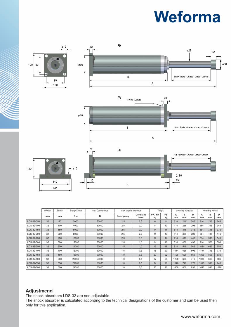
AdjustmendThe shock absorbers LDS-32 are non adjustable.The shock absorber is calculated according to the technical designations of the customer and can be used then only for this application.
mm mm Nm N Emergency Constant Load
FV / FHkg
FBkg
Amm
Bmm
Dmm
Amm
Bmm
Dmm
LDS-32-050 32 50 2000 50000 2,5 2,5 6 8 314 216 246 314 216 246
LDS-32-100 32 100 4000 50000 2,5 2,0 8 10 414 266 296 464 316 346
LDS-32-150 32 150 6000 50000 2,5 2,0 9 11 514 316 346 564 346 376
LDS-32-200 32 200 8000 50000 2,5 2,0 11 13 614 366 396 664 416 446
LDS-32-250 32 250 10000 50000 2,0 1,0 12 14 714 416 446 814 516 546
LDS-32-300 32 300 12000 50000 2,0 1,0 14 16 814 466 496 914 566 596
LDS-32-350 32 350 14000 50000 1,5 1,0 16 18 914 516 546 1024 626 656
LDS-32-400 32 400 16000 50000 1,5 0,5 18 20 1014 566 596 1194 746 776
LDS-32-450 32 450 18000 50000 1,0 0,5 20 22 1126 626 656 1306 806 836
LDS-32-500 32 500 20000 50000 1,0 0,5 22 24 1236 686 716 1386 836 866
LDS-32-550 32 550 22000 50000 1,0 0,5 24 26 1346 746 776 1516 916 946
LDS-32-600 32 600 24000 50000 1,0 0,5 26 28 1456 806 836 1646 996 1026
øPiston Stroke Energy/Stroke max. Counterforce max. angular tolerance ° Weight Mounting: horizontal Mounting: vertical

www.weforma.com
FeaturesApplications:- Automated warehouses, Stacker cranes, Cranes
Deceleration characteristics:- Customer special
Coating: - Standard: Housing zinc plated- Outdoor: Housing and seal bushing painted conforming to DIN ISO 12944-C5L Piston rod: nickel (30 µm) and harchrome (20 µm) plated
Packaging:- Wooden boxes; depending on national regulations according to ISPM 15
RoHS-conform:- Directive 2002/95/EC
Extended Life Cycle:- Piston rod: hard chrome-plated- Seal bushing from high strength aluminium- Special Seals + Oils
Temperature:Standard: -20°C -...+80°CLow-temperature: -40°C-...+60°CHigh-temperature: 0°C-...+100°C

www.weforma.com
D F ø E1LDS 32 39,5 18 31
LDS 32Stroke A
mm mm50 380
100 480150 580200 680250 780300 935350 1035400 1135450 1245500 1355550 1465600 1575
LDS 32ØG 55 mm
ØF 120 mm
Order no. N
U max = 10 ... 30V DC
I max = 200mA
Sn = dependent on a magnetic field
short-circuit protection
reverse polarityprotection
L+
A
L-
BN
BK
BU
NO
PNP
M
Proximity Switch
Stop Cap
Accessories
Protection Bellow
www.weforma.com
øD
L
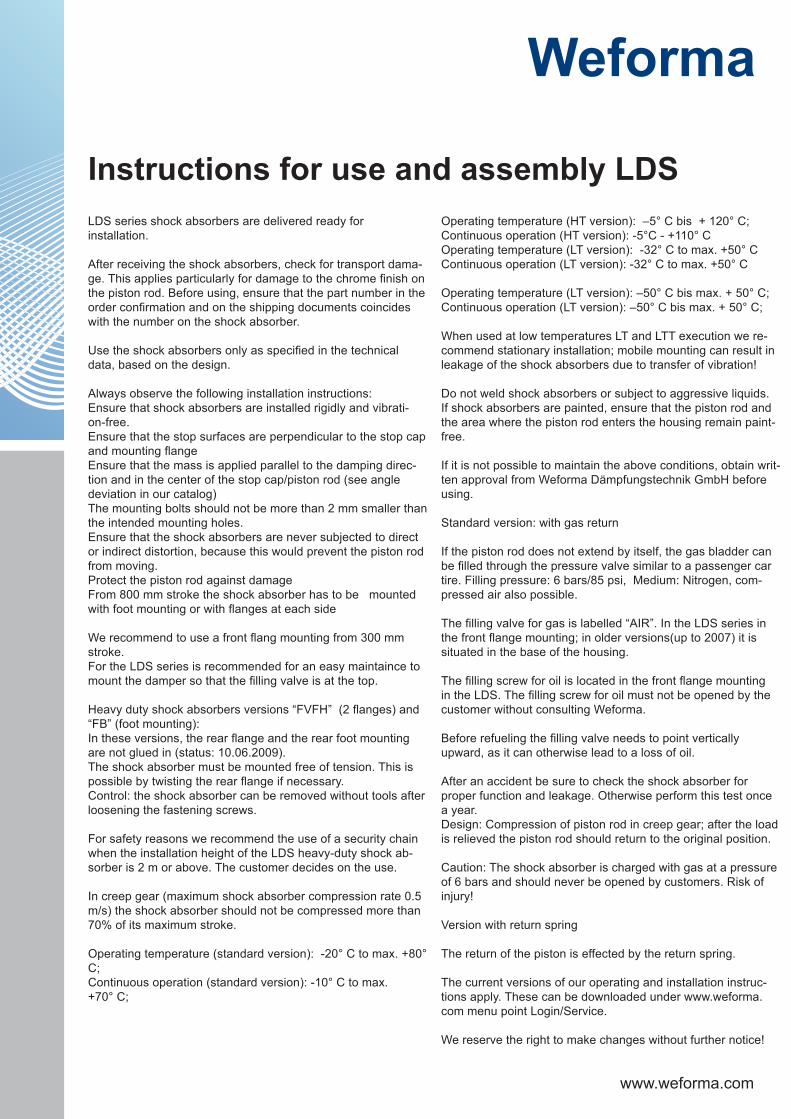
Application: Shock absorber against Shock absorber
For safety reasons we recommend the use of a security chain when the installation height of the LDS / HLS heavy-duty shock absorber is 2 m or above.
(Stroke: -10 mm)
L øDLDS 32 32 79
ø DLDS 32 70
Security Chain
Enlarged Stop Cap Metal Wiper
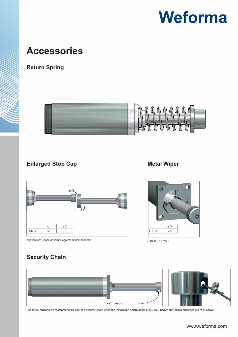
Return Spring
Accessories

www.weforma.com
Stroke A F G H J øK L M Pmm mm mm mm mm mm mm mm mm mm
LDS-32-050 50 398 38,1 16,3 35 38,1 20 38 25 38
LDS-32-100 100 498 38,1 16,3 35 38,1 20 38 25 38
LDS-32-150 150 598 38,1 16,3 35 38,1 20 38 25 38
LDS-32-200 200 698 38,1 16,3 35 38,1 20 38 25 38
LDS-32-250 250 798 38,1 16,3 35 38,1 20 38 25 38
LDS-32-300 300 898 38,1 16,3 35 38,1 20 38 25 38
DIMENSIONS
Clevis Mounting
Accessories
www.weforma.com
Operating temperature (HT version): –5° C bis + 120° C; Continuous operation (HT version): -5°C - +110° COperating temperature (LT version): -32° C to max. +50° C Continuous operation (LT version): -32° C to max. +50° C
Operating temperature (LT version): –50° C bis max. + 50° C; Continuous operation (LT version): –50° C bis max. + 50° C;
When used at low temperatures LT and LTT execution we re-commend stationary installation; mobile mounting can result in leakage of the shock absorbers due to transfer of vibration!
Do not weld shock absorbers or subject to aggressive liquids. If shock absorbers are painted, ensure that the piston rod and the area where the piston rod enters the housing remain paint-free.
If it is not possible to maintain the above conditions, obtain writ-ten approval from Weforma Dämpfungstechnik GmbH before using.
Standard version: with gas return
If the piston rod does not extend by itself, the gas bladder can be filled through the pressure valve similar to a passenger car tire. Filling pressure: 6 bars/85 psi, Medium: Nitrogen, com-pressed air also possible.
The filling valve for gas is labelled “AIR”. In the LDS series in the front flange mounting; in older versions(up to 2007) it is situated in the base of the housing.
The filling screw for oil is located in the front flange mounting in the LDS. The filling screw for oil must not be opened by the customer without consulting Weforma.
Before refueling the filling valve needs to point vertically upward, as it can otherwise lead to a loss of oil.
After an accident be sure to check the shock absorber for proper function and leakage. Otherwise perform this test once a year.Design: Compression of piston rod in creep gear; after the load is relieved the piston rod should return to the original position.
Caution: The shock absorber is charged with gas at a pressure of 6 bars and should never be opened by customers. Risk of injury!
Version with return spring
The return of the piston is effected by the return spring.
The current versions of our operating and installation instruc-tions apply. These can be downloaded under www.weforma.com menu point Login/Service.
We reserve the right to make changes without further notice!
LDS series shock absorbers are delivered ready for installation.
After receiving the shock absorbers, check for transport dama-ge. This applies particularly for damage to the chrome finish on the piston rod. Before using, ensure that the part number in the order confirmation and on the shipping documents coincides with the number on the shock absorber.
Use the shock absorbers only as specified in the technical data, based on the design.
Always observe the following installation instructions:Ensure that shock absorbers are installed rigidly and vibrati-on-free.Ensure that the stop surfaces are perpendicular to the stop cap and mounting flangeEnsure that the mass is applied parallel to the damping direc-tion and in the center of the stop cap/piston rod (see angle deviation in our catalog)The mounting bolts should not be more than 2 mm smaller than the intended mounting holes. Ensure that the shock absorbers are never subjected to direct or indirect distortion, because this would prevent the piston rod from moving.Protect the piston rod against damageFrom 800 mm stroke the shock absorber has to be mounted with foot mounting or with flanges at each side
We recommend to use a front flang mounting from 300 mm stroke.For the LDS series is recommended for an easy maintaince to mount the damper so that the filling valve is at the top.
Heavy duty shock absorbers versions “FVFH” (2 flanges) and “FB” (foot mounting): In these versions, the rear flange and the rear foot mounting are not glued in (status: 10.06.2009). The shock absorber must be mounted free of tension. This is possible by twisting the rear flange if necessary. Control: the shock absorber can be removed without tools after loosening the fastening screws.
For safety reasons we recommend the use of a security chain when the installation height of the LDS heavy-duty shock ab-sorber is 2 m or above. The customer decides on the use.
In creep gear (maximum shock absorber compression rate 0.5 m/s) the shock absorber should not be compressed more than 70% of its maximum stroke.
Operating temperature (standard version): -20° C to max. +80° C; Continuous operation (standard version): -10° C to max. +70° C;
Instructions for use and assembly LDS

www.weforma.com
Attention!Before Installation, commissioning, servicing and repair the date sheet is to be noticed. Realisation of the works only by trained, introduced specialist staff.
Electric connections according to the suitable national regulation.for Germany: VDE regulation VD E0100
Before all repair, and servicing works the energy supplies (main switch, etc.) are to be switched off! Moreo-ver, measures are necessary, around unintentional Reconnect to prevent, e.g., in the main switch a suitable warning „servicing works“, „repair works“ etc. attach.
Designated useCheck before installation and use whether the type name on the damper or on the packaging with thesuitable name on the delivery note agreesIndustrial shock absorbers are maintenance-free and ready with installation
• Moved masses Can start with the installation of the shock absorbers by unintentional for injuries and body damages lead. Moved masses against unintentional procedure protect.
• The dampers can be inexpedient for the application and show no sufficient damping effect. Before the installation check the suitable suitability of the shock absorbers
• At the company beyond the allowed temperature area the damper can lose his function. To temperature area absolutely keep. Shock absorbers because of the warm radiotherapy do not varnish
• Fluide, gases and dirty particle in the surroundings can attack the poetry system of the shock absorber or destroy and lead to the functional financial loss of the shock absorber. Piston rod and poetry system against outside funds in the surroundings protect or isolate.
• Damages of the piston rod surface can destroy the Poetry system. Piston rod are not greasy, oil etc. and before dirty particles protect.
• the piston rod can be torn out from the damper. The piston rod do not load on train tension• Shock absorber can break off in demand. The connection construction always lay out in such a way that the at most appearing
forces with sufficient security can be recorded. The maximum supporting forces performed in the calculation programme can deviate from the later really appearing supporting forces, because these are based on theoretical values.
• A setting of the shock absorbers to the respective application is necessary compelling. A wrong setting of the damping leads to a raised machine charge and to an untimely financial loss of the shock absorber
LiabilityDue to the number of possible uses of our products and the conditions of use that lie outside of our scope of influence, we accept no liability as to whether the purchase object is suitable for the Client‘s intended purpo-se. The verification to this effect, in particular the verification as to whether the purchase object is suitable for the planned use, is the responsibility of the Client alone, unless expressly agreed otherwise in writing.
For the reasons we accept no liability for the suitability of the purchase object for the purpose intended by the Client, except in cases of intent or gross negligence.
With damages, the not designated use and from high-handed, in these instructions do not originate to inten-ded interventions, any guarantee and liability claim goes out towards the manufacturer.
GuaranteeBy non-use of the original spare parts the guarantee claim goes out.
Environment protectionBy the exchange from damaged parts is to be respected to a proper disposal.
Important information