december 6-10, 2004 hotel kirchbühl, grindelwald...
TRANSCRIPT
3rd International Workshop on Beam Orbit Stabilization - IWBS2004December 6-10, 2004
Hotel Kirchbühl, Grindelwald, SWITZERLAND
Orbit Stabilization
at
Taiwan Light Source
Kuo-Tung Hsu
December 6, 2004
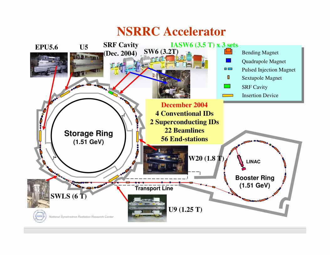
NSRRC Accelerator
Storage Ring(1.51 GeV)
Booster Ring
(1.51 GeV)
LINAC
Transport Line
Bending Magnet
Quadrupole Magnet
Pulsed Injection Magnet
Sextupole Magnet
SRF Cavity
Insertion Device
BM2
BM1
W20 (1.8 T)
U9 (1.25 T)
SWLS (6 T)
EPU5.6 U5 SRF Cavity
(Dec. 2004) SW6 (3.2T)IASW6 (3.5 T) x 3 sets
December 2004
4 Conventional IDs
2 Superconducting IDs
22 Beamlines
56 End-stations
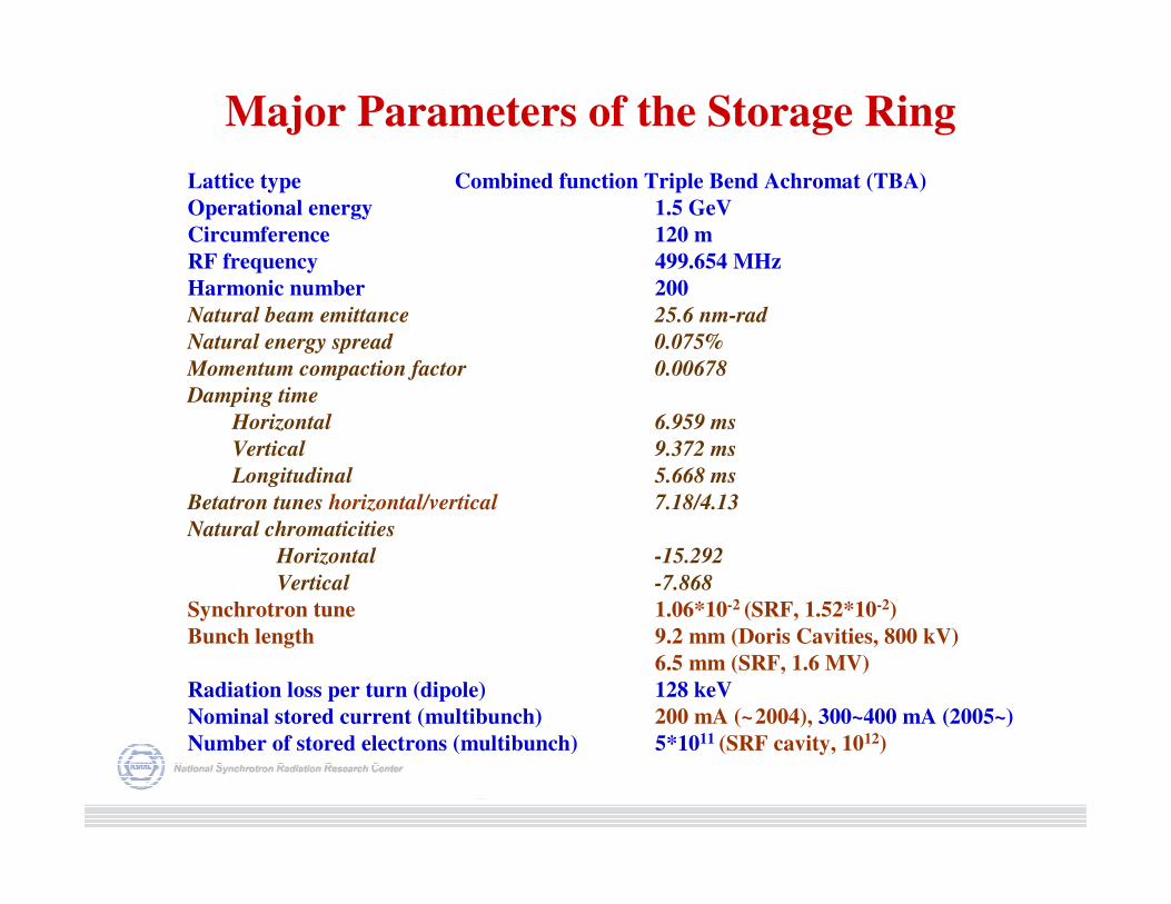
Lattice type Combined function Triple Bend Achromat (TBA)
Operational energy 1.5 GeV
Circumference 120 m
RF frequency 499.654 MHz
Harmonic number 200
Natural beam emittance 25.6 nm-rad
Natural energy spread 0.075%
Momentum compaction factor 0.00678
Damping time
Horizontal 6.959 ms
Vertical 9.372 ms
Longitudinal 5.668 ms
Betatron tunes horizontal/vertical 7.18/4.13
Natural chromaticities
Horizontal -15.292
Vertical -7.868
Synchrotron tune 1.06*10-2 (SRF, 1.52*10-2)
Bunch length 9.2 mm (Doris Cavities, 800 kV)
6.5 mm (SRF, 1.6 MV)
Radiation loss per turn (dipole) 128 keV
Nominal stored current (multibunch) 200 mA (~2004), 300~400 mA (2005~)
Number of stored electrons (multibunch) 5*1011 (SRF cavity, 1012)
Major Parameters of the Storage Ring
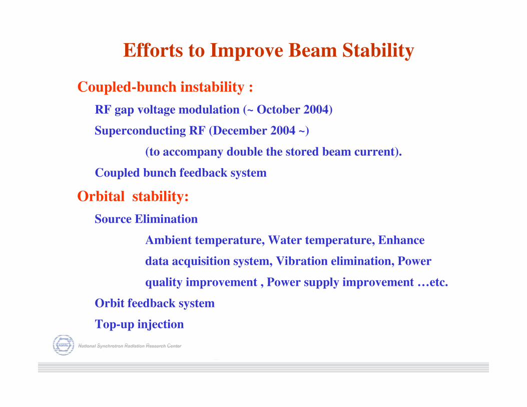
Efforts to Improve Beam Stability
Coupled-bunch instability :
RF gap voltage modulation (~ October 2004)
Superconducting RF (December 2004 ~)
(to accompany double the stored beam current).
Coupled bunch feedback system
Orbital stability:
Source Elimination
Ambient temperature, Water temperature, Enhance
data acquisition system, Vibration elimination, Power
quality improvement , Power supply improvement …etc.
Orbit feedback system
Top-up injection
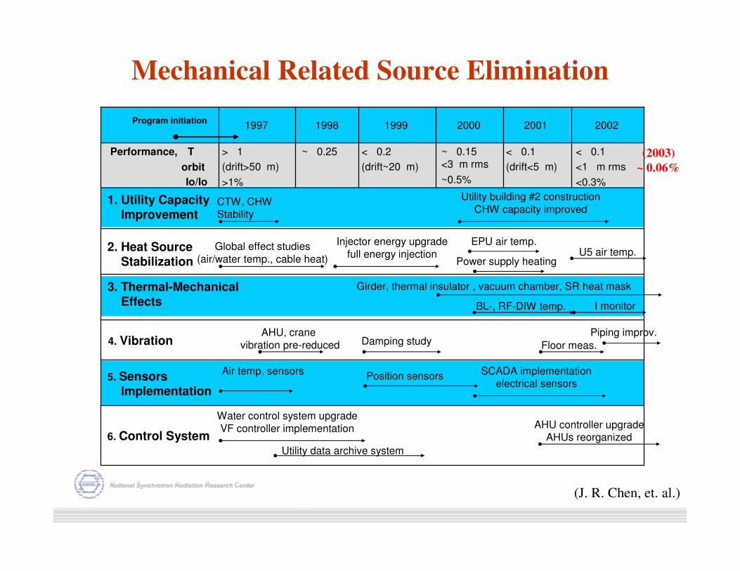
4. Vibration
6. Control System
5. SensorsImplementation
3. Thermal-Mechanical Effects
2. Heat SourceStabilization
1. Utility Capacity Improvement
< 0.1
<1 m rms
<0.3%
< 0.1
(drift<5 m)
~ 0.15<3 m rms
~0.5%
< 0.2
(drift~20 m)
~ 0.25> 1
(drift>50 m)
>1%
Performance, T
orbit
Io/Io
200220012000199919981997
Utility building #2 construction
CHW capacity improvedCTW, CHWStability
Injector energy upgrade
full energy injection
EPU air temp.U5 air temp.
SCADA implementationelectrical sensors
Water control system upgrade
VF controller implementation
Utility data archive system
AHU controller upgradeAHUs reorganized
Air temp. sensorsPosition sensors
Global effect studies
(air/water temp., cable heat)
Girder, thermal insulator , vacuum chamber, SR heat mask
BL-, RF-DIW temp.
AHU, crane
vibration pre-reduced Damping study Floor meas.
Piping improv.
Program initiation
Power supply heating
I monitor
Mechanical Related Source Elimination
(2003)
~ 0.06%
(J. R. Chen, et. al.)
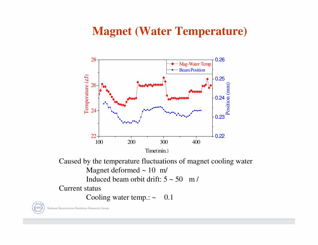
Magnet (Water Temperature)
100 200 300 40022
24
26
28Mag-Water Temp.
Beam Position
Time(min.)
Tem
per
ature
(¢J)
0.22
0.23
0.24
0.25
0.26
Posi
tion (
mm
)
Caused by the temperature fluctuations of magnet cooling water
Magnet deformed ~ 10 m/
Induced beam orbit drift: 5 ~ 50 m /
Current status
Cooling water temp.: ~ 0.1
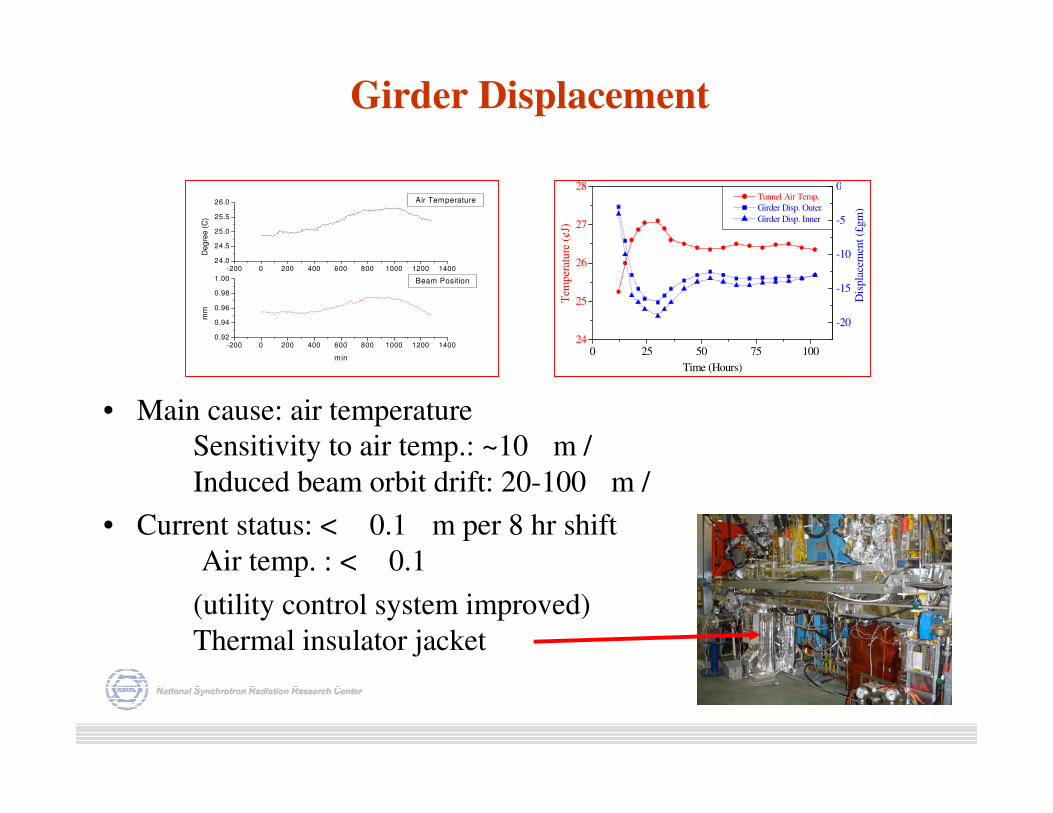
Girder Displacement
• Main cause: air temperature
Sensitivity to air temp.: ~10 m /
Induced beam orbit drift: 20-100 m /
• Current status: < 0.1 m per 8 hr shift
Air temp. : < 0.1
(utility control system improved)
Thermal insulator jacket
-200 0 200 400 600 800 1000 1200 14000.92
0.94
0.96
0.98
1.00
-200 0 200 400 600 800 1000 1200 140024.0
24.5
25.0
25.5
26.0
Beam Position
mm
min
Air TemperatureD
egre
e (
C)
0 25 50 75 10024
25
26
27
28
Dis
pla
cem
ent
(£gm
)
Tunnel Air Temp.
Girder Disp. Outer
Girder Disp. Inner
Time (Hours)
Tem
per
ature
(¢J)
-20
-15
-10
-5
0
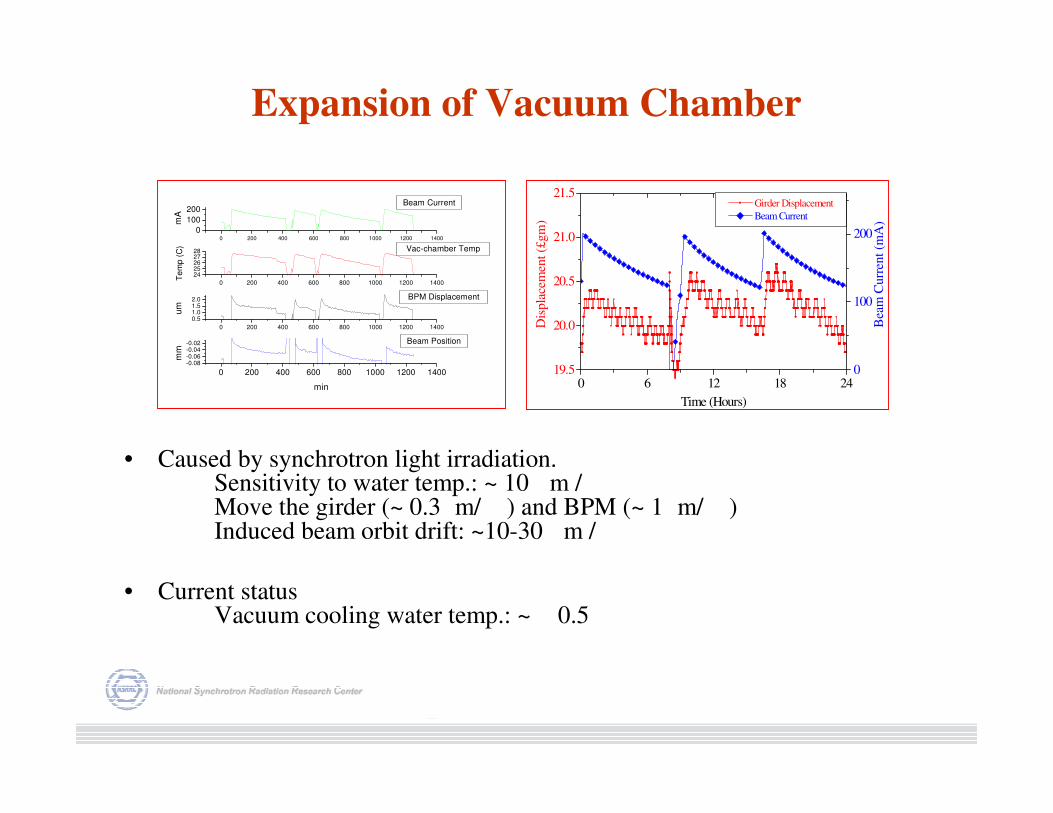
Expansion of Vacuum Chamber
• Caused by synchrotron light irradiation.Sensitivity to water temp.: ~ 10 m /Move the girder (~ 0.3 m/ ) and BPM (~ 1 m/ )Induced beam orbit drift: ~10-30 m /
• Current statusVacuum cooling water temp.: ~ 0.5
0 6 12 18 2419.5
20.0
20.5
21.0
21.5Girder Displacement
Beam Current
Time (Hours)
Dis
pla
cem
ent
(£gm
)
0
100
200
Bea
m C
urr
ent
(mA
)
0 200 400 600 800 1000 1200 1400
-0.08-0.06-0.04-0.02
0 200 400 600 800 1000 1200 1400
0.51.01.52.0
0 200 400 600 800 1000 1200 1400
2425262728
0 200 400 600 800 1000 1200 1400
0
100
200
Beam Position
mm
min
BPM Displacement
um
Vac-chamber Temp
Te
mp
(C
)
Beam Current
mA
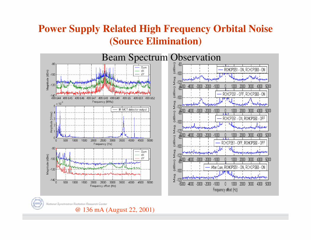
Power Supply Related High Frequency Orbital Noise
(Source Elimination)
@ 136 mA (August 22, 2001)
Beam Spectrum Observation
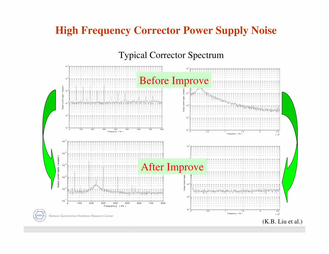
High Frequency Corrector Power Supply Noise
0 10 0 2 00 3 00 40 0 5 00 6 00 7 00 8 0010
-7
10-6
10-5
10-4
10-3
10-2
F req ue nc y ( H z )
Outp
ut
curr
ent
ripp
le
( am
pere
)
0 0.5 1 1.5 2 2.5
x 104
10-7
10-6
10-5
10-4
10-3
10-2
Frequency ( Hz )
Outp
ut
curr
ent
ripple
(
am
pere
)
Typical Corrector Spectrum
0 100 200 300 400 500 600 700 80010
-7
10-6
10-5
10-4
10-3
10-2
Frequenc y ( Hz )
Ou
tput
curr
ent
ripple
(
am
pere
)
0 0.5 1 1.5 2 2.5
x 104
10-7
10-6
10-5
10-4
10-3
10-2
Frequency ( Hz )
Ou
tput
curr
ent
ripple
(
am
pere
)
Before Improve
After Improve
(K.B. Liu et al.)
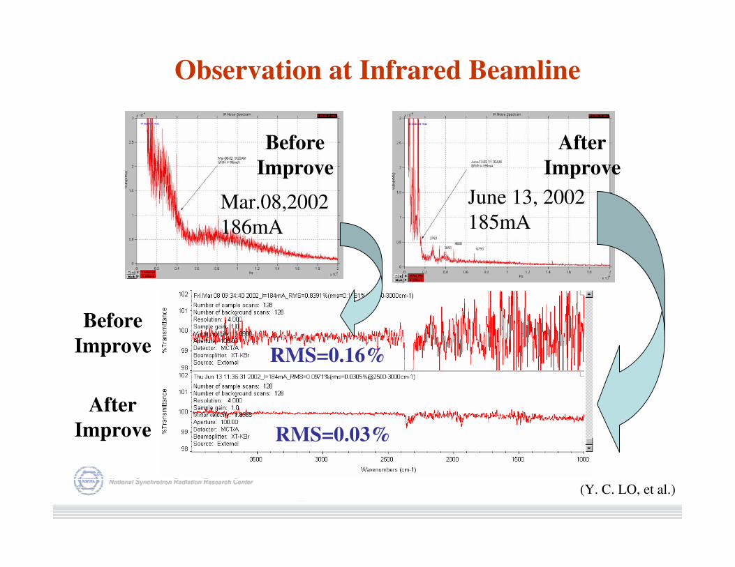
Before
Improve
RMS=0.03%
RMS=0.16%
Mar.08,2002
186mA
June 13, 2002
185mA
Observation at Infrared Beamline
After
Improve
Before
Improve
After
Improve
(Y. C. LO, et al.)
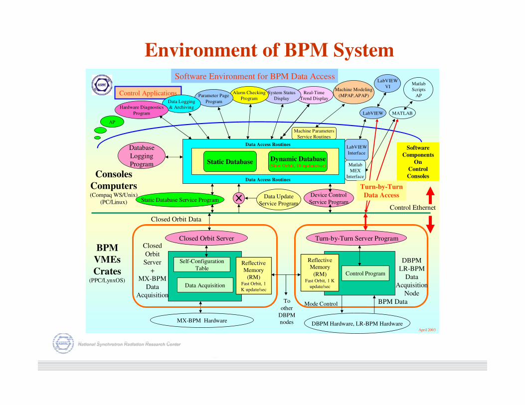
Software Environment for BPM Data Access
Closed Orbit Server
Static Database Dynamic Database(Slow Orbit, 10 update/sec)
Device Control
Service ProgramStatic Database Service ProgramData Update
Service Program
Database
Logging
Program
Real-Time
Trend Display
LabVIEW
Interface
Matlab
MEX
Interface
MX-BPM Hardware
Control Ethernet
Software
Components
On
Control
Consoles
BPM
VMEs
Crates(PPC/LynxOS)
Consoles
Computers(Compaq WS/Unix)
(PC/Linux)
Self-Configuration
Table
Data Acquisition
Reflective
Memory
(RM)Fast Orbit, 1
K update/sec
Machine Parameters
Service Routines
Machine Modeling
(MPAP,APAP)Control Applications
Data Access Routines
Data Access Routines
April 2003
Matlab
Scripts
AP
MATLAB
LabVIEW
VI
LabVIEW
System Status
Display
Alarm Checking
ProgramParameter Page
ProgramData Logging
& ArchivingHardware Diagnostics
Program
AP
Turn-by-Turn Server Program
Closed Orbit Data
Reflective
Memory
(RM)Fast Orbit, 1 K
update/sec
DBPM Hardware, LR-BPM Hardware
Mode Control BPM Data
Control Program
To
other
DBPM
nodes
Closed
Orbit
Server
+
MX-BPM
Data
Acquisition
DBPM
LR-BPM
Data
Acquisition
Node
Turn-by-Turn
Data Access
Environment of BPM System
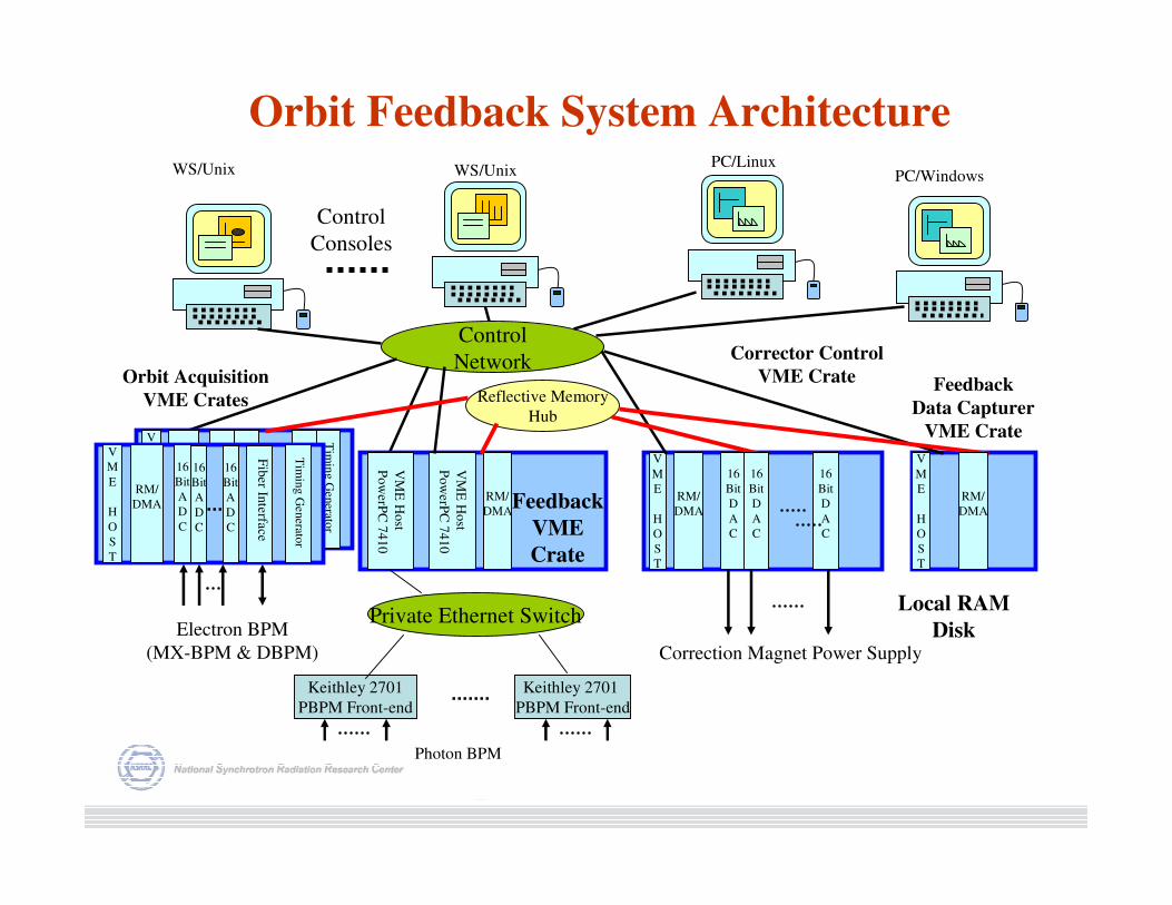
Orbit Feedback System Architecture
Control
Network
Control
Consoles
PC/Linux
V
M
E
H
O
S
T
16
Bit
D
A
C
RM/
DMA
Private Ethernet Switch
Reflective Memory
Hub
Keithley 2701
PBPM Front-end
Keithley 2701
PBPM Front-end
Feedback
VME
Crate
Corrector Control
VME CrateOrbit Acquisition
VME Crates
RM/
DMA
16
Bit
D
A
C
16
Bit
D
A
C
Electron BPM
(MX-BPM & DBPM) Correction Magnet Power Supply
Photon BPM
V
M
E
H
O
S
T
RM/
DMA
16
Bit
A
D
C
16
Bit
A
D
C
16
Bit
A
D
C
Tim
ing G
enerato
r
VM
E H
ost
Po
werP
C 7
410
RM/
DMA
V
M
E
H
O
S
T
Feedback
Data Capturer
VME Crate
VM
E H
ost
Po
werP
C 7
410
PC/WindowsWS/UnixWS/Unix
Local RAM
Disk
V
M
E
H
O
S
T
RM/
DMA
16
Bit
A
D
C
16
Bit
A
D
C
Tim
ing G
enerato
r
16
Bit
A
D
C
Fib
er In
terfa
ce
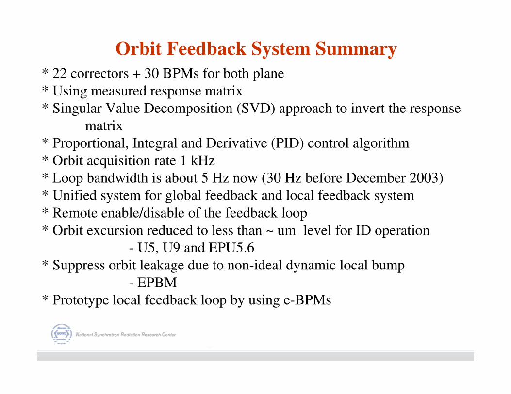
Orbit Feedback System Summary
* 22 correctors + 30 BPMs for both plane
* Using measured response matrix
* Singular Value Decomposition (SVD) approach to invert the response
matrix
* Proportional, Integral and Derivative (PID) control algorithm
* Orbit acquisition rate 1 kHz
* Loop bandwidth is about 5 Hz now (30 Hz before December 2003)
* Unified system for global feedback and local feedback system
* Remote enable/disable of the feedback loop
* Orbit excursion reduced to less than ~ um level for ID operation
- U5, U9 and EPU5.6
* Suppress orbit leakage due to non-ideal dynamic local bump
- EPBM
* Prototype local feedback loop by using e-BPMs
Orbit Feedback System Summary (cont.)
* DSP feedback engine was replaced by general purpose PPC module
User friendly development environment
Lift maintenance difficults
Slightly increase jitter < 50 µsec (DSP < 10 µsec)
* Robustness enhancement of the feedback loop
BPM Check
RMS, data change rate, …etc
Limited correct setting range
Problems and Plan of the Orbit Feedback System
Major Problems :
* Loop bandwidth is too small right now
=> cannot eliminate mechanical related oscillation
=> Limited gap/phase changing speed of IDs
Short-term Plans:
* Increase sampling rate o 2 kHz to 4 kHz
* Modify corrector power supply regulation loop
* Increase loop bandwidth > 100 Hz
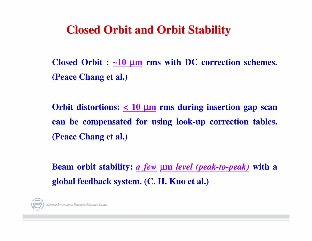
Closed Orbit : ~10 µµµµm rms with DC correction schemes.
(Peace Chang et al.)
Orbit distortions: < 10 µµµµm rms during insertion gap scan
can be compensated for using look-up correction tables.
(Peace Chang et al.)
Beam orbit stability: a few µµµµm level (peak-to-peak) with a
global feedback system. (C. H. Kuo et al.)
Closed Orbit and Orbit StabilityClosed Orbit and Orbit Stability
e-
Power
Supply
#1
Power
Supply
#2
Power
Supply
#4
Power
Supply
#3
EPBM
Model
Enable
Bump
Amplitude
Control
(0-5 V)
Bump Coefficient
(± 10 V)
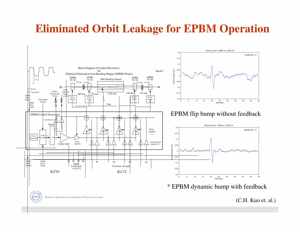
Block Diagram of Control Electronics for
Elliptical Polarization from Bending Magnet (EPBM) ProjectDRAFT
Ratio
Amplifier
x 4
#1 #4#3#2
BM2 Bending MagnetEPBM VC #1
EPBM VC #2
EPBM VC #3
EPBM VC #4
EPBM Control Electronics
SYNC to
Experimental
Station
Clock
Generator
12 12
Corrector Strength
ILC12ILC03
#1 #2 #3 #4#1 #2 #3 #4
Line Driver x 2
EPROM
12 Bits
Counter
t1
t2
t2 : user specify
Ratio
Amplifier Instrumentation
Amplifier x 812 Bits DAC
++ + +
t1 : 40 msec
Polarization
Control
EPBM
Mode
Request
EPBM
Model
Request
EPBM
Mode
Enable
3.4o
1220 mm460 mm 375 mm 540 mm 345 mm
325 mm 135 mm 170 mm 175 mm
-0.2
-0.15
-0.1
-0.05
0
0.05
0.1
0.15
0.2
0 5 10 15 20 25 30 35 40 45 50
Vert
ical P
ositio
n (
mm
)
BPM Index
Difference Orbit - EPBM 'on', DGFB 'off'
"ep0925f.dat"
-0.2
-0.15
-0.1
-0.05
0
0.05
0.1
0.15
0.2
0 5 10 15 20 25 30 35 40 45 50
Vert
ical P
ositio
n (
mm
)
BPM Index
Difference Orbit - EPBM 'on', DGFB 'on'
"ep0925g.dat"
* EPBM dynamic bump with feedback
EPBM flip bump without feedback
Eliminated Orbit Leakage for EPBM Operation
(C.H. Kuo et. al.)
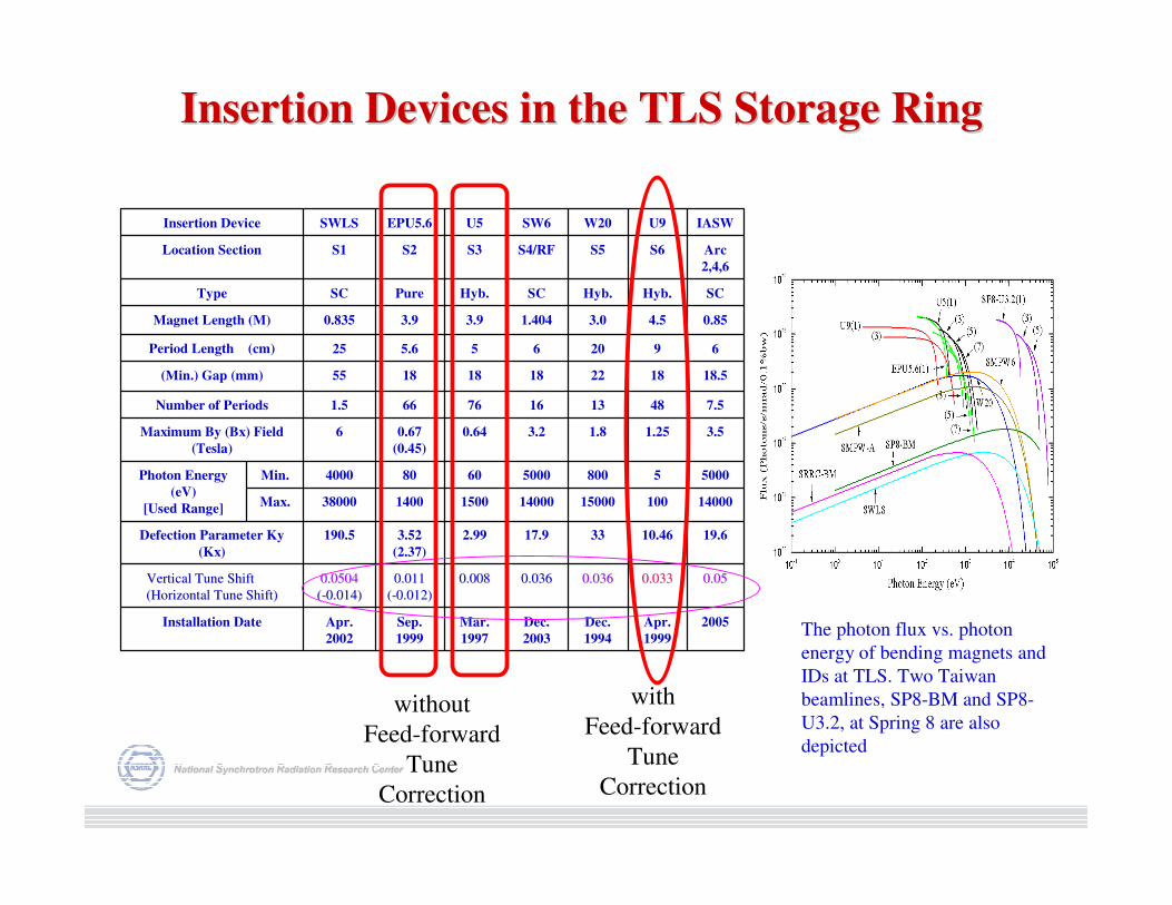
Insertion Devices in the TLS Storage RingInsertion Devices in the TLS Storage Ring
2005Apr.
1999
Dec.
1994
Dec.
2003
Mar.
1997
Sep.
1999
Apr.
2002
Installation Date
0.050.050.0330.0330.0360.0360.0360.0360.0080.0080.0110.011
((--0.012)0.012)
0.05040.0504
((--0.014)0.014)
Vertical Tune Shift Vertical Tune Shift
(Horizontal Tune Shift)(Horizontal Tune Shift)
19.610.463317.92.993.52
(2.37)
190.5Defection Parameter Ky
(Kx)
1400010015000140001500140038000Max.
50005800500060804000Min.Photon Energy
(eV)
[Used Range]
3.51.251.83.20.640.67
(0.45)
6Maximum By (Bx) Field
(Tesla)
7.548131676661.5Number of Periods
18.5182218181855(Min.) Gap (mm)
6920655.625Period Length (cm)
0.854.53.01.4043.93.90.835Magnet Length (M)
SCHyb.Hyb.SCHyb.PureSCType
Arc
2,4,6
S6S5S4/RFS3S2S1Location Section
IASWU9W20SW6U5EPU5.6SWLSInsertion Device
The photon flux vs. photon
energy of bending magnets and
IDs at TLS. Two Taiwan
beamlines, SP8-BM and SP8-
U3.2, at Spring 8 are also
depicted
with
Feed-forward
Tune
Correction
without
Feed-forward
Tune
Correction
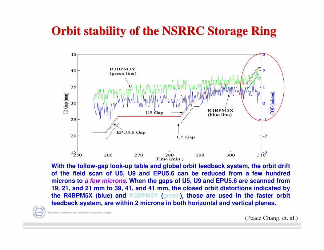
Orbit stability of the NSRRC Storage RingOrbit stability of the NSRRC Storage Ring
With the follow-gap look-up table and global orbit feedback system, the orbit drift
of the field scan of U5, U9 and EPU5.6 can be reduced from a few hundred
microns to a few microns. When the gaps of U5, U9 and EPU5.6 are scanned from
19, 21, and 21 mm to 39, 41, and 41 mm, the closed orbit distortions indicated by
the R4BPM5X (blue) and R3BPM3Y (green), those are used in the faster orbit
feedback system, are within 2 microns in both horizontal and vertical planes.
(Peace Chang, et. al.)
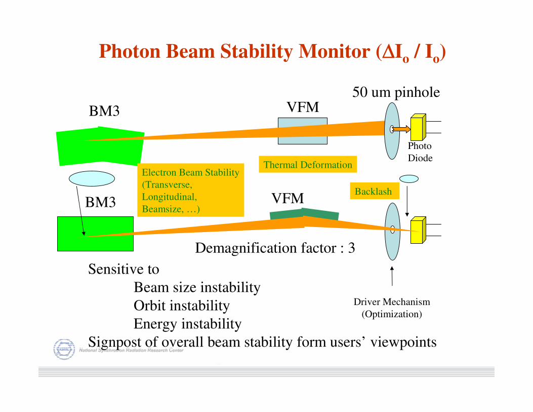
Photon Beam Stability Monitor (∆∆∆∆Io / Io)
BM3
BM3
VFM
VFM
50 um pinhole
Sensitive to
Beam size instability
Orbit instability
Energy instability
Signpost of overall beam stability form users’ viewpoints
Demagnification factor : 3
Photo
DiodeThermal Deformation
Backlash
Driver Mechanism
(Optimization)
Electron Beam Stability
(Transverse,
Longitudinal,
Beamsize, …)
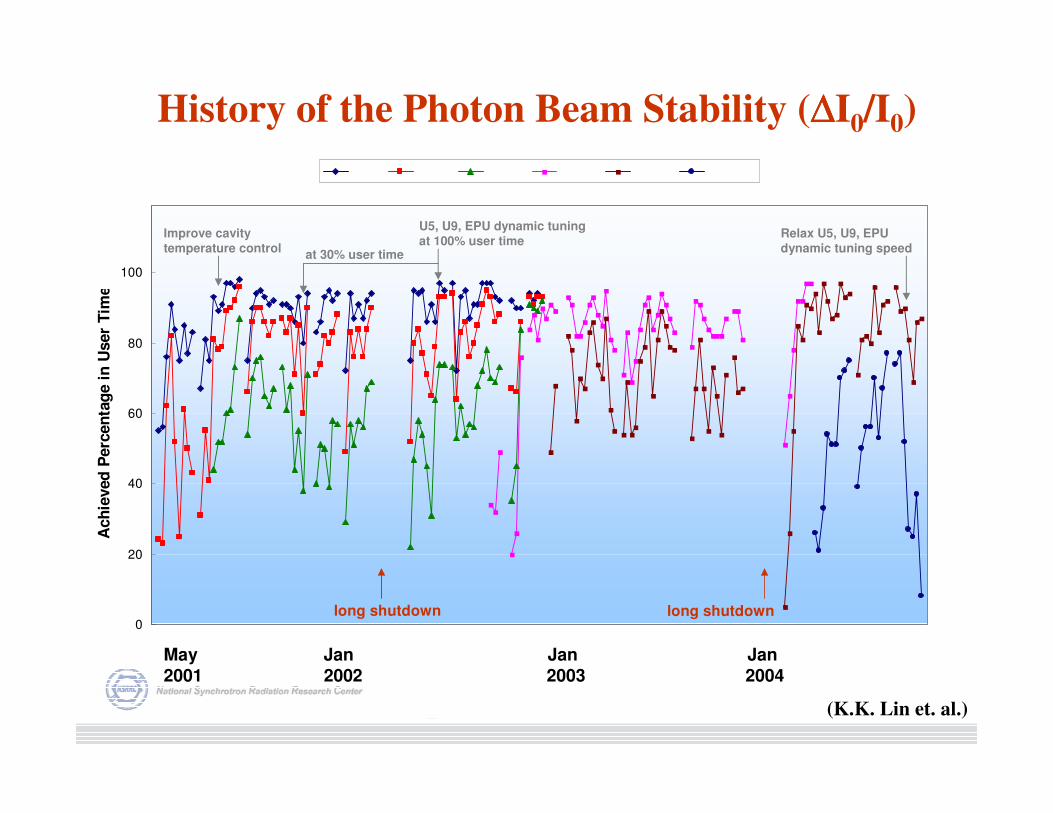
History of the Photon Beam Stability (∆∆∆∆I0/I0)
May Jan Jan Jan2001 2002 2003 2004
0
20
40
60
80
100
Ach
ieved
Perc
en
tag
e i
n U
ser
Tim
e
long shutdown long shutdown
Improve cavity
temperature controlat 30% user time
U5, U9, EPU dynamic tuning
at 100% user timeRelax U5, U9, EPU
dynamic tuning speed
(K.K. Lin et. al.)
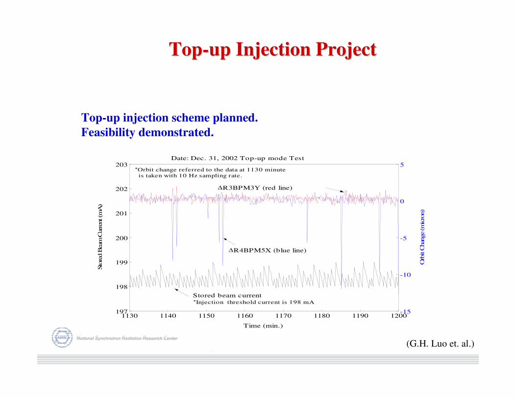
1130 1140 1150 1160 1170 1180 1190 1200197
198
199
200
201
202
203
Time (min.)
Sto
red B
eam
Curren
t (m
A)
-15
-10
-5
0
5
Orb
it C
han
ge
(mic
ron)
Date: Dec. 31, 2002 Top-up mode Test
∆R4BPM5X (blue line)
*Orbit change referred to the data at 1130 minute is taken with 10 Hz sampling rate.
∆R3BPM3Y (red line)
Stored beam current *Injection threshold current is 198 mA
Top-up injection scheme planned.
Feasibility demonstrated.
(G.H. Luo et. al.)
TopTop--up Injection Projectup Injection Project
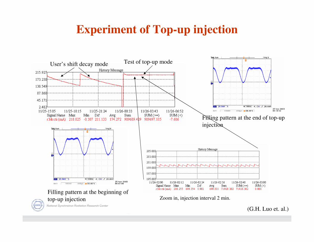
Experiment of Top-up injection
Filling pattern at the beginning of
top-up injection
Filling pattern at the end of top-up
injection
User’s shift decay mode Test of top-up mode
Zoom in, injection interval 2 min.
(G.H. Luo et. al.)
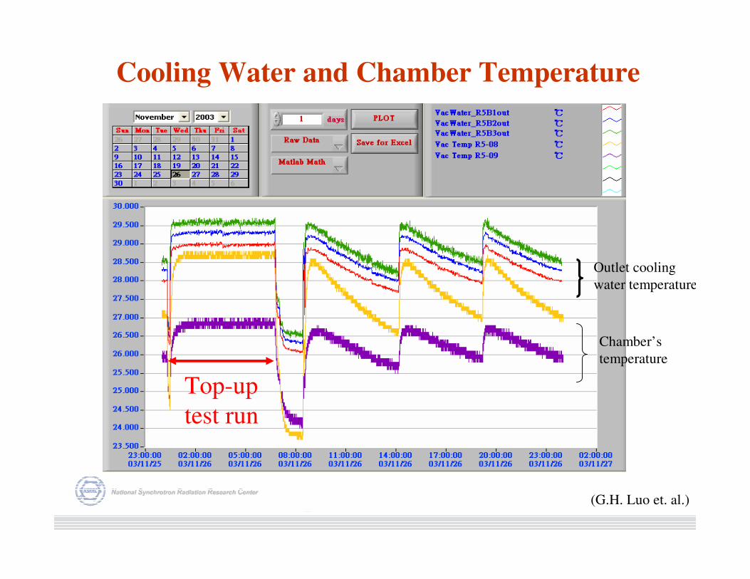
Cooling Water and Chamber Temperature
Outlet cooling
water temperature
Chamber’s
temperature
Top-up
test run
(G.H. Luo et. al.)

Compound Displacement of the of Beam Position
Monitor Reading
Stored beam current
in mAR1 BPM3 X-displacement
in µm
R1 BPM3 Y-
displacement in µm
δx ~15 µm
δy ~5 µm
-Intensity dependency of BPM electronic and BPM support fixtures (~ µm)
-Filling pattern dependency of BPM electronics (~ µm)
-RF gap voltage condition variation
-BPM support structure (~ 10 µm)
-Thermal related (~ 10 µm)
Top-up test run
(G.H. Luo et. al.)
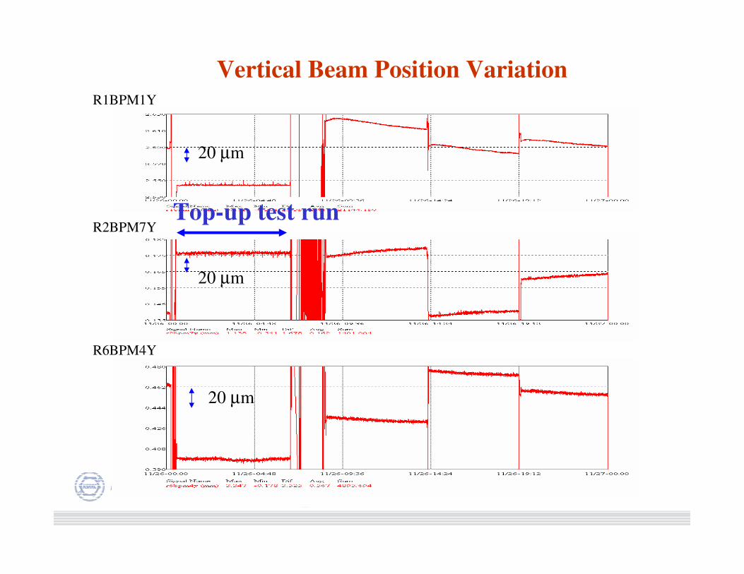
R1BPM1Y
R2BPM7Y
R6BPM4Y
Vertical Beam Position Variation
20 µm
20 µm
20 µm
Top-up test run
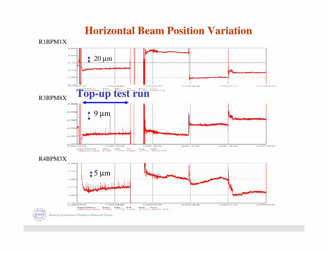
R1BPM1X
R4BPM3X
R3BPM8X
Horizontal Beam Position Variation
20 µm
9 µm
5 µm
Top-up test run
Renew 1.5 µµµµsec half-since injection kicker to reduced jitter
and to improve waveform matching .
Gate of the orbit feedback loop is a provincial solution to
remedy mismatching problem of the injection kickers.
User experiment with injection gate and without is performed,
acceptable results get up to now.
Improve gun pulser and linac performance to improve filling
pattern control.
Studies of the injector reliability, injection efficiency, and
minimization of orbit perturbation during injection, etc., are
ongoing.
Top-up operation is scheduled in late 2005.
TopTop--up Injection Planup Injection Plan
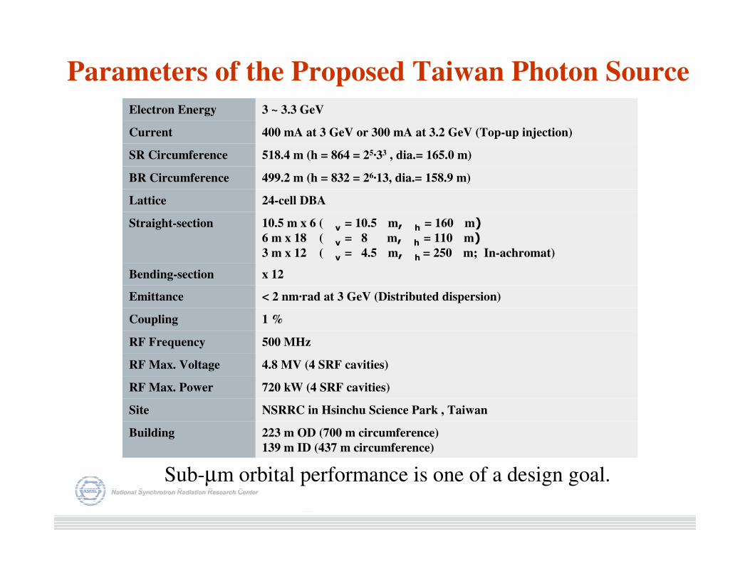
223 m OD (700 m circumference)
139 m ID (437 m circumference)
Building
NSRRC in Hsinchu Science Park , Taiwan Site
720 kW (4 SRF cavities) RF Max. Power
4.8 MV (4 SRF cavities) RF Max. Voltage
500 MHz RF Frequency
1 % Coupling
< 2 nm·rad at 3 GeV (Distributed dispersion) Emittance
x 12 Bending-section
10.5 m x 6 ( v = 10.5 m, h = 160 m) 6 m x 18 ( v = 8 m, h = 110 m) 3 m x 12 ( v = 4.5 m, h = 250 m; In-achromat)
Straight-section
24-cell DBA Lattice
499.2 m (h = 832 = 26·13, dia.= 158.9 m) BR Circumference
518.4 m (h = 864 = 25·33 , dia.= 165.0 m) SR Circumference
400 mA at 3 GeV or 300 mA at 3.2 GeV (Top-up injection) Current
3 ~ 3.3 GeVElectron Energy
Parameters of the Proposed Taiwan Photon Source
Sub-µm orbital performance is one of a design goal.
Summary
* To achieve µm (sub-µm) orbital performance is a short term goal at
TLS.
* Further develop of fast orbit feedback system is needed in
following area:
• Corrector PS improvement
• High sampling rate (~ 2 KHz/4 KHz)
• PS control interface
• BPM system improvement in engineering as well as software
functionality.
* Top-up operation mode is scheduled, beam orbit stability will be
improve further.
* Sub-µm orbital performance is one of a challenge for the newly
proposed 3 ~ 3.3 GeV Taiwan Photon Source