declaration of si te mpe com plian...
TRANSCRIPT

The followbeen dete PROJECT Table 1
Latitud
39.283
39.279
39.40
39.396
39.357
39.354
39.348
39.3484
39.3049
39.2914
39.3036
39.2855
39.2976
39.2959
39.29184
38.2890
38.2924
38.2957
39.32634
39.3236
39.3189
39.3167
39.3133
39.3053
39.2623
39.2568
39.29684
39.2917
wing sites in Termined to m
ID: NE‐MD‐
e Longi
05 ‐7
34 ‐7
31 ‐
66 ‐7
37 ‐7
52 ‐7
93 ‐7
44 ‐7
99 ‐76
04 ‐76
77 ‐76
52 ‐76
35 ‐76
76 ‐76
43 ‐76
51 ‐77
57 ‐77
84 ‐77
45 ‐76
64 ‐76
82 ‐76
79 ‐76
27 ‐76
00 ‐76
00 ‐76
18 ‐76
45 ‐76
33 ‐76
Decla
Table 1 have meet occupati
‐BALTIMOR‐S
itude Na
6.64058 DC
6.63292 DC
76.6059 DC
6.60359 DC
6.60106 DC
6.59344 DC
6.57999 DC
6.58865 DC
.595902 DC
.595882 DC
.584628 DC
.602872 DC
.599875 DC
.575223 DC
.567636 DC
.532009 WA
.521950 WA
.511160 WA
.545534 WA
.556876 WA
.564260 WA
.556624 WA
.567324 WA
.564909 WA
.490149 WA
.487201 WA
.582572 DC
.587286 DC
aration
been analyzeonal and gen
SPR
ame
C03XC013DC0
C03XC013DC0
C03XC210_1
C03XC210_3
C03XC306WA
C03XC306WA
C03XC306WA
C03XC306WA
C03XC324DC0
C03XC324DC0
C03XC324DC0
C03XC324DC0
C03XC324DC0
C03XC324DC0
C03XC324DC0
A33XC159_1
A33XC159_2
A33XC159_3
A60XC008DC
A60XC008DC
A60XC008DC
A60XC008DC
A60XC008DC
A60XC008DC
A73XC067_1
A73XC067_2
C03XC324DC0
C03XC324DC0
nofSi
ed against theeral public M
DAT
03XC122_2
03XC122_5
A65XC001_3
A65XC001_4
A65XC001_6
A65XC001_7
03XC173DC03
03XC173DC03
03XC173DC03
03XC173DC03
03XC173DC03
03XC173DC03
03XC173DC03
‐ Node 18
‐ Node 19
‐ Node 20
25XC259_1
25XC259_2
25XC259_3
25XC259_4
25XC259_5
25XC259_6
03XC173DC03
03XC173DC03
iteMP
e attached woMPE complian
TE: 05/18/15
3XC125WA33
3XC125WA33
3XC125WA33
3XC125WA33
3XC125WA33
3XC125WA33
3XC125WA33
3XC125WA33
3XC125WA33
PECom
orst‐case site ce requireme
ANTENNA
3XC910_1
3XC910_10
3XC910_2
3XC910_3
3XC910_6
3XC910_7
3XC910_9
3XC910_5
3XC910_8
mplian
parameters fents. See tabl
TYPE: Cellma
Status
Clear
Clear
Clear
Clear
Clear
Clear
Clear
Clear
Clear
Clear
Clear
Clear
Clear
Clear
Clear
Clear
Clear
Clear
Clear
Clear
Clear
Clear
Clear
Clear
Clear
Clear
Clear
Clear
nce
for MPE come below.
ax CMM‐BD‐T
Rooftop
N
N
N
N
N
N
N
N
N
N
N
N
N
N
N
N
N
N
N
N
N
N
N
N
N
N
N
N
pliance and h
TRI/65‐15/12
have

Table 2
Parameter Site‐Specific Result Compliant?
Maximum amplifier output power 43 dBm yes
Maximum antenna gain 9.6 dBi yes
Minimum horizontal distance from any general public structure
> 20 feet yes
Minimum horizontal distance to antenna for occupational MPE requirement
Not accessible horizontally yes
David C. Cotton, Jr. – Date: 2015-May-15 Professional Certification. I hereby certify that these
documents were prepared or approved by me, and that I am a duly licensed professional engineer under the laws of the
State of Maryland, License No. 36477, Expiration Date: 2016-December-10
ExteNet Systems Inc. Site ID – NE-MD-BALTIMOR-SPR Site Name – Baltimore Sprint Site Compliance Report Location: To Be Determined
Structure Type: Utility Pole Report generated date: May 15, 2015 Report by: Kobi Thompson Customer Contact: Sunday Aiyash
Site Will Be Compliant based on FCC Rules and Regulations. © 2015 Sitesafe, Inc. Arlington, VA
200 North Glebe Road, Suite 1000, Arlington, VA 22203-3728 703.276.1100 ● 703.276.1169 fax
[email protected] ● www.sitesafe.com


Table of Contents
1 EXECUTIVE SUMMARY ....................................................................................... 2
2 REGULATORY BASIS ........................................................................................... 3 2.1 FCC RULES AND REGULATIONS ............................................................................ 3 2.2 OSHA STATEMENT ................................................................................................ 4
3 SITE COMPLIANCE ............................................................................................. 5 3.1 SITE COMPLIANCE STATEMENT .............................................................................. 5 3.2 ACTIONS FOR SITE COMPLIANCE ........................................................................... 5
4 SAFETY PLAN AND PROCEDURES ...................................................................... 6
5 ANALYSIS ........................................................................................................... 7
5.1 RF EMISSIONS DIAGRAM ....................................................................................... 7
6 ANTENNA INVENTORY ..................................................................................... 10
7 ENGINEER CERTIFICATION .............................................................................. 12
APPENDIX A – STATEMENT OF LIMITING CONDITIONS ......................................... 13
APPENDIX B – ASSUMPTIONS AND DEFINITIONS................................................... 14
GENERAL MODEL ASSUMPTIONS .................................................................................... 14 USE OF GENERIC ANTENNAS ........................................................................................... 14 DEFINITIONS ................................................................................................................. 15
APPENDIX C – RULES & REGULATIONS ................................................................... 17 EXPLANATION OF APPLICABLE RULES AND REGULATIONS .................................................. 17 OCCUPATIONAL ENVIRONMENT EXPLAINED ..................................................................... 17
APPENDIX D – GENERAL SAFETY RECOMMENDATIONS ....................................... 18
ADDITIONAL INFORMATION ........................................................................................... 19
200 N. Glebe Road Suite 1000 Arlington, VA 22203-3728 703.276.1100 [email protected]

200 N. Glebe Road Suite 1000 Arlington, VA 22203-3728 703.276.1100 [email protected]
Page 2
1 Executive Summary ExteNet Systems Inc. has contracted with Sitesafe, Inc. (Sitesafe), an independent Radio Frequency (RF) regulatory and engineering consulting firm, to determine whether the proposed communications site, NE-MD-BALTIMOR-SPR - Baltimore Sprint, at a location to be determined, is in compliance with Federal Communication Commission (FCC) Rules and Regulations for RF emissions.
This report contains a detailed summary of the RF environment at the site including:
inventory of the make / model of all antennas theoretical MPE based on modeling.
This report addresses exposure to radio frequency electromagnetic fields in accordance with the FCC Rules and Regulations for all individuals, classified in two groups, “Occupational or Controlled” and “General Public or Uncontrolled.” This site will be compliant with the FCC rules and regulations, as described in OET Bulletin 65.
This document and the conclusions herein are based on the information provided by ExteNet Systems Inc..
If you have any questions regarding RF safety and regulatory compliance, please do not hesitate to contact Sitesafe’s Customer Support Department at (703) 276- 1100.
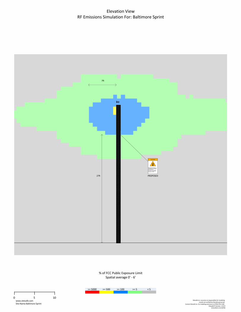
Note: In the RF Emissions Simulation diagram, all heights are reflected with respect to ground level. Emissions are calculated appropriately based on the relative height to all antennas.
The finding below detail the theoretical modeling results by Sitesafe Inc. A typical antenna installation may be installed on top of a utility pole, although a stand- alone pole may be used when it is required.
Minimum Horizontal distance General Public MPE limit = 7ft Minimum Vertical distance General Public MPE limit = 27ft

200 N. Glebe Road Suite 1000 Arlington, VA 22203-3728 703.276.1100 [email protected]
Page 3
2 Regulatory Basis 2.1 FCC Rules and Regulations
In 1996, the Federal Communication Commission (FCC) adopted regulations for the evaluating of the effects of RF emissions in 47 CFR § 1.1307 and 1.1310. The guideline from the FCC Office of Engineering and Technology is Bulletin 65 (“OET Bulletin 65”), Evaluating Compliance with FCC Guidelines for Human Exposure to Radio Frequency Electromagnetic Fields, Edition 97-01, published August 1997. Since 1996 the FCC periodically reviews these rules and regulations as per their congressional mandate.
FCC regulations define two separate tiers of exposure limits: Occupational or “Controlled environment” and General Public or “Uncontrolled environment”. The General Public limits are generally five times more conservative or restrictive than the Occupational limit. These limits apply to accessible areas where workers or the general public may be exposed to Radio Frequency (RF) electromagnetic fields.
Occupational or Controlled limits apply in situations in which persons are exposed as a consequence of their employment and where those persons exposed have been made fully aware of the potential for exposure and can exercise control over their exposure.
An area is considered a Controlled environment when access is limited to these aware personnel. Typical criteria are restricted access (i.e. locked or alarmed doors, barriers, etc.) to the areas where antennas are located coupled with proper RF warning signage. A site with Controlled environments is evaluated with Occupational limits.
All other areas are considered Uncontrolled environments. If a site has no access controls or no RF warning signage it is evaluated with General Public limits.
The theoretical modeling of the RF electromagnetic fields has been performed in accordance with OET Bulletin 65. The Maximum Permissible Exposure (MPE) limits utilized in this analysis are outlined in the following diagram:
FCC Limits for Maximum Permissible Exposure (MPE)
Plane-wave Equivalent Power Density
1000
100
10
1
0.1
0.01
0 1 10 100 1,000 10,000
Frequency (MHz)
Limits for Occupational/Controlled Exposure (MPE)
OccupationalGeneral Public
Po
wer
Den
sit
y (
mW
/cm
2)

200 N. Glebe Road Suite 1000 Arlington, VA 22203-3728 703.276.1100 [email protected]
Page 4
Frequency Range
Electric Field
Magnetic Field
Power Density
Averaging Time |E|2, |H|2 or S (minutes)
(MHz) Strength (E) (V/m)
Strength (H) (A/m)
(S) (mW/cm2)
0.3-3.0 614 1.63 (100)* 6 3.0-30 1842/f 4.89/f (900/f2)* 6 30-300 61.4 0.163 1.0 6 300-1500 -- -- f/300 6 1500- -- -- 5 6 100,000
Limits for General Population/Uncontrolled Exposure (MPE)
Frequency Range
Electric Field
Magnetic Field
Power Density
Averaging Time |E|2, |H|2 or S (minutes)
(MHz) Strength (E) Strength (S)
(V/m) (H) (A/m) (mW/cm2)
0.3-1.34 614 1.63 (100)* 301.34-30 824/f 2.19/f (180/f2)* 30 30-300 27.5 0.073 0.2 30300-1500 -- -- f/1500 301500- -- -- 1.0 30100,000
f = frequency in MHz *Plane-wave equivalent power density
2.2 OSHA Statement The General Duty clause of the OSHA Act (Section 5) outlines the occupational safety and health responsibilities of the employer and employee. The General Duty clause in Section 5 states:
(a) Each employer –
(1) shall furnish to each of his employees employment and a place of employment which are free from recognized hazards that are causing or are likely to cause death or serious physical harm to his employees;
(2) shall comply with occupational safety and health standards promulgated under this Act.
(b) Each employee shall comply with occupational safety and health standards
and all rules, regulations, and orders issued pursuant to this Act which are applicable to his own actions and conduct.
OSHA has defined Radiofrequency and Microwave Radiation safety standards for workers who may enter hazardous RF areas. Regulation Standards 29 CFR § 1910.147 identify a generic Lock Out Tag Out procedure aimed to control the unexpected energization or start up of machines when maintenance or service is being performed.

200 N. Glebe Road Suite 1000 Arlington, VA 22203-3728 703.276.1100 [email protected]
Page 5
3 Site Compliance 3.1 Site Compliance Statement
Upon evaluation of the cumulative RF emission levels from all operators at this site, Sitesafe has determined that:
This site will be compliant with the FCC rules and regulations, as described in OET Bulletin 65.
The compliance determination is based on theoretical modeling, RF signage placement recommendations, proposed antenna inventory and the level of restricted access to the antennas at the site. Any deviation from the ExteNet Systems Inc.’s proposed deployment plan could result in the site being rendered non-compliant.
3.2 Actions for Site Compliance
Based on common industry practice and our understanding of FCC and OSHA requirements, this section provides a statement of recommendations for site compliance. RF alert signage recommendations have been proposed based on theoretical analysis of MPE levels. Barriers can consist of locked doors, fencing, railing, rope, chain, paint striping or tape, combined with RF alert signage.
This site will be compliant with the FCC rules and regulations.
Sitesafe found one or more issues that led to our determination. The site will be made compliant if the following are implemented:
ExteNet Systems Inc. Proposed Antenna Location
Yellow caution sign is required to be installed below the antenna away from the view by the general public.

200 N. Glebe Road Suite 1000 Arlington, VA 22203-3728 703.276.1100 [email protected]
Page 6
4 Safety Plan and Procedures The following items are general safety recommendations that should be administered on a site by site basis as needed by the carrier.
General Maintenance Work: Any maintenance personnel required to work immediately in front of antennas and / or in areas indicated as above 100% of the Occupational MPE limits should coordinate with the wireless operators to disable transmitters during their work activities.
Training and Qualification Verification: All personnel accessing areas indicated as exceeding the General Population MPE limits should have a basic understanding of EME awareness and RF Safety procedures when working around transmitting antennas. Awareness training increases a workers understanding to potential RF exposure scenarios. Awareness can be achieved in a number of ways (e.g. videos, formal classroom lecture or internet based courses).
Physical Access Control: Access restrictions to transmitting antennas locations is the primary element in a site safety plan. Examples of access restrictions are as follows:
Locked door or gate Alarmed door Locked ladder access Restrictive Barrier at antenna (e.g. Chain link with posted RF Sign)
RF Signage: Everyone should obey all posted signs at all times. RF signs play an important role in properly warning a worker prior to entering into a potential RF Exposure area.
Assume all antennas are active: Due to the nature of telecommunications transmissions, an antenna transmits intermittently. Always assume an antenna is transmitting. Never stop in front of an antenna. If you have to pass by an antenna, move through as quickly and safely as possible thereby reducing any exposure to a minimum.
Maintain a 3 foot clearance from all antennas: There is a direct correlation between the strength of an EME field and the distance from the transmitting antenna. The further away from an antenna, the lower the corresponding EME field is.
Site RF Emissions Diagram: Section 5 of this report contains an RF Diagram that outlines various theoretical Maximum Permissible Exposure (MPE) areas at the site. The modeling is a worst case scenario assuming a duty cycle of 100% for each transmitting antenna at full power. This analysis is based on one of two access control criteria: General Public criteria means the access to the site is uncontrolled and anyone can gain access. Occupational criteria means the access is restricted and only properly trained individuals can gain access to the antenna locations.
200 N. Glebe Road Suite 1000 Arlington, VA 22203-3728 703.276.1100 [email protected]
Page 7
5 Analysis 5.1 RF Emissions Diagram
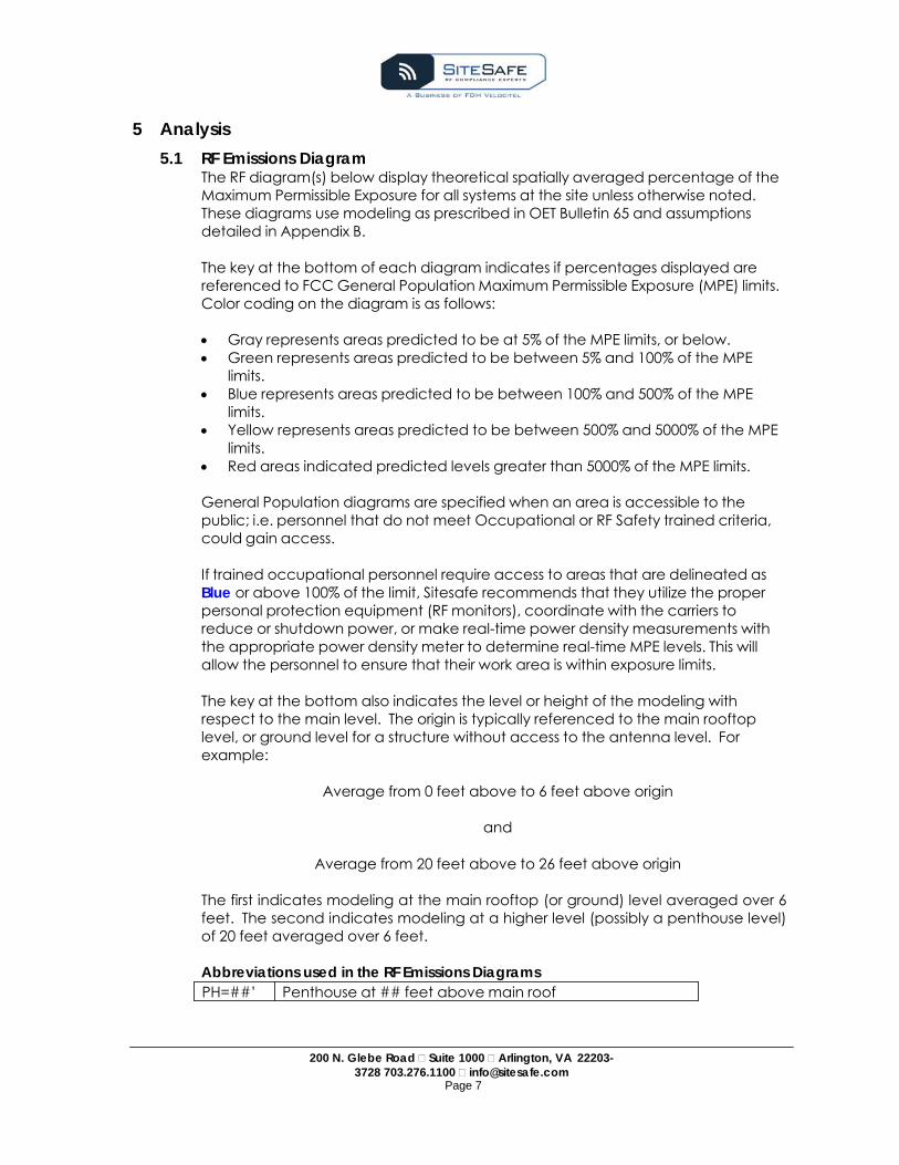
The RF diagram(s) below display theoretical spatially averaged percentage of the Maximum Permissible Exposure for all systems at the site unless otherwise noted. These diagrams use modeling as prescribed in OET Bulletin 65 and assumptions detailed in Appendix B.
The key at the bottom of each diagram indicates if percentages displayed are referenced to FCC General Population Maximum Permissible Exposure (MPE) limits. Color coding on the diagram is as follows:
Gray represents areas predicted to be at 5% of the MPE limits, or below. Green represents areas predicted to be between 5% and 100% of the MPE
limits. Blue represents areas predicted to be between 100% and 500% of the MPE
limits. Yellow represents areas predicted to be between 500% and 5000% of the MPE
limits. Red areas indicated predicted levels greater than 5000% of the MPE limits.
General Population diagrams are specified when an area is accessible to the public; i.e. personnel that do not meet Occupational or RF Safety trained criteria, could gain access.
If trained occupational personnel require access to areas that are delineated as Blue or above 100% of the limit, Sitesafe recommends that they utilize the proper personal protection equipment (RF monitors), coordinate with the carriers to reduce or shutdown power, or make real-time power density measurements with the appropriate power density meter to determine real-time MPE levels. This will allow the personnel to ensure that their work area is within exposure limits.
The key at the bottom also indicates the level or height of the modeling with respect to the main level. The origin is typically referenced to the main rooftop level, or ground level for a structure without access to the antenna level. For example:
Average from 0 feet above to 6 feet above origin
and
Average from 20 feet above to 26 feet above origin
The first indicates modeling at the main rooftop (or ground) level averaged over 6 feet. The second indicates modeling at a higher level (possibly a penthouse level) of 20 feet averaged over 6 feet.
Abbreviations used in the RF Emissions Diagrams
PH=##’ Penthouse at ## feet above main roof

www.sitesafe.com Site Name: Baltimore Sprint
Sitesafe Inc. assumes no responsiblity for modeling results not verified by Sitesafe personnel.
Contact Sitesafe Inc. for modeling assistance at (703) 276‐1100 SitesafeTC Version: 1.0.0.0
5/15/2015 2:16:24 PM
Plan View RF Emissions Simulation
1
CAUTION
Beyond This Point you are entering a controlled area where RF Emissions may exceed the FCC Occupational Exposure Limits
Proposed
% of FCC Public Exposure Limit
Spatial average 0' ‐ 6'
0 7.5 15
>= 5000 >= 500 >= 100 >= 5 < 5
N
www.sitesafe.com Site Name:Baltimore Sprint
Sitesafe Inc. assumes no responsiblity for modeling results not verified by Sitesafe personnel.
Contact Sitesafe Inc. for modeling assistance at (703) 276‐1100 SitesafeTC Version: 1.0.0.0
5/15/2015 1:53:39 PM
Elevation View RF Emissions Simulation For: Baltimore Sprint
7ft
123
CAUTION
Beyond This Point you are entering a controlled area where RF Emissions may exceed the FCC Occupational Exposure Limits
27ft PROPOSED
% of FCC Public Exposure Limit Spatial average 0' ‐ 6'
0 5 10
>= 5000 >= 500 >= 100 >= 5 < 5

6 Antenna Inventory The Antenna Inventory shows all transmitting antennas at the site. This inventory was provided by the customer, and was utilized by Sitesafe to perform theoretical modeling of RF emissions. The inventory coincides with the site diagrams in this report, identifying each antenna’s location at NE-MD-BALTIMOR-SPR - Baltimore Sprint. The antenna information collected includes the following information:
Licensee or wireless operator name Frequency or frequency band Transmitter power – Effective Radiated Power (“ERP”), or Equivalent Isotropic
Radiated Power (“EIRP”) in Watts Antenna manufacturer make, model, and gain
For other carriers at this site, the use of “Generic” as an antenna model, or “Unknown” for an operator means the information with regard to carrier, their FCC license and/or antenna information was not available nor could it be secured while on site. Equipment, antenna models and nominal transmit power were used for modeling, based on past experience with radio service providers.
200 N. Glebe Road Suite 1000 Arlington, VA 22203-3728 703.276.1100 [email protected]
Page 10

A
The fo
Ant #
No
1 DC03XC013
1 DC03XC013
1 DC03XC013
NOTE: Xreference greater th
llowing antenna
ode ID
3DC03XC122_2
3DC03XC122_2
3DC03XC122_2
X, Y and Z indicate re indicates antenna an are currently dep
a inventory was
TX Freq
(MHz)
ERP (Watts)
1900 273.5
1900 273.5
1900 273.5
elative position of thheight above the mployed.
200
provided by the
Table 3: AAntenna
Gain (dBd)
Az (Deg
9.07 50
9.07 170
9.07 290
he antenna to the omain site level unless
0 N. Glebe Road Su703.276.11
e customer and
Antenna Inven g)
Antenna
Cellmax CMM15/
0 Cellmax CMM15/
0 Cellmax CMM15/
rigin location on the otherwise indicated
uite 1000 Arlington100 [email protected]
Page 11
was utilized to c
ntory a Model A
T
M-BD-TRI/65- /12
Pa
M-BD-TRI/65- /12
Pa
M-BD-TRI/65- /12
Pa
e site, displayed in thd. ERP values provide
n, VA 22203-3728 com
create the site m
Ant Type
Len (ft)
HoHalBea
(anel 2
anel 2
anel 2
he model results diaed by the client and
model diagrams
orizontal lf Power amwidth (Deg)
Lo
X
62 73.8'
62 73.8'
62 73.8'
gram. Specifically, td used in the model
:
ocation
Y Z
116.9' 35'
116.9' 35'
116.9' 35'
the Z ling may be

200 N. Glebe Road Suite 1000 Arlington, VA 22203-3728 703.276.1100 [email protected]
Page 12
7 Engineer Certification
The professional engineer whose seal appears on the cover of this document hereby
certifies and affirms that:
I am registered as a Professional Engineer in the jurisdiction indicated in the
professional engineering stamp on the cover of this document; and
That I am an employee of Sitesafe, Inc., in Arlington, Virginia, at which place the staff
and I provide RF compliance services to clients in the wireless communications industry; and
That I am thoroughly familiar with the Rules and Regulations of the Federal
Communications Commission (FCC) as well as the regulations of the Occupational Safety
and Health Administration (OSHA), both in general and specifically as they apply to the FCC
Guidelines for Human Exposure to Radio-frequency Radiation; and
That I have thoroughly reviewed this Site Compliance Report and believe it to be true
and accurate to the best of my knowledge as assembled by and attested to by Kobi
Thompson.
May 15, 2015

200 N. Glebe Road Suite 1000 Arlington, VA 22203-3728 703.276.1100 [email protected]
Page 13
Appendix A – Statement of Limiting Conditions Sitesafe will not be responsible for matters of a legal nature that affect the site or property.
Due to the complexity of some wireless sites, Sitesafe performed this analysis and created this report utilizing best industry practices and due diligence. Sitesafe cannot be held accountable or responsible for anomalies or discrepancies due to actual site conditions (i.e., mislabeling of antennas or equipment, inaccessible cable runs, inaccessible antennas or equipment, etc.) or information or data supplied by ExteNet Systems Inc., the site manager, or their affiliates, subcontractors or assigns.
Sitesafe has provided computer generated model(s) in this Site Compliance Report to show approximate dimensions of the site, and the model is included to assist the reader of the compliance report to visualize the site area, and to provide supporting documentation for Sitesafe’s recommendations.
Sitesafe may note in the Site Compliance Report any adverse physical conditions, such as needed repairs, observed during the survey of the subject property or that Sitesafe became aware of during the normal research involved in performing this survey. Sitesafe will not be responsible for any such conditions that do exist or for any engineering or testing that might be required to discover whether such conditions exist. Because Sitesafe is not an expert in the field of mechanical engineering or building maintenance, the Site Compliance Report must not be considered a structural or physical engineering report.
Sitesafe obtained information used in this Site Compliance Report from sources that Sitesafe considers reliable and believes them to be true and correct. Sitesafe does not assume any responsibility for the accuracy of such items that were furnished by other parties. When conflicts in information occur between data provided by a second party and physical data collected by Sitesafe, the physical data will be used.

200 N. Glebe Road Suite 1000 Arlington, VA 22203-3728 703.276.1100 [email protected]
Page 14
Appendix B – Assumptions and Definitions General Model Assumptions
In this site compliance report, it is assumed that all antennas are operating at full power at all times. Software modeling was performed for all transmitting antennas located on the site. Sitesafe has further assumed a 100% duty cycle and maximum radiated power.
The site has been modeled with these assumptions to show the maximum RF energy density. Sitesafe believes this to be a worst-case analysis, based on best available data. Areas modeled to predict emissions greater than 100% of the applicable MPE level may not actually occur, but are shown as a worst-case prediction that could be realized real time. Sitesafe believes these areas to be safe for entry by occupationally trained personnel utilizing appropriate personal protective equipment (in most cases, a personal monitor).
Thus, at any time, if power density measurements were made, we believe the real- time measurements would indicate levels below those depicted in the RF emission diagram(s) in this report. By modeling in this way, Sitesafe has conservatively shown exclusion areas – areas that should not be entered without the use of a personal monitor, carriers reducing power, or performing real-time measurements to indicate real-time exposure levels.
Use of Generic Antennas
For the purposes of this report, the use of “Generic” as an antenna model, or “Unknown” for an operator means the information about a carrier, their FCC license and/or antenna information was not provided and could not be obtained while on site. In the event of unknown information, Sitesafe will use our industry specific knowledge of equipment, antenna models, and transmit power to model the site. If more specific information can be obtained for the unknown measurement criteria, Sitesafe recommends remodeling of the site utilizing the more complete and accurate data. Information about similar facilities is used when the service is identified and associated with a particular antenna. If no information is available regarding the transmitting service associated with an unidentified antenna, using the antenna manufacturer’s published data regarding the antenna’s physical characteristics makes more conservative assumptions.
Where the frequency is unknown, Sitesafe uses the closest frequency in the antenna’s range that corresponds to the highest Maximum Permissible Exposure (MPE), resulting in a conservative analysis.

200 N. Glebe Road Suite 1000 Arlington, VA 22203-3728 703.276.1100 [email protected]
Page 15
Definitions
5% Rule – The rules adopted by the FCC specify that, in general, at multiple transmitter sites actions necessary to bring the area into compliance with the guidelines are the shared responsibility of all licensees whose transmitters produce field strengths or power density levels at the area in question in excess of 5% of the exposure limits. In other words, any wireless operator that contributes 5% or greater of the MPE limit in an area that is identified to be greater than 100% of the MPE limit is responsible taking corrective actions to bring the site into compliance.
Compliance – The determination of whether a site is safe or not with regards to Human Exposure to Radio Frequency Radiation from transmitting antennas.
Decibel (dB) – A unit for measuring power or strength of a signal.
Duty Cycle – The percent of pulse duration to the pulse period of a periodic pulse train. Also, may be a measure of the temporal transmission characteristic of an intermittently transmitting RF source such as a paging antenna by dividing average transmission duration by the average period for transmission. A duty cycle of 100% corresponds to continuous operation.
Effective (or Equivalent) Isotropic Radiated Power (EIRP) – The product of the power supplied to the antenna and the antenna gain in a given direction relative to an isotropic antenna.
Effective Radiated Power (ERP) – In a given direction, the relative gain of a transmitting antenna with respect to the maximum directivity of a half wave dipole multiplied by the net power accepted by the antenna from the connecting transmitter.
Gain (of an antenna) – The ratio of the maximum intensity in a given direction to the maximum radiation in the same direction from an isotropic radiator. Gain is a measure of the relative efficiency of a directional antennas as compared to an omni directional antenna.
General Population/Uncontrolled Environment – Defined by the FCC, as an area where RFR exposure may occur to persons who are unaware of the potential for exposure and who have no control of their exposure. General Population is also referenced as General Public.
Generic Antenna – For the purposes of this report, the use of “Generic” as an antenna model means the antenna information was not provided and could not be obtained while on site. In the event of unknown information, Sitesafe will use our industry specific knowledge of antenna models to select a worst case scenario antenna to model the site.
Isotropic Antenna – An antenna that is completely non-directional. In other words, an antenna that radiates energy equally in all directions.
Maximum Measurement – This measurement represents the single largest measurement recorded when performing a spatial average measurement.

200 N. Glebe Road Suite 1000 Arlington, VA 22203-3728 703.276.1100 [email protected]
Page 16
Maximum Permissible Exposure (MPE) – The rms and peak electric and magnetic field strength, their squares, or the plane-wave equivalent power densities associated with these fields to which a person may be exposed without harmful effect and with acceptable safety factor.
Occupational/Controlled Environment – Defined by the FCC, as an area where Radio Frequency Radiation (RFR) exposure may occur to persons who are aware of the potential for exposure as a condition of employment or specific activity and can exercise control over their exposure.
OET Bulletin 65 – Technical guideline developed by the FCC’s Office of Engineering and Technology to determine the impact of Radio Frequency radiation on Humans. The guideline was published in August 1997.
OSHA (Occupational Safety and Health Administration) – Under the Occupational Safety and Health Act of 1970, employers are responsible for providing a safe and healthy workplace for their employees. OSHA's role is to promote the safety and health of America's working men and women by setting and enforcing standards; providing training, outreach and education; establishing partnerships; and encouraging continual process improvement in workplace safety and health. For more information, visit www.osha.gov.
Radio Frequency Radiation – Electromagnetic waves that are propagated from antennas through space.
Spatial Average Measurement – A technique used to average a minimum of ten (10) measurements taken in a ten (10) second interval from zero (0) to six (6) feet. This measurement is intended to model the average energy an average sized human body will absorb while present in an electromagnetic field of energy.
Transmitter Power Output (TPO) – The radio frequency output power of a transmitter’s final radio frequency stage as measured at the output terminal while connected to a load.

200 N. Glebe Road Suite 1000 Arlington, VA 22203-3728 703.276.1100 [email protected]
Page 17
Appendix C – Rules & Regulations Explanation of Applicable Rules and Regulations
The FCC has set forth guidelines in OET Bulletin 65 for human exposure to radio frequency electromagnetic fields. Specific regulations regarding this topic are listed in Part 1, Subpart I, of Title 47 in the Code of Federal Regulations. Currently, there are two different levels of MPE - General Public MPE and Occupational MPE. An individual classified as Occupational can be defined as an individual who has received appropriate RF training and meets the conditions outlined below. General Public is defined as anyone who does not meet the conditions of being Occupational. FCC and OSHA Rules and Regulations define compliance in terms of total exposure to total RF energy, regardless of location of or proximity to the sources of energy.
It is the responsibility of all licensees to ensure these guidelines are maintained at all times. It is the ongoing responsibility of all licensees composing the site to maintain ongoing compliance with FCC rules and regulations. Individual licensees that contribute less than 5% MPE to any total area out of compliance are not responsible for corrective actions.
OSHA has adopted and enforces the FCC’s exposure guidelines. A building owner or site manager can use this report as part of an overall RF Health and Safety Policy. It is important for building owners/site managers to identify areas in excess of the General Population MPE and ensure that only persons qualified as Occupational are granted access to those areas.
Occupational Environment Explained
The FCC definition of Occupational exposure limits apply to persons who:
are exposed to RF energy as a consequence of their employment; have been made aware of the possibility of exposure; and can exercise control over their exposure.
OSHA guidelines go further to state that persons must complete RF Safety Awareness training and must be trained in the use of appropriate personal protective equipment.
In order to consider this site an Occupational Environment, the site must be controlled to prevent access by any individuals classified as the General Public. Compliance is also maintained when any non-occupational individuals (the General Public) are prevented from accessing areas indicated as Red or Yellow in the attached RF Emissions diagram. In addition, a person must be aware of the RF environment into which they are entering. This can be accomplished by an RF Safety Awareness class, and by appropriate written documentation such as this Site Compliance Report.
All ExteNet Systems Inc. employees who require access to this site must complete RF Safety Awareness training and must be trained in the use of appropriate personal protective equipment.

App
endix D – GThe folloaccessiare nottypical
1. All indexcess successtrained
2. All indobey a
3. The sadditio
add rem cha
4. Post tpoint(s)DiagrambeyondFCC. Th
5. Ensuraccess
6. For a can be
GraThis
GrePub
200 N
General Saowing are geible areas in specific to t site manage
dividuals neeof General Psfully comple in the use of
dividuals neell posted pla
ite should ben of any ant
ding new anmoving of anyanges in the
the appropr and other lo
ms in Append posted signhe signs belo
re that the sit to the gene
General Pub interpreted
ay represents level is safe
een represenblic MPE limits
N. Glebe Road 3728 703.276
afety Recoeneral recom excess of 10this site. Thesement, build
eding accesPublic MPE) sete proper Rf appropriat
eding accesacards and si
e routinely inennas or up
tennas that y existing anradiating po
iate NOTICEocations as rdix B, to info
ns there mayw are exam
te door remaeral public if d
blic environm in the follow
s area at bel for a worker
nts areas pres. This level is
Suite 1000 A6.1100 info@si
Page 18
ommendatmmendation00% General se are safetying manage
ss to the maishould wear F Safety Awae personal p
ss to the maiigns.
spected andon any chan
may have btennas
ower or numb
, CAUTION, orequired. No
orm everyoney be levels inples of signs
ains locked (deemed as p
ment the fouwing manner
low 5% of ther to be in at adicted to bes safe for a w
Arlington, VA 22itesafe.com
tions ns appropria Public MPE.
y recommenement, and o
n site (or the a personal Rareness train
protective eq
n site should
d this or similnges to the R
been located
ber of RF em
or WARNINGote: Please re who has ac excess of th meeting FC
(or appropriapolicy by the
ur color levelr:
e General Puany time. e between 5worker to be
2203-
ate for any sit These reco
ndations appother tenant
e area indicaRF Exposure mning, and haquipment.
d be instructe
ar report upRF environme
d on the site
mitters
G sign at the mrefer to RF Exccess to this
he limits presCC guidelines
ately controe building/sit
s identified in
ublic MPE lim
5% and 100% in at any tim
te with mmendatio
propriate for t operations.
ated to be inmonitor, ve and be
ed to read a
dated with tent including
main site accxposure site that cribed by ths.
lled) to denyte owner.
n this analysi
mits or below
% of the Geneme.
ns
n
nd
the g:
cess
he
y
is
w.
eral

200 N. Glebe Road Suite 1000 Arlington, VA 22203-3728 703.276.1100 [email protected]
Page 19
Blue represents areas predicted to be between 100% and 500% of the General Public MPE limits. This level is safe for a worker to be in at any time.
Yellow represents areas predicted to be between 500% and 5000% of the General Public MPE limits. This level is safe for a worker to be in.
Red areas indicated predicted levels greater than 5000% of the General Public MPE limits. This level is not safe for the General Public to be in.
7. For an Occupational environment the four color levels identified in this analysis can be interpreted in the following manner:
Areas indicated as Gray are at 5% of the Occupational MPE limits or below.
This level is safe for a worker to be in at any time. Green represents areas predicted to be between 5% and 20% of the
Occupational MPE limits. This level is safe for a worker to be in at any time. Yellow represents areas predicted to be between 20% and 100% of the
Occupational MPE limits. Only individuals that have been properly trained in RF Health and Safety should be allowed to work in this area. This is not an area that is suitable for the General Public to be in.
Red areas indicated predicted levels greater than 100% of the Occupational MPE limits. This level is not safe for the Occupational worker to be in for prolonged periods of time. Special procedures must be adhered to such as lock out tag out procedures to minimize the workers exposure to EME.
8. Use of a Personal Protective Monitor: When working around antennas, Sitesafe strong recommends the use of a Personal Protective Monitor (PPM). Wearing a PPM will properly forewarn the individual prior to entering an RF exposure area.
Keep a copy of this report available for all persons who must access the site. They should read this report and be aware of the potential hazards with regards to RF and MPE limits.
Additional Information
Additional RF information is available by visiting both www.Sitesafe.com and www.fcc.gov/oet/rfsafety. OSHA has additional information available at: http://www.osha-slc.gov/SLTC/radiofrequencyradiation.