decnet digital network architecture
TRANSCRIPT
Order No. AA-K181 A-TK
DECnet DIGITAL Network Architecture
Network Management Functional Specification
Version 2.0.0

DECnet DIGITAL Network Architecture
(Phase Ill)
Network Management Functional Specification
Order No. AA-K181 A-TK Version 2.0.0
October 1980
This document describes the functions, structures, protocols, algorithms, and operation of the DIGITAL Network Architec- ture Network Management modules. It is a model for DECnet implementations of Network Management software. Network Management provides control and observation of DECnet net- work functions to users and programs.
To order additional copies of this document, contact your local Digital Equipment Corporation Sales Office.
I
digital equipment corporation maynard, massachusetts

First Printing, October 1980
This material may be copied, in whole or in part, provided that the copyright notice below in included in each copy along with an acknowledgment that the copy describes protocols, algorithms, and structures developed by Digital Equipment Corporation.
This material may be changed without notice by Digital Equipment Corporation, and Digital Equipment Corporation is not responsible for any errors which may appear herein.
Copyright C 1980 by Digital Equipment Corporation 0
The postage-prepaid READER'S COMMENTS form on the last page of this document requests the user's critical evaluation to assist us in pre- paring future documentation.
The following are trademarks of Digital Equipment Corporation:
DIGITAL DEC PDP DECUS UNIBUS COMPUTER LABS COMTEX DDT DECCOMM ASSIST-11 VAX DECnet DATATRIEVE
D E C 8 y ~ t ~ - 1 0 DECtape DIBOL EDUSYSTEM FLIP CHIP FOCAL INDAC LAB-8 DECSY STEM-20 RTS-8 VMS IAS TRAX
MASSBUS OMNIBUS OS/8 PHA RSTS Rsx TYPESET-8 TYPESET-11 TMS-11 ITPS-10 SBI PDT

CONTENTS
INTRODUCTION FUNCTIONAL DESCRIPTION
Design Scope Relationship to DIGITAL Network Architecture Functional Organization within DIGITAL Network Architecture
NETWORK CONTROL PROGRAM (NCP) Network Control Program Functions Changing Parameters Gathering Information Down-line Loading Up-line Dumping Testing Line and Network Zeroing Counters Network Control Program Operation Specifying the Executor Program Invocation, Termination, and Prompting Privileged Commands Input Formats Output Characteristics Status and Error Messages Network Control Program Commands SET and DEFINE Commands SET and DEFINE EXECUTOR NODE destination-node SET and DEFINE KNOWN Entity Commands SET and DEFINE LINE Commands SET and DEFINE LOGGING Commands SET and DEFINE NODE Commands CLEAR and PURGE Commands CLEAR and PURGE EXECUTOR NODE Commands CLEAR and PURGE KNOWN Entity Commands CLEAR and PURGE LINE Commands CLEAR and PURGE LOGGING Commands CLEAR and PURGE NODE Commands TRIGGER Command LOAD Command LOAD NODE Command LOAD VIA Command DUMP Command LOOP Command LOOP LINE Command LOOP NODE Command SHOW QUEUE Command SHOW and LIST Commands Information Type Display Format Counter Display Format Tabular and Sentence Formats Restrictions and Rules on Returns ZERO Command EXIT Command
NETWORK MANAGEMENT LAYER
Page
iii

CONTENTS (C0nt.I
Page
Network Management Layer Modules Network Management Access Routines and Listener Local Network Management Functions Line Watcher Line Service Functions States and Substates Priority Control Line State Algorithms Line Handling Functions Event Logger Event Logger Components Suggested Formats for Logging Data Network Management Layer Operation Down-line Load Operation Up-line Dump Operation Trigger Bootstrap Operation Loop Test Operation Node Level Testing Data Link Testing Change Parameter Operation Read Information Operation Zero Counters Operation NICE Logical Link Handling Algorithm for Accepting Version Numbers Return Code Handling Network Management Layer Messages NICE Function Codes Message and Data Type Format Notation Request Down-line Load Message Format Request Up-line Dump Message Format Trigger Bootstrap Message Format Test Message Format Change Parameter Message Format Read Information Message Format Zero Counters Message Format NICE System Specific Message Format NICE Response Message Format NICE Connect and Accept Data Formats Event Message Binary Data Format
APPLICATION LAYER NETWORK MANAGEMENT FUNCTIONS Loopback Mirror Modules Loopback Mirror Operation Logical Loopback Message Connect Accept Data Format Command Message Format Response Message
APPENDIX A NETWORK MANAGEMENT ENTITIES, PARAMETERS AND COUNTERS: FORMATS AND DATA BLOCKS
A. 1 LINE Entity A. I. 1 Line Parameters A. 1.2 Line Counters A. 2 LOGGING Entity A. 3 NODE Entity~ A.3.1 Node Parameters A.3.2 Node Counters APPENDIX B MEMORY IMAGE FORMATS

CONTENTS (Cont . )
Page
APPENDIX C MEMORY IMAGE FILE CONTENTS APPENDIX D NICE RETURN CODES WITH EXPLANATIONS APPENDIX E NCP COMMAND STATUS AND ERROR MESSAGES APPENDIX F EVENTS F. I Event Class Definitions F. 2 Event Definitions F. 3 Event Parameter Definitions APPENDIX G JULIAN HALF-DAY ALGORITHMS APPENDIX H DMC DEVICE COUNTERS APPENDIX I NCP COMMANDS SUPPORTING EACH NETWORK MANAGEMENT
INTERFACE
GLOSSARY
FIGURE 1 2
TABLE 1 2 3 4
FIGURES
Network Management Relation to DNA Network Management Layer Modules and Interfaces in a Single Node Event Logging Architectural Model Down-line Load File Access Operation Down-line Load Request Operation Examples of Node Level Testing Using a Loopback Node Name with and without the Loopback Mirror Examples of Node Level Logical Link Loopback Test with and without the Loopback Mirror Physical Link Loopback Tests and Command Sequences Effecting Them
TABLES
NCP Commands Network Management Line States Line State Transitions Line Service States, Substates and Functions and Their Relationship to Line States DECnet Line Devices Line Parameters Line Counters Logging Parameters Node Parameters Node Counters Event Classes Events
10 5 106 Ill 113


1.0 INTRODUCTION
This document describes the structure, functions, operation, and protocols of Network Management. Network Management is that part of the DIGITAL Network Architecture that models the software that enables operators and programs to plan, control, and maintain the operation of centralized or distributed DECnet networks. DIGITAL Network Architecture (DNA) is the model on which DECnet network software implementations are based. Network software is the family of software modules, data bases, hardware components, and facilities used to tie DIGITAL systems together in a network for resource sharing, distributed computation, or remote system communication.
DNA is a layered structure. ~odules in each layer perform distinct functions. Modules within the same layer (either in the same or different nodes) communicate using specific protocols. The protocols specified in this document are the Network Information and Control Exchange (NICE) protocol, the Loopback Mirror protocol, and the Event Receiver protocol.
Modules in different layers interface using subroutine calls or a similar system-dependent method. In this document, interface communications between layers are referred to as calls or requests because this is the most convenient way of describing them functionally. An implementation need not be written as calls to subroutines. Interfaces to other DNA layers are not specified in detail, however, Appendix I describes which Network Management user commands (Network Control Program) support each DNA interface.
In this document network nodes are described by function as executor, command, host, and target. The executor is an active network node connected to one end of a line being used for a load, dump, or line loop test and is the node that executes requests. The command node is the node in which the Network Management request originates. The host is a node that provides a higher level service such as a file system. The target is a node that is to receive a load, loop back a test message, or generate a dump. Executor, command, and host nodes may be three different nodes, all the same node, or any combination of two nodes. A glossary at the end of this document defines many Network Management terms.
This document describes commands that can be standardized across different DECnet implementations. An implementation may use only a subset of the commands described herein. Moreover, commands and functions specific to one particular operating system are not described.
This document specifies the functional requirements of Network Management. Both algorithms and operational descriptions support this specification. However, an implementation is not required to use the same algorithms. It is only required to have the functions (or a subset of them) specified.

This is one of a series of functional specifications for the DIGITAL Network Architecture, Phase 111. This document assumes that the reader is familiar with computer communications and DECnet. The primary audience for this specification consists of implementers of DECnet systems, but it may be of interest to anyone wishing to know details of DECnet structure. The other DNA Phase I11 functional specifications are:
DNA Data Access Protocol (DAP) Functional Specification, Version 5.6.0, Order No. AA-K177A-TK
DNA Diaital Data Communications Messaae Protocol {DDCMPI - - - - - . - , - - - - - - ~unctional Specification, ~ersion' 4 . . , 1 0 Order No. AA-K175A-TK
DNA Maintenance Operations Protocol (MOP) Functional Specification, Version 2.1.0, Order No. A- - -
DNA Network Services (NSP) Functional Specification, Version 3.2.0, Order No. AA-K176A-TK
DNA Transport Functional Specification, Version 1.3.0, Order No. AA-K180A-TK
DNA Session Control Functional Specification, Version 1.0.0, Order No. AA-K182A - TK
The DNA General Description (Order No. AA-K179A-TK) provides an overview of the network architecture and an introduction to each of the functional specifications.

2.0 FUNCTIONAL DESCRIPTION
Network Management enables operators and programs to control and monitor network operation. Network Management helps the manager of a network to plan its evolution. Network Management also facilitates detection, isolation, and resolution of conditions that impede effective network use.
Network Management provides user commands and capability to user programs for performing the following control functions:
1. Loading remote systems. A system in one node can down-line load a system in another node in the same network.
2. Configuring resources. A system manager can change the network configuration and modify message traffic patterns.
3. Setting parameters. Line, node, and logging parameters (for example, node names) can be set and changed.
4. Initiating and terminating network functions. A system manager or operator can turn the network on or off and perform loopback tests and other functions.
Network Management also enables the user to monitor network functions, configurations, and states, as follows:
1. Dumping remote systems. A system in one node can up-line dump a system to another node in the same network.
2. Examining configuration status. Information about lines and nodes can be obtained. For example, an operator can display
, the states of lines and nodes or the names of adjacent nodes.
3. Examining parameters. Line and node parameters (for example, timer settings, line type, or node names) can be read.
4. Examining the status of network operations. An operator can monitor network operations. For example, the operator can find out what operations are in progress and whether any have failed.
5. Examining performance variables. A system manager can examine the contents of counters in lower DNA layers to measure network performance. In addition, Network Management's Event Logger provides automatic logging of significant network events.
Besides controlling and monitoring the day-to-day operation of the network, the functions listed above work to collect information for future planning. These functions furnish basic operations (primitives) for detecting failures, isolating problems, and repairing and restoring a network.
2.1 Design Scope
Network Management functions satisfy the following design requirements:
1. Common interfaces. Common interfaces are provided to operators and programs, regardless of network topology or configuration, as much as possible without impacting the

quality of existing products. There is a compromise between the compatibility of network commands across heterogeneous systems and the compatibility within a system between network and other local system commands.
2. Subsetability. Nodes are able to support a subset of Network Management components or functions.
3. Ease of use. Invoking and understanding Network Management functions are easy for the operator or user programmer.
4. Network efficiency. Network Management is both processing and memory efficient. It is line efficient where this does not conflict with other goals.
5. Extensibility. There is accommodation for future, additional management functions, leaving earlier functions as a compatible subset. This specification serves as a basis for building more sophisticated network management programs.
6. Heterogeneity. Network Management operates across a mixture of network node types, communication lines, topologies, and among different versions of Network Management software.
7. Robustness. The effects of errors such as operator input errors, protocol errors, and hardware errors are minimized.
8. Security. Network Management supports the existing security mechanisms in the DIGITAL Network Architecture (for example, the access control mechanism of the Session Control layer).
9. Simplicity. Complex algorithms and data bases are avoided. Functions provided elsewhere in the architecture are not duplicated.
1 0 . Support of diverse management policies. Network Management covers a range between completely centralized and fully distributed management.
The following are not within the scope of Version 2 . 0 . 0 of Network Management :
1. Accounting. This specification does not provide for the recording of usage data that would be used to keep track of individual accounts for purposes of reporting on or charging users.
2. Automation. This specification does not provide for automatic execution of complex algorithms that handle network repair or reconfiguration. More automation can be expected in future revisions of this specification.
3. Protection against malicious use. There is no foolproof protection against malicious use or gross errors by operators or programs.
4. Upward compatibility of user interfaces. The interfaces to the user layer are not necessarily frozen with this version. Observable data may change with the next version. Because of this, a function such as node-up keyed to a spooler in an implementation would not be wise.

2.2 Relationship to DIGITAL Network Architecture
DIGITAL Network Architecture (DNA), the model upon which DECnet implementations are based, outlines several functional layers, each with its own specific modules, protocols, and interfaces to adjacent layers. Network Management modules reside in the three highest layers.
The general design of DNA is as follows in order from the highest to the lowest layer:
The User layer. The User layer is the highest layer. It supports user services and programs. The Network Control Program (NCP) resides in this layer.
The Network Management layer. The Network Management layer is the only one that has direct access to each lower layer for control purposes. Modules in this layer provide user control over, and access to, network parameters and counters. Network Management modules also perform up-line dumping, down-line loading, and testing functions.
The Network Application layer. Modules in the Network Application layer support 1/0 device and file access functions. The Network Management module within this layer is the Loopback Mirror, providing logical link loopback testing.
The Session Control layer. The Session Control layer manages the system-dependent aspects of logical link communication.
The Network Services layer. The Network Services layer controls the creation, maintenance, and destruction of logical links, using the Network Services Protocol and modules.
The Transport layer. Modules in the Transport layer route messages between source and destination nodes.
The Data Link layer. The Data Link layer manages the communications over a physical link, using a data link protocol, for example, the Digital Data Communications Message Protocol (DDCMP) . The Physical Link layer. The Physical Link layer provides the hardware interfaces (such as EIA RS-232-C or CCITT V . 2 4 ) to specific system devices.
Figure 1 shows the relationship of the Network Management layer to the other DNA layers.

U w Modules L User Layer
- - - - - - - - - - - - - - - - - - - - - - - - - - - Neiwoi k Maiidqemum Modules Ne w o r k
Managrmenr Laver - - - - - - - - - Network App18cdtion Modules
Network Application Laver
I - - - - - - - - - - - - - - - . - ----- . - - I I
Session Control Modules
Session Control L w r r
t- ?^elwork Services Modules
I I
Transport Layer
- - - - - - - - - - - - Dati* Link Modules
Data Link Laver
Physical Link Modules Le Physical Link Layer
Horizontal arrows %how direct access foi control anil examination ot parameters. counters, etc Vet tical and curved arrows show inte~face~ between layers lor normal user operations such as file access, down line load up line dump. end l o end looping, and logical link urge
Figure 1 Network Management Relation to DNA
2.3 Functional Organization within DIGITAL Network Architecture
The functional components of Network Management are as follows:
User layer components
Network Control Program (NCP). The Network Control Program enables the operator to control and observe the network from a terminal. Section 3 specifies NCP.
Network Management layer components
Section 4 specifies the Network Management layer components and their operation. Figure 2 shows the relationship of Network Management layer modules in a single node.
Network Management Access Routines. These routines provide user programs and NCP with generic Network Management functions, and either convert them to Network Information and Control Exchange (NICE) protocol messages or pass them on to the Local Network Management Function.

Network Management Listener. The Network Management Listener receives Network Management commands from the Network Management level of remote nodes, via the NICE protocol. In some implementations it also receives commands from the local Network Management Access Routines via the NICE protocol. It passes these requests to the Local Network Management Function.
Local Network Management Functions. These take function requests from the Network Management Listener and the Network Management Access Routines and convert them to system dependent calls. They also provide interfaces to lower level modules directly for control purposes.
Line Watcher. The Line Watcher is a module in a node that can sense service requests on a line from a physically adjacent node. It controls automatically-sensed down-line load or up-line dump requests.
Line Service Functions. These provide the Line Watcher and the Local Network Management Functions with line services needed for service functions that require a direct interface to the data link layer (line level testing, down-line loading, up-line dumping, triggering a remote system's bootstrap loader and setting the line state). The Line Service module maintains internal states as well as line substates.
Event Logger. The Event Logger provides the capability of logging significant events for operator intervention or future reference. The process concerned with the event (for example, the Transport module) provides the data to the Event Logger, which can then record it.
Network Application Layer Components
Loopback Mirror. Access and service routines communicate using the Logical Loopback Protocol to provide node level loopback on logical links. Section 5 describes this Network Application layer component.
Object Types
The Network Management architecture requires three separate object types. Each has a unique object type number.
Loopback Mirror
The object types and numbers are:
TYPe
Network Management Listener
Object Type Number
19
Event Receiver 26

FI Fl Program
Watcher '7 Network Management
Management - - - -commands Access Routines from other
nodes
I Local Network Manawment Funct~ons
I I Events to
Lane Serv~ce Functions
Serv~ce Interface to Data Link Layer (down4ine load, upline dump, line tests, line state change)
Control over lower level functions (examine l~ne state, turn on NSP, etc.1
other nodes *- --- - - Events from other nodes
Event Lcqger
&stem.dependent calls io applicat~on layer and local operating system functims (file access, logical link loopback, timer setting, etc.)
Control interface to read went queues
LEGEND:
NCP - Network Control Program 1 - Vertical arrowheads indicate interfaces for function rwuests NICE - Network Information and
Control Exchange + - Hor~zontal arrowheads indicate control interfaces
Figure 2 Network Management Layer Modules and I n t e r f a c e s i n a S i n g l e Node
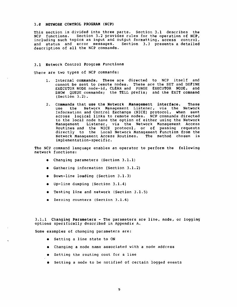
3.0 NETWORK CONTROL PROGRAM (NCP)
This section is divided into three parts. Section 3.1 describes the NCP functions. Section 3.2 provides rules for the operation of NCP, including such topics as input and output formatting, access controlw and status and error messages. Section 3.3 presents a detailed description of all the NCP commands.
3.1 Network Control Program Functions
There are two types of NCP commands:
1. Internal commands. These are directed to NCP itself and cannot be sent to remote nodes. These are the SET and DEFINE EXECUTOR NODE node-id, CLEAR and PURGE EXECUTOR NODE, and SHOW QUEUE commands; the TELL prefix; and the EXIT command (Section 3.2).
Commands that use the Network Management interface. These use the Network Management Listener, via the Network Information and Control Exchange (NICE) protocol, when sent across logical links to remote nodes. NCP commands directed to the local node have the option of either using the Network Management Listener, via the Network Management Access Routines and the NICE protocolw or of passing requests directly to the Local Network Management Function from the Network Management Access Routines. The method chosen is implementation-specific.
The NCP command language enables an operator to perform the following network functions:
Changing parameters (Section 3.1.1)
Gathering information (Section 3.1.2)
Down-line loading (Section 3.1.3)
Up-line dumping (Section 3.1.4)
Testing line and network (Section 3.1.5)
Z e r o i n g c o u n t e r s ( S e c t i o n 3.1.6)
3.1.1 Changing Parameters - The parameters are linew node, or logging options specifically described in Appendix A.
Some examples of changing parameters are:
Setting a line state to ON
Changing a node name associated with a node address
Setting the routing cost for a line
Setting a node to be notified of certain logged events

parameters may be set either as dynamic values in volatile memory using the SET command or as permanent values in a mass-storage default data base using the DEFINE command. The volatile data base is lost when the node shuts down; the permanent data base remains from one system initialization to the next. Parameters can be either status, such as line state, or characteristics that are determined by SET, DEFINEI CLEARI and PURGE commands. Characteristics are static in the sense that once set, either at system generation time or by an operator, they remain constant until cleared or reset. status consists of dynamic information (such as line state) that changes automatically when functions are performed.
permanent values take effect whenever the permanent data base is re-read. The timing of the values' taking effect is implementation-dependent. Volatile values take effect immediately.
Setting line states does not change line ownership, which is Transport or its equivalent. Line states can be setI however, to control the use of the line by its owner. To Transport, the line is either OFF or ON. To Network Management, a line can also be in a SERVICE state, a state which precludes normal traffic, and which temporarily prevents Transport from using the line. The SERVICE state is used for loading, dumping, and line testing. The ON and SERVICE states have various substates that inform the operator what function the line is performing. When states are displayedI the substates are indicated as a tag on the end of the operator-requested state.
3.1.2 Gathering Information - The information gathered includes characteristics, status, and counters associated with the line, loggingI and node entities (detailed in Appendix A). Examples of gathering information are:
Displaying the state of a line
Reading and then zeroing line counters
Displaying characteristics of all reachable nodes
0 Showing the status of all commands in progress at a node
Characteristics and status are described in Section 3.1.1.
Counters are error and performance statistics such as messages sent and received, time last zeroed, and maximum number of logical links in use.
3.1.3 Down-line Loading - Down-line loading is the process of transferring a memory image from a file to a target system's memory. This requires that the executor, the node executing the command, have direct access to the line to the target. The file may be located at another remote node, in which case the executor uses its system-specific remote file access procedures. The executor supports or has access to a data base of defaults for a load request. Section 4.2.1 describes the down-line load operation in the Network Management layer.
3.1.4 Up-line Dumping-Up-line dumping is the process of transferring the dump of a memory image from a target system to a destination file. Section 4 . 2 . 2 describes the up-line dump operation.

3.1.5 Testing Line and Network - Testing line and network can be accomplished by message looping at both the line and node levels. Testing requires receiving a transmitted message over a particular path that is looped back to the local node by either hardware or software.
Node level testing uses logical links and normal line usage. The lines involved are in the ON stateI and the Session ControlI Network Servicesr and Transport layers are used.
During line level testing! the line being tested is in the SERVICE state; normal usage is precluded. Network Management accesses the Data Link layer directly, bypassing intermediate layers. Section 4 . 2 . 4 describes line and network testing.
3.1.6 Zeroing Counters - Using NCPr an operator can set line and node counters to zero.
3.2 Network Control Program Operation
This section describes general rules concerning the operation of NCP.
The SETI DEFINEr CLEARr and PURGE commands must successfully act on either all parameters entered or on none of them. One parameter per command is all that can be expected to take effect on any systemI although a system may allow some parameters to be grouped on the same command.
3.2.1 Specifying the Executor - Since a command does not have to be executed at the node where it is typedI the operator must be able to designate on what node the command is to be processed. The operator has two options for controlling this:
1. Specifying a default executor for a set of commands
2. Naming the executor with the commad
At NCP start-up timeI the default executor is the node on which NCP is r u n n i n g o r t h e node t h a t was p r e v i o u s l y defined w i t h t h e DEFINE EXECUTOR NODE command. The default executor is changed using the SET, DEFINEI CLEARI or PURGE EXECUTOR NODE commands (see Sections 3.3.1.2 and 3.3.2.1).
With any commandI the operator can override the default executor by specifying which node is to execute the command. This is accomplished by entering "TELL node-identification" as a prefix to the command. The specified node identification applies only to the one command and does not affect the default executor or any subsequent commands.

3 . 2 . 2 Program Invocation, TerminationI and Prompting - The way NCP is invoked or terminated is system-dependent. If a name is used for the program, it must be "NCP." The EXIT command terminates NCP.
The following rules apply to the initial NCP prompt:
For an NCP that accepts only a single outstanding commandI the prompt is always the same:
For an NCP that accepts several outstanding commands where it is obvious that NCP is prompting, the prompt is:
For the multiple-outstanding-command case where it is not obvious that NCP is prompting, the prompt is:
In any caseI n is the command's request numberI which will identify the output for the command.
An implementation that cannot integrate the request number with the promptI can display the request number when the command is accepted.
3 . 2 . 3 Privileged Commands - Network and system planners must determine which commands should be limited to privileged users. The exact determination of privilege is an implementation-dependent function. Privilege is generally determined in a system-specific way according to the privileges of the local user or the access control provided at logical link connection time.
3 . 2 . 4 Input Formats - Command input is in the form of arguments delimited by tabs or blanks. Either a single or multiple tab or blank may be used to delimit arguments.
Null command lines. Null command lines will result in a command prompt being re-issued.
Node identification and access control. Nodes are identified by address or name. The primary identification is the address (a Session Control requirement). The keyword EXECUTOR can be substituted for NODE executor-node-identification. If a node identification represents a node to be connected to, access control information may be necessary or desired. If soI the access control follows the node identification, the maximum length of each field being 39 bytes. Specific systems may limit the amount of access control information they will accept. The format is:
LOOP NODE SET EXECUTOR node-id [USER user-id] [PASSWORD password] [ACCOUNT account1 { TELL
where:
LOOP NODE node-id Is an NCP command used to initiate a node loopback test (Section 3 . 3 . 6 . 2 ) . The access control applies only to the command.

SET EXECUTOR NODE node-id Is an NCP command used to set the node identification and access control for the default executor node (Section 3.3.1.1). The access control prevails until changed by another SET EXECUTOR command or a TELL or LOOP NODE command.
TELL node-id
[USER user-id]
Is an NCP command prefix used to pass one command and access control information to a specific node. The access control applies only to that one command.
Is access control information that provides the identification of the user.
[PASSWORD password] Is access control information furnishing a password.
(ACCOUNT account] Is access control information supplying an account identification.
For example:
TELL BOSS USER C 2 1 1 ~ 1 3 PASSWORD secret ACCOUNT xaz CLEAR KNOWN LINES
SET EXECUTOR NODE 97 ACCOUNT :.:Yz
String input. String input (every argument that is not a node name, keyword or number) is defined by the executor node and the length limitations of the NICE protocol. For consistency from one implementation to another, the following rules apply to NCP's parsing algorithm for these types of arguments:
Implementations will provide both a transparent and a non-transparent technique for specifying these arguments.
The transparent technique will act on any string of characters enclosed in quotation marks ("XXXXX") . A quote within the string will be indicated by a double quotation mark ("XXX""XX") .
0 The non-transparent technique will act on any string of characters that does not contain blanks or tabs. An exception to this occurs where it is possible to recognize syntactically that blanks or tabs are not intended as delimiters.
Keywords. Implementations must accept keywords in their entirety. However, the user may abbreviate keywords when typing them in. The minimum abbreviation is system-specific.
The command formats specified in this document are to be the formats used for NCP input. They may be modified only in the sense that unsupported commands or options may be left out. It is permissible to prefix a command with an identifier such as OPR NCP. However, this prefix should not affect the remainder of the command syntax or semantics. Optional system-specific guide words such as TO or FOR can be added to NCP commands if they do not interfere with defined key words.
The NCP command language does not use a question mark as a syntactic or semantic element: The question mark is left available for use according to operating system conventions.
An implementation may recognize locally defined names for lines or accept other non-standard line identifications as string inputs.

3.2.5 Output Characteristcs - The output format specified in this document is to be considered the basic pattern for all NCP output. Implementations may differ as long as common information is readily identifiable. The following example shows three commands and their resultant output. User-furnished information is underlined to distinguish it from the program output.
#23/-LOAD NODE MANILA
#24>LOAD NODE TOKYO
# 2 5 1::. REQUEST #24Ã LOAD FAILED? L INE COMMUNICATION ERROR SHOW QUEUE REQUEST #25; SHOW QUEUE
REQUEST NUMBER EXECUTOR COMMAND STATUS
2 1 6 (HNGKNG) SHOW COMPLETE 2 2 6 (HNGKNG) SET COMPLETE 2 3 6 (HNGKNG) LOAD I N PROGRESS 24 6 (HNGKNG) LOAD FAILED 2 5 N/ A SHOU I N PROGRESS
$26) REQUEST $239 LOAD COMPLETE
Passwords are not displayed. Instead, an ellipsis ( . . .) indicates that a password is set. Section 3.3.8 provides details concerning output for requested information (SHOW and LIST commands).
3.2.6 Status and Error Messages - Status and error messages inform the NCP user of the consequence of a command entry. NCP gives each command a request number, which it displays with status and error messages. NCP displays status or error messages when the status of the command changes as long as the user does not begin to type a new command. The general form of status and error messages is:
REQUEST #n; [entity,] command status [,error-message]
where:
n Is the command's request number.
entity Is a specific entity described in Appendix A.
command Is a command indicator.
status Is the status of the operation, one of COMPLETE, FAILED, or NOT ACCEPTED. If it is COMPLETE, there isnoerror-message. If it is FAILED or NOT ACCEPTED, there is an error-message.
error-message Is the reason for a failure.
Commands that act on plural entities (for example, SET KNOWN LINES) have a separate status message for each individual entity and one for the entire operation. In this case, each entity is identified with its own status message.

In an NCP that allows only one command at a time, COMPLETE messages are not displayed, and the request number is not included. An example of output for a command that has failed follows:
LOAD FAILED? L I N E COMMUNICATION F~K'KOR
NCP prints unrecognized return codes or error details as decimal numbers. For example:
Error messages are either those from the set of NCP error messages in Appendix E, the NICE error returns in Appendix D or implementation specific.
3.3 Network Control Program Commands
This section describes NCP commands.
The following symbols are used in NCP command syntax descriptions:
UPPER CASE
lower case
spaces
Brackets indicate optional input. In most cases these are the entity parameters and entity parameter options for a command.
Upper case letters signify actual input, that is keywords that are part of NCP commands.
Lower case letters in a command string indicate a description of an input variable, not the actual input.
Spaces between variables (not keywords) in a command string delimit parameters.
hyphens Multi-word variables are hyphenated.
Braces indicate that any of the enclosed parameters is applicable.
This designates keywords or messages that may be returned on a SHOW command. This is used in Appendix I.
All NCP commands have the following common syntax:
command entity parameter-option(s)
where :
command
entity
parameter- option (s)
Specifies the operation to be performed, such as SHOW Or LOAD.
Specifies the entity (component) to which the operation applies, such as LINE or KNOWN NODES.
Qualifies the command by providing further specific information.

Table 1 lists the complete set of NCP commands specified in this document. Details concerning options and explanations of each command follow in the text. Appendix I lists the NCP commands supporting each Network Management interface.
command En t i ty
LOGGING KNOWN LOGGING
* {:%N NODES id}
Table 1 NCP Commands
Parameter
ilODE destination-node
4LL :ONTROLLER ZOST ZOUNTER TIMER DUPLEX SIORMAL TIMER SERVICE SERVICE TIMER STATE TRIBUTARY FYPE
controller-mode cost seconds duplex-mode milliseconds service-control milliseconds 1 ine-state tributary-address 1 ine-type
EVENT event-list [source-qual] [sink-node] KNOWN EVENTS NAME sin k-name STATE sink-state
ADDRESS ALL BUFFER SIZE COUNTER TIMER CPU DELAY FACTOR DELAY WEIGHT DUMP ADDRESS DUMP COUNT DUMP FILE HOST IDENTIFICATION INACTIVITY TIMER INCOMING TIMER LINE LOAD FILE MAXIMUM ADDRESS MAXIMUM BUFFERS MAXIMUM COST MAXIMUM HOPS MAXIMUM LINES MAXIMUM LINKS MAXIMUM VISITS
node-address
memory-units seconds cpu- type number number number number f ile-id node-id id-str ing seconds seconds 1 ine-id f ile-id number number number number number number number
Legend :
* EXECUTOR may be substituted for NODE node-id.
** The node-id with the LINE parameter is a name. With all other parameters, it can be either a name or address.
! Used only with NODE node-id.
(continued on next page)
16

Table 1 (Cont .) NCP Commands
1 a n d Entity T r * node-id) KNOWN NODES
LOGGING KNOWN LOGGING 1 KNOWN NODES
Parameter
NAME node-name OUTGOING TIMER seconds (CONT . ) RETRANSMIT FACTOR number ROUTING TIMER number SECONDARY DUMPER f ile-id SECONDARY LOADER file-id SERVICE DEVICE device-type SERVICE LINE 1 ine-id SERVICE PASSWORD password SOFTWARE IDENTIFICATION file-id
SOFTWARE TYPE program-type STATE node-state TERTIARY LOADER f ile-id TYPE node- type
NODE
ALL COUNTER TIMER
EVENT event-list [source-qual] [sink-node] KNOWN EVENTS NAME
1 TRIGGER (NNF line-id
\LL ZOUNTER TIMER :pu 3UMP ADDRESS DUMP COUNT 3UMP FILE NOST IDENTIFICATION INCOMING TIMER LINE LOAD FILE NAME 3UTGOING TIMER SECONDARY DUMPER SECONDARY LOADER SERVICE DEVICE SERVICE LINE SERVICE PASSWORD SOFTWARE IDENTIFICATION SOFTWARE TYPE TERTIARY LOADER
[[SERVICE] PASSWORD password] : [VIA 1 ine-id]
(continued on next page)
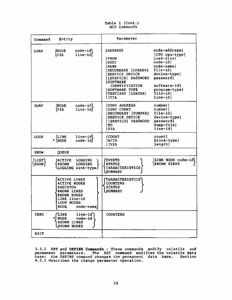
Table 1 (Cant.) NCP Commands
Command Entity
DUMP line-id
LOOP line-id
I
SHOW QUEUE
LIST
LOGGING sink-type
ACTIVE LINES ACTIVE NODES EXECUTOR KNOWN LINES KNOWN NODES LINE line-id
,:: NOD:fde-nam]
ZERO ¥f node-id} line-id
KNOWN LINES NOWN NODES
EXIT
Parameter
[ADDRESS node-address] [CPU cpu-type]
[ FROM load-file] [ HOST node-id] [ NAME node-name] [SECONDARY [LOADER] file-id] [SERVICE DEVICE device-type] [[SERVICE] PASSWORD password] [ SOFTWARE IDENTIFICATION software-id]
[SOFTWARE TYPE program-type] [TERTIARY [LOADER] file-id] : [VIA line-id]
- - -
[DUMP ADDRESS number 1 [DUMP COUNT number 1 [SECONDARY [DUMPER] f ile-id] [SERVICE DEVICE device-type] [[SERVICE] PASSWORD password] [ TO dump-f ilel [VIA line-id]
[ COUNT [WITH : [VIA
count] bloc k-type] leng thl
SINK NODE node-id KNOWN SINKS
UMMARY
SUMMARY
COUNTERS
3.3.1 SET and DEFINE Commands - These commands modify volatile and permanent parameters. The SET command modifies the volatile data base; the DEFINE command changes the permanent data base. Section 4.2.5 describes the change parameter operation.

The general form of the commands is:
{iiiINE} entity parameter
Entity is one of the following:
EXECUTOR LINE line-identification LOGGING sink-type NODE node-identification KNOWN LINES KNOWN LOGGING KNOWN NODES
Parameter is one (or more, if allowed by the implementation) of the parameter options defined for the specified entity.
3.3.1.1 SET and DEFINE EXECUTOR NODE destination-node - The SET and DEFINE EXECUTOR NODE commands, processed by NCP, change the executor node for subsequent commands. Access control information may be supplied as described in Section 3.2.4.
3.3.1.2 SET and DEFINE KNOWN Entity Commands - These commands set volatile and permanent parameters for each one of the specified entities known to the system. The format is:
{:Ll KNOWN plural-entity parameter
Plural entity is one of LINES, LOGGING or NODES.
The parameters are the same as for the SET and DEFINE entity commands (Sections 3.3.1.3, 3.3.1.4, and 3.3.1.5). However, DEFINE KNOWN plural-entity ALL has no meaning. SET KNOWN plural-entity ALL loads all permanent entity parameters into the volatile data base.
3.3.1.3 SET and DEFINE LINE Commands - These commands set volatile and permanent line parameters for the line identified. The format is:
ALL {~~~INE} LINE line-id CONTROLLER
COST COUNTER TIMER DUPLEX NORMAL TIMER SERVICE SERVICE TIMER STATE TRIBUTARY TYPE
controller-mode cost seconds duplex-mode milliseconds service-control milliseconds line-state tributary-address 1 ine-type

where:
1 ine- id Is as specified in Section A.I.
ALL With SET, puts permanent line parameters associated with the line in the volatile data base. With DEFINE, creates a permanent data base entry for one l i n e .
CONTROLLER controller-mode Sets the controller mode for the line. The values for controller mode are as follows:
LOOPBACK This is for sof tware controlled loopback of the controller.
NORMAL This is for normal controller operating mode.
The command automatically turns the line OFF before setting the mode and back to the original state after.
COST cost Sets the routing line cost. The cost is a decimal number in the range 1 to 25. The cost parameter is a positive integer value associated with using a line and is used in the Transport routing algorithm (Transport Functional Specification).
COUNTER TIMER seconds Sets a timer whose expiration causes a line counter logging event. Table 7 lists the line counters. These counters constitute the data for certain logged events (Table 12). The line counters are recorded as data in the event and then zeroed. Seconds is specified as a decimal number in the range 1-65535.
Sets the hardware duplex mode of the line. The possible modes are:
DUPLEX duplex-mode
FULL Full-duplex
HALF Half-duplex
NORMAL TIMER milliseconds Specifies the maximum amount of time allowed to elapse before a retransmission is necessary. This is used for normal operation of the line. Timing is implementation-dependent. This timer applies to the use of the data link protocol (for example, DDCMP) .

SERVICE service-control Specifies whether or not the service operations (loading, dumping, line loopback testing) are allowed for the line. The service-control values are as follows:
ENABLED The line may be put into SERVICE state and service functions performed.
DISABLED The line may not be put into SERVICE state and service functions may not be performed.
SERVICE TIMER milliseconds Specifies the maximum amount of time allowed to elapse before a receive request completes while doing service operations on the line. Service operations are down-line load, up-line dump, or line loop testing. The timer value is an integer number in the range 1-65535. This timer applies to the use of the service protocol (for example, MOP) .
STATE line-state Sets the executor follows:
ON
OFF
SERVICE
CLEARED
line's operational state at the node. The possible states are as
The line is available to its owner for normal use, with the exception of temporary overrides for service functions.
The line is not used by any network or network-related so tware. The 1 ine is functionally non-existent.
This state applies only to the volatile data base (SET command). The line is available for active service functions: load, dump, and line loop. The line can provide passive loopback - direct line software-looped testing (Figure 8) - if no active service function is in progress.
This state applies only to the permanent data base (DEFINE command). A line in this state has space reserved in system tables but has no other databases or parameters in volatile memory. This state is only applicable in systems that can implement it.
If the line is set to its existing state a null operation (NOP) results.

NOTE An implementation may choose to effect service functions in the ON state, as temporary overrides to normal traffic. In this case, error messages must clearly indicate when a line is in a temporary service condition.
TRIBUTARY tributary-address Sets the physical t r i b u t a r y a d d r e s s of the line. The tributary address is a decimal number in the range 0-255. It reflects the bit setting of the hardware switch-pack for the tributary.
TYPE line-type Sets up the line for the data link protocol operation together with the DUPLEX option. Line type is one of the following :
POINT For a point to point line CONTROL For a multipoint control
station TRIBUTARY For a multipoint tributary
3.3.1.4 SET and DEFINE LOGGING Commands - This set of commands is used to control event sinks (where events are logged) and event lists (that control which events get logged). Appendix F specifies events. The command format is:
EVENT event-list [source-qual][sink-node] LOGGING sink-type KNOWN EVENTS [source-qual] [sink-node]
NAME sink-name STATE sink-state
where:
sink-type
[sink-node]
Is one of CONSOLE, FILE, or MONITOR. Determines the ultimate sink for events. Section A.2 specifies the sink-type format.
Specifies a node that receives events. It is of the form:
SINK NODE node-id or
SINK EXECUTOR
This option can either precede or follow KNOWN EVENTS or EVENT event-list. The node identification is specified in Section A.2. If a sink node is not supplied, the default is executor.

[source-qualifier]
EVENT event-list
NAME sink-name
KNOWN EVENTS
STATE sink-state
Selects a specific entity for certain event classes. It has the form:
LINE line-id 0 r
NODE node-id
This option can either precede or follow KNOWN EVENTS or EVENT event-list.
Enables the recording of the events specified by the event list. The event list consists of event class.event type(s). The types (Table 12) are specified in ranges using hyphens and in lists using commas. For example:
Wild card notation indicates all types of events for a particular class. For example :
Establishes device or file names for sink types CONSOLE and FILE, respectively. It specifies a process identification for a MONITOR.
Enables the recording of all events known to the executor node for the specified sink node.
Controls the operation of the sink specified by sink type. The possible values of sink state are:
ON The sink is available for receiving events .
OFF The sink is not available and any events destined for it should be discarded.
HOLD The sink is temporarily unavailable and events should be queued.
The following is an example of the SET LOGGING command:
SET LOGGING CONSOLE SINK NODE MANILA EVENT 6.2 L I N E KDZ-0-1.4

3.3.1.5 SET and DEFINE NODE Commands - These commands set volatile or permanent parameters for a node. Certain parameters can be set only for the executor node or for adjacent nodes. See Table 9. The format for the command is:
where:
node-id
ADDRESS NODE node-id ALL
BUFFER SIZE COUNTER TIMER CPU DELAY FACTOR DELAY WEIGHT DUMP ADDRESS DUMP COUNT DUMP FILE HOST IDENTIFICATION INACTIVITY TIMER INCOMING TIMER LINE LOAD FILE MAXIMUM ADDRESS MAXIMUM BUFFERS MAXIMUM COST MAXIMUM HOPS MAXIMUM LINES MAXIMUM LINKS MAXIMUM VISITS NAME OUTGOING TIMER RETRANSMIT FACTOR ROUTING TIMER SECONDARY DUMPER SECONDARY LOADER SERVICE DEVICE SERVICE LINE SERVICE PASSWORD SOFTWARE
IDENTIFICATION SOFTWARE TYPE STATE TERTIARY LOADER TYPE
node-address
memory-units seconds cpu-type number number number number f ile-id node-id id-str ing seconds seconds 1 ine- id f ile-id number number number number number number number node-name seconds number seconds f ile-id f ile-id device-type 1 ine-id password
software-id program-type node-state f ile-id node-type
ADDRESS node-address
ALL
Specifies node name or node address (Section A.3). In some cases, noted below, the node identification must be a node name. EXECUTOR can be substituted for NODE executor-node-identification.
Sets the address of the executor node. This cannot be used to set the address of any other node.
With SET this moves all parameters associated with the node identified from the permanent data base into the volatile data base. With DEFINE it creates a permanent data base entry for the node identified.

BUFFER SIZE memory-units Sets the size of the line buffers. The size is a decimal integer in the range 1-65535. This size is in memory units (Appendix C) . It is the actual buffer size and therefore must take into account such things as protocol overhead. There is one buffer size for all lines.
COUNTER TIMER seconds
CPU cpu-type
DELAY FACTOR number
DELAY WEIGHT number
DUMP ADDRESS number
DUMP COUNT number
DUMP FILE f ile-id
Sets a timer whose expiration causes a node counter logging event. Node counters are listed in Table 10. They constitute data for certain logged events (Table 12). The node counters will be recorded as data in the event and then zeroed. Seconds is specified as a decimal number in the range 1-65535.
Sets the default target node CPU type for down-line loading the adjacent node. The possible values are:
PDP 8 PDP 11 DECSYSTEM 10 DECSYSTEM 20 VAX
Sets the number by which to multiply one sixteenth of the estimated round trip delay to a node to set the retransmission timer to that node. The round trip delay is used in an NSP algorithm that determines when to retransmit a message (NSP functional specification) . The number is decimal in the range 1-255.
Sets the weight to apply to a current round trip delay estimate to a remote node when updating the estimated round trip delay to a node. The number is decimal in the range 1-255. On some systems the number must be 1 less than a power of 2 for computational efficiency (NSP functional specification).
Sets the address in memory to begin an up-line dump of the adjacent node.
Determines the default number of memory units to up-line dump from the adjacent node.
Sets the identification of the file to write to when the adjacent node is up-line dumped. The file identification is a string that is interpreted depending on the system where the file is.

HOST node-id Sets the identification of the host node. For the executor, this is the node from which it requests services. For an adjacent node, it is a parameter that the adjacent node receives when it is down-line loaded. If no host is specified, the default is executor node.
IDENTIFICATION id-string Sets the text identification string for the executor node (for example, "Research Lab") . The identification string is an arbitrary string of 1-32 characters. If the string contains blanks or tabs it must be enclosed in quotation marks (Ig). A quotation mark within a quoted string is indicated by two adjacent quotation marks ( " I' ) .
INACTIVITY TIMER seconds Sets the maximum duration of inactivity (no data in either direction) on a logical link before the node checks to see if the logical link still works. If no activity occurs within the maximum number of seconds, NSP generates artificial traffic to test the link (NSP functional specification). The range is 1-65535.
INCOMING TIMER seconds Sets the maximum duration between the time a connect is received for a process and the time that process accepts or rejects it. If the connect is not accepted or rejected by the user within the number of seconds specified, Session Control rejects it for the user. The range is 1-65535.
LINE line-id
LOAD FILE file-id
Defines a loop node and sets the identification of the line to be used for all traffic from the node. Loop node identification must be a node name. No line can be associated with more than one node name.
Sets the identification of the file to read from when the node is down-line loaded. The file identification is a string that is interpreted depending on the file system of the executor.
MAXIMUM ADDRESS number Sets the largest node address and, therefore, number of nodes that can be known about. The number is an integer in the range 1-65535.
MAXIMUM BUFFERS number Sets the total number of buffers allocated to all lines. In other words, it tells Transport how big its own buffer pool is. The count number is a decimal integer in the range 0-65535.

MAXIMUM COST number
MAXIMUM HOPS number
MAXIMUM LINES number
MAXIMUM LINKS number
MAXIMUM VISITS number
NAME node-name
Sets the maximum total path cost allowed from the executor to any node. The path cost is the sum of the line costs along a path between two nodes (Transport functional specification). The maximum is a decimal number in the range 1-1023.
Sets the maximum routing hops from the node to any other reachable node. A hop is the logical distance over a line between two adjacent nodes (Transport functional specification). The maximum is a decimal number in the range 1-31.
Sets the maximum number of lines that this node can know about. The number is a decimal in the range 1-65535.
Sets the maximum active logical link count for the node. The count is a decimal number in the range 1-65535.
Sets the maximum number of nodes a message coming into this node can have visited. If the message is not for this node and the MAXIMUM VISITS number is exceeded, the message is discarded. The number is a decimal in the range MAXIMUM HOPS to 255.
Sets the node name to be associated with the node identification. Only one name can be assigned to a node address or a line identification. No name can be used more than once in the node.
OUTGOING TIMER seconds Sets a time-out value for the duration between the time a connect is requested and the time that connect is acknowledged by the destination node. If the connect is not acknowledged within the number of seconds specified, Session Control returns an error. The range is 1-65535.
RETRANSMIT FACTOR number Sets the maximum number of times the source NSP will restart the retransmission timer when it expires. If the number is exceeded, Session Control disconnects the logical link for the user (NSP functional specification). The number is decimal in the range 1-65535.
ROUTING TIMER seconds Sets the maximum duration before a routing update is forced. The routing update produces a routing message for an adjacent node (Transport functional specification). Seconds is a decimal integer in the range 1-65535.
SECONDARY DUMPER file- id Sets the identification of the secondary dumper file for up-line dumping the adjacent node.
SECONDARY LOADER file-id Sets the identification of the secondary loader file, for down-line loading the adjacent node.
SERVICE DEVICE device-type Sets the service device type that the adjacent node uses for service functions when in service slave mode (see Section 4.1.4.2). The device type is one of the standard line device mnemonics.
SERVICE LINE line-id Establishes the line to the adjacent node for down-line loading and up-line dumping. Sets the default if the VIA parameter of either the LOAD or DUMP commands is omitted. When down line loading a node (Section 3.3.4), the node identification must be that of the target node.
SERVICE PASSWORD password Sets the password required to trigger the bootstrap mechanism on the adjacent node. The password is a hexadecimal number in the range 0-FFFFFFFFFFFFFFFF (64 bits).
SOFTWARE IDENTIFICATION Sets the identification of the software sof tware-id that is to be loaded when the adjacent
node is down-line loaded. Software-id contains up to 16 alphanumeric characters.
SOFTWARE TYPE program-type Sets the initial target node software program type for down-line loading the adjacent node. Program type is one of:
SECONDARY [LOADER] TERTIARY [ LOADER] SYSTEM
STATE node-state Sets the operational state of the executor node. The possible states are:
ON Allows logical links.
SHUT
OFF Allows no new links, terminates existing links, and stops routing traffic through.
Allows no new logical links, does not destroy existing logical links, and goes to the OFF state when all logical links are gone.
RESTRICTED Allows no new incoming logical links from other nodes.
TERTIARY LOADER file-id Sets the identification of the tertiary loader file, for down-line loading the adjacent node.

TYPE node-type Sets the type of the node as one of the following:
ROUTING Full routing node.
NONROUTING Node with no routing capability.
PHASE I1 Phase I1 node.
3.3.2 CLEAR and PURGE Commands - These commands clear parameters from the volatile and permanent data bases. The CLEAR command affects the volatile data base; the PURGE command affects the permanent data base. Not all parameters can be cleared individually. A cleared or purged parameter or entity identification is the same as one that has not been set or defined. The general form of the command is:
{ ~ ~ ~ ~ ~ } entity parameter
The entities are the same as for the SET and DEFINE commands (Section 3.3.1).
3.3.2.1 CLEAR and PURGE EXECUTOR NODE C o m m a n d s - The CLEAR EXECUTOR NODE command resets the executor to the node on which NCP is running. Note that CLEAR EXECUTOR does not return the executor to that defined in the permanent data base. The PURGE EXECUTOR NODE command redefines the executor in the permanent data base as the local node. Access control is reset as well.
3.3.2.2 CLEAR and PURGE KNOWN E n t i t y C o m m a n d s - These commands clear and purge parameters for all of the specified entity known to the system. The format of the command is:
{ ~ ~ ~ ~ ~ } KNOWN pl ural-enti ty parameter
Plural entity is one of LINES, LOGGING or NODES.
Parameter is one or possibly more of the parameters associated with the CLEAR and PURGE entity commands (Sections 3.3.2.3, 3.3.2.4, and 3.3.2.5).
3.3.2.3 CLEAR and PURGE L I N E Commands - These commands clear line parameters from the volatile and permanent data bases. The command format is:
{ ~ ~ ~ ~ ~ } LINE 1. ine-id ALL COUNTER TIMER
where:
ALL
COUNTER TIMER
Clears all parameters associated with the 1 ine identified and the 1 ine identification itself from the volatile or permanent data base.
Clears the timer that controls the periodic loqqinq of the line's counters. This implies that t h e y are no l o n g e r t o be logged.
3.3.2.4 CLEAR and PURGE LOGGING Commands - These commands, in conjunction with the SET and DEFINE LOGGING commands, control event sinks and event lists. The same general definitions (sink-node, sink-type, and source-qualifier) that apply to the SET LOGGING command (Section 3.3.1.4) apply here.
EVENT event-list [source-qua11 [sink-node] {ziz:] LOGGING sink-type KNOWN EVENTS [source-qua11 [sink-node] NAME
where:
EVENT event-list
NAME
KNOWN EVENTS
Disables the recording of the events specified by the event list (event-class.event-type). Appendix F specifies events. Section 3.3.1.4 details the format of the event list. The sink node option turns off events for the specified sink node. If no sink node is specified, the EXECUTOR is assumed.
Clears the sink name assigned to the sink type. The sink then becomes the default for the specific system, either no sink or some system-specific standard.
Disables the recording of all events known to the executor node for the sink node.
3.3.2.5 CLEAR and PURGE NODE Commands - These commands clear volatile (using CLEAR) or permanent (using PURGE) parameters for the node. Node identification can be either a node name or a node address, except for the LINE option where it must be a name. EXECUTOR may substitute for NODE executor-node-identification.
ALL NODE node-id COUNTER TIMER
C PU DUMP ADDRESS DUMP COUNT DUMP FILE HOST IDENTIFICATION INCOMING TIMER LINE LOAD FILE

where :
ALL
DUMP FILE
HOST
INCOMING TIMER
LINE
IDENTIFICATION
LOAD FILE
NAME
OUTGOING TIMER
SECONDARY DUMPER
SECONDARY LOADER
SERVICE DEVICE
SERVICE LINE
SERVICE PASSWORD
SOFTWARE IDENTIFICATION
SOFTWARE TYPE
TERTIARY LOADER
NAME OUTGOING TIMER SECONDARY DUMPER SECONDARY LOADER SERVICE DEVICE SERVICE LINE SERVICE PASSWORD SOFTWARE IDENTIFICATION SOFTWARE TYPE TERTIARY LOADER
Clears all parameters associated with the node identified.
Clears the identification of the file to write,to when the node is up-line dumped.
Clears the identification of the host node.
Clears the node's incoming timer.
Clears the loop node entry associated with the line.
Clears the node's identification string.
Clears the identification of the file to read from when the node is down-line loaded.
Clears the node name for the node.
Clears the node's outgoing timer.
Clears the identification of the secondary dumper file.
Clears the identification of the secondary loader file.
Clears the service device type.
Clears the identification of the line associated with the node-id specified for the purposes of down-line load, up-line dump, and line loop test.
Clears the password required to trigger the bootstrap mechanism on the node.
Clears the identification of the target's initial load software.
Clears the identification of the target node software program type for down-line loading.
Clears the identification of the tertiary loader file.
3.3.3 TRIGGER Command - This command triggers the bootstrap of the target node so that the node will load itself. It initiates the load of an unattended system. This command will work only if the target node either recognizes the trigger operation with software or has the necessary hardware in the correct state. Section 3.3.4 describes the parameter options. Parameters specified with a command override the default parameters of the same type. Section 4.2.3 describes the trigger operation. The format of the command is:
TRIGGER node-id [[SERVICE] PASSWORD password] } [VIA 1 ine-id] line-id [[SERVICE] PASSWORD password]
3.3.4 LOAD Command - This command initiates a down-line load. There are two variations. Section 3.3.4.1 describes the parameters used with this command. Node identification is either the node name or the node address of the target node. This command works only if the conditions for trigger are met, or if the target node has been triggered locally. Section 4.2.1 describes the operation of down-line loading.
3.3.4.1 LOAD NODE Command - This loads the node identified on the line identified or on the line obtained from the permanent data base. Any parameter not specified in the command line defaults to whatever is specified in the permanent data base at the executor node.
LOAD NODE node-id [ADDRESS node-address] [CPU cpu-type I [ FROM load-f ile] [ HOST node-id] [ NAME node-name] [SECONDARY [LOADER] file-id] [SERVICE DEVICE device-type] [[SERVICE] PASSWORD password] [ SOFTWARE
IDENTIFICATION software-id] [SOFTWARE TYPE program-type] [TERTIARY [LOADER] f ile-id] [VIA line-id]
where :
[ADDRESS node-address] Indicates the address the target node is to use.
[CPU cpu-type]
[FROM load-f ile]
[HOST node-id]
Indicates the target CPU type. The possible values are:
PDP 8 PDP 11 DECSYSTEM 10 DECSYSTEM 20 VAX
Indicates the file from which to load.
Indicates the identification of the host to be sent to the target node.

[NAME node-name] Specifies the name the target node is to use.
[ SECONDARY [ LOADER] f ile-id
[SERVICE DEVICE dev ice-type]
[ [SERVICE] PASSWORD password]
[SOFTWARE IDENTIFICATION software-id]
[SOFTWARE TYPE program-type]
[TERTIARY [LOADER] f ile-id]
[VIA line-id]
Provides the identification of the secondary loader file.
Indicates the device type that the target node will use for service functions when it is in service slave mode (see Section 4.1.4.2).
Supplies the boot password for the target node. A hexadecimal number in the range 0-FFFFFFFFFFFFFFFF.
Provides the load software identification. Software identification is up to 16 alphanumeric characters.
Indicates the target node sof tware program type. Program-type is one of:
SECONDARY [LOADER] TERTIARY [LOADER] SYSTEM
Provides the identification of the tertiary loader file.
Indicates the line to load over.
3.3.4.2 LOAD VIA Command - With this command format, the executor loads the target over the specified line, obtaining the node identification from the permanent data base if necessary. The command format is:
LOAD VIA line-id [ADDRESS node-address] [ CPU cpu-type I [ FROM load-file] [HOST node- id 1 [ NAME node-name] [SECONDARY [LOADER] f ile-id] [ S E R V I C E DEVICE dev ice-type] [ [SERVICE] PASSWORD password] [SOFTWARE IDENTIFICATION file-id] [SOFTWARE TYPE program-type] [TERTIARY [LOADER] f ile-id]
3.3.5 DUMP Command - This command performs an up-line dump. Parameters not supplied default to those in the permanent data base at the executor node (see Section 3.3.1.5). There are two variations, as follows:
DUMP NODE node-id [[DUMP] ADDRESS number 1 [ [DUMP] COUNT number ] [ TO dump-f ile] [SECONDARY [DUMPER] f ile-id] [SERVICE DEVICE dev ice-type] [[SERVICE] PASSWORD password] [VIA line-identification]

DUMP VIA line-id [ [DUMP] ADDRESS number I [ [DUMP] COUNT number I 1 TO dump-f ilel [SECONDARY [DUMPER] file-id] [SERVICE DEVICE device-type] [[SERVICE] PASSWORD password]
3.3.6 LOOP Command - This command causes test blocks to loop back from the specified line or node. It is limited by what the Loopback Mirror and the passive looper can handle. There are two variations, as described in the next two sections. Section 4.2.4 describes the loop test operation.
When a loop test fails, the error message contains added explanatory information, in the form either
UNLOOPED COUNT = n or
MAXIMUM LOOP DATA = n
Where the unlooped count is the number of messages not yet looped when the test failed and maximum loop data is the maximum length that can be requested for the loop test data.
3.3.6.1 LOOP LINE Command - The line loop performs loopback testing on a specific line, which is unavailable for normal traffic during the test. The optional parameters can be entered in any order. Parameters not specified default to their values in the permanent data base at the executor node. The command format is as follows:
LOOP LINE line-id
where :
LOOP COUNT count
LOOP LENGTH length
[COUNT count] [WITH bloc k-type] [ LENGTH length]
Sets the block count for loop tests. Count is an integer in the range 0 to 65535.
Sets the length of a block for loop tests. Length is an integer in the range 0 to 65535.
LOOP WITH block-type Sets the block-type for loop tests. The possible values for block-type are ONES, ZEROES or MIXED.
3.3.6.2 LOOP NODE Command - A node loop will not interfere with normal traffic, but will add to the network load. The parameter options available are the same as for the line loop (Section 3.3.6.1). The node loop can take place within one node or between two nodes. In the latter case, the remote node is the one specified (Figures 6 and 7, Section 4.2.4). EXECUTOR may be substituted for NODE executor-node-identification.

3.3.7 SHOW QUEUE Command - This command displays the status of the last few commands entered at the default executor. The number of commands displayed varies with each implementation. The executor for commands not sent across the network is shown as N/A (not applicable). Completed commands need not be displayed. Every command in progress must be shown in request number order. Implementations that do not allow multiple outstanding commands do not need this command.
An example of output follows:
REQUEST #13Ã SHOW QUEUE
REQUEST NUMBER EXECUTOR COMMAND STATUS
9 6 (HNGKNG) LOAD FAILED 1 0 6 (HNGKNG) SHOW COMPLETE 11 1 0 (MANILA) LOAD IN PROGRESS 1 2 6 (HNGKNG) SET COMPLETE 1 3 N/ A SHOW I N PROGRESS
3.3.8 SHOW and LIST Commands - These commands are used to display information. The SHOW command displays information from the volatile data base. The LIST command displays information from the permanent data base. The general command format is either:
{::::I entity [information-type] [qualifiers]
or:
f SHOW '>
L iiiSTJ information-type] entity [qualifiers]
The entities are:
ACTIVE LINES ACTIVE LOGGING ACTIVE NODES EXECUTOR KNOWN LINES KNOWN LOGGING KNOWN NODES LINE 1 ine-id LOGGING sink-type LOOP NODES NODE node-name
KNOWN plural entities are all those known to the system, regardless of state. ACTIVE plural entities are a subset of KNOWN as defined in the glossary. When displaying plural nodes, the executor display is returned first, if it is included. Any loop nodes are returned last.
The information types are:
CHARACTERISTICS COUNTERS EVENTS STATUS SUMMARY

Appendix A contains definitions of the information types. The tables in Appendix A specify the information returned for each information type on the SHOW command. The qualifiers vary according to the specific entity, except one that is common to all entities that have qualifiers:
TO alternate-output
This qualifier directs the output to an alternate output file or device (for example, a disk file or a line printer) rather than the default terminal display. The output is text in the same format it would have on the terminal. The format of the alternate output specification is system-dependent.
When there is no information to display in response to a SHOW command display the phrase "no information" in place of the data.
3.3.8.1 Information Type Display Format - All of the SHOW and LIST command information-type options have the same general output format. The header of that format is:
REQUEST #n; entity information-type AS OF dd-mon-yy hh-nun
For example:
REQUEST #21; KNOWN LINES STATUS AS OF 8-JUL-79 10:55
REQUEST #43Ã EXECUTOR NODE CHARACTERISTICS AS OF 10-SEP-79 10:56
REQUEST #45; KNOWN NODES SUMMARY AS OF 10-SEP-79 10:57
The requested information follows the header. The general format of the information is:
entity-type = entity-id
data
If the entity type is NODE, then one of EXECUTOR, REMOTE, or LOOP must precede it.
This information format repeats for each individual entity. A SHOW or LIST command with no information type should default to SUMMARY.
3.3.8.2 Counter Display Format - Counters are identified by standard type numbers as defined in Tables 7 and 10, Appendix A. Counters are displayed in ascending order by type. The display format for counters is:
value description[, INCLUDING:] qualifier-1
qualifier-n
The value is the value of the counter, up to 10 digits for a 32-bit counter. It is a decimal number with no leading zeros. Zero values distinguish the case of no-counts from the case where a counter is not

kept. If the counter has overflowed, it is displayed as the overflow value minus one, preceded by a greater-than sign. for example, an. overflowed 8-bit counter would be displayed as ">254."
The description is the standard text that goes with the counter type as defined in Tables 7 and 10. If the counter type is not recognized, the description "COUNTER #n" is used, where n is the counter type number.
~f the counter has an associated bit map, the word "including" is appended to the description, with a list of qualifiers. A qualifier is the standard text for the bit position in the bit map. A qualifier is displayed only if the corresponding bit is set. If the standard text for the bit is not known, the qualifier "QUALIFIER $n" is used, where n is the bit number.
For example:
REQUEST #21Ã L I N E COUNTERS AS OF 20-FEB-79 15:29
L I N E = DUP-6
ARRIVING PACKETS RECEIVED DEPARTING PACKETS SENT ARRIVING CONGESTION LOSS TRANSIT PACKETS RECEIVED TRANSIT PACKETS SENT TRANSIT CONGESTION LOSS BYTES RECEIVED BYTES SENT DATA BLOCKS RECEIVED DATA BLOCKS SENT DATA ERRORS INBOUND; INCLUDING:
NAK'S SENT REP RESPONSE DATA ERRORS OUTBOUND
3.3.8.3 Tabular and Sentence Formats - Non-counter information permits two general formats. The first is easier to scan, the second is more extensible. The first is a tabular form, with each individual entity fitting on one line under a global header. Using this form, unrecognized parameter types are more clumsily handled and the amount of information per individual entity is limited to what will fit on one output line. The second is a sentence form. It adapts easily to a large number of parameters per individual entity and readily handles unrecognized parameter types.
In either form, the order of parameter output is the same in all implementations, even though in a particular implementation, some parameters may be unrecognized. The output format for unrecognized parameters is:
PARAMETER #n = value
where n is the decimal parameter number and value is the parameter value, formatted according to its data type.
Appendix A describes parameter types and their output order. In the sentence form of output, parameters that are logically grouped together should appear- on the same line. Appendix A details these logical groupings.

The general output format of the data for tabular form is:
entity-type parameter-type parameter-type...
entity-id parameter-value parameter-value ...
An example of output of the data in tabular form follows:
REQUEST $39; KNOWN LINES STATUS AS OF 18-SEP-78 15:20
L I N E STATE ADJACENT NODE
DMC- 1 ON 4 (BOSTON) DMC-3 OFF DL-0 ON-LOADING 1 2
If NCP did not recognize an adjacent node parameter, the output would specify the type number of the parameter and the value according to the parameter data type. (See Tables 6 to 10, Appendix A, for type numbers . ) The general output format of the data for sentence form is:
entity-type = entity-id
par-type = par-value, par-type = par-value, ... par-type = par-value, ...
An example of output of the data for sentence form follows.
REQUEST $39; KNOWN LINES STATUS AS OF 18-SEP-78 15:20
L I N E = DMC-1
STATE = ON> ADJACENT NODE = 4 (BOSTON)
L INE = DMC-3
STATE = OFF
L INE = DL-0
STATE = ON? ADJACENT NODE = 1 2
The output format for the logging entity differs in the event display. For example, for the following command:
SHOW LOGGING CONSOLE SUMMARY KNOWN SINKS

A correct output would be
LodSind Summary as o f 7-MAR-79 10 : 55
Lo£'jiris CONSOLE
S ta te == ON? NAME = COOS
Sink node = 15 <HALDIR)v EVENTS =
0 . 0 ~ 6 L i n e KDZ-0-1.39 3.6-7 3.6-13
Sink node = 16 (EOWYN)? Events =
0 .0 L i n e KDZ-0-1.3~ 6.0-1
3.3.8.4 Restrictions and Rules on Returns - The following restrictions and rules apply to returns on SHOW and LIST entity information type commands.
1. Node parameters. The parameters displayed for the SHOW and LIST NODE commands depend on which node is specified. Table 8, Appendix A, indicates these restrictions. The keywords EXECUTOR, REMOTE or LOOP must precede NODE in a display of a node to clarify what is displayed.
2. Line states. The returns on the SHOW and LIST LINE STATUS commands must show the line substate as well as the state. Table 2, following, lists line states and substates. Table 3, following, lists all the possible line state transitions and their causes.
3. Loop nodes. Information for a single loop node is returned when requested by the loop node name. Information for multiple loop nodes is returned at the end of the display for KNOWN or ACTIVE NODES. It is the exclusive display for LOOP NODES.
4. Counters. COUNTERS can only be displayed with the SHOW commands, and with line or node entities.
5. Events. EVENTS applies only to the logging entity. Sink node identification must be address and name (if a name exists), even for the executor.
3.3.9 ZERO Command - This command causes a specified set of counters to be set to zero. The command generates a counters zeroed event that causes counters to be logged before they are zeroed. The counters zeroed are those the executor node supports for the specified entity. The command format is:
node-id line-id [COUNTERS]
KNOWN LINES KNOWN NODES

3.3.10 EXIT Command - This command terminates an NCP session.
Table 2 Network Management Line States
State 1 Substate Meaning 1 I OFF
ON
-STARTING
-AUTODUMPING Line in use by Line Watcher for
none
running
Line in owner (Transport) initialization cycle
-REFLECTING
-AUTOSERVICE
-AUTOLOADING
Line not usable by anything
Line in normal use by owner
Line in use for passive (direct line-software looped) loopback
Line reserved for Line Watcher use
Line in use by Line Watcher for load
I -LOOPING Line in use by operator for active line loopback
-AUTOTRIGGERING
-LOAD1 NG
-DUMPING
Line in use by Line Watcher for trigger
~ i n e in use by operator for load
Line in use by operator for dump
SERVICE 1 idle Line reserved by operator for active service function
-TRIGGERING Line in use by operator for trigger
I -LOADING 1 Line in use by operator for load
-REFLECTING
1 -DUMPING 1 Line in use by operator for dump
Line in use for passive (direct line-software looped) loopback
-LOOPING
-TRIGGERING
Line in use by operator for active line loopback
Line in use by operator for trigger

Table 3 Line State Transitions
I o l d State I New State I Cause of Change
Any
ON-STARTING
I ON-STARTING Data Link restarted by Transport (from either end)
OFF
Operator command, SET LINE STATE ON
SERVICE
I ON-REFLECTING Line loopback message received from remote system
Operator command, SET LINE STATE OFF
Operator command, SET LINE STATE SERVICE
I ON-AUTOSERVICE Service request received by Line Watcher
I I ON-LOADING 1 Operator command, LOAD I
t ON-DUMPING
ON-LOOPING
ON-TRIGGERING
Transport initialization complete
Operator command, DUMP
Operator command, LOOP LINE
Operator command, TRIGGER
SERVICE Operator command, SET LINE STATE SERVICE
1 ON-AUTOSERVICE Service request received by Line Watcher
ON-REFLECTING
I 1 ON-LOADING 1 Operator command, LOAD
Line loopbac k message received from remote system
I I t ON-DUMPING Operator command, DUMP
I I
ON-LOOPING 1 Operator command, LOOP LINE I
ON-TRIGGERING
SERVICE
Operator command, TRIGGER
Operator command, SET LINE STATE SERVICE
1 ON-REFLECTING ON-STARTING Passive line loopback terminated
1 ON-AUTOSERVICE
1 Service request received by Line Watcher
(continued on next page)

Table 3 (Cant.) Line State Transitions
1 ON-DUMPING loper ator command, DUMP
Cause of Change Old State
ON-REFLECTING (CONT. )
I ON-LOOPING operator command, LOOP LINE
New State
1 ON-TRIGGERING 0perat0r command, TRIGGER
ON-LOADING Operator command, LOAD
ON-AUTOSERVICE
SERVICE
ON-STARTING
Operator command, SET LINE STATE SERVICE
ON-AUTOLOADING
Line released by Line Watcher
Load initiated by Line Watcher
1 ON-AUTODUMPING Dump initiated by Line Watcher
ON-AUTOTRIGGERING
ON-LOOPING
Trigger initiated by Line Watcher
1 ON-STARTING
- -- --
Load complete
Dump complete
Trigger complete
Load complete
Dump complete
-
ON-AUTOLOAD ING
ON-AUTODUMPING
ON-AUTOTRIGGERING
ON-LOADING
ON-DUMPING
~ c t i v e line loop complete \
-
ON-AUTOSERVICE
ON-AUTOSERVICE
ON-AUTOSERVICE
ON-STARTING
ON-STARTING
ON-TRIGGERING
SERVICE
--
(continued on next page)
SERVICE
ON-STARTING
SERVICE-REFLECTING
SERVICE-LOADING
SERVICE-DUMPING
- - 1
Trigger complete
Line loopback message received from remote system
Operator command, LOAD
Operator command, DUMP
SERVICE-LOOPING
SERVICE-TRIGGERING
ON-STARTING
Operator command, LOOP LINE
Operator command, TRIGGER
Operator command, SET LINE STATE ON

Table 3 (Cont.) Line State Transitions
Old State
SERVICE-REFLECTING
SERVICE-LOADING
SERVICE-DUMPING
SERVICE-LOOPING
SERVICE-TRIGGERING
-
New State I Cause of Change I
SERVICE-DUMPING 1 operator command, DUMP 1
SERVICE
SERVICE-LOADING
Passive 1 ine loopback complete
Operator command, LOAD
SERVICE 1 Load complete 1
SERVICE-LOOPING
SERVICE-TRIGGERING
SERVICE
Operator command, LOOP LINE
Operator command, TRIGGER
1 Dump complete SERVICE
SERVICE
Active line loop complete
Trigger complete

4.0 NETWORK MANAGEMENT LAYER
This layer, the heart of Network Management, contains the modules and data bases providing most of the functions requested by Network Control Program (NCP) commands. The Network Management layer also provides automatic event-logging and an interface to user programs for network control and information exchange. Section 4.1 describes the Network Management modules. Section 4.2 outlines the operation of the functions associated with each Network Information and Control Exchange (NICE) message, including algorithms for implementation. Section 4.3 details the Network Management layer message formats as well as NICE connect and accept data formats and the Event message binary data format.
4.1 Network Management Layer Modules
This section describes the Network Management layer modules (Figure 2) and some of the algorithms for implementing them.
4.1.1 Network Management Access Routines and Listener - The Network Management Access Routines receive NICE commands from the Network Control Program (NCP) and user programs. Network Management Access Routines pass NICE messages to the remote or local Network Management Listener via logical links. They also pass local function requests to the Local Network Management Functions. The Network Management Listener receives NICE command messages via logical links from the Network Management Access Routines in the local node or in other nodes.
he method used for processing Network Management functions within a single node is implementation-dependent. The Network Management Access Routines can pass all local function requests to the Local Network Management Functions. Alternatively, the access routines can pass NICE messages to the Network Management Listener via a logical link. The latter method cannot be used for functions, such as turning the network on, that occur before a logical link is possible.
4.1.2 Local Network Management Functions - The Local Network Management Functions receive the following types of requests from other modules:
System-independent function requests from the local NCP via the Network Management Access Routines.
NICE function requests from other nodes via the Network Management Listener.
NICE function requests from the local node via the Network Management Listener.
Automatically-sensed service requests from the Line Watcher.
The Local Network Management Functions have the following interfaces to other modules or layers:
a Line Service Functions. The Local Network Management Functions have a control interface to the Line Service Functions for setting and changing line states. The Local
Network Management Functions have a "user" interface to the Line Service Functions for handling functions that are necessary for service functions (such as up-line dumping, down-line loading, and line level testing) to be performed.
Control interfaces to lower layers. The Local Network Management Functions interface with lower layers directly for control and observation of lower level counters and parameters. An example of such an interface is examining a node counter.
Function requests to lower layers and to local operating system. The Local Network Management Functions pass such function requests as file access, node level loopback, and timer setting to the application layer or to the local operating system in the form of system-dependent calls.
Event logging. The Local Network Management Functions interface with the Event Logging module in order to set event logging parameters that control such things as which events are logged and at what sink node they are logged.
Section 4.2 supplies algorithms for handling Network Management function requests.
4.1.3 Line Watcher - The Line Watcher module senses data link level service requests to up-line dump or load coming on a line from an adjacent node.
The Line Watcher senses a request by calling the Line Service Functions. Using parameters from that message, the Line Watcher then determines the request type and calls the Local Network Management Functions to accomplish the request.
The algorithm for implementing the Line Watcher is as follows:
Call L i n e Serv ice Functions t o g e t L i n e Serv ice reouest f o r l i n e I F L i n e Serv ice reouested
Set l i n e s t a t e t o ON-AUTOSERVICE (Local Network Management Functions)
Determine f u n c t i o n needed Call Network Manasement Functions t o perform needed furact iori ( s ) Reset l i n e s t a t e t o ON (Local Network. Management F ~ ~ r ~ c t i o r ~ s )
ENDIF
Section 4.2.5 describes the algorithms for setting and resetting line states for the Line Watcher.
4.1.4 Line Service Functions - The Line Service Functions provide Local Network Management Functions with line state changing and line handling services. They are used for functions requiring a direct interface to the Data Link layer. The functions that use the Line Service Functions are:
Down-line load (Section 4.2.1)
Up-line dump (Section 4.2.2)
Trigger bootstrap (Section 4.2.3)

Line test (Section 4.2.4.2)
1. Active at the executor node
2. Passive at the target node (for unattended system)
Set line state (Section 4.2.5)
The Line Service Functions provide the following services:
Condition a node to be dumped, loaded or have a loopback test performed. This state of the target node is called service slave mode, a mode in which the entire processor is taken over. Control rests with the executor.
Notify a higher level that active line services (load, dump) are needed.
Provide transmit/receive interface to higher level for active line services.
4.1.4.1 States and Substates - To arbitrate the use of the line, Line Service Functions maintain states and substates. Table 4, following, shows these as well as corresponding line states and substates displayed with the NCP SHOW LINE STATUS command. Table 4 also shows related Line Service functions.
The line can go from any substate to service slave mode.
Table 4 Line Service States, Substates and Functions and
Their Relationship to Line States
Line Line State Substate
Line Service State
passive
passive 1 reflecting 1 Passive loopback
Line Service Substate
passive
open lloading 1 Receive and transmit loading messages
Line Service Function in Progress or Allowed
idle
open ldumping 1 Receive and transmit dumping messages
Pass message to higher level
idle Pass message to higher level
open
(Continued On Next Page)
triggering Receive and transmit triggering messages

Table 4 (Cont.) Line Service States, Substates and Functions and
Their Relationship to Line States
Line Service Substate state
-LOOPING open
Line Service Substate
Line Service Function in Progress or Allowed
Line State
ON looping Receive and transmit looping nessages
-AUTOSERVICE closed idle Pass message to higher level
Passive loopback
Receive and transmit loading messages
I
-REFLECTING closed reflecting
loading
-AUTODUMPING open dumping Receive and transmit dumping messages
-AUTOTRIGGERING open 0 triggering Receive and transmit triggering
closed - SERVICE idle Pass message to higher level
SERVICE -REFLECTING 1 closed reflecting Passive loopback 1 SERVICE loading Receive and
transmit loading messages
SERVICE dumping --
Receive and transmit dumping messages
SERVICE open triggering Receive and transmit triggering messages
SERVICE looping Receive and transmit looping messages
OFF I off idle

4.1.4.2 Priority Control - The Line Service Functions must make sure that higher priority functions take over, and that lower priority functions are resumed when higher priority functions are complete. The priorities are as follows from highest (1) to lowest (5):
1. Enter service slave mode (MOP primary mode) for passive line loopback, receiving down-line load, sending up-line dump, and transferring control. Control rests with the executor node. Some implementations may require hardware support.
2. NO line operation (off state). In some implementations, this is the first priority.
3. Active service functions (send down-line load, trigger bootstrap, receive up-line dump, perform active line loopback) .
4. Passive line loopback.
5. Normal operation (line available for use by owner).
4.1.4.3 Line State Algorithms - The algorithms that follow are a model for implementation of the Line Service states. If these algorithms are followed, the proper state transitions will take place. The algorithms refer to Data Link maintenance mode. This is a Data Link layer mode (DDCMP functional specification).
Set line state to off:
Call Data Link to halt line Set substate to idle
Set line state to passive:
IF line state is off or closed IF substate is not reflectin*
Set substate to idle ENDIF
ELSE Fai 1
END IF
Set l i n e s tate to closed:
IF line state is off? passive? or open IF line state is off or passive and substate is not reflecting
Call Data Link to set line node to maintenance Set Sl~bstate to idle
ENDIF ELSE
Fai 1 ENDIF
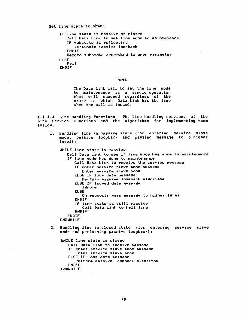
Set line state to o m :
IF line state is passive or closed Call Data Link to set line mode to maintenance IF substate is reflectind
Terminate passive loovback ENDIF Record substate according to open parameter
ELSE Fai 1
ENDIF
NOTE
The Data Link call to set the line mode to maintenance is a single operation that will succeed regardless of the state in which Data Link has the line when the call is issued.
4.1.4.4 Line Handling Functions - The line handling services of the Line Service Functions and the algorithms for implementing them follow.
1. Handling line in passive state (for entering service slave mode, passive loopback and passing message to a higher level) :
WHILE line state is passive Call Data Link to see if line mode has done to maintenance IF line mode has done to maintenance
Call Data Link to receive the service message IF enter service slave mode message
Enter service slave mode ELSE IF loov data message
Perform passive loopback alcd-irithm ELSE IF looped data message
Ignore EL.SE
On rec~uest~ pass message to higher level ENDIF IF line state is still passive
Call Data Link to halt line ENDIF
ENDIF ENDWHILE
2. Handling line in closed state (for entering service slave mode and performing passive loopback):
WHILE line state is closed Call Data Link to receive message IF enter service slave mode message
Enter service slave mode ELSE IF loov data message
Perform passive loopback algorithm END IF
ENDWH I LE

3 . Handling line in open State (for entering service slave mode, receiving a message, and transmitting a message):
UHIL-E l i n e s t a t e is open IF t r a n s m i t reaues ted
C a l l Data Link t o t r a n s m i t message ELSE IF r ece ive reouested
IF d a t a overrun recorded Return d a t a overruri e r r o r
ELSE Post r ece ive reouested
ENDIF ENDIF C a l l Data Link t o r ece ive message IF e n t e r s e r v i c e s l a v e mode message
En te r s e r v i c e s l a v e mode ELSE
IF r ece ive posted Return message
ELSE Record d a t a overrun
ENDIF ENDIF
ENDWHILE
4. Handling passive line loopback (passive at the remote or target node) :
( I n i t i a l message a l r eady r ece ived ) S e t s u b s t a t e t o r e f l e c t i n g WHILE s u b s t a t e is r e f l e c t i n d
IF loop d a t a message C a l l Data Link t o t r a n s m i t looped d a t a message wi th rece ived da,' C a l l Data Link t o r ece ive a message IF t imeout o r s t a r t rece ived o r e r r o r o r l o o ~ h a c k te rmina ted
S e t s u b s t a t e to i d l e ENDIF
ELSE S e t s u b s t a t e to i d l e
ENDIF ENDWHILE
4.1.5 Event Logger - This module, diagrammed in ~ i g u r e 3, following, records events that may help maintain the system, recover from failures, and plan for the future. Events originate in each of the DNA layers. Appendix F describes the specified events and corresponding event parameters. A system manager controls event recording with the SET LOGGING EVENT event-list command (Section 3.3.1.4). The event list entered may require the Event Logger to filter out the recording of certain events.
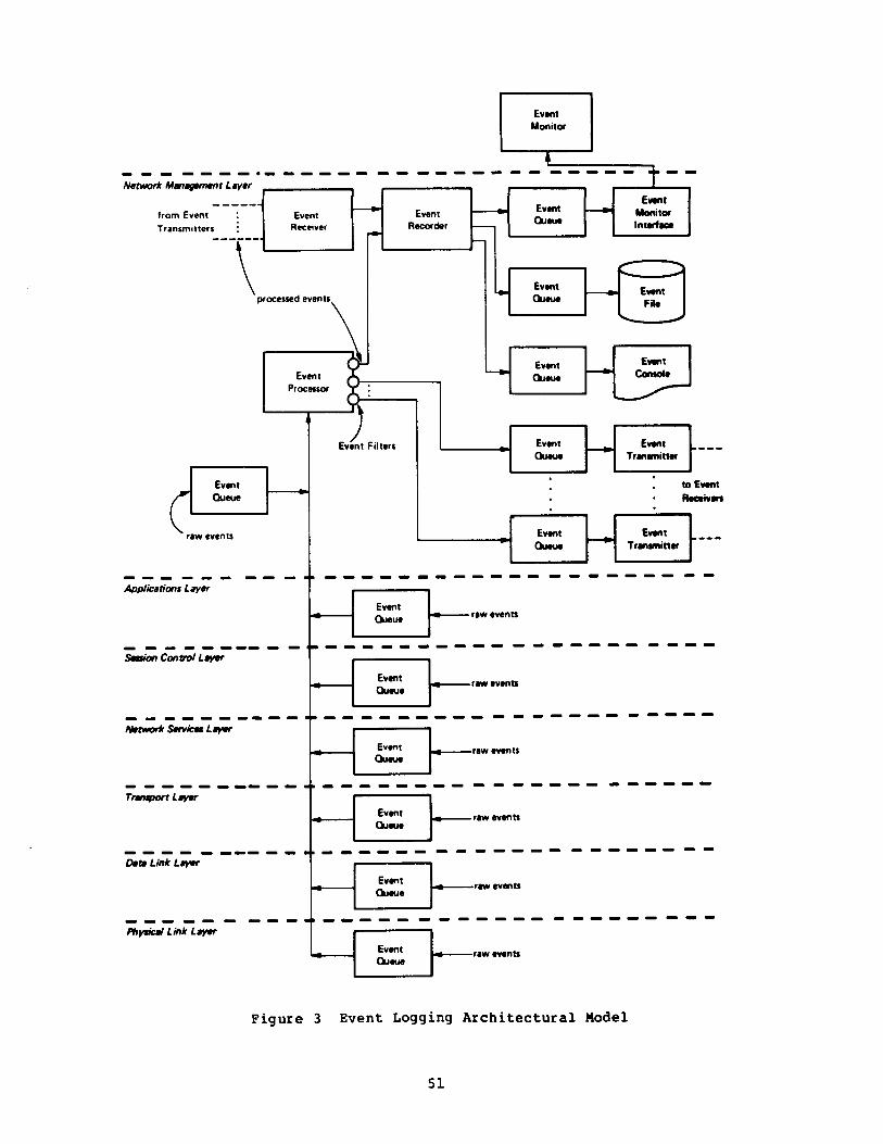
Network M a n 9 ~ ~ ~ 1 t Layer 1 I
------ - E m from Event : Event - E v n t Event Monitor
Receiver Recorder 7 Quw
Transmitters : I n t u f f * ------. -
\ ' A
Event Ennt processed events
- Queue -
Fit* '<Ã̂Ã ^
Event E v n t Event -
Queu* - Coniot*
Processor ri
raw events
...... 0 0 . c
Physical Link Lwfr
/ Event Filters
Event E-t ---- QIMUO ~rmtmittu
4 events
raw events Queue
Figure 3 Event Logging A r c h i t e c t u r a l Model

DECnet Event Logging is specified to meet the following goals:
Allow events to be logged to multiple sink nodes including the source node.
Allow an event to be logged to multiple logging sinks on any sink node.
Allow the definition of subsets of events for a sink on a node by event type and source node.
Include the following logging sinks: console, file, and monitor program.
Allow sharing of sinks between network event logging and local system event logging.
Minimize processing, memory, and network communication required to provide event logging.
Never block progress of network functions due to event logging performance limitations.
Minimize loss of event logging information due to resource limitations.
Record loss of event logging information due to resource limitations.
When required due to resource limitations, discard newer information (which can often be regained by checking current status) in favor of older.
Minimize impact of an overloaded sink on other sinks.
Standardize content and format of event logging information to the extent practical, providing a means of handling system specific information.
Allow independent control of sinks at sink node, including sink identification and sink state. Sink states include use of sink, non-use of sink, and temporary unavailability of sink.
4.1.5.1 Event Logger Components - As shown in Figure 3, the Event Logger consists of the following components, described in this section:
Event queue
Event processor
Event transmitter
0 Event receiver
Event recorder
0 Event console
Event file
Event monitor interface
Event monitor
5 2

Event queue -- There are several event queues (Figure 3). Each one buffers events to be recorded or transmitted, and controls the filling and emptying of the queue.
An event queue component has the following characteristics:
0 It buffers events on a first-in-first-out basis.
0 It fills a queue with one module; empties it with another.
0 It ensures that the filling module does not see an error when attempting to put an event on the queue.
Since event queues are not of infinite length, events must be lost. The filling module must record the loss of an event as an event, not as an error because of the third characteristic above. This event is called an "events-lost" event. An implementation requires the following algorithm at each event queue:
IF uueue is full Discard the event
ELSE IF this event would fill the aueue Discard the event IF last event on aueue is not 'events-lost*
Queue an 'events-lost" event (which fills the aueue) END IF
ELSE Queue the event
ENDIF
The event queue component handles "events-lost" events according to the following rules.
1. Consider such events "raw" for raw event queues and processed" for processed event queues.
2. Flag such events for the sink types of the lost events.
3. Time stamp such events with the time of first loss.
4. Filter. such events only if all events for the queue are also filtered.
Event Processor -- This component performs the following functions: 1. Scans the lower level event queues, collecting raw event
records.
2. Modifies raw events into processed events. Raw events contain the following fields:
Processed events contain the following fields:
DATA EVENT CODE ENTITY IDENTIFICATION
EVENT CODE
DATE AND TIME STAMP DATA
SOURCE NODE ID
SINK FLAGS
ENTITY NAME

3 . Compares the processed events with the event filters for each defined sink node, including the executor. Pollowing are the characteristics of the filters used to control event logging:
The event source node maintains all filters.
Each event sink node has a separate set of filters at the source node.
Each sink node set of filters contains a set of filters for each sink (monitor, file, or console).
Each sink node set of filters contains a set of global filters, one global filter for each event class. It also contains one or more specific filters, each for a particular entity within an event class.
Each filter contains one bit for each event type within the class. The bit reflects the event state. SET if the event is to be recorded, CLEAR if it is not.
The filtering algorithm sees first if there is a specific filter that applies to the event. If so, the algorithm uses the specific filter. If not, the algorithm uses the global filter for the class.
Commands from higher levels create and change filters using the EVENTS event-list option. When the specific filters match the global filter, the event processor deletes specific filters.
Although the filters are modeled in the event processor, in some implementations, to reduce information loss or for efficiency reasons, it may be necessary to filter raw events before they are put into the first event queue. A reasonable, low-overhead way to implement this is by providing an event on/off switch at the low level. The high level can turn this switch off if the event is filtered out by all possible filters. This avoids a complex filter data base or search at the low level, but prevents flooding the low level event queue with unwanted events.
4. Passes events not filtered out to the event recorder for the executor or to the appropriate event queue for other sink nodes.
Event Transmitter. Using a logical link, this component transmits event records from its queue to the event receiver on its associated sink node.
Event Receiver. This component receives event records over logical links from event transmitters in remote event source nodes. It then passes them to the event recorder.
Event Recorder. This module distributes events to the queues for the various event sinks according to the sink flags in the event records.
Event Console. This is the event logging sink at which human-readable copies of events are recorded.
Event File. This is the event logging sink at which machine-readable copies of events are recorded. To Network Management, it is an append-only file.

Event Monitor Interface. This interface makes events available to the Network Management Functions for reading by higher levels.
Event Monitor. This user layer module is an "operator's helper." It monitors incoming events by using the Network Management Access Routines and may take action based on what it has seen. Its specific responsibilities and algorithms are undefined for the near term.
4.1.5.2 Suggested Formats for Logging Data - Following are suggested text formats for logging data. System specific variations that do not obscure the necessary data or change standard terminology are allowed.
The date field in the output is optional if it is obvious from the context of the logging output.
Milliseconds can be used in the event time data if it is possible to do so. If not supported, this field will not be printed. It is possible for two times given the same second to be logged and printed out of order.
General format:
EVENT TYPE class.type[, event-text] FROM NODE address[ (node-name)]OCCURRED [dd-mon-yy]hh:nun:ss:[.uuu] [entity-type[entity-name]] [data]
For example:
Event tape 4 . 7 ~ Packet ageinst discard From node 27 (DOODAH)Ã occurred 9-FEB-79 13:55:38 Packet header = 2 23 91 20
Event tape 0 . 3 ~ Automatic l i n e service From node 19 <ELROND)à occurred 9-FEB-79 16:09:10.009 Line KDZ-0 - lÇ3 Service = Load9 Status = Reauested
Or, on a node that does not recognize the events:
Event tape 4 . 7 From node 279 occurred 9-FEE-79 13:55:38 Parameter #2 = 2 23 91 20
Event type 0.3 From node 1 9 ~ occurred 9-FEB-79 16:09:10.009 Line K D Z - O - ~ . ~ Ã Parameter #0 = 09 Parameter #1 = 0
4.2 Network Management Layer Operation
This section describes how Network Management operates with regard to each general function. Each function relates to a particular NICE message. Algorithms are given for most functions. There is also some user information in several of the descriptions, especially that concerning testing. Finally, there is a section explaining how NICE handles logical links. Appendix D lists status and error messages for NICE commands, and Section 4.3.12 explains the response message formats.

4.2.1 Down-line Load Operation - The down-line capability allows the loading of a memory image from a file to a target node. The file may reside at the executor node or at another node. Any node can initiate the load.
The requirements for a down-line load are as follows:
The target node must be directly connected to the executor node via a physical line. The executor node provides the line level access.
The target node must be running a minimal cooperating program (refer to the MOP functional specification). This program may be a primary loader from a bootstrap ROM. The down-line load procedure may actually involve loading a series of programs, each of which calls the next program until the operating system itself is loaded. The initial program request information determines the load file contents.
The direct access line involved must be in the ON or SERVICE state.
The executor must have access to the file. The location of the file can be either specified in the load request or looked up by the Local Network Management Function.
Local Network Management modules are used to obtain local files. Remote files are obtained via remote file access techniques. (Refer to the DAP functional specification.)
Figure 4, following, shows local and remote file access for a down-line load.
The executor must have access to a node data base, which can be either local or remote.
The target node must be able to recognize the trigger operation with software or hardware or must be triggered locally.

1. LOCAL FILE ACCESS
executor (V
f i
2. REMOTE FILE ACCESS
L o a d Link )APÃ
LEGEND: I MOP - Maintenance Operation Protocol FAL - File Access Listener
Figure 4 Down-line Load File Access Operation

Either the t a rge t or executor node (or a remote command node) can i n i t i a t e a down-line load. The t a r g e t node i n i t i a t e s the load by t r igger ing i t s boot ROM. The executor node i n i t i a t e s the load w i t h e i t he r a t r igger command or a load request . I f the executor does not have the i n i t i a l program request or the t a rge t does not respond t o the attempt t o load i t , the executor should t r igger the t a rge t .
Once the t a rge t is t r iggered , it requests the down-line load. The t a rge t node may be programmed t o request the load over the l i n e t ha t the t r igger message came. Or, the t a r g e t node could request the load from another executor. The Line Watcher a t the executor senses t h e f i r s t program request from the t a rge t node (usual ly a request for the secondary loader , described below). Or, if the operation was i n i t i a t e d by a Network Management load request , the program request is received a s a response t o t h a t request . Figure 5 , following, shows the down-line load request operation.

1. TARGET-INITIATED REQUEST
MOP
\ 1 Function I
2. OPERATOR-INITIATED REQUEST FROM A REMOTE COMMAND NODE
^X I Network 1 \
LEGEND: I MOP - Maintenance Operation Protocol NICE - Network Information and Control Exchange NCP - Network Control Program
Figure 5 Down-1 i n e Load Request Operation

The executor proceeds with the load according to the options in the initial request.
Several fields in the NICE request down-line load message may be either furnished as overrides or defaulted to the values in the node data base. Any information left to default is first obtained from the data base.
The executor identifies the target node by address, name, or line. The name and address parameters may be supplied as overrides to those in the data bases. The address or line identification key into the node data base. If line is used, then address is obtained from the data base entry. If a target is identified by name, then address is determined by normal name to address mapping and used to key into the data base.
The address the target is to have is always sent to the target during the down line load request operation. This target address is either obtained from the node data base or supplied as an override.
The name the target is to have, if any, is either supplied with the request as an override or obtained by normal address-to-name mapping.
Host identification follows similar rules to target identification. The host node address must be sent to the target. If both name and address are not supplied, address is obtained from the node data base. Name, if any, is obtained by normal address-to-name mapping, if not supplied.
The executor controls the process of loading the requested programs until the operating system is loaded. The executor is responsible for understanding the service protocol (for example, MOP) from and to the target.
The first program to run in the target node, called the primary loader, is typically loaded directly from its own bootstrap ROM. It then requests, over the communications line, the next program in the sequence. This program, the secondary loader, may have certain restrictions on the way it is loaded, depending on the capabilities of the primary loader. This process may extend through a tertiary loader. The final program to be loaded is defined as the operating system, although it does not necessarily have to be capable of being a network node. Within a single down-line load process (possibly including "loader loads") each program loaded is expected to request another, except for the operating system, which does not.
When the down-line load has been completed (in other words, the operating system successfully loaded) or aborted due to an error, the executor sends the proper response back to the command node to finish up the process.
The content of the load image file is specified in Appendix C.
The algorithm for handling the down-line load is as follows:
Call Line Service Function to open line for load Perform load callina Line Service Function to transmit and receive Call Line Service Function to close line
4.2.2 Up-line Dump Operation - The up-line dump capability of the Network Management layer allows a system to dump its memory to a file on a network node.

The requirements for such a dump correspond with those for a down-line load :
Â
Â
Â
Â
The system being dumped must be connected to a network node (executor) by a specific physical line.
The system being dumped must run a minimal cooperative program that can communicate over the line with the executor. The protocol used is implementation-dependent (refer to the MOP specification).
If the executor determines that the program is not there, then executor must supply the program. This is the secondary dumper.
The line used must be in the ON or SERVICE state and returned afterwards to its original state.
The executor must have access to the file receiving the dump. If the file is remote, the executor transfers the data using remote file access routines. (Refer to the DAP Functional Specification.)
The system to be dumped can indicate that it is capable of being dumped. In this case, the Line Watcher at the executor node senses the possibility of a dump and can pass a dump request to the Local Network Management Functions at the executor node. Alternatively, the executor or a remote command node can initiate the dump with an NCP DUMP command. In this case, the executor node's Local Network Management Functions receive the request from the Network Management Access Routines or the Network Management Listener.
The Local Network Management Functions proceed according to the options in the request. Any required information that has been left to default is first obtained from the node data base. The Local Network Management Functions then accomplish the dump using the system-dependent service protocol (for example, MOP), and the local operating system's file system or network remote file transfer facilities. If the remote system does not respond, the executor can trigger the remote system and load a secondary dumping program.
In cases where the dump was not initiated by the target node, when the requested memory has been dumped to a file or the dump has been aborted, the executor sends an appropriate response back to the node requesting the operation.
The content of the dump file is specified in Appendix C.
The algorithm for performing the up-line dump is as follows:
C a l l Line S e r v i c e Funct ion t o open l i n e f o r dump Perform ~ ' J ~ I F ' c a l l i n 3 Line S e r v i c e Funct,ion to transmit and r e c e i v e C a l l L.ine S e r v i c e F u r ~ c t i o r ~ t o c l o s e l i n e
4.2.3 Trigger Bootstrap Operation - The trigger bootstrap capability of the Network Management layer allows remote control of an operating system's restart capability. Since a system being booted is not necessarily a fully functional network node, the operation must be performed over a specific physical line (specified by a line-identification). The node on the network side of the line is called the executor node.

The NCP TRIGGER command can initiate the trigger bootstrap function via the Network Management Listener and/or the Network Management Access Routines. The Local Network Management Functions at the executor node receive the request.
When the Local Network Management Functions receive a NICE trigger bootstrap request, they proceed according to the options in the request. Any required information which has been left to default is obtained from the node data base.
The physical line being used must be in the ON or SERVICE state at the executor node's end. The executor uses the system-dependent service protocol (for example, MOP) to perform the operation.
When the operation is complete, the executor sends its response to the command node.
Once the target node is triggered, it will then load itself in whatever manner its bootstrap ROM is programmed to operate. This could include requesting a down-line load either from the executor that just triggered it or some other. The target node could load itself from its own mass storage.
The algorithm for implementing the trigger bootstrap is as follows:
Call Line Service function to open line for triaaer Perform trisisier~ callina line service to transmit Call Line Service function to close line
4.2.4 Loop Test Operation - There are two types of loop tests, node level and line level. Both types are loopback tests that loop a standard test block a specified number of times.
If either test fails, the response explains the failure. If the test fails because the test message was too long, the error return is "invalid parameter value, length" (Appendix D) and the test data field of the error message contains the maximum length of the loop test data, exclusive of test data overhead. If the test fails for any other reason, the test data field contains the number of messages that had not been looped when the test was declared a failure.
The unlooped count need not be returned for success or for errors that occur before looping can begin (for example, connect errors, command message format, or content errors). The only exception to this is the case that the value of the length parameter is too large, since this requires a return of the maximum length.
4.2.4.1 Node Level Testing - There are two general categories of node level tests (shown in Figures 6 and 7, following). Both use normal traffic that requires logical links. Both have variations that use the Loopback Mirror and NCP LOOP NODE commands. The difference is that the first type uses what might be called "normal" communication, while the second type sets up a loop node name established with the NCP SET NODE LINE command.
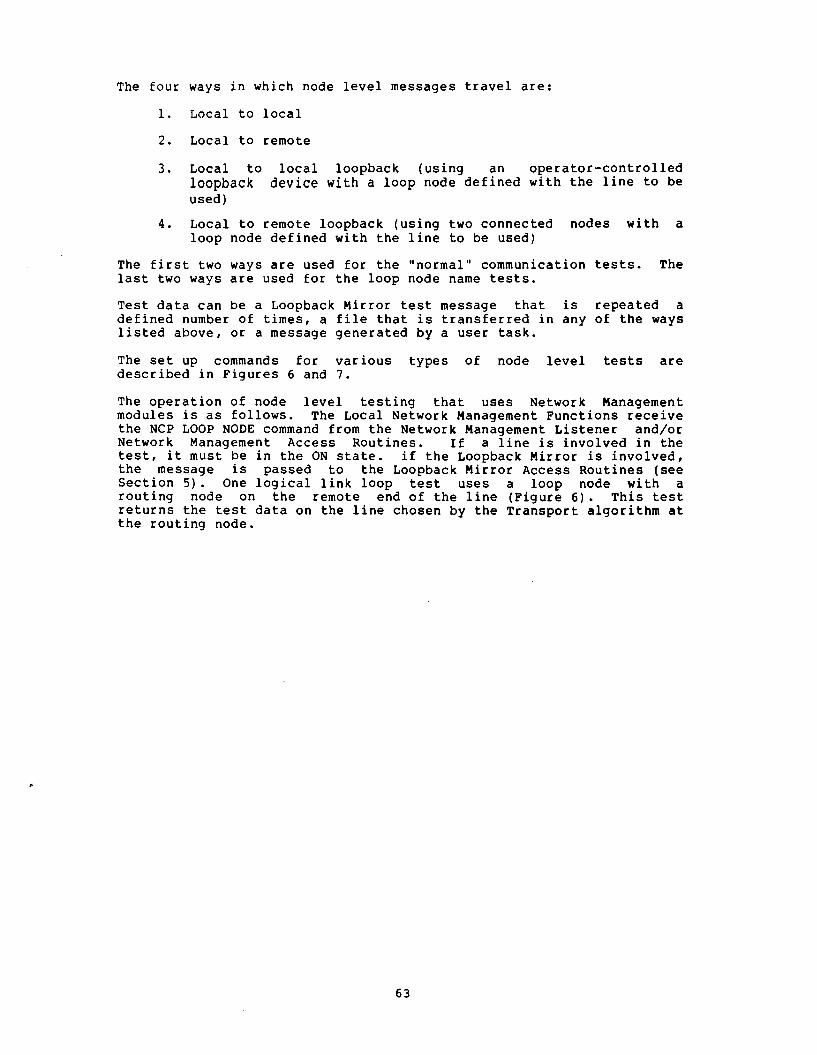
The four ways in which node level messages travel are:
1. Local to local
2. Local to remote
3. Local to local loopback (using an operator-controlled loopback device with a loop node defined with the line to be used )
4. Local to remote loopback (using two connected nodes with a loop node defined with the line to be used)
The first two ways are used for the "normal" communication tests. The last two ways are used for the loop node name tests.
Test data can be a Loopback Mirror test message that is repeated a defined number of times, a file that is transferred in any of the ways listed above, or a message generated by a user task.
The set up commands for various types of node level tests are described in Figures 6 and 7.
The operation of node level testing that uses Network Management modules is as follows. The Local Network Management Functions receive the NCP LOOP NODE command from the Network Management Listener and/or Network Management Access Routines. If a line is involved in the test, it must be in the ON state. if the Loopback Mirror is involved, the message is passed to the Loopback Mirror Access Routines (see Section 5). One logical link loop test uses a loop node with a routing node on the remote end of the line (Figure 6). This test returns the test data on the line chosen by the Transport algorithm at the routing node.

A. Localto-LooobKh Node Tat, Smote Node. uung t i l t à m t d m . with 0 softwf controltfj IoopbKk u u b i l i t y
SET LINE line id CONTROLLER LOOPBACK SET NODE FISHY LINE line id ITranilcr hie toilronn FISHY1
NODE BOB
r i
, rf
Sewon Control I ' /^ I f /,
Network I I // 1
C L o c i toLoopbxck Node Tmt. Two Nodes. using uwr task
SET NODE FISHY LINE low id llnvoke u r r Ink using BOB and FISHY1
NODE BOB
Uwr Talk
Network Management
Mdtwwk Application
Session Control I 1
1 Network 1 1 1
Date Link I Physical Link \ 1
1 , 1 I
Nod* T i t . Single Nod*, uung loopback mirror and w i t -. and a manually MI
loopback device
SET NOOE FISHY LINE I-M id LOOP NOOE FISHY
NODE BOB
User Modules
Network 1 Access Routines 1 Management 1 Local Network Managimm unction]
Session CWWOI /;' -/S-'- Network Services
Data Link
Physical Link
NODE TONY
uwr M o d u l i
Network
Seinon Conl,ol
Network I
D. L o d t o L o o p b w k Node Test. Two Nodn. uung loopback mirror and f t mn-
SET NODE FISHY LINE lux-id LOOP NODE FISHY
F i g u r e 6 Examples o f Node Level T e s t i n g Using a Loopback Node Name w i t h and w i t h o u t t h e Loopback Mirror
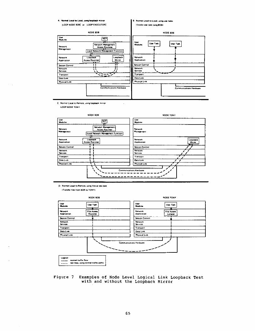
A N w m d Laal.lo.Local, uung m~rrm
!LOOP NOOE BOB! or {LOOP EXECUTORI I B Normal LocaltoLocal, usoq uwr t a f t i
Invoke user talk uung BOB)
NODE BOB I NODE BOB
" E-̂ yq T I
I
Network Application
1 + ~ession Control : Nçwor
L \ I
Services 'v. ---- ,,' Tfanspoft
Data Link
Physical Link
Communicationi Hardware L l Communications Hardware L- C Normal Local IO Remote using loopback mirror
LOOP NOOE TONY
NODE BOB NODE TONY
Network Access Routines Network Mmagtment Management
-- Network L O O P ~ ~ ~ Network LoopbKh Application Access Routines Application M ~ r n x *. Slsion Control I i Session Control / ,/ Network ! 1 Network a'" /
0. Normal LocaltoRemote. uunq files à t à § data
(Transfer files from BOB to TONY1
Services ! I Tramport 1 ,
I , Oau Link à i Physical Link I \
NODE BOB
Services /' /- Transport /'
/ / Data Link / / Phyncal Link / a'
NOOE TONY
Communicationi Hardware
I L w n d . - normal traffic flow - - f i t data, using normal traffic paths
Lhf Uwr Taft Modulo
A - Nelwork File Accç Application R o u t i n i
Session Control T N ~ t w o r k I S e r v i c i
Transport 1 D a n Link
Phyncal Link I
F igure 7 Examples o f Node Level Logical Link Loopback T e s t with and without the Loopback Mirror
0 I /
Communication! Hardware ^ ¥"in. ,' -- -------- - - M ~
Uwr M o d u l f
U n Task a -
Network Application
File Acceu Lutentr
Session Control 4 Network Services I Transport 1
Data Link I
Physical Link I

4.2.4.2 Data Link Testing - Line level testing requires a direct interface between the Line Service Function and the Data Link layer. Figure 8 at the end of this section shows two types of line level tests:
1. Direct line loopback, hardware looped
2. Direct line loopback, software looped
Line loopback requires the use of line service software (for example, MOP), with the line to be tested in the ON or SERVICE state.
The hardware-looped option requires an operator-controlled loopback controller, a modem set to loopback mode, a ROM with loopback capabilities at the remote end, or some other equivalent operation. It is recommended that the operator turn off the line, reconfigure the hardware, and then turn the line back on. Alternatively, the operator may leave the line in the ON state, and any resulting synchronization problem will be logged as an error.
The algorithm for the active loop test is as follows:
Set not done Call Line Service Functions to open line for active loop WHILE not done
Call Line Service Function to transmit loopback. data message Call Line Service Function to receive messaae IF error OR count exhausted OR message is not loop data or looped data OR received data does not match sent data
Set done END IF
ENDWHILE Call L..ine Service Function to close line

[SET LINE lilf-id STATE OFF1 Ilir à ON or SERVICE IUÇ
SET LINE Inn id STATE ON/SERVICE" SET LINE 1-4 CONTROLLER LOOPBACK I LOOP LINE IIW id \ LOOT LINE 1-4 I
I Lirr %,a Functions . . J I
Dau Link
Direct Lam Loowck, 10- loo&. low m ON or SERVICE in-"
EXKU~W Nod* LOOP LINE lincid
A
D<U I q Link I I nivucd I I
Figure 8 Physical Link Loopback Tests and Command Sequences Effecting Them
4.2.5 Change Parameter Operation - When a NICE change parameter request is received, the specified parameters are changed, usually by interfacing with the local operating system. An appropriate response is then returned to the requestor. The options of the change parameter request indicate the desired operation (either specifying a different value or removing the value) and the entity it relates to. The operation can be done either for volatile or permanent parameters.
The request may contain zero or more parameters. If there are none, the operation applies to the entire entity entry (in other words, the NCP ALL parameter). All parameters in the message should be checked before any are changed in the data base. If one parameter fails the check, then the operation should fail. A single response indicates success or failure for single-entity operations.

A ch case f a i l no more
ange parameter request may apply t o a group of e n t i t i e s . In t h i s , success or f a i l u r e is individual . The e n t i r e request does not i f a s i ng l e e n t i t y request f a i l s . An i n i t i a l f a i l re turn implies
fu r the r responses a r e coming. A spec ia l success re turn ind ica tes responses w i l l follow, one for each e n t i t y in the group.
Changing the l i n e s t a t e requires the following capab i l i t i e s :
For operator:
a Set l i n e s t a t e t o OFF
Set l i n e s t a t e t o ON
0 Set l i n e s t a t e t o SERVICE
For the Line Watcher:
Set l i n e s t a t e t o ON-AUTOSERVICE
Reset l i n e s t a t e from ON-AUTOSERVICE
A l l of the algorithms imply recording the l i n e s t a t e i f they succeed. The l i n e s t a t e algorithms follow.
Set l i n e s t a t e t o OFF:
Call Transport to set line state to off Call Line Service Function to set line state to off
Set l i n e s t a t e t o ON:
Call Line Service Function to set line state to passive IF success
Call Transport to set line state to on ELSE
Fai 1 ENDIF
Set l i n e s t a t e t o SERVICE:
Call Line Service Function to set line state to closed IF success
Call Transport to set line state to off ELSE
Fai 1 ENDIF
Set l i n e s t a t e t o ON-AUTOSERVICE:
IF line state is ON Perform alaorithi to set line state to service
ELSE Fai 1
ENDIF
Reset l i n e s t a t e from ON-AUTOSERVICE:
If line state is ON-AUTOSERVICE: Perform aldorithi to set line state to on
ENDIF

4.2.6 Read Information Operation - When a read information request is received, a response is returned, followed by the requested data in the form of standard Network Management data blocks (Appendix A). The data may be obtained either from within the Local Network Management Function itself or by interfacing with the system as appropriate.
The many restrictions and special situations relating to reading specific parameters or counters are described in Appendix A. Additional information is in Section 3 . 3 . 8 (SHOW command).
A fail return in the first response implies no further responses are coming. A special success return indicates the command message was accepted and more will follow.
4.2.7 Zero Counters Operation - When a zero counters request is received, the appropriate counters are cleared by interfacing with the local operating system. An appropriate response is then returned to the requestor.
If a read and zero was requested, the counters are returned as if a read information had been requested.
A fail return on the first response implies no further responses are coming. Success is a single return for single-entity operations. For multiple-entity operations, success is a special success return implying further responses.
4.2.8 NICE Logical Link Handling - This section describes the logical link algorithms that Network Management uses when sending NICE messages. The version data formats are in Section 4.3.12. The determination that a received version number is acceptable is always the responsibility of the higher version software, whether it is the command source or the listener.
The recommended buffer size for NICE messages is 300 bytes.
The Network Management Listener algorithm follows:
Receive connect reouest (Optionally) Determine privilege level based on access control IF resources available and received version number OK
Send connect accept with version number in accept data WHILE connected (see Noter below)
Receive comniand message IF message received
Process command message according to command and privilege Send response içiessaae<s
ENDIF ENDWHILE
ELSE IF received version number not OK
Send connect reject with version skew reason in reject data ELSE
Send connect reject END I F
ENDIF

NOTE
The algorithms used for connections is implementation dependent. For example, connections can be maintained permanently, only while the executor is set, timed-out, or one per command.
The Network Management command source algorithm follows:
Send connect reouest with version number in connect data IF connect accepted
IF received version number OK WHILE desired
Send command message Receive response message<s>
ENDWHILE ENDIF Disconnect link
ELSE IF connect rejected by listener
IF reject data indicates version skew Failure due to version skew
ELSE Failure due to listener resources
ENDIF ELSE
Failure due to network connect problem ENDIF
END IF
4.2.9 Algorithm for Accepting Version Numbers - A version number consists of three parts -- version, ECO (Engineering Change Order), and user ECO (Section 4.3.12). In general, another version is acceptable if it is greater than or equal to this version. If less than this version, it is optionally acceptable as determined by product requirements.
When comparing two version numbers, compare the second parts only if the first parts are equal, and so on.
4.2.10 Return Code Handling - Use the following return code handling algorithm to call the Network Management access routines:
Initiate function IF return code = more
WHILE return code < > done Perform next operation Process success/failure
ENDWHILE ELSE
Process success/failure END IF
Note that an initiate call starts the function, and an operate call performs the function (one entity at a time in the case of plural entities).

4 . 3 Network Management Layer Messages
This section describes the NICE and Event Logging Messages, NICE response message format, and NICE connect and accept data format.
NICE is a command-response protocol. Because the Network Management layer is built on top of the Network Services and Data Link layers, which provide logical links that guarantee sequential and error-free data delivery, NICE does not have to handle error recovery.
In the message descriptions that follow, any unused bits or bytes are to be reserved and set to zero to allow compatibility with future implementations. Conditions such as non-zero reserved areas and unrecognized codes or unused bytes at the end of a field or message should be treated as errors, and no operation should be performed other than an appropriate error response.
The entire message should be parsed and checked for validity before any operation is performed.
4.3.1 NICE Function Codes - The Phase I11 NICE protocol performs the following message functions. The last one commands, not specified in this document.
is for system specific
Function CODE
15 16 17 18 19 2 0 2 1 2 2
NICE Function
Request down-line load Request up-line dump Trigger bootstrap Test Change parameter Read information Zero counters System-specific function
4 . 3 . 2 Message and Data Type Format Notation - The Network Management message format and data type descriptions use the following notation.
FIELD (LENGTH) : CODING = Description of field
where :
FIELD Is the name of the field being described
LENGTH Is the length of the field as:
1. A number meaning number of 8-bit bytes.
2 . A number followed by a "B" meaning number of bits.
3. The letters "EX-no' meaning extensible field with n being a number meaning the maximum length in 8-bit bytes. If no number is specified the length is limited only by the maximum NICE message. Extensible fields are variable in length consisting of 8-bit bytes, where the high-order bit of each byte denotes whether the next byte is part of the same field. The -1 means the next byte is part of this field while a 0 denotes the last byte.

Extensible fields can be binary or bit map; if binary, then 7 bits from each byte are concatenated into a single binary field; if bit map, then 7 bits from each byte are used independently as information bits. The bit definitions define the information bits after removing extension bits and compressing the bytes.
4. The letters "I-n" meaning image field with n being a number which i s the maximum l e n g t h i n 8 - b i t b y t e s of the image. The image is preceded by a 1-byte count of the length of the remainder of the field. Image fields are variable length and may be null (count-0). All 8 bits of each byte are used as information bits. The meaning and interpretation of each image field is defined with that specific field.
5. The character "*" meaning remainder of message. A number following the asterisk indicates the minimum field length in bytes.
COD I NG Is the representation type used.
where :
A = 7-bit ASCII
6 = Binary
BM = Bit Map (where each bit or group of bits has independent meaning)
C = Constant
NOTES
1. If length and coding are omitted, FIELD represents a generic field with a number of subfields specified in the descriptions.
2. Any bit or field which is stated to be "reserved" shall be zero unless otherwise specified. Any bit or field not described is reserved.
3. All numeric values in this document are shown in decimal representation unless otherwise noted.
4. All fields are presented to the physical link protocol least significant byte first. In an ASCII field, the leftmost character is in the low-order byte.
5 . Bytes in this document are numbered with bit 0 the rightmost (low-order, least-significant) bit, and bit 7 the leftmost (high-order, most-significant) bit. Fields and bytes of other lengths are numbered similarly.
6. Corresponding data type format notation used in Tables 6, 8, and Appendix F is described at the beginning of Appendix A.

where:
4.3.3 Request Down-line Load Message Format
FUNCTION CODE (1) : B = 15
FUNCTION CODE
NODE
NODE OPTION
OPTION (1) BM IS one of the following options:
LINE
Option bits
LINE
Value/Meaning 1
Is the line identification in line id format (see Appendix A). Plural lines options not allowed. Present only if option bit 0 = 1.
PARAMETER ENTRIES
0
PARAMETER ENTRIES are zero or more of PARAMETER ENTRY consisting of:
m
0 = Identify target by node-id. 1 = Identify target by line-id.
where:
Is the target node identification in node-id format (see Appendix A) as key into defaults data base (present only if option bit 0 = 0). Plural nodes options are not allowed.
DATA ID (2) : B Is the parameter type number (see note below and Appendix A)
DATA Is the parameter data (Appendix A).
NOTE
The parameters allowed are the following node parameters:
ADDRESS CPU HOST LOAD FILE NAME SECONDARY LOADER SERVICE DEVICE SERVICE LINE (allowed only
if bit 0 = 0) SERVICE PASSWORD SOFTWARE IDENTIFICATION SOFTWARE TYPE TERTIARY LOADER

4.3.4 Request Up-line Dump Message Format I , I I I I 1 FUNCTION 1 OPTION 1 NODE 1 L I N E 1 PARAMETER 1
CODE ENTRIES
where:
FUNCTION CODE ( I ) : B = 16
OPTION (1) : BM Is one of t h e fol lowing op t ions :
1 Option b i t s 1 Value/Meaning I
NODE
L I N E
I d e n t i f i e s t h e node t o be dumped ( p r e s e n t on ly i f op t ion b i t 0 = 0 ) . Format is def ined i n Sec t ion A.3.
0
S p e c i f i e s t h e l i n e over which t o dump ( p r e s e n t on ly i f op t ion b i t 0 = 1). Format is de f ined i n Sec t ion A . I .
0 = I d e n t i f y t a r g e t by node-id. 1 = I d e n t i f y t a r g e t by l i ne - id .
PARAMETER ENTRIES a r e zero or more of PARAMETER ENTRY c o n s i s t i n g o f :
where:
DATA I D ( 2 ) : B Is t h e parameter type number (see no te below and Appendix A )
DATA Is t h e parameter d a t a (Appendix A ) .
NOTE
The parameters a r e s e l e c t e d from t h e node parameters . Only c e r t a i n parameters a r e allowed i n t h e dump message . They a r e :
DUMP ADDRESS DUMP COUNT DUMP FILE SECONDARY DUMPER SERVICE L I N E (allowed only
i f op t ion b i t 0 = 0) SERVICE PASSWORD

4.3.5 Trigger Bootstrap Message Format
where:
FUNCTION CODE
FUNCTION CODE (I) : B = 17
OPTION (1) : BM Is one of the following options:
Option bits Value/Meaning 1
OPTION
NODE
LINE
NODE
Identifies the line over which to trigger the boot (present only if option bit 0 = 1). The format is defined in Section A.1.
0
PARAMETER ENTRIES are zero or more of PARAMETER ENTRY consisting of:
LINE
0 = Identify target by node-id. 1 = Identify target by line-id.
where :
PARAMETER ENTRIES
Identifies the node to trigger boot on (present only if option bit 0 = 0). The format is defined in Section A.3.
DATA ID (2) : B Is the parameter type number (see note below and Appendix A)
DATA Is the parameter data (Appendix A ) .
NOTE
The parameters are selected from the node parameters. Only certain parameters are allowed in the trigger message. They a c e :
SERVICE LINE (allowed only if option bit 0 = 0)
SERVICE PASSWORD
4.3.6 Test Message Format
PARAMETER ENTRIES
FUNCTION CODE
OPTION PASSWORD NODE ACCOUNTING USER LINE

where:
FUNCTION CODE (I): B = 18
OPTION (1) : BM Is one of the following options:
Option bits
I
If node type
Value/Meaning
0 = Node type loop test 1 = Line type loop test
loop test :
0 = Default access control 1 = Access control included
For node type loop tests only (option 0), four parameters are as follows:
NODE Identifies the node to loopback the test block in node-id format (Section A.3). Plural node options are not allowed.
USER (1-39) : A Is the user-id to use when connecting to node. Present only if option bit 7 = 1.
PASSWORD (1-39): A Is the password to use when connecting to node. Present only if option bit 7 = 1.
ACCOUNTING (I-39):A Is the accounting information to use when connecting to node. Present only if option bit 7 = 1.
For line tests only (option l), one parameter is as follows:
LINE Identifies the line to send the test on in line-id format (Section A.1). Plural lines options not allowed.
PARAMETER ENTRIES Are zero or more of PARAMETER ENTRY, consisting of:
1 DATA 14 DATA 1 where:
DATA ID (2) : B Is the parameter type number (Appendix A) .
DATA Is the parameter data (Appendix A).
NOTE
The parameters are selected from the node parameters. Only certain parameters are allowed in the test message. They are:
LOOP COUNT LOOP LENGTH LOOP WITH

4 . 3 . 7 Change Parameter Message Format
IFUNCTION OPTION ENTITY PARAMETER1 CODE 1 1 ID 1 ENTRIES
where:
FUNCTION CODE (1): B = 19
OPTION (1) : BM IS one of the following options:
1 Bits 1 Meaning
1 ' I 0 = Change volatile parameters.
1 6 I 0 = Setldefine parameters.
1 1 1 = Clear/purge parameters.
1 0-1 1 Entity type (~ppendix A).
ENTITY ID Identifies the particular entity (Appendix A).
PARAMETER ENTRIES Are zero or more of PARAMETER ENTRY consisting of:
[ E K q T q where:
DATA ID ( 2 ) : B
DATA
Parameter tYPe number (Appendix A).
4 . 3 . 8 Read Information Message Format
New value according to DATA ID (Appendix A). Present only if option bit 6 = 0.
- FUNCTION
CODE
where:
FUNCTION CODE (1): B = 20
OPTION ENTITY ID

0 = Read volatile parameter 1 = Read permanent parameter
OPTION (1) : BM Is one of the following options:
I 4-6 I Information type as follows;
Bits
0 = Summary 1 = Status 2 = Characteristics 3 = Counters 4 = Events
Meaning
ENTITY ID Identifies the particular entity (Appendix A).
0-1 Entity type (Appendix A) .
where:
FUNCTION CODE (1) :
OPTION (1): BM
4 . 3 . 9 Zero Counters Message Format
Is one of the following options:
FUNCTION CODE
ENTITY ID
OPTION ENTITY ID
Ei ts
7
Meaning
1 = Read and zero 0 = Zero only
0-1
where:
Entity type (Appendix A). (line or node only)
4.3.10 NICE System Specific Message Format
FUNCTION CODE (1) : B = 2 2
Identifies the particular entity, if required (Appendix A).
FUNCTION CODE
SYSTEM TYPE (1) : B Represents the type of operating system command to which command is specific.
1 value 1 system 1
SYSTEM TYPE
REMAINDER
REMAINDER ( * ) : B Consists of data, depending on system specific requirements.
7 8
1 2 3 4
RSTS RSX family TOPS-20 VMS

RETURN CODE (1) : B Is one of t h e s t anda rd NICE r e t u r n codes (Appendix Dl
4.3.11 NICE Response Message Format
ERROR D E T A I L ( 2 ) :B Is more d e t a i l e d e r r o r in format ion according t o t h e e r r o r code ( e .g . , a parameter t y p e ) . Zero i f no t a p p l i c a b l e . I f a p p l i c a b l e bu t no t a v a i l a b l e , i t s va lue is 65,535 ( a l l b i t s s e t ) . I n t h i s c a s e i t is not p r i n t e d .
ERROR MESSAGE Is a system dependent e r r o r message t h a t may be (1-72) : A ou tpu t i n a d d i t i o n t o t h e s t anda rd e r r o r message.
[ENTITY I D ] I d e n t i f i e s a p a r t i c u l a r e n t i t y (Appendix A) i f ope ra t i on is on p l u r a l e n t i t i e s , o r o p e r a t i o n is read informat ion o r read and zero coun te r s . I f t h e e n t i t y is t h e executor node, b i t 7 of t h e name l eng th is s e t .
4
where :
ENTITY I D
ERROR MESSAGE
RETURN CODE
[TEST DATA] ( 2 ) : B Is t h e in format ion r e s u l t i n g from a test o p e r a t i o n (Tes t message o n l y ) . Th i s is o n l y r equ i r ed i f a t e s t f a i l e d and i f d a t a is r e l e v a n t . Sec t ion 4.2.4 e x p l a i n s c o n t e n t s .
ERROR DETAIL
[DATA BLOCK] Is one of t h e d a t a b locks desc r ibed i n Appendix A ( f o r read informat ion message o r read and zero message) .
TEST DATA
I f a response message is s h o r t t e rmina ted a f t e r any f i e l d , t h e e x i s t i n g f i e l d s may s t i l l be i n t e r p r e t e d accord ing t o s t anda rd format. Th i s means, f o r example, t h a t a s i n g l e by t e r e t u r n is t o be i n t e r p r e t e d a s a r e t u r n code.
1 DATA BLOCK
Responses t o messages no t noted a s excep t ions above a r e s i n g l e responses i n d i c a t i n g r e t u r n code, e r r o r d e t a i l , and e r r o r message.
A succes s response t o a r eques t f o r p l u r a l e n t i t i e s is ind i ca t ed by a r e t u r n code of 2 , followed by a s e p a r a t e response message for each e n t i t y . Each of t h e s e messages c o n t a i n s t h e b a s i c response data ( r e t u r n code, e r r o r d e t a i l , and e r r o r message) and t h e e n t i t y i d . A r e t u r n code of -128 i n d i c a t e s t h e end of m u l t i p l e responses .
4.3.12 NICE Connect and Accept Data Formats - The f i r s t t h r e e b y t e s of t h e connect accep t d a t a a r e :
where :
VERSION (1) : B Is t h e v e r s i o n number
DEC ECO (1) : B Is t h e DIGITAL ECO number
USER ECO (1) : B Is t h e user ECO number

4.3 .13 E v e n t Message B i n a r y Data Format - T h i s s e c t i o n d e s c r i b e s t h e g e n e r a l i z e d b i n a r y f o r m a t o f e v e n t d a t a . I t a p p l i e s t o messages on l o g i c a l l i n k s a n d , a s much a s p o s s i b l e , t o f i l e s .
The b u f f e r s i z e f o r e v e n t messages i s 200 b y t e s .
The f o r m a t o f a n e v e n t l o g g i n g message is:
where :
FUNCTION CODE (1) : B = 1, meaning e v e n t l o g
EVENT DATA
FUNCTION CODE
SINK FLAGS (1) : BM Are f l a g s i n d i c a t i n g which s i n k s a r e t o r e c e i v e a copy o f t h i s e v e n t , one b i t p e r s i n k . The b i t a s s i g n m e n t s a re : f I t
Conso le F i l e Moni tor
SINK FLAGS
EVENT CODE ( 2 ) : BM I d e n t i f i e s t h e s p e c i f i c e v e n t a s f o l l o w s :
Meaning
Even t t y p e 6-14 Even t c lass
EVENT TIME
EVENT CODE
Is t h e s o u r c e node d a t e and time o f e v e n t p r o c e s s i n g . C o n s i s t s o f :
HALF DAY
where :
EVENT TIME
JULIAN HALF DAY ( 2 ) : B = Number o f h a l f d a y s s i n c e 1 J a n 1977 and b e f o r e 9 Nov 2621 (0-32767) . For example , t h e morning o f J a n 1, 1977 is 0.
SECOND ( 2 ) : B = Second w i t h i n c u r r e n t h a l f d a y (0 -43199) .
SOURCE NODE
MILLISECOND ( 2 ) : B = M i l l i s e c o n d w i t h i n c u r r e n t s econd (0 -999) . I f n o t s u p p o r t e d , h i g h o r d e r b i t is se t , r ema inde r a r e c l ea r , and f i e l d is n o t p r i n t e d when f o r m a t t e d f o r o u t p u t .
EVENT ENTITY

SOURCE NODE
EVENT ENTITY
Identifies the source node. It consists of:
where :
NODE ADDRESS (2) : B = Node address (see Section A. 3) .
NODE NAME (1-6) : A = Node nameI 0 lengthI if none.
Identifies the entity involved in the event, as applicable. Consists of:
ENTITY ENTITY -1 where:
ENTITY TYPE (1) : B Represents the type of entityI as follows:
1 Value 1 Entity Type 1 ENTITY ID Field 1
ENTITY ID
- 1 0 1
Identifies the entity. Depends on typeI defined below.
where:
none Line Node
LINE ID (1-16) : A Identifies a 1 ine entity.
none LINE ID NODE ID
NODE ID Identifies a node entityI same form as for SOURCE NODE.
EVENT DATA ( * ) : B Is event specific data, zero or more data entries as defined for NICE data blocks, parameter types according to event class.

5.0 APPLICATION LAYER NETWORK MANAGEMENT FUNCTIONS
The only Network Management function specified for the application layer is the loopback mirror.
5.1 Loopback Mirror Modules
The Loopback Mirror service tests logical links either between nodes or within a single node. It consists of an access interface -- the Loopback Access Routine; service routines -- the Loopback Mirror; and a simple protocol -- the Logical Loopback Protocol.
5.2 Loopback Mirror Operation
When the Loopback Mirror accepts a connect, it returns its maximum data size in the accept data. This is the amount of data it can handle, not counting the function code.
When a Logical Loopback message is received, it is changed into the appropriate response message and returned to the user (Figure 7, Section 4). The Loopback Mirror continues to repeat all traffic offered. The initiator of the link disconnects it.
5.3 Logical Loopback Message
Section 4.3.2 describes message format notation.
If the function code is not valid, or the message is too long, the failure code is returned.
5.3.1 Connect Accept Data Format
-1 where :
MAXIMUM DATA (2) : B Is the maximum length, in bytes, that the Loopback Mirror can loop.
5.3.2 Command Message Format
where :
FUNCTION CODE (1) : B = 0
DATA ( * ) : B Is the data to loop.

5 . 3 . 3 Response Message
where:
RETURN CODE (1) : B I n d i c a t e s S u c c e s s (1 ) or F a i l u r e ( - 1 ) .
DATA ( * ) : B I s t h e d a t a a s r e c e i v e d , i f s u c c e s s .
APPENDIX A
NETWORK MANAGEMENT ENTITIES, PARAMETERS, AND COUNTERS: FORMATS AND DATA BLOCKS
This appendix describes the formats of all entities, entity parameters and entity counters, as well as the returns used in the NICE protocol and Event Logging messages in response to a request for information.
There are three entities: LINE, LOGGING and NODE. The entities also have plural forms: KNOWN and ACTIVE LINES, LOGGING and NODES, and LOOP NODES. The glossary defines the entities.
Type Number. Each entity, parameter and counter is assigned a type number. The entity type numbers are as follows:
1 Type Number 1 Keyword 1 11 LOGGING
The parameter and counter type numbers appear in the tables in this appendix . Entity Identification Formats. Each entity is assigned an identification format at both NCP and Network Management layer level. These formats also appear below in appropriate sections.
Entity Parameter and Counter Formats. Each parameter and counter is assigned a format at both NCP and Network Management layer level, described below in appropriate sections. The notation used for the parameter formats is described in Section 4 . 3 . 2 .
Parameter Display Format and Automatic Parsing Notation. Each parameter is assigned a data type at Network Management layer level that corresponds with the format of the parameter. This information allows NCP to format and output most parameter values in a simple way, even if NCP does not recognize the parameter type.
The notation used in the parameter tables in this appendix to describe these data types is as follows:
1 Notation I Data Type 1 Coded, single field, maximum n bytes Coded, multiple field, maximum n fields ASCII image field, maximum n bytes Decimal number, unsigned, maximum n bytes Decimal number, signed, maximum n bytes Hexadecimal number, maximum n bytes Hexadecimal image, max'imum n bytes
- -
NICE Returns. A response to a SHOW command consists of the identification of the particular entity to which it applies and zero or more data entries. The data entries are either parameter or

counter entries, depending on the information requested. Entries are in ascending order, by type, so that they can be easily grouped for output.
When an imp1 the output corresponds type is not
ementation recognizes the parameter type of a coded field, should be the keyword(s) or other interpretation that
to the code for that parameter type. If the parameter recognized, the field should be formatted as hexadecimal.
The format of a data entry is as follows:
DATA ID (2): BM Identifies:
Bit 1 Meaning
0 = Parameter data 1 1 = Counter data
If bit 15 is clear, the rest of the bits are as follows :
Bits 1 Meaning
If bit 15 is set, the rest of follows:
0-11
12-14
the bits are as
Parameter type, interpreted according to entity type. Reserved
Bits Meaning
Counter type
0 = not bit mapped 1 = bit mapped
Counter width
0 = reserved 1 = 8 bits 2 = 16 bits 3 = 32 bits
DATA TYPE (I): BM Identifies data type, present only for parameter data
Bit Meaning 1
If bit 7 is set, the rest of the bits are as £0 lows :
Bit Meaning
7
= Single field. Bits 0-5 are the number of bytes in the field.
= Multiple field. Bits 0-5 are the 1. 1 ' number of fields, maximum 15; 1 each field is preceded by a DATA TYPE .
1 = Coded, interpreted according to PARAMETER TYPE.
0 = Not coded.
BIT MAP (2) : BM Is the counter qualifier bit map, included only if data id is counter and counter is bit mapped.
IÂ bit 7 is not set, the rest of the bits are as follows :
DATA: B Is the data, according to data id and type.
Bit
6
The data required for setting a parameter or counter is the entity identification, the DATA ID, and the DATA. The information required for clearing a parameter or counter is the entity identification and the DATA ID. When a parameter is displayed, the information is entity id, DATA ID, DATA TYPE, BITMAP (if applicable) and DATA. The purpose of the data type field is to provide information for an output formatter. Thus the formatter can know how to format a parameter value even if its parameter type is unrecognized.
Meaning
1 = ASCII image field. Bits 0-5 zero. 0 = Binary number. Bits 0-3 are data
length. 0 implies data is image field. Bits 4 and 5, used to indicate how to format the binary number for output, are:
A coded multiple (CM) field cannot appear as a data type for a field within a coded multiple type parameter value.
Value Meaning
Unsigned Decimal Number Signed Decimal Number Hexadecimal .Number Octal Number
All numbers are low byte first in binary form whether image or not. The image option for numbers can only be used for parameters where it is explicitly required. All number bases except hexadecimal have a maximum length of four bytes.
Indicate counter overflow by setting all bits in the DATA field.
The following ranges are reserved for system specific counters or parameters:
2100-2299 RSTS specific
1 2300-2199 1 RSX specific
2500-2699
2700-2899
1 3900-4095 1 Customer specific
TOPS-20 specific
VMS specific
2900-3899 Future use

Information Types. Each parameter is associated with one or more information types. The parameter tables in this appendix use the following symbols to indicate information types for each parameter.
Symbol Keyword Associated Entity
CHARACTERISTICS All entities STATUS All entities SUMMARY ~ l l entities
EV EVENTS LOGGING
Applicability Restrictions. All node parameters and counters cannot be displayed at every node; nor can all line counters be displayed for every line-id. In the following tables, which describe the entity parameters and counters, the - following restrictions:
Symbol Applicability
Adjacent node only Destination node only
( includes executor) Executor node only Node by name only Loop nodes Remote nodes
(all nodes except executor and loop nodes)
Sink node only Multipoint station
(when no tributary number was specified in the request line-id)
Multipoint tributary (when a tributary number was specified in the request line-id)
symbols note these
A.1 LINE Entity
Setability Restrictions. Some parameters have user setability restrictions, indicated in this appendix by the following notation:
Read only Write only, in the sense that it appears in a different form in a read function. (For example, a node name can be set, but it is read as part of a node id .)
1
Symbol
Lines may be referred to individually or as a group. The formats for specifying line entities symbolically are as follows:
Meaning 1
LINE line-id KNOWN LINES ACTIVE LINES
A line identification consists of a device identification (dev), a controller number ( c ) , a unit number (u), if a mulitple line controller, and a tributary number (t), if multipoint. These fields represent the actual local hardware for the line. If the device is

not a multiplexer, the unit number is not allowed. The tributary number is a logical tributary number and is not to be confused with the tributary address used to poll the tributary. The tributary number is used by Network Management to identify the tributary. The tributary address is used by the multipoint algorithm at the Data Link level to identify a tributary (DDCMP functional specification). If the device is not multipoint, the tributary number is not allowed. An omitted unit and/or tributary number in a line-identification implies the entire controller and/or station.
A line identification consists of one to sixteen upper or lower case alphanumeric characters. The line-identification format is as follows:
dev-c-u. t
Some examples:
DMC- 0 (DMC, controller 0) DMC- 1 (DMC11, controller 1) DZ-0-1 (DZll, controller 0, unit 1) DZ-1-0 (DZ11, controller 1, unit 0) DV-0-0.8 (DV11, controller 0, unit 0, tributary 8) DV-3-0.0 (DV11, controller 3, unit 0, tributary 0) DL-1.3 (DL11, controller 1, tributary 3)
"Wild cards" are permitted in line identifications. A wild card is an asterisk ( * ) that replaces a controller, unit, or tributary number in a line identification. Wild cards specify known lines in the range indicated by their position in the line identification.
The
The
following represent legal uses of wild cards:
DMC- * 1 Known DMC lines. Line Identification
DZ-3-â 1 Known units on DZ controller 3.
Meaning
DZ-3-4. 1 Known tributaries on DZ controller 3, unit 4.
When represented in binary, line identification is one of three choices, depending on the function it will be applied to. The format is as follows:
DZ-3-*. *
LINE FORMAT (1) : B Line format type, with the following values:
Known units and tributaries on DZ controller 3.
Number
Active lines Known lines Length of line-id
following represent illegal uses of wild cards:
LINE ID : A The ASCII line identification if LINE FORMAT > 0.

The complete parsing of a line identification can take place only at the executor node. This is because the executor is the only node that can know what device mnemonics and other line characteristics are applicable to itself.
The following table contains all currently recognized DECnet line devices:
Table 5 DECnet Line Devices
MM 1 Multiplexer
**DQ D A DUP DMC
KDP KDZ
* KL PCL
DLV DMP DTE DV DZ
Description
N N N Y Y
DP11-DA synchronous line interface Dull-DA synchronous line interface (includes DUV11) DL11-C, -E asynchronous serial line interface DQll-DA synchronous serial line interface DA11-B, -AL unibus link DUP11-DA synchronous line interface DMC11-DA/AR, -MA/AL, -FA/AR interprocessor link DLV11-E asynchronous line interface DMP11 multipoint interprocessor link DTE20 interprocessor link DVll-AA/BA synchronous link multiplexer DZ11-A, -B asynchronous serial line mu1 t iplexer KMCll/DUPll-DA synchronous line multiplexer KMCll/DZ-11-A asynchronous line multiplexer KL8-J serial line interface PCL11-B multiple CPU link
A.l.1 Line Parameters - The line entity has the following parameters: LINE STATE (1) : B Represents the line state, as follows:
1 Value 1 Keyword
** not supported by Phase 111 DECnet
8 9
0 1 2 3
ON OFF SERVICE CLEARED
LINE SUBSTATE (1) : B Represents t h e l i n e s u b s t a t e , wi th t h e fo l lowing va lues :
Keyword
STARTING REFLECTING LOOP I NG LOADING DUMPING TRIGGERING AUTOSERVICE AUTOLOADING AUTODUMPING AUTOTRIGGERING
LINE SERVICE (2 ) : B Represents l i n e s e r v i c e fo l lowing va lues :
DISABLED
c o n t r o l wi th t h e
L I N E COUNTER TIMER (2 ) : B Is t h e number of seconds between l i n e counter log even t s .
L I N E LOOPBACK NAME (1-6) : A Is t h e name t o be a s s o c i a t e d with a l i n e a s a r e s u l t of a "SET NODE node-id LINE l i n e - i d " command.
L I N E ADJACENT NODE I d e n t i f i e s t h e node on t h e o t h e r end of t h i s l i n e . Cons i s t s o f :
NODE NODE ADDRESS NAME
where:
NODE ADDRESS ( 2 ) : B = Adjacent node add re s s .
NODE NAME (1-6) : A = Name, ze ro l e n g t h f o r none.
L I N E BLOCK SIZE (2 ) : B Is Transpor t ' s block s ize f o r t h i s l ine .
L I N E COST (1) : B Represents t h e l i n e c o s t .
NORMAL TIMER (2 ) : B Is t h e number of m i l l i s e c o n d s be fo re a r e p l y should be rece ived from t h e remote s t a t i o n .

LINE CONTROLLER (I): B Represents the line controller mode, with the
LINE DUPLEX (1) : B
LINE TYPE (1) : B
foilowing values:
NORMAL LOOPBACK
Represents the line duplex, with the following values:
1 Value 1 Keyword 1
Represents the line type, with the following values:
POINT CONTROLLER TRIBUTARY
LINE SERVICE TIMER (2) : B Is the line service timer value.
LINE TRIBUTARY (1) : B Is the line multipoint tributary address.
Table 6 summarizes the line parameter data blocks.
Table 6 Line Parameters
Par am. Type Number
NICE Data Type
c-1 c-1 c-1 DU-2 AI-6 CM-1/2 DU-2 AI-6
DU-2 DU-1 c-1 c-1 c-1 DU-2 DU-2 DU-1
Inf. Type
Set. Rest.
RO
RO RO
RO
NCP Keywords
STATE substate (not a keyword) SERVICE COUNTER TIMER LOOPBACK NAME ADJACENT NODE node address node name (optional if none)
BLOCK SIZE COST CONTROLLER DUPLEX TYPE SERVICE TIMER NORMAL TIMER TRIBUTARY
A.1.2 Line Counters - The line entity counters are listed in Table 7 , following. The definition of each counter and the way that it is incremented can be found in the functional specification for the
appropriate layer (NSP functional specification. Version 3.2; Transport functional specification. Version 1.3; and DDCMP functional specification. Version 4.1). Due to hardware characteristics, some devices cannot support all counters. In general, those counters that make sense are supported for all devices. Specific exceptions related to the DMC are noted in Appendix H.
Line counters are specified for the following layers only:
1 Transport I 800's I
La ye r
Network Management
Type Number Range
0
Table 7 Line Counters
Data Link
NOTE
1000 s
When a line is point-to-point, both groups (ST and T) of the line counters are returned.
Type Number
Bit Width
Seconds Since Last Zeroed
Standard Text
Arriving Packets Received Departing Packets Sent Arriving Congestion Loss Transit Packets Received Transit Packets Sent Transit Congestion Loss Line Down Initialization Failure
Bit Number Standard Text
Bytes Received Bytes Sent Data Blocks Received Data Blocks Sent Data Errors Inbound
Data Errors Outbound
0 NAKS Sent Header Block Check error
1 NAKS Sent Data Field Block Check error
2 NAKs Sent REP Response
0 NAKs Received Header Block Check error
1 NAKs Received Data Field Block Check error
2 NAKs Received REP Response
(continued on next page)
9 2

Table 7 (Cont .) Line Counters
Type Number
Bit Width Standard Text
Remote Reply Timeouts Local Reply Timeouts Remote Buffer Errors
Local Buffer Errors
Selection Intervals Elapsed Selection Timeouts
Remote Process Errors
Local Process Errors
Bit Number Standard Text
0 NAKs Received Buffer Unavailable
1 NAKs Received Buffer Too Small
0 NAKs Sent Buffer Unavailable
1 NAKs Sent Buffer Too Small
0 No Reply to Select
1 Incomplete Reply to Select
0 NAKs Received Receive Over run
1 NAKs Sent Header Format Error
2 Selection Address Errors
3 Streaming Tributaries
0 NAKs Sent Receive Overrun
1 Receive Over runs, NAK n o t S e n t
2 Transmit Under runs
3 NAKs Received Header Format Error
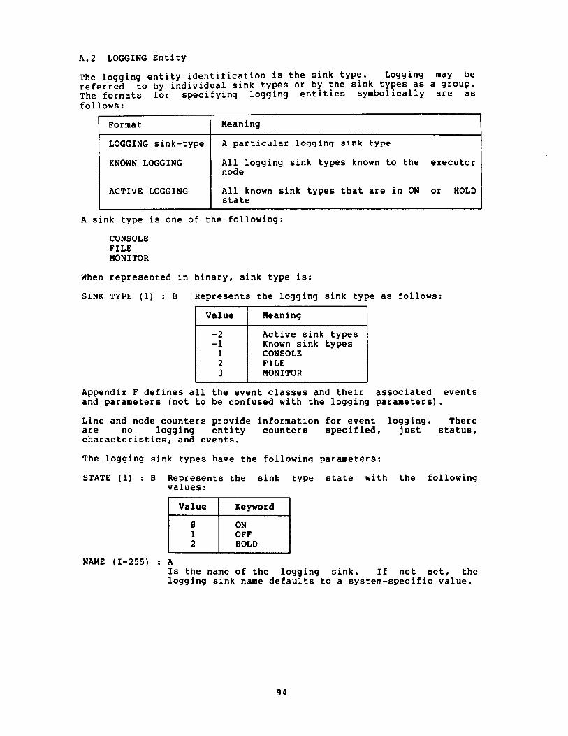
A.2 LOGGING Entity
KNOWN LOGGING All logging sink types known to the executor 1 node
The logging entity identification is the sink type. Logging may be referred to by individual sink types or by the sink types as a group. The formats for specifying logging entities symbolically are as follows:
Format
LOGGING sink-type
A sink type is one of the following:
Meaning
A particular logging sink type
1 ACTIVE LOGGING
CONSOLE FILE MONITOR
All known sink types that are in ON or state I
When represented in binary, sink type is:
SINK TYPE (1) : B Represents the logging sink type as follows:
Appendix F defines all the event classes and their associated events and parameters (not to be confused with the logging parameters).
Value
- 2 - 1 1 2 3
Line and node counters provide information for event logging. There are no logging entity counters specified, just status, characteristics, and events.
Meaning
Active sink types Known sink types CONSOLE FILE MONITOR
The logging sink types have the following parameters:
STATE (1) : B Represents the sink type state with the following values:
Value Keyword
HOLD
NAME (1-255) : A Is the name of the logging sink. If not set, the logging sink name defaults to a system-specific value.

SINK NODE Is the sink node identification that applies to all following event parameters until another sink node id is encountered. If not present, it defaults to executor node. The format for setting this parameter is described in Section A.3. Plural options are not allowed. When reading parameter, sink node consists of:
where :
NODE ADDRESS (2) : B Node address
NODE NAME (1-6) : A Node name, 0 length for none
EVENTS Are the sink type events, consisting of:
ENTITY ENTITY EVENT EVENT 1 TYPE 1 ID ICLASS 1 MASK 1 where :
ENTITY TYPE (1) : B Represents the entity type as follows :
No entity
LINE
ENTITY ID Is the entity id according to ENTITY TYPE, present only for NODE or LINE.
If ENTITY TYPE is NODE, format is as described for sink node.
If entity type is LINE, format is:
LINE ID (1-16) : A = Line id.
EVENT CLASS (2) : BM Entity class specification:
Bits
14-15
Meaning
0 = Single class 2 = All events for
class 3 = KNOWN EVENTS
Event class if bits 14-15 equal 0 or 2.

EVENT MASK (1-8) : B Event mask, bits set to correspond to event types (Table 12, Section F.2). Low order bytes first. High order bytes not present imply 0 value. Format for NCP input or output is a list of numbers corresponding to the bits set (Section 3.3.1.4). Only present if EVENT CLASS is for a single class (bits 14-15 = 0).
NOTE
The wild card and KNOWN EVENTS specifications are for changing events only. Return read events as a class and mask.
Table 8 summarizes the logging parameters.
Table 8 Logging Parameters
NOTE
Symbols are explained at the beginning of this appendix.
NICE Data Type
c-1
AI-255
CM-1/2 DU-2 AI-6
CM-2/3/4/5 c- 1 DU- 2
AI-6
AI-16
c- 2 HI-8
A.3 NODE Entity
Info Type
s
c*
EV*
EV*
NCP Keywords
STATE
NAME
SINK NODE Node address Node name (optional if none)
EVENTS Entity type Node address (if entity type is node) Node name (if entity type is node) Line id (if entity type is 1 ine) Event class Event mask (if single event class indicated)
The node entity is referred to by its keyword, NODE, followed by the node identification. The node identification is either the node address or node name except where limited in the command descriptions

(Section 3.3). Nodes, as a group, can be referred to as KNOWN or ACTIVE (see the glossary for definitions). The possible node entities are as follows:
NODE node-id EXECUTOR ACTIVE NODES KNOWN NODES LOOP NODES
When the executor or loop nodes are mixed in a multiple return with remote nodes, return the executor first, and the loop nodes last.
A node address is a unique decimal in the range 1 to MAXIMUM ADDRESS. Node address is the primary identification of a node, due to its use in the DIGITAL Network Architecture. Transport routes messages to node addresses only. Node names are optionally added in the Session Control layer as a convenience for users. A node address can have only one node name associated with it. However, implementations can use system-specific methods to provide users with "alias" node names (Transport Functional Specification).
A node name consists of one to six upper case alphanumeric characters with at least one alpha character. A node name must be unique within a node and should be unique within the network.
The format for displaying node identification is:
NODE = node-address [(node-name)]
For example:
NODE = 19 (ELROND)
The parentheses are only used if the node has a name. When represented in binary, node identification is one of four choices (limited by applicability to a particular function). All choices begin with a format type. The input format is as follows:
NODE FORMAT (1) : B Represents the node format type, as follows:
Loop nodes, no further data Active nodes, no further data Known nodes, no further data Node address Length of node name, followed by the indicated number of ASCII characters.
Number
In the ENTITY ID field of a response message bit 7 set indicates the node identification is the executor node.
Type
NODE ADDRESS (2) : B Is the node address if NODE FORMAT = 0. When used as input, a node address of zero implies the executor node.
NODE NAME : A Is the node name if NODE FORMAT >O.

The usual binary output format is as follows:
-1 where:
NODE ADDRESS (2) : B Is the node address. When supplied as output a node address of 0 indicates a loop node.
NODE NAME (1-6) : A Is the node name, 0 length implies none.
A.3.1 Node Parameters - The node entity has the following parameters: NODE STATE (1) : B
Except for the executor node state, this is a read only parameter.
Represents the executor or destination node state with the following values:
NODE IDENTIFICATION (1-32) : A Is the node identification string (for example, operating system and version number) .
NODE MANAGEMENT VERSION Is the node Network Management version, consisting of the following:
Node
Executor Executor Executor Executor Destination Destination
Value
0 1 2 3 4 5
VERSION (1) : B version number
Keyword
ON OFF SHUT RESTRICTED REACHABLE UNREACHABLE
ECO (1) : B Engineering Change Order (ECO) number
USER ECO (1) : B User ECO number
NODE SERVICE LINE (1-16) : A Is the line used to perform down-line load and up-line dump functions.
NODE SERVICE PASSWORD (1-8) : B Is the node service password for down-line loading and up-line dumping the node. The length in binary form corresponds to the length of the text form.
NODE SERVICE DEVICE (1) : B Is the device type over which the node handles service functions when in service slave mode. Code as defined in the MOP Functional Specification and correspond to the standard Network Management device mnemonics.
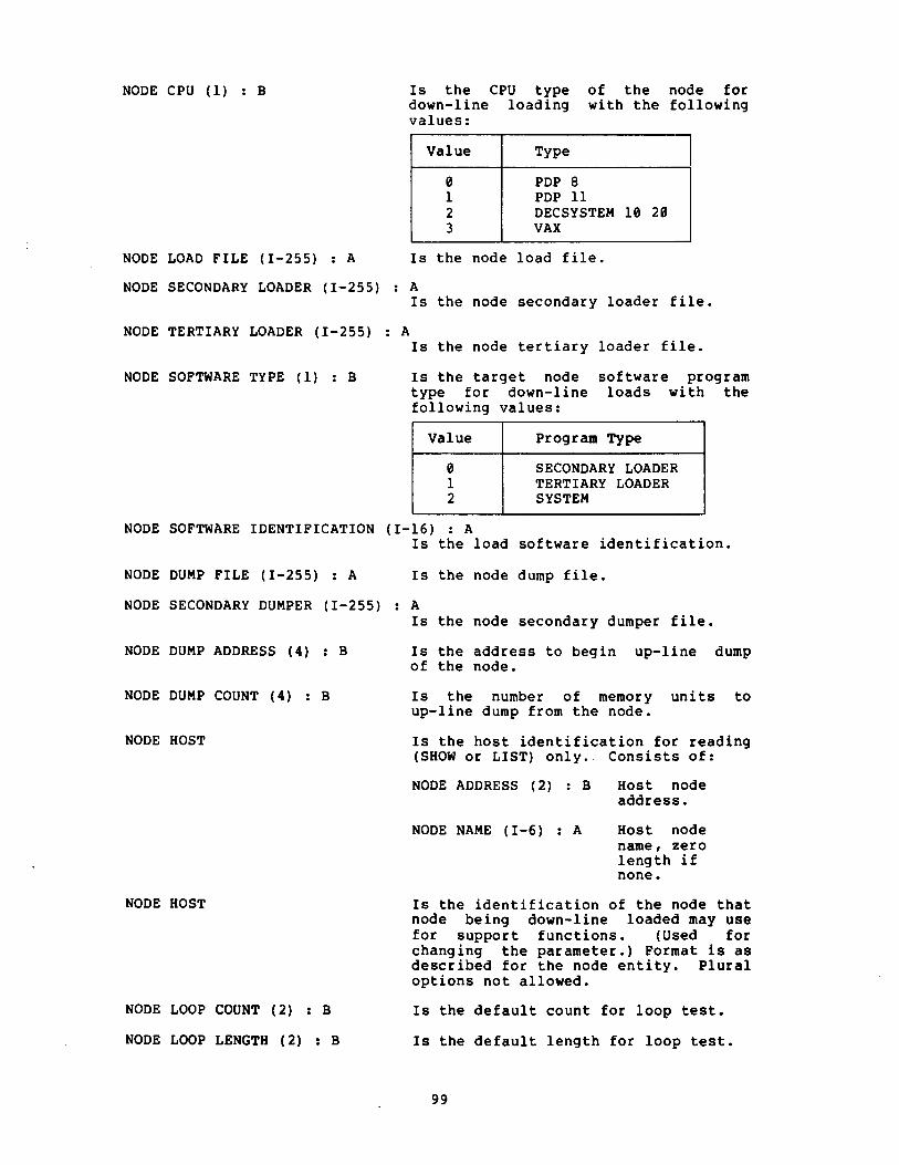
NODE CPU (1) : B
NODE SECONDARY LOADER (1-255) : A Is the node secondary loader file.
Is the CPU type of the node for down-line loading with the following values:
NODE TERTIARY LOADER (1-255) : A Is the node tertiary loader file.
Value
0 1 2 3
NODE SOFTWARE TYPE (1) : B Is the target node software program type for down-line loads with the following values:
Value Program Type
SECONDARY LOADER TERTIARY LOADER SYSTEM
NODE SOFTWARE IDENTIFICATION (1-16) : A Is the load software identification.
Type
PDP 8 PDP 11 DECSYSTEM 10 20 VAX
NODE DUMP FILE (1-255) : A Is the node dump file.
NODE LOAD FILE (1-255) : A Is the node load file.
NODE SECONDARY DUMPER (1-255) : A Is the node secondary dumper file.
NODE DUMP ADDRESS (4) : B Is the address to begin up-line dump of the node.
NODE DUMP COUNT (4) : B Is the number of memory units to up-line dump from the node.
NODE HOST
NODE HOST
NODE LOOP COUNT (2) : B
NODE LOOP LENGTH (2) : B
Is the host identification for reading (SHOW or LIST) only. Consists of:
NODE ADDRESS (2) : B Host node address.
NODE NAME (1-6) : A Host node name, zero length if none.
Is the identification of the node that node being down-line loaded may use for support functions. (Used for changing the parameter.) Format is as described for the node entity. Plural options not allowed.
Is the default count for loop test.
Is the default length for loop test.

NODE LOOP WITH (1) : B
NODE COUNTER TIMER (2) : B
NODE NAME ( 1-6) : A
NODE LINE (1-16) : A
NODE ADDRESS (2) : B
NODE INCOMING TIMER (2) : B
NODE OUTGOING TIMER (2) : B
NODE ACTIVE LINKS (2) : B
NODE DELAY (2) : B
NODE NSP VERSION
NODE MAXIMUM LINKS
NODE DELAY FACTOR
NODE DELAY WEIGHT
NODE INACTIVITY TIMER (2) :
Is the default block type for loop test with the following values:
Contents
ZEROES ONES MIXED
Is the number of seconds between node counter log events.
Is the node name.
Is the line used to get to the executor node and associated with a loopback node-name.
Is the executor node address.
Is the node incoming timer.
Is the node outgoing timer.
Is the number of logical links from the executor to the destination node.
Is the average round trip delay in seconds to the destination node. Kept on a remote node basis.
Is the node NSP version. Format same as for Network Management version.
Is the node maximum links.
Is the node delay factor.
Is the node delay weight.
B Is the node inactivity timer.
NODE RETRANSMIT FACTOR (2) : B Is the node retransmit factor.
NODE TYPE (1) : B Represents the executor node type with the following values:
NODE COST (2) : B
NODE HOPS (1) : B
NODE LINE (1-16) : A
1 Value 1 Keyword 1 ROUTING NONROUTING PHASE I1
Is the total cost over the current path to the destination node. Kept on a remote node basis.
Is the total number of hops over the current path to a destination node. Kept on a remote node basis.
Is the line used to get to a node other than the executor.
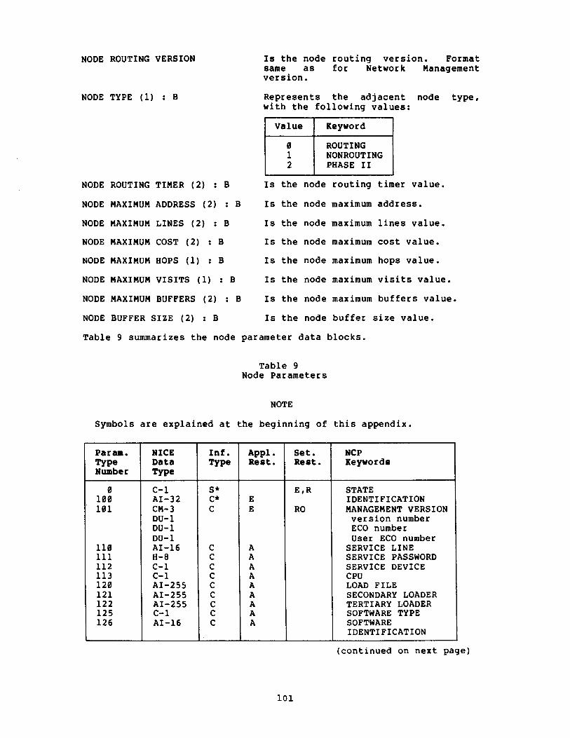
NODE ROUTING VERSION
NODE TYPE (1) : B
Is the node routing version. Format same as for Network Management version.
Represents the adjacent node type, with the following values:
ROUTING NONROUTING PHASE I1
NODE ROUTING TIMER ( 2 ) : B Is the node routing timer value.
NODE MAXIMUM ADDRESS (2) : B Is the node maximum address.
NODE MAXIMUM LINES (2) : B Is the node maximum lines value.
NODE MAXIMUM COST (2) : B Is the node maximum cost value.
NODE MAXIMUM HOPS (1) : B Is the node maximum hops value.
NODE MAXIMUM VISITS (1) : B Is the node maximum visits value.
NODE MAXIMUM BUFFERS (2) : B Is the node maximum buffers value.
NODE BUFFER SIZE (2) : B Is the node buffer size value.
Table 9 summarizes the node parameter data blocks.
Table 9 Node Parameters
NOTE
Symbols are explained at the beginning of this appendix.
Param. Type Number
NICE Data Type
c-1 AI-32 CM- 3 DU- 1 DU-1 DU-1 AI-16 H-8 c-1 c- 1 AI-255 AI-255 AI-255 c-1 AI-16
Inf . Type
NCP Keywords
Appl. Rest.
E E
A A A A A A A A A
- - - - - --
STATE IDENTIFICATION MANAGEMENT VERSION version number ECO number User ECO number
SERVICE LINE SERVICE PASSWORD SERVICE DEVICE CPU LOAD FILE SECONDARY LOADER TERTIARY LOADER SOFTWARE TYPE SOFTWARE IDENTIFICATION
Set. Rest.
EtR
RO
(continued on next page)
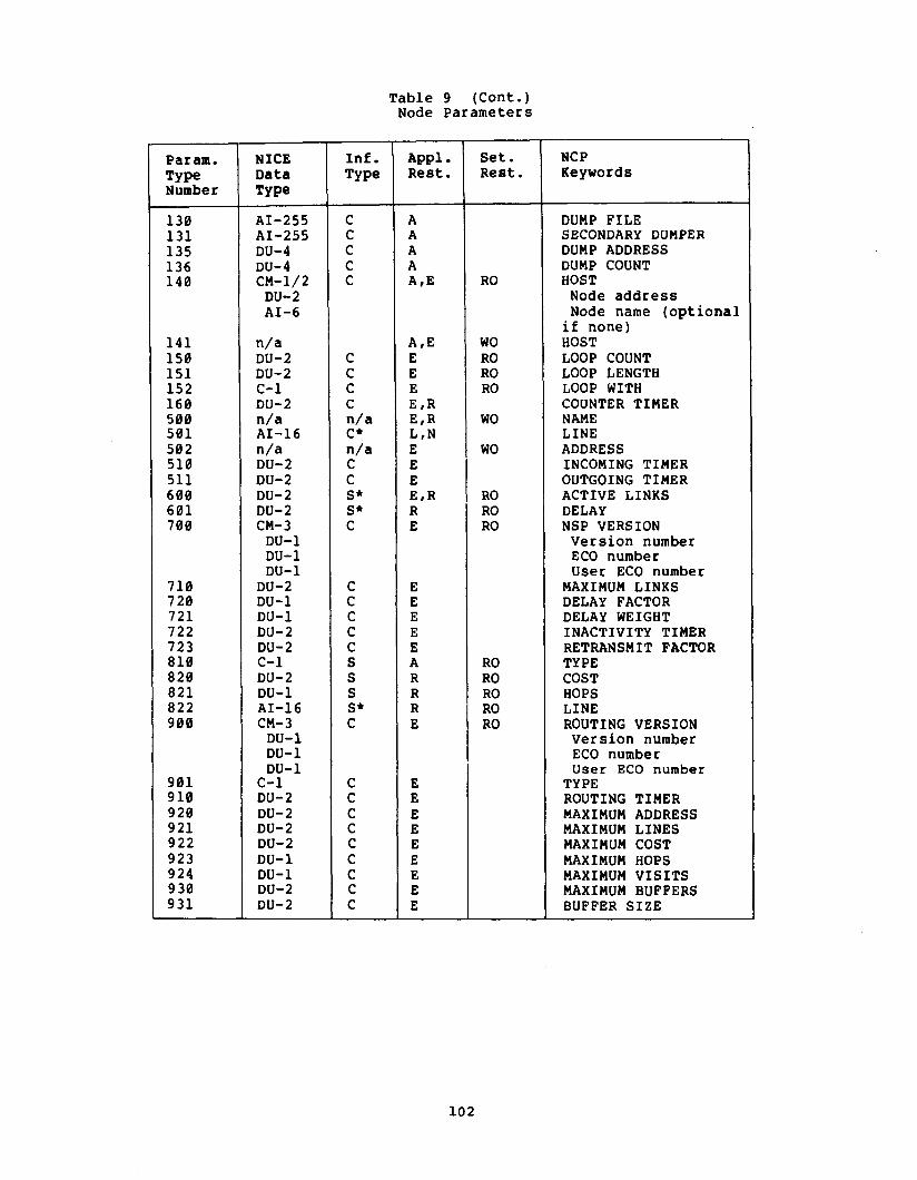
Table 9 (Cant.) Node Parameters
Param. TY Pe Number
130 13 1 13 5 136 140
141 150 15 1 152 160 500 501 502 510 5 11 600 601 700
710 720 721 722 723 810 820 821 822 900
9 0 1 910 9 20 921 922 923 9 24 930 931
NICE Data Type -
AI-255 AI-255 DU-4 DU-4 CM-1/2 DU-2 AI-6
n/a DU-2 DU-2 c-1 DU-2 n/a AI-16 n/a DU-2 DU-2 DU- 2 DU-2 CM- 3 DU-1 DU-1 DU-1
DU-2 DU-1 DU-1 DU- 2 DU- 2 c-1 DU- 2 DU-1 AI-16 CM- 3 DU-1 DU-1 DU-1
c-1 DU- 2 DU-2 DU-2 DU-2 DU-1 DU-1 DU-2 DU-2
Inf. Type
A P P ~ Rest.
Set. Rest.
NCP Keywords
- -
DUMP FILE SECONDARY DUMPER DUMP ADDRESS DUMP COUNT HOST Node address Node name (optional if none) HOST LOOP COUNT LOOP LENGTH LOOP WITH COUNTER TIMER NAME LINE ADDRESS INCOMING TIMER OUTGOING TIMER ACTIVE LINKS DELAY NSP VERSION Version number ECO number User ECO number
MAXIMUM LINKS DELAY FACTOR DELAY WEIGHT INACTIVITY TIMER RETRANSMIT FACTOR TYPE COST HOPS LINE ROUTING VERSION Version number ECO number User ECO number
TYPE ROUTING TIMER MAXIMUM ADDRESS MAXIMUM LINES MAXIMUM COST MAXIMUM HOPS MAXIMUM VISITS MAXIMUM BUFFERS BUFFER SIZE

A.3.2 Node Counters - Table 10, below, lists the node counters. The definition of each counter and the way it is to be incremented is given in the functional specifications for the layer containing the counter.
Node counters are specified for the following layers only:
Layer Type Number
Network Management
I Network Services I 600'S, 700 I
Type Number
Transport
Table 10 Node Counters
900 s
Bit width Standard Text
Seconds Since Last Zeroed
Bytes Received Bytes Sent Messages Received Messages Sent Connects Received Connects Sent Response Timeouts Received Connect Resource Errors Maximum Logical Links Active
Aged Packet Loss Node Unreachable Packet Loss Node Out-of-Range Packet Loss Oversized Packet Loss Packet Format Error Partial Routing Update Loss Verification Reject
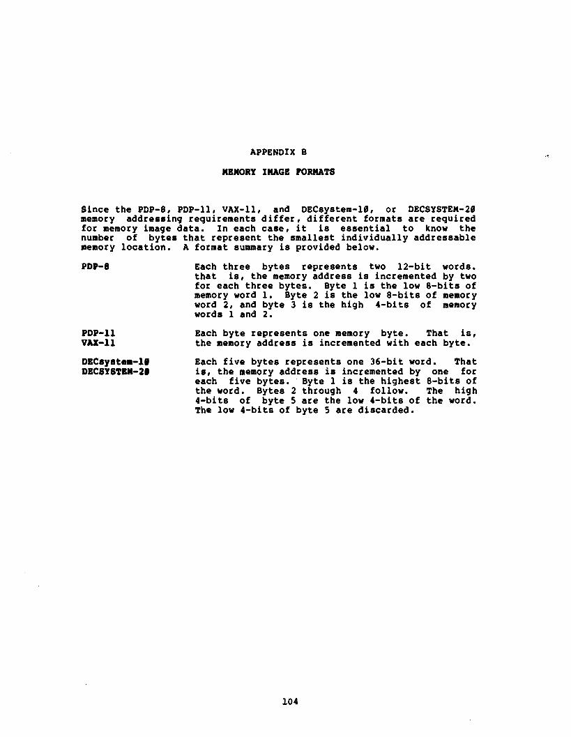
APPENDIX B
MEMORY IMAGE FORMATS
Since the PDP-8, PDP-11, VAX-11, and DECsystem-10, or DECSYSTEM-20 memory addressing requirements differ, different formats are required for memory image data. In each case, it is essential to know the number of bytes that represent the smallest individually addressable memory location. A format summary is provided below.
PDP-11 VAX- 11
Each three bytes represents two 12-bit words. that is, the memory address is incremented by two for each three bytes. Byte 1 is the low 8-bits of memory word 1. Byte 2 is the low 8-bits of memory word 2, and byte 3 is the high 4-bits of memory words 1 and 2.
Each byte represents one memory byte. That is, the memory address is incremented with each byte.
DECsystem-10 Each five bytes represents one 36-bit word. That DBCSYSTBN-21 is, the memory address is incremented by one for
each five bytes. Byte 1 is the highest 8-bits of the word. Bytes 2 through 4 follow. The high 4-bits of byte 5 are the low 4-bits of the word. The low 4-bits of byte 5 are discarded.

APPENDIX C
MEMORY IMAGE PILE CONTENTS
The files containing memory images for a down-line load or an up-line dump have the same contents. The format may vary from one operating system to another, but the contents are functionally the same in all cases. The minimum control information required is as follows:
0 The type of the target system (PDP-8, PDP-11, VAX-11, DECsystem-10, or DECSYSTEM-20). This is necessary to know how to interpret and update memory address information.
0 Transfer address. This is the startup address for the program. This field is generally meaningless for a dump file.
The image information required is as follows:
0 Memory address. This is the address where image goes for a load or comes from a dump.
0 Block length. Number of memory units in image block.
0 Memory image. This is the contiguous block of memory associated with the above address. The format requirements are as specified in Appendix B. The memory image can be of any length.

APPENDIX D
NICE RETURN CODES WITH EXPLANATIONS
Th i s appendix s p e c i f i e s t h e N I C E r e t u r n codes.
In a l l c a s e s , t h e number s p e c i f i e d is f o r t h e f i r s t by te of t h e r e t u r n code.
The e r r o r d e t a i l t h a t sometimes fo l lows t h e r e t u r n codes is two b y t e s long. S ince some systems may have t r o u b l e implementing t h e e r r o r d e t a i l s , a va lue of 65,535 ( a l l 16 b i t s s e t ) i n t h e e r r o r d e t a i l f i e l d means no e r r o r d e t a i l . In o the r words, i n t h i s c a s e , no e r r o r d e t a i l w i l l be p r i n t e d .
I f a response message is s h o r t terminated a f t e r any f i e l d , t h e e x i s t i n g f i e l d s may s t i l l be i n t e r p r e t e d according t o t h e s t anda rd format .
A p r i n t e d e r r o r message c o n s i s t s of t h e s t anda rd t e x t f o r t h e f i r s t by te . I f t h e second and t h i r d by t e s have a def ined v a l u e , t h i s is followed by a comma, a b lank , and t h e keyword(s) fo r t h e va lues .
Number Standard t e s t
( none
( none
(none
Unrecognized func t ion or op t ion
I n v a l i d message format
Meaning
Success .
The r eques t has been accep ted , and more responses a r e coming.
Success , p a r t i a l r ep ly . More parameters fo r e n t i t y i n next message. Can on ly be embedded i n a more/done sequence. Each message s t i l l c o n t a i n s f i e l d s up through ENTITY I D .
E i t he r t h e func t ion code or op t ion f i e l d reques ted a c a p a b i l i t y no t recognized by t h e Local Network Management Function. Also, t h e e r r o r code f o r func t ion codes 2-14 (Phase 11) , and f o r sys tem-spec i f ic commands when t h e system type matches t h e r ece iv ing system.
Message too long o r t oo s h o r t i . e . , e x t r a d a t a o r no t enough d a t a ) , o r a f i e l d improperly formatted fo r d a t a expected.
(cont inued on next page)

Number Standard test
Privilege violation
Over sized Management command message
Management program error
Unrecognized parameter type
Incompatible Management version
Unrecognized component
Invalid identification
Line communication error
Component in wrong state
Meaning
The requestor does not have the privilege required to perform the requested function.
A message size was too long. The NICE message for the command was too long for the Network Management Listener to receive.
A software error occurred in the Network Management software. For example, a function that could not fail did fail. Generally indicates a Network Management software bug.
A parameter type included in, for example, a change parameter message not recognized by the Network Management Function.
The error detail is the low and high bytes of the parameter type number, interpreted according to the entity involved.
The function requested cannot be performed because the Network Management version skew between the command source and the command destination is too great.
An entity (component) was not known to the node. The error detail contains the entity type number. * The format of an entity identification was invalid. For example, a node name with no alpha character, or KNOWN used where not allowed. The error detail contains the entity type number. *
Error in transmit or receive on a line. Can only occur during direct use of the Data Link user interface.
An entity (component) was in an unacceptable state. For example, a down line load attempted over a line that is OFF, or a node name to be used for a loop node already assigned to a node address. The error detail contains the entity type number. *
(continued on next page)

Dumber
-13
-14
-1 5
-16
-17
-18
Standard test
File open error
Invalid file contents
Resource error
Invalid parameter value
Line protocol error
Pile 1/0 error
Meaning
A file could not be opened.
The error detail is defined as follows :
1 Value 1 Keywords PERMANENT DATABASE LOAD FILE DUMP FILE SECONDARY LOADER TERTIARY LOADER
5 SECONDARY DUMPER
The data in a file was invalid. The error detail is defined as for error #-13.
Some resource was not available. For example, an operating system resource not available.
Improper line-identification type, load address, memory length, etc. The error detail is the low and high bytes of the parameter type number, interpreted according to the entity involved.
Invalid line protocol message or operation. Can only occur during direct line access. In the case of a line loop test, it indicates that an error was detected during message comparison that should have been caught by the line protocol.
1/0 error in a file, such as read error in system image or loader during down-line load.
The error detail is defined as for error (-13.
(continued on next page)

Number Standard test - --
Mirror link disconnected
No room for new entry
Mirror connect failed
Parameter not applicable
Meaning
A successful connect was made to the Loopback Mirror, but the logical link then failed.
The error detail is:
Value
Insuffic entry.
ent table space for new
Standard text
No node name set Invalid node name format Unrecognized node name Node unreachable Network resources Rejected by object Invalid object name format Unrecognized object Access control rejected Object too busy No response from object Remote node shut down Node or object failed Disconnect by object Abort by object Abort by Management Local node shut down
A connect to the Network Management Loopback Mirror could not be completed. The error detail is the same as for error #-19.
l
Parameter not applicable to entity. For example, setting a tributary address for a point-to-point line or an attempt to set a controller to loopbac k mode when the controller does not support that function. The error detail contains the parameter type of the parameter that is not applicable.
(continued on next page)
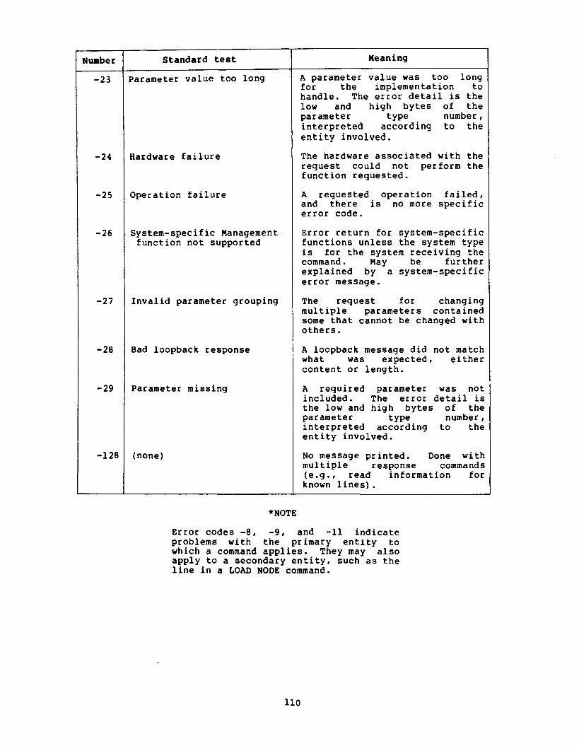
Number
-23
-24
-25
-26
-27
-28
-29
-128
Standard test - -
Parameter value too long
Hardware failure
Operation failure
System-specific Management function not supported
Invalid parameter grouping
Bad loopback response
Parameter missing
(none)
Meaning
A parameter value was too long for the implementation to handle. The error detail is the low and high bytes of the parameter type number , interpreted according to the entity involved.
The hardware associated with the request could not perform the function requested.
A requested operation failed, and there is no more specific error code.
Error return for system-specific functions unless the system type is for the system receiving the command. May be further explained by a system-specific error message.
The request for changing multiple parameters contained some that cannot be changed with others.
A loopback message did not match what was expected, either content or length.
A required parameter was not included. The error detail is the low and high bytes of the parameter type number, interpreted according to the entity involved.
No message printed. Done with multiple response commands (e.g., read information for known lines) .
Error codes -8, -9, and -11 indicate problems with the primary entity to which a command applies. They may also apply to a secondary entity, such as the line in a LOAD NODE command.

APPENDIX E
NCP COMMAND STATUS AND ERROR MESSAGES
NCP has the following standard status and error messages. -- ~ -
Standard Text
COMPLETE
FAILED
NOT ACCEPTED
Unrecognized command
Unrecognized keyword
Value out of range
Unrecognized value
Not remotely executable
Bad management response
Listener link disconnected
Meaning
Status Messages
The command was processed successfully.
The command did not execute successfully.
The command did not get past syntax and semantic checking. No attempt was made to execute it. The text of the error message may vary as long as the meaning is clearly the same.
Error Messages
The command typed by the user was not recognized.
Something in the command keyword was not recognized.
A parameter value was out of range. This message may be followed by a comma, a blank and the parameter keyword(s) . A parameter value was unrecognizable. This message may be followed by a comma, a blank and the parameter keyword(s).
NCP is functionally unable to send a command to a remote node.
The Network Management Access Routines received unrecognizable information.
A successful connect was made to the Network Management Listener, but the logical link then failed. Optional error detail is as in NICE error message -19 (Appendix D).
(continued on next page)
Ill

1 Standard Text 1 Meaning
Listener connect failed
Total parameter data too long
Oversized Management response
Error Messages
A connect to the Network Management Listener could not be completed. The optional error detail is as in NICE error message -21 (Appendix D) .
I ' NCP command overflows maximum NICE message for this implementation. ~ NCP could not receive a NICE message because it was too long.

APPENDIX F
EVENTS
F.1 Event Class Definitions
Table 11, following, defines the event classes. The event class as shown in Table 11 is a composite of the system type and the system specific event class.
Table 11 Event Classes
Event Class Description
--
Network Management Layer Applications Layer Session Control Layer Network Services Layer Transport Layer Data Link Layer Physical Link Layer Reserved for other common classes
RSTS System specific
RSX System specific
TOPS-20 System specific
VMS System specific
Reserved for future use
Customer specific
F.2 Event Definitions
In the following descriptions, an entity related to an event indicates that the event can be filtered specific to that entity. Binary logging data is formatted under the same rules as the data in NICE data blocks (see Appendix A) . Section F. 3 describes the event parameters associated with each event type.
Table 12 shows the events for each class.

Table 12 Events
Class
0 0 0 0
0 0 0 0
2
2
3 3
3
4 4 4 4 4 4
4 4 4
4
4 4
4
4
4
5
Entity
none node 1 ine 1 ine
line node 1 ine line
none
none
none none
node
none 1 ine 1 ine line 1 ine line
1 ine line line
line
line line
line
line
node
line
Standard Text
Event records lost Automatic node counters Automatic line counters Automatic line service
Line counters zeroed Node counters zeroed Passive loopback Aborted service request
Local node state change
Access control reject
Invalid message Invalid flow control
Data base reused
Aged packet loss Node unreachable packet loss Node out-of-range packet loss Oversized packet loss Packet format error Partial routing update loss
Verification reject Line down, line fault Line down, software fault
Line down, operator fault
Line up Initialization failure, line fault Initialization failure, so tware fault Initialization failure, operator fault
Node reachability change
Locally initiated state change
Event Parameters and Counters
none Node counters Line counters Service Status Line counters Node counters Operation Reason
Reason Old state New state Source node Source process Destination process User Password Account
Message Message Current flow control NSP node counters
Packet header Packet header Packet header Packet header Packet beginning Packet header Highest address Node Reason Reason Packet header Reason Packet header Expected node Node Reason
Reason Packet header Reason Packet header Received version Status
Old state New state
[continued on next page)

Table 12 (Cont.) Events
Class Type Entity
1 ine
1 ine
1 ine
line
line
line line
line
1 ine
line line line 1 ine 1 ine 1 ine
Standard Text
Remotely initiated state change
Protocol restart received in maintenance mode Send error threshold
Receive error threshold
Select error threshold
Block header format error Selection address error
Streaming tributary
Local buffer too small
Data set ready transition Ring indicator transition Unexpected carrier transition Memory access error Communications interface error Performance error
Event Parameters and Counters
Old state New state none
Line counters, including station
Line counters, including station
Line counters, including station
Header (optional) Selected tributary Received tributary Previous tributary Tributary status Received tributary Block length Buffer length
New state New state New state Device register Device register Device register
Counters are defined in Appendix A.
F.3 Event Parameter Definitions
The following parameter types are defined for the Network Management layer (class 0) :
Type 1 Data Type 1 Keywords
SERVICE
STATUS Return code Error detail (optional if no error message) Error message (optional)
OPERATION REASON

where :
SERVICE (1) : B Represents the service type as follows:
STATUS
Value Keyword
DUMP
Is the operation status, consisting of:
where:
RETURN CODE
RETURN CODE (1) : B = Standard NICE return code, with added interpretation:
Value Keyword
REQUESTED SUCCESSFUL
< 0 FAILED
ERROR DETAIL (2) : B = Standard NICE error detail.
ERROR DETAIL
ERROR MESSAGE(1-72) : A = Standard NICE optional
error message.
ERROR MESSAGE
OPERATION (1) : B Represents the operation performed, as follows:
REASON (1) : B
Keyword
INITIATED TERMINATED
Represents the reason aborted, as follows:
Value Reason I
Receive timeout Receive error Line state change by higher level Unrecognized request Line open error

The following parameter types are defined for the Session Control layer (class 2) :
Data Type
DU- 1
where:
REASON (1) : B
Keywords
REASON
OLD STATE
NEW STATE
SOURCE NODE node address node name (optional if none)
SOURCE PROCESS Object type Group code, (if specified and process name present) User code, (if specified and group code present) Process name, if specified
DESTINATION PROCESS Same as for SOURCE PROCESS
USER
PASSWORD
ACCOUNT
Represents the reason for state change, as follows:
Operator command Normal operation 1
Value
OLD STATE (1) : B
Meaning
Represents the old node state, as follows:
NEW STATE (1) : B
1 Value 1 Meaning 1
Represents the new node state, coded same as OLD STATE.
0 1 2 3
ON OFF SHUT RESTRICTED

SOURCE NODE Is the source node identification, consisting of:
1 NODE 1 NODE 1 ADDRESS NAME
where:
NODE ADDRESS (2) : B = Node address (see Section A . 3 ) .
NODE NAME (1-6) : A = Node name, 0 length if none.
SOURCE PROCESS Is the source process identification, consisting of:
where:
OBJECT TYPE
OBJECT TYPE (1): B = Object type number
GROUP CODE (I): b = Group code number
GROUP CODE
USER CODE (1) : B = User code number
PROCESS NAME(1-16):A = Process name
USER CODE
DESTINATION PROCESS Is the destination process identification, defined as for SOURCE PROCESS.
PROCESS NAME
USER (1-39) : A Is the user identification
PASSWORD (1) : B Is the password indicator. A value of zero indicates a password was set. Absence of the parameter indicates no password was set.
ACCOUNT (1-39) : A Is the account information
The following parameter types are defined for the Network Services layer (class 3) :
Type
0
1
Data Type
CM-4 H- 1 DU- 2 DU-2 HI-6
DU-1
Keywords
MESSAGE Message flags Destination node address Source node address Message type dependent data
CURRENT FLOW CONTROL

where:
MESSAGE (1-12) : B
where :
Is the message received (NSP information only). Consists of:
MESSAGE FLAGS (1) :B = Message flags
MESSAGE FLAGS
DESTINATION NODE(2):B = Destination node address
SOURCE NODE
DATA(1-6) :B
(2) :B = Source node address
DATA DESTINATION NODE
= Message type dependent data
SOURCE NODE
CURRENT FLOW CONTROL (1) : B Is the current flow control value
The following parameter types are defined for the Transport layer (class 4) :
Data Type
CM-4 H-1 DU-2 DU-2 H-1
HI-6
DU- 2
CM-1/2 DU-2 AI-6
CM-1/2 DU-2 AI-6
c-1
CM-3 DU-1 DU-1 DU-1
C-1
Keywords
PACKET HEADER Message flags Destination node address Source node address Forwarding data
PACKET BEGINNING
HIGHEST ADDRESS
NODE node address node name (optional if none)
EXPECTED NODE node address node name (optional if none)
REASON
RECEIVED VERSION Version number ECO number User ECO number
STATUS

where:
PACKET HEADER Is the packet header consisting of:
where:
MESSAGE FLAGS
,
MESSAGE FLAGS (1) : B = Message definition flags
DESTINATION NODE
ADDRESS
DESTINATION NODE ADDRESS(2):B = Address of destination node
SOURCE NODE ADDRESS (2): B = Address of source node
SOURCE NODE
ADDRESS
FORWARDING DATA ( 1 ) : B = Message forwarding data
FORWARDING DATA
PACKET BEGINNING (6) : B Is the beginning of packet.
HIGHEST ADDRESS (2) : 0 Is the highest unreachable node address.
NODE
EXPECTED NODE
Is the node identification in the same format as SOURCE NODE in Session Control events.
Is the expected node identification in the same format as SOURCE NODE in Session Control events.
REASON (1) : B Is the failure reason:
Value
0 1 2 3 4 5 6 7
8
9 10
11
1
Meaning
Line synchronization lost Data errors Unexpected packet type outing update checksum error Adjacent node address change Verification receive timeout Version skew Adjacent node address out of range Adjacent node block size too small Invalid verification seed value Adjacent node listener receive timeout Adjacent node listener received invalid data

RECEIVED VERSION Is the received version number, consisting of:
STATUS (1) : B
where :
VERSION
VERSION (1) : B = Version number.
ECO (1) : B = ECO number.
USER ECO ( I ) : B = User ECO number.
ECO
Represents the node status, as follows:
USER ECO
REACHABLE 1 1 UNREACHABLE
The following parameter types are defined for the Data Link layer (class 5):
where:
Data Type
OLD STATE (1): B
NEW STATE
HEADER (1-6) : B
SELECTED TRIBUTARY ( I)': B
RECEIVED TRIBUTARY(1): B
Keywords
OLD STATE
NEW STATE
HEADER
SELECTED TRIBUTARY
PREVIOUS TRIBUTARY
TRIBUTARY STATUS
RECEIVED TRIBUTARY
BLOCK LENGTH
BUFFER LENGTH
Represents the old DDCMP state, as follows:
Value 1 Meaning I
Represents the new DDCMP state, as defined for OLD STATE.
0 1 2 3 4
Is the block header
HALTED ISTRT ASTRT RUNNING MAINTENANCE
Is the selected tributary address
Is the received tributary address

PREVIOUS TRIBUTARY(1): B Is the previously selected tributary address
TRIBUTARY STATUS (I): B Is the tributary status, as follows:
1 Value 1 Meaning 1
BLOCK LENGTH (2) : B Is the received block length from header, in bytes
BUFFER LENGTH (2) : B Is the buffer length, in bytes
The following parameter types are defined for the Physical Link layer
0 1 2 3
- -
(class 6) :
Data Type Keywords
DEVICE REGISTER
NEW STATE
where:
Streaming Continued send after timeout Continued send after deselect Ended streaming
DEVICE REGISTER(2) : B Represents a single device register. When more than one, they should be output in standard order.
NEW STATE ( 1) : B Represents the new modem control state, as follows :
Value Meaning m

APPENDIX G
JULIAN HALF-DAY ALGORITHMS
The following algorithms will convert to and from a Julian half-day in the range 1 January 1977 through 9 November 2021 as used in the binary format of event logging records.
The algorithms will operate correctly with 16 bit arithmetic. The arithmetic expressions are to be evaluated using FORTRAN operator precedence and integer arithmetic.
In all cases, the input is assumed to be correct, i.e., the day is in the range 1 to maximum for the month, the month is in the range 1-12, the year is in the range 1977-2021 and the Julian half-day is in the range 0-32767.
To convert to Julian half-day:
To convert from Julian half-day:
HALF = JUL IAN/2 TEMPI = HALF/1461 TEMP2 = HALF-TEMPI YEAR = TEMP2/365 I F TEMP2/1460*1460 = TEMP2 AND (HALF+1)/146O > TEMPI
YEAR = YEAR-1 ENDIF TEMPI = TEMP2-(YEARÇ365)t YEAR = YEARt1977 I F YEAR/4*4 = YEAR
TEMP2 = 1 ELSE
TEMP2 = 0 ENDIF I F TEMPI > 59tTEMP2
DAY DAYt2-TEMP2 ELSE
DAY - TEMPI ENDIF MONTH = <DAY+91)È100/305 DAY = DAY+91-MONTHÇ3055/10 MONTH a- MONTH-2 I F HALFÈ = JULIAN
HALF = 0 ELSE
HALF = 1 ENDIF

The algorithm was certified to work using the following FORTRAN program running in FORTRAN IV+ on RSX-11M:
INTEGER*4 COUNT INTEGERÇ JULTESÈJULIANÈDAYÈHONTHÈYEARÈJULTEM
! DO 1099 COUNT=0~32767
JULTES=COUNT CALL UNJUL(JULTESÈHALFÈDAYÈHONTHÈY JULTEM=JULIAN<DAYÈMONTHVYEAR)+HAL I F <JULTEM*EQ*JULTES) GOT0 1099
TYPE ~OÈJULTESÈJULTEMÈHALFÈDAYÈMONTH 10 FORMAT < X ~ ' E r r o r ! ' ~ 6 1 7 ) 1099 CONTINUE
END ! t INTEGER FUNCTION TO CONVERT DAY? MONTH AND YEAR TO JULIAN HALF-DAY !
INTEGER*2 FUNCTION JULIAN(DAYÈMONTHÈYEA INTEGERÇ DAYÈMONTHÈYE
! JULIAN = <3055È<MONTH+2)/100-<HONTHt10~/13Ç2-
t +<1-(YEAR-YEAR/4Ç4+3)/4)Ç<MONTH+10)/13+DAY t t<YEAR-1977)Ç365+<YEAR-1977)/4)Ã
RETURN END
! ! SUBROUTINE TO CONVERT JULIAN HALF-DAY TO DAY? MONTH AND YEAR !
SUBROUTINE UNJUL(JULIANÈHALFÈDAYÈMONTHÈY INTEGERÇ JULIANÈHALFÈDAYÈMONTH~YEARÈTEMP~È
t HALF = JULIAN/2 TEMP1 = HALF/1461 TEMP2 a HALF-TEMPI YEAR = TEMP2/365 I F ~ T E M P ~ / ~ ~ ~ ~ Ã ‡ ~ ~ ~ ~ ~ E Q ~ T E M P ~ Ã ‡ A N D ~ ( H A L F + ~ ) / ~ ~ ~ ~ * O T ~ T E M P
8 YEAR = YEAR-1 TEMP1 - TEMP2-(YEARÇ365)t YEAR-YEARt1977 TEMP2 = 0 I F (YEAR/4*4eEQ*YEAR) TEMP2 - 1 DAY - TEMPI I F (TEHP~ÈGT*S~+TEHP~ DAY - DAYt2-TEMP2 MONTH - <DAY+91>È100/30S DAY = DAYt91-MONTHÇ3055/10 MONTH = MONTH-2 TEMP1 - 0 I F <HALFÇ2*NEeJULIAN TEMPI = 1 HALF = TEMP1 RETURN END

APPENDIX H
DMC DEVICE COUNTERS
The following counters a r e the only ones appl icable t o the DMC device.
Standard Text I Bytes received Bytes sen t Data blocks received Data blocks sen t Data e r r o r s inbound 0 N A K s s en t , header block check e r ro r 1 N A K s s en t , da ta f i e l d block check e r ro r Data e r r o r s outbound Remote reply timeouts Local rep1 y timeouts Local buffer e r r o r s 0 N A K s s en t , buffer unavailable
None of the other standard counters can be kept due t o the nature of the DMC hardware. The "Data e r r o r s outbound" counter is kept w i t h no bitmap. I t represents the sum of a l l NAKs received.
Since the counters kept by the DMC firmware cannot be zeroed in t,he way t h a t driver-kept counters can, the recommended technique for providing the zero capab i l i ty is t o copy the base t ab l e counters when a zero is requested. The numbers returned when counters a r e requested a r e then the d i f fe rence between the saved counters and the cur ren t base t ab le .

APPENDIX I
NCP COMMANDS SUPPORTING EACH NETWORK MANAGEMENT INTERFACE
This appendix shows the NCP commands supporting the Network Management interface to each of the lower DNA layers.

( This notation precedes keywords or
text returned on SHOW or
LIST commands
A.
Network Management Layer Interface
EXECUTOR
{ki!iN
LINE
line-id
LOGGING
KNOWN LOGGING
NODE
node- id
NODE
ALL
COUNTER TIMER
SERVICE
STATE
ALL
EVENT event-list
KNOWN EVENTS
NAME
STATE
ALL
COUNTER TIMER
C PU
DUMP ADDRESS
DUMP COUNT
DUMP FILE
HOST
IDENTIFICATION
LOAD FILE
SECONDARY D
UMPER
SECONDARY LOADER
SERVICE DEVICE
SERVICE LINE
SERVICE PASSWORD
SOFTWARE
IDENTIFICATION
SOFTWARE T
YPE
TERTIARY LOADER
destination-node
seconds
service-control
line-state
source-qua1 sink-node
source-qua1 sink-node
sink-name
sink-state
seconds
cpu-type
number
number
f ile-id
node- id
string
f ile-id
f ile-id
f ile-id
device-type
1 ine- id
password
f ile-id
program-type
f ile-id


A.
Network Management Layer Interface (Cont.)
I-'
hl
w
DUMP
LOOP
node- id
line-id
DUMP ADDRESS
DUMP COUNT
SECONDARY DUMPER
SERVICE DEVICE
SERVICE PASSWORD
TO dump-file
*VIA line-id
number
number
f ile-id
device-type
password
COUNT
WITH
LENGTH
count
block-type
length
- -
1 ine-id
SINK node-id}
1 STATUS
~TATE
{KNOWN
SINKS
STATUS
CHARACTERISTICS
COUNTERS
(STATE-substate
(SERVICE
seconds since last-
zeroed
CHARACTERISTICS
EVENTS
NAME
See
Section A.2

A.
Network Management Layer Interface (Cont.)
SHOW
ZERO
ACTIVE NODES
EXECUTOR
LOOP NODES
KNOWN NODES
node-id
I COUNTERS
I
I
QUEUE
CHARACTERISTICS
^ DDRESS
COUNTER TIMER
CPU
DUMP ADDRESS
DUMP COUNT
DUMP FILE
HOST
IDENTIFICATION
LOAD FILE
MANAGEMENT VERSION
NAME
SECONDARY DUMPER
SECONDARY LOADER
SERVICE DEVICE
SERVICE LINE
SERVICE PASSWORD
SOFTWARE IDENTIFICATION
SOFTWARE TYPE
[TERTIARY LOADER
seconds since last
zeroed
{;EN LINES
1 ine-id
{l:::N
NODES
node-id}
COUNTERS
COUNTERS

ui 0 ID u 4J '0 2 10 ' O M ' 0 1 0 M U 10'0 c ' 0 m C I I C I 0 0 0 0 0 0 5 0 C 5 0 5 0 a.4 0 0 0 C M d C ( 0 C

C.
Network Services L
ayer Interface
I-" w
N>
EXECUTOR
EXECUTOR
ZERO
D.
Transport Layer Interface
ALL
DELAY FACTOR
number
DELAY WEIGHT
number
INACTIVITY T
IMER
seconds
MAXIMUM LINKS
number
RETRANSMIT FACTOR
number
CHARACTERISTICS
COUNTERS
STATUS
COUNTERS
{ii!iN
LINES
1 ine
-id
{:z&N NODES
node-id
DELAY FACTOR
DELAY WEIGHT
INACTIVITY T
IMER
MAXIMUM LINKS
NSP V
ERSION
RETRANSMIT FACTOR
See T
able 10
LINKS
ALL
COST
cost
ALL
BUFFER SIZE
memory-uni ts
MAXIMUM ADDRESS
number
MAXIMUM BUFFERS
number
MAXIMUM COST
number
MAXIMUM HOPS
number
MAXIMUM LINES
number
MAXIMUM VISITS
number
ROUTING TIMER
seconds
TYPE
node-type

D.
Transport Layer Interface (Cont.)
1 ine- id
KNOWN LINES
ACTIVE LINES
1 ine-id
KNOWN LINES
ACTIVE LINES
1 ine-id
KNOWN LINES
ACTIVE LINES
EXECUTOR
KNOWN NODES
ACTIVE NODES
LOOP NODES
node- id
EXECUTOR
KNOWN NODES
ACTIVE NODES
LOOP NODES
node- id
EXECUTOR
KNOWN NODES
ACTIVE NODES
LOOP NODES
node- id
1 ine- id
{;::EN LINES
CHARACTERISTICS
STATUS
COUNTERS
CHARACTERISTICS
STATUS
COUNTERS
COUNTERS
See Table 7
BUFFER SIZE
MAXIMUM ADDRESS
MAXIMUM BUFFERS
MAXIMUM COST
MAXIMUM HOPS
\ MAXIMUM LINES
MAXIMUM VISITS
ROUTING TIMER
ROUTING VERSION
COST
HOPS
LINE
STATE
TYPE
See Table 10
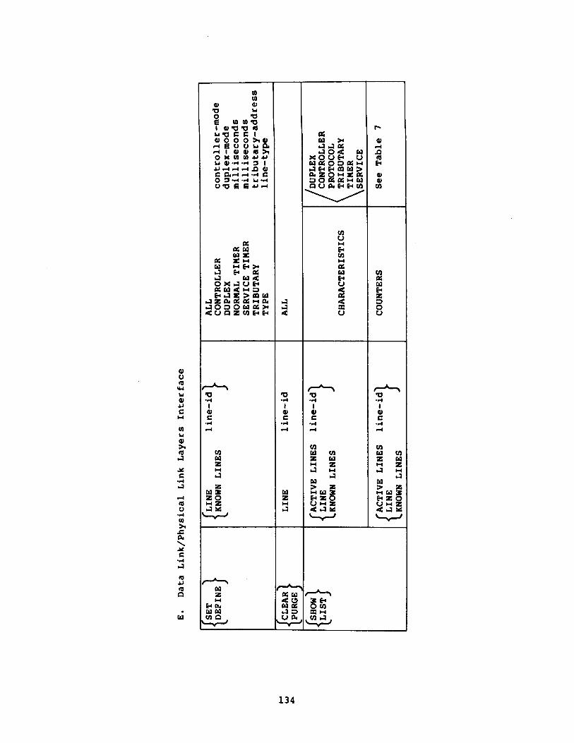
E.
Data Link/Physical Li
nk Layers Interface
p;:INE}
CLEAR
PURGE
{
{k&
LINES
1 ine-id
LINE
1 ine-id
ACTIVE LINES
line-id 1
{LINE
KNOW
N LINES
ACTIVE LINES
line
-id
KNOW
N LINES
ALL
CONTROLLER
controller-mode
DUPLEX
duplex-mode
NORMAL TIMER
milliseconds
SERVICE T
IMER
milliseconds
TRIBUTARY
tributary-address
TYPE
1 ine-type
ALL
CHARACTERISTICS
COUNTERS
DUPLEX
CONTROLLER
PROTOCOL
TRIBUTARY
TIMER
SERVICE
See T
able 7
GLOSSARY
NOTE
Terms that derive from other related specifications (such as hops, cost, delay, etc.) are defined in those specifications.
active lines
Active lines are known lines in the ON or SERVICE state.
active logging
Active logging describes all known sink types that are in the ON or HOLD state.
active nodes
All reachable nodes as perceived from the executor node are active nodes.
adjacent node
A node removed from the executor node by a single physical line.
characteristics
Parameters that are generally static values in volatile memory or permanent values in a permanent data base. A Network Management information type. Characteristics can be set or defined.
cleared state
Applied to a line: a state where space is reserved for line data bases, but none of them is present.
command node
The node where an NCP command originates.
controller
The part of a line identification that denotes the control hardware for a line. For a multiline device that controller is responsible for one or more units.

counters
Error and performance statistics. A Network Management information type.
data link
A physical connection between two nodes. In the case of a multipoint line, there can be multiple data links.
entity
LINE, LOGGING, or NODE. These are the major Network Management keywords. Each one has several parameters with options. LINE and NODE also have specified counters. There are also plural entities: KNOWN and ACTIVE LINES, LOGGING, and NODES.
executor node
The node in which the active Local Network Management Function is running (that is, the node actually executing the command); the active network node physically connected to one end of a line being used for a load, dump, or line loop test.
filter
A set of flags for an event class that indicates whether or not each event type in that class is to be recorded.
global filter
A filter that applies to all entities within an event class.
hold state
Applied to logging. A state where the sink is temporarily unavailable and events for it should be queued.
host node
The node that provides services for another node (for example, during a down-line task load) .
information type
One of CHARACTERISTICS, COUNTERS, EVENTS or SUMMARY. Used in the SHOW command to control the type of information returned. Each entity parameter and counter is associated with one or more information types.
known lines
All lines addressable by Network Management in the appropriate data base (volatile or permanent) on the executor node. They may not all be in a usable state.
known logging
All logging sink-types addressable by N.etwork Management in the appropriate data base.
known nodes
All nodes with address 1 to maximum address that are either reachable or have a node name plus all names that map to a line.
1 ine
A physical path. In the case of a multipoint line, each tributary is treated as a separate line. Line is a Network Management entity.
line identification
The device, controller, unit and/or tributary assigned to a line.
line level loopback
Testing a specific data link by sending a repeated message directly to the data link layer and over a wire to a device that returns the message to the source.
Recording information from an occurrence that has potential significance in the operation and/or maintenance of the network in a potentially permanent form where it can be accessed by persons and/or programs to aid them in making real-time or long-term decisions.
logging console
A logging sink that is to receive a human-readable record of events, for example, a terminal or printer.
logging event type
The identification of a particular type of event, such as line restarted or node down.
logging file
A logging sink that is to receive a machine-readable record of events for later retrieval.
logging identification
The sink type associated with the logging entity (file, console or monitor).
logging sink
A place that a copy of an event is to be recorded.
logging sink flags
A set of flags in an event record that indicate the sinks on which the event is to be recorded.
logging sink node
A node to which logging information is directed.

logging source node
The node from which logging information comes.
logging source process
The process that recognized an event.
logical link
A connection between two nodes that is established and controlled by the Session Control, Network Services, and Transport layers.
loopback node
A special name for a node, that is associated with a line for loop testing purposes. The SET NODE LINE command sets the loopback node name.
monitor
An event sink that is to receive a machine-readable record of events for possible real-time decision making.
node
An implementation that supports Transport, Network Services, and Session Control. Node is a Network Management entity.
node address
The required unique numeric identification of a specific node.
node identification
Either a node name or a node address. In some cases an address must be used as a node identification. In some cases a name must be used as a node identification.
node name
An optional alphanumeric identification associated with a node address in a strict one-to-one mapping. No name may be used more than once in a node. The node name must contain at least one letter.
node level loopback
Testing a logical link using repeated messages that flow with normal data traffic through the Session Control, Network Services, and Transport layers within one node or from one node to another and back. In some cases node level loopback involves u s i n y a loopback node name associated with a particular line.
off state
Applied to a node: a state where it will no longer process network traffic. Applied to a line: a state where the line is unavailable for any kind of traffic. Applied to loggin!: a state where the sink is not available, ant3 ariy av:?ni:; I . I ~ - i.i; ' i ' 1 , ->~13 be discarded.

on state
Applied to a node: a state of normal network operation. Applied to a line: a state of availability for normal usage. Applied to logging: a state where a sink is available for receiving events.
physical link
An individually hardware addressable communications path.
processed event
An event after local processing, in final form.
raw event
An event as recorded by the source process, incomplete in terms of total information required.
reachable node
A node to which the executor node's Transport believes it has a usable communications path.
remote node
To one node, any other network node.
restricted state
A node state where no new logical links from other nodes are allowed.
service password
The password required to permit triggering of a node's bootstrap ROM .
service slave mode
The mode where the processor is taken over and the adjacent, executor node is in control, typically for execution of a bootstrap program for down-line loading or for up-line dumping.
service state
A line state where such operations as down-line load, up-line dump, or line loopback are performed. This state allows direct access by Network Management to the line.
shut state
A node state where existing logical links are undisturbed, but new ones are prevented.
sink
(see logging sink)
specific filter
A filter that applies to a specific entity within an event class and type.

station
A physical termination on a line, having both a hardware and software implementation, that is a controller and/or a unit and is part of a line identification.
status
Dynamic information relating to entities, such as their state. A Network Management information type. Also, a message indicating whether or not an NCP command succeeded.
substate
An intermediate line state that is displayed as a tag on a line state display.
An information type meaning most useful information.
target node
The node that receives a memory image during a down-line load, generates an up-line dump, or loops back a test message.
tributary
A physical termination on a multipoint line that is not a control station. Part of the line-identification for a multipoint line.
unit
Part of a line-identification. Together with the controller forms a station.

DECnet DIGITAL Network Architecture Network Management Functional Specification AA-K 18 1A-TK
READER ' S COMMENTS
NOTE: This form is for document comments only. DIGITAL will use comments submitted on this form at the company's discretion. If you require a written reply and are eligible to receive one under Software Performance Report (SPR) service, submit your comments on an SPR form.
Did you find this manual understandable, usable, and well-organized? Please make suggestions for improvement.
Did you find errors in this manual? If so, specify the error and the page number.
- - - - - -
Please indicate the type of reader that you most nearly represent.
Assembly language programmer
Higher-level language programmer
Occasional programmer (experienced)
User with little programming experience
Student programmer
Other (please specify)
Name Date
Organization
Street
City State Zip Code or
Country

I
Necessary
1
BUSINESS REPLY MAIL - 1 - 1
I FIRST CLASS PERMIT N0.33 MAYNARD MASS.
POSTAGE WILL BE PAID BY ADDRESSEE - - SOFTWARE DOCUMENTATION - 146 MAIN STREET ML 5-5lE39 - MAYNARD. MASSACHUSETTS 01 754 -;
- 1 - I
- - - Do Not Tear - Fold Here and Tape - - - - - - - - - - - - - - - - I - -7

