decoders and encoders - unc charlottejmconrad/ecgr2181-2005-01/...encoders vs. decoders decoder...
TRANSCRIPT
7-1Logic System Design I
Decoders and Encoders
ECGR2181
�������� ������������ �
Logic System Design I 7-2
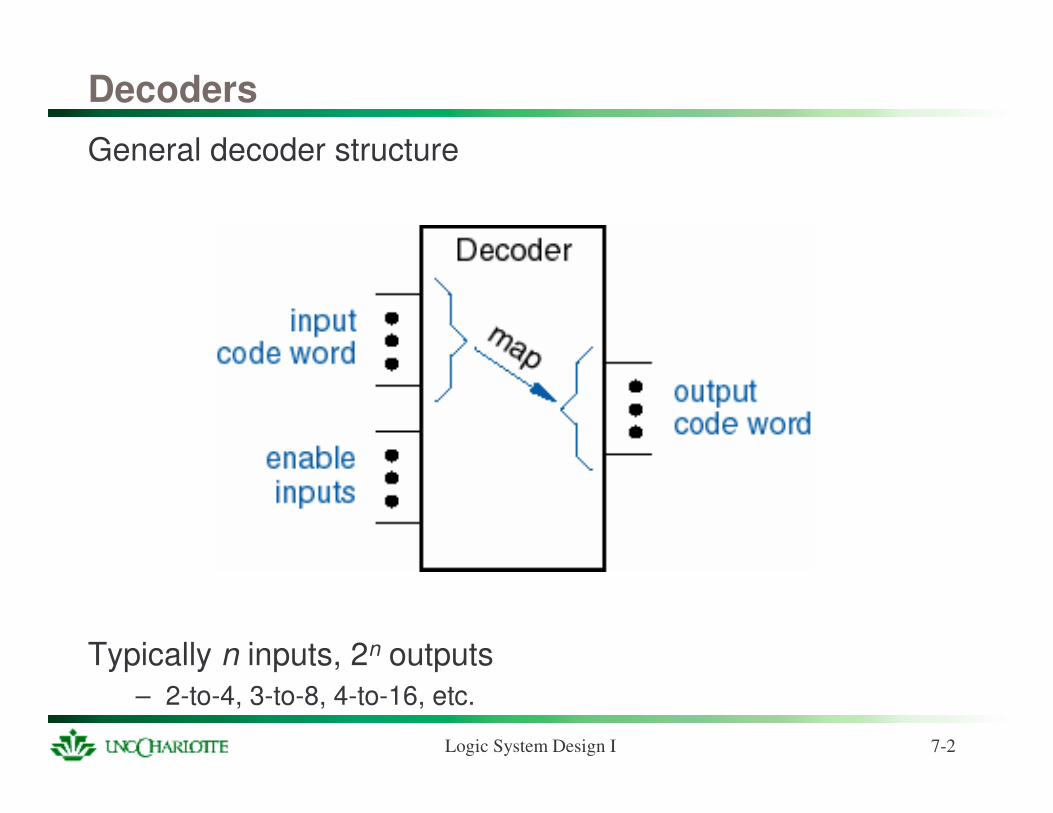
Decoders
General decoder structure
Typically n inputs, 2n outputs– 2-to-4, 3-to-8, 4-to-16, etc.
Logic System Design I 7-3
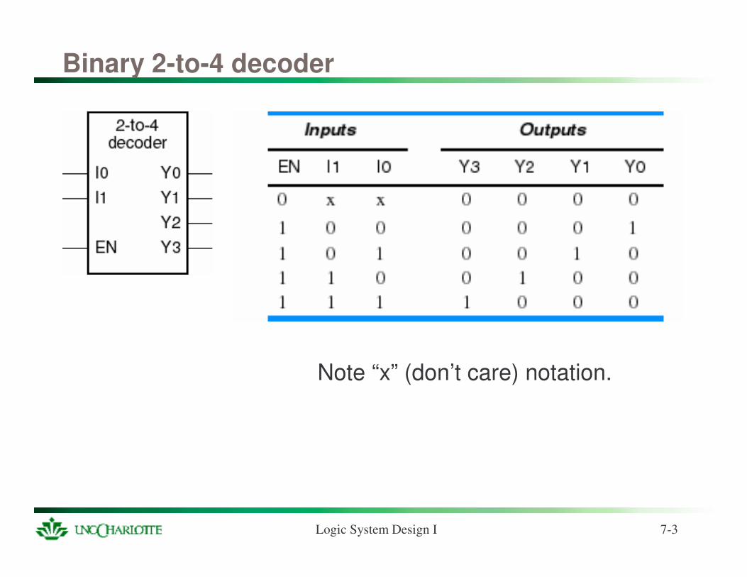
Binary 2-to-4 decoder
Note “x” (don’t care) notation.
Logic System Design I 7-4
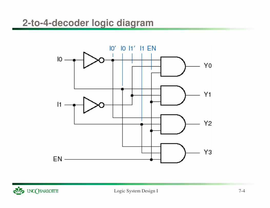
2-to-4-decoder logic diagram
Logic System Design I 7-5
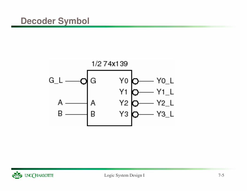
Decoder Symbol
Logic System Design I 7-6
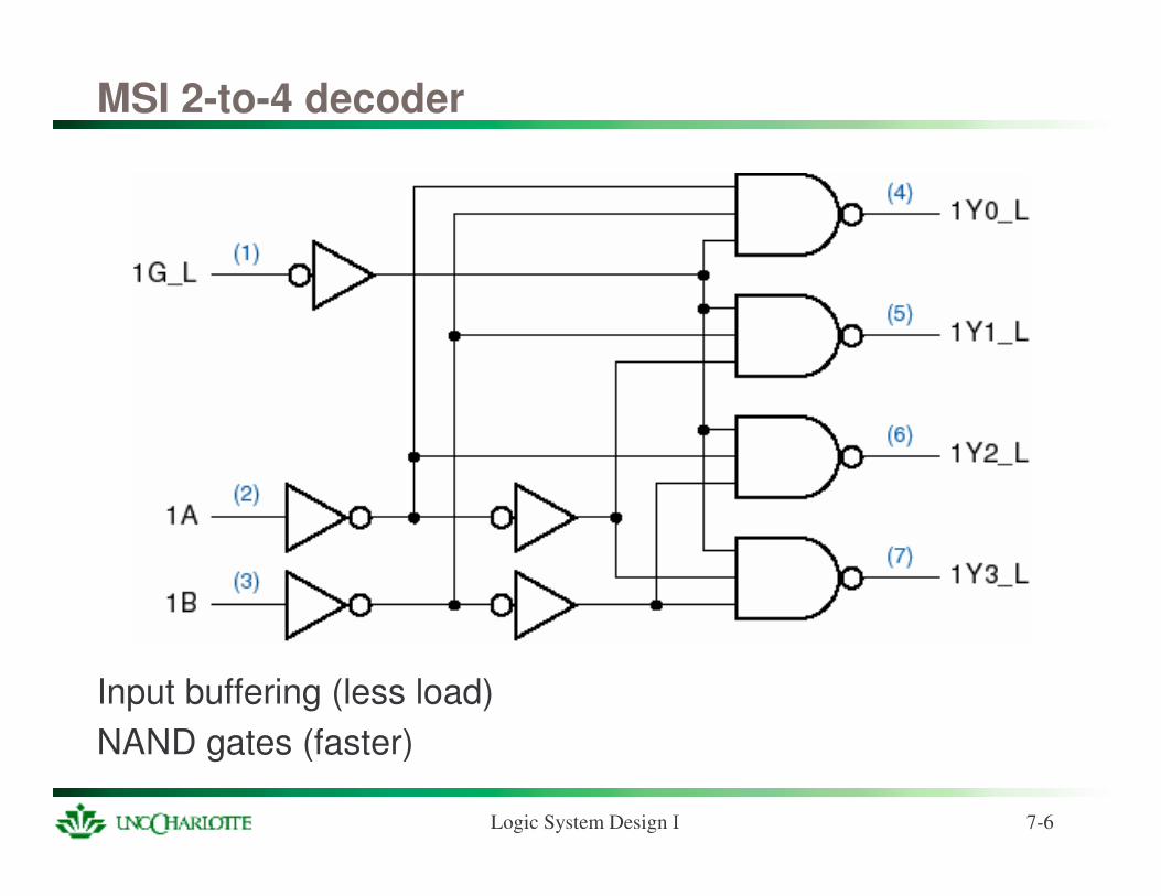
MSI 2-to-4 decoder
Input buffering (less load)NAND gates (faster)
Logic System Design I 7-7
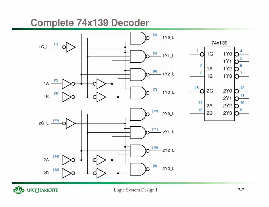
Complete 74x139 Decoder
Logic System Design I 7-8
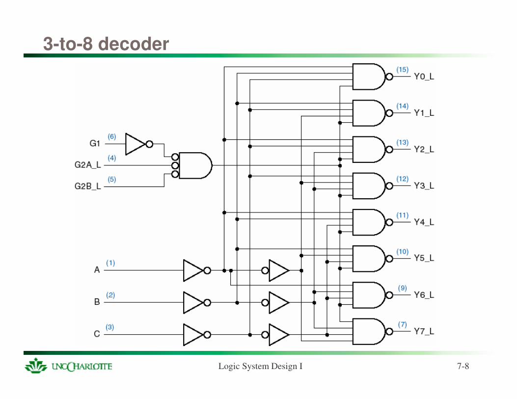
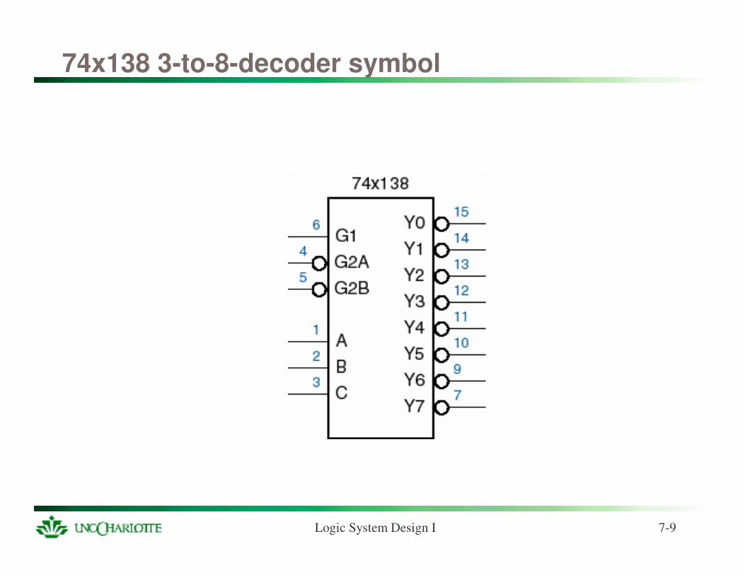
3-to-8 decoder
Logic System Design I 7-9
74x138 3-to-8-decoder symbol
Logic System Design I 7-10
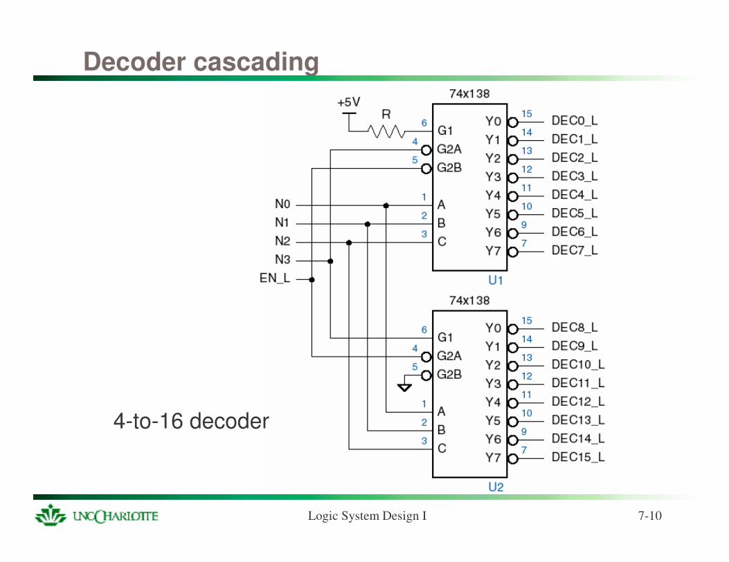
Decoder cascading
4-to-16 decoder
Logic System Design I 7-11
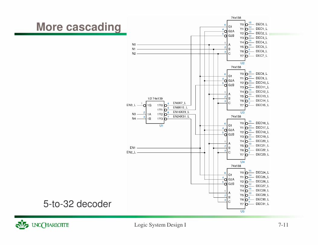
More cascading
5-to-32 decoder
Logic System Design I 7-12
Decoder applications
Microprocessor memory systems– selecting different banks of memory
Microprocessor input/output systems– selecting different devices
Microprocessor instruction decoding– enabling different functional units
Memory chips– enabling different rows of memory depending on address
Logic System Design I 7-13
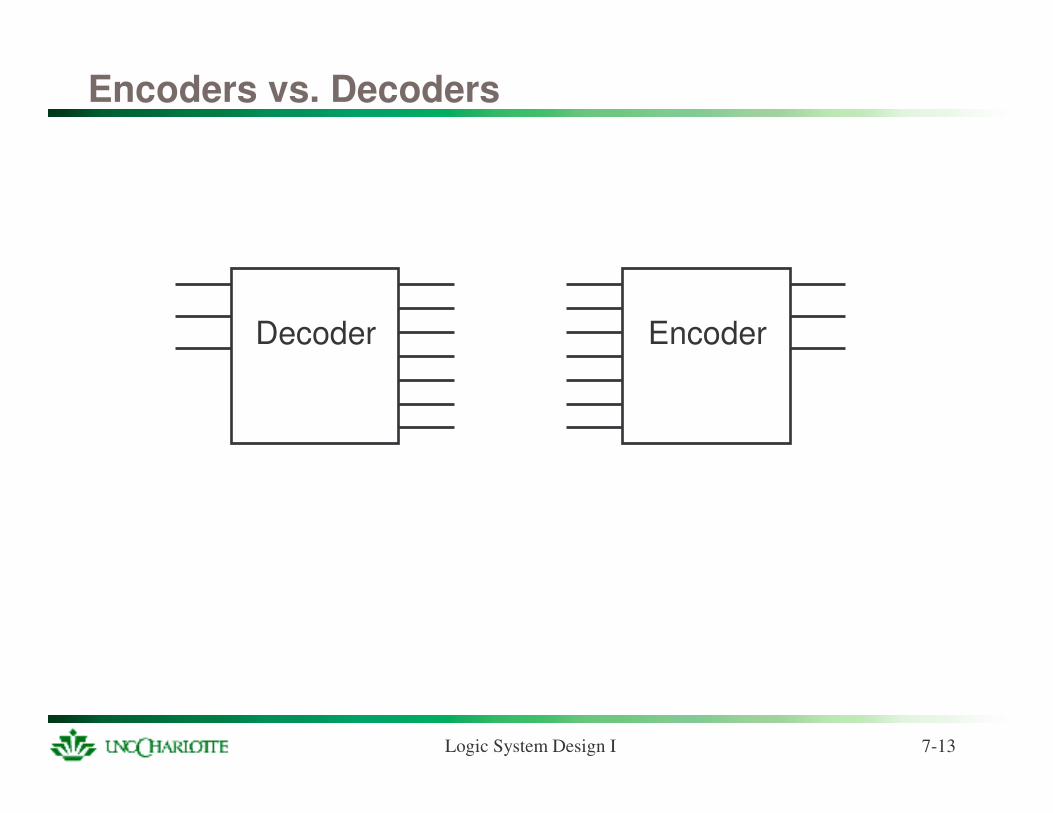
Encoders vs. Decoders
Decoder Encoder
Logic System Design I 7-14
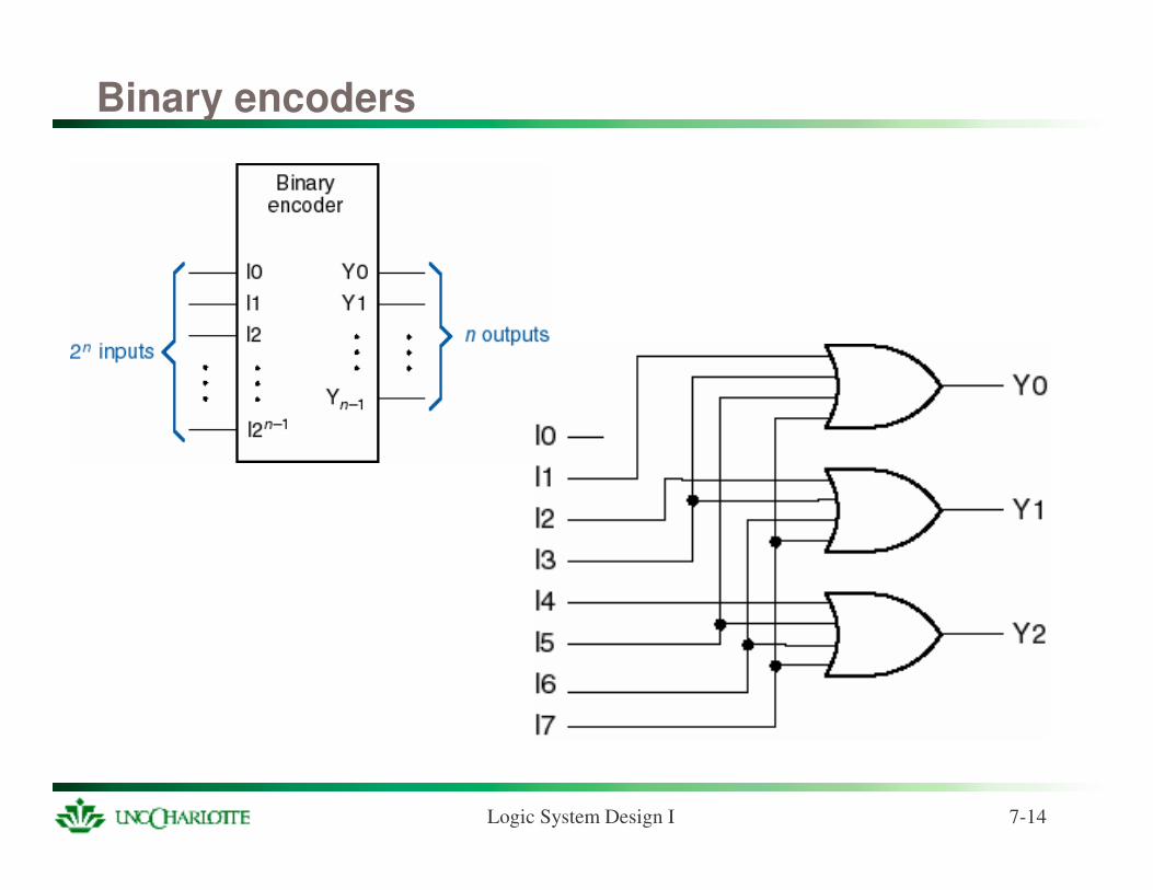
Binary encoders
Logic System Design I 7-15
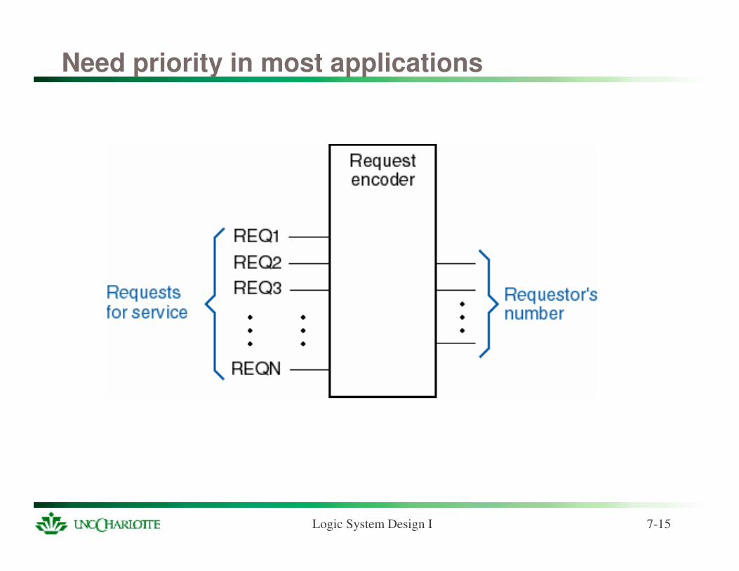
Need priority in most applications
Logic System Design I 7-16
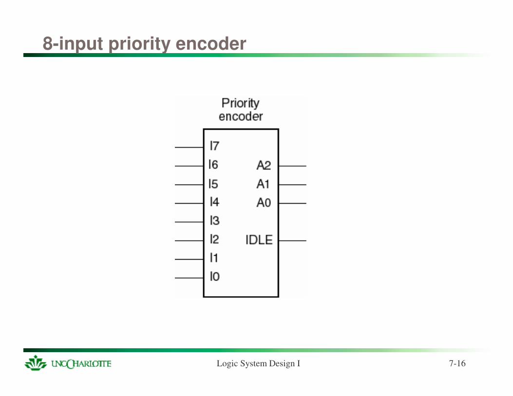
8-input priority encoder
Logic System Design I 7-17
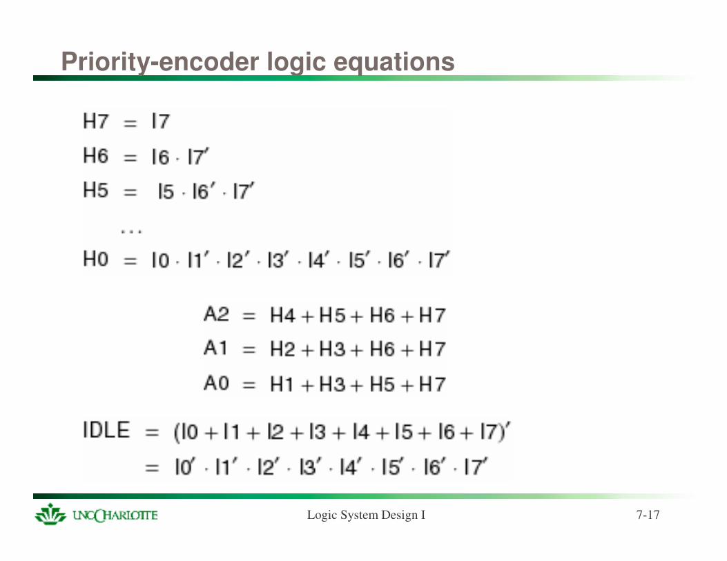
Priority-encoder logic equations
Logic System Design I 7-18
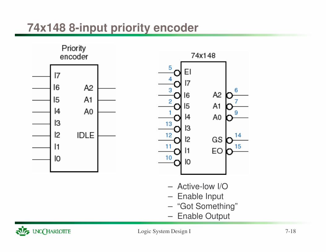
74x148 8-input priority encoder
– Active-low I/O– Enable Input– “Got Something”– Enable Output
Logic System Design I 7-19
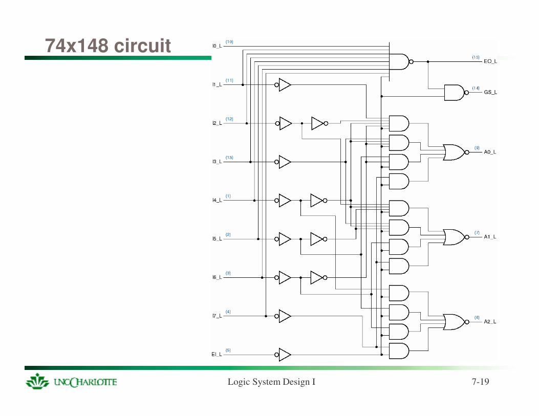
74x148 circuit
Logic System Design I 7-20
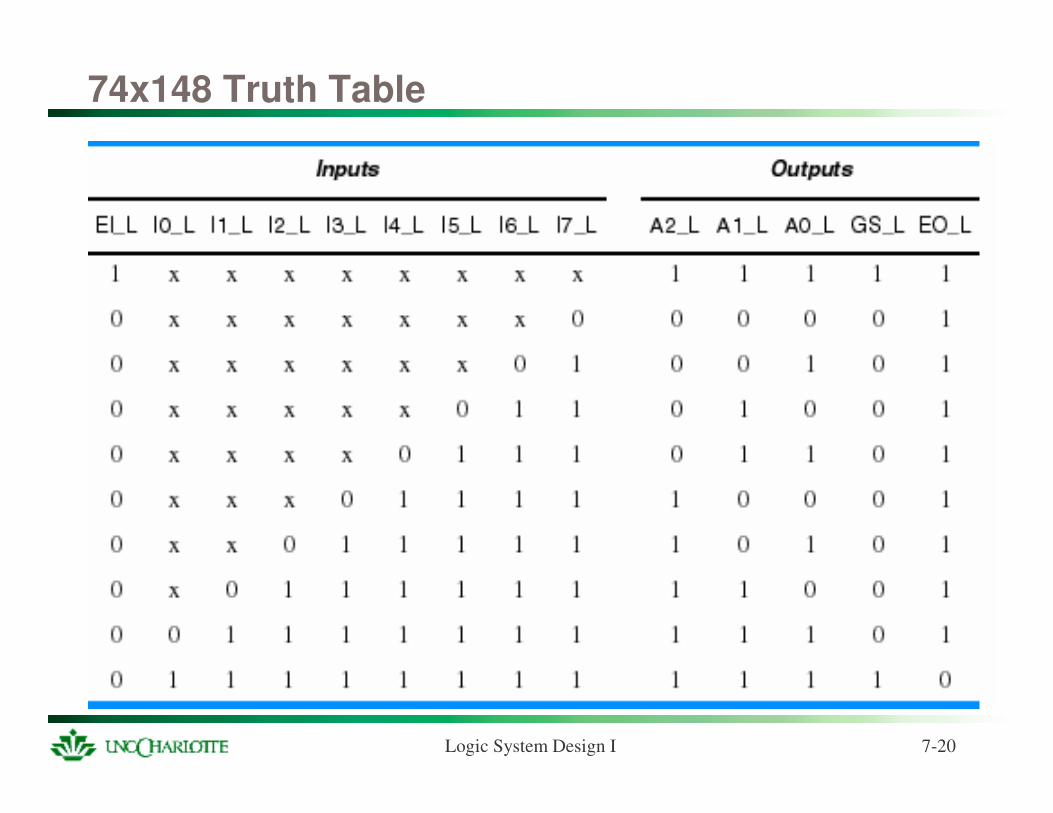
74x148 Truth Table
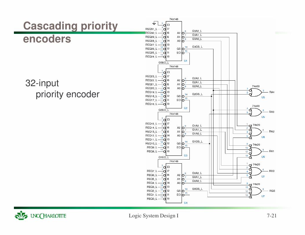
Logic System Design I 7-21
Cascading priority encoders
32-inputpriority encoder