decommissioning programmes decommissioning programmes · bravo hub ba, bc, bp, bd and associated...
TRANSCRIPT

1 5
1
5
Decommissioning Programmes
Decommissioning Programmes
Viking Decommissioning Programmes: VDP2
Viking Satellites KD, LD, AR, Subsea tie-back Vixen VM, Viking
Bravo Hub BA, BC, BP, BD and Associated Infield Pipelines
2 5
Document Control
Approvals
Name Signature Date
Prepared by Cathy Marston Paul Davis
Reviewed by Michael Burnett
Approved by Richard Tocher
Approved by Kate Simpson
Approved by Joe Farrell
Revision Control
Rev Reference Changes / Comments Issue Date
1 COP-SNS-V-XX-X-PM-12-00004 Pre Draft for BEIS 29 Dec 2016
2 COP-SNS-V-XX-X-PM-12-00004 Draft for BEIS 07 Aug 2018
3
4
Distribution List
Name Company No of Copies
Richard Tocher ConocoPhillips 1
Sandra Turin BP 1
3 5
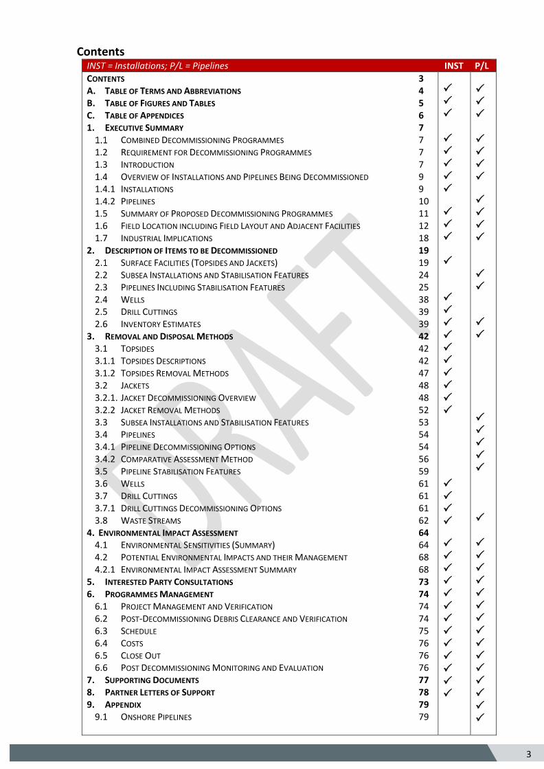
Contents INST = Installations; P/L = Pipelines INST P/L
CONTENTS 3 A. TABLE OF TERMS AND ABBREVIATIONS 4 B. TABLE OF FIGURES AND TABLES 5 C. TABLE OF APPENDICES 6 1. EXECUTIVE SUMMARY 7
COMBINED DECOMMISSIONING PROGRAMMES 7 1.2 REQUIREMENT FOR DECOMMISSIONING PROGRAMMES 7 1.3 INTRODUCTION 7
OVERVIEW OF INSTALLATIONS AND PIPELINES BEING DECOMMISSIONED 9 1.4.1 INSTALLATIONS 9 1.4.2 PIPELINES 10 1.5 SUMMARY OF PROPOSED DECOMMISSIONING PROGRAMMES 11 1.6 FIELD LOCATION INCLUDING FIELD LAYOUT AND ADJACENT FACILITIES 12 1.7 INDUSTRIAL IMPLICATIONS 18
2. DESCRIPTION OF ITEMS TO BE DECOMMISSIONED 19 SURFACE FACILITIES (TOPSIDES AND JACKETS) 19
2.2 SUBSEA INSTALLATIONS AND STABILISATION FEATURES 24 2.3 PIPELINES INCLUDING STABILISATION FEATURES 25 2.4 WELLS 38 2.5 DRILL CUTTINGS 39 2.6 INVENTORY ESTIMATES 39
3. REMOVAL AND DISPOSAL METHODS 42 3.1 TOPSIDES 42 3.1.1 TOPSIDES DESCRIPTIONS 42 3.1.2 TOPSIDES REMOVAL METHODS 47 3.2 JACKETS 48 3.2.1. JACKET DECOMMISSIONING OVERVIEW 48 3.2.2 JACKET REMOVAL METHODS 52 3.3 SUBSEA INSTALLATIONS AND STABILISATION FEATURES 53 3.4 PIPELINES 54 3.4.1 PIPELINE DECOMMISSIONING OPTIONS 54 3.4.2 COMPARATIVE ASSESSMENT METHOD 56 3.5 PIPELINE STABILISATION FEATURES 59 3.6 WELLS 61 3.7 DRILL CUTTINGS 61 3.7.1 DRILL CUTTINGS DECOMMISSIONING OPTIONS 61 3.8 WASTE STREAMS 62
4. ENVIRONMENTAL IMPACT ASSESSMENT 64 4.1 ENVIRONMENTAL SENSITIVITIES (SUMMARY) 64 4.2 POTENTIAL ENVIRONMENTAL IMPACTS AND THEIR MANAGEMENT 68 4.2.1 ENVIRONMENTAL IMPACT ASSESSMENT SUMMARY 68
5. INTERESTED PARTY CONSULTATIONS 73 6. PROGRAMMES MANAGEMENT 74
6.1 PROJECT MANAGEMENT AND VERIFICATION 74 6.2 POST-DECOMMISSIONING DEBRIS CLEARANCE AND VERIFICATION 74 6.3 SCHEDULE 75 6.4 COSTS 76 6.5 CLOSE OUT 76 6.6 POST DECOMMISSIONING MONITORING AND EVALUATION 76
7. SUPPORTING DOCUMENTS 77 8. PARTNER LETTERS OF SUPPORT 78 9. APPENDIX 79
9.1 ONSHORE PIPELINES 79
4 5
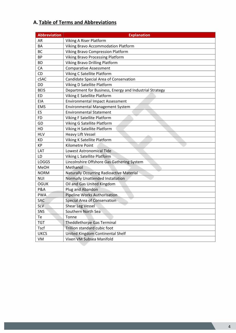
A. Table of Terms and Abbreviations
Abbreviation Explanation
AR Viking A Riser Platform
BA Viking Bravo Accommodation Platform
BC Viking Bravo Compression Platform
BP Viking Bravo Processing Platform
BD Viking Bravo Drilling Platform
CA Comparative Assessment
CD Viking C Satellite Platform
cSAC Candidate Special Area of Conservation
DD Viking D Satellite Platform
BEIS Department for Business, Energy and Industrial Strategy
ED Viking E Satellite Platform
EIA Environmental Impact Assessment
EMS Environmental Management System
ES Environmental Statement
FD Viking F Satellite Platform
GD Viking G Satellite Platform
HD Viking H Satellite Platform
HLV Heavy Lift Vessel
KD Viking K Satellite Platform
KP Kilometre Point
LAT Lowest Astronomical Tide
LD Viking L Satellite Platform
LOGGS Lincolnshire Offshore Gas Gathering System
MeOH Methanol
NORM Naturally Occurring Radioactive Material
NUI Normally Unattended Installation
OGUK Oil and Gas United Kingdom
P&A Plug and Abandon
PWA Pipeline Works Authorisation
SAC Special Area of Conservation
SLV Shear Leg Vessel
SNS Southern North Sea
Te Tonne
TGT Theddlethorpe Gas Terminal
Tscf Trillion standard cubic foot
UKCS United Kingdom Continental Shelf
VM Vixen VM Subsea Manifold
5 5
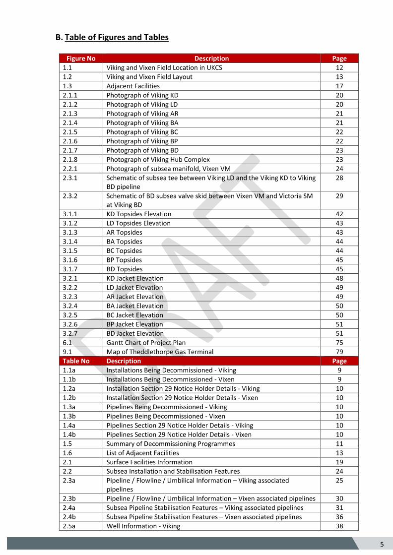
B. Table of Figures and Tables
Figure No Description Page
1.1 Viking and Vixen Field Location in UKCS 12
1.2 Viking and Vixen Field Layout 13
1.3 Adjacent Facilities 17
2.1.1 Photograph of Viking KD 20
2.1.2 Photograph of Viking LD 20
2.1.3 Photograph of Viking AR 21
2.1.4 Photograph of Viking BA 21
2.1.5 Photograph of Viking BC 22
2.1.6 Photograph of Viking BP 22
2.1.7 Photograph of Viking BD 23
2.1.8 Photograph of Viking Hub Complex 23
2.2.1 Photograph of subsea manifold, Vixen VM 24
2.3.1 Schematic of subsea tee between Viking LD and the Viking KD to Viking BD pipeline
28
2.3.2 Schematic of BD subsea valve skid between Vixen VM and Victoria SM at Viking BD
29
3.1.1 KD Topsides Elevation 42
3.1.2 LD Topsides Elevation 43
3.1.3 AR Topsides 43
3.1.4 BA Topsides 44
3.1.5 BC Topsides 44
3.1.6 BP Topsides 45
3.1.7 BD Topsides 45
3.2.1 KD Jacket Elevation 48
3.2.2 LD Jacket Elevation 49
3.2.3 AR Jacket Elevation 49
3.2.4 BA Jacket Elevation 50
3.2.5 BC Jacket Elevation 50
3.2.6 BP Jacket Elevation 51
3.2.7 BD Jacket Elevation 51
6.1 Gantt Chart of Project Plan 75
9.1 Map of Theddlethorpe Gas Terminal 79
Table No Description Page
1.1a Installations Being Decommissioned - Viking 9
1.1b Installations Being Decommissioned - Vixen 9
1.2a Installation Section 29 Notice Holder Details - Viking 10
1.2b Installation Section 29 Notice Holder Details - Vixen 10
1.3a Pipelines Being Decommissioned - Viking 10
1.3b Pipelines Being Decommissioned - Vixen 10
1.4a Pipelines Section 29 Notice Holder Details - Viking 10
1.4b Pipelines Section 29 Notice Holder Details - Vixen 10
1.5 Summary of Decommissioning Programmes 11
1.6 List of Adjacent Facilities 13
2.1 Surface Facilities Information 19
2.2 Subsea Installation and Stabilisation Features 24
2.3a Pipeline / Flowline / Umbilical Information – Viking associated pipelines
25
2.3b Pipeline / Flowline / Umbilical Information – Vixen associated pipelines 30
2.4a Subsea Pipeline Stabilisation Features – Viking associated pipelines 31
2.4b Subsea Pipeline Stabilisation Features – Vixen associated pipelines 36
2.5a Well Information - Viking 38
6 5
2.5b Well Information - Vixen 38
2.6 Drill Cuttings Pile Information 39
2.7a Installation Material Functional Category Summary - Viking 39
2.7b Installation Material Functional Category Summary - Vixen 39
2.8a Pipeline and Mattress Material Functional Category Summary - Viking 40
2.8b Pipeline and Mattress Material Functional Category Summary - Vixen 41
3.1 Cleaning of Topsides for Removal 46
3.2 Topsides Removal Methods 47
3.3 Jacket Removal Methods 52
3.4a Subsea Installations and Stabilisation features - Viking 53
3.4b Subsea Installations and Stabilisation features - Vixen 53
3.5a Pipeline or Pipeline Groups / Decommissioning Options - Viking 54
3.5b Pipeline or Pipeline Groups / Decommissioning Options - Vixen 55
3.6a Outcomes of Comparative Assessment - Viking 57
3.6b Outcomes of Comparative Assessment - Vixen 58
3.7a Pipeline Stabilisation Features - Viking 59
3.7b Pipeline Stabilisation Features - Vixen 60
3.8 Well Plug and Abandonment 61
3.9 Waste Stream Management Methods 62
3.10a Inventory Disposition - Viking 63
3.10b Inventory Disposition - Vixen 63
4.1 Environmental Sensitivities 64
4.2 Environmental Impact Management 68
5.1 Summary of Stakeholder Comments 73
6.1 Provisional Decommissioning Programmes Costs 76
7.1 Supporting Documents 77
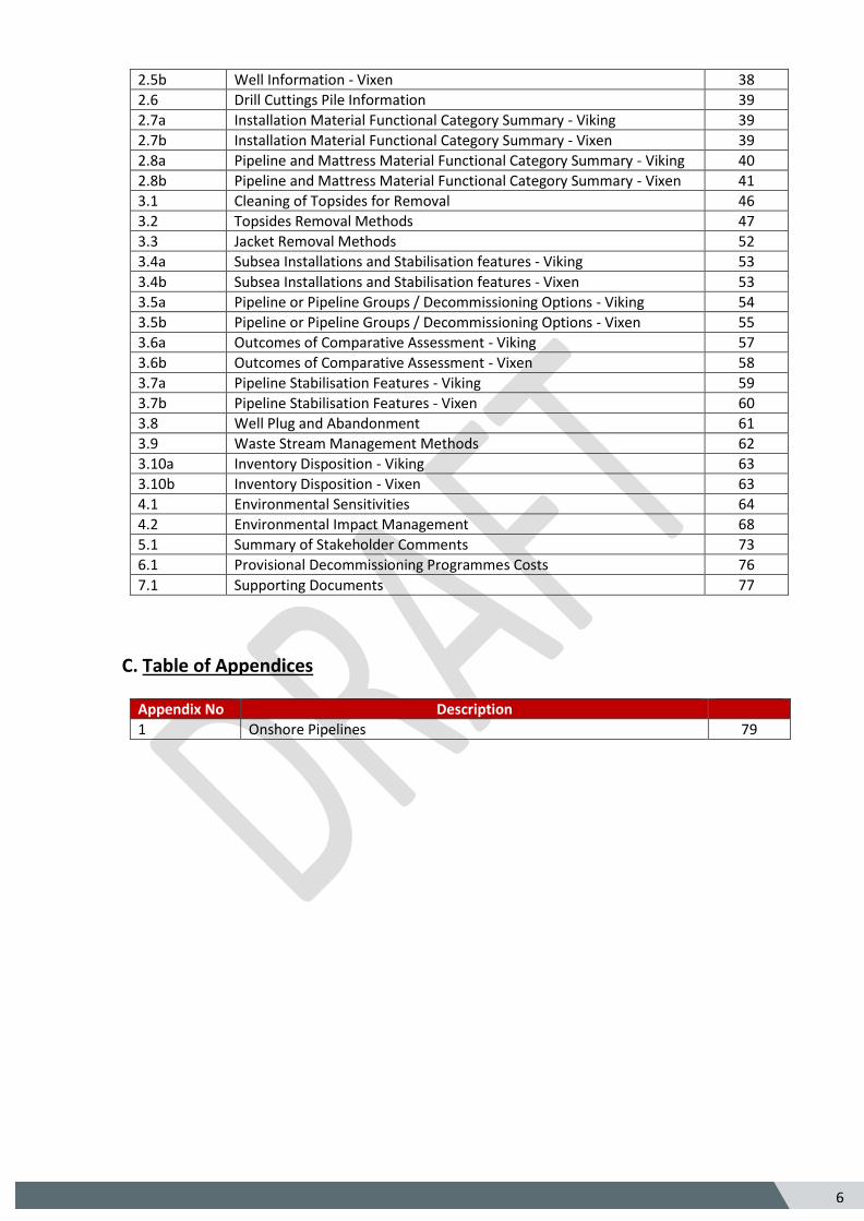
C. Table of Appendices
Appendix No Description
1 Onshore Pipelines 79
7 5
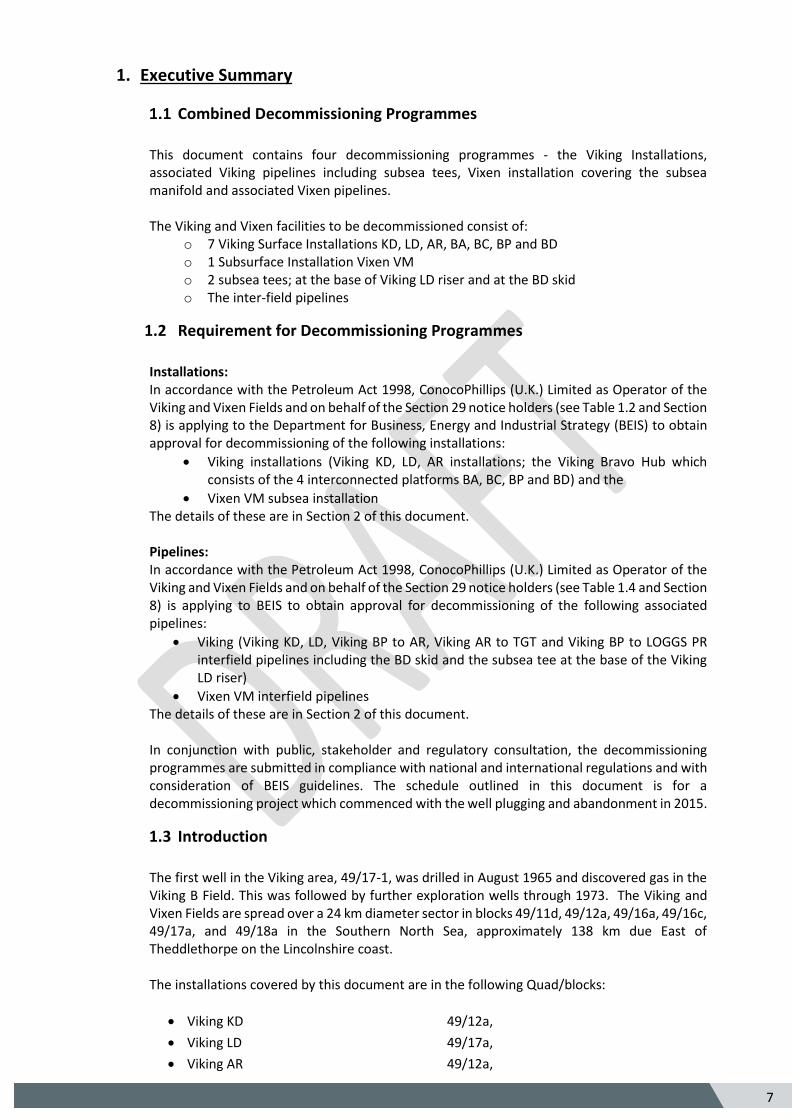
1. Executive Summary
Combined Decommissioning Programmes
This document contains four decommissioning programmes - the Viking Installations, associated Viking pipelines including subsea tees, Vixen installation covering the subsea manifold and associated Vixen pipelines. The Viking and Vixen facilities to be decommissioned consist of:
o 7 Viking Surface Installations KD, LD, AR, BA, BC, BP and BD o 1 Subsurface Installation Vixen VM o 2 subsea tees; at the base of Viking LD riser and at the BD skid o The inter-field pipelines
1.2 Requirement for Decommissioning Programmes
Installations: In accordance with the Petroleum Act 1998, ConocoPhillips (U.K.) Limited as Operator of the Viking and Vixen Fields and on behalf of the Section 29 notice holders (see Table 1.2 and Section 8) is applying to the Department for Business, Energy and Industrial Strategy (BEIS) to obtain approval for decommissioning of the following installations:
• Viking installations (Viking KD, LD, AR installations; the Viking Bravo Hub which consists of the 4 interconnected platforms BA, BC, BP and BD) and the
• Vixen VM subsea installation The details of these are in Section 2 of this document. Pipelines: In accordance with the Petroleum Act 1998, ConocoPhillips (U.K.) Limited as Operator of the Viking and Vixen Fields and on behalf of the Section 29 notice holders (see Table 1.4 and Section 8) is applying to BEIS to obtain approval for decommissioning of the following associated pipelines:
• Viking (Viking KD, LD, Viking BP to AR, Viking AR to TGT and Viking BP to LOGGS PR interfield pipelines including the BD skid and the subsea tee at the base of the Viking LD riser)
• Vixen VM interfield pipelines The details of these are in Section 2 of this document. In conjunction with public, stakeholder and regulatory consultation, the decommissioning programmes are submitted in compliance with national and international regulations and with consideration of BEIS guidelines. The schedule outlined in this document is for a decommissioning project which commenced with the well plugging and abandonment in 2015.
1.3 Introduction
The first well in the Viking area, 49/17-1, was drilled in August 1965 and discovered gas in the Viking B Field. This was followed by further exploration wells through 1973. The Viking and Vixen Fields are spread over a 24 km diameter sector in blocks 49/11d, 49/12a, 49/16a, 49/16c, 49/17a, and 49/18a in the Southern North Sea, approximately 138 km due East of Theddlethorpe on the Lincolnshire coast. The installations covered by this document are in the following Quad/blocks:
• Viking KD 49/12a,
• Viking LD 49/17a,
• Viking AR 49/12a,
8 5
• Viking Bravo Hub (BA, BC, BP and BD) 49/17a,
• Vixen VM 49/17a.
Production from the Viking reservoirs commenced in 1972 from two manned multi jacket bridge linked complexes Viking A (Alpha) and Viking B (Bravo). Gas export from Viking A and B was combined at the Viking Riser platform (AR) prior to being exported to the Theddlethorpe Gas Terminal (TGT) via a 28” export pipeline. Normally Unattended Installations (NUI) were subsequently tied back to the two manned complexes as follows:
• 1974 – 1975, Viking CD, DD, ED, GD, HD tied back to Viking B complex
• 1975 Viking FD tied back to Viking A complex
• 1984 Victor JD tied back to Viking B complex
• 1995 Victor JM (subsea) tied-back to Victor JD
• 1998 Viking KD and LD tied back to Viking B complex
• 2000 Vixen VM (subsea) tied back to Viking B complex
• 2008 Victoria SM (subsea) tied back to Viking B complex
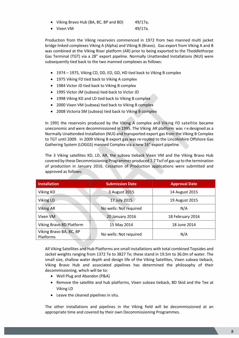
In 1991 the reservoirs produced by the Viking A complex and Viking FD satellite became uneconomic and were decommissioned in 1995. The Viking AR platform was r e designed as a Normally Unattended Installation (NUI) and transported export gas from the Viking B Complex to TGT until 2009. In 2009 Viking B export gas was re-routed to the Lincolnshire Offshore Gas Gathering System (LOGGS) manned Complex via a new 16” export pipeline. The 3 Viking satellites KD, LD, AR, the subsea tieback Vixen VM and the Viking Bravo Hub covered by these Decommissioning Programmes produced 1.7 Tscf of gas up to the termination of production in January 2016. Cessation of Production applications were submitted and approved as follows:
Installation Submission Date Approval Date
Viking KD 3 August 2015 14 August 2015
Viking LD 17 July 2015 19 August 2015
Viking AR No wells: Not required N/A
Vixen VM 20 January 2016 18 February 2016
Viking Bravo BD Platform 15 May 2014 18 June 2014
Viking Bravo BA, BC, BP Platforms
No wells: Not required N/A
All Viking Satellites and Hub Platforms are small installations with total combined Topsides and Jacket weights ranging from 1372 Te to 3827 Te; these stand in 19.5m to 36.0m of water. The small size, shallow water depth and design life of the Viking Satellites, Vixen subsea tieback, Viking Bravo Hub and associated pipelines has determined the philosophy of their decommissioning, which will be to:
• Well Plug and Abandon (P&A)
• Remove the satellite and hub platforms, Vixen subsea tieback, BD Skid and the Tee at
Viking LD
• Leave the cleaned pipelines in situ.
The other installations and pipelines in the Viking field will be decommissioned at an appropriate time and covered by their own Decommissioning Programmes.
9 5
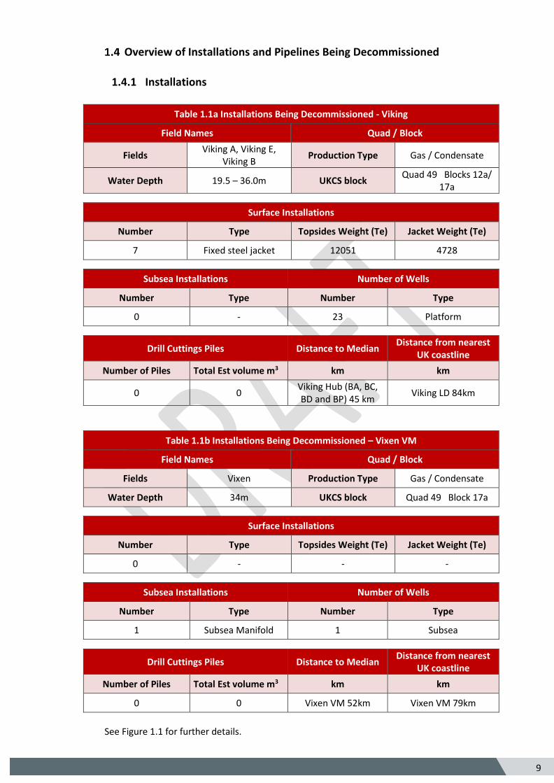
Overview of Installations and Pipelines Being Decommissioned
1.4.1 Installations
Table 1.1a Installations Being Decommissioned - Viking
Field Names Quad / Block
Fields Viking A, Viking E,
Viking B Production Type Gas / Condensate
Water Depth 19.5 – 36.0m UKCS block Quad 49 Blocks 12a/
17a
Surface Installations
Number Type Topsides Weight (Te) Jacket Weight (Te)
7 Fixed steel jacket 12051 4728
Subsea Installations Number of Wells
Number Type Number Type
0 - 23 Platform
Drill Cuttings Piles Distance to Median Distance from nearest
UK coastline
Number of Piles Total Est volume m3 km km
0 0 Viking Hub (BA, BC, BD and BP) 45 km
Viking LD 84km
Table 1.1b Installations Being Decommissioned – Vixen VM
Field Names Quad / Block
Fields Vixen Production Type Gas / Condensate
Water Depth 34m UKCS block Quad 49 Block 17a
Surface Installations
Number Type Topsides Weight (Te) Jacket Weight (Te)
0 - - -
Subsea Installations Number of Wells
Number Type Number Type
1 Subsea Manifold 1 Subsea
Drill Cuttings Piles Distance to Median Distance from nearest
UK coastline
Number of Piles Total Est volume m3 km km
0 0 Vixen VM 52km Vixen VM 79km
See Figure 1.1 for further details.
10
5
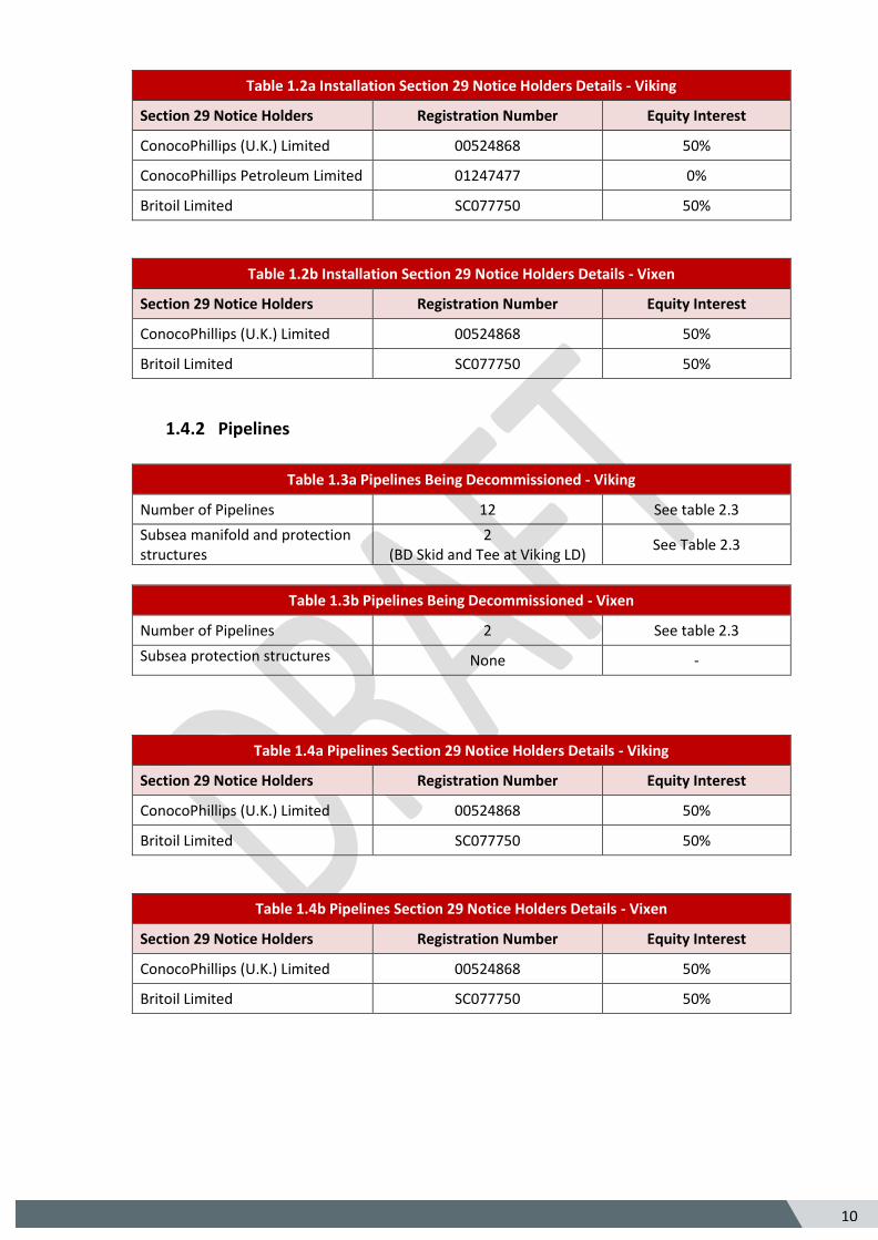
Table 1.2a Installation Section 29 Notice Holders Details - Viking
Section 29 Notice Holders Registration Number Equity Interest
ConocoPhillips (U.K.) Limited 00524868 50%
ConocoPhillips Petroleum Limited 01247477 0%
Britoil Limited SC077750 50%
Table 1.2b Installation Section 29 Notice Holders Details - Vixen
Section 29 Notice Holders Registration Number Equity Interest
ConocoPhillips (U.K.) Limited 00524868 50%
Britoil Limited SC077750 50%
1.4.2 Pipelines
Table 1.3a Pipelines Being Decommissioned - Viking
Number of Pipelines 12 See table 2.3
Subsea manifold and protection structures
2 (BD Skid and Tee at Viking LD)
See Table 2.3
Table 1.3b Pipelines Being Decommissioned - Vixen
Number of Pipelines 2 See table 2.3
Subsea protection structures None -
Table 1.4a Pipelines Section 29 Notice Holders Details - Viking
Section 29 Notice Holders Registration Number Equity Interest
ConocoPhillips (U.K.) Limited 00524868 50%
Britoil Limited SC077750 50%
Table 1.4b Pipelines Section 29 Notice Holders Details - Vixen
Section 29 Notice Holders Registration Number Equity Interest
ConocoPhillips (U.K.) Limited 00524868 50%
Britoil Limited SC077750 50%
11
5
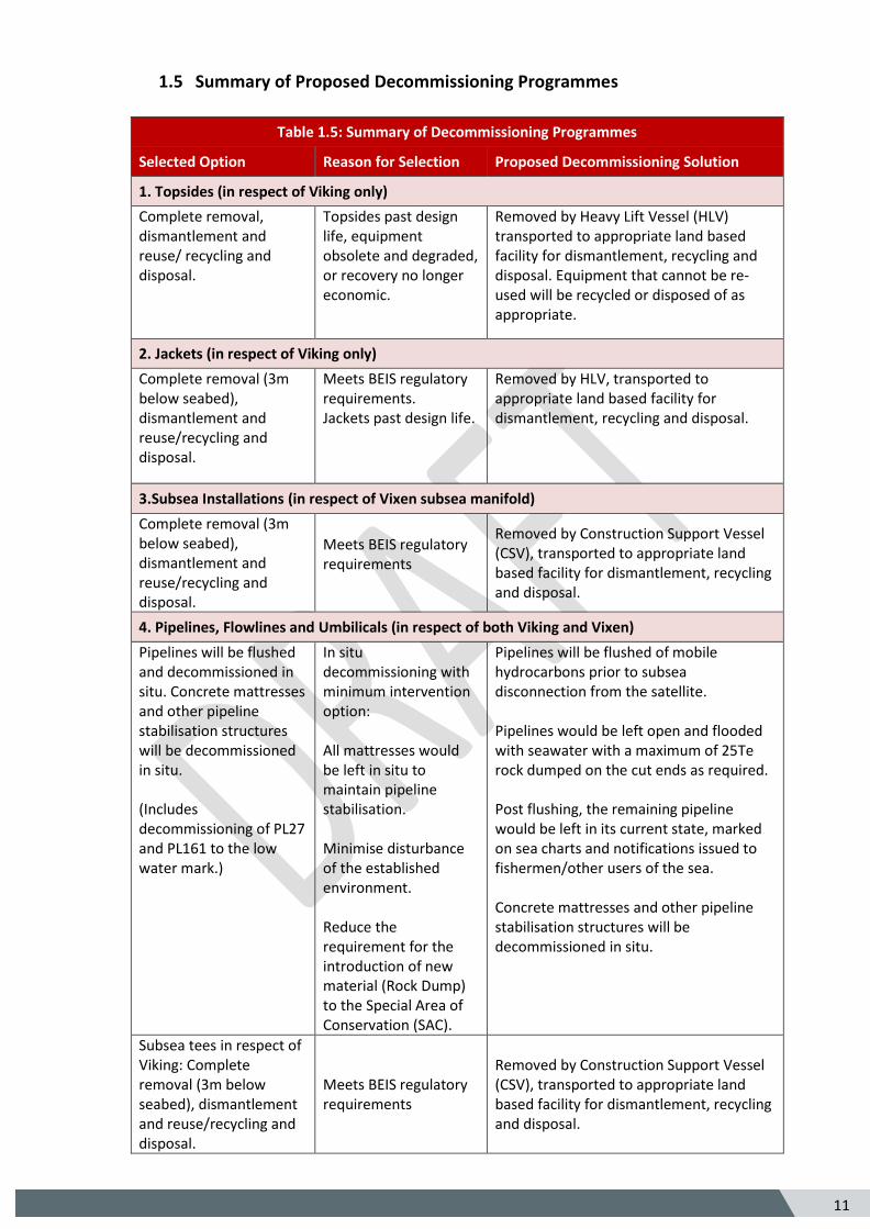
1.5 Summary of Proposed Decommissioning Programmes
Table 1.5: Summary of Decommissioning Programmes
Selected Option Reason for Selection Proposed Decommissioning Solution
1. Topsides (in respect of Viking only)
Complete removal, dismantlement and reuse/ recycling and disposal.
Topsides past design life, equipment obsolete and degraded, or recovery no longer economic.
Removed by Heavy Lift Vessel (HLV) transported to appropriate land based facility for dismantlement, recycling and disposal. Equipment that cannot be re-used will be recycled or disposed of as appropriate.
2. Jackets (in respect of Viking only)
Complete removal (3m below seabed), dismantlement and reuse/recycling and disposal.
Meets BEIS regulatory requirements. Jackets past design life.
Removed by HLV, transported to appropriate land based facility for dismantlement, recycling and disposal.
3.Subsea Installations (in respect of Vixen subsea manifold)
Complete removal (3m below seabed), dismantlement and reuse/recycling and disposal.
Meets BEIS regulatory requirements
Removed by Construction Support Vessel (CSV), transported to appropriate land based facility for dismantlement, recycling and disposal.
4. Pipelines, Flowlines and Umbilicals (in respect of both Viking and Vixen)
Pipelines will be flushed and decommissioned in situ. Concrete mattresses and other pipeline stabilisation structures will be decommissioned in situ. (Includes decommissioning of PL27 and PL161 to the low water mark.)
In situ decommissioning with minimum intervention option: All mattresses would be left in situ to maintain pipeline stabilisation. Minimise disturbance of the established environment. Reduce the requirement for the introduction of new material (Rock Dump) to the Special Area of Conservation (SAC).
Pipelines will be flushed of mobile hydrocarbons prior to subsea disconnection from the satellite. Pipelines would be left open and flooded with seawater with a maximum of 25Te rock dumped on the cut ends as required. Post flushing, the remaining pipeline would be left in its current state, marked on sea charts and notifications issued to fishermen/other users of the sea. Concrete mattresses and other pipeline stabilisation structures will be decommissioned in situ.
Subsea tees in respect of Viking: Complete removal (3m below seabed), dismantlement and reuse/recycling and disposal.
Meets BEIS regulatory requirements
Removed by Construction Support Vessel (CSV), transported to appropriate land based facility for dismantlement, recycling and disposal.
12
5
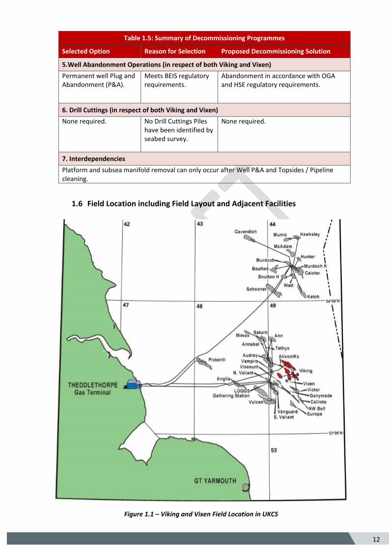
Table 1.5: Summary of Decommissioning Programmes
Selected Option Reason for Selection Proposed Decommissioning Solution
5.Well Abandonment Operations (in respect of both Viking and Vixen)
Permanent well Plug and Abandonment (P&A).
Meets BEIS regulatory requirements.
Abandonment in accordance with OGA and HSE regulatory requirements.
6. Drill Cuttings (in respect of both Viking and Vixen)
None required. No Drill Cuttings Piles have been identified by seabed survey.
None required.
7. Interdependencies
Platform and subsea manifold removal can only occur after Well P&A and Topsides / Pipeline cleaning.
1.6 Field Location including Field Layout and Adjacent Facilities
Figure 1.1 – Viking and Vixen Field Location in UKCS
13
5
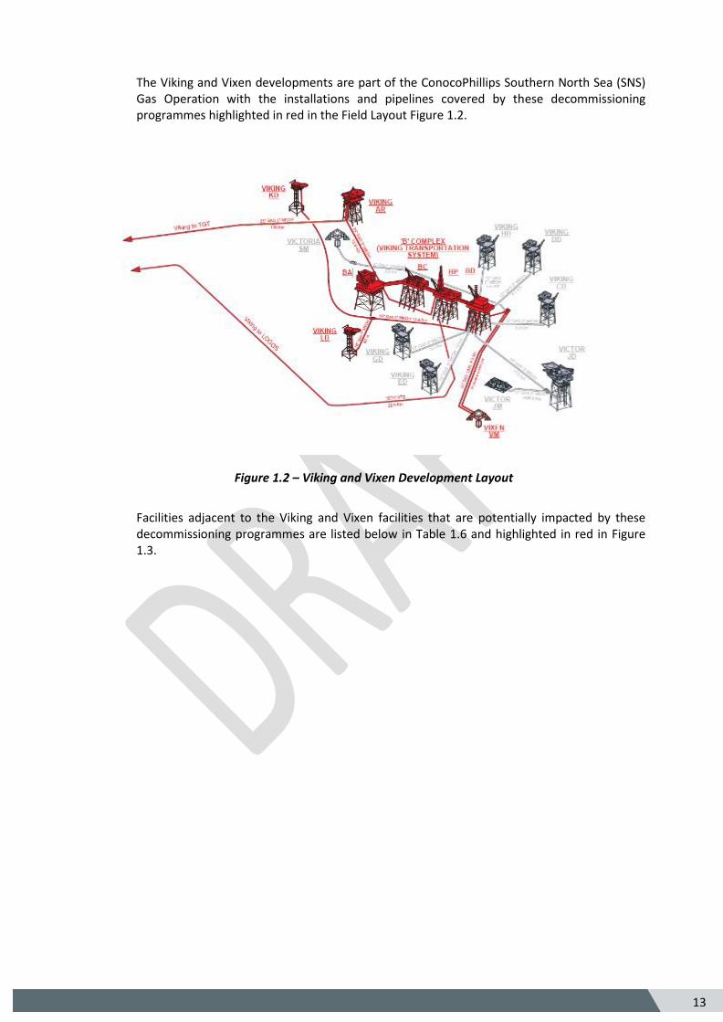
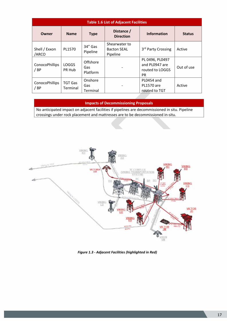
The Viking and Vixen developments are part of the ConocoPhillips Southern North Sea (SNS) Gas Operation with the installations and pipelines covered by these decommissioning programmes highlighted in red in the Field Layout Figure 1.2.
Figure 1.2 – Viking and Vixen Development Layout
Facilities adjacent to the Viking and Vixen facilities that are potentially impacted by these decommissioning programmes are listed below in Table 1.6 and highlighted in red in Figure 1.3.
14
5
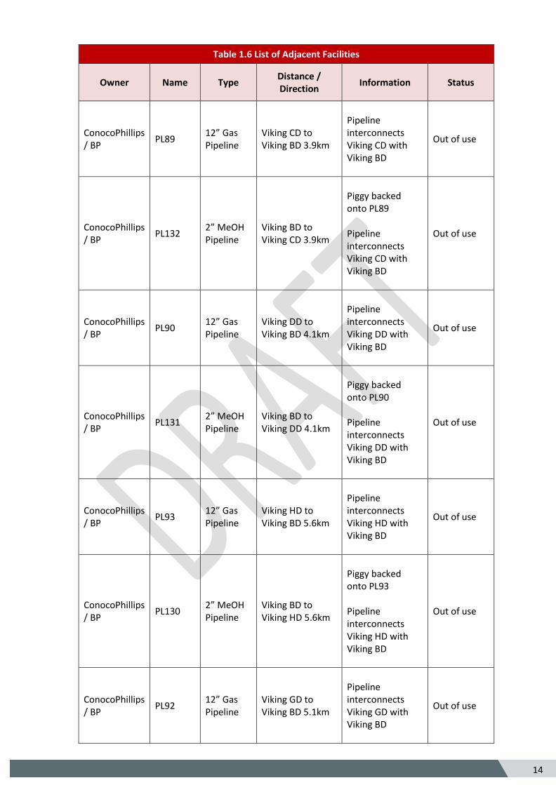
Table 1.6 List of Adjacent Facilities
Owner Name Type Distance / Direction
Information Status
ConocoPhillips / BP
PL89 12” Gas Pipeline
Viking CD to Viking BD 3.9km
Pipeline interconnects Viking CD with Viking BD
Out of use
ConocoPhillips / BP
PL132 2” MeOH Pipeline
Viking BD to Viking CD 3.9km
Piggy backed onto PL89 Pipeline interconnects Viking CD with Viking BD
Out of use
ConocoPhillips / BP
PL90 12” Gas Pipeline
Viking DD to Viking BD 4.1km
Pipeline interconnects Viking DD with Viking BD
Out of use
ConocoPhillips / BP
PL131 2” MeOH Pipeline
Viking BD to Viking DD 4.1km
Piggy backed onto PL90 Pipeline interconnects Viking DD with Viking BD
Out of use
ConocoPhillips / BP
PL93 12” Gas Pipeline
Viking HD to Viking BD 5.6km
Pipeline interconnects Viking HD with Viking BD
Out of use
ConocoPhillips / BP
PL130 2” MeOH Pipeline
Viking BD to Viking HD 5.6km
Piggy backed onto PL93 Pipeline interconnects Viking HD with Viking BD
Out of use
ConocoPhillips / BP
PL92 12” Gas Pipeline
Viking GD to Viking BD 5.1km
Pipeline interconnects Viking GD with Viking BD
Out of use
15
5
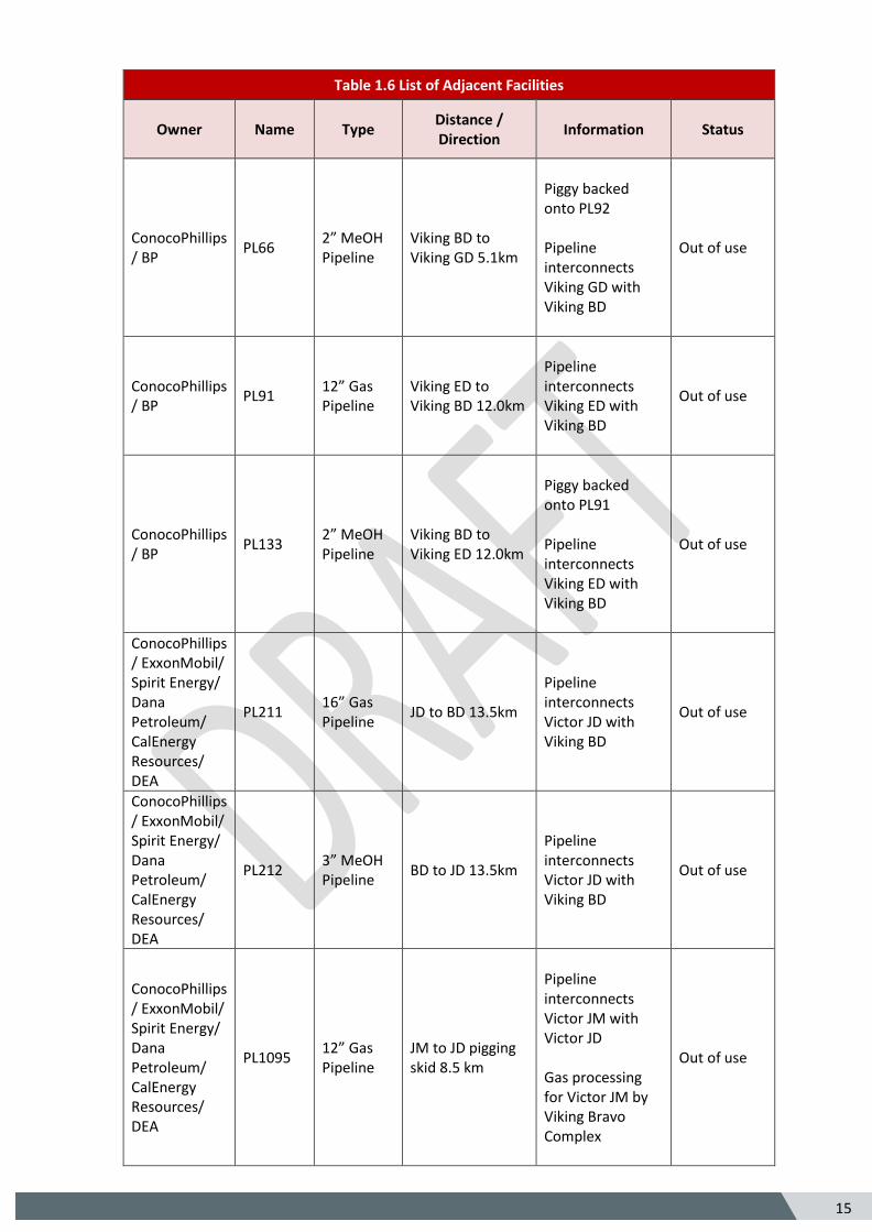
Table 1.6 List of Adjacent Facilities
Owner Name Type Distance / Direction
Information Status
ConocoPhillips / BP
PL66 2” MeOH Pipeline
Viking BD to Viking GD 5.1km
Piggy backed onto PL92 Pipeline interconnects Viking GD with Viking BD
Out of use
ConocoPhillips / BP
PL91 12” Gas Pipeline
Viking ED to Viking BD 12.0km
Pipeline interconnects Viking ED with Viking BD
Out of use
ConocoPhillips / BP
PL133 2” MeOH Pipeline
Viking BD to Viking ED 12.0km
Piggy backed onto PL91 Pipeline interconnects Viking ED with Viking BD
Out of use
ConocoPhillips / ExxonMobil/ Spirit Energy/ Dana Petroleum/ CalEnergy Resources/ DEA
PL211 16” Gas Pipeline
JD to BD 13.5km
Pipeline interconnects Victor JD with Viking BD
Out of use
ConocoPhillips / ExxonMobil/ Spirit Energy/ Dana Petroleum/ CalEnergy Resources/ DEA
PL212 3” MeOH Pipeline
BD to JD 13.5km
Pipeline interconnects Victor JD with Viking BD
Out of use
ConocoPhillips / ExxonMobil/ Spirit Energy/ Dana Petroleum/ CalEnergy Resources/ DEA
PL1095 12” Gas Pipeline
JM to JD pigging skid 8.5 km
Pipeline interconnects Victor JM with Victor JD Gas processing for Victor JM by Viking Bravo Complex
Out of use

16
5
Table 1.6 List of Adjacent Facilities
Owner Name Type Distance / Direction
Information Status
ConocoPhillips / ExxonMobil/ Spirit Energy/ Dana Petroleum/ CalEnergy Resources/ DEA
PL1096 3” MeOH Pipeline
JD to JM 8.5km
Pipeline interconnects Victor JM with Victor JD
Out of use
ConocoPhillips / ExxonMobil/ Spirit Energy/ Dana Petroleum/ CalEnergy Resources/ DEA
UM1 Umbilical JD to JM 8.5km Umbilical from Victor JD to Victor JM
Out of use
Verus Petroleum
Victoria SM
Subsea Manifold
SM to BD 3.8km
Gas processing for Victoria SM by Viking Bravo Complex
Out of use
Verus Petroleum
PL2526 6” Gas Pipeline
Victoria SM to Viking BD 3.8km
Crosses over PL90 & PL93
Out of use
Verus Petroleum
PLU2527 Umbilical Viking BD to Victoria SM 3.8km
Crosses over PL90 & PL93
Out of use
Spirit Energy PL0947 12” Gas Pipeline
ANN XM to LOGGS PR
3rd Party Crossing Out of use
Spirit Energy PL0496 20” Gas Pipeline
Audrey to LOGGS PP Pipeline
3rd Party Crossing Active
Spirit Energy PL0497 3” MeOH Pipeline
LOGGS PP to Audrey Pipeline
3rd Party Crossing Active
Shell / Mobil Exxon
PL1170 3.5” Glycol Pipeline
Bacton to Clipper PT
3rd Party Crossing Active
Shell / Mobil Exxon
PL632 24” Gas Pipeline
Clipper PT to Bacton
3rd Party Crossing Active
Perenco / ENGIE
PL253 24” Gas Pipeline
Esmond to Bacton
3rd Party Crossing Active
ConocoPhillips / BP
PL0454 24” Gas Pipeline
LOGGS PP to TGT 3rd Party Crossing Active
ConocoPhillips / BP
PL0455 4” MeOH Pipeline
TGT to LOGGS PP 3rd Party Crossing Active
17
5
Table 1.6 List of Adjacent Facilities
Owner Name Type Distance / Direction
Information Status
Shell / Exxon /ARCO
PL1570 34” Gas Pipeline
Shearwater to Bacton SEAL Pipeline
3rd Party Crossing Active
ConocoPhillips / BP
LOGGS PR Hub
Offshore Gas Platform
-
PL 0496, PL0497 and PL0947 are routed to LOGGS PR
Out of use
ConocoPhillips / BP
TGT Gas Terminal
Onshore Gas Terminal
- PL0454 and PL1570 are routed to TGT
Active
Figure 1.3 - Adjacent Facilities (highlighted in Red)
Impacts of Decommissioning Proposals
No anticipated impact on adjacent facilities if pipelines are decommissioned in situ. Pipeline crossings under rock placement and mattresses are to be decommissioned in-situ.
18
5
1.7 Industrial Implications
Principles of the contracting and procurement strategies to be utilised by ConocoPhillips as operator and on behalf of the other Section 29 notice holders, for the decommissioning of the Viking and Vixen facilities are listed below:
1. ConocoPhillips participates in the PILOT Share Fair events providing one to one sessions
with the UK supply chain on the SNS decommissioning programmes and timeline.
2. The First Point Assessment (FPAL) database is the primary source for establishing tender
lists for contracts / purchases valued at US$ 100,000 and above, although it is also used
under this limit.
3. ConocoPhillips is committed to competitively bidding all of its major contracts where
possible and practicable. We are supporters of the UK Supply Chain Code of Practice and
our performance in this regard has been acknowledged through Excellence Awards from Oil
& Gas UK.
4. ConocoPhillips are active participants in various industry initiatives including:
a. Oil & Gas UK Supply Chain Forum;
b. Inventory sharing initiative (Ampelius);
c. OGA Decommissioning Board - Supply Chain sub-group.
19
5
2. Description of Items to be Decommissioned
Surface Facilities (Topsides and Jackets)
Table 2.1 Surface Facilities Information
Name Facility Type
Location Topsides / Facilities
Jacket (if applicable)
WGS84 Decimal/ WGS84 Decimal Minute
Weight (Te)*
No of modules
Weight (Te)**
No of Legs
No of piles
Weight of piles (Te) ***
Viking BA
Fixed Steel Jacket
53.4451o N / 53o 26.908’ N 02.3289o E / 02o 19.774’ E
2305 2 901 4 4 486
Viking BC
Fixed Steel Jacket
53.4445o N / 53o 26.873’ N 02.3303o E / 02o 19.857’ E
3375 2 708 8 8 276
Viking BD
Fixed Steel Jacket
53.4434o N / 53o 26.802’ N 02.4451o E / 02o 19.908’ E
2302 2 949 8 8 216
Viking BP
Fixed Steel Jacket
53.4440o N / 53o 26.837’ N 02.3307o E / 02o 19.883’ E
1781 2 766 8 8 213
Viking AR
Fixed Steel Jacket
53.5301o N / 53o 32.004’ N 02.2548o E / 02o 15.288’ E
1395 2 541 6 6 141
Viking KD
Fixed Steel Jacket
53.5274o N / 53o 31.686’ N 02.2211o E / 02o 13.305’ E
446 1 440 3 3 147
Viking LD
Fixed Steel Jacket
53.4682o N / 53o 28.495’ N 02.2307o E / 02o 13.885’ E
451 1 423 3 3 147
Note* Weights are based on structural designs and review of the Return to Scene (R2S) footage
Note** Weights are based on design drawings, include piles to mudline, (excludes marine growth)
Note*** Weight of piles below mudline
20
5
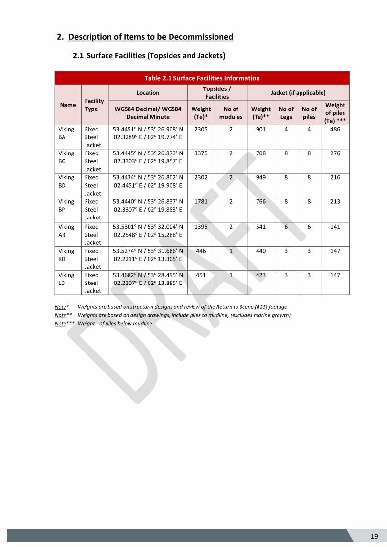
Figure 2.1.1 Photograph of Viking KD
Figure 2.1.2 Photograph of Viking LD
21
5
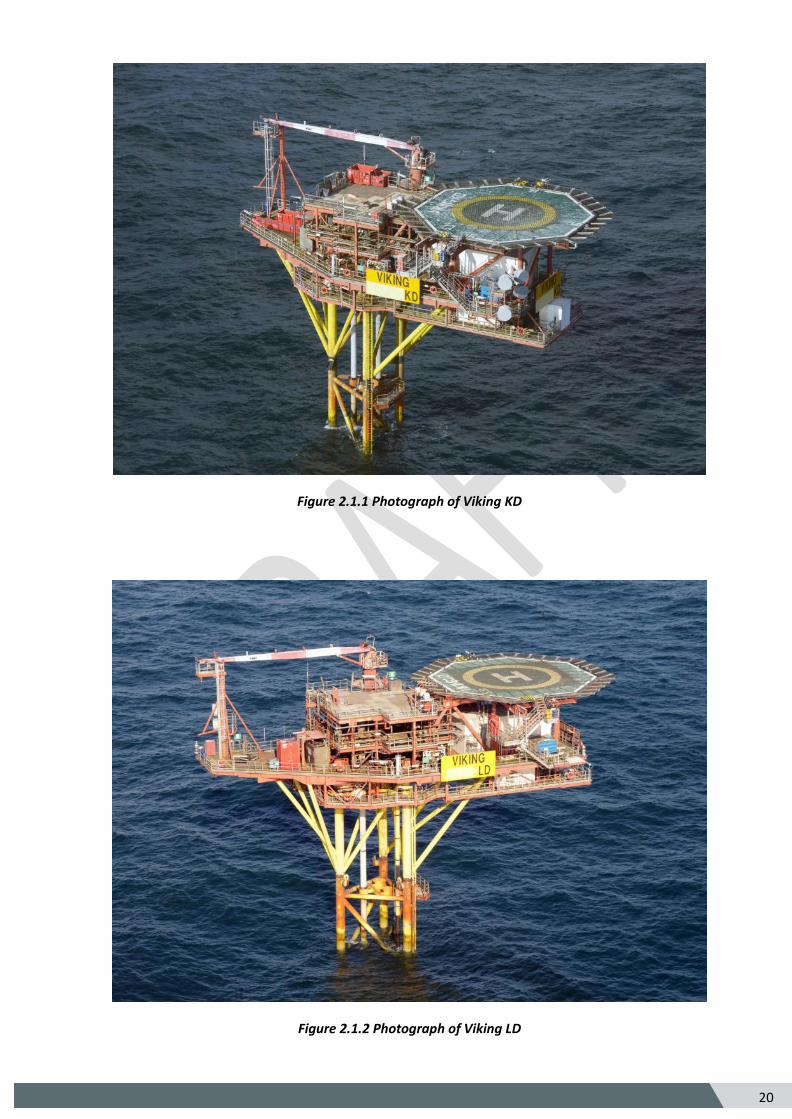
Figure 2.1.3 Photograph of Viking AR
Figure 2.1.4 Photograph of Viking Bravo BA Platform
22
5
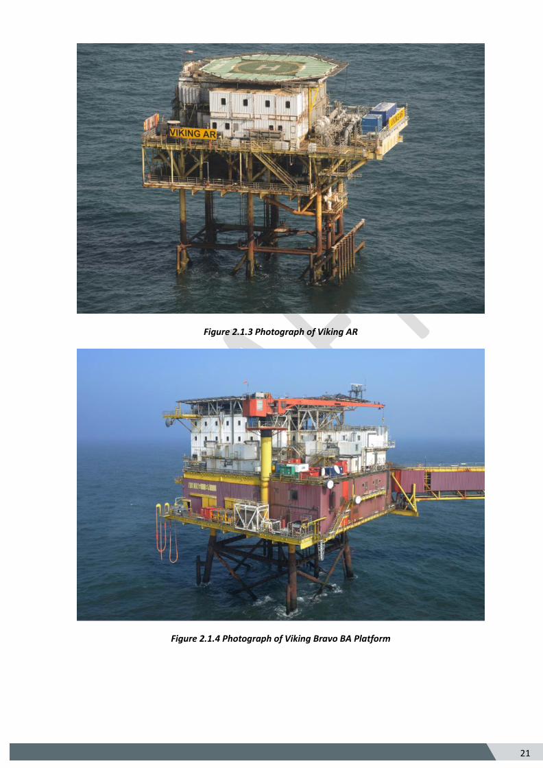
Figure 2.1.5 Photograph of Viking Bravo BC Platform
Figure 2.1.6 Photograph of Viking Bravo BP Platform
23
5
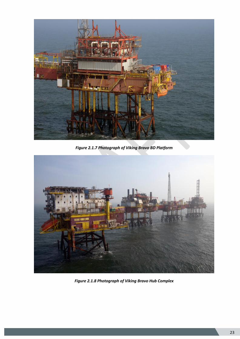
Figure 2.1.7 Photograph of Viking Bravo BD Platform
Figure 2.1.8 Photograph of Viking Bravo Hub Complex
24
5
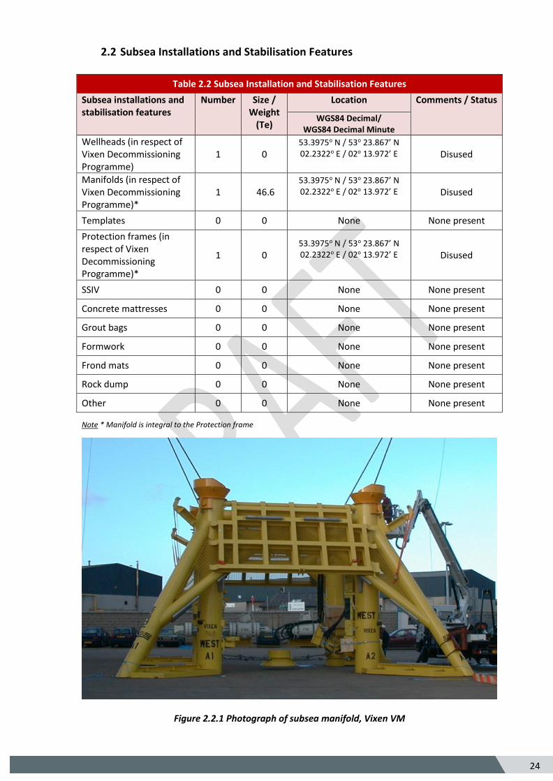
2.2 Subsea Installations and Stabilisation Features
Table 2.2 Subsea Installation and Stabilisation Features
Subsea installations and stabilisation features
Number Size / Weight
(Te)
Location Comments / Status
WGS84 Decimal/ WGS84 Decimal Minute
Wellheads (in respect of Vixen Decommissioning Programme)
1 0 53.3975o N / 53o 23.867’ N 02.2322o E / 02o 13.972’ E
Disused
Manifolds (in respect of Vixen Decommissioning Programme)*
1 46.6 53.3975o N / 53o 23.867’ N 02.2322o E / 02o 13.972’ E
Disused
Templates 0 0 None None present
Protection frames (in respect of Vixen Decommissioning Programme)*
1 0 53.3975o N / 53o 23.867’ N 02.2322o E / 02o 13.972’ E
Disused
SSIV 0 0 None None present
Concrete mattresses 0 0 None None present
Grout bags 0 0 None None present
Formwork 0 0 None None present
Frond mats 0 0 None None present
Rock dump 0 0 None None present
Other 0 0 None None present
Note * Manifold is integral to the Protection frame
Figure 2.2.1 Photograph of subsea manifold, Vixen VM
25 5
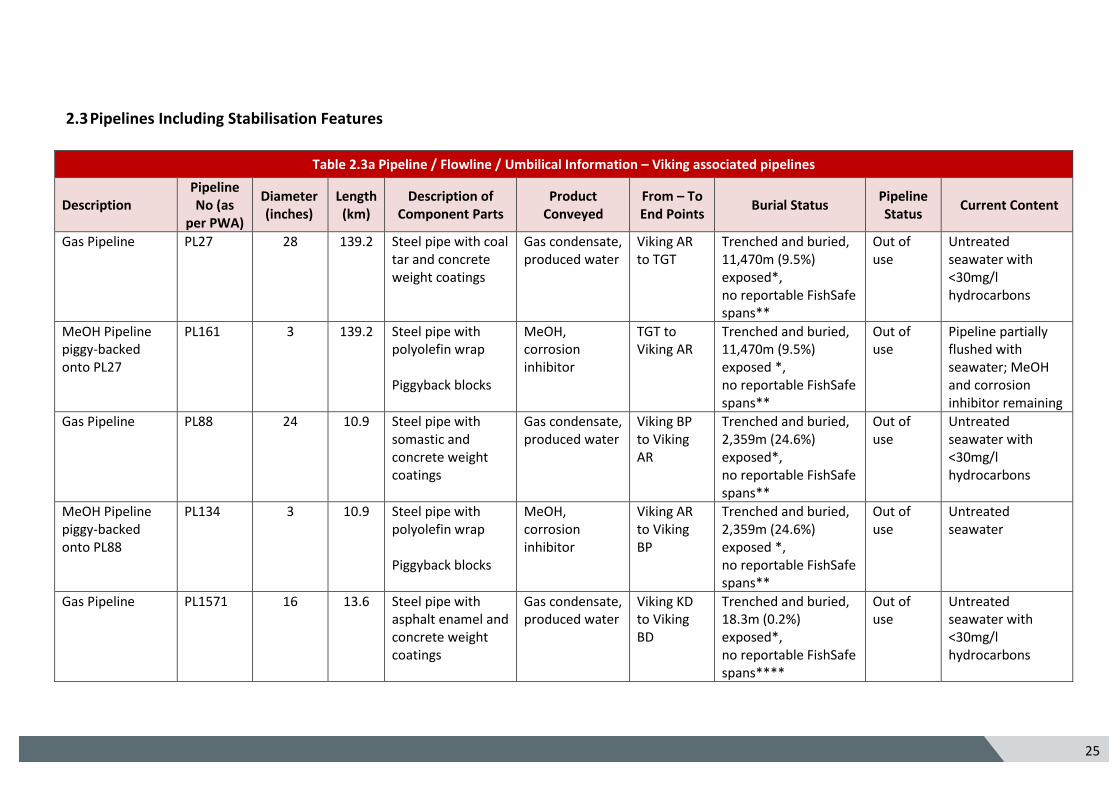
2.3 Pipelines Including Stabilisation Features
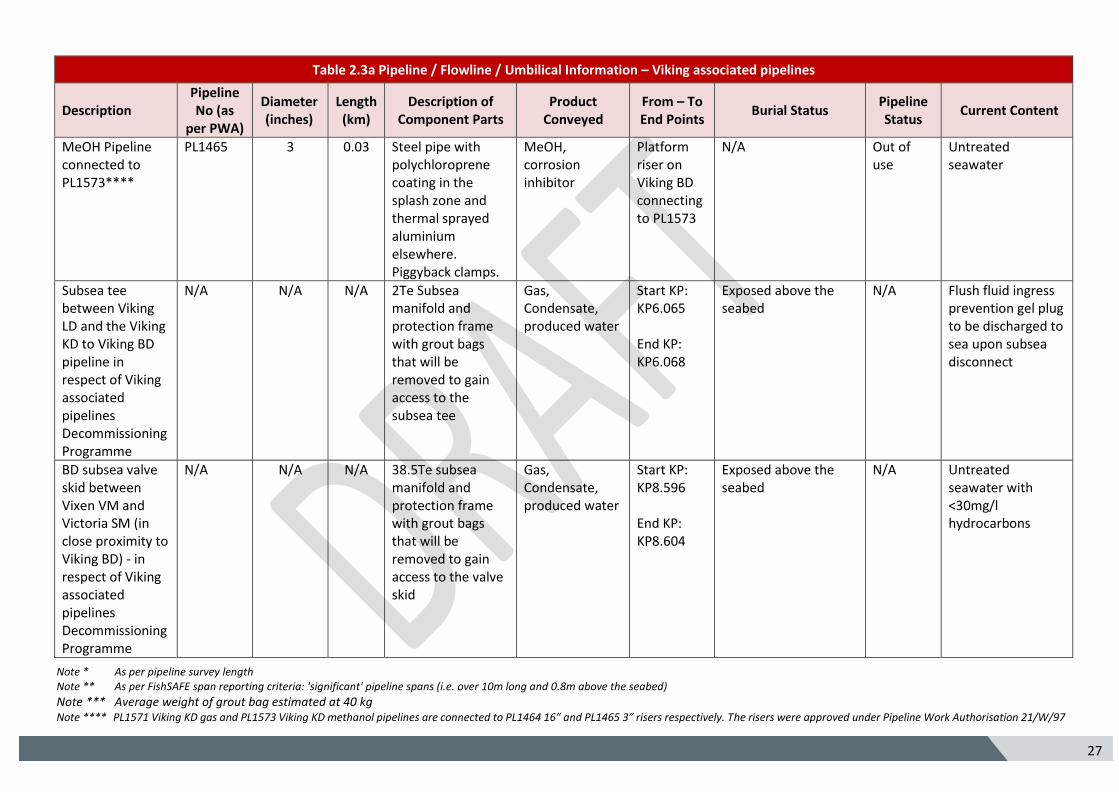
Table 2.3a Pipeline / Flowline / Umbilical Information – Viking associated pipelines
Description Pipeline No (as
per PWA)
Diameter (inches)
Length (km)
Description of Component Parts
Product Conveyed
From – To End Points
Burial Status Pipeline Status
Current Content
Gas Pipeline PL27 28 139.2 Steel pipe with coal tar and concrete weight coatings
Gas condensate, produced water
Viking AR to TGT
Trenched and buried, 11,470m (9.5%) exposed*, no reportable FishSafe spans**
Out of use
Untreated seawater with <30mg/l hydrocarbons
MeOH Pipeline piggy-backed onto PL27
PL161 3 139.2 Steel pipe with polyolefin wrap Piggyback blocks
MeOH, corrosion inhibitor
TGT to Viking AR
Trenched and buried, 11,470m (9.5%) exposed *, no reportable FishSafe spans**
Out of use
Pipeline partially flushed with seawater; MeOH and corrosion inhibitor remaining
Gas Pipeline PL88 24 10.9 Steel pipe with somastic and concrete weight coatings
Gas condensate, produced water
Viking BP to Viking AR
Trenched and buried, 2,359m (24.6%) exposed*, no reportable FishSafe spans**
Out of use
Untreated seawater with <30mg/l hydrocarbons
MeOH Pipeline piggy-backed onto PL88
PL134 3 10.9 Steel pipe with polyolefin wrap Piggyback blocks
MeOH, corrosion inhibitor
Viking AR to Viking BP
Trenched and buried, 2,359m (24.6%) exposed *, no reportable FishSafe spans**
Out of use
Untreated seawater
Gas Pipeline PL1571 16 13.6 Steel pipe with asphalt enamel and concrete weight coatings
Gas condensate, produced water
Viking KD to Viking BD
Trenched and buried, 18.3m (0.2%) exposed*, no reportable FishSafe spans****
Out of use
Untreated seawater with <30mg/l hydrocarbons
26 5
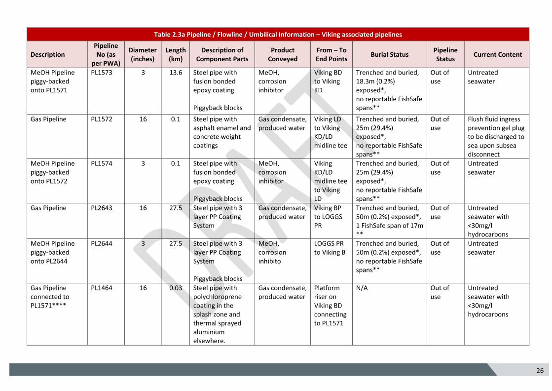
Table 2.3a Pipeline / Flowline / Umbilical Information – Viking associated pipelines
Description Pipeline No (as
per PWA)
Diameter (inches)
Length (km)
Description of Component Parts
Product Conveyed
From – To End Points
Burial Status Pipeline Status
Current Content
MeOH Pipeline piggy-backed onto PL1571
PL1573 3 13.6 Steel pipe with fusion bonded epoxy coating Piggyback blocks
MeOH, corrosion inhibitor
Viking BD to Viking KD
Trenched and buried, 18.3m (0.2%) exposed*, no reportable FishSafe spans**
Out of use
Untreated seawater
Gas Pipeline PL1572 16 0.1 Steel pipe with asphalt enamel and concrete weight coatings
Gas condensate, produced water
Viking LD to Viking KD/LD midline tee
Trenched and buried, 25m (29.4%) exposed*, no reportable FishSafe spans**
Out of use
Flush fluid ingress prevention gel plug to be discharged to sea upon subsea disconnect
MeOH Pipeline piggy-backed onto PL1572
PL1574 3 0.1 Steel pipe with fusion bonded epoxy coating Piggyback blocks
MeOH, corrosion inhibitor
Viking KD/LD midline tee to Viking LD
Trenched and buried, 25m (29.4%) exposed*, no reportable FishSafe spans**
Out of use
Untreated seawater
Gas Pipeline PL2643 16 27.5 Steel pipe with 3 layer PP Coating System
Gas condensate, produced water
Viking BP to LOGGS PR
Trenched and buried, 50m (0.2%) exposed*, 1 FishSafe span of 17m **
Out of use
Untreated seawater with <30mg/l hydrocarbons
MeOH Pipeline piggy-backed onto PL2644
PL2644 3 27.5 Steel pipe with 3 layer PP Coating System Piggyback blocks
MeOH, corrosion inhibito
LOGGS PR to Viking B
Trenched and buried, 50m (0.2%) exposed*, no reportable FishSafe spans**
Out of use
Untreated seawater
Gas Pipeline connected to PL1571****
PL1464
16 0.03 Steel pipe with polychloroprene coating in the splash zone and thermal sprayed aluminium elsewhere.
Gas condensate, produced water
Platform riser on Viking BD connecting to PL1571
N/A Out of use
Untreated seawater with <30mg/l hydrocarbons
27 5
Table 2.3a Pipeline / Flowline / Umbilical Information – Viking associated pipelines
Description Pipeline No (as
per PWA)
Diameter (inches)
Length (km)
Description of Component Parts
Product Conveyed
From – To End Points
Burial Status Pipeline Status
Current Content
MeOH Pipeline connected to PL1573****
PL1465
3 0.03 Steel pipe with polychloroprene coating in the splash zone and thermal sprayed aluminium elsewhere. Piggyback clamps.
MeOH, corrosion inhibitor
Platform riser on Viking BD connecting to PL1573
N/A Out of use
Untreated seawater
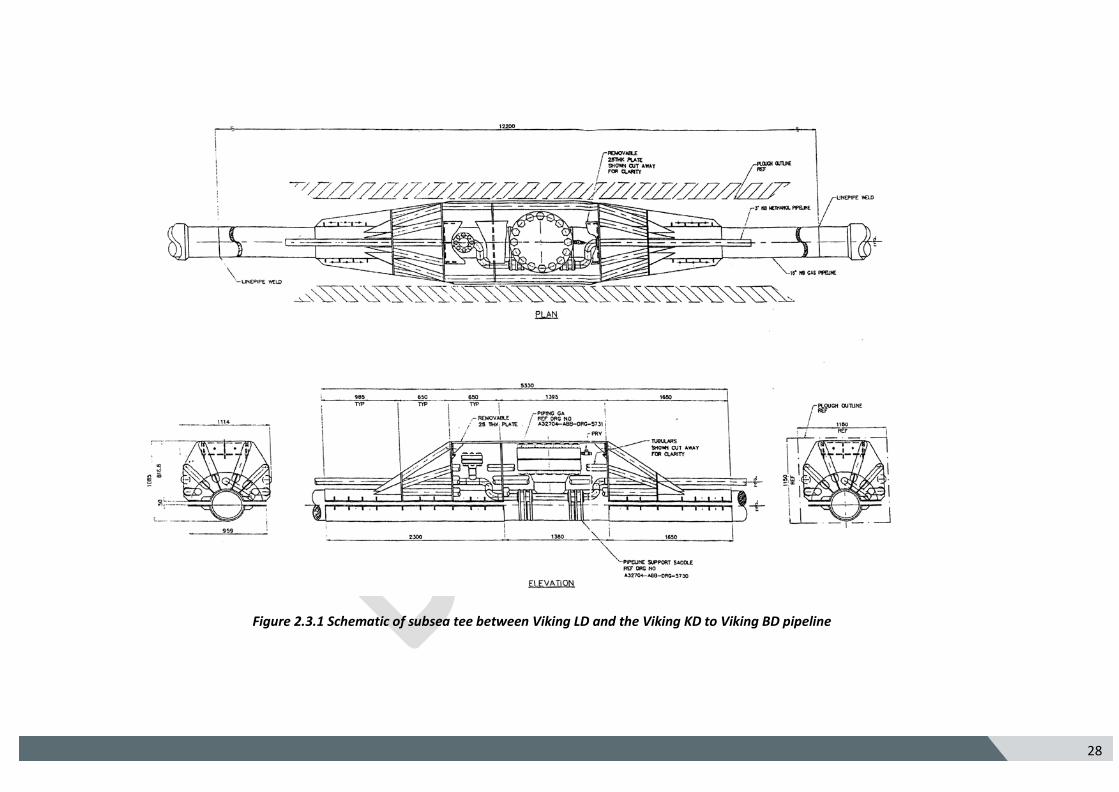
Subsea tee between Viking LD and the Viking KD to Viking BD pipeline in respect of Viking associated pipelines Decommissioning Programme
N/A N/A N/A 2Te Subsea manifold and protection frame with grout bags that will be removed to gain access to the subsea tee
Gas, Condensate, produced water
Start KP: KP6.065 End KP: KP6.068
Exposed above the seabed
N/A Flush fluid ingress prevention gel plug to be discharged to sea upon subsea disconnect
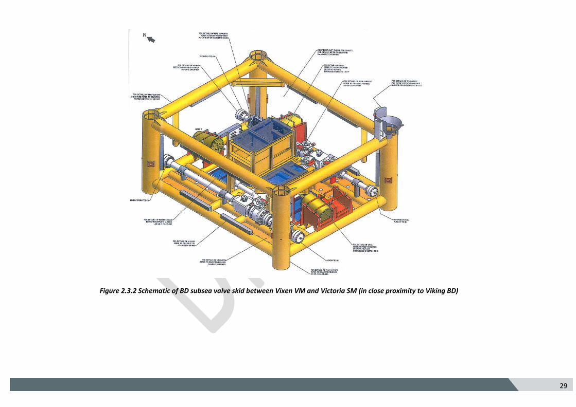
BD subsea valve skid between Vixen VM and Victoria SM (in close proximity to Viking BD) - in respect of Viking associated pipelines Decommissioning Programme
N/A N/A N/A 38.5Te subsea manifold and protection frame with grout bags that will be removed to gain access to the valve skid
Gas, Condensate, produced water
Start KP: KP8.596 End KP: KP8.604
Exposed above the seabed
N/A Untreated seawater with <30mg/l hydrocarbons
Note * As per pipeline survey length Note ** As per FishSAFE span reporting criteria: 'significant' pipeline spans (i.e. over 10m long and 0.8m above the seabed)
Note *** Average weight of grout bag estimated at 40 kg Note **** PL1571 Viking KD gas and PL1573 Viking KD methanol pipelines are connected to PL1464 16” and PL1465 3” risers respectively. The risers were approved under Pipeline Work Authorisation 21/W/97
28 5
Figure 2.3.1 Schematic of subsea tee between Viking LD and the Viking KD to Viking BD pipeline
29 5
Figure 2.3.2 Schematic of BD subsea valve skid between Vixen VM and Victoria SM (in close proximity to Viking BD)
30 5
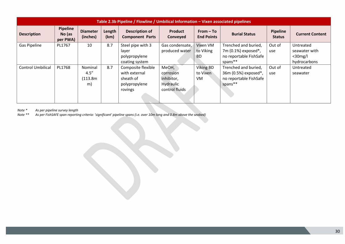
Table 2.3b Pipeline / Flowline / Umbilical Information – Vixen associated pipelines
Description Pipeline No (as
per PWA)
Diameter (inches)
Length (km)
Description of Component Parts
Product Conveyed
From – To End Points
Burial Status Pipeline Status
Current Content
Gas Pipeline PL1767 10 8.7 Steel pipe with 3 layer polypropylene coating system
Gas condensate, produced water
Vixen VM to Viking BD
Trenched and buried, 7m (0.1%) exposed*, no reportable FishSafe spans**
Out of use
Untreated seawater with <30mg/l hydrocarbons
Control Umbilical
PL1768 Nominal 4.5”
(113.8mm)
8.7 Composite flexible with external sheath of polypropylene rovings
MeOH, corrosion inhibitor, Hydraulic control fluids
Viking BD to Vixen VM
Trenched and buried, 36m (0.5%) exposed*, no reportable FishSafe spans**
Out of use
Untreated seawater
Note * As per pipeline survey length Note ** As per FishSAFE span reporting criteria: 'significant' pipeline spans (i.e. over 10m long and 0.8m above the seabed)
31 5
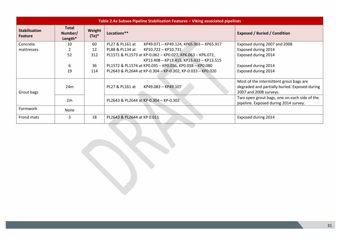
Table 2.4a Subsea Pipeline Stabilisation Features – Viking associated pipelines
Stabilisation Feature
Total Number/ Length*
Weight (Te)*
Locations** Exposed / Buried / Condition
Concrete mattresses
10 2
52
6 19
60 12
312
36 114
PL27 & PL161 at KP49.071 – KP49.124, KP65.903 – KP65.917 PL88 & PL134 at KP10.722 – KP10.731 PL1571 & PL1573 at KP-0.062 – KP0.027, KP6.063 – KP6.072, KP13.408 – KP13.415, KP13.433 – KP13.515 PL1572 & PL1574 at KP0.035 – KP0.036, KP0.058 – KP0.080 PL2643 & PL2644 at KP-0.304 – KP-0.302, KP-0.033 – KP0.020
Exposed during 2007 and 2008 Exposed during 2014 Exposed during 2014 Exposed during 2014 Exposed during 2014
Grout bags 24m
PL27 & PL161 at KP49.083 – KP49.107
Most of the intermittent grout bags are degraded and partially buried. Exposed during 2007 and 2008 surveys.
2m PL2643 & PL2644 at KP-0.304 – KP-0.302 Two open grout bags, one on each side of the pipeline. Exposed during 2014 survey.
Formwork None
Frond mats 3 18 PL2643 & PL2644 at KP 0.011 Exposed during 2014
32 5
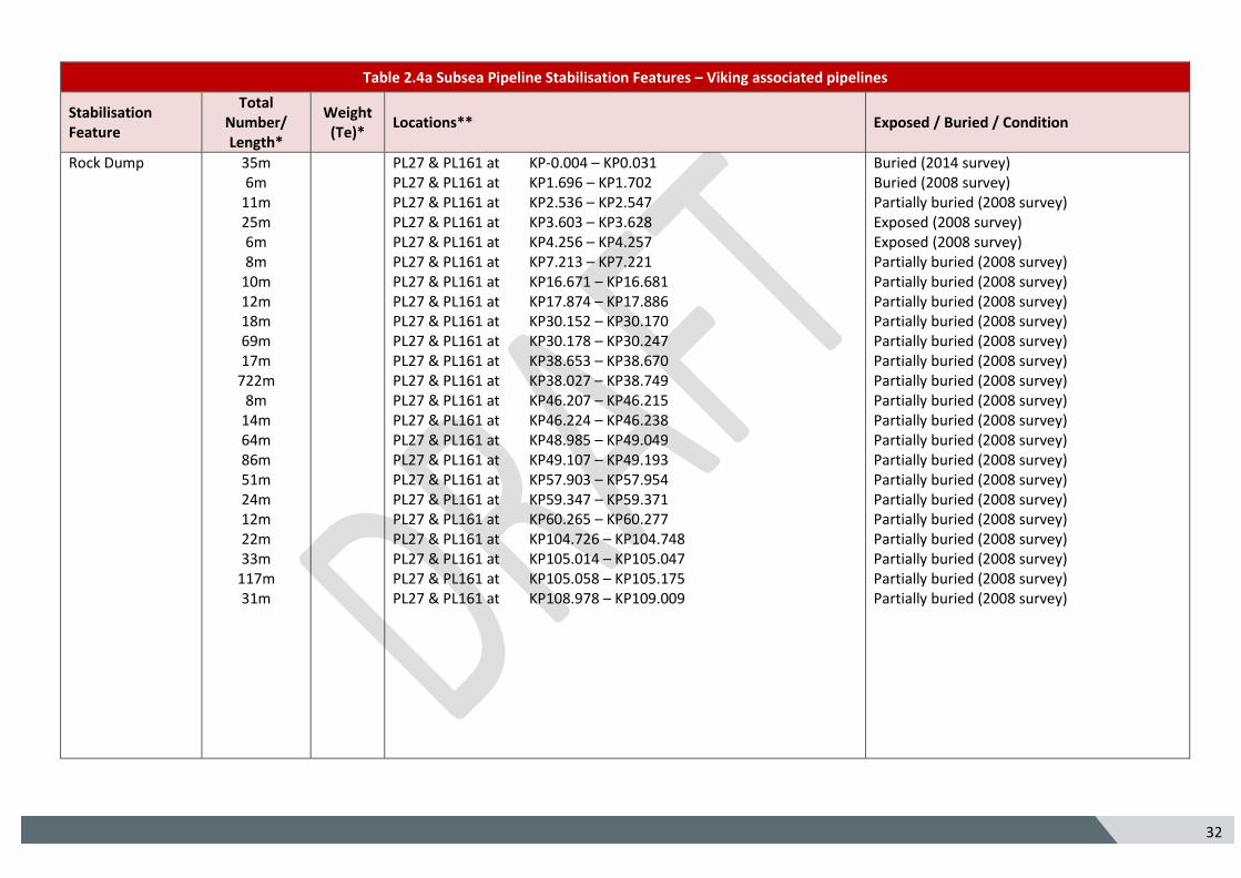
Table 2.4a Subsea Pipeline Stabilisation Features – Viking associated pipelines
Stabilisation Feature
Total Number/ Length*
Weight (Te)*
Locations** Exposed / Buried / Condition
Rock Dump 35m 6m
11m 25m 6m 8m
10m 12m 18m 69m 17m
722m 8m
14m 64m 86m 51m 24m 12m 22m 33m
117m 31m
PL27 & PL161 at KP-0.004 – KP0.031 PL27 & PL161 at KP1.696 – KP1.702 PL27 & PL161 at KP2.536 – KP2.547 PL27 & PL161 at KP3.603 – KP3.628 PL27 & PL161 at KP4.256 – KP4.257 PL27 & PL161 at KP7.213 – KP7.221 PL27 & PL161 at KP16.671 – KP16.681 PL27 & PL161 at KP17.874 – KP17.886 PL27 & PL161 at KP30.152 – KP30.170 PL27 & PL161 at KP30.178 – KP30.247 PL27 & PL161 at KP38.653 – KP38.670 PL27 & PL161 at KP38.027 – KP38.749 PL27 & PL161 at KP46.207 – KP46.215 PL27 & PL161 at KP46.224 – KP46.238 PL27 & PL161 at KP48.985 – KP49.049 PL27 & PL161 at KP49.107 – KP49.193 PL27 & PL161 at KP57.903 – KP57.954 PL27 & PL161 at KP59.347 – KP59.371 PL27 & PL161 at KP60.265 – KP60.277 PL27 & PL161 at KP104.726 – KP104.748 PL27 & PL161 at KP105.014 – KP105.047 PL27 & PL161 at KP105.058 – KP105.175 PL27 & PL161 at KP108.978 – KP109.009
Buried (2014 survey) Buried (2008 survey) Partially buried (2008 survey) Exposed (2008 survey) Exposed (2008 survey) Partially buried (2008 survey) Partially buried (2008 survey) Partially buried (2008 survey) Partially buried (2008 survey) Partially buried (2008 survey) Partially buried (2008 survey) Partially buried (2008 survey) Partially buried (2008 survey) Partially buried (2008 survey) Partially buried (2008 survey) Partially buried (2008 survey) Partially buried (2008 survey) Partially buried (2008 survey) Partially buried (2008 survey) Partially buried (2008 survey) Partially buried (2008 survey) Partially buried (2008 survey) Partially buried (2008 survey)
33 5
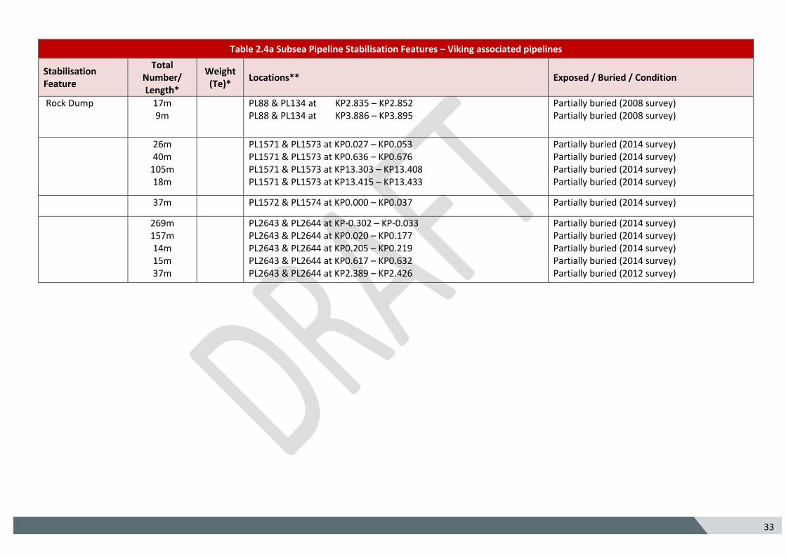
Table 2.4a Subsea Pipeline Stabilisation Features – Viking associated pipelines
Stabilisation Feature
Total Number/ Length*
Weight (Te)*
Locations** Exposed / Buried / Condition
Rock Dump 17m 9m
PL88 & PL134 at KP2.835 – KP2.852 PL88 & PL134 at KP3.886 – KP3.895
Partially buried (2008 survey) Partially buried (2008 survey)
26m 40m
105m 18m
PL1571 & PL1573 at KP0.027 – KP0.053 PL1571 & PL1573 at KP0.636 – KP0.676 PL1571 & PL1573 at KP13.303 – KP13.408 PL1571 & PL1573 at KP13.415 – KP13.433
Partially buried (2014 survey) Partially buried (2014 survey) Partially buried (2014 survey) Partially buried (2014 survey)
37m PL1572 & PL1574 at KP0.000 – KP0.037 Partially buried (2014 survey)
269m 157m 14m 15m 37m
PL2643 & PL2644 at KP-0.302 – KP-0.033 PL2643 & PL2644 at KP0.020 – KP0.177 PL2643 & PL2644 at KP0.205 – KP0.219 PL2643 & PL2644 at KP0.617 – KP0.632 PL2643 & PL2644 at KP2.389 – KP2.426
Partially buried (2014 survey) Partially buried (2014 survey) Partially buried (2014 survey) Partially buried (2014 survey) Partially buried (2012 survey)
34 5
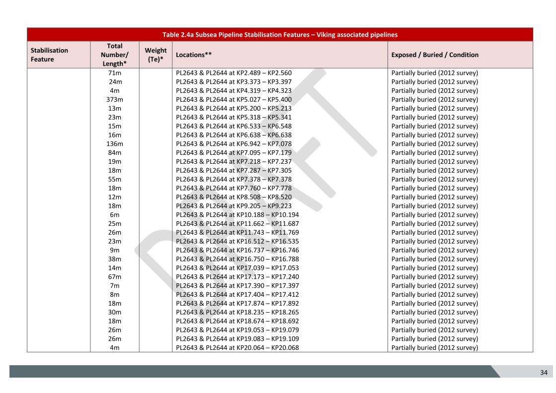
Table 2.4a Subsea Pipeline Stabilisation Features – Viking associated pipelines
Stabilisation Feature
Total Number/ Length*
Weight (Te)*
Locations** Exposed / Buried / Condition
71m 24m 4m
373m 13m 23m 15m 16m
136m 84m 19m 18m 55m 18m 12m 18m 6m
25m 26m 23m 9m
38m 14m 67m 7m 8m
18m 30m 18m 26m 26m 4m
PL2643 & PL2644 at KP2.489 – KP2.560 PL2643 & PL2644 at KP3.373 – KP3.397 PL2643 & PL2644 at KP4.319 – KP4.323 PL2643 & PL2644 at KP5.027 – KP5.400 PL2643 & PL2644 at KP5.200 – KP5.213 PL2643 & PL2644 at KP5.318 – KP5.341 PL2643 & PL2644 at KP6.533 – KP6.548 PL2643 & PL2644 at KP6.638 – KP6.638 PL2643 & PL2644 at KP6.942 – KP7.078 PL2643 & PL2644 at KP7.095 – KP7.179 PL2643 & PL2644 at KP7.218 – KP7.237 PL2643 & PL2644 at KP7.287 – KP7.305 PL2643 & PL2644 at KP7.378 – KP7.378 PL2643 & PL2644 at KP7.760 – KP7.778 PL2643 & PL2644 at KP8.508 – KP8.520 PL2643 & PL2644 at KP9.205 – KP9.223 PL2643 & PL2644 at KP10.188 – KP10.194 PL2643 & PL2644 at KP11.662 – KP11.687 PL2643 & PL2644 at KP11.743 – KP11.769 PL2643 & PL2644 at KP16.512 – KP16.535 PL2643 & PL2644 at KP16.737 – KP16.746 PL2643 & PL2644 at KP16.750 – KP16.788 PL2643 & PL2644 at KP17.039 – KP17.053 PL2643 & PL2644 at KP17.173 – KP17.240 PL2643 & PL2644 at KP17.390 – KP17.397 PL2643 & PL2644 at KP17.404 – KP17.412 PL2643 & PL2644 at KP17.874 – KP17.892 PL2643 & PL2644 at KP18.235 – KP18.265 PL2643 & PL2644 at KP18.674 – KP18.692 PL2643 & PL2644 at KP19.053 – KP19.079 PL2643 & PL2644 at KP19.083 – KP19.109 PL2643 & PL2644 at KP20.064 – KP20.068
Partially buried (2012 survey) Partially buried (2012 survey) Partially buried (2012 survey) Partially buried (2012 survey) Partially buried (2012 survey) Partially buried (2012 survey) Partially buried (2012 survey) Partially buried (2012 survey) Partially buried (2012 survey) Partially buried (2012 survey) Partially buried (2012 survey) Partially buried (2012 survey) Partially buried (2012 survey) Partially buried (2012 survey) Partially buried (2012 survey) Partially buried (2012 survey) Partially buried (2012 survey) Partially buried (2012 survey) Partially buried (2012 survey) Partially buried (2012 survey) Partially buried (2012 survey) Partially buried (2012 survey) Partially buried (2012 survey) Partially buried (2012 survey) Partially buried (2012 survey) Partially buried (2012 survey) Partially buried (2012 survey) Partially buried (2012 survey) Partially buried (2012 survey) Partially buried (2012 survey) Partially buried (2012 survey) Partially buried (2012 survey)
35 5
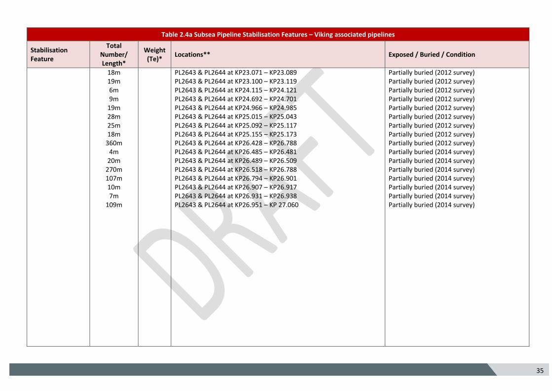
Table 2.4a Subsea Pipeline Stabilisation Features – Viking associated pipelines
Stabilisation Feature
Total Number/ Length*
Weight (Te)*
Locations** Exposed / Buried / Condition
18m 19m 6m 9m
19m 28m 25m 18m
360m 4m
20m 270m 107m 10m 7m
109m
PL2643 & PL2644 at KP23.071 – KP23.089 PL2643 & PL2644 at KP23.100 – KP23.119 PL2643 & PL2644 at KP24.115 – KP24.121 PL2643 & PL2644 at KP24.692 – KP24.701 PL2643 & PL2644 at KP24.966 – KP24.985 PL2643 & PL2644 at KP25.015 – KP25.043 PL2643 & PL2644 at KP25.092 – KP25.117 PL2643 & PL2644 at KP25.155 – KP25.173 PL2643 & PL2644 at KP26.428 – KP26.788 PL2643 & PL2644 at KP26.485 – KP26.481 PL2643 & PL2644 at KP26.489 – KP26.509 PL2643 & PL2644 at KP26.518 – KP26.788 PL2643 & PL2644 at KP26.794 – KP26.901 PL2643 & PL2644 at KP26.907 – KP26.917 PL2643 & PL2644 at KP26.931 – KP26.938 PL2643 & PL2644 at KP26.951 – KP 27.060
Partially buried (2012 survey) Partially buried (2012 survey) Partially buried (2012 survey) Partially buried (2012 survey) Partially buried (2012 survey) Partially buried (2012 survey) Partially buried (2012 survey) Partially buried (2012 survey) Partially buried (2012 survey) Partially buried (2014 survey) Partially buried (2014 survey) Partially buried (2014 survey) Partially buried (2014 survey) Partially buried (2014 survey) Partially buried (2014 survey) Partially buried (2014 survey)
36 5
Table 2.4a Subsea Pipeline Stabilisation Features – Viking associated pipelines
Stabilisation Feature
Total Number/ Length*
Weight (Te)*
Locations** Exposed / Buried / Condition
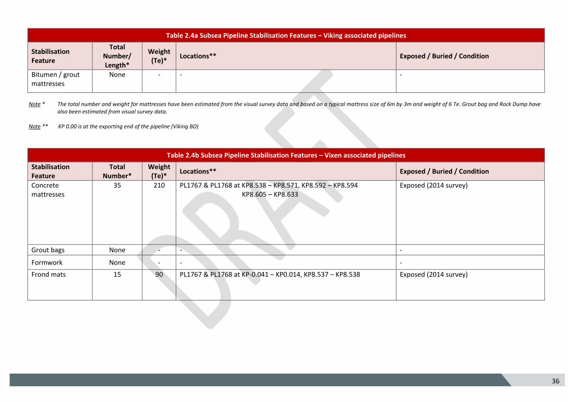
Bitumen / grout mattresses
None - - -
Note * The total number and weight for mattresses have been estimated from the visual survey data and based on a typical mattress size of 6m by 3m and weight of 6 Te. Grout bag and Rock Dump have
also been estimated from visual survey data. Note ** KP 0.00 is at the exporting end of the pipeline (Viking BD)
Table 2.4b Subsea Pipeline Stabilisation Features – Vixen associated pipelines
Stabilisation Feature
Total Number*
Weight (Te)*
Locations** Exposed / Buried / Condition
Concrete mattresses
35 210 PL1767 & PL1768 at KP8.538 – KP8.571, KP8.592 – KP8.594 KP8.605 – KP8.633
Exposed (2014 survey)
Grout bags None - - -
Formwork None - - -
Frond mats 15 90 PL1767 & PL1768 at KP-0.041 – KP0.014, KP8.537 – KP8.538 Exposed (2014 survey)
37 5
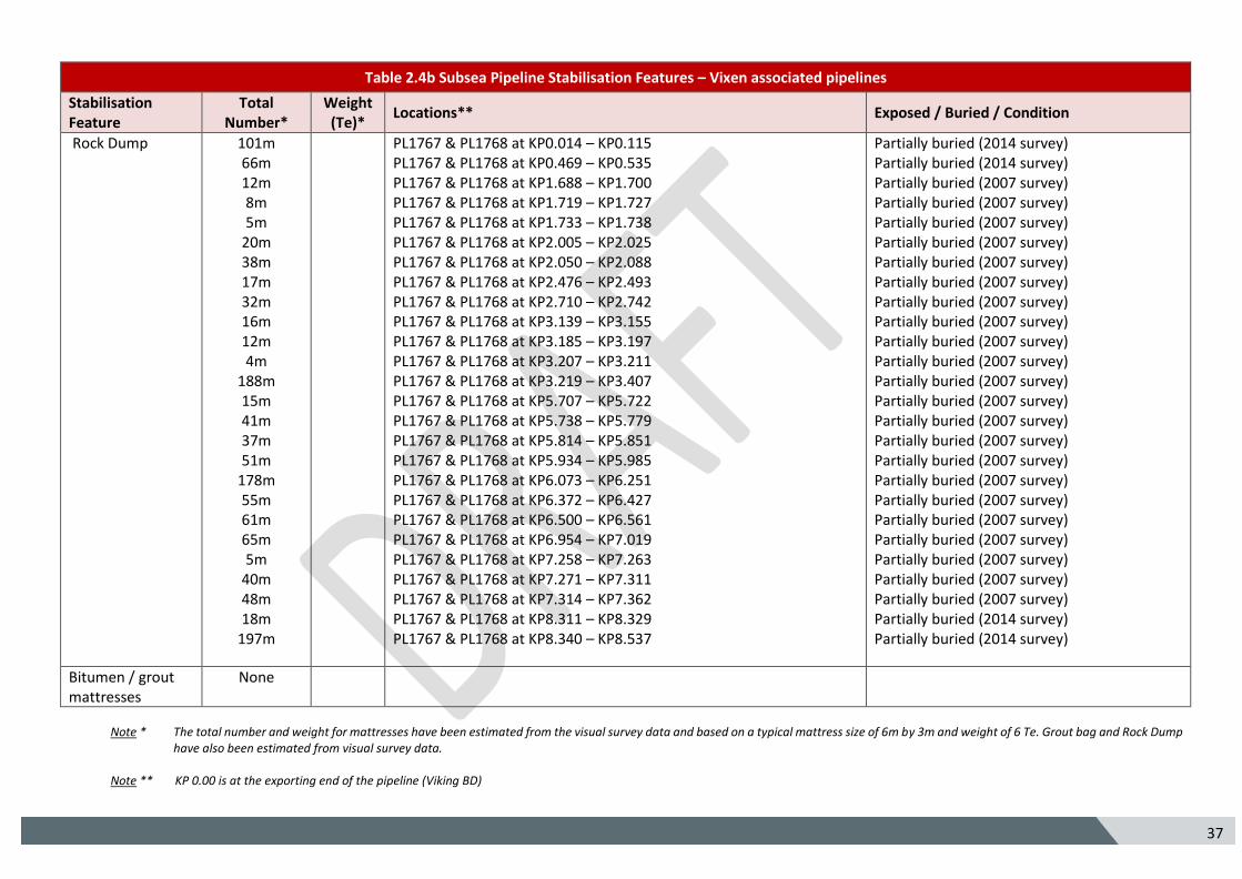
Table 2.4b Subsea Pipeline Stabilisation Features – Vixen associated pipelines
Stabilisation Feature
Total Number*
Weight (Te)*
Locations** Exposed / Buried / Condition
Rock Dump 101m 66m 12m 8m 5m
20m 38m 17m 32m 16m 12m 4m
188m 15m 41m 37m 51m
178m 55m 61m 65m 5m
40m 48m 18m
197m
PL1767 & PL1768 at KP0.014 – KP0.115 PL1767 & PL1768 at KP0.469 – KP0.535 PL1767 & PL1768 at KP1.688 – KP1.700 PL1767 & PL1768 at KP1.719 – KP1.727 PL1767 & PL1768 at KP1.733 – KP1.738 PL1767 & PL1768 at KP2.005 – KP2.025 PL1767 & PL1768 at KP2.050 – KP2.088 PL1767 & PL1768 at KP2.476 – KP2.493 PL1767 & PL1768 at KP2.710 – KP2.742 PL1767 & PL1768 at KP3.139 – KP3.155 PL1767 & PL1768 at KP3.185 – KP3.197 PL1767 & PL1768 at KP3.207 – KP3.211 PL1767 & PL1768 at KP3.219 – KP3.407 PL1767 & PL1768 at KP5.707 – KP5.722 PL1767 & PL1768 at KP5.738 – KP5.779 PL1767 & PL1768 at KP5.814 – KP5.851 PL1767 & PL1768 at KP5.934 – KP5.985 PL1767 & PL1768 at KP6.073 – KP6.251 PL1767 & PL1768 at KP6.372 – KP6.427 PL1767 & PL1768 at KP6.500 – KP6.561 PL1767 & PL1768 at KP6.954 – KP7.019 PL1767 & PL1768 at KP7.258 – KP7.263 PL1767 & PL1768 at KP7.271 – KP7.311 PL1767 & PL1768 at KP7.314 – KP7.362 PL1767 & PL1768 at KP8.311 – KP8.329 PL1767 & PL1768 at KP8.340 – KP8.537
Partially buried (2014 survey) Partially buried (2014 survey) Partially buried (2007 survey) Partially buried (2007 survey) Partially buried (2007 survey) Partially buried (2007 survey) Partially buried (2007 survey) Partially buried (2007 survey) Partially buried (2007 survey) Partially buried (2007 survey) Partially buried (2007 survey) Partially buried (2007 survey) Partially buried (2007 survey) Partially buried (2007 survey) Partially buried (2007 survey) Partially buried (2007 survey) Partially buried (2007 survey) Partially buried (2007 survey) Partially buried (2007 survey) Partially buried (2007 survey) Partially buried (2007 survey) Partially buried (2007 survey) Partially buried (2007 survey) Partially buried (2007 survey) Partially buried (2014 survey) Partially buried (2014 survey)
Bitumen / grout mattresses
None
Note * The total number and weight for mattresses have been estimated from the visual survey data and based on a typical mattress size of 6m by 3m and weight of 6 Te. Grout bag and Rock Dump
have also been estimated from visual survey data. Note ** KP 0.00 is at the exporting end of the pipeline (Viking BD)
38 5
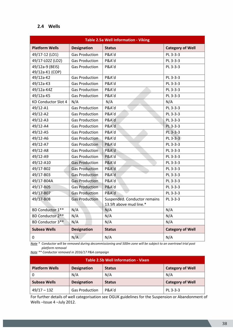
2.4 Wells
Table 2.5a Well Information - Viking
Platform Wells Designation Status Category of Well
49/17-12 (LD1) Gas Production P&A’d PL 3-3-3
49/17-L02Z (LD2) Gas Production P&A’d PL 3-3-3
49/12a-9 (BEIS) 49/12a-K1 (COP)
Gas Production P&A’d PL 3-3-3
49/12a-K2 Gas Production P&A’d PL 3-3-3
49/12a-K3 Gas Production P&A’d PL 3-3-3
49/12a-K4Z Gas Production P&A’d PL 3-3-3
49/12a-K5 Gas Production P&A’d PL 3-3-3
KD Conductor Slot 4 N/A N/A N/A
49/12-A1 Gas Production P&A’d PL 3-3-3
49/12-A2 Gas Production P&A’d PL 3-3-3
49/12-A3 Gas Production P&A’d PL 3-3-3
49/12-A4 Gas Production P&A’d PL 3-3-3
49/12-A5 Gas Production P&A’d PL 3-3-3
49/12-A6 Gas Production P&A’d PL 3-3-3
49/12-A7 Gas Production P&A’d PL 3-3-3
49/12-A8 Gas Production P&A’d PL 3-3-3
49/12-A9 Gas Production P&A’d PL 3-3-3
49/12-A10 Gas Production P&A’d PL 3-3-3
49/17-B02 Gas Production P&A’d PL 3-3-3
49/17-B03 Gas Production P&A’d PL 3-3-3
49/17-B04A Gas Production P&A’d PL 3-3-3
49/17-B05 Gas Production P&A’d PL 3-3-3
49/17-B07 Gas Production P&A’d PL 3-3-3
49/17-B08 Gas Production Suspended. Conductor remains 13.5ft above mud line.*
PL 3-3-3
BD Conductor 1** N/A N/A N/A
BD Conductor 2** N/A N/A N/A
BD Conductor 3** N/A N/A N/A
Subsea Wells Designation Status Category of Well
0 N/A N/A N/A
Note * Conductor will be removed during decommissioning and 500m zone will be subject to an overtrawl trial post platform removal
Note ** Conductor removed in 2016/17 P&A campaign
Table 2.5b Well Information - Vixen
Platform Wells Designation Status Category of Well
0 N/A N/A N/A
Subsea Wells Designation Status Category of Well
49/17 – 13Z Gas Production P&A’d PL 3-3-3
For further details of well categorisation see OGUK guidelines for the Suspension or Abandonment of Wells –Issue 4 –July 2012.
39 5
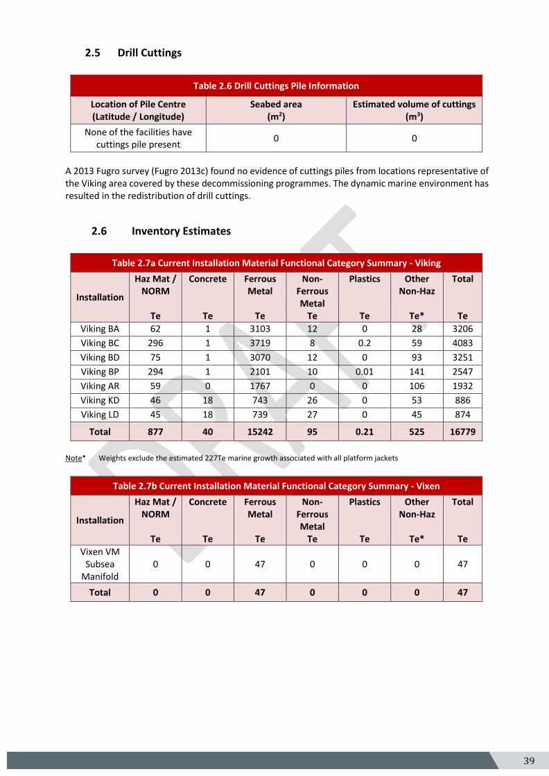
2.5 Drill Cuttings
Table 2.6 Drill Cuttings Pile Information
Location of Pile Centre (Latitude / Longitude)
Seabed area (m2)
Estimated volume of cuttings (m3)
None of the facilities have cuttings pile present
0 0
A 2013 Fugro survey (Fugro 2013c) found no evidence of cuttings piles from locations representative of the Viking area covered by these decommissioning programmes. The dynamic marine environment has resulted in the redistribution of drill cuttings.
2.6 Inventory Estimates
Table 2.7a Current Installation Material Functional Category Summary - Viking
Installation
Haz Mat / NORM
Te
Concrete
Te
Ferrous Metal
Te
Non-Ferrous Metal
Te
Plastics
Te
Other Non-Haz
Te*
Total
Te
Viking BA 62 1 3103 12 0 28 3206
Viking BC 296 1 3719 8 0.2 59 4083
Viking BD 75 1 3070 12 0 93 3251
Viking BP 294 1 2101 10 0.01 141 2547
Viking AR 59 0 1767 0 0 106 1932
Viking KD 46 18 743 26 0 53 886
Viking LD 45 18 739 27 0 45 874
Total 877 40 15242 95 0.21 525 16779
Note* Weights exclude the estimated 227Te marine growth associated with all platform jackets
Table 2.7b Current Installation Material Functional Category Summary - Vixen
Installation
Haz Mat / NORM
Te
Concrete
Te
Ferrous Metal
Te
Non-Ferrous Metal
Te
Plastics
Te
Other Non-Haz
Te*
Total
Te
Vixen VM Subsea
Manifold 0 0 47 0 0 0 47
Total 0 0 47 0 0 0 47
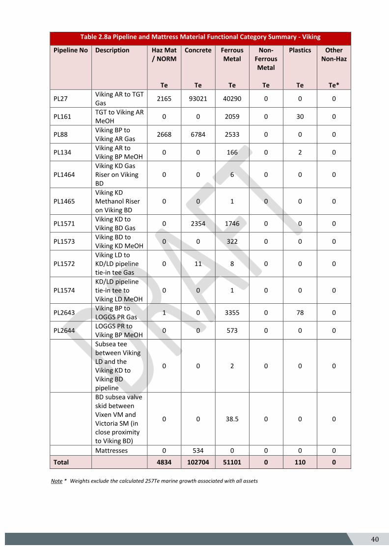
40 5
Table 2.8a Pipeline and Mattress Material Functional Category Summary - Viking
Pipeline No
Description Haz Mat / NORM
Te
Concrete
Te
Ferrous Metal
Te
Non-Ferrous Metal
Te
Plastics
Te
Other Non-Haz
Te*
PL27 Viking AR to TGT Gas
2165 93021 40290 0 0 0
PL161 TGT to Viking AR MeOH
0 0 2059 0 30 0
PL88 Viking BP to Viking AR Gas
2668 6784 2533 0 0 0
PL134 Viking AR to Viking BP MeOH
0 0 166 0 2 0
PL1464 Viking KD Gas Riser on Viking BD
0 0 6 0 0 0
PL1465 Viking KD Methanol Riser on Viking BD
0 0 1 0 0 0
PL1571 Viking KD to Viking BD Gas
0 2354 1746 0 0 0
PL1573 Viking BD to Viking KD MeOH
0 0 322 0 0 0
PL1572 Viking LD to KD/LD pipeline tie-in tee Gas
0 11 8 0 0 0
PL1574 KD/LD pipeline tie-in tee to Viking LD MeOH
0 0 1 0 0 0
PL2643 Viking BP to LOGGS PR Gas
1 0 3355 0 78 0
PL2644 LOGGS PR to Viking BP MeOH
0 0 573 0 0 0
Subsea tee between Viking LD and the Viking KD to Viking BD pipeline
0 0 2 0 0 0
BD subsea valve skid between Vixen VM and Victoria SM (in close proximity to Viking BD)
0 0 38.5 0 0 0
Mattresses 0 534 0 0 0 0
Total 4834 102704 51101 0 110 0
Note * Weights exclude the calculated 257Te marine growth associated with all assets

41 5
Table 2.8b Pipeline and Mattress Material Functional Category Summary - Vixen
Pipeline No
Description Haz Mat / NORM
Te
Concrete
Te
Ferrous Metal
Te
Non-Ferrous Metal
Te
Plastics
Te
Other Non-Haz
Te*
PL1767 Vixen VM to Viking BD Gas
1 0 857 0 15 0
PL1768 Viking BD to Vixen VM Umbilical
0 0 115 0 44 0
Mattresses 0 300 0 0 0 0
Total 1 300 972 0 59 0
42 5
3. Removal and Disposal Methods In line with the waste hierarchy, the re-use of an installation (or parts thereof) is first in the order of preferred decommissioning options considered. Options considered for re-use of the Viking Hub and Satellites and Vixen Manifold were:
• Further Hydrocarbon production from development local to the satellites
• Relocation elsewhere to produce hydrocarbons
• Sale for reuse to others
No economic hydrocarbon developments local to any of the Viking Hub and Satellites were identified. The Viking Hub and Satellites are past their design life, require refurbishment and contain obsolete control systems and components. Their re-use would be uneconomic. The selected option for the Viking Hub and Satellites is to remove, dismantle and dispose of them, ensuring a high level of material recycling.
3.1 Topsides
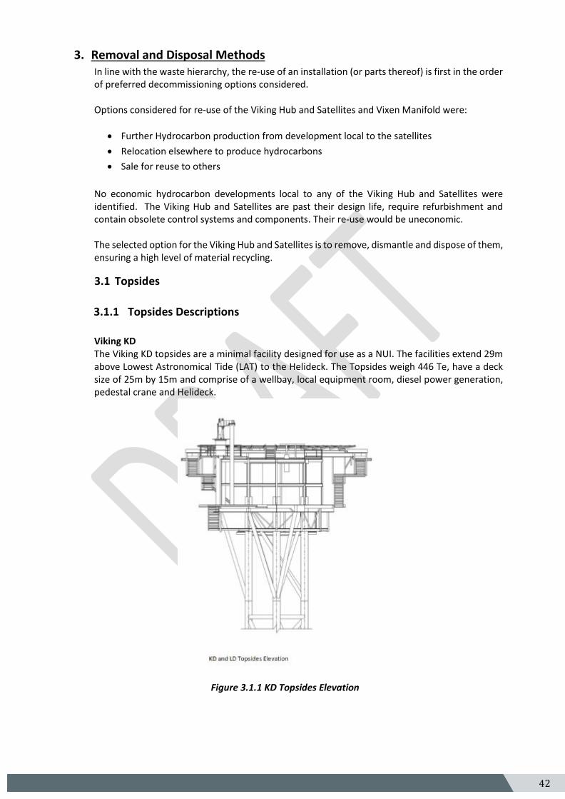
3.1.1 Topsides Descriptions
Viking KD The Viking KD topsides are a minimal facility designed for use as a NUI. The facilities extend 29m above Lowest Astronomical Tide (LAT) to the Helideck. The Topsides weigh 446 Te, have a deck size of 25m by 15m and comprise of a wellbay, local equipment room, diesel power generation, pedestal crane and Helideck.
Figure 3.1.1 KD Topsides Elevation
43 5
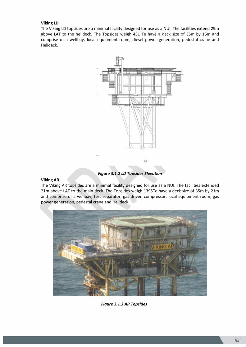
Viking LD The Viking LD topsides are a minimal facility designed for use as a NUI. The facilities extend 29m above LAT to the helideck. The Topsides weigh 451 Te have a deck size of 35m by 15m and comprise of a wellbay, local equipment room, diesel power generation, pedestal crane and Helideck.
Figure 3.1.2 LD Topsides Elevation
Viking AR The Viking AR topsides are a minimal facility designed for use as a NUI. The facilities extended 21m above LAT to the main deck. The Topsides weigh 1395Te have a deck size of 35m by 21m and comprise of a wellbay, test separator, gas driven compressor, local equipment room, gas power generation, pedestal crane and Helideck.
Figure 3.1.3 AR Topsides
44 5
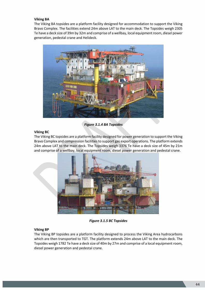
Viking BA The Viking BA topsides are a platform facility designed for accommodation to support the Viking Bravo Complex. The facilities extend 24m above LAT to the main deck. The Topsides weigh 2305 Te have a deck size of 39m by 32m and comprise of a wellbay, local equipment room, diesel power generation, pedestal crane and Helideck.
Figure 3.1.4 BA Topsides
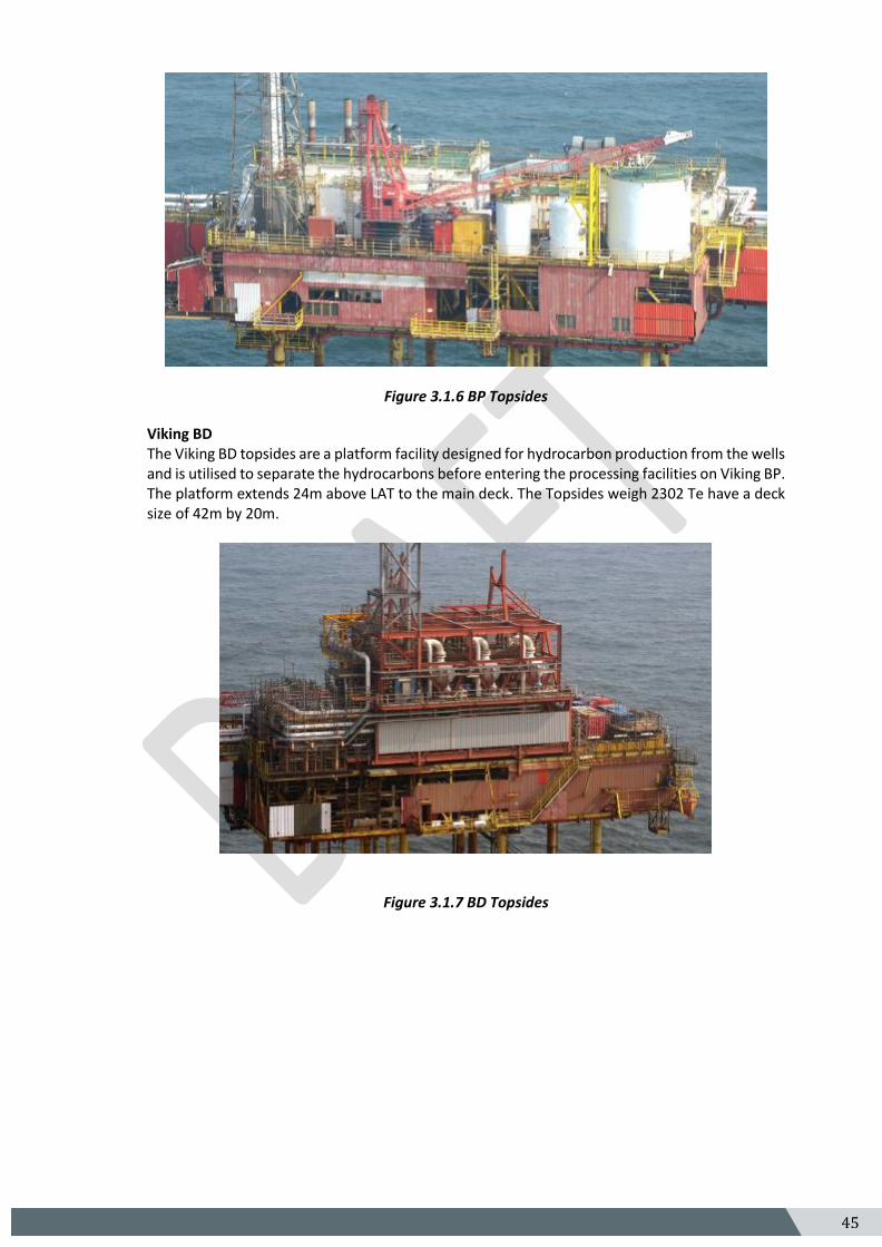
Viking BC The Viking BC topsides are a platform facility designed for power generation to support the Viking Bravo Complex and compression facilities to support gas export operations. The platform extends 24m above LAT to the main deck. The Topsides weigh 3376 Te have a deck size of 45m by 21m and comprise of a wellbay, local equipment room, diesel power generation and pedestal crane.
Figure 3.1.5 BC Topsides
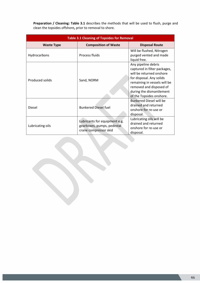
Viking BP The Viking BP topsides are a platform facility designed to process the Viking Area hydrocarbons which are then transported to TGT. The platform extends 24m above LAT to the main deck. The Topsides weigh 1782 Te have a deck size of 40m by 27m and comprise of a local equipment room, diesel power generation and pedestal crane.
45 5
Figure 3.1.6 BP Topsides
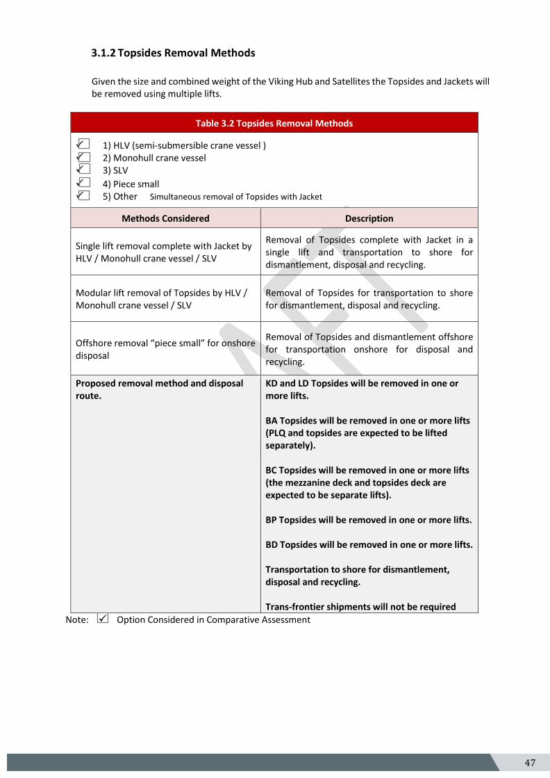
Viking BD The Viking BD topsides are a platform facility designed for hydrocarbon production from the wells and is utilised to separate the hydrocarbons before entering the processing facilities on Viking BP. The platform extends 24m above LAT to the main deck. The Topsides weigh 2302 Te have a deck size of 42m by 20m.
Figure 3.1.7 BD Topsides
46 5
Preparation / Cleaning: Table 3.1 describes the methods that will be used to flush, purge and clean the topsides offshore, prior to removal to shore.
Table 3.1 Cleaning of Topsides for Removal
Waste Type Composition of Waste Disposal Route
Hydrocarbons Process fluids Will be flushed, Nitrogen purged vented and made liquid free.
Produced solids Sand, NORM
Any pipeline debris captured in filter packages, will be returned onshore for disposal. Any solids remaining in vessels will be removed and disposed of during the dismantlement of the Topsides onshore.
Diesel Bunkered Diesel fuel
Bunkered Diesel will be drained and returned onshore for re-use or disposal.
Lubricating oils Lubricants for equipment e.g. gearboxes, pumps, pedestal crane compressor skid
Lubricating oils will be drained and returned onshore for re-use or disposal.
47 5
3.1.2 Topsides Removal Methods
Given the size and combined weight of the Viking Hub and Satellites the Topsides and Jackets will be removed using multiple lifts.
Table 3.2 Topsides Removal Methods
1) HLV (semi-submersible crane vessel ) 2) Monohull crane vessel 3) SLV
4) Piece small 5) Other Simultaneous removal of Topsides with Jacket
Methods Considered Description
Single lift removal complete with Jacket by HLV / Monohull crane vessel / SLV
Removal of Topsides complete with Jacket in a single lift and transportation to shore for dismantlement, disposal and recycling.
Modular lift removal of Topsides by HLV / Monohull crane vessel / SLV
Removal of Topsides for transportation to shore for dismantlement, disposal and recycling.
Offshore removal “piece small” for onshore disposal
Removal of Topsides and dismantlement offshore for transportation onshore for disposal and recycling.
Proposed removal method and disposal route.
KD and LD Topsides will be removed in one or more lifts. BA Topsides will be removed in one or more lifts (PLQ and topsides are expected to be lifted separately). BC Topsides will be removed in one or more lifts (the mezzanine deck and topsides deck are expected to be separate lifts). BP Topsides will be removed in one or more lifts. BD Topsides will be removed in one or more lifts. Transportation to shore for dismantlement, disposal and recycling. Trans-frontier shipments will not be required
Note:Option Considered in Comparative Assessment
48 5
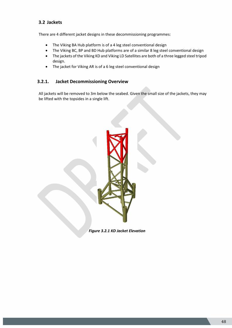
3.2 Jackets
There are 4 different jacket designs in these decommissioning programmes:
• The Viking BA Hub platform is of a 4 leg steel conventional design
• The Viking BC, BP and BD Hub platforms are of a similar 8 leg steel conventional design
• The jackets of the Viking KD and Viking LD Satellites are both of a three legged steel tripod design.
• The jacket for Viking AR is of a 6 leg steel conventional design
3.2.1. Jacket Decommissioning Overview
All jackets will be removed to 3m below the seabed. Given the small size of the jackets, they may be lifted with the topsides in a single lift.
Figure 3.2.1 KD Jacket Elevation
49 5
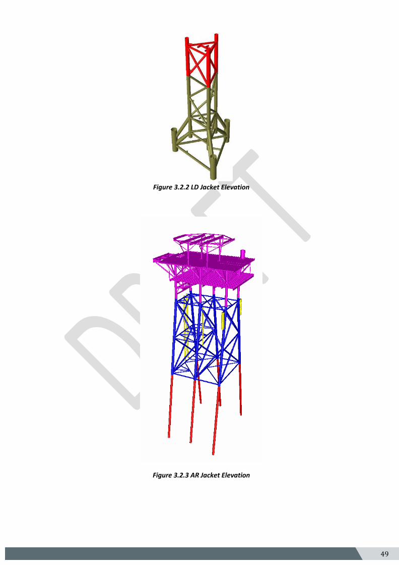
Figure 3.2.2 LD Jacket Elevation
Figure 3.2.3 AR Jacket Elevation
50 5
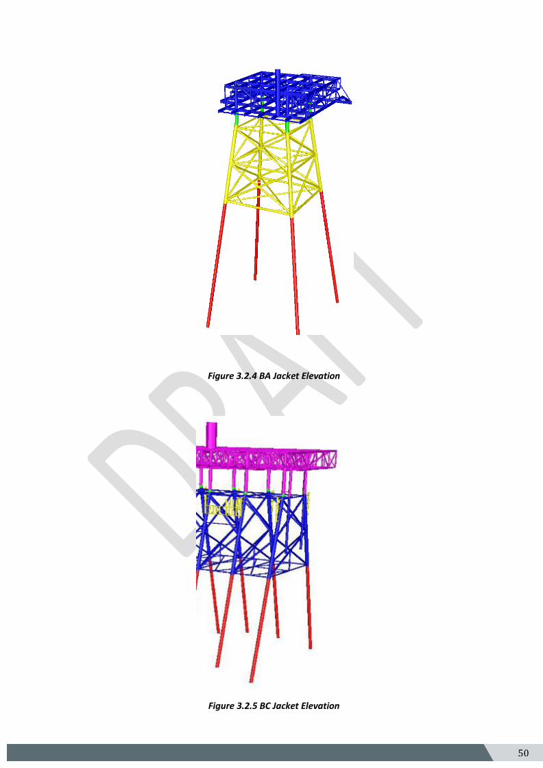
Figure 3.2.4 BA Jacket Elevation
Figure 3.2.5 BC Jacket Elevation
51 5
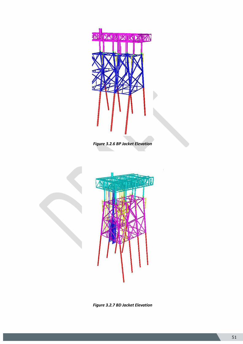
Figure 3.2.6 BP Jacket Elevation
Figure 3.2.7 BD Jacket Elevation
52 5
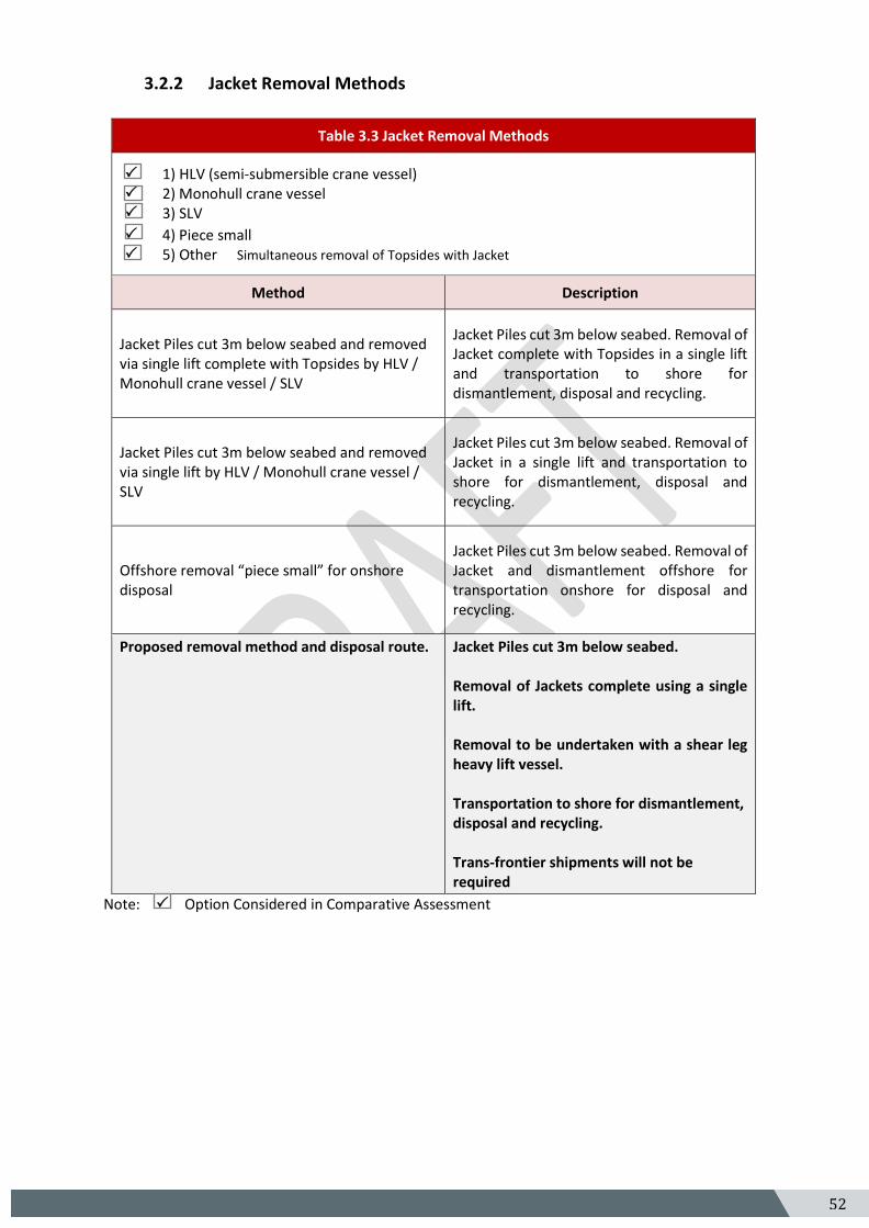
3.2.2 Jacket Removal Methods
Table 3.3 Jacket Removal Methods
1) HLV (semi-submersible crane vessel) 2) Monohull crane vessel 3) SLV
4) Piece small 5) Other Simultaneous removal of Topsides with Jacket
Method Description
Jacket Piles cut 3m below seabed and removed via single lift complete with Topsides by HLV / Monohull crane vessel / SLV
Jacket Piles cut 3m below seabed. Removal of Jacket complete with Topsides in a single lift and transportation to shore for dismantlement, disposal and recycling.
Jacket Piles cut 3m below seabed and removed via single lift by HLV / Monohull crane vessel / SLV
Jacket Piles cut 3m below seabed. Removal of Jacket in a single lift and transportation to shore for dismantlement, disposal and recycling.
Offshore removal “piece small” for onshore disposal
Jacket Piles cut 3m below seabed. Removal of Jacket and dismantlement offshore for transportation onshore for disposal and recycling.
Proposed removal method and disposal route.
Jacket Piles cut 3m below seabed. Removal of Jackets complete using a single lift. Removal to be undertaken with a shear leg heavy lift vessel. Transportation to shore for dismantlement, disposal and recycling. Trans-frontier shipments will not be required
Note:Option Considered in Comparative Assessment
53 5
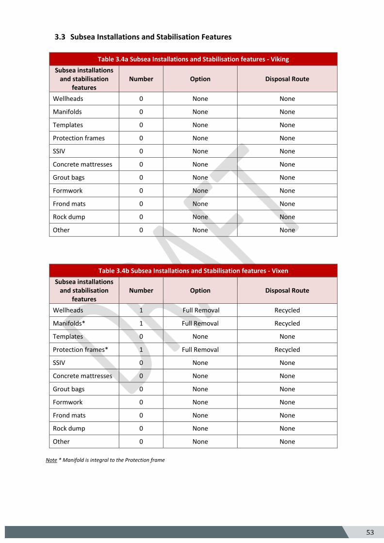
3.3 Subsea Installations and Stabilisation Features
Table 3.4a Subsea Installations and Stabilisation features - Viking
Subsea installations and stabilisation
features Number Option Disposal Route
Wellheads 0 None None
Manifolds 0 None None
Templates 0 None None
Protection frames 0 None None
SSIV 0 None None
Concrete mattresses 0 None None
Grout bags 0 None None
Formwork 0 None None
Frond mats 0 None None
Rock dump 0 None None
Other 0 None None
Table 3.4b Subsea Installations and Stabilisation features - Vixen
Subsea installations and stabilisation
features Number Option Disposal Route
Wellheads 1 Full Removal Recycled
Manifolds* 1 Full Removal Recycled
Templates 0 None None
Protection frames* 1 Full Removal Recycled
SSIV 0 None None
Concrete mattresses 0 None None
Grout bags 0 None None
Formwork 0 None None
Frond mats 0 None None
Rock dump 0 None None
Other 0 None None
Note * Manifold is integral to the Protection frame
54 5
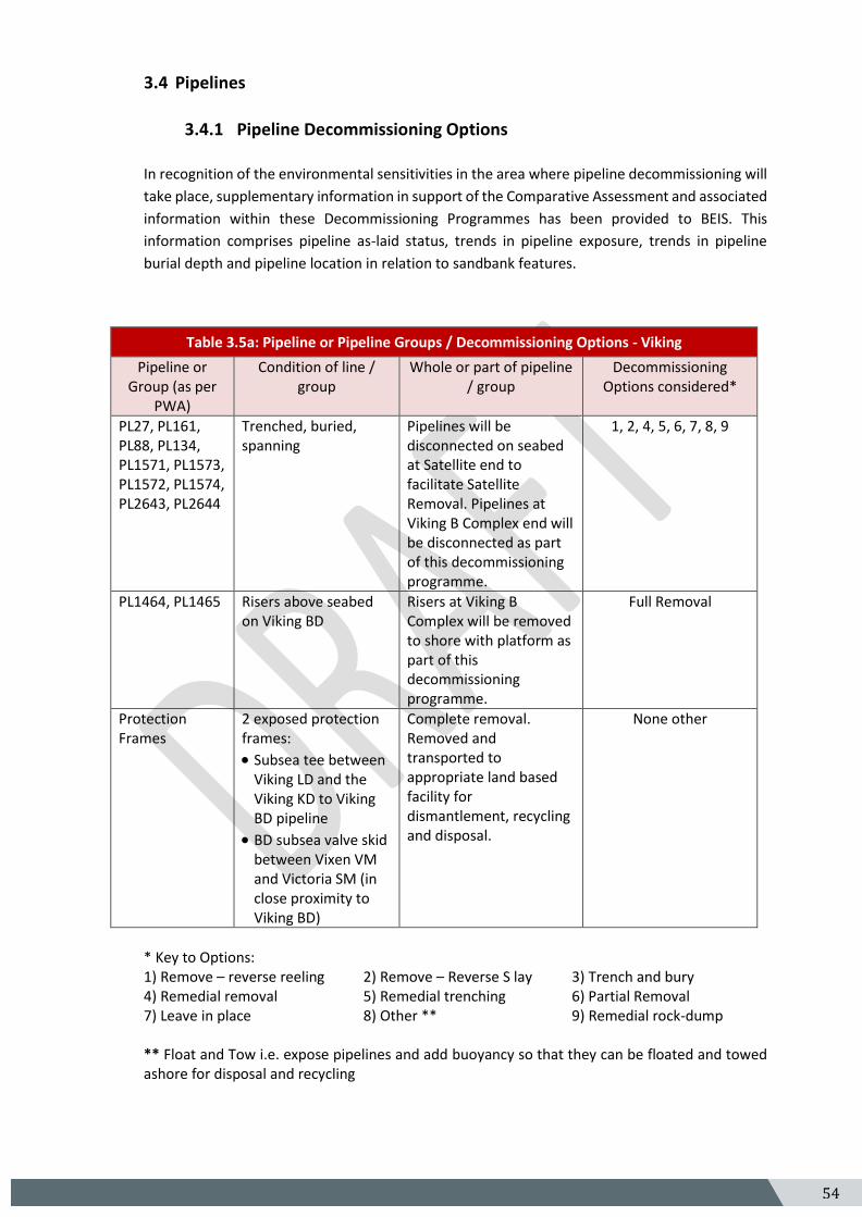
3.4 Pipelines
3.4.1 Pipeline Decommissioning Options
In recognition of the environmental sensitivities in the area where pipeline decommissioning will
take place, supplementary information in support of the Comparative Assessment and associated
information within these Decommissioning Programmes has been provided to BEIS. This
information comprises pipeline as-laid status, trends in pipeline exposure, trends in pipeline
burial depth and pipeline location in relation to sandbank features.
Table 3.5a: Pipeline or Pipeline Groups / Decommissioning Options - Viking
Pipeline or Group (as per
PWA)
Condition of line / group
Whole or part of pipeline / group
Decommissioning Options considered*
PL27, PL161, PL88, PL134, PL1571, PL1573, PL1572, PL1574, PL2643, PL2644
Trenched, buried, spanning
Pipelines will be disconnected on seabed at Satellite end to facilitate Satellite Removal. Pipelines at Viking B Complex end will be disconnected as part of this decommissioning programme.
1, 2, 4, 5, 6, 7, 8, 9
PL1464, PL1465 Risers above seabed on Viking BD
Risers at Viking B Complex will be removed to shore with platform as part of this decommissioning programme.
Full Removal
Protection Frames
2 exposed protection frames:
• Subsea tee between Viking LD and the Viking KD to Viking BD pipeline
• BD subsea valve skid between Vixen VM and Victoria SM (in close proximity to Viking BD)
Complete removal. Removed and transported to appropriate land based facility for dismantlement, recycling and disposal.
None other
* Key to Options: 1) Remove – reverse reeling 2) Remove – Reverse S lay 3) Trench and bury 4) Remedial removal 5) Remedial trenching 6) Partial Removal 7) Leave in place 8) Other ** 9) Remedial rock-dump ** Float and Tow i.e. expose pipelines and add buoyancy so that they can be floated and towed ashore for disposal and recycling
55 5
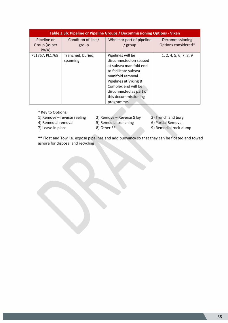
Table 3.5b: Pipeline or Pipeline Groups / Decommissioning Options - Vixen
Pipeline or Group (as per
PWA)
Condition of line / group
Whole or part of pipeline / group
Decommissioning Options considered*
PL1767, PL1768 Trenched, buried, spanning
Pipelines will be disconnected on seabed at subsea manifold end to facilitate subsea manifold removal. Pipelines at Viking B Complex end will be disconnected as part of this decommissioning programme.
1, 2, 4, 5, 6, 7, 8, 9
* Key to Options: 1) Remove – reverse reeling 2) Remove – Reverse S lay 3) Trench and bury 4) Remedial removal 5) Remedial trenching 6) Partial Removal 7) Leave in place 8) Other ** 9) Remedial rock-dump ** Float and Tow i.e. expose pipelines and add buoyancy so that they can be floated and towed ashore for disposal and recycling
56 5
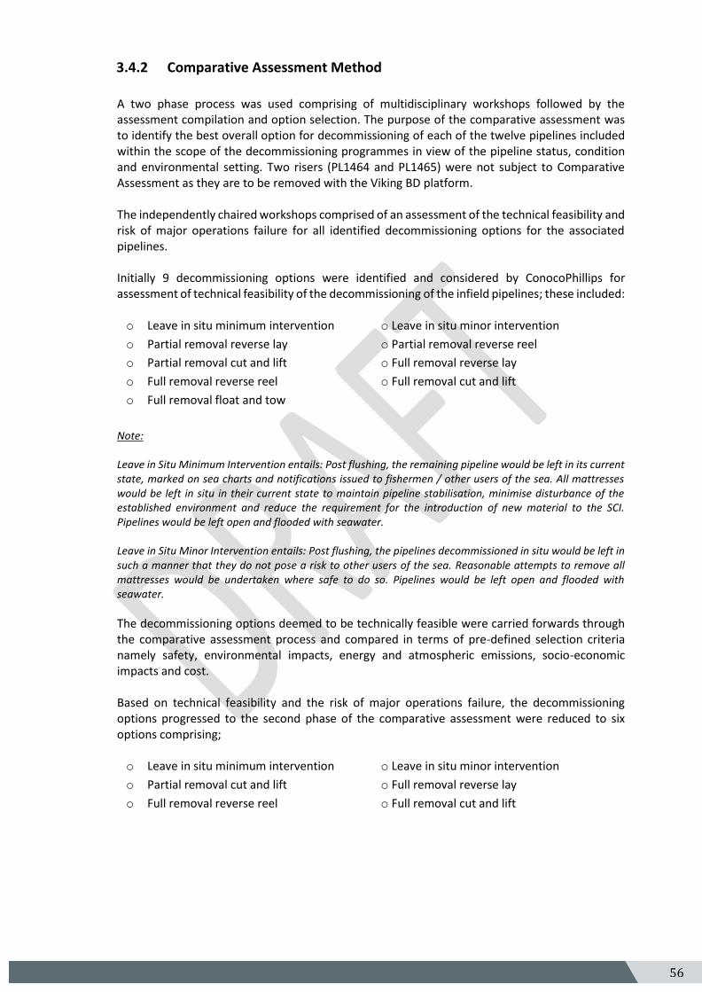
3.4.2 Comparative Assessment Method
A two phase process was used comprising of multidisciplinary workshops followed by the assessment compilation and option selection. The purpose of the comparative assessment was to identify the best overall option for decommissioning of each of the twelve pipelines included within the scope of the decommissioning programmes in view of the pipeline status, condition and environmental setting. Two risers (PL1464 and PL1465) were not subject to Comparative Assessment as they are to be removed with the Viking BD platform. The independently chaired workshops comprised of an assessment of the technical feasibility and risk of major operations failure for all identified decommissioning options for the associated pipelines. Initially 9 decommissioning options were identified and considered by ConocoPhillips for assessment of technical feasibility of the decommissioning of the infield pipelines; these included: o Leave in situ minimum intervention o Leave in situ minor intervention
o Partial removal reverse lay o Partial removal reverse reel
o Partial removal cut and lift o Full removal reverse lay
o Full removal reverse reel o Full removal cut and lift
o Full removal float and tow
Note: Leave in Situ Minimum Intervention entails: Post flushing, the remaining pipeline would be left in its current state, marked on sea charts and notifications issued to fishermen / other users of the sea. All mattresses would be left in situ in their current state to maintain pipeline stabilisation, minimise disturbance of the established environment and reduce the requirement for the introduction of new material to the SCI. Pipelines would be left open and flooded with seawater. Leave in Situ Minor Intervention entails: Post flushing, the pipelines decommissioned in situ would be left in such a manner that they do not pose a risk to other users of the sea. Reasonable attempts to remove all mattresses would be undertaken where safe to do so. Pipelines would be left open and flooded with seawater.
The decommissioning options deemed to be technically feasible were carried forwards through the comparative assessment process and compared in terms of pre-defined selection criteria namely safety, environmental impacts, energy and atmospheric emissions, socio-economic impacts and cost. Based on technical feasibility and the risk of major operations failure, the decommissioning options progressed to the second phase of the comparative assessment were reduced to six options comprising; o Leave in situ minimum intervention o Leave in situ minor intervention
o Partial removal cut and lift o Full removal reverse lay
o Full removal reverse reel o Full removal cut and lift
57 5
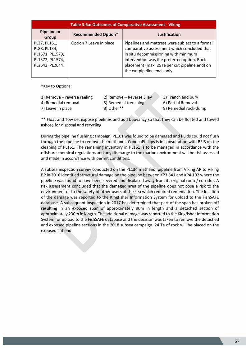
Table 3.6a: Outcomes of Comparative Assessment - Viking
Pipeline or Group
Recommended Option* Justification
PL27, PL161, PL88, PL134, PL1571, PL1573, PL1572, PL1574, PL2643, PL2644
Option 7 Leave in place Pipelines and mattress were subject to a formal comparative assessment which concluded that in situ decommissioning with minimum intervention was the preferred option. Rock-placement (max. 25Te per cut pipeline end) on the cut pipeline ends only.
*Key to Options: 1) Remove – reverse reeling 2) Remove – Reverse S lay 3) Trench and bury 4) Remedial removal 5) Remedial trenching 6) Partial Removal 7) Leave in place 8) Other** 9) Remedial rock-dump ** Float and Tow i.e. expose pipelines and add buoyancy so that they can be floated and towed ashore for disposal and recycling
During the pipeline flushing campaign, PL161 was found to be damaged and fluids could not flush through the pipeline to remove the methanol. ConocoPhillips is in consultation with BEIS on the cleaning of PL161. The remaining inventory in PL161 is to be managed in accordance with the offshore chemical regulations and any discharge to the marine environment will be risk assessed and made in accordance with permit conditions. A subsea inspection survey conducted on the PL134 methanol pipeline from Viking AR to Viking BP in 2016 identified structural damage on the pipeline between KP3.841 and KP4.102 where the pipeline was found to have been severed and displaced away from its original route/ corridor. A risk assessment concluded that the damaged area of the pipeline does not pose a risk to the environment or to the safety of other users of the sea which required remediation. The location of the damage was reported to the Kingfisher Information System for upload to the FishSAFE database. A subsequent inspection in 2017 has determined that part of the span has broken off resulting in an exposed span of approximately 90m in length and a detached section of approximately 230m in length. The additional damage was reported to the Kingfisher Information System for upload to the FishSAFE database and the decision was taken to remove the detached and exposed pipeline sections in the 2018 subsea campaign. 24 Te of rock will be placed on the exposed cut end.
58 5
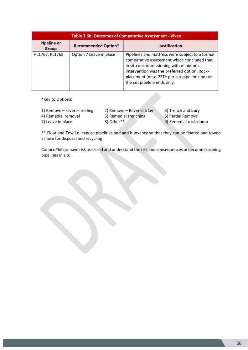
Table 3.6b: Outcomes of Comparative Assessment - Vixen
Pipeline or Group
Recommended Option* Justification
PL1767, PL1768 Option 7 Leave in place Pipelines and mattress were subject to a formal comparative assessment which concluded that in situ decommissioning with minimum intervention was the preferred option. Rock-placement (max. 25Te per cut pipeline end) on the cut pipeline ends only.
*Key to Options: 1) Remove – reverse reeling 2) Remove – Reverse S lay 3) Trench and bury 4) Remedial removal 5) Remedial trenching 6) Partial Removal 7) Leave in place 8) Other** 9) Remedial rock-dump ** Float and Tow i.e. expose pipelines and add buoyancy so that they can be floated and towed ashore for disposal and recycling ConocoPhillips have risk assessed and understand the risk and consequences of decommissioning pipelines in situ.
59 5
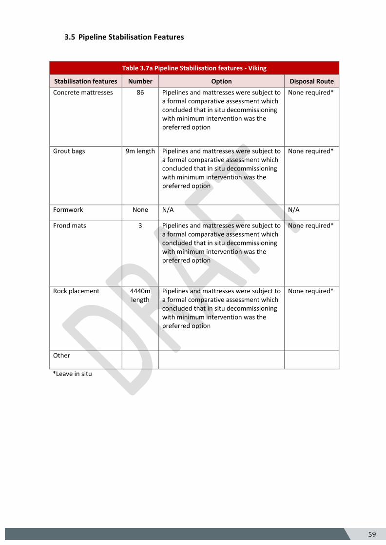
3.5 Pipeline Stabilisation Features
Table 3.7a Pipeline Stabilisation features - Viking
Stabilisation features Number Option Disposal Route
Concrete mattresses 86 Pipelines and mattresses were subject to a formal comparative assessment which concluded that in situ decommissioning with minimum intervention was the preferred option
None required*
Grout bags 9m length Pipelines and mattresses were subject to a formal comparative assessment which concluded that in situ decommissioning with minimum intervention was the preferred option
None required*
Formwork None N/A N/A
Frond mats 3 Pipelines and mattresses were subject to a formal comparative assessment which concluded that in situ decommissioning with minimum intervention was the preferred option
None required*
Rock placement 4440m length
Pipelines and mattresses were subject to a formal comparative assessment which concluded that in situ decommissioning with minimum intervention was the preferred option
None required*
Other
*Leave in situ
60 5
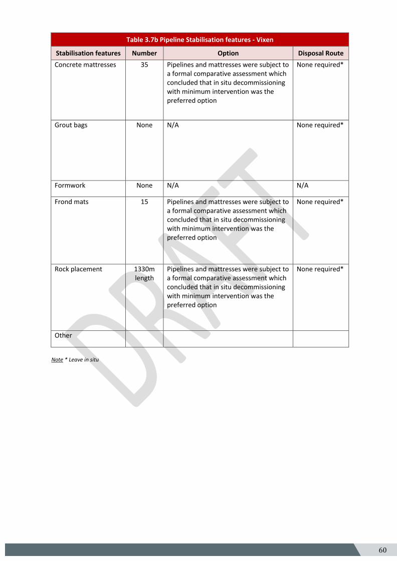
Table 3.7b Pipeline Stabilisation features - Vixen
Stabilisation features Number Option Disposal Route
Concrete mattresses 35 Pipelines and mattresses were subject to a formal comparative assessment which concluded that in situ decommissioning with minimum intervention was the preferred option
None required*
Grout bags None N/A None required*
Formwork None N/A N/A
Frond mats 15 Pipelines and mattresses were subject to a formal comparative assessment which concluded that in situ decommissioning with minimum intervention was the preferred option
None required*
Rock placement 1330m length
Pipelines and mattresses were subject to a formal comparative assessment which concluded that in situ decommissioning with minimum intervention was the preferred option
None required*
Other
Note * Leave in situ
61 5
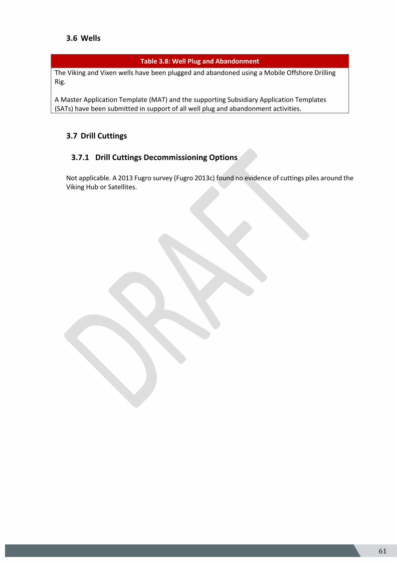
3.6 Wells
Table 3.8: Well Plug and Abandonment
The Viking and Vixen wells have been plugged and abandoned using a Mobile Offshore Drilling Rig. A Master Application Template (MAT) and the supporting Subsidiary Application Templates (SATs) have been submitted in support of all well plug and abandonment activities.
3.7 Drill Cuttings
3.7.1 Drill Cuttings Decommissioning Options
Not applicable. A 2013 Fugro survey (Fugro 2013c) found no evidence of cuttings piles around the Viking Hub or Satellites.
62 5
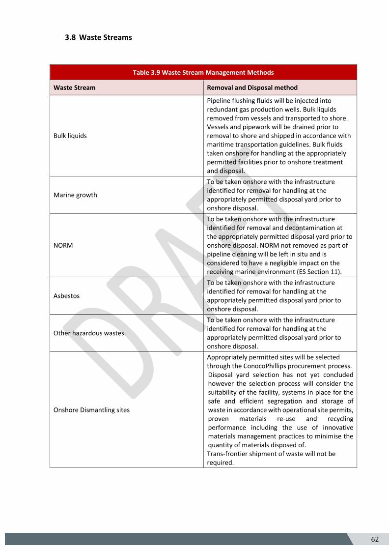
3.8 Waste Streams
Table 3.9 Waste Stream Management Methods
Waste Stream Removal and Disposal method
Bulk liquids
Pipeline flushing fluids will be injected into redundant gas production wells. Bulk liquids removed from vessels and transported to shore. Vessels and pipework will be drained prior to removal to shore and shipped in accordance with maritime transportation guidelines. Bulk fluids taken onshore for handling at the appropriately permitted facilities prior to onshore treatment and disposal.
Marine growth
To be taken onshore with the infrastructure identified for removal for handling at the appropriately permitted disposal yard prior to onshore disposal.
NORM
To be taken onshore with the infrastructure identified for removal and decontamination at the appropriately permitted disposal yard prior to onshore disposal. NORM not removed as part of pipeline cleaning will be left in situ and is considered to have a negligible impact on the receiving marine environment (ES Section 11).
Asbestos
To be taken onshore with the infrastructure identified for removal for handling at the appropriately permitted disposal yard prior to onshore disposal.
Other hazardous wastes
To be taken onshore with the infrastructure identified for removal for handling at the appropriately permitted disposal yard prior to onshore disposal.
Onshore Dismantling sites
Appropriately permitted sites will be selected through the ConocoPhillips procurement process. Disposal yard selection has not yet concluded however the selection process will consider the suitability of the facility, systems in place for the safe and efficient segregation and storage of waste in accordance with operational site permits, proven materials re-use and recycling performance including the use of innovative materials management practices to minimise the quantity of materials disposed of. Trans-frontier shipment of waste will not be required.
63 5
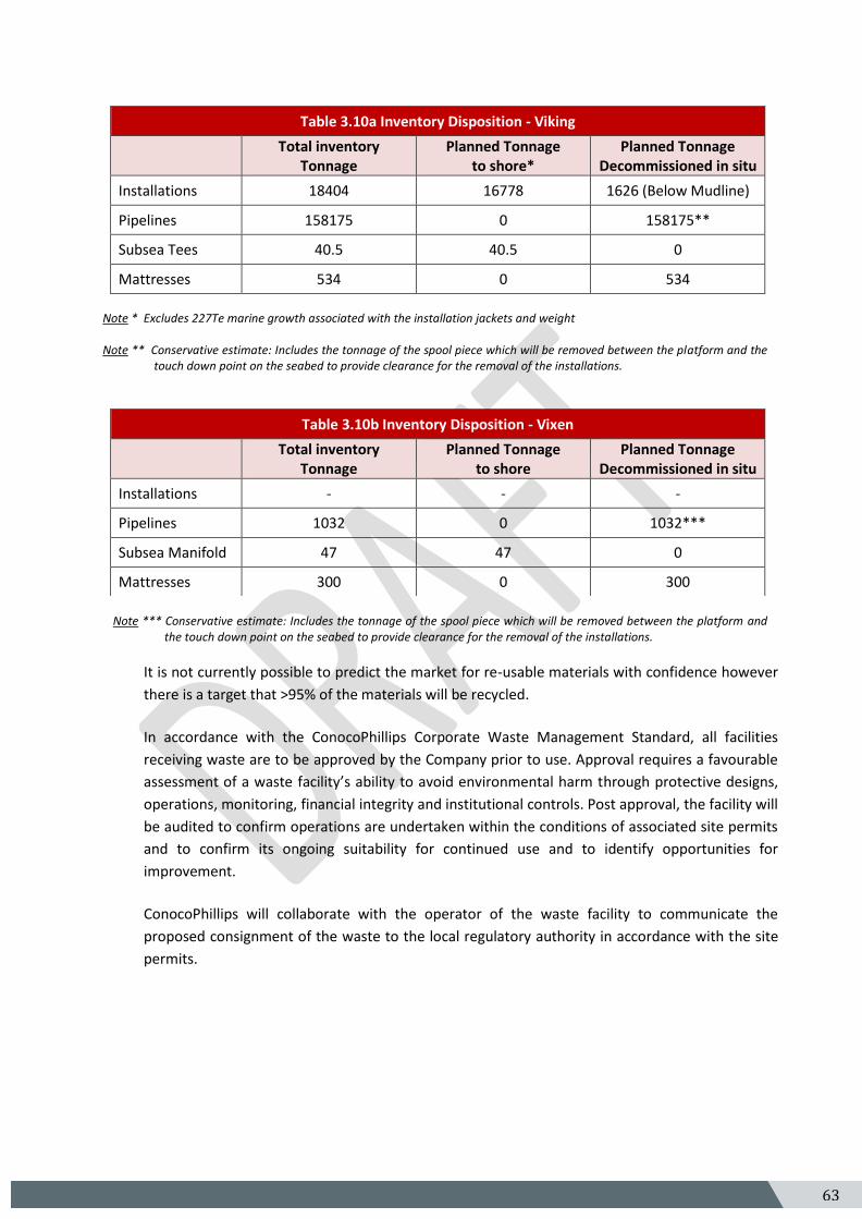
Note * Excludes 227Te marine growth associated with the installation jackets and weight Note ** Conservative estimate: Includes the tonnage of the spool piece which will be removed between the platform and the
touch down point on the seabed to provide clearance for the removal of the installations.
Note *** Conservative estimate: Includes the tonnage of the spool piece which will be removed between the platform and
the touch down point on the seabed to provide clearance for the removal of the installations.
It is not currently possible to predict the market for re-usable materials with confidence however
there is a target that >95% of the materials will be recycled.
In accordance with the ConocoPhillips Corporate Waste Management Standard, all facilities
receiving waste are to be approved by the Company prior to use. Approval requires a favourable
assessment of a waste facility’s ability to avoid environmental harm through protective designs,
operations, monitoring, financial integrity and institutional controls. Post approval, the facility will
be audited to confirm operations are undertaken within the conditions of associated site permits
and to confirm its ongoing suitability for continued use and to identify opportunities for
improvement.
ConocoPhillips will collaborate with the operator of the waste facility to communicate the
proposed consignment of the waste to the local regulatory authority in accordance with the site
permits.
Table 3.10a Inventory Disposition - Viking
Total inventory Tonnage
Planned Tonnage to shore*
Planned Tonnage Decommissioned in situ
Installations 18404 16778 1626 (Below Mudline)
Pipelines 158175 0 158175**
Subsea Tees 40.5 40.5 0
Mattresses 534 0 534
Table 3.10b Inventory Disposition - Vixen
Total inventory Tonnage
Planned Tonnage to shore
Planned Tonnage Decommissioned in situ
Installations - - -
Pipelines 1032 0 1032***
Subsea Manifold 47 47 0
Mattresses 300 0 300
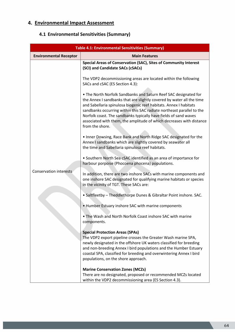
64 5
4. Environmental Impact Assessment
4.1 Environmental Sensitivities (Summary)
Table 4.1: Environmental Sensitivities (Summary)
Environmental Receptor Main Features
Conservation interests
Special Areas of Conservation (SAC), Sites of Community Interest (SCI) and Candidate SACs (cSACs) The VDP2 decommissioning areas are located within the following SACs and cSAC (ES Section 4.3): • The North Norfolk Sandbanks and Saturn Reef SAC designated for the Annex I sandbanks that are slightly covered by water all the time and Sabellaria spinulosa biogenic reef habitats. Annex I habitats sandbanks occurring within this SAC radiate northeast parallel to the Norfolk coast. The sandbanks typically have fields of sand waves associated with them, the amplitude of which decreases with distance from the shore. • Inner Dowsing, Race Bank and North Ridge SAC designated for the Annex I sandbanks which are slightly covered by seawater all the time and Sabellaria spinulosa reef habitats. • Southern North Sea cSAC identified as an area of importance for harbour porpoise (Phocoena phocena) populations. In addition, there are two inshore SACs with marine components and one inshore SAC designated for qualifying marine habitats or species in the vicinity of TGT. These SACs are: • Saltfleetby – Theddlethorpe Dunes & Gibraltar Point inshore. SAC. • Humber Estuary inshore SAC with marine components • The Wash and North Norfolk Coast inshore SAC with marine components. Special Protection Areas (SPAs) The VDP2 export pipeline crosses the Greater Wash marine SPA, newly designated in the offshore UK waters classified for breeding and non-breeding Annex I bird populations and the Humber Estuary coastal SPA, classified for breeding and overwintering Annex I bird populations, on the shore approach. Marine Conservation Zones (MCZs) There are no designated, proposed or recommended MCZs located within the VDP2 decommissioning area (ES Section 4.3).
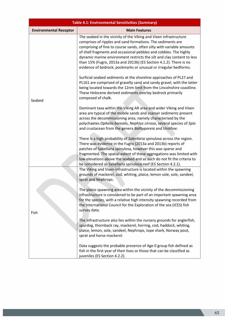
65 5
Table 4.1: Environmental Sensitivities (Summary)
Environmental Receptor Main Features
Seabed
The seabed in the vicinity of the Viking and Vixen infrastructure comprises of ripples and sand formations. The sediments are comprising of fine to course sands, often silty with variable amounts of shell fragments and occasional pebbles and cobbles. The highly dynamic marine environment restricts the silt and clay content to less than 15% (Fugro, 2013a and 2013b) (ES Section 4.1.2). There is no evidence of bedrock, pockmarks or unusual or irregular bedforms. Surficial seabed sediments at the shoreline approaches of PL27 and PL161 are comprised of gravelly sand and sandy gravel, with the latter being located towards the 12nm limit from the Lincolnshire coastline. These Holocene derived sediments overlay bedrock primarily composed of chalk. Dominant taxa within the Viking AR area and wider Viking and Vixen area are typical of the mobile sands and coarser sediments present across the decommissioning area, namely characterised by the polychaetes Ophelia borealis, Nephtys cirrosa, several species of Spio and crustacean from the genera Bathyporeia and Urothoe. There is a high probability of Sabellaria spinulosa across the region. There was evidence in the Fugro (2013a and 2013b) reports of patches of Sabellaria spinulosa, however this was sparse and fragmented. The spatial extent of these aggregations was limited with low elevations above the seabed and as such do not fit the criteria to be considered as Sabellaria spinulosa reef (ES Section 4.2.1).
Fish
The Viking and Vixen infrastructure is located within the spawning grounds of mackerel, cod, whiting, plaice, lemon sole, sole, sandeel, sprat and Nephrops. The plaice spawning area within the vicinity of the decommissioning infrastructure is considered to be part of an important spawning area for the species, with a relative high intensity spawning recorded from the International Council for the Exploration of the sea (ICES) fish survey data. The infrastructure also lies within the nursery grounds for anglerfish, spurdog, thornback ray, mackerel, herring, cod, haddock, whiting, plaice, lemon, sole, sandeel, Nephrops, tope shark, Norway pout, sprat and horse mackerel. Data suggests the probable presence of Age 0 group fish defined as fish in the first year of their lives or those that can be classified as juveniles (ES Section 4.2.2).
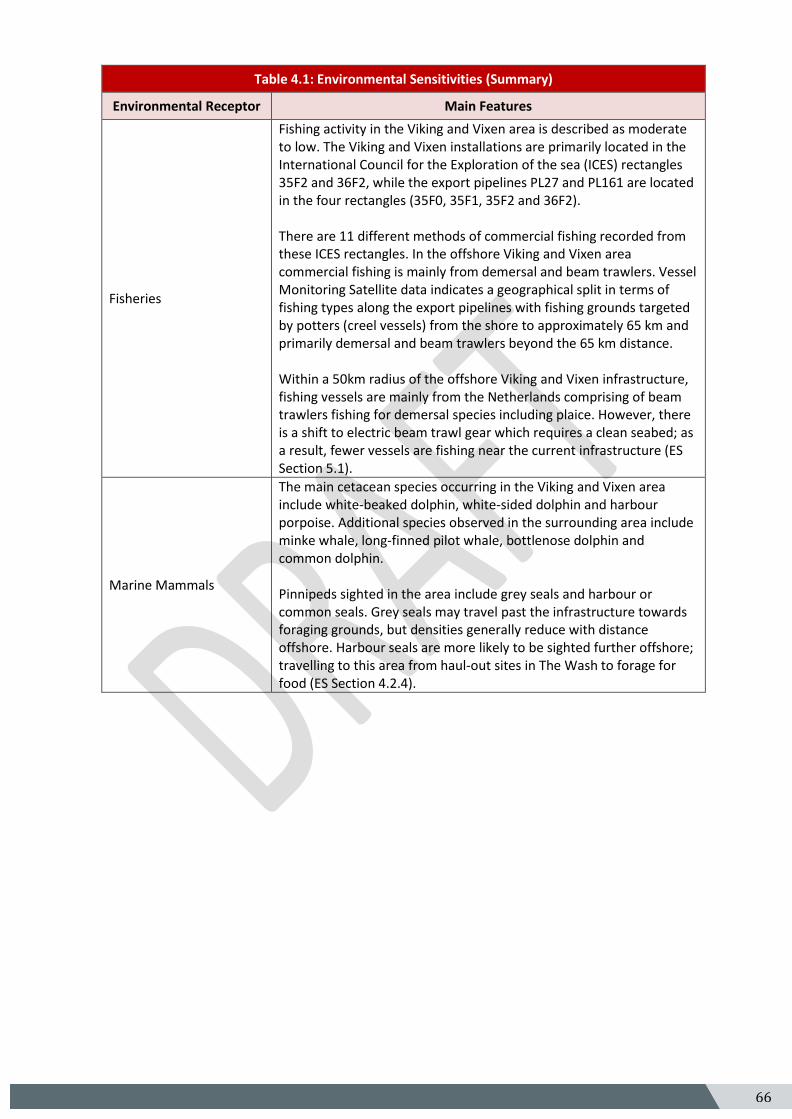
66 5
Table 4.1: Environmental Sensitivities (Summary)
Environmental Receptor Main Features
Fisheries
Fishing activity in the Viking and Vixen area is described as moderate to low. The Viking and Vixen installations are primarily located in the International Council for the Exploration of the sea (ICES) rectangles 35F2 and 36F2, while the export pipelines PL27 and PL161 are located in the four rectangles (35F0, 35F1, 35F2 and 36F2). There are 11 different methods of commercial fishing recorded from these ICES rectangles. In the offshore Viking and Vixen area commercial fishing is mainly from demersal and beam trawlers. Vessel Monitoring Satellite data indicates a geographical split in terms of fishing types along the export pipelines with fishing grounds targeted by potters (creel vessels) from the shore to approximately 65 km and primarily demersal and beam trawlers beyond the 65 km distance. Within a 50km radius of the offshore Viking and Vixen infrastructure, fishing vessels are mainly from the Netherlands comprising of beam trawlers fishing for demersal species including plaice. However, there is a shift to electric beam trawl gear which requires a clean seabed; as a result, fewer vessels are fishing near the current infrastructure (ES Section 5.1).
Marine Mammals
The main cetacean species occurring in the Viking and Vixen area include white-beaked dolphin, white-sided dolphin and harbour porpoise. Additional species observed in the surrounding area include minke whale, long-finned pilot whale, bottlenose dolphin and common dolphin. Pinnipeds sighted in the area include grey seals and harbour or common seals. Grey seals may travel past the infrastructure towards foraging grounds, but densities generally reduce with distance offshore. Harbour seals are more likely to be sighted further offshore; travelling to this area from haul-out sites in The Wash to forage for food (ES Section 4.2.4).
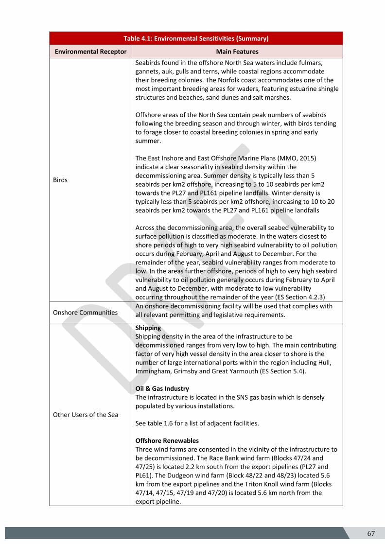
67 5
Table 4.1: Environmental Sensitivities (Summary)
Environmental Receptor Main Features
Birds
Seabirds found in the offshore North Sea waters include fulmars, gannets, auk, gulls and terns, while coastal regions accommodate their breeding colonies. The Norfolk coast accommodates one of the most important breeding areas for waders, featuring estuarine shingle structures and beaches, sand dunes and salt marshes. Offshore areas of the North Sea contain peak numbers of seabirds following the breeding season and through winter, with birds tending to forage closer to coastal breeding colonies in spring and early summer. The East Inshore and East Offshore Marine Plans (MMO, 2015) indicate a clear seasonality in seabird density within the decommissioning area. Summer density is typically less than 5 seabirds per km2 offshore, increasing to 5 to 10 seabirds per km2 towards the PL27 and PL161 pipeline landfalls. Winter density is typically less than 5 seabirds per km2 offshore, increasing to 10 to 20 seabirds per km2 towards the PL27 and PL161 pipeline landfalls Across the decommissioning area, the overall seabed vulnerability to surface pollution is classified as moderate. In the waters closest to shore periods of high to very high seabird vulnerability to oil pollution occurs during February, April and August to December. For the remainder of the year, seabird vulnerability ranges from moderate to low. In the areas further offshore, periods of high to very high seabird vulnerability to oil pollution generally occurs during February to April and August to December, with moderate to low vulnerability occurring throughout the remainder of the year (ES Section 4.2.3)
Onshore Communities An onshore decommissioning facility will be used that complies with all relevant permitting and legislative requirements.
Other Users of the Sea
Shipping Shipping density in the area of the infrastructure to be decommissioned ranges from very low to high. The main contributing factor of very high vessel density in the area closer to shore is the number of large international ports within the region including Hull, Immingham, Grimsby and Great Yarmouth (ES Section 5.4). Oil & Gas Industry The infrastructure is located in the SNS gas basin which is densely populated by various installations. See table 1.6 for a list of adjacent facilities. Offshore Renewables Three wind farms are consented in the vicinity of the infrastructure to be decommissioned. The Race Bank wind farm (Blocks 47/24 and 47/25) is located 2.2 km south from the export pipelines (PL27 and PL61). The Dudgeon wind farm (Block 48/22 and 48/23) located 5.6 km from the export pipelines and the Triton Knoll wind farm (Blocks 47/14, 47/15, 47/19 and 47/20) is located 5.6 km north from the export pipeline.
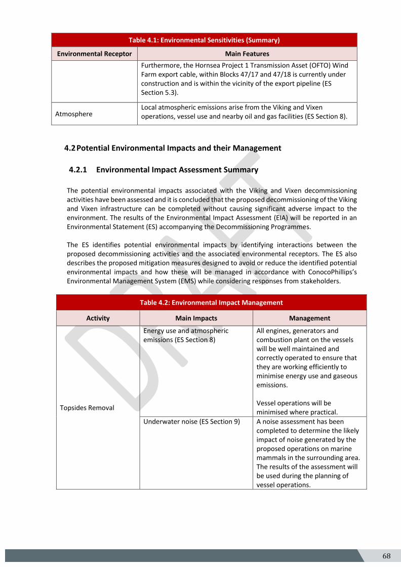
68 5
Table 4.1: Environmental Sensitivities (Summary)
Environmental Receptor Main Features
Furthermore, the Hornsea Project 1 Transmission Asset (OFTO) Wind Farm export cable, within Blocks 47/17 and 47/18 is currently under construction and is within the vicinity of the export pipeline (ES Section 5.3).
Atmosphere Local atmospheric emissions arise from the Viking and Vixen operations, vessel use and nearby oil and gas facilities (ES Section 8).
4.2 Potential Environmental Impacts and their Management
4.2.1 Environmental Impact Assessment Summary
The potential environmental impacts associated with the Viking and Vixen decommissioning activities have been assessed and it is concluded that the proposed decommissioning of the Viking and Vixen infrastructure can be completed without causing significant adverse impact to the environment. The results of the Environmental Impact Assessment (EIA) will be reported in an Environmental Statement (ES) accompanying the Decommissioning Programmes. The ES identifies potential environmental impacts by identifying interactions between the proposed decommissioning activities and the associated environmental receptors. The ES also describes the proposed mitigation measures designed to avoid or reduce the identified potential environmental impacts and how these will be managed in accordance with ConocoPhillips’s Environmental Management System (EMS) while considering responses from stakeholders.
Table 4.2: Environmental Impact Management
Activity Main Impacts Management
Topsides Removal
Energy use and atmospheric emissions (ES Section 8)
All engines, generators and combustion plant on the vessels will be well maintained and correctly operated to ensure that they are working efficiently to minimise energy use and gaseous emissions. Vessel operations will be minimised where practical.
Underwater noise (ES Section 9) A noise assessment has been completed to determine the likely impact of noise generated by the proposed operations on marine mammals in the surrounding area. The results of the assessment will be used during the planning of vessel operations.
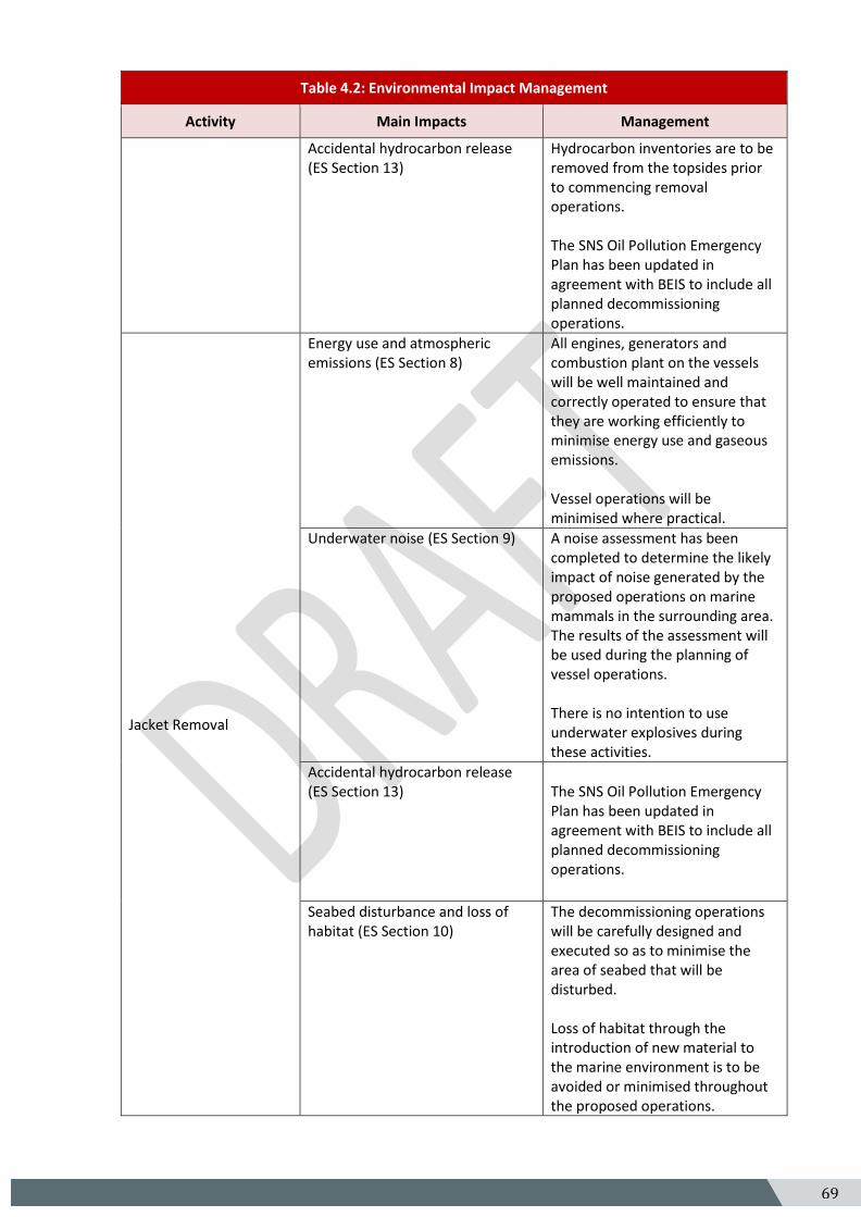
69 5
Table 4.2: Environmental Impact Management
Activity Main Impacts Management
Accidental hydrocarbon release (ES Section 13)
Hydrocarbon inventories are to be removed from the topsides prior to commencing removal operations. The SNS Oil Pollution Emergency Plan has been updated in agreement with BEIS to include all planned decommissioning operations.
Jacket Removal
Energy use and atmospheric emissions (ES Section 8)
All engines, generators and combustion plant on the vessels will be well maintained and correctly operated to ensure that they are working efficiently to minimise energy use and gaseous emissions. Vessel operations will be minimised where practical.
Underwater noise (ES Section 9) A noise assessment has been completed to determine the likely impact of noise generated by the proposed operations on marine mammals in the surrounding area. The results of the assessment will be used during the planning of vessel operations. There is no intention to use underwater explosives during these activities.
Accidental hydrocarbon release (ES Section 13)
The SNS Oil Pollution Emergency Plan has been updated in agreement with BEIS to include all planned decommissioning operations.
Seabed disturbance and loss of habitat (ES Section 10)
The decommissioning operations will be carefully designed and executed so as to minimise the area of seabed that will be disturbed. Loss of habitat through the introduction of new material to the marine environment is to be avoided or minimised throughout the proposed operations.
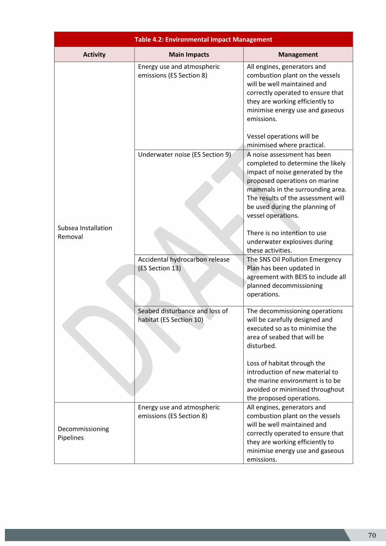
70 5
Table 4.2: Environmental Impact Management
Activity Main Impacts Management
Subsea Installation Removal
Energy use and atmospheric emissions (ES Section 8)
All engines, generators and combustion plant on the vessels will be well maintained and correctly operated to ensure that they are working efficiently to minimise energy use and gaseous emissions. Vessel operations will be minimised where practical.
Underwater noise (ES Section 9) A noise assessment has been completed to determine the likely impact of noise generated by the proposed operations on marine mammals in the surrounding area. The results of the assessment will be used during the planning of vessel operations. There is no intention to use underwater explosives during these activities.
Accidental hydrocarbon release (ES Section 13)
The SNS Oil Pollution Emergency Plan has been updated in agreement with BEIS to include all planned decommissioning operations.
Seabed disturbance and loss of habitat (ES Section 10)
The decommissioning operations will be carefully designed and executed so as to minimise the area of seabed that will be disturbed. Loss of habitat through the introduction of new material to the marine environment is to be avoided or minimised throughout the proposed operations.
Decommissioning Pipelines
Energy use and atmospheric emissions (ES Section 8)
All engines, generators and combustion plant on the vessels will be well maintained and correctly operated to ensure that they are working efficiently to minimise energy use and gaseous emissions.
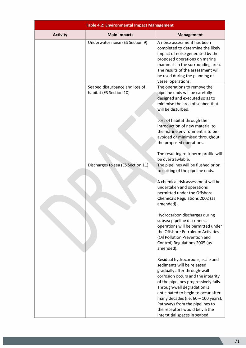
71 5
Table 4.2: Environmental Impact Management
Activity Main Impacts Management
Underwater noise (ES Section 9) A noise assessment has been completed to determine the likely impact of noise generated by the proposed operations on marine mammals in the surrounding area. The results of the assessment will be used during the planning of vessel operations.
Seabed disturbance and loss of habitat (ES Section 10)
The operations to remove the pipeline ends will be carefully designed and executed so as to minimise the area of seabed that will be disturbed. Loss of habitat through the introduction of new material to the marine environment is to be avoided or minimised throughout the proposed operations. The resulting rock berm profile will be overtrawlable.
Discharges to sea (ES Section 11) The pipelines will be flushed prior to cutting of the pipeline ends. A chemical risk assessment will be undertaken and operations permitted under the Offshore Chemicals Regulations 2002 (as amended). Hydrocarbon discharges during subsea pipeline disconnect operations will be permitted under the Offshore Petroleum Activities (Oil Pollution Prevention and Control) Regulations 2005 (as amended). Residual hydrocarbons, scale and sediments will be released gradually after through-wall corrosion occurs and the integrity of the pipelines progressively fails. Through-wall degradation is anticipated to begin to occur after many decades (i.e. 60 – 100 years). Pathways from the pipelines to the receptors would be via the interstitial spaces in seabed
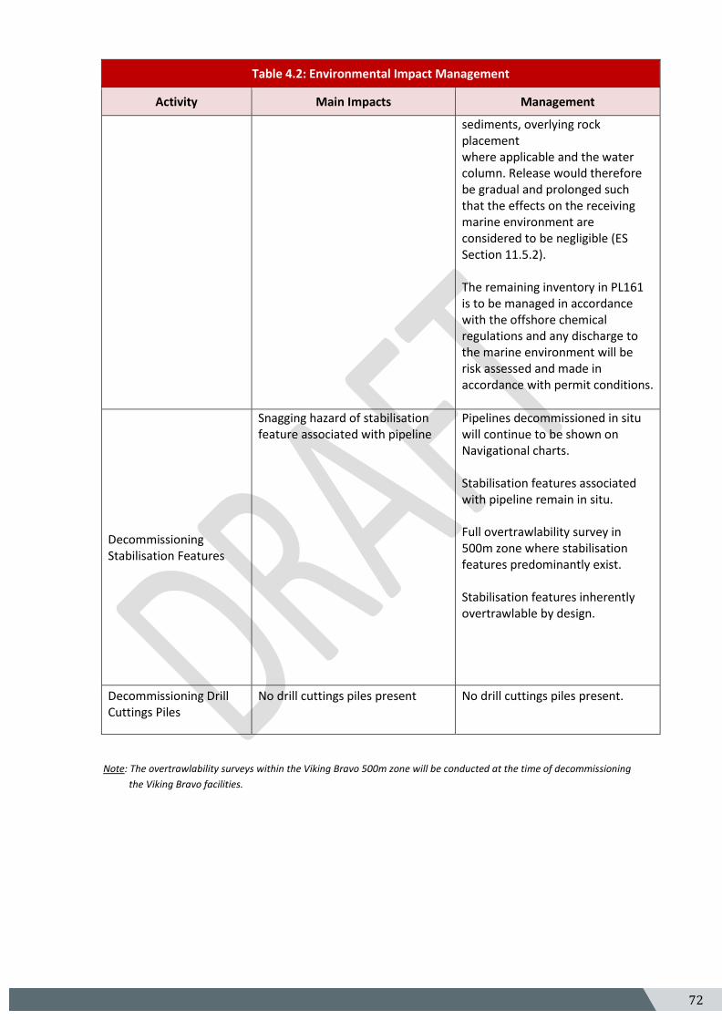
72 5
Table 4.2: Environmental Impact Management
Activity Main Impacts Management
sediments, overlying rock placement where applicable and the water column. Release would therefore be gradual and prolonged such that the effects on the receiving marine environment are considered to be negligible (ES Section 11.5.2). The remaining inventory in PL161 is to be managed in accordance with the offshore chemical regulations and any discharge to the marine environment will be risk assessed and made in accordance with permit conditions.
Decommissioning Stabilisation Features
Snagging hazard of stabilisation feature associated with pipeline
Pipelines decommissioned in situ will continue to be shown on Navigational charts. Stabilisation features associated with pipeline remain in situ. Full overtrawlability survey in 500m zone where stabilisation features predominantly exist. Stabilisation features inherently overtrawlable by design.
Decommissioning Drill Cuttings Piles
No drill cuttings piles present No drill cuttings piles present.
Note: The overtrawlability surveys within the Viking Bravo 500m zone will be conducted at the time of decommissioning
the Viking Bravo facilities.
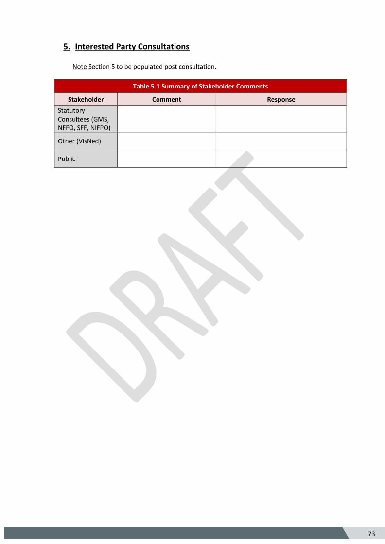
73
5
5. Interested Party Consultations Note Section 5 to be populated post consultation.
Table 5.1 Summary of Stakeholder Comments
Stakeholder Comment Response
Statutory Consultees (GMS, NFFO, SFF, NIFPO)
Other (VisNed)
Public
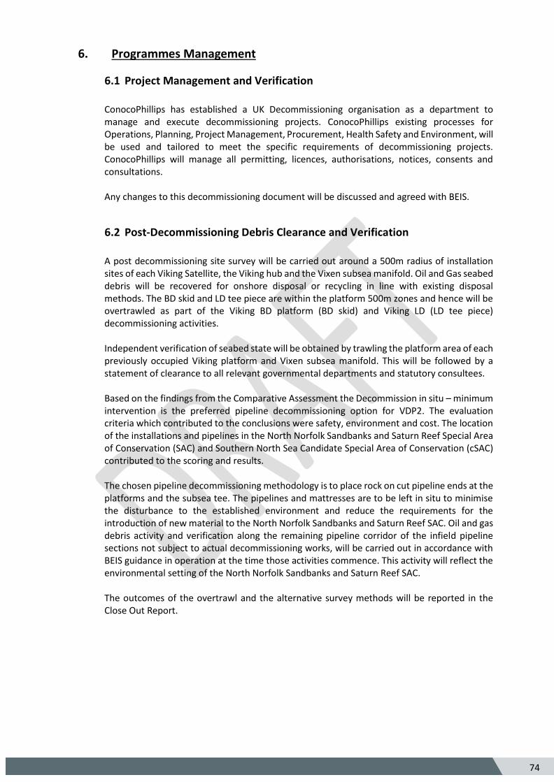
74
5
6. Programmes Management
6.1 Project Management and Verification
ConocoPhillips has established a UK Decommissioning organisation as a department to manage and execute decommissioning projects. ConocoPhillips existing processes for Operations, Planning, Project Management, Procurement, Health Safety and Environment, will be used and tailored to meet the specific requirements of decommissioning projects. ConocoPhillips will manage all permitting, licences, authorisations, notices, consents and consultations. Any changes to this decommissioning document will be discussed and agreed with BEIS.
6.2 Post-Decommissioning Debris Clearance and Verification
A post decommissioning site survey will be carried out around a 500m radius of installation sites of each Viking Satellite, the Viking hub and the Vixen subsea manifold. Oil and Gas seabed debris will be recovered for onshore disposal or recycling in line with existing disposal methods. The BD skid and LD tee piece are within the platform 500m zones and hence will be overtrawled as part of the Viking BD platform (BD skid) and Viking LD (LD tee piece) decommissioning activities. Independent verification of seabed state will be obtained by trawling the platform area of each previously occupied Viking platform and Vixen subsea manifold. This will be followed by a statement of clearance to all relevant governmental departments and statutory consultees. Based on the findings from the Comparative Assessment the Decommission in situ – minimum intervention is the preferred pipeline decommissioning option for VDP2. The evaluation criteria which contributed to the conclusions were safety, environment and cost. The location of the installations and pipelines in the North Norfolk Sandbanks and Saturn Reef Special Area of Conservation (SAC) and Southern North Sea Candidate Special Area of Conservation (cSAC) contributed to the scoring and results. The chosen pipeline decommissioning methodology is to place rock on cut pipeline ends at the platforms and the subsea tee. The pipelines and mattresses are to be left in situ to minimise the disturbance to the established environment and reduce the requirements for the introduction of new material to the North Norfolk Sandbanks and Saturn Reef SAC. Oil and gas debris activity and verification along the remaining pipeline corridor of the infield pipeline sections not subject to actual decommissioning works, will be carried out in accordance with BEIS guidance in operation at the time those activities commence. This activity will reflect the environmental setting of the North Norfolk Sandbanks and Saturn Reef SAC. The outcomes of the overtrawl and the alternative survey methods will be reported in the Close Out Report.
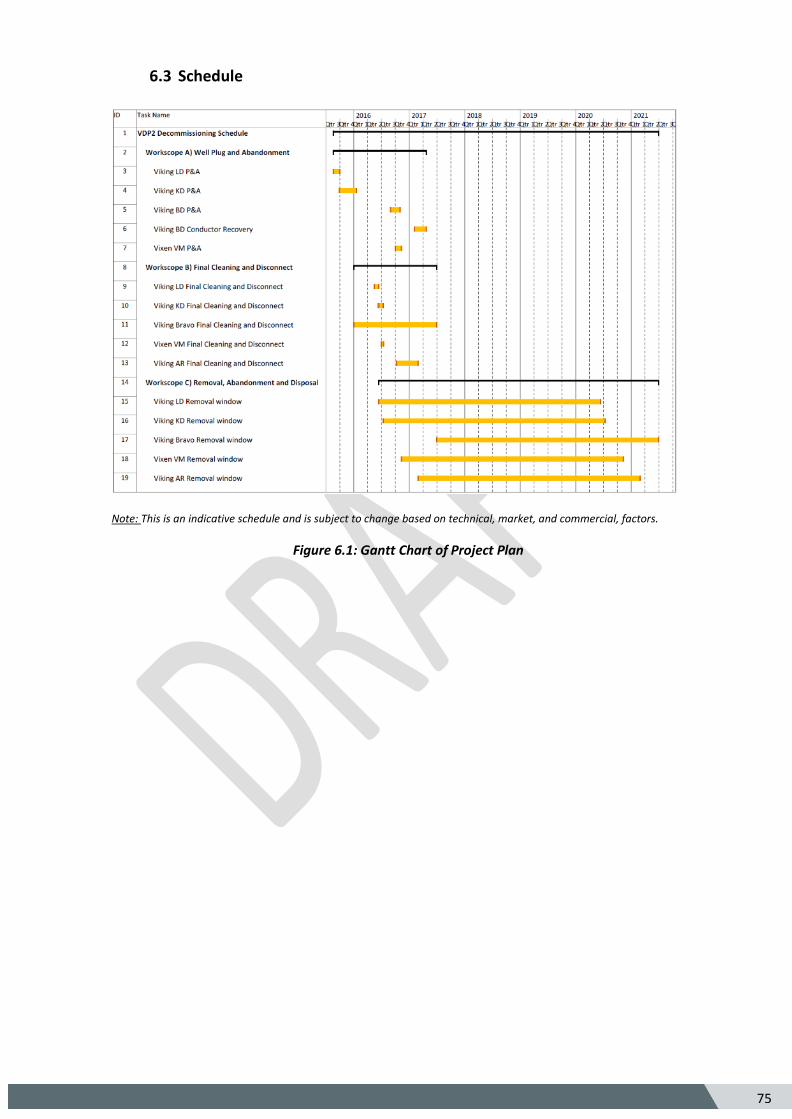
75
5
6.3 Schedule
Note: This is an indicative schedule and is subject to change based on technical, market, and commercial, factors.
Figure 6.1: Gantt Chart of Project Plan
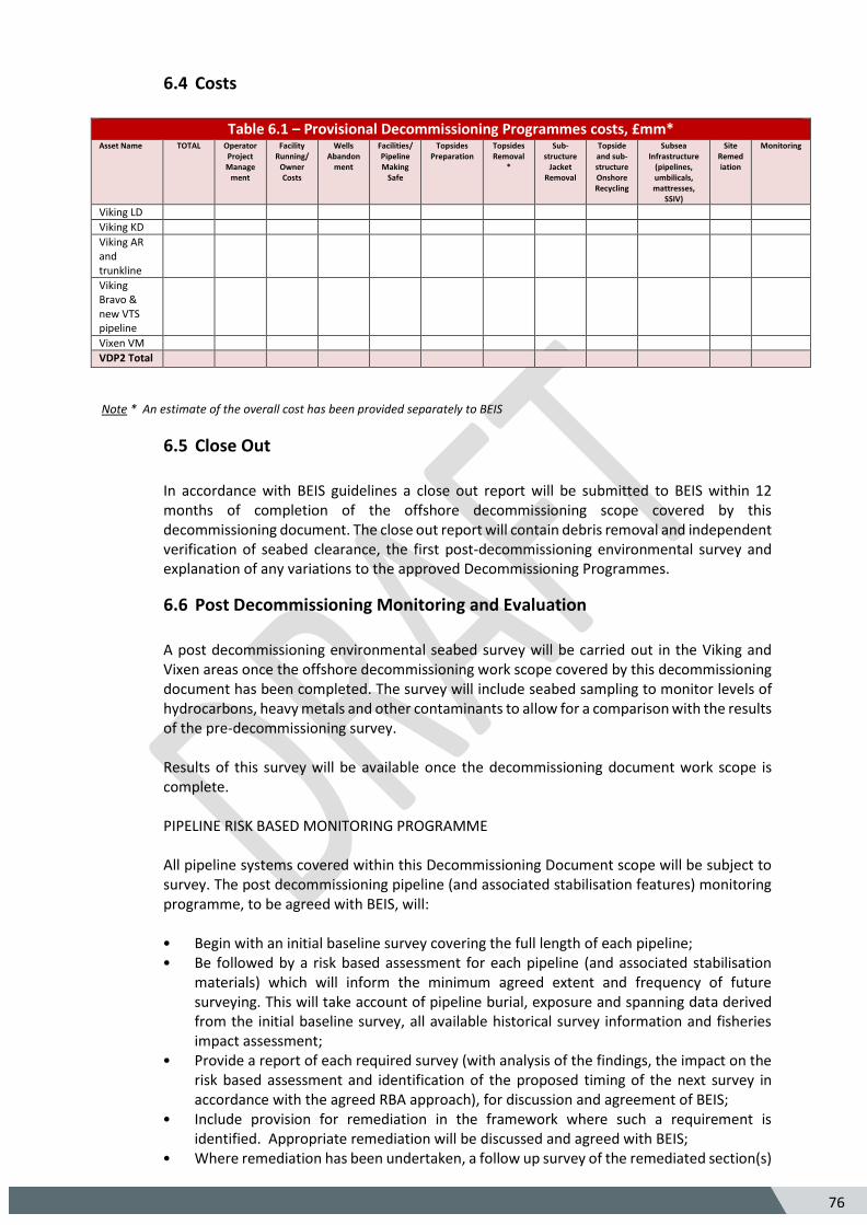
76
5
6.4 Costs
Table 6.1 – Provisional Decommissioning Programmes costs, £mm* Asset Name TOTAL Operator
Project Manage
ment
Facility Running/
Owner Costs
Wells Abandon
ment
Facilities/ Pipeline Making
Safe
Topsides Preparation
Topsides Removal
*
Sub-structure
Jacket Removal
Topside and sub-structure Onshore Recycling
Subsea Infrastructure
(pipelines, umbilicals, mattresses,
SSIV)
Site Remediation
Monitoring
Viking LD
Viking KD
Viking AR and trunkline
Viking Bravo & new VTS pipeline
Vixen VM
VDP2 Total
Note * An estimate of the overall cost has been provided separately to BEIS
6.5 Close Out
In accordance with BEIS guidelines a close out report will be submitted to BEIS within 12 months of completion of the offshore decommissioning scope covered by this decommissioning document. The close out report will contain debris removal and independent verification of seabed clearance, the first post-decommissioning environmental survey and explanation of any variations to the approved Decommissioning Programmes.
6.6 Post Decommissioning Monitoring and Evaluation
A post decommissioning environmental seabed survey will be carried out in the Viking and Vixen areas once the offshore decommissioning work scope covered by this decommissioning document has been completed. The survey will include seabed sampling to monitor levels of hydrocarbons, heavy metals and other contaminants to allow for a comparison with the results of the pre-decommissioning survey. Results of this survey will be available once the decommissioning document work scope is complete. PIPELINE RISK BASED MONITORING PROGRAMME All pipeline systems covered within this Decommissioning Document scope will be subject to survey. The post decommissioning pipeline (and associated stabilisation features) monitoring programme, to be agreed with BEIS, will:
• Begin with an initial baseline survey covering the full length of each pipeline; • Be followed by a risk based assessment for each pipeline (and associated stabilisation
materials) which will inform the minimum agreed extent and frequency of future surveying. This will take account of pipeline burial, exposure and spanning data derived from the initial baseline survey, all available historical survey information and fisheries impact assessment;
• Provide a report of each required survey (with analysis of the findings, the impact on the risk based assessment and identification of the proposed timing of the next survey in accordance with the agreed RBA approach), for discussion and agreement of BEIS;
• Include provision for remediation in the framework where such a requirement is identified. Appropriate remediation will be discussed and agreed with BEIS;
• Where remediation has been undertaken, a follow up survey of the remediated section(s)
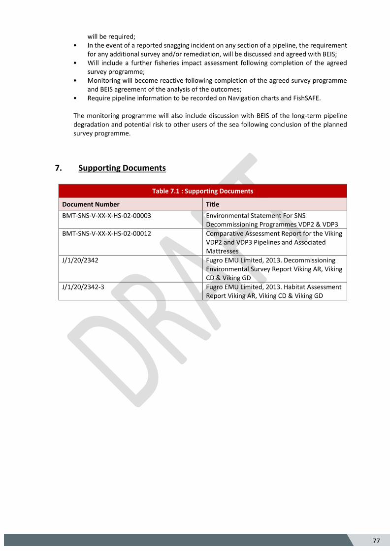
77
5
will be required; • In the event of a reported snagging incident on any section of a pipeline, the requirement
for any additional survey and/or remediation, will be discussed and agreed with BEIS; • Will include a further fisheries impact assessment following completion of the agreed
survey programme; • Monitoring will become reactive following completion of the agreed survey programme
and BEIS agreement of the analysis of the outcomes; • Require pipeline information to be recorded on Navigation charts and FishSAFE.
The monitoring programme will also include discussion with BEIS of the long-term pipeline degradation and potential risk to other users of the sea following conclusion of the planned survey programme.
7. Supporting Documents
Table 7.1 : Supporting Documents
Document Number Title
BMT-SNS-V-XX-X-HS-02-00003 Environmental Statement For SNS Decommissioning Programmes VDP2 & VDP3
BMT-SNS-V-XX-X-HS-02-00012 Comparative Assessment Report for the Viking VDP2 and VDP3 Pipelines and Associated Mattresses
J/1/20/2342 Fugro EMU Limited, 2013. Decommissioning Environmental Survey Report Viking AR, Viking CD & Viking GD
J/1/20/2342-3 Fugro EMU Limited, 2013. Habitat Assessment Report Viking AR, Viking CD & Viking GD

78
5
8. Partner Letters of Support
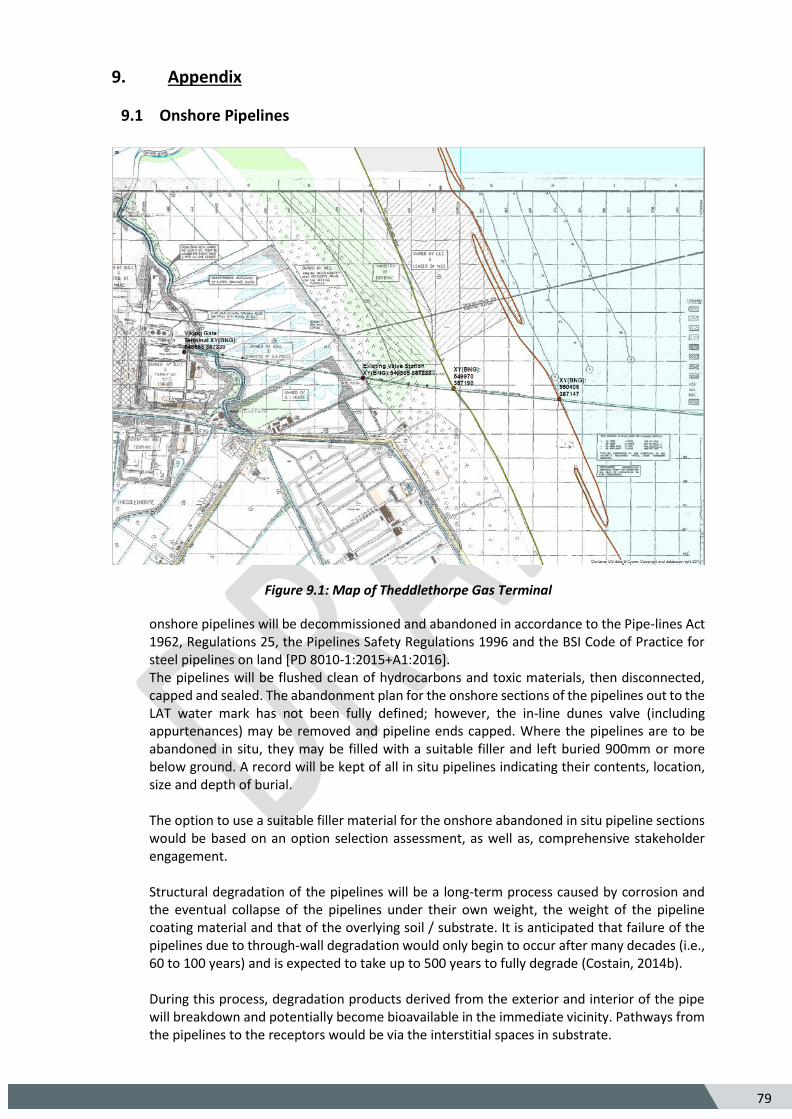
79
5
9. Appendix
9.1 Onshore Pipelines
Figure 9.1: Map of Theddlethorpe Gas Terminal
onshore pipelines will be decommissioned and abandoned in accordance to the Pipe-lines Act 1962, Regulations 25, the Pipelines Safety Regulations 1996 and the BSI Code of Practice for steel pipelines on land [PD 8010-1:2015+A1:2016]. The pipelines will be flushed clean of hydrocarbons and toxic materials, then disconnected, capped and sealed. The abandonment plan for the onshore sections of the pipelines out to the LAT water mark has not been fully defined; however, the in-line dunes valve (including appurtenances) may be removed and pipeline ends capped. Where the pipelines are to be abandoned in situ, they may be filled with a suitable filler and left buried 900mm or more below ground. A record will be kept of all in situ pipelines indicating their contents, location, size and depth of burial. The option to use a suitable filler material for the onshore abandoned in situ pipeline sections would be based on an option selection assessment, as well as, comprehensive stakeholder engagement. Structural degradation of the pipelines will be a long-term process caused by corrosion and the eventual collapse of the pipelines under their own weight, the weight of the pipeline coating material and that of the overlying soil / substrate. It is anticipated that failure of the pipelines due to through-wall degradation would only begin to occur after many decades (i.e., 60 to 100 years) and is expected to take up to 500 years to fully degrade (Costain, 2014b). During this process, degradation products derived from the exterior and interior of the pipe will breakdown and potentially become bioavailable in the immediate vicinity. Pathways from the pipelines to the receptors would be via the interstitial spaces in substrate.
80
5
The release of degradation products is expected to occur at a slow rate and therefore expected to have a minimal impact on the surrounding environment. The area that could be biologically impacted would likely be limited to a few metres on either side of the pipeline. The primary degradation products will originate from the following pipeline components:
• Pipeline scale; • Steel; • Sacrificial anodes; • Coal tar enamel coating; • Concrete coating; and • Plastic coating.
Complete failure of water filled buried pipelines has a potential for subsidence of the overlying substrate.