deconstructing the crystal structures of metalorganic frameworks
TRANSCRIPT
Published: September 15, 2011
r 2011 American Chemical Society 675 dx.doi.org/10.1021/cr200205j | Chem. Rev. 2012, 112, 675–702
REVIEW
pubs.acs.org/CR
Deconstructing the Crystal Structures of Metal�Organic Frameworksand Related Materials into Their Underlying NetsMichael O’Keeffe*,†,‡ and Omar M. Yaghi*,‡,§
†Department of Chemistry and Biochemistry, Arizona State University, Tempe, Arizona 85287, United States‡Center for Reticular Chemistry, Center for Global Mentoring, Department of Chemistry and Biochemistry,University of California�Los Angeles, 607 Charles E. Young Dr. East, Los Angeles, California 90095, United States§Graduate School of EEWS, Korea Advanced Institute of Science and Technology, Daejeon, Korea
CONTENTS
1. Introduction 6752. Identification, Description, and Characterization of
Nets 6763. Edge Nets, Augmented Nets, and the Underlying
Topology 6774. The Deconstruction of Crystal Structures 678
4.1. Crystals with Corundum Net (cor) 678
4.2. Some Symmetrical Metal-Containing SBUs 679
4.3. Some Simple Organic SBUs 680
4.4. Some Structures with the pts Topology 6834.5. Two MOFs Whose Preferred Description Is Not
the pts Topology 684
4.6. MOFs with Multiple Links between SBUs 6854.7. Examples of Lower-Symmetry Metal-
Containing SBUs 6865. Some Case Studies 687
5.1. A MOF with ubt Topology 6875.2. MOFs with Hexatopic Carboxylate Linkers 6875.3. MOFs with Octatopic Linkers 6895.4. More on Metal Cluster SBUs 6905.5. More Structures with Linked MOPs 6915.6. A Cyclodextrin MOF 6945.7. The Hierarchical Underlying Nets of MIL-101
and MIL-100 6946. MOFs with Rod SBUs 696
6.1. SBUs as Zigzag Ladders 6966.2. A MOF with a Twisted Ladder Rod SBU 6976.3. A MOF with Rod SBUs of Linked Tetrahedra 6976.4. Two-Way Rod SBUs of Linked Tetrahedra 6976.5. MOFs with Rod SBUs of Linked Octahedra 6986.6. Rod SBUs That Resist Simplification 698
7. MOFs with Ring SBUs 6987.1. Coda 699
8. Concluding Remarks 699Author Information 699Biographies 699Acknowledgment 700References 700
1. INTRODUCTION
The synthesis and characterization of metal�organic frame-works (MOFs) is one of the most rapidly developing areas ofchemical science. These materials have unquestionably enor-mous potential for many practical applications, as detailed else-where in this issue, but they also often have exceptionallybeautiful structures. It is the identification and description ofthe nets that describe the underlying topology of these structuresthat is the main topic of this review. In particular we emphasizethat this is not a review of MOF structures per se.
Why should we care about nets and related structuralaspects of crystals? First and foremost, as chemists we recog-nize that the very core of our science lies in describing,and perhaps understanding, how atoms organize themselves,sometimes with our help, in chemical compounds. Suchknowledge is also essential to designed (“rational”) synthesisof MOFs and related materials from component parts, as hasbeen stressed recently.1 For this, of course, one needs to knowthe principal possibilities, which, as discussed below, havebeen established systematically only in the past few years. Bydeconstruction, we mean simply the reverse of the thoughtprocess that goes into designed synthesis, that is, breakingdown a complex structure into its fundamental units with-out losing their chemical significance. One can think of it asreverse engineering.
Another reason for knowing about nets and their occurrencesis a result of the dramatic advances in methods of computersimulation ofMOF�adsorbate interactions, especially calculatedadsorption isotherms, which makes the computer prescreeningof potential materials an attractive procedure.2 Of course, to dothis usefully it must be performed for materials for which there isa reasonable prospect of actual synthesis, which in turn will bedone by design.
From the very earliest days of crystallography, simple inor-ganic structures were shown as “ball-and-stick” models in whichthe balls were the atoms and the sticks corresponded to bondspresumed to exist between nearest-neighbor atoms.3 It was earlyrealized, particularly by Wells,4 that such models could beconsidered as representations or embeddings of special kinds ofabstract graphs called nets (defined below) with the vertices ofthe graph corresponding to the atoms and the edges (links) of the
Special Issue: 2012 Metal-Organic Frameworks
Received: June 6, 2011
676 dx.doi.org/10.1021/cr200205j |Chem. Rev. 2012, 112, 675–702
Chemical Reviews REVIEW
graph corresponding to the bonds. Wells devoted much effort toenumerating nets, but he focused almost entirely on structureswith three- and/or four-coordinated vertices and placed specialemphasis on structures with shortest cycles (closed paths aroundthe net) of all the same size; he called these structures uniformnets. Although he correctly recognized the importance of struc-tures with symmetry-related vertices and edges, in fact, he foundonly very few of those now known.
It also became apparent that the same topology (net) was foundin many different chemical contexts. It was also realized that theedges and vertices of the net could be respectively polyatomiclinkers and clusters. The work of the Iwamoto group on cyanides isnotable in this respect. Complex cyanideswith nets of forms of silica(cristobalite, tridymite and keatite) of other binary compoundssuch as rutile (TiO2), pyrite (FeS2), and cooperite (PtS) wereprepared and their nets identified.5 The term “mineralomimetic”was coined to describe this kind of chemistry.
An important next step was the realization that, in fact, certaintopologies could be targeted, especially for cyanides, by assem-bling appropriately shaped components.6,7 The wide variety ofchemical compounds amenable to this approach was subse-quently emphasized in several reviews.7,8 It should be empha-sized, however, that it was in general rare for an underlying net tobe identified in the older literature, and furthermore, when a netwas identified, it was often done incorrectly. This last criticismapplies far too often also to recent work. Indeed, the diligentreader will find that some of the examples adduced in this reviewwere originally assigned either to no topology or to an incorrectone. However, it is less the purpose here to correct errors than topoint the way to better analyses in the future.
The discovery of MOFs, a term used here particularly todescribe robust and highly porousmetal�organic frameworks, ledto the recognition that, in order to truly obtain structures bydesign, one had first to identify the principal topological possi-bilities for nets. These, which were termed default structures,9,10
were identified as those with high point symmetry at the verticesand with a small number of different kinds of vertex and edge—two conditions that are, of course, highly correlated. Subsequentanalysis of published structures confirmed the predominance ofthese default topologies.11
The discipline of preparing materials of targeted geometryby design is termed reticular chemistry10 and a series of com-pounds with the same underlying topology (net) is called anisoreticular series.12 As already mentioned, for successful reti-cular chemistry one needs to know the principal topologies,and a concerted effort was made to enumerate them.13 Themost important of the these are nets with one kind of edge(edge transitive) most of which were unknown prior to thiswork but are now realized to be of special importance. Areview under the rubric “Taxonomy of Nets and the Designof Materials” has been published.14
Data for many of the nets most important for reticularchemistry are collected in a searchable database known as theReticular Chemistry Structure Resource (RCSR).15 There netsare assigned three-letter symbols such as abc, or symbols withextensions as in abc-d (see below). This database is rather small(about 2000 entries). A much larger database is being developedin the EPINET project, which currently contains about 15 000three-periodic nets.16 The computer program TOPOS recog-nizes even more, about 70 000.17 In this connection, mentionshould also be made to the extensive enumerations of spherepackings by Fischer and associates.18 The nets of these structures
have just one kind of vertex and have an embedding in which allthe shortest (and equal) intervertex distances correspond toedges of the net. Most of these are incorporated in the RCSR.
2. IDENTIFICATION, DESCRIPTION, AND CHARACTER-IZATION OF NETS
A net is just a special sort of graph. It is simple, meaning thatthere is at most one undirected edge that links any pair of vertices,and there are no loops (edges linking a vertex to itself). A net isalso connected, meaning that every vertex is linked to every otherby a continuous path of edges. The net of a polyhedron is finite.In crystals we will have infinite nets that are one-, two-, or three-periodic (“dimensional”). The emphasis here will be on three-periodic nets. Graph-theoretical aspects, in particular terminol-ogy and definitions, have been given elsewhere.19
By “underlying topology” we mean the innate structure of thenet associated with the crystal structure. Topology is really abranch of mathematics (or several branches as some would haveit). However, here we use the term, following common usage, torefer to the combinatorial structure of a graph that is invariant indifferent embeddings.20
In this review we show how a net is extracted from a crystalstructure. The first question is, what is the identity of the net?This can be answered in a meaningful way only by saying that it isidentical to a previously known net that has an identifier (such asa RCSR symbol). Otherwise, the net is new. The only algorithmdevised to do this in a mathematically rigorous way is realized inOlaf Delgado�Friedichs’ program Systre.21 It should be men-tioned, though, that in practice the program TOPOS17 alsosolves this problem with a high degree of certainty.
The second question to ask of the net is, what is the symmetry?By this we mean the combinatorial symmetry which, for the netsdiscussed here, is isomorphic with a space group and is themaximumpossible symmetry of an embedding. As far as we knowonly Systre21 answers this question. As a bonus, Systre computesan embedding (a realization with space group, unit cell para-meters, vertex coordinates, and edge specification) in thatsymmetry. Occasionally, in practice very rarely, one encountersnets that have nonrigid body symmetries; we give an examplebelow (section 5.2). Such nets are not currently considered bySystre.
The local topology of a vertex in a net is sometimes char-acterized by a point symbol or a vertex symbol. The pointsymbol, introduced by Wells,4 gives information about theshortest cycles at each angle of a vertex. The point symbol is ofthe form Aa.Bb... and signifies that there are a angles at which theshortest cycle is an A-cycle, b angles at which the shortest cycle isa B-cycle, etc. By conventionA <B < ... and a+ b+ ... = z(z� 1)/2,where z is the coordination number of the vertex and z(z� 1)/2 isthe number of angles at that vertex. Point symbols for nets areconveniently obtained from TOPOS.
Our preference is for vertex symbols (also given by TOPOS),which give information about the number of rings (cycles that arenot the sum of two shorter cycles) at each angle in a vertex.22
However, these become cumbersome for vertices of higher thansix-coordination. These symbols are used to characterize the netsin the RCSR and in the Atlas of Zeolite Framework Types.23
Nets with one kind of vertex (i.e., those for which all thevertices are related by symmetry operations in their mostsymmetrical embeddings) are often called uninodal, those withtwo kinds of vertex binodal, etc.

677 dx.doi.org/10.1021/cr200205j |Chem. Rev. 2012, 112, 675–702
Chemical Reviews REVIEW
There are two common practices that we would like to dis-courage. The first is that of calling a point symbol a “Schl€aflisymbol”. In universally accepted mathematical usage the latter isa symbol for a regular tiling. In three-dimensional Euclideanspace, there is only one such tiling—a face-to-face tiling by cubesfor which the Schl€afli symbol is {4,3,4} (the point symbol for thenet is 412.63). The distinction between various symbols for vertexconfigurations and tilings has been discussed fully recently.24 Inolder papers, vertex symbols were also incorrectly called Schl€aflisymbols.22
The second usage we would like to discourage is that ofreferring to a point symbol or a vertex symbol as a “topology”. It isnot; many nets with different topologies have vertices with thesame point symbol. For example, the RCSR contains 14 distinctuninodal nets with point symbol 66, and if one includes polytypesof the diamond/lonsdaleite type, there is an infinite number ofnets in which all vertices have point symbol 66. By far the best wayof specifying a net, particularly a new, or previously undocu-mented, one is by a Systre-readable file. TOPOS can exportSystre-readable files. For nets in the RCSR database, the RCSRsymbol should be an adequate identifier.
Recent advances in our knowledge of three-periodic nets havecome from tiling theory. In a tiling, space is divided into generalizedpolyhedra (cages) sharing faces (a “face-to-face” tiling). In a naturaltiling, the tiling has the same symmetry as the intrinsic symmetry ofthe net, and no one face of a tile is bigger (hasmore edges) than therest. Subject to these constraints, the natural tiling consists of thesmallest possible tiles.13a For some low symmetry nets, additionalrules may be needed to obtain a unique tiling for a net.25 A simplepolyhedron is one in which exactly three edges meet at each vertex.A simple tiling is a tiling by simple polyhedra in which exactly fourtiles meet at a vertex and exactly three meet at an edge. Foams andcellular materials are simple tilings.
A convenient measure of “regularity” of a net is the transitivity,a set of four integers pqrs that states that a tiling has p kinds ofvertex, q kinds of edge, r kinds of face, and s kinds of tile. The fiveregular nets13a are the only ones with a natural tiling withtransitivity 1111. Edge-transitive nets have transitivity p1rs withp = 1 or 2.
It is common in chemistry to refer to nets in which k edgesmeet at every vertex as k-connected. However, in graph theoryk-connectivity has a quite different meaning,19 so we prefer to usek-coordinated or k-c for short. Nets with vertices with two ormore different coordinations are written as (k1,k2,...)-c.
For linkers with respectively two, three, four, five, six, ...coordinating groups, we use the accepted terminology of ditopic,tritopic, tetratopic, pentatopic, hexatopic, ....
This review discusses how one goes about abstracting theunderlying topology from an experimental crystal structure ofmaterials like MOFs. It is hoped that this will complement arecent article in which an analysis of the structures of the morethan 6000 such materials in the Cambridge Structural Databasewas undertaken in an automated manner using TOPOS.26
Clearly only a few illustrative examples of those 6000 structurescan be presented here. These have been chosen to illustrategeneral principals, to point up occasions where there may be noclear choice of a unique underlying topology, and also to illustratesome minor differences of opinion on how best to deconstructcrystal structures.
Readers interested in the variety of known three-periodic netsare referred to a recent comprehensive review.27 For the deconstruc-tion of zero-periodic metal�organic polyhedra and descriptions
of their underlying topology, reference is also made to a recentreview.28
3. EDGE NETS, AUGMENTED NETS, AND THE UNDER-LYING TOPOLOGY
In Figure 1 the net (RCSR symbol pcu) of the primitive cubiclattice is shown. Also shown is the edge net, in which new verticesare placed in the middle of each original edge and vertices inedges with a common original vertex are joined together to forman octahedron around the original vertex. One can also think ofthe new net as an expansion of the original net.9 In any event, thenew net is symbolized pcu-e. In this case the net is simple and“important” enough to merit its own RCSR symbol, which is reo(the O net in ReO3 has this structure). Note that the new net isnot an edge graph in the mathematical sense, as in that case thenew vertices would form a complete graph around the originalvertex (thus including in this case edges linking opposite cornersof the octahedron).29
Zeolite frameworks have stoichiometry TX2. Here T is a tetra-hedrally coordinated atom and the X atoms form a net of corner-sharing tetrahedra. In characterizing zeolite topology, the net isconsidered as four-coordinated with T atoms at the verticesand�X� as the edges. Thus, for faujasite with zeolite frameworktype23 FAU (RCSR symbol fau), the framework is said to havethe 4-c fau topology. If we want to explicitly describe the net ofX atoms we use the 6-c net fau-e. The important point is that weconsider the expanded and unexpanded structures to have thesame underlying net (“underlying topology”).
Figure 1 also shows an augmented net derived from pcu.Now the vertices of the original net are replaced by their vertexfigures—polyhedron or polygon—in this instance an octahe-dron. The symbol for the new net is pcu-a. Again in this casethere is an alternative symbol—cab—reflecting the fact that thenet is the net of the B atoms in CaB6. For finite polyhedra theprocess of augmentation has long been termed truncation, butclearly the process of truncation (amputation of part of a poly-hedron containing that vertex) cannot be carried out for two- orthree-periodic nets.
The process of augmentation, like that of forming edge nets, isnot based on graph theoretical foundation as again, in general,the new sets of vertices and edges do not form complete graphs.In fact, the new net derives essentially from a symmetricembedding of the original net. This is illustrated in Figure 2 for
Figure 1. Nets derived from the net of the primitive cubic lattice (pcu).

678 dx.doi.org/10.1021/cr200205j |Chem. Rev. 2012, 112, 675–702
Chemical Reviews REVIEW
the pair pts, pts-a in a maximum-symmetry embedding. Noticethat the two four-coordinated vertices are treated differently; inparticular, the one with four coplanar edges lying in a mirrorplane is replaced by a rectangle (square) in the augmented net.
In a net with more than one kind of vertex, there is thepossibility that not all vertices are augmented. Thus, for pts onecould leave the tetrahedral vertex but replace the square co-ordinated vertex by a square of vertices producing the structureidentified as pts-f in Figure 2. Alternatively, leaving the squarevertex alone and augmenting the tetrahedral vertex produces thepattern identified as pts-g in Figure 2. Both of these “half-augmented” nets, as well as the edge net and the augmentednet, are all considered to have the same underlying pts topology.
We will see later (section 4.7) that we may have “augmented”nets with lower intrinsic symmetry than the parent net if the
augmented net has vertices replaced by “vertex figures” withadditional or missing edges. These are considered to have thesame underlying topology.
Notice that we generally avoid multiple generations of edge-or augmented-nets. Thus, the zeolite framework ltamay be seen(Figure 3) to be reo-a = pcu-e-a. Reducing lta down to anunderlying topology of pcu would eliminate vital informationabout the cages (tiles) of this structure. Likewise, reducing pts tocds-e (see Figure 2), although it leads to interesting insights,would obscure the basic nature of materials based on the pts-astructure. The drawings in Figure 3 also illustrate a tiling. In thiscase it is a simple tiling.
4. THE DECONSTRUCTION OF CRYSTAL STRUCTURES
MOFs, by definition, are made up of two kinds of secondarybuilding unit (SBU). One kind is organic linkers that, as shownbelow, may be ditopic or polytopic. The second kind of SBUmaya metal atom or (most commonly) a finite polyatomic clustercontaining two or more metal atoms or an infinite unit such as aone-periodic rod of atoms. The two types of SBU are treatedslightly differently in a way that reflects their different roles in thedesign and synthesis process.
Metal-containing SBUs are formed at the time of synthesisusing conditions (e.g., temperature, pH) designed to producejust that SBU. Their shape is defined by points of extension10a
where they connect to organic linking components. This shapeis generally a polygon, polyhedron, or a rod that often does notreveal the full internal structure of the SBU (we give examplesbelow).
On the other hand, organic SBUs are preformed to a customshape. The essence of systematic MOF chemistry (reticularchemistry) is the combination of a given metal-containing SBUwith a variety of organic SBUs. In particular, the latter may havethe same topology but a different metric, producing, one antici-pates, an isoreticular series of structures with the same underlyingnet. Because of the flexibility of design of these organic compo-nents, it is important to identify all the branching points(vertices) and individual links (edges) rather than just identifyingthe envelope (points of extension).
The deconstructive procedure we follow when confrontedwith a new MOF structure is as follows. First, the differentvertices of the net are identified, as shown in the examples below.Next, the coordinates of one of each crystallographic type ofvertex and those of its neighbors are presented to Systre togetherwith the crystal symmetry. Systre will then identify the truecombinatorial symmetry of the net (except for the rare cases ofnoncrystallographic symmetry as discussed in § 5.2). If the net isin the RCSR database, Systre will identify it. For nets new toSystre, TOPOS can be consulted for point and vertex symbolsand for tiling data. Several detailed examples are given in theSupporting Information.
The crystal structure drawings in this paper are designed toillustrate the deconstruction process rather than to illustratestructures themselves. In particular, atoms irrelevant to topology,such as H, methyl groups, and monotopic coordinating groups,are usually omitted. We use the color codes C, black; O, red; N,green; and metal, blue.
4.1. Crystals with Corundum Net (cor)Corundum, Al2O3, has a simple crystal structure with one kind
of octahedral Al and one kind of tetrahedral O; i.e., it has abinodal (4,6)-c net, symbol cor, and is commonly found as the
Figure 2. Nets related to the PtS (cooperite) net (pts).
Figure 3. Thenet (lta) of the zeolitewith framework typeLTA. It should beclear fromFigure 1 that this net could be assignedRCSRsymbol reo-e.On theright the tiles of the structure are slightly shrunken to make the tiling clearer.

679 dx.doi.org/10.1021/cr200205j |Chem. Rev. 2012, 112, 675–702
Chemical Reviews REVIEW
structure of sesquioxides, sesquisulfides, etc. The same topologyis found in compounds like Fe2(SO4)3, now with �O� links asedges. The O atom net is now cor-e. In compounds like K2Zn3-[Fe(CN)6]2 = K2Fe2[Zn(NC)4]3, there is again the same under-lying topology.30 Now Fe and Zn are joined by�C�N� links toform the cor net, or alternatively, ZnN4 tetrahedra and FeC6
octahedra are joined in the cor-a net as shown in Figure 4. K ionsare in cavities of the structure.
Interesting cyanide compounds based on the cor net wereprepared more recently.31 In these, the octahedral cation isreplaced by an SBU with composition Re6Se8 with CN groupsattached to the Re so that the octahedral group is Se8Re6C6, asshown in Figure 5. The C atoms of the SBU are the points ofextension and define the (octahedral) shape of the SBU. This SBUis linked to ZnN4 tetrahedra by C�N bonds. Na ions and watermolecules are in the large cavities. The increase in unit cell volumeover that of the original Al2O3 is a factor of 49. It is this dramaticchange in scale that makes MOF structures intrinsically open andprovides the basis for their applications in gas storage, amongothers.
4.2. Some Symmetrical Metal-Containing SBUsIn Figure 5 it was shown how the Se8Re6C6 unit could be
abstracted as an octahedron and ultimately as an octahedrallycoordinated vertex of the cor net. Here some other examples ofsymmetrical metal-cluster SBUs are shown and similarly ab-stracted as regular geometrical shapes formed by their points ofextension. In MOFs they are linked by organic linkers such ascarboxylates. Some have been known for a long time inmoleculessuch as copper acetate, basic zinc acetate, and basic chromiumacetate; a review describing 131 of these molecular clusters hasbeen given recently and this can be consulted for references.32
Figure 6 shows SBUs consisting of two, three, or four squareplanar or square pyramidal units. The two-unit SBU is the“paddle wheel” motif associated especially with compounds likecopper acetate. The zinc analog is a structural component of oneof the earliest porousMOFs.33 The four C atoms are the points ofextension and are at the vertices of a square. Usually, as prepared,the Cu atoms have an additional ligand such as a water moleculeforming square pyramidal coordination. This extra ligand cansubsequently be removed, leaving “open metal sites”.34
The three-unit SBU is found in UMCM-150.35 Here thepoints of extension form a trigonal pyramid.
An example with four metal-containing units is Cd4(CO2)8X4
(here X is the O atom of DMF coordinated in the pyramid apicalposition).36 Now the points of extension form a cube (perhapsbetter a tetragonal prism).
Figure 7 shows two SBUs long known as acetates, basic zincacetate and basic chromium acetate.32 They are now ubiquitous inMOF chemistry; early examples are in MOF-537 and in MIL-88,respectively.38 For carboxylates, the composition is OZn4(CO2)6and OCr3(CO2)6X3 (X = OH/H2O). The points of extensionform respectively an octahedron and a trigonal prism.
Figure 8 shows some SBUs with higher-coordination regularshapes. They are OCo4(CO2)8;
39 note the rather unusual square-planar coordination for the central O atom, a related SBU
Figure 5. (a) The Re6Se8(CN)6 unit. (b) The same abstracted as anoctahedral SBU.
Figure 6. SBUs with two, three, or four square planar or squarepyramidal units.
Figure 7. (a) The basic zinc acetate SBU OZn4(CO2)6. (b) The basicchromium acetate SBU OCr3(CO2)X3.
Figure 4. Examples ofmaterials with the underlying net cor (corundum).See also Figure 5.

680 dx.doi.org/10.1021/cr200205j |Chem. Rev. 2012, 112, 675–702
Chemical Reviews REVIEW
ClMn4(tta)8 (here tta is a five-membered CN4 tetrazole ring partof a linker)40 and O4(OH)4Zr8(CO2)12,
41 in which the 12 Catoms that define the points of extension are at the vertices of acuboctahedron.
4.3. Some Simple Organic SBUsFigures 9 and 10 show some commonly used carboxylate
linkers. Notice that the two tritopic linkers in Figure 9 areconsidered to have the same “underlying” topology as do thetwo tetrahedral linkers in Figure 10 (recall the discussion insection 3). It is noted that linking the octahedral Zn4 unit ofFigure 7 with the tritopic linker N(C6H4CO2)3 (Figure 9b)yields MOF-150 with the expected edge-transitive (3,6)-c net
pyr.42 However, as a relatively rare exception to the predictabilityof linking simple shapes that is the basis for reticular chemistry,linking with the other tritopic linker in Figure 9c and with theirlonger derivatives produces an isoreticular series of MOFs(MOF-177, MOF-180, MOF-200) having the edge 5-transitive(3,6)-c topology qom. These are particularly attractive candi-dates for practical gas-storage applications.43
A tetratopic organic unit joined to octahedrally coordinatedmetal atoms is illustrated in Figure 11. The authors44 recognizedthat the linker could be considered either as a single tetrahedralunit or as two triangular nodes; again the latter is preferred, asshown in the figure. It is noted in passing that the (4,6)-c net is iacnet rather than what was described as (4,6)-c net “corundum”cor. The corresponding (3,6)-c net has the RCSR symbol act.
Figure 8. SBUs with (from top) eight, eight, and 12 points of extension.
Figure 9. (a) A ditopic linker and (b and c) two tritopic linkers.
Figure 10. Examples of tetratopic linkers: (a and b) tetrahedral and(c) square.
Figure 11. Two examples of octahedra or octahedral SBUs linked bytetratopic linkers in structures discussed in the text. Large spheresindicate 3-c branching points.

681 dx.doi.org/10.1021/cr200205j |Chem. Rev. 2012, 112, 675–702
Chemical Reviews REVIEW
Curiously, the same misassignment (to cor rather than iac) wasmade in another example with a tetratopic organic linker (alsoshown in Figure 11) linked now to the Zn4 octahedral cluster ofFigure 7.45 Here again we prefer to consider the underlying
topology as the (3,6)-c net act. The iac and act nets arecompared in augmented form (iac-a and act-a) in Figure 12.
Another example of a MOF with the same kind of tetratopiclinker is the “In MOF” shown in Figure 13.46 The authorsdescribed the topology as that of the (4,6)-c net soc, butthe description preferred here is of the (3,6)-c net edq(see Figure 13). The metal cluster SBU, which is composed ofthree InO6 octahedra, is discussed further below.
The same tetratopic linker was used to generate the structureof MOF-505 by linking Cu2 paddle wheels (Figure 14).
47 If thelinker were to be considered as derived from one 4-c branchingpoint (vertex) linked to the 4-c paddle wheel vertex, the under-lying net would be the cubic 4-c net nbo, as shown in the figure.But again we prefer to consider the organic linker to have two 3-cvertices and the structure is then based on the (3,4)-c net fof. The
Figure 12. (4,6)-c (iac) and (3,6)-c (act) nets discussed in the text shownin their augmented forms.
Figure 13. (a) a MOF (named “In MOF”) with a metal SBU with sixpoints of extension linkedby a tetratopic linker. (b) Thepreferred (3.6)-c netedq describing the underlying topology. (c) A (4,6)-c net (soc)alternatively used to describe the topology.
Figure 14. (a) MOF-505. (b) The underlying (3,6)-c net fof. (c)Showing howmerging the 3-c vertices of fof produces the nbo topology.

682 dx.doi.org/10.1021/cr200205j |Chem. Rev. 2012, 112, 675–702
Chemical Reviews REVIEW
validity of the latter description becomes apparent when exam-ining an isoreticular series derived from linkers with greaterspacing between the 3-c vertices, as shown in Figure 15.48 Inthese last examples, the structure deviates markedly from cubicmetrics; the structures are actually rhombohedral and the axialratios c/a are respectively for cubic nbo, MOF-505, and the twoisoreticular analogs 1.22, 1.34, 2.07, and 2.84. Clearly, the last inparticular is very far from cubic.
Our last example is a tetracarboxlate linker, which again weprefer to consider as having two 3-c branching point comes froman isoreticular series of chiral materials.49 The linker is shown in
Figure 16. The authors preferred to consider the linker as asingle 4-c vertex, and together with the 4-c paddle wheel vertex,the underlying net was described as a 4-c binodal net to whichthe RCSR symbol wbl has been assigned. However, in our
Figure 15. (a) Linker used in MOF-505 (Figure 14). (b) Linker in anisoreticular MOF. On the right is shown a primitive cell that would becubic if the net were nbo.
Figure 16. An example of a tetratopic linker. Large green balls indicatethe location of 3-c branching points (vertices of the underlying net). Themagenta balls are 4-c vertices of that net.
Figure 17. (a) The (3,6)-c net wbl. (b) The (3.5)-c net lqm.
Figure 18. Some structures discussed in the textwith theptsunderlyingnet.
683 dx.doi.org/10.1021/cr200205j |Chem. Rev. 2012, 112, 675–702
Chemical Reviews REVIEW
interpretation the underlying net is (3,4)-c (symbol lqm).Interestingly, both these nets are intrinsically chiral (symmetryI4122); they are compared in Figure 17. Note that the use ofenantiopure ligands, as in this study, necessitates formation ofenantiopure chiral crystals, regardless of the ideal symmetry of theunderlying net. See section 5.6 for an example of chiral crystalsproduced with chiral ligands but with an achiral underlying net.
4.4. Some Structures with the pts TopologyFigure 18 illustrates some structures with the 4-c net pts as
underlying topology. CuO (tenorite) has a structure that is amonoclinic distortion of the tetragonal PtS (cooperite) structure.This allows the Cu atoms to have two more-distant O neighborsin addition to the four nearest neighbors completing an distortedoctahedron. PdSO4 also has a monoclinic structure, but the PdSarrangement, with �O� links, is topologically again pts.50
Cyanides AB(CN)4 with neutral or charged frameworks withthe same (augmented) net have long been known and repeatedlyrediscovered.51 A atoms are tetrahedral cations such as Cu(I),Zn, Cd, and B atoms such as Cu(II), Ni(II), Pd(II), and Pt(II)with square-planar coordination.
An example of a compound (shown in Figure 18), againmonoclinic, with tetrahedral metal and planar tetratopic linker isNa2Zn(pm) 3 xH2O, where pm = pyromellitate = benzene-1,2,4,5-tetracarboxylate (linker shown in Figure 10).52 The Na ions are inthe interstices of the charged Zn(pm) framework. Notice that onlyone of each two carboxylate linkers is bonded to Zn. Compoundsof this sort (reported in 1882) with charged frameworks andcounterions in the channels may be considered as forerunners tothe later MOFs with neutral frameworks and permanent porosity.The author did note that the structure was “zeolite-like”.
Also shown in Figure 18 are early examples, MOF-1134a andMOF-36,34b of neutral-framework MOFs with the pts topology.These combine the paddle wheel metal-containing SBU inFigure 6 with one or other of the tetrahedral linkers of Figure 10.The volume increase from PdO toMOF-36, which have the samesymmetry, is a factor of 66.
4.5. Two MOFs Whose Preferred Description Is Not the ptsTopology
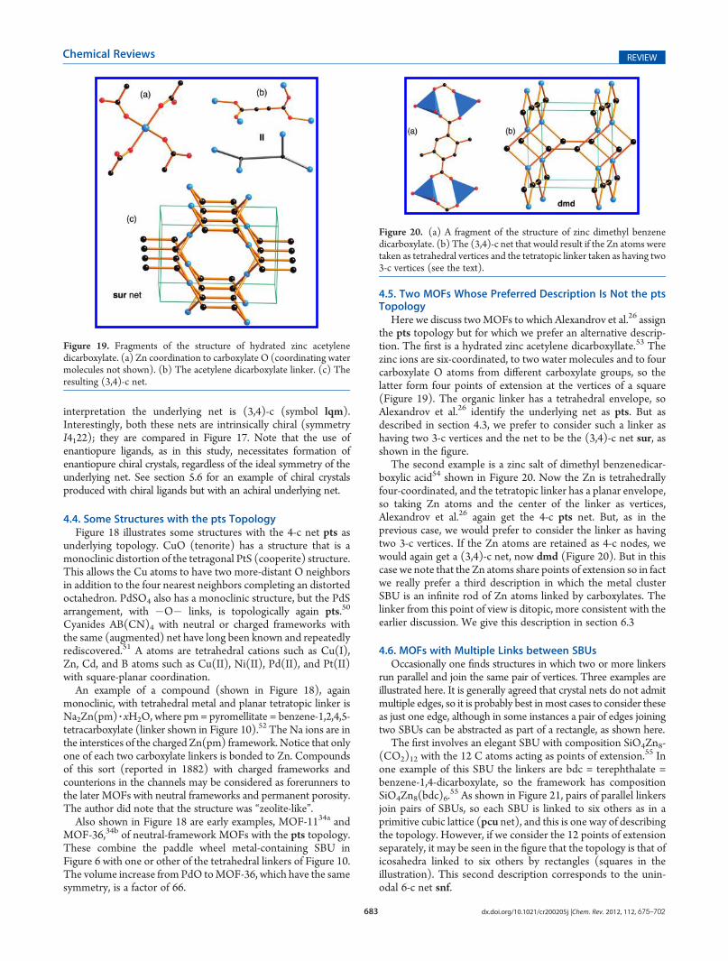
Here we discuss twoMOFs to which Alexandrov et al.26 assignthe pts topology but for which we prefer an alternative descrip-tion. The first is a hydrated zinc acetylene dicarboxyllate.53 Thezinc ions are six-coordinated, to two water molecules and to fourcarboxylate O atoms from different carboxylate groups, so thelatter form four points of extension at the vertices of a square(Figure 19). The organic linker has a tetrahedral envelope, soAlexandrov et al.26 identify the underlying net as pts. But asdescribed in section 4.3, we prefer to consider such a linker ashaving two 3-c vertices and the net to be the (3,4)-c net sur, asshown in the figure.
The second example is a zinc salt of dimethyl benzenedicar-boxylic acid54 shown in Figure 20. Now the Zn is tetrahedrallyfour-coordinated, and the tetratopic linker has a planar envelope,so taking Zn atoms and the center of the linker as vertices,Alexandrov et al.26 again get the 4-c pts net. But, as in theprevious case, we would prefer to consider the linker as havingtwo 3-c vertices. If the Zn atoms are retained as 4-c nodes, wewould again get a (3,4)-c net, now dmd (Figure 20). But in thiscase we note that the Zn atoms share points of extension so in factwe really prefer a third description in which the metal clusterSBU is an infinite rod of Zn atoms linked by carboxylates. Thelinker from this point of view is ditopic, more consistent with theearlier discussion. We give this description in section 6.3
4.6. MOFs with Multiple Links between SBUsOccasionally one finds structures in which two or more linkers
run parallel and join the same pair of vertices. Three examples areillustrated here. It is generally agreed that crystal nets do not admitmultiple edges, so it is probably best inmost cases to consider theseas just one edge, although in some instances a pair of edges joiningtwo SBUs can be abstracted as part of a rectangle, as shown here.
The first involves an elegant SBU with composition SiO4Zn8-(CO2)12 with the 12 C atoms acting as points of extension.55 Inone example of this SBU the linkers are bdc = terephthalate =benzene-1,4-dicarboxylate, so the framework has compositionSiO4Zn8(bdc)6.
55 As shown in Figure 21, pairs of parallel linkersjoin pairs of SBUs, so each SBU is linked to six others as in aprimitive cubic lattice (pcu net), and this is one way of describingthe topology. However, if we consider the 12 points of extensionseparately, it may be seen in the figure that the topology is that oficosahedra linked to six others by rectangles (squares in theillustration). This second description corresponds to the unin-odal 6-c net snf.
Figure 19. Fragments of the structure of hydrated zinc acetylenedicarboxylate. (a) Zn coordination to carboxylate O (coordinating watermolecules not shown). (b) The acetylene dicarboxylate linker. (c) Theresulting (3,4)-c net.
Figure 20. (a) A fragment of the structure of zinc dimethyl benzenedicarboxylate. (b) The (3,4)-c net that would result if the Zn atoms weretaken as tetrahedral vertices and the tetratopic linker taken as having two3-c vertices (see the text).

684 dx.doi.org/10.1021/cr200205j |Chem. Rev. 2012, 112, 675–702
Chemical Reviews REVIEW
The second example has a related structure. Now the metalcluster SBU with stoichiometry Zn7O4(CO2)10 has 10 points ofextension and is linked to six other SBUs—to four by doublelinks and to two by single links.56 Again the double links may beabstracted as rectangles and the net described as the 5-c net fqr,as shown in Figure 21.
A third example is a structure in which the metal-containingSBU consists of 11 Cd atoms and which has 18 points of
extension, again carboxylate C atoms, now of biphenyl dicarbo-xylate (bpdc).57 The Cd cluster, formed from 11 CdO6 octahe-dra, also contains formate (HCO2) groups that serve to hold thecluster together, and the framework is formulated as Cd11-(HCO2)6(bpdc)9. In this structure, each cluster is linked toeight neighboring clusters—to each of two by three bpdc linkersand to the other six by pairs of linkers (Figure 22). Consideringthe multiple links between a given pair of SBUs as one edge andthe clusters as 8-c vertices, the net is body-centered cubic (bcu).In this case, there is no obvious alternative description. Noticethat the cluster is chiral and has ideal symmetry 32 (D3); thecrystal symmetry is the achiral R3c, which means that clusters ofboth hands occur equally.
4.7. Examples of Lower-Symmetry Metal-Containing SBUsIt was remarked earlier that the augmented net derived from
an underlying net was not strictly defined in a mathematicalsense. For example, if one takes any polyhedron with eightvertices and links it to eight neighbors in the same waytopologically as in bcu (the net of the body-centered cubiclattice), the derived net will have bcu as its underlying net. This isillustrated in Figure 23 using the net bcu-i, in which squareantiprisms are linked in such a way. Clearly, the net is different(5-c, symmetry I422) from bcu-a (4-c, symmetry Im3m), but theunderlying net is the same.
Such examples are quite common in crystals. Figure 24 showsan example of an SBU that has points of extension at the verticesof a trigonal prism linked with the pcu topology by bent ditopiclinkers. The SBU is in fact the same as that shown in Figure 13and the authors correctly identified the underlying topology aspcu.46 The “augmented” 4-c net shown in Figure 24 has theRCSR symbol unp.
An example with a square antiprism replacing a cube is foundin the structure of a cyanide with framework composition Fe2-(H2O)4Mo(CN)8, with Fe bonded in a planar fashion to four
Figure 21. MOFs with multiple links between pairs of SBUs. (a) AnSBU linked to six others by pairs of links. (b) The net obtained if pairs oflinkers are considered sides of quadrangles. (c) An SBU linked to fourothers by pairs of links. (d) The net obtained if pairs of linkers areconsidered sides of quadrangles.
Figure 22. A MOF with an SBU with 18 points of extension andmultiple links between pairs of SBUs. Each SBU is linked to eight others.
Figure 23. Two nets with the same underlying topology (bcu).
Figure 24. A MOF with trigonal-prism SBUs linked with primitivecubic (pcu) topology: (a) a unit cell of the structure and (b) the trigonalprisms linked in pcu topology. The net of the vertices (red) is theuninodal 4-c unp.

685 dx.doi.org/10.1021/cr200205j |Chem. Rev. 2012, 112, 675–702
Chemical Reviews REVIEW
CN groups and with two water molecules completing an octa-hedron (Figure 25).58 The net of the linked antiprism and squareis a (3,5)-c net with RCSR symbol khn and symmetry I4/mcm.The underlying net is the (4,8)-c net scu, shown in its mostsymmetrical augmented form as linked squares and cubes in thefigure. It may be noted that the FeN4 “squares” in Figure 25 arenot strictly planar and might be construed as tetrahedra; theunderlying net would still be the same.
5. SOME CASE STUDIES
5.1. A MOF with ubt TopologyAnother example discussed by Alexandrov et al.26 is a crystal of
linked paddle wheels reported by Chun.59 In this material, thefour points of extension of the Zn2(CO2)4 paddle wheel arelinked to methyl isophthalic acid. One of the Zn atoms is alsoconnected to a ditopic dabco linker to make the unit a node of a5-c net. This is illustrated in Figure 26 (note that in this figure thestructure is somewhat simplified by omitting nonessential atomsfor clarity). Alexandrov et al. propose several different interpreta-tions of the topology. One considers the two Zn atoms of theSBU as separate 4-c and 5-c vertices of a net. But this is notconsistent with our general procedure which considers all metalatoms with common points of extension (carboxylate C atoms inthis case) as part of one cluster. A second possibility is to considerthe topology as simply defined by linked 5-c vertices, as shown inFigure 26. This is sufficient to define the topology completely asthe net is the uninodal net ubt (so named as it is the B net in UB12as Chun recognized).
However, there ismore to this structure. The 120� angle betweenthe carboxylates of the linker is just right to make a closedpolyhedron from 12 paddle wheel units. Such a supercluster isindeed found in the metal�organic polyhedron MOP-1.60 The
Figure 25. (a) The framework of a Fe, Mo cyanide with MoC8 squareantiprisms and FeN4 quadrangles (two water molecules coordinatingthe iron atoms not shown). (b) The net khn of the linked C and Natoms. (c) The net scu-a of the augmented scu net.
Figure 26. (a) Fragment of a MOF with Zn square paddle wheel SBUslinked by methyl isophthalic acid (methyl groups not shown in thefigure). (b) Twenty-four SBUs form MOP-1 clusters that are furtherlinked by dabco linkers (abstracted as linear ditopic linkers in thedrawing).

686 dx.doi.org/10.1021/cr200205j |Chem. Rev. 2012, 112, 675–702
Chemical Reviews REVIEW
12 outer Zn atoms of this supercluster are also joined to theditopic dabco linker so the MOP units are linked into a 12-c netwhich is in fact the net, fcu, of the face-centered cubic lattice(note that ubt can also be symbolized fcu-a), and Alexandrovet al. propose this as an alternative description of the underlyingnet. But this is not admitted here as the separate paddle wheels donot have common points of extension and should be consideredseparately. Interestingly, this structure was recently rediscoveredwith 4,40-bipyridine linking MOP-1 units, and this was describedas based on the fcu net.61
The net of the points of extension taken as separate vertices isthe augmented net ubt-a. This is illustrated in Figure 27 as the netof a tiling. In the figure the blue “MOP” units are in a face-centered cubic array and the green and yellow tiles correspondrespectively to the tetrahedral and octahedral holes of that lattice.We remark that the tiling is not natural in this case, as the squarepyramid tile has one face larger than the rest.13a
5.2. MOFs with Hexatopic Carboxylate LinkersA particularly interesting isoreticular series of MOFs has
emerged in the past few years, although there has been nogeneral agreement on the best description of the topology.The topology was first found independently and essentially
simultaneously by two groups.62 There have been several sub-sequent syntheses that have produced isoreticular materials,some with exceptional porosity.2a,63 The topology has beenidentified as the ubt structure described in section 5.1 and alsodescribed as the (3,24)-c net rht. A different assignment ismade here.
Figure 28 shows the linked metal-containing (Zn or Cucarboxylate paddle wheels) and organic SBUs for two com-pounds. Note that in one case the “organic” component isactually a hybrid metal�organic SBU.62a In each case, the centerof the unit is a 3-c branching point (vertex) of the net, and in eachcase the magenta spheres in the figure are also 3-c vertices. Thecenters of the paddle wheels are, as usual, 4-c vertices. Theresulting net, RCSR symbol ntt, is a trinodal (3,4)-c net. Notethat, as in the previous section, the paddle wheels are again linkedby metadicarboxylate units and the structure again contains theMOP-1 cluster of 12 paddle wheels (Figure 29). Now, however,these units are joined by links to the 24 edges of that cluster,hence having the alternative description of a (3,24)-c underlyingnet (RCSR symbol rht).
If the arms of the linker are made shorter, it is no longerpossible for the links to 3-c vertices in a given SBU to be allplanar. Then another trinodal (3,4)-c net, symbol zyg, is found.64
Interestingly, this net, like ntt, has the minimum number, two, ofdifferent kinds of edge (Figure 29); in the jargon the nets areedge two-transitive. The linker is the same as the one shown inFigure 31 below.
Yet another point of interest about the ntt topology is whathappens if one considers the hexatopic organic unit to be just onehexagonal 6-c vertex in the same way as suggested by Alexandrovet al.26 for the tetratopic SBU in Figure 11 (section 4.3). Thenone obtains an edge-transitive (4,6)-c net. This net is not in ourcompilation of such nets13e,14 for the following reason. As may beseen from Figure 30, pairs of 4-c vertices have the same set of fourneighbors. As a consequence, in barycentric (center-of-mass)coordinates the 4-c vertices collide in pairs. More importantly,such a graph has “non-rigid body” symmetries; thus, interchan-ging a pair of vertices with common neighbors while the rest iskept unchanged is a symmetry (automorphism) of the graph.Such an operation cannot correspond to a rigid body symmetryoperation and the automorphism group of the net does notcorrespond to a crystallographic symmetry group. For thisreason, such nets are often called “noncrystallographic”.65 Thereis no compelling reason to avoid such nets, but when possible, an
Figure 27. The augmented ubt net as a tiling. In the lower half, the tilesare slightly shrunk to leave gaps between them. Red tiles are squarepyramids.
Figure 28. (a) A hexatopic linker joined to paddle wheel SBUs. Blueshapes are Zn�O (left) coordination polyhedra. Large green andmagenta spheres mark 3-c vertices of the net. (b) Another hexatopiclinker now linked to Cu paddle wheels. The light blue shapes areCuN2O3 trigonal prisms. The central O atom is a 3-c vertex correspond-ing to the green sphere in part a.

687 dx.doi.org/10.1021/cr200205j |Chem. Rev. 2012, 112, 675–702
Chemical Reviews REVIEW
alternative topological description is preferred when they arise.More to the point perhaps is that the net in Figure 30 does notreally reflect the nature of the parent structures.
The corresponding edge-transitive (4,6)-c net derived fromzyg is the binodal edge-transitive net stp.
The small tetratopic linker that led with paddle wheels to thezyg topology has also been linked to the octahedral basic zincacetate SBU, as shown in Figure 31.66 Now one gets a trinodal(3,6)-c net zxc shown in augmented form in Figure 32. Thisnet also has the minimum number of kinds of edge, emphasizingagain that the most simple possibility is often what is obtained inpractice. Interestingly, when the linker is expanded, as shown inFigure 31, the same topology is found with the same Zn SBU.67 Itwould be interesting to see if further isoreticular compoundscould be made using some of the other linkers of this section.
It should be apparent from Figure 31 that the envelope of theorganic linker is an octahedron, and if this were adopted as a basicunit, then the underlying net would be 6-c with octahedral metalSBUs joined by octahedral linkers. In fact, it has the topology of abinary version of the primitive cubic net pcu as in NaCl, and this
Figure 30. A net with noncrystallographic symmetries. Notice that theblack links join each of a pair of blue vertices to the same set of four greenvertices.
Figure 29. Augmented versions of two trinodal (3,4)-c nets discussedin the text.
Figure 31. Units of the structures of two MOFs: (a) ref 66 and (b) ref67. In both cases, 3-c vertices (branching points) are shown as largemagenta spheres and 6-c vertices are at the center of the cluster of fourZnO4 tetrahedra (blue).
Figure 32. The (3,6)-c net zxc shown in augmented form (zxc-a) aslinked triangles and octahedra.
688 dx.doi.org/10.1021/cr200205j |Chem. Rev. 2012, 112, 675–702
Chemical Reviews REVIEW
description was preferred by both sets of authors.66,67 But,although informative, this does not explain the far from cubicmetrics of the crystal structures.
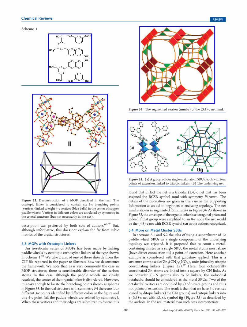
5.3. MOFs with Octatopic LinkersAn isoreticular series of MOFs has been made by linking
paddle wheels by octatopic carboxylate linkers of the type shownin Scheme 1.68 We take a unit of one of these directly from theCIF file reported in the paper to illustrate how we deconstructthe framework. We note that, as is very commonly the case inMOF structures, there is considerable disorder of the carbonatoms. In this case, although the paddle wheels are clearlyresolved, the center of the organic linker is disordered. However,it is easy enough to locate the branching points shown as spheresin Figure 33. In the real structure with symmetry P4 there are fourdifferent 3-c points identified by different colors in the figure andone 4-c point (all the paddle wheels are related by symmetry).When these vertices and their edges are submitted to Systre, it is
found that in fact the net is a trinodal (3,4)-c net that has beenassigned the RCSR symbol mml with symmetry P4/nmm. Thedetails of the calculation are given in this case in the SupportingInformation as an aid to beginners at analyzing topology. The netmml is shown in augmented formmml-a in Figure 34. As shown inFigure 33, the envelope of the organic linker is a tetragonal prism andindeed if that group were simplified to an 8-c node the net wouldbe the (4,8)-c net with RCSR symbol scu as the authors recognized.
5.4. More on Metal Cluster SBUsIn sections 5.1 and 5.2 the idea of using a supercluster of 12
paddle wheel SBUs as a single component of the underlyingtopology was rejected. It is proposed that to count a metal-containing cluster as a single SBU, the metal atoms must share(have direct connection to) a point of extension. Here anotherexample is considered with that guideline applied. This is astructure composed of Zn4(CN)4(NO3)4 units joined by tritopiccoordinating linkers (Figure 35).69 Here, four octahedrallycoordinated Zn atoms are linked into a square by CN links. Aswe consider C�N groups also to be linkers, the individualoctahedra should be considered as the metal SBUs. Two of theoctahedral vertices are occupied by O of nitrate groups and thusnot points of extension. The result is then that we have 4-c verticesjoined by ditopic linkers (the CN groups) and tritopic linkers intoa (3,4)-c net with RCSR symbol tfg (Figure 35) as described bythe authors. In the real material two such nets interpenetrate.
Scheme 1
Figure 33. Deconstruction of a MOF described in the text. Theoctatopic linker is considered to contain six 3-c branching points(vertices) linked to eight 4-c vertices (blue balls) in the center of copperpaddle wheels. Vertices in different colors are unrelated by symmetry inthe crystal structure (but not necessarily in the net).
Figure 34. The augmented version (mml-a) of the (3,4)-c net mml.
Figure 35. (a) A group of four single-metal-atom SBUs, each with fourpoints of extension, linked to tritopic linkers. (b) The underlying net.
689 dx.doi.org/10.1021/cr200205j |Chem. Rev. 2012, 112, 675–702
Chemical Reviews REVIEW
Two examples of a 9-c SBU were reported at the same time.70
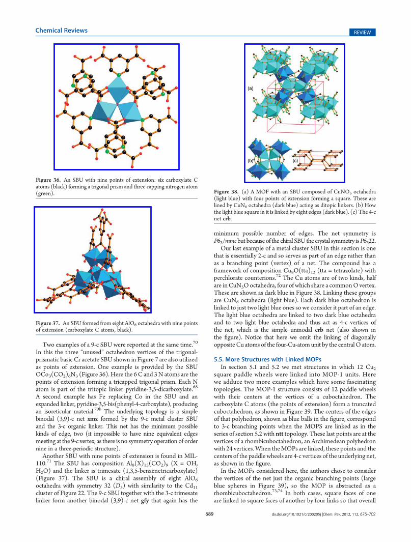
In this the three “unused” octahedron vertices of the trigonal-prismatic basic Cr acetate SBU shown in Figure 7 are also utilizedas points of extension. One example is provided by the SBUOCo3(CO2)6N3 (Figure 36). Here the 6 C and 3N atoms are thepoints of extension forming a tricapped trigonal prism. Each Natom is part of the tritopic linker pyridine-3,5-dicarboxylate.68
A second example has Fe replacing Co in the SBU and anexpanded linker, pyridine-3,5-bis(phenyl-4-carboxylate), producingan isoreticular material.70b The underlying topology is a simplebinodal (3,9)-c net xmz formed by the 9-c metal cluster SBUand the 3-c organic linker. This net has the minimum possiblekinds of edge, two (it impossible to have nine equivalent edgesmeeting at the 9-c vertex, as there is no symmetry operation of ordernine in a three-periodic structure).
Another SBU with nine points of extension is found in MIL-110.71 The SBU has composition Al8(X)15(CO2)9 (X = OH,H2O) and the linker is trimesate (1,3,5-benzenetricarboxylate)(Figure 37). The SBU is a chiral assembly of eight AlO6
octahedra with symmetry 32 (D3) with similarity to the Cd11cluster of Figure 22. The 9-c SBU together with the 3-c trimesatelinker form another binodal (3,9)-c net gfy that again has the
minimum possible number of edges. The net symmetry isP63/mmcbut because of the chiral SBU the crystal symmetry isP6322.
Our last example of a metal cluster SBU in this section is onethat is essentially 2-c and so serves as part of an edge rather thanas a branching point (vertex) of a net. The compound has aframework of composition Cu8O(tta)12 (tta = tetrazolate) withperchlorate counterions.72 The Cu atoms are of two kinds, halfare inCuN5Ooctahedra, four of which share a commonO vertex.These are shown as dark blue in Figure 38. Linking these groupsare CuN6 octahedra (light blue). Each dark blue octahedron islinked to just two light blue ones so we consider it part of an edge.The light blue octahedra are linked to two dark blue octahedraand to two light blue octahedra and thus act as 4-c vertices ofthe net, which is the simple uninodal crb net (also shown inthe figure). Notice that here we omit the linking of diagonallyopposite Cu atoms of the four-Cu-atom unit by the central O atom.
5.5. More Structures with Linked MOPsIn section 5.1 and 5.2 we met structures in which 12 Cu2
square paddle wheels were linked into MOP-1 units. Herewe adduce two more examples which have some fascinatingtopologies. The MOP-1 structure consists of 12 paddle wheelswith their centers at the vertices of a cuboctahedron. Thecarboxylate C atoms (the points of extension) form a truncatedcuboctahedron, as shown in Figure 39. The centers of the edgesof that polyhedron, shown as blue balls in the figure, correspondto 3-c branching points when the MOPS are linked as in theseries of section 5.2 with ntt topology. These last points are at thevertices of a rhombicuboctahedron, an Archimedean polyhedronwith 24 vertices.When theMOPs are linked, these points and thecenters of the paddle wheels are 4-c vertices of the underlying net,as shown in the figure.
In the MOFs considered here, the authors chose to considerthe vertices of the net just the organic branching points (largeblue spheres in Figure 39), so the MOP is abstracted as arhombicuboctahedron.73,74 In both cases, square faces of oneare linked to square faces of another by four links so that overall
Figure 37. An SBU formed from eight AlO6 octahedra with nine pointsof extension (carboxylate C atoms, black).
Figure 38. (a) A MOF with an SBU composed of CuNO5 octahedra(light blue) with four points of extension forming a square. These arelined by CuN6 octahedra (dark blue) acting as ditopic linkers. (b) Howthe light blue square in it is linked by eight edges (dark blue). (c) The 4-cnet crb.
Figure 36. An SBU with nine points of extension: six carboxylate Catoms (black) forming a trigonal prism and three capping nitrogen atom(green).

690 dx.doi.org/10.1021/cr200205j |Chem. Rev. 2012, 112, 675–702
Chemical Reviews REVIEW
each MOP is connected to six others, as shown in Figure 40. Thearray of MOPs form a primitive cubic array. The most symmetricway to do this results in a uninodal 5-c net, pcu-i, of cubicsymmetry.73 In the other structure the net of organic branchingpoints,mjz, is binodal and has tetragonal symmetry, as shown inthe figure.73 These two nets are generated by linking rhombicu-boctahedra by cubes. We can also consider the nets as a tilingof a 3-periodic surface by polygons (“infinite polyhedra” orapeirohedra) with one triangle and four squares meeting at everyvertex, so the two-dimensional vertex symbol is 3.44 in bothcases. Note we use a vertex symbol appropriate for a two-dimensional tiling of the infinite surface; for the three-dimensional5-c net, the vertex symbol for pcu-i is 3.4.4.4.4.8.8.8.8, indicatingthat there are eight rings in the net. Readers unfamiliar with vertexsymbols are referred to a recent review.24
However, the description in the previous paragraph is insuffi-cient to fully describe the topology of these structures. In theMOP rhombicuboctahedron, there are two kinds of square, say Aand B. One, say A, contains the 4-c net vertex and the other doesnot. In the structures described above the first has, per MOP, oneAA and two BB links between MOPs. The resulting (4,5)-c net isassigned the RCSR symbol zmj. We believe this best describes theunderlying topology of the MOF. The second structure has one
AB and twoBB links. The corresponding (4,5)-c net, zhc, has eightdifferent kind of vertex. These two nets are illustrated in Figure 41.Clearly, there is a multitude of possibilities. The simplest, ucp,derived from all AA links betweenMOPs is a binodal (3,4)-c net. Itis also shown in the figure. We have not yet found it in a MOF.
Figure 39. Three aspects of the MOP-1 topology. (a) Twelve linkedsquares with blue balls marking the points of extension when MOPs arelinked into frameworks. (b) The pattern (a rhombicuboctahedron) ofjust those points of extension. (c) The pattern of 4- and 3-c vertices in alinked framework.
Figure 40. (a and b) Structures formed by linking MOPS to six others.(c and d) The nets produced by just the points of extension (blue inFigure 39 in parts a and b, respectively). The nets of the structures aremjz (c) and pcu-i (d).
Figure 41. (a) The (3.4)-c net of theMOF in Figure 40a. (b) The (3.4)-c net of the MOF in Figure 40b. (c) The simplest binodal (3,4)-c net ofthis type.

691 dx.doi.org/10.1021/cr200205j |Chem. Rev. 2012, 112, 675–702
Chemical Reviews REVIEW
5.6. A Cyclodextrin MOFHere we discuss aMOF formed by coordination of alkali metal
ions by γ-cyclodextrin (CD), a symmetrical cyclic oligosacchar-ide consisting of a ring of eight C6 monosaccharide units that isreadily available in large quantities.75 The resultingmaterial (CD-MOF) which is built of enantiopure chiral organic componentsforms a cubic structure with chiral symmetry I432. We seethough that the underlying net is achiral, symmetry Im3m.
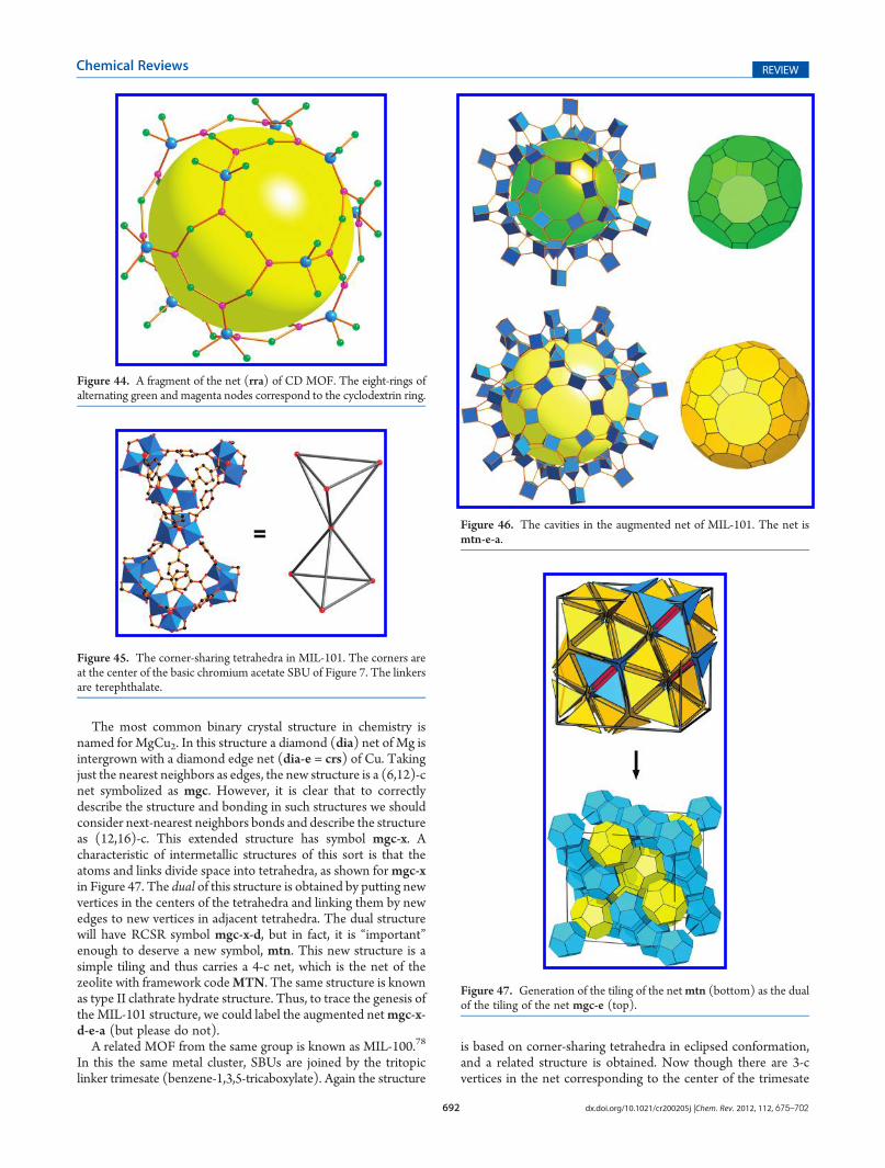
Figure 42 shows a cyclodextrin unit from the crystal structure,first alone and then with neighboring KO8 polyhedra. Each K isconnected to four different rings and so is a 4-c vertex of theunderlying net. Each cyclodextrin ring consists of eight C5O rings,and the centers of these, which are of two kinds, are identified as3-c vertices, as shown in Figure 43. A fragment of the (3,4)-c netsrra is shown in Figure 44. It may be seen that six eight-memberedcyclodextrin rings (3-c green and magenta vertices) are linked by4-c vertices (large blue balls) around a large central cavity. Theseare joined in turn in a body-centered cubic array.75
Further details of the analysis of this structure are provided inthe Supporting Information.
5.7. The Hierarchical Underlying Nets of MIL-101 andMIL-100MIL-101 is a complex MOF built from two simple compo-
nents that are the trigonal prismatic basic chromium acetate SBU(Figure 7) and the ditopic terephthalate linker.76 As may be seenfrom the fragment of the structure shown in Figure 45, thecenters of the metal cluster SBUs are linked into corner-sharingtetrahedra to form a 6-c net. It is straightforward to identify all thecrystallographically distinct SBUs (there are four) and to identifytheir neighbors. It will then be found that the net has the RCSRsymbol mtn-e. This is a quadrinodal 6-c net (transitivity 4795)that at first sight seems surprisingly complicated to serve as thenet of a MOF formed from two simple components. However, itturns out that the geometric requirement of linking TX4 tetra-hedra with T�X�T angles of 180� and with eclipsed conforma-tion as shown in Figure 41 leads inexorably to mtn-e as theoptimum structure, a very nice example of how a simple localgeometric restriction can lead to a complex periodic structure.77
Note that the eclipsed conformation is a natural consequence ofthe trigonal-prismatic shape of the SBU; an octahedral SBUwould lead to staggered tetrahedra.77
If we consider the points of extension of the metal clusterSBUs in MIL-101 as vertices, then we have a 4-c net of linkedtrigonal prisms with symbol mtn-e-a. Aspects of this net are
shown in Figure 46. It is the net of a simple tiling by trigonalprisms, truncated tetrahedra, and two large polyhedra. Thesmaller of these last is the Archimedean polyhedron, known asthe truncated icosidodecahedron, which has 120 vertices withvertex symbol 4.6.10. The other polyhedron is larger and hastwo kinds of vertex, 120 with symbol 4.6.10 and 48 withsymbol 4.6.12.
It is of interest to consider progenitors of the net. They arestructures that should be in every chemistry textbook, but un-fortunately, as of yet, generally they are not.
Figure 42. (a) A cyclodextrin unit from the CD-MOF. (b) The samewith linked KO8 polyhedra.
Figure 43. The three topologically distinct vertices in the CD-MOFshown as large spheres. The magenta and green are 3-c and the blue(metal atom site) is 4-c.
692 dx.doi.org/10.1021/cr200205j |Chem. Rev. 2012, 112, 675–702
Chemical Reviews REVIEW
The most common binary crystal structure in chemistry isnamed for MgCu2. In this structure a diamond (dia) net of Mg isintergrown with a diamond edge net (dia-e = crs) of Cu. Takingjust the nearest neighbors as edges, the new structure is a (6,12)-cnet symbolized as mgc. However, it is clear that to correctlydescribe the structure and bonding in such structures we shouldconsider next-nearest neighbors bonds and describe the structureas (12,16)-c. This extended structure has symbol mgc-x. Acharacteristic of intermetallic structures of this sort is that theatoms and links divide space into tetrahedra, as shown formgc-xin Figure 47. The dual of this structure is obtained by putting newvertices in the centers of the tetrahedra and linking them by newedges to new vertices in adjacent tetrahedra. The dual structurewill have RCSR symbol mgc-x-d, but in fact, it is “important”enough to deserve a new symbol, mtn. This new structure is asimple tiling and thus carries a 4-c net, which is the net of thezeolite with framework codeMTN. The same structure is knownas type II clathrate hydrate structure. Thus, to trace the genesis ofthe MIL-101 structure, we could label the augmented netmgc-x-d-e-a (but please do not).
A related MOF from the same group is known as MIL-100.78
In this the same metal cluster, SBUs are joined by the tritopiclinker trimesate (benzene-1,3,5-tricaboxylate). Again the structure
is based on corner-sharing tetrahedra in eclipsed conformation,and a related structure is obtained. Now though there are 3-cvertices in the net corresponding to the center of the trimesate
Figure 44. A fragment of the net (rra) of CD MOF. The eight-rings ofalternating green and magenta nodes correspond to the cyclodextrin ring.
Figure 45. The corner-sharing tetrahedra in MIL-101. The corners areat the center of the basic chromium acetate SBU of Figure 7. The linkersare terephthalate.
Figure 46. The cavities in the augmented net of MIL-101. The net ismtn-e-a.
Figure 47. Generation of the tiling of the netmtn (bottom) as the dualof the tiling of the net mgc-e (top).

693 dx.doi.org/10.1021/cr200205j |Chem. Rev. 2012, 112, 675–702
Chemical Reviews REVIEW
six-membered ring and a (3,6) net, the RCSR symbol moo isgenerated (Figure 48). Fragments of the corresponding augmentednet of linked triangles and trigonal prisms are shown in Figure 49.
A spectacular isoreticular material meso-MOF-1 with Tb inthe trigonal prismatic SBU and triazine-1,3,5-tribenzoate aslinker has since been reported.79 This material has a face-centered cubic unit cell edge of 123.9 Å and cage diameters of3.9 and 4.7 nm. Note that in all these materials the arrangementof the two large cages is that of Mg and Cu in MgCu2.
6. MOFS WITH ROD SBUS
Rod MOFs contain infinite 1-periodic SBUs (rods).80 Theyare of interest as they usually have parallel channels and oftenexhibit pronounced “breathing”, in which the rods act ashinges.81 Recall that for finite metal-containing SBUs wegenerally could identify k points of extension that defined apolygon or polyhedron with k vertices in the center of which werecognize a k-c vertex of a net. Such a procedure is hard to adaptto rod SBUs. In some instances, we can associate the points ofextension with a rodlike structure, such as a ladder, but in otherinstances, the reduction to a net is a little more arbitrary and wethen proceed on an ad hoc basis, but treating the organic linkersin the same way as before. The difficulty is even more pro-nounced for MOFs in which metal atoms sharing points ofextension are in continuous two-periodic layers; these occurrather rarely.
6.1. SBUs as Zigzag LaddersA versatile and often-studied group of MOF structures is
variously known as MIL-47/MIL-53/MIL-6082 and MOF-71.80
The metal SBU consists of a rod of MO6 octahedra sharingopposite corners and with stoichiometry MX(CO2)2, X = O orOH and M = Al, Cr, Co, Fe, Ga, or V. Figure 50 illustrates MOF-71, basic vanadium terephthalate with framework VO(bdc)2(bdc = benzene-1,4-dicarboxylate). The figure also depicts onerod showing that the points of extension (the carboxylate Catoms) fall on a zigzag ladder (often called a “double zig-zag”).
Figure 48. A fragment of the structure of MIL-100. Green balls are 3-cnodes of the underlying net (moo). 6-c nodes are at the center of theblue SBU. On the right, the red lines outline the tetrahedra.
Figure 49. Fragments of the netmoo-a as linked triangles and trigonalprisms and showing the two large cavities (yellow and green balls).
Figure 50. Aspects of the structure of MOF-71. (a) View along the roddirection showing how the rods are linked. (b) One rod with the pointsof extension (carboxylate C atoms) linked into a zigzag ladder.

694 dx.doi.org/10.1021/cr200205j |Chem. Rev. 2012, 112, 675–702
Chemical Reviews REVIEW
These are linked by ditopic linkers to form the uninodal 4-c netsra illustrated in Figure 51.
Another MOF with the same underlying net is MOF-69.83
The rods now consist of metal�oxygen octahedra and tetrahe-dra, as shown in Figure 52, but the points of extension again formzigzag ladders linked as in sra.
Yet another rodlike SBU with points of extension formingzigzag ladders is also shown in Figure 52.84 In this last case, linksbetween the ladders are via the imidazole ring part of hypo-xanthine, and as the authors noted, the ladders are now linked in adifferent way, that of the net umr (Figure 51). This net and twoother uninodal ways (atn and umu) of linking zigzag ladders(Figure 51) were overlooked in our earlier account of uninodalnets for linking rodlike SBUs.80 Although at first glance umr andumu look very similar, they actually have different symmetries(I41/acd and I41/amd, respectively).
6.2. A MOF with a Twisted Ladder Rod SBUIn MOF-75, rods of linked TbO8 dodecahedra are linked by
the ditopic linker 2,5-thiophene dicarboxylate.80 Figure 53ashows two rods and one linker. In the crystal there are two kindsof carboxylate carbons, the points of extension. These form aladder along the rod, as shown in the figure. Figure 53b showsthat the ladder is now twisted compared to the zigzag ladders ofthe previous sections. When the connectivity of the two verticesis submitted to Systre, it is found that topologically the net is theuninodal irl illustrated in Figure 53c. Other uninodal ways oflinking twisted ladders are uoa and uoe (see the RCSR database).
Figure 51. Four ways of linking zigzag ladders into uninodal 4-c nets.
Figure 52. Two rods with points of extension forming a zigzag ladder.(a) In MOF-69, the points of extension are carboxylate C atoms and(b) a rod SBU reported by Zhang et al.80 The linker has three N atoms(green) but only two (larger spheres) are considered as nodes of theunderlying net.
Figure 53. Aspects of the structure of MOF-75. (a) Two rod SBUsconnected by a linker (yellow sphere is an S atom). The carboxylate Catoms forming the points of extension are of two crystallographic kindsin the crystal. These are shown as magenta and green on the fragment ofthe net on the right. (b) Left: one rod showing that the points ofextension form a twisted ladder. Right: the underlying net irl.
Figure 54. (a) The structure of the points of extension of the MOF inFigure 20 interpreted as a rod of edge-sharing tetrahedra. (b) The net ofthese rods linked by ditopic linkers.

695 dx.doi.org/10.1021/cr200205j |Chem. Rev. 2012, 112, 675–702
Chemical Reviews REVIEW
6.3. A MOF with Rod SBUs of Linked TetrahedraWe remarked in section 4.5 that the MOF (Figure 20) whose
topology had been described as ptswas better considered as a rodMOF with the rods linked by ditopic linkers. Figure 54 displaysone rod of the structure showing that the points of extension(carboxylate carbons) form a rod of tetrahedra sharing oppositeedges. Linking these by edges corresponding to the ditopiclinkers produces the uninodal 6-c net snp, also shown in thefigure.
6.4. Two-Way Rod SBUs of Linked TetrahedraIn MOF-7780 the rod SBUs consist of ZnO4 tetrahedra linked
by carboxylates, and the points of extension form a rod of edge-sharing tetrahedra in exactly the same way as shown in Figure 54.The organic linker is the tetratopic 1,3,5,7-adamantanetetracar-boxlate (see Figure 10), the center of which is a 4-c vertex of theunderlying net. The other vertices of the net are the carboxylates
which are joined to five other carboxylates and to the 4-c vertex toform the (4,6)-c net mss shown in Figure 55.
A variation on this theme is a MOF containing rods of linkedZnN4 tetrahedra joined by a tritopic pyrazole-based linker shownin Figure 56.85 In the figure, a 3-c node of the underlying net isshown as magenta and C atom points of extension of the rod areshown as larger black spheres. Again the points of extension formrods of edge-sharing tetrahedra, as shown in Figure 57. These arelinked now by 3-c vertices to form the (3,6)-c net cgc shown inFigure 53.
These structures provide rare examples of rod MOFs with rodaxes in two different directions. Note that in the first structure therods form a four-layer sequence along the axis normal to those ofthe rods. In the second case, it is a two-layer sequence. These arerespectively patterns 5 and 6 in our review of rod packings inMOFs.80
6.5. MOFs with Rod SBUs of Linked OctahedraA structure discussed by Alexandrov et al.26 (identified by
them as CDC code AFOYOK) consists of CuN6 octahedralinked by triazole/tetrazole linkers.64 A rod from the structure isshown in Figure 58. The net was identified as a binodal (4,6)-cnet with vertices corresponding to the Cu atoms, and the centerof the linkers are considered as tetratopic. However, as discussedin a similar case in section 6.3, we consider the Cu octahedra toshare points of extension with their neighbors and thus form aninfinite rod SBU. The points of extension are the C atoms of thefive-membered rings that are shown as larger spheres in thefigure. These points of extension form a rod of octahedra linkedby sharing opposite faces as also shown in the figure. Finally,linking these rods produces the binodal 7-c net oab alsoillustrated in the figure.
A related structure is found in Sc(bdc)3 (bdc =1,4-benzenedi-carboxylate = terephthalate) with Sc in octahedral coordination.87
Again, there are rods of octahedra now sharing carboxylate Catoms as points of extension, and these points of extension formrods of face-sharing octahedra (Figure 59). The linking of theserods gives the binodal 7-c net sct (Figure 60). There is a closelyrelated uninodal 7-c net wnf again constructed by linking rods offace-sharing octahedra (Figure 60), and it is natural to ask why thelower-symmetry (Fddd) binodal topology is adopted rather thanthemore symmetrical (R3m) uninodal one. The answer appears tobe that the latter has two kinds of octahedron; compare just one
Figure 55. Two nets formed by linking rods of edge-sharing tetrahedra.
Figure 56. A tritopic pyrazole-based linker with a 3-c vertex shown inmagenta. The large black spheres are the C atom points of extension ofrod SBUs.
Figure 57. (a) A rod of linked ZnN4 tetrahedra. (b) The same showingthe mode of linking to the linker of Figure 56. (c) The nodes of theunderlying net.

696 dx.doi.org/10.1021/cr200205j |Chem. Rev. 2012, 112, 675–702
Chemical Reviews REVIEW
kind in the former. Applied to the real structure the chosenstructure is that with just one kind of Sc atom (Sc atoms centerthe octahedra of the underlying net).
An interesting alternative deconstruction of the Sc(bdc)3structure has also been suggested.88 In this approach, verticesare placed in the centers of the octahedron faces normal to therod axis. These vertices are linked to three others on adjacentrods and to two on the same rod) one above and one below).One then gets the uninodal 5-c net ghw. This is an attractivesimplification, but it obscures the shape of the rod SBU.
6.6. Rod SBUs That Resist SimplificationNot all rod SBUs have points of extension that form a simple
envelope such as a ladder or rods of linked polyhedra in theprevious examples. For these it seems that the best strategy fordescribing the topology is to include the individual metal atoms
Figure 58. (a) A rod of CuN6 octahedra (N atoms green) linked byditopic linkers. The points of extension are C atoms shown as large blackspheres. (b) The SBU of face-sharing octahedra formed by these pointsof extension. (c) The underlying 7-c net oab.
Figure 59. A rod in the structure of Sc(bdc)3. (a) A rod with carboxylateC atoms (points of extension) as large black spheres. (b) The same withpoints of extension linked by edges. (c) Just the linked points of extension.
Figure 60. Two ways of linking rods of face-sharing octahedra. (a) Thebinodal net sct that is the underlying net of Sc(bdc)3. (b) The uninodalnet wnf. This net has two kinds of octahedra, shown as dark andlight blue.
Figure 61. (a) A fragment of the structure of MOF-76. The magentaball marks a 3-c vertex linked to carboxylate C atoms (large black ball).(b) Showing the 3-c vertices of the underlying net. (c) Showing that theblue vertices are 6-c.

697 dx.doi.org/10.1021/cr200205j |Chem. Rev. 2012, 112, 675–702
Chemical Reviews REVIEW
as vertices. Note that this is not what we have done for any of thefinite-cluster metal-containing SBUs in any of the above exam-ples. To illustrate this point, we use the structure of MOF-76,80
one which has attracted some subsequent attention.89 In thismaterial, TbO7 polyhedra are joined by carboxylate links intorods with a rather irregular array of points of extension. Thecarboxylate linker is the tritopic 1,3,5-benzenetricarboxylate. Afragment of the structure is shown in Figure 61. As shown in thefigure, we take the center of the organic linker to be a 3-c vertexlinked to three carboxylate C vertices that are in turn linked alsoto two metal atoms, so these are also 3-c vertices. Notice thatthese are of two different kinds. Finally, the metal atoms arelinked to six carboxylate vertices, so the net is (3,6)-c. This net,which is intrinsically chiral (space group P4322), has RCSRsymbol rnb and is illustrated in Figure 62. It is rather complex,but one must sometimes just take what one gets.
A recently published related chiral rod structure again withatoms joined by a tricarboxylate linker has some similarities, butreference to Figure 63 shows an additional complication.90 Twoof the carboxylates are joined to two different metal atoms, andthe C atoms are considered as branch points; however, the thirdcarboxylate is linked to just one metal atom, so there is not anassociated branch point. Again, the net (Figure 63) is rathercomplicated for such simple components and has low symmetry(P43). It is assigned the RCSR code rnc.
A final example of a rod SBU is that found in MOF-74,80
a structure that has attracted some attention recently as themagnesium analog.91 In this material, rods of edge-sharing ZnO6
octahedra are joined by 2,5-dihydroxy-1,4-benzenedicarboxylicacid, as shown in Figure 64. Each rod, which taken alone is chiral,is linked to three others of opposite hand. The rod is verycondensed; each linker joins four octahedra on one rod to fouron another. Each carboxylate is linked to three Zn octahedra, andthe hydroxy O is linked to two Zn octahedra. Identifying all thebranching points would result in a net of such complexity that itwould lead to little insight into the underlying topology.
A possible strategy is to replace the linker by an 8-c vertexlinked to four metal atoms on each rod. The metal atoms in turnserve as 4-c vertices, and a (4,8)-c net results. This is, in fact, thesolution adopted by Alexandrov et al.36 However, we do notadopt this approach; the net does not contain any links along therod itself, and it is hard to justify finding a point on the linker as an8-c vertex.
Accordingly, in this case we resort to the simplification shownin Figure 65. In the simplified net, vertices are placed in the centerof the group of four octahedra linked by each linker (large greenballs in the figure), and a single edge links these vertices to one onan adjacent rod. In a way, we have broken the rod into a sequenceof subunits lined along the rod. The resulting net (Figure 66) isthe uninodal 3-c net with symbol etb, one of the two ways oflinking 3-fold helices, which now represent the rod SBUs, intouninodal nets (the other possibility is eta).80
Figure 62. The net rnb of MOF-76. Blue vertices are the 6-c vertices.
Figure 63. (a) A fragment of a rod net reported by Guo et al.90 This isdeconstructed in the same way as MOF-76 (see Figure 61). (b) Theunderlying (3,6)-c net rnc (compare Figure 62).
Figure 64. Fragments of the structure of MOF-74. (a) One linkerjoining two rods. (b) The pattern of linkers from one rod.
Figure 65. Deconstruction of MOF-74. Each end of the linker isjoined to four metal-atom polyhedra replaced by a large green ball.These are shown (a) only for the linkers shown (which are in the planeof the drawing). (b) All the green balls, which are 3-c vertices,are shown.

698 dx.doi.org/10.1021/cr200205j |Chem. Rev. 2012, 112, 675–702
Chemical Reviews REVIEW
7. MOFS WITH RING SBUS
MOFs with cation coordination polyhedra that form rings areso far relatively rare. Here we consider just two examples fromthe recent literature.
The first example is a basic titanium terephthalate, in which eightTiO6 octahedra are joined in a ring by edge and vertex sharing, and
the rings are linked by terephthalate.92 Each ring has 12 points ofextension, as shown in Figure 67, and is linked to 12 others by theterephthalate linkers to form a (4,5) binodal net mdh.
The topology of the linkage between rings is the 12-c net fcu ofthe face-centered cubic lattice, and one might consider the net asan augmented form of fcu, as the authors suggest. However, thering SBU has a very different shape from a cuboctahedron, whichis the most regular vertex figure of fcu, so we prefer to considerthe topology as described by the new net mdh.
Ourfinal example is aMOFwith ringsof 12BeO4 tetrahedra linkedby corner-sharing reported by Sumida et al.93 The points of extensionare carboxylateC atoms of 1,3,5-benzenetribenzoate. The 12 points ofextension form a puckered ring with 2-c and 3-c vertices, as shown inFigure 68. Combining thesewith the 3-c vertices of the linker gives the(3,4)-c net sum with symmetry P42/nmc illustrated in Figure 69.
7.1. CodaReaders who have read through this long paper deserve a
finishing treat, and here it is, at least for those who love nets: If weinstead considered the points of extension of the Be SBU in theprevious paragraph as forming a ring of all 2-c vertices, as shownin Figure 68, then the net obtained by combining with the
Figure 66. The 3-c net etb. Each helix is bonded to others of opposite hand.
Figure 67. (a) ring SBU of eight TiO6 octahedra and the pattern of thepoints of extension. (b) The (5.4)-c net obtained by linking each SBU to12 neighbors.
Figure 68. (a and b) An SBU formed of 12 BeO4 tetrahedra. (c and d)Two ways of linking the points of extension.
Figure 69. Two nets formed by linking the 12-ring SBU corresponding tothe two ways of linking the points of extension in Figure 68(see the text).
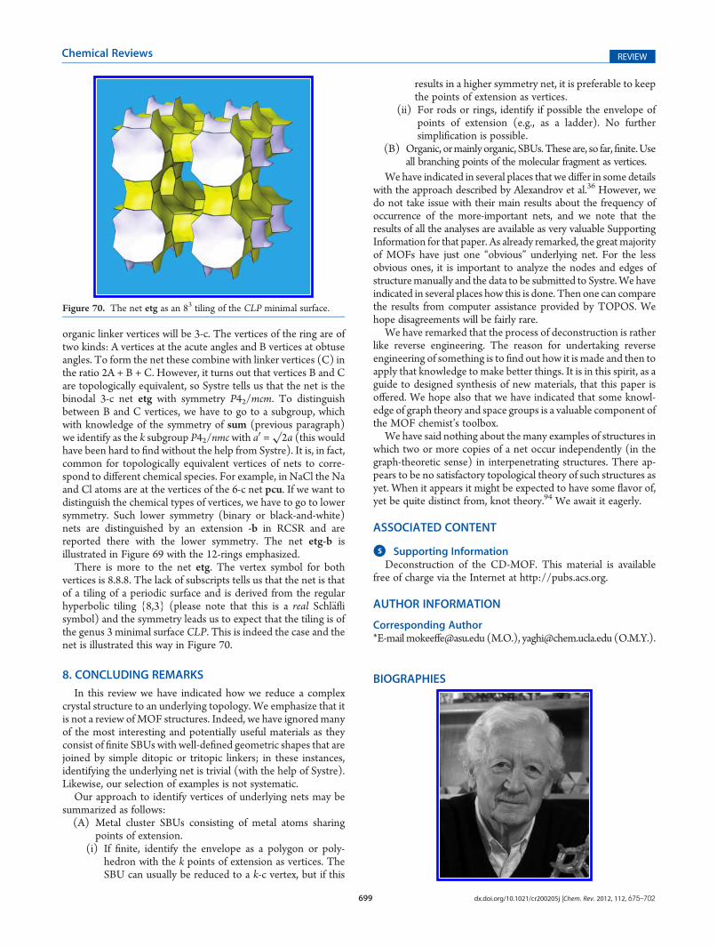
699 dx.doi.org/10.1021/cr200205j |Chem. Rev. 2012, 112, 675–702
Chemical Reviews REVIEW
organic linker vertices will be 3-c. The vertices of the ring are oftwo kinds: A vertices at the acute angles and B vertices at obtuseangles. To form the net these combine with linker vertices (C) inthe ratio 2A + B + C. However, it turns out that vertices B and Care topologically equivalent, so Systre tells us that the net is thebinodal 3-c net etg with symmetry P42/mcm. To distinguishbetween B and C vertices, we have to go to a subgroup, whichwith knowledge of the symmetry of sum (previous paragraph)we identify as the k subgroup P42/nmcwith a0 =
√2a (this would
have been hard to find without the help from Systre). It is, in fact,common for topologically equivalent vertices of nets to corre-spond to different chemical species. For example, in NaCl the Naand Cl atoms are at the vertices of the 6-c net pcu. If we want todistinguish the chemical types of vertices, we have to go to lowersymmetry. Such lower symmetry (binary or black-and-white)nets are distinguished by an extension -b in RCSR and arereported there with the lower symmetry. The net etg-b isillustrated in Figure 69 with the 12-rings emphasized.
There is more to the net etg. The vertex symbol for bothvertices is 8.8.8. The lack of subscripts tells us that the net is thatof a tiling of a periodic surface and is derived from the regularhyperbolic tiling {8,3} (please note that this is a real Schl€aflisymbol) and the symmetry leads us to expect that the tiling is ofthe genus 3 minimal surface CLP. This is indeed the case and thenet is illustrated this way in Figure 70.
8. CONCLUDING REMARKS
In this review we have indicated how we reduce a complexcrystal structure to an underlying topology. We emphasize that itis not a review of MOF structures. Indeed, we have ignored manyof the most interesting and potentially useful materials as theyconsist of finite SBUs with well-defined geometric shapes that arejoined by simple ditopic or tritopic linkers; in these instances,identifying the underlying net is trivial (with the help of Systre).Likewise, our selection of examples is not systematic.
Our approach to identify vertices of underlying nets may besummarized as follows:(A) Metal cluster SBUs consisting of metal atoms sharing
points of extension.(i) If finite, identify the envelope as a polygon or poly-
hedron with the k points of extension as vertices. TheSBU can usually be reduced to a k-c vertex, but if this
results in a higher symmetry net, it is preferable to keepthe points of extension as vertices.
(ii) For rods or rings, identify if possible the envelope ofpoints of extension (e.g., as a ladder). No furthersimplification is possible.
(B) Organic, ormainly organic, SBUs.These are, so far,finite.Useall branching points of the molecular fragment as vertices.
We have indicated in several places that we differ in some detailswith the approach described by Alexandrov et al.36 However, wedo not take issue with their main results about the frequency ofoccurrence of the more-important nets, and we note that theresults of all the analyses are available as very valuable SupportingInformation for that paper. As already remarked, the great majorityof MOFs have just one “obvious” underlying net. For the lessobvious ones, it is important to analyze the nodes and edges ofstructuremanually and the data to be submitted to Systre.We haveindicated in several places how this is done. Then one can comparethe results from computer assistance provided by TOPOS. Wehope disagreements will be fairly rare.
We have remarked that the process of deconstruction is ratherlike reverse engineering. The reason for undertaking reverseengineering of something is to find out how it is made and then toapply that knowledge to make better things. It is in this spirit, as aguide to designed synthesis of new materials, that this paper isoffered. We hope also that we have indicated that some knowl-edge of graph theory and space groups is a valuable component ofthe MOF chemist’s toolbox.
We have said nothing about themany examples of structures inwhich two or more copies of a net occur independently (in thegraph-theoretic sense) in interpenetrating structures. There ap-pears to be no satisfactory topological theory of such structures asyet. When it appears it might be expected to have some flavor of,yet be quite distinct from, knot theory.94 We await it eagerly.
ASSOCIATED CONTENT
bS Supporting InformationDeconstruction of the CD-MOF. This material is available
free of charge via the Internet at http://pubs.acs.org.
AUTHOR INFORMATION
Corresponding Author*[email protected] (M.O.), [email protected] (O.M.Y.).
BIOGRAPHIES
Figure 70. The net etg as an 83 tiling of the CLP minimal surface.

700 dx.doi.org/10.1021/cr200205j |Chem. Rev. 2012, 112, 675–702
Chemical Reviews REVIEW
Michael O’Keeffe was born in Bury St Edmunds, England in1934. He attended the University of Bristol (B.S. in 1954, Ph.D.in 1958, and D.Sc. in 1976). He is Regents’ Professor ofChemistry at Arizona State University, where he has been since1963. Past research has included investigations of conductivity,diffusion, defects, and nonstoichiometry in solids and experi-mental and theoretical studies of crystal chemistry. Over the lastdozen years he has collaborated with Prof. Yaghi, his coauthor onthis paper, in applying the theory of periodic structures to thedevelopment of the theoretical basis of designed synthesis ofmaterials, such as MOFs, consisting of linked molecular frag-ments of predetermined shapes (reticular chemistry).
Omar M. Yaghi was born in Amman, Jordan, in 1965. Hereceived his Ph.D. from the University of Illinois—Urbana (1990)with Prof. Walter G. Klemperer. He was an NSF PostdoctoralFellow at Harvard University (1990�92) with Professor RichardH. Holm. He has been on the faculties of Arizona State University(1992�98) and University of Michigan (1999�2006). His cur-rent position is the Irving and Jean Stone Professor in PhysicalSciences, Professor of Chemistry and Biochemistry, andMolecularand Medical Pharmacology at UCLA and he also directs theCenter for Reticular Chemistry. His work encompasses exploringthe synthesis, structure, and properties of inorganic compoundsand the design and construction of new crystalline materials. Hehas also pioneered a global mentoring model for building centersof excellence for scientific collaborations between the UnitedStates and other countries. The model is being implemented incenters established in a growing number of countries in Asia andthe Middle East.
ACKNOWLEDGMENT
M.O. acknowledges very detailed and useful discussions ondeconstructing crystal structures with Vladislav Blatov, CharlotteBonneau, and Davide Proserpio. G�erard F�erey assisted withhelpful correspondence and data for MIL-100 and MIl-101. M.O.also acknowledges support from the U.S. National ScienceFoundation, grant number DMR 0804828. O.M.Y. is supportedby KAIST, WCU program.
REFERENCES
(1) O’Keeffe, M. Chem. Soc. Rev. 2009, 38, 1215.(2) (a) Farha, O. K.; Yazaydin, O. E.; Eriazici, I.; Malliakas, C. D.;
Christos, D.; Hauser, B. G.; Kanatzidis, M. G.; Nguyen, S. T.; Snurr,
R. Q.; Hupp, J. T.Nature Chem. 2010, 2, 944. (b) Yazaydin, A. O.; Snurr,R. Q.; Park, T. H.; Koh, K.; Liu, J.; LeVan,M. D.; Bemin, A. I.; Jakubczak,P.; Lanuza, M.; Galloway, D. B.; Low, J. J.; Willis, R. R. J. Am. Chem. Soc.2009, 131, 18198.
(3) see e.g.Ewald, P. P.; Hermann, C., Eds. Strukturbericht 1913�1928; Akademische Verlagsgesellschaft M. B. H.: Leipzig, 1931.
(4) (a) Wells, A. F. Three-Dimensional Nets and Polyhedra; Wiley:New York, 1977. (b) Wells, A. F. Further Studies of Three-DimensionalNets; Monograph 9; Am. Cryst. Assoc.: Littleton, CO, 1979.
(5) (a) Iwamoto, T. Inclusion Compounds; Atwood, J. L., Davies,J. E. D., MacNicol, D. D., Eds.; Oxford Univ. Press: London, 1991;Chapter 6. (b) Kitazawa, T.; Nishikiori, S.; Iwamoto, T. J. Chem. Soc.Dalton 1994, 3695. (c) Iwamoto, T.; Kitazawa, T.; Nishikiori, S.; Yuge,H. J. Chem. Soc. Dalton 1997, 4127. These papers give references to theextensive earlier work of this group.
(6) (a) Hoskins, B. F.; Robson, R. J. Am. Chem. Soc. 1990, 112, 1546.(b) Robson, R. J. Chem. Soc., Dalton Trans. 2000, 3735.
(7) Bowes, C. L.; Ozin, G. A. Adv. Mater. 1996, 8, 13.(8) Schindler, M.; Hawthorne, F. C.; Baur, W. H. Acta Crystallogr. B
1999, 55, 811.(9) O’Keeffe, M.; Eddaoudi, M.; Li, H.; Reineke, T. M.; Yaghi, O. M.
J. Solid State Chem. 2000, 152, 3.(10) (a) Yaghi, O. M.; O’Keeffe, M.; Ockwig, N. W.; Chae, H. K.;
Eddaoudi, M.; Kim, J.Nature 2003, 423, 705. (b) €Ohrstrom, L.; Larsson,K.Molecular Based Materials: The Structural Network Approach; Elsevier:Amsterdam, 2005.
(11) Ockwig, N. W.; Delgado-Friedrichs, O.; O’Keeffe, M.; Yaghi,O. M. Acc. Chem. Res. 2005, 38, 176.
(12) Eddaoudi, M.; Kim, J.; Rosi, N.; Vodak, D.; Wachter, J.;O’Keeffe, M.; Yaghi, O. M. Science 2002, 295, 469.
(13) (a) Delgado-Friedrichs, O.; O’Keeffe, M.; Yaghi, O. M. ActaCrystallogr. A 2003, 59, 22. (b) Delgado-Friedrichs, O.; O’Keeffe, M.;Yaghi, O.M.Acta Crystallogr. A 2003, 59, 515. (c) Bonneau, C; Delgado-Friedrichs, O.; O’Keeffe, M.; Yaghi, O. M. Acta Crystallogr. A 2004,60, 517. (d) Delgado-Friedrichs, O.; O’Keeffe, M.; Yaghi, O. M. ActaCrystallogr. A 2006, 62, 350. (e) Delgado-Friedrichs, O.; O’Keeffe, M.Acta Crystallogr. A 2007, 63, 418.
(14) Delgado-Friedrichs, O.; O’Keeffe, M.; Yaghi, O. M. Phys. Chem.Chem. Phys. 2007, 9, 1035.
(15) O’Keeffe, M.; Peskov, M. A.; Ramsden, S. J.; Yaghi, O. M.Acc. Chem. Res. 2008, 41, 1782. RCSR can be accessed at rcsr.anu.edu.au.
(16) (a) Ramsden, S. J.; Robins, V.; Hyde, S. T. Acta Crystallogr. A2009, 65, 81. (b) Hyde, S. T.; Delgado-Friedrichs, O.; Ramsden, S. J.;Robins, V. Solid State Sci. 2006, 8, 740. EPINET can be accessed atepinet.anu.edu.au.
(17) (a) Blatov, V. A.Cryst. Rev. 2004, 10, 249. (b) Blatov, V. A. IUCrCompComm Newslett. 2006, 7, 4. TOPOS is available at www.topos.ssu.samara.ru.
(18) (a) Cubic: Fischer, W. Acta Crystallogr. A 2004, 60, 246.(b) Tetragonal: Fischer, W. Acta Crystallogr. A 2005, 61, 435.(c) Hexagonal: Sowa, H.; Koch, E. Acta Crystallogr. A 2006, 62, 379.(d) Orthorhombic: Sowa, H.; Fischer, W. Acta Crystallogr. A 2010,66, 292. (e) Triclinic: Fischer, W.; Koch, E. Acta Crystallogr. A 2003,59, 509. These papers give references to earlier work.
(19) Delgado-Friedrichs, O.; O’Keeffe, M. J. Solid State Chem. 2005,178, 2480.
(20) The term “topology” is widely misused in many areas ofchemistry, even to mean “structure”, as noted: Francl, M. Nature Chem.2009, 1, 334. We call attention to another misuse below.
(21) Delgado-Friedrichs, O.; O’Keeffe, M. Acta Crystallogr. A 2003,59, 35. The program Systre is available at gavrog.org.
(22) O’Keeffe, M. Zeits. Kristallogr. 1991, 196, 21.(23) Baerlocher, Ch.; McCusker, L. B.; Olson, D. H. Atlas of Zeolite
Framework Types, 6th revised ed.; Elsevier: Amsterdam, 2007. www.iza-structure.org/databases/.
(24) Blatov, V. A.; O’Keeffe, M.; Proserpio, D. M. CrystEngComm2010, 12, 44.

701 dx.doi.org/10.1021/cr200205j |Chem. Rev. 2012, 112, 675–702
Chemical Reviews REVIEW
(25) Blatov, V. A.; Delgado-Friedrichs, O.; O’Keeffe, M.; Proserpio,D. M. Acta Crystallogr. 2007, A63, 418.(26) Alexandrov, E. V.; Blatov, V. A.; Kochetkov, A. V.; Proserpio,
D. M. CrystEngComm 2011, 12, 3947.(27) Delgado-Friedrichs, O.; Foster, M. D.; O’Keeffe., M.; Proserpio,
D. M.; Treacy, M. M. J.; Yaghi, O. M. J. Solid State Chem. 2005, 178,2533.(28) Tranchemontagne, D. J.; Ni, Z.; O’Keeffe, M.; Yaghi, O. M.
Angew. Chem., Int. Ed. 2008, 47, 5126.(29) Baburin, I. A.; Blatov, V. A. Acta Crystallogr. B 2007, 63, 79.(30) Vlasselaer, S.; D’Olieslager, W.; D’Hont, M. J. Inorg. Nucl.
Chem. 1976, 38, 327.(31) Bennett, M. W.; Shores, M. P.; Beauvais, M. G.; Long, J. R.
J. Am. Chem. Soc. 2000, 122, 6664.(32) Tranchemontagne, D. J.; Mendoza-Cort�es, J. L.; O’Keeffe, M.;
Yaghi, O. M. Chem. Soc. Rev. 2009, 38, 1257.(33) Li, H.; Eddaoudi, M.; Groy, T. J.; Yaghi, O. M. J. Am. Chem. Soc.
1998, 120, 8572.(34) (a) Chen, B.; Reineke, T. M.; Eddaoudi, M.; Kampf,
J. W.; O’Keeffe, M.; Yaghi, O. M. J. Am. Chem. Soc. 2000, 122,1559. (b) Kim, J.; Chen, B.; Reineke, T. M.; Li, H.; Eddaoudi, M.;Moler, D. B.; O’Keeffe, M.; Yaghi, O. M. J. Am. Chem. Soc. 2001, 123,8239.(35) Wong-Foy, A. G.; Lebel, O.; Matzger, A. J. J. Am. Chem. Soc.
2007, 129, 15740.(36) Chun, H.; Kim, D.; Dybtsev, D. N.; Kim, K. Angew. Chem., Int.
Ed. 2004, 43, 971.(37) Li, H.; Eddaoudi, M.; O’Keeffe, M.; Yaghi, O. M. Nature 1999,
402, 276.(38) Surble, S; Serre, C.; Mellot-Draznieks, C.; Millange, F.; F�erey,
G. Chem. Commun. 2006, 284.(39) (a) Ma, S; Zhou, H.-C. J. Am. Chem. Soc. 2006, 128, 11734.
(b) For a similar SBU, see also the following: Ma, S.; Wang, X.-S.; Yuan,D.; Zhou, H.-C. Angew. Chem., Int. Ed. 2008, 47, 130.(40) (a) Dinca, M.; Dailly, A.; Liu, Y; Brown, C. M.; Neumann,
D. A.; Long, J. R. J. Am. Chem. Soc. 2006, 128, 16874. (b) For a similarSBU, see also the following: Dinca, M.; Han, W. S.; Liu, Y.; Dailly, A.;Brown, C. M.; Long, J. R. Angew. Chem., Int. Ed. 2007, 46, 1419.(41) Cavka, J. H.; Jakobsen, S.; Olsbye, U.; Guillou, N.; Lamberti, C.;
Bordiga, S.; Lillerud, K. P. J. Am. Chem. Soc. 2008, 130, 13850.(42) Chae, H. K.; Kim, J.; Delgado-Friedrichs, O.; O’Keeffe, M.;
Yaghi, O. M. Angew. Chem., Int. Ed. 2003, 42, 3907.(43) (a) Chae, H. K.; Siberio-P�erez, D. Y.; Kim, J.; Go, Y.; Eddaoudi,
M.; Matzger, A. J.; O’Keeffe, M.; Yaghi, O. M. Nature 2004, 427, 523.(b) Furukawa, H.; Ko, N.; Go, Y. B.; Aratani, N.; Choi, S. B.; Choi, E.;Yazaydin, A €O.; Snurr, R. Q.; O’Keeffe, M.; Kim, J.; Yaghi, O. M. Science2010, 329, 424.(44) Natarajan, R.; Savitha, G.; Dominiak, P.;Wozniak, K.;Moorthy,
J. N. Angew. Chem., Int. Ed. 2005, 44, 2115.(45) Sun, D.; Collins, D. J.; Ke, Y.; Zuo, J.-L.; Zhou, H. C. Chem.—
Eur. J. 2006, 12, 3768.(46) Liu, Y.; Eubank, J. F.; Cairns, A. J.; Eckert, J.; Kravtsov, V. Ch.;
Luebke, R.; Eddaoudi, M. Angew. Chem., Int. Ed. 2007, 46, 3278.(47) Chen, B.; Ockwig, N. W.; Millward, A. R.; Contreras, D. S.;
Yaghi, O. M. Angew, Chem. Int. Ed. 2005, 44, 4745.(48) (a) Lin, X.; Jia, J.; Zhao, X.; Thomas, M.; Blake, A. J.; Walker,
A. S.; Chmpness, N. R.; Hubberstey, P.; Schr€oder, M. Angew, Chem. Int.Ed. 2006, 45, 7358. (b) For otherMOFs isoreticular withMOF-505, see:Hu, Y.; Xiang, S.; Zhang,W.; Zhang, Z.;Wang, L.; Bai, J.; Chen, B.Chem.Commun. 2009, 7551.(49) Ma, L.; Falkowski, J. M.; Abney, C.; Lin, W. Nat. Chem. 2010,
2, 838.(50) Dahmam, T.; Rittner, P.; B€oger-Siedel, S.; Gruehn, R. J. Alloys
Compd. 1994, 216, 11.(51) (a) Iwamoto, T.; Shriver, D. F. Inorg. Chem. 1972, 11, 2570.
(b) Abrahams, B. F.; Batten, S. R.; Hamit, H.; Hoskins, B. F.; Robson, R.Angew. Chem., Int. Ed. Engl. 1996, 35, 469. (c) Yuan, A.-H.; Ju, R.-Q.;Chen, Y.-Y.; Li, Y.-Z. CrystEngComm. 2010, 12, 1382.
(52) Robl, G. Mater. Res. Bull. 1992, 27, 99.(53) Stein, O.; Ruschewitz, U. Acta Crystallogr. E 2005, 61, m2680.(54) Wang., F.-K.; Song, X.-K.; Yang, S.-Y.; Huang, R.-B.; Zheng,
L.-S. Inorg. Chem. Commun. 2007, 10, 1198.(55) (a) Yang, S. Y.; Long, L. S.; Huang, R. B.; Zheng, L. S. Chem.
Commun. 2002, 472. (b) Yang, S. Y.; Long, L. S.; Jiang, Y. B.; Huang,R. B.; Zheng, L. S. Chem. Mater. 2002, 14, 3229.
(56) Fang, Q.-R.; Zhu, G.-S.; Xue, M.; Zhang, Q.-L.; Sun, J.-Y.; Guo,X.-D.; Qiu, S.-L.; Xu, S.-T.; Wang, P.; Wang, D.-J.; Wei, Y. Chem.—Eur.J. 2006, 12, 3754.
(57) Fang, Q.-R.; Zhu, G.-S.; Jin, Z.; Xue, M.; Wei, X.; Wang, D.-J.;Qiu, S.-L. Angew. Chem., Int. Ed. 2006, 45, 6126.
(58) Sra, A. K.; Rombaut, G.; Lahitete, F.; Golhen, S.; Ouahab, L.;Mathoni�ere, C.; Yakhmi, J. V.; Kahn, O. New J. Chem. 2000, 24, 871.
(59) (a) Chun, H. J. Am. Chem. Soc. 2008, 130, 800. (b) Chun, H.;Jung, H.; Seo, J. Inorg. Chem. 2009, 48, 2043.
(60) (a) Eddaoudi, M.; Kim, J.; Wachter, J. B.; Chae, H. K.O’Keeffe, M.; Yaghi, O. M. J. Am. Chem. Soc. 2001, 123, 4368.(b) Moulton, B.; Lu, J.; Mondal, A.; Zaworotko, M. J. Chem.Commun. 2001, 863.
(61) Wang., H.-N.; Meng, X.; Yang, G.-S.; Wang, X.-L.; Shao, K. Z.;Su, Z.-M.; Wang, C.-G. Chem. Commun. 2011, 47, 7128.
(62) (a)Nouar, F.; Eubank, J. F.; Bousquet, T.;Wojtas, L.; Zawarotko,M. J.; Eddaoudi, M. J. Am. Chem. Soc. 2008, 130, 1833. (b) Zhou, Y.; Park,M.; Hong, S.; Lah, M. S. Chem. Commun. 2008, 2340.
(63) (a) Hong, S.; Oh, M.; Park, M.; Yoom, J. W.; Chang, J.-S.; Lah,M. SChem. Commun. 2009, 5397. (b) Zhao, D.; Yuan, D.; Sun, D.; Zhou,H.-C. J. Am. Chem. Soc. 2009, 131, 9186. (c) Yan, Y.; Telepeni, I.; Yang,S. H.; Lin, X.; Kockelmann, W.; Dailly, A.; Blake, A. J.; Lewis, W.;Walker, G. S.; Allan, D. R.; Barnett, S. A.; Champness, N. R.; Schroder,M. J. Am. Chem. Soc. 2010, 132, 4092. (d) Yuan, D.; Zhao, D.; Sun, D.;Zhou, H.-C. Angew. Chem. Int. Ed 2010, 49, 5357.
(64) Guo, Z.;Wu,H.; Srinivas, G.; Zhou, Y.; Xiang, S.; Chen, Z.; Yang,Y; Zhou,W.;O’Keeffe,M.; Chen, B.Angew. Chem., Int. Ed. 2011, 50, 3178.
(65) Moriera deOlivera,M.; Eon, J.-G.ActaCrystallogr.2011,A67, 240.(66) Chen, Z.; Xiang, S.; Liao, T.; Yang, Y.; Chen, S.; Zhou, Y.; Zhao,
D.; Chen, B. Cryst Growth Des. 2010, 10, 2775.(67) Jia, J.; Sun, F.; Fang, Q.; Liang, X.; Cai, K.; Bian, Z.; Zhao, H.;
Gao, L.; Zhu, G. Chem. Commun. 2011, 47, 9167.(68) Ma, L.; Mihalcik, D. J.; Lin, W. J. Am. Chem. Soc. 2009,
131, 4610.(69) Batten, S. R.; Hoskins, B. F.; Robson, R. J. Am. Chem. Soc. 1995,
117, 5385.(70) (a) Zhang, X.-M.; Zheng, Y.-Z.; Li, C.-R.; Zhang, W.-X.; Chen,
X. M. Cryst. Growth Des. 2007, 7, 980. (b) Jia, J.; Lin, X.; Wilson, C.;Blake, A. J.; Champness, N. R.; Hubbersty, P.; Walker, G.; Cussen, E. J.;Schr€oder, M. Chem. Commun. 2007, 840.
(71) Volkringer, C.; Popov, D.; Loiseau, T.; Guillou, N.; F�erey, G.;Haouas, M.; Taulelle, F.; Mellot-Draznieks, C.; Burghammer, M.;Riekel, C. Nature Mats. 2007, 6, 760.
(72) Zhang, X.-M.; Lv, J.; Ji, F.; Wu, H.-S.; Jiao, H.; Schleyer, P. v. R.J. Am. Chem. Soc. 2011, 133, 4788.
(73) (a) Perry, J. J., IV; Kravtsov, V. Ch.; McManus, G. J.; Zaworotko,M. J. J. Am. Chem. Soc. 2007, 129, 10076. (b) Perry, J. J, IV; Perman, J. A.;Zaworotko, M. J. Chem. Soc. Rev. 2009, 38, 1400.
(74) Wang, X.-S.; Ma, S.; Forster, P. M.; Yuan, D.; Eckert, J.; L�opez,J. J.; Murphy, B. J.; Parise, J. B.; Zhou, H.-C. Angew. Chem., Int. Ed. 2008,47, 7263.
(75) Smaldone, R. A.; Forgon, R. S.; Furukawa, H.; Gassensmith,J. J.; Slawin, A. M. Z.; Yaghi, O. M.; Stoddart, J. F. Angew. Chem., Int. Ed.2010, 49, 8630.
(76) F�erey,G;Mellot-Draznieks, C.; Serre, C.;Millange, F.; Dutourm,J.; Surbl�e, S.; Margiolaki, I. Science 2005, 239, 2040.
(77) O’Keeffe, M. Mater. Res. Bull. 2006, 41, 911.(78) F�erey, G.; Serre, C.; Mellot-Draznieks, C.; Millange, F.; Surbl�e,
S.; Dutour, J.; Margiolaki, I. Angew. Chem., Int. Ed. 2004, 43, 6296.(79) Park, Y. K.; Choi, S. B.; Kim, H.; Kim, K.; Won, B.-H.; Choi, K.;
Choi, J.-S.; Ahn, W.-S.; Won, N.; Kim, S.; Jung, D. H.; Choi, S. H.; Kim,

702 dx.doi.org/10.1021/cr200205j |Chem. Rev. 2012, 112, 675–702
Chemical Reviews REVIEW
G.-H.; Cha, S.-S.; Jhon, Y. H.; Yang, J. K.; Kim, J. Angew. Chem., Int. Ed.2007, 46, 8230.(80) Rosi, N. L.; Kim., J.; Eddaoudi, M.; Chen, B.; O’Keeffe, M.;
Yaghi, O. M. J. Am. Chem. Soc. 2005, 127, 1504.(81) F�erey, G.; Serre, C. Chem. Soc. Rev. 2009, 38, 109.(82) (a) Serre,C;Millange, F.; Thouvenot, C.;Nogu�es,M.;Marsolier,
G.; Lou€er, D.; F�erey, G. J. Am. Chem. Soc. 2002, 124, 13519. (b) Barthelet,K.; Marrot, J.; Riou, D.; F�erey, G. Angew. Chem., Int. Ed. 2002, 41, 28.(83) Rosi, N. L.; Eddaoudi, M.; Kim, J.; O’Keeffe, M.; Yaghi, O. M.
Angew. Chem., Int. Ed. 2002, 41, 284.(84) Zhang, X.-H.; Hao, Z.-M.; Zhang, X.-M. Chem.—Eur. J. 2011,
20, 5585.(85) Colombo, V.; Galli, S.; Choi, H. J.; Han, G. D.; Maspero, A.;
Palmisano, G.; Masciocchi, N.; Long, J. R. Chem. Sci. 2011, 2, 1311.(86) Bondar, O. A.; Lukashuk, L. V.; Lysenko, A. B.; Krautscheid, H;
Rusanov, E. B.; Chernega, A. N.; Domasevitch, K. V. CrystEngComm2008, 10, 216.(87) (a) Perles, J.; Iglesias, M.; Martin-Liengo, M.-�A.;Monge, M. �A.;
Valero, C,R; Snejko, N. Chem. Mater. 2005, 17, 5837. (b) Miller, S. R.;Wright, P. A.; Serre, C.; Loiseau, T.; Marrot, J.; F�erey, G. Chem.Commun. 2005, 3850.(88) Monge, �A.; G�andara, F.; Guti�errez-Pueblo, E.; Snejko, N.
CrystEngComm 2011, 13, 5031.(89) (a) Gao, X, D.; Zhu, G. S.; Li, Z. Y.; Sun, F. X.; Yang, Z, H;
Qiu, S. L.Chem. Commun. 2006, 3172. (b) Chen, B.; Yang, Y.; Zapata, F.;Lin, G.; Qian, G.; Lobkovsky, E. B. Adv. Mater. 2007, 19, 1693.(c) Gustavsson, M.; Bartosewicz, A.; Martin-Matute, N.; Sun, J.; Grins,J.; Zhao, T.; Li, Z.; Ahu, G; Zou, X. Chem. Mater. 2011, 22, 3316.(90) Guo, Z.; Xu, H.; Su, S.; Cai, J.; Dang, S.; Xiang, S.; Qian, G.;
Zhang, H.; O’Keeffe, M.; Chen, B. Chem. Commun. 2011, 19, 5551.(91) Gadipelli, S.; Ford, J.; Zhou, W.; Wu, H.; Udovic, T. J.; Yildirum,
T. Chem. Eur. J. 2011, 17, 6043.(92) Dan-hardi, M.; Serre, C.; Frot, T.; Rozes, L.; Maurin, G.;
Sanchez, C.; F�erey, G. J. Am. Chem. Soc. 2011, 131, 10857.(93) Sumida, K.; Hill, M. R.; Horike, S.; Dailly, A.; Long, J. R. J. Am.
Chem. Soc. 2009, 131, 15120.(94) Hyde, S. T.; Delgado-Friedrichs, O. Solid State Sci. 2011, 13,
676.