dedicated to quality model railroading
TRANSCRIPT

Dedicated to Quality Model Railroading VOL. 5, NO.40 ROCHESTER, N.Y. APRIL 2006 Modeling an Interlocking Panel - Part III by Bill Carr ………….. ….….…….……………….. 2 The Care and Feeding of the Tortoise by Ray Howard ………………….………………………. 7 Photo Gallery - The Rochester Model RR Club by Pete Darling …………………….……………. 9 Track Car Operator Training by Harold Russell …………………. ……………….…………… 10 Editing Model Railroad Digital Images – Part III by Fred Cupp ……………………..………… 12 Doctor Duck – Alan Asks About DCC – The NCE Power Pro System ………………. ….…………………15 Train Events – 2006 Calendar ……………………………….………….………..…….…………………...17
Rochester Model Rails
A fall scene from the Rochester Model Railroad Club layout, Rochester, NY.
PDF created with pdfFactory trial version www.pdffactory.com

Modeling an Interlocking Panel - (Selkirk Tower) - Part III
by Bill Carr Selkirk Tower In Part I & II of Modeling an Interlocking Panel, I discussed modeling a prototypical Interlocking Plant based upon the 1950’s Selkirk Tower, located at CP-SK, along the Selkirk Branch, and at the East End of Selkirk Yard, 10 miles south of Albany, NY. A photo of this tower appears in the 2005 summer issue of Classic Trains. My intention was to depict a typical electronic interlocking plant and the operations methods required of the day in executing complex train movements in and
around this very busy Northeastern freight yard. The result was a 2 foot x 4 foot panel controlling over 30 turnouts, 62 detected blocks, and 34 signal heads by utilizing a computer interface and electronic controls from the C/MRI series originally authored by Bruce Chubb in the 1980’s. This interface mimics the electronic, electromechanical, and
mechanical interlocking controls found in U.S. railroad towers, many of which are abandoned or demolished today, including the tower at Selkirk, NY. Part III will include brief descriptions of connecting the railroad to the computer interface, the basic flow of control utilized within the interlocking logic, the train table modules constructed for this project, and the use of automated DCC control. The Block The concept of interlocking logic is based upon a block. A block is a subjectively determined stretch of track work that prevents collisions, enhances safety of operation, and increases the flow of traffic. A block might, or might not contain a switch, as well as related traffic flow signaling. Below are examples of blocks used throughout the modeling construction of Selkirk Interlocking Plant. I first chose each of the 32 turnouts to become a block. This type of block starts from the clearance of the points to the edge of the fouling point on the main and divergent rails. Each turnout in any crossover becomes an individual block. For
April 2006 Rochester Model Rails Page 2
PDF created with pdfFactory trial version www.pdffactory.com

the diamond at CP-SK, there are 3 parallel tracks crossing a single track. Two signal bridges protect the parallel tracks, whereas two single-headed mast signals protect the single track forming the three diamonds. The diamond, therefore, contains 4 blocks. Next, sections of track work between these various points become blocks. For control purposes, I also chose to include a stretch of track work facing each entrance signal mast as a block to be detected. I refer to these blocks as entrance/exit blocks. Since the interlock contains three interchange track sections, I chose to make the single diamond crossing track and the southeastern quadrant interchange track electrically separate reverse loops which as also block-detected. In total, there are 62 blocks occupancy-detected using the latest Bruce Chubb DCC optimized circuit – DCCOD. Each turnout reports back the respective position as either placed in the “Normal” or “Reverse” position. Having 32 switch motors, this would mean 64 inputs of position to report. However, with 10 crossovers within the interlocking plant, I wired the reverse position contacts for each pair in series, reducing the number of inputs required in the cabling and computer interface as well as providing better insurance that the crossover is safe to traverse. Signals are placed at the entrance blocks and diamond crossings. Each head is a tri-lead, bi-color LED searchlight style signal head. Yellow is achieved by
providing voltage and current across two of the three leads, with the third acting as ground. Flashing is achieved by turning the signal head on and off every three to four program loops. Parameter
files read by the computer program allow alteration of the signal aspects before any operating session. During one session, a signal aspect might display Flashing Green over RED, but on the next session, it might display RED over YELLOW. Railroad and Panel Connections Regarding the trackside output interface, in order to control turnouts and signals, circuits are employed which allow a control line to be brought to ground state by the computer interface. Two such lines are required for Turnouts for controlling the individual Capacitive Discharge Circuits, one per turnout. Signal heads are also controlled by a circuit that allows the two control lines for each head to be brought to ground, one for GREEN, one for RED, and both for YELLOW.
April 2006 Rochester Model Rails Page 3
PDF created with pdfFactory trial version www.pdffactory.com

Input to the computer interface is achieved by dropping an input line to ground. In the case of turnout positions, the center contact on a switch motor is grounded; the other two lines are connected to the computer interface. For a lock to be detected, the occupancy sensing circuit must drop its output line to ground, which is connected to an input line on the computer interface.
In the case of my Selkirk Tower Interlocking Plant, a set of computer interface cards called a SUSIC node, were placed upon a roll-around cart under the train tables. AMP-Pluggable 25pair telephone cabling connects the various under-table mounted circuitry to these computer interface cards.
Interlocking Panel controls, such as push buttons, levers, and LEDS are connected directly to the computer interface without special circuitry. Some modeled panels include speakers to mimic the “codes” being sent to, and received from, the railroad trackside components in the form of “clicking sounds. A second SUSIC Node connects these various components to the computer
interface. All nodes are tied together in a serial daisy chain communications cable back to the computer. Modular Railroad Tables Selkirk Interlocking Plant is constructed on three main 2foot x 8foot modular tables. Each table is of basic 1x4 pine construction with multiple cross members supporting a layer of ½ inch homasote. I constructed two appendages to represent the River Line and the Albany Secondary track work. On top of the homasote is cork roadbed and track work. RIX Twincoil switch motors power each turnout. Sunrise dual head signals are used on Bachmann signal bridges and TOMOR dual head signal masts protect each entrance block. The signal masts and bridges contain pluggable harnesses to facilitate transportation between train shows. All power connections between tables are MOLEX 9 or 12 pin connectors with 14ga stranded wiring. Most control lines are 18-24 gauge wire terminating at an AMP plug. All power and control line cabling terminates at a “POWER” cart under the railroad that supports the Laptop computer, a C/MRI node, NCE DCC system, and power supplies.
April 2006 Rochester Model Rails Page 4
PDF created with pdfFactory trial version www.pdffactory.com

Computer Interlocking Logic The basic flow of a C/MRI type system begins with the reading of turnout positions, block occupancy, and panel switch or lever positions. This information is then stored within the computer application. Using these various inputs, the application works through the custom-written decision-tree logic, constructs a set of output requests (such as throw a switch or turn on a signal head), then stores this information within the application, and, finally, sends these instructions back to the computer interface via the C/MRI. The following is a brief list of sequences performed iteratively multiple times per second: 1. Read turnout positions 2. Read block occupancy 3. Read traffic flow levers, route selection rotaries, and code buttons 4. Read turnout lever positions and code
buttons 5. Construct diamond signal control LED
outputs 6. Read routing information 7. Lock Route if all elements properly positioned
such as switches, blocks, signals, levers 8. Set Route Timer 9. Set Entrance / Exit signal control outputs 10. Output Signal Control 11. Output Turnout Control 12. Output Panel LED displays 13. Return to step 1 Automated Train Control In order to demonstrate the use of the Selkirk Tower at train shows, I incorporated the binary computer-generated command codes for NCE’s DCC system into the overall application. When the tower operator selects a route, and the application locks this route, if an engine is sitting at the entrance block, the computer sends the necessary DCC commands to the engine to traverse the interlock. Upon arrival at the exit block, the computer program idles the engine, sets the direction for the reverse movement, and leaves the engine sitting at the “exit” (now entrance) block for the next time a route is established across the interlock. This process frees up the tower operator to demonstrate the Interlocking panel without too much worry about having to also control the engine movements across the interlock. When the train table modules are connected to my large SELKIRK Yard modular project, this later feature is simply
April 2006 Rochester Model Rails Page 5
PDF created with pdfFactory trial version www.pdffactory.com

deactivated, allowing engineers to run full trains across the interlock obeying the signals as they proceed. Summary This project was a rewarding adventure combining my electronic, computer programming, and model railroading skills into a single concept to best depict a prototype operations at a complex interlocking plant. For those interested parties requesting more detailed information, please contact me via the Tuesday Night Gang or the publisher of this newsletter, Dick Senges. More detailed information on CP-SK Selkirk Tower project will be available in the soon-to-be-published C/MRI Applications Handbook Version 3 in the chapter covering interlocking plant examples. This book is being produced by Bruce Chubb, the original author and designer of the Computer / Model Railroad Interface (C/MRI). Photos of this project can also be found on the Yahoo Users group site: CMRI_USERS under the PHOTOS section in folder CP-SK. This project will be on display, running in demo mode with panel and train table modules, beginning with the March, 2006 R.I.T. Train show. The engines, representing trains, will traverse the train tables back and forth from entrance to exit blocks, automatically controlled via the computer interface logic, while Selkirk Tower operators perform the duties of setting up and locking various routes. As the trains (engines) proceed across the interlock, block occupancy and signal repeaters will be displayed upon the track diagram of the Interlocking Tower Panel.
April 2006 Rochester Model Rails Page 6
PDF created with pdfFactory trial version www.pdffactory.com

The Care and Feeding of the Tortoise
(Aka - wiring and installation of the Tortoise Switch Machine)
by Ray Howard
The Tortoise Switch Machine by Circuitron is a well-built and easy to install product. I have never heard of one failing and after installing a few on my layout, I will use nothing else. This article is about how I install and use the Tortoise on my layout. Understand there are many perfectly good ways to install and wire this machine depending on your individual requirements. I first fasten the Tortoise to a small piece of luan plywood. The one pictured is mounted on a piece of scrap wainscoting. Several people I know mount the Tortoise on PC Board before installing it on the layout. I then pre-wire each of the contacts on the Tortoise to a terminal strip, as I do not like to solder over my head looking up at the work. Contacts #1 and #8 are the feeds to the DC power source. (You will need to use a DPDT toggle switch to be able to reverse the direction of the current to the tortoise.) The tortoise has two built in SPDT contact switches that can be used to power the frog of the turnout or to run signals on the layout or other effects. Since I model the year 1925 and so do not have lighted signals and use DCC, I use both sets together to power the frog. The contacts are rated at 2 amps and since my DCC power is 5 amps to the track, it builds some redundancy into the system in case of shorts at the frog. To tie the contacts together, they are wired as follows: #4 and #5 are wired together. This is the feed to the frog. #2 and #6 are wired together as are #3 and #7. This makes the polarity the same from both sets of contacts. Note: label things! It makes it much easier under the layout when you are installing them. I power the Tortoise using a 16v 3amp DC power source. Since this is more than the rating of the tortoise, I wire them in series when I have two that are always thrown together (such as a crossover). For single units, I wire a resistor in series with it to lower current draw to the unit. For most applications, a 9v DC wall wart type converter rated for 500 mA will power several machines with power to spare. Although the Tortoise is rated for 12v, they seem to operate best at 9 volts.
April 2006 Rochester Model Rails Page 7
PDF created with pdfFactory trial version www.pdffactory.com

[The following instructions are for use with plywood or other material that you can firmly fasten a screw to under the layout. There are other ways to install the machine if you use a foam base.] To install the Tortoise machine under the layout, drill a 1/2” hole directly under the hole in the throwbar of the turnout (Measure twice, drill once). Install the turnout on the layout making sure the hole is centered under the switch throwbar. At this point, I use folded heavy paper to firmly hold the switch points in the center between the stock rails. Pre-drill 4 holes, one at each corner of the mounting board for fastening the assembly to the layout base, then carefully place the tortoise assembly in place under the layout making sure the throwbar on the tortoise moves in the same direction of travel as the points of the turnout. (It helps to have the Tortoise movement centered or at the halfway point also.) Then tighten one of the screws to hold the assembly in place. Use a “screw starter” or a small awl to start the holes for the screws. At this point, I attach the feeds that go to the DPDT switch to operate the tortoise. Remove the folded paper so the switch points can move again. Then, take it out for a test drive! Check to make sure the points are firmly held in place when the turnout is in each position. Make any final adjustments to the position of the tortoise under the layout, and put in the other screws to hold it firmly in place. If the points move backwards from the way you want, you can either reverse the wires #1 and #8 at the terminal block or just turn the DPDT toggle the other way around. The final step is to attach the wiring to whatever you are going to power with the internal toggles of the tortoise. I bring DCC power from the track or from my buss network to the terminal strip (#2 -# 6 and #3 and #7) then connect the feed (#4 and #5) to the frog. Fire up a loco and check out the turnout. You have a 70% chance that the loco will short out on the frog. (I don’t know why, it just works out that way.) Don’t panic; don’t call 911 just reverse the power feeds from the track or the buss. Problem solved.
Some hints that may help. 1. Hex head screws and a hex nut driver are much easier to use while working over your head under the layout. 2. If you recess your toggle switches into the fascia around your layout, they won’t catch on clothing when you walk by. 3. The Tortoise can be mounted on the point side or the frog side of the turnout equally well. I have also used them with a specially made remote wiring set up to throw the switch points when I could not place them directly under the turnout. 4. Spade lugs crimped and soldered (I like good power connections) onto the wires make them easy to connect to the terminal strip.
April 2006 Rochester Model Rails Page 8
PDF created with pdfFactory trial version www.pdffactory.com

April 2006 Rochester Model Rails Page 9
Photo Gallery
Scenes from the Rochester Model Railroad Club, Rochester, NY. They will be holding their annual Open House and Sale on Saturday March 11 and Sunday March 12. Location: 150 South Clinton Avenue in the basement of the First Universalist Church. Hours: Saturday 10:00am – 5:00pm and Sunday 1:00pm – 5:00pm. The Flea Market is Saturday only. Admission: $3.00 for adults, $2.00 ages 6 – 12, under 6 free with adult. Information: Tom McColloch 585-872-6106.
Digital images by Pete Darling.
PDF created with pdfFactory trial version www.pdffactory.com

1
2006 TRACK CAR OPERATOR TRAINING
Training for train enthusiasts who wish to be Track Car Operators at our local railroad museums will commence in March 25 and continue through May 20. The schedule on the following page shows the exact dates, times, the type of training offered. This training is required for new persons as well as experienced operators. All modelers and rail enthusiasts are welcome to share in this rewarding, fun, summertime experience. All operators should be members of either the New York Museum of Transportation or the Rochester Chapter of the National Railway Historical Society.
Experienced Operators
Training will consist of a one-hour classroom session plus a half-day
‘hands-on’ session. There are several dates from which you can choose your classroom training.
This year we are attempting to make the ‘hands-on’ training more
comprehensive requiring several hours. This training will consist of a minimum of at least one single direction trip with each of two track cars. To even out the attendance we have broken the training segments (depending on the first letter of your last name) into what we hope are equal attendance portions. If for some reason, you cannot attend your designated ‘hands-on’ time; call Harold Russell after March 12th at 427-9159 or E-mail at [email protected].
New Operators
Classroom training dates for new operators will be same as the
experienced personnel. These are held in the Gallery at the New York Museum of Transportation at 6393 East River Road. Entrance is through the office door at the southwest corner of the building. No appointment is necessary for the classroom sessions.
The ‘hands-on’ training for you will be more extensive and separate
from than that of the experienced operators. It will consist of the preparation, start up and shut down procedures for each of two track cars plus a minimum of two hours of operation with each.
To avoid uneven attendance, please make an appointment for your
‘hands-on’ training. Please refer to the schedule for the available dates. To make your appointment or if you have questions, contact call Harold Russell after March 12th at 427-9159 or E-mail at [email protected].
April 2006 Rochester Model Rails Page 10
PDF created with pdfFactory trial version www.pdffactory.com

DATE TYPE OPERATORS TIME LOCATION March 25, 2006 Classroom Experienced and New 9 to 10 AM NYMT* April 1, 2006 Classroom Experienced and New 9 to 10 AM NYMT April 8, 2006 Classroom Experienced and New 9 to 10 AM NYMT April 22, 2006 Classroom Experienced and New 9 to 10 AM NYMT Hands-on Experienced A thru H 9 to 12 AM NYMT Hands-on Experienced I thru M 1 to 4 PM NYMT April 29, 2006 Hands-on Experienced N thru S 9 to 12 AM NYMT Hands-on Experienced T thru Z 1 to 4 PM NYMT May 6, 2006 Hands-on New By Appointment NYMT May 7, 2006 Classroom Experienced and New 9 to 10 AM NYMT Hands- on
Make up Experienced A thru Z 9 to 12 AM NYMT
May 13, 2006 Hands-on New By Appointment NYMT May 20, 2006 Hands-on
Make up New By Appointment NYMT
April 2006 Rochester Model Rails Page 11
Track Car Training Schedule for 2006
* NYMT – New York Museum of Transportation, Industry, NY.
PDF created with pdfFactory trial version www.pdffactory.com

Editing Model Railroad Digital Images – Part III
by Fred Cupp Way back in part 1, we saw the effect of the "Sharpen" function. I promised to show you the converse function, "Blur". You may not think it wise to blur your fine photo, but there are times that it may be necessary. Take the case of an historical railroad photo. If you zoom in to examine any details, such as the man standing on the track, the halftone dot printing pattern is very distracting. (See photo # 1) The first step to improve or reduce the dot interference pattern must average out the small variations in adjacent pixel areas. Careful use of the blur function, (adjusting the size of the area to average), can virtually eliminate the interference of the printing dots. (See photo # 2) Unfortunately, this also blurs the overall quality of the photo. Next, the sharpen function, (applied twice), is used the replace the sharpness somewhat, while leaving the dot pattern virtually eliminated. (See photo # 3)
Photo 1 Dot Pattern Photo 2 Blur, dots gone Photo 3 Details sharpened Now I want to run in another clever tool, one that will not be used too often, but when it is needed, it is sheer magic. This tool will permit you to take two photographs and "STITCH" them together. In 1957, passenger service on the Pennsy Buffalo line was about to become extinct. I decided that I should preserve the image of the station serving the town of my birthplace. (As if anyone but me cared?) At the station, I discovered that when standing across the tracks from the station, I could only get a little more than 1/2 of the building in the picture. My old Century Graphic "Press Camera" with only one lens, prevented me from moving back. Rather than having no picture at all, I took two shots, to preserve this scene. Those 2-1/4" x 3-1/4" negatives went into the big storage box, and only emerged about 1999, re-appearing as images on my computer. After conversion to positive images, a number of preparation steps were needed: 1.) Rotating the left image about 1 degree to maintain a straight roofline. 2.) Selecting a point to join the two together, (the left edge of the chimney). 3.) Adjusting the brightness slightly to the same value at both edges of the selected splice. 4.) Cropping the left photo to provide a sharp edge to overlap the right photo.
April 2006 Rochester Model Rails Page 12
PDF created with pdfFactory trial version www.pdffactory.com
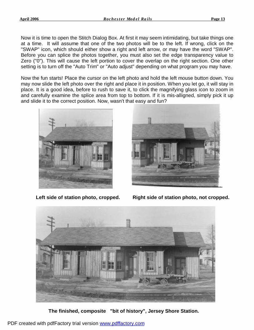
Now it is time to open the Stitch Dialog Box. At first it may seem intimidating, but take things one at a time. It will assume that one of the two photos will be to the left. If wrong, click on the "SWAP" icon, which should either show a right and left arrow, or may have the word "SWAP". Before you can splice the photos together, you must also set the edge transparency value to Zero ("0"). This will cause the left portion to cover the overlap on the right section. One other setting is to turn off the "Auto Trim" or "Auto adjust" depending on what program you may have. Now the fun starts! Place the cursor on the left photo and hold the left mouse button down. You may now slide the left photo over the right and place it in position. When you let go, it will stay in place. It is a good idea, before to rush to save it, to click the magnifying glass icon to zoom in and carefully examine the splice area from top to bottom. If it is mis-alligned, simply pick it up and slide it to the correct position. Now, wasn't that easy and fun?
Left side of station photo, cropped. Right side of station photo, not cropped.
The finished, composite "bit of history", Jersey Shore Station.
April 2006 Rochester Model Rails Page 13
PDF created with pdfFactory trial version www.pdffactory.com

We will conclude this series with a fun bit of image trickery. A friend, John Kocet, had just purchased a new steam loco and had it on my layout. He commented that it looked so good he was ready to climb up in the cab, if only he could. I then posed him on our back deck for the first shot in the row of three. Using a lasso tool is a pain! You will test your patience in using this. Carefully draw an outline, slightly oversize, around the subject. Now, zoom in really close and use the eraser tool to clean off the edges left by the lasso selection tool. Last, copy the isolated image portion and save it as a new blank photo. The third photo shows this cleaned up image.
One last step remains. -- By trial and error, resize the image and test it on the "cab" photo to check the size, relative to the cab window. Use the "UNDO" tool until the result is pleasing.
John Kocet, sitting proudly in the cab of his new HO loco ! Well, dear reader, this concludes our rapid tour through the wonderland of digital imaging. I trust that the trip has challenged you to apply your imagination to your own photo gallery. If I can be of assistance, you may send your comments or questions to: < [email protected] >.
April 2006 Rochester Model Rails Page 14
PDF created with pdfFactory trial version www.pdffactory.com

Alan writes: I just purchased a new DCC system, the NCE Power Pro Radio 5 Amp System, and have some questions. For example, how do I change the cab to “Yard Mode”? In looking in the NCE Power Pro System Reference Manual I cannot find this in the “Table of Contents” on page 5 or on the” Programming Menus Table of Contents” on page 39. Also, should I twist my bus wires? I also have some questions about the radio system that are not in the Manual. Can you help? Doc: Let me first say that “a certain amount of technical expertise is required” to understand and operate sophisticated DCC systems. To answer you specifically, “Yard Mode” is listed on Page 22 under Cab Set Up (# 5), twisted bus wires can be found on Page 10, and information on the radio system is not in the Manual but included in the NCE ProCab Wireless Supplement that should be included with your system. To aid in answering your other concerns, see the following Index. Good luck.
NCE Power Pro System Reference Manual
February 2006 - # 05240300
Index*
April 2006 Rochester Model Rails Page 15
Ask Doctor Duck
PDF created with pdfFactory trial version www.pdffactory.com

ASCII Command Set 72 Accessory Decoders, Program 67 Add Loco, ProCab, Consist 20 Adding a Loco to an Advanced Consist 30 Address, ProCab 18 Address, Long 2, 27 Address, Short 2, 27 Address – Programming a Locomotive 1 – 2 Address Programming, Main, (Option 1) 41 Advance Consists, Setting Up 28 Assigning a Loco to a Cab 48 BIN CV 41 Backlight, LCD 22 Back Up Key 76 Basic Set Up 0 Battery, Cab (See Wireless Supplement) Battery, Command Station 13 Battery, Connect Jumper 13 Binary Command Set 72 Bell, ProCab 19 Boosters, Multiple 16 Booster, Power 14 – 16 Brake Key 19 Browse Consists 70 Button Numbering Scheme 24 Buttons, Commonly Used, ProCab 19 Cab 05 R 80 Cab 04 P 80 Cab Bus 12 Cab Bus Cable 25 Cab Parameters, Set 65 Cab Set Up 22 Cable, Cab Bus, Wiring 25 Cable, Connectors 25 Cable, Straight Through 25 Changing the Lead/Rear Loco, Consist 31 Clear, ProCab, Consist 20
PDF created with pdfFactory trial version www.pdffactory.com

Clearing an Advanced Consist 31 Clock, Setting the System 38, 49 Command Station 12 Command Station, Set Up 38, 59 Common Rail Layouts 16 Communications Parameters 72 Computer Interface Port 12 Computer Interface, RS 232 72 - 75 Connectors, RJ – 12 25 Consist Address 29 Consist, Advanced 28 Consist, Old Style 28 Consist Set Up Group 20 Consists, Browse 70 Control Bus 12 Control Bus Sockets 15 Controlling Headlights/Other Decoder Functions 27 Copyright and Trademarks 78 Crossovers 10 Customer Service 4 CVs CV Programming, Main, (Option 2) 42 CV Programming 56 CV 2 (start voltage) 54 CV 3 (acceleration) 54 CV 4 (deceleration) 55 CV 5 (maximum voltage) 54 CV 6 (mid speed voltage) 54 CV 9 (motor PWM frequency) 55 CV 19 77 CV 23 36 CV 24 36 CV 29 (CFG) 7, 83 CV 49 (QSI) 47 CV 50 (QSI) 47 CV 51 (QSI) 47 CV 52 (QSI) 47 CV 56 (QSI) 47 CV 62 36 CV 116 (NCE torque compensation kick rate) 55 CV 117 (NCE torque compensation kick depth) 55
PDF created with pdfFactory trial version www.pdffactory.com

CV 119 (Soundtraxx) 47 CV 120 – 127 (Soundtraxx) 47 DC, Analog Mode 53 DCC Output Voltage, Power Booster 15 - 16 DPDT Switch, Wiring 9 DPDT Switch, with EB3 81 Data Entry/Function Control 20 Deceleration (CV4) 55 Decoders, Installing 8 Decoders, Notes 9 Delete Loco, ProCab, Consist 21 Direction, ProCab 18 Display 26 Double Gapped Layouts 16 Dropping Loco From Advanced Consist 30 EB1, wiring 80 EB3, wiring 81 EPROM, replacement 13 EXPN 21 Emergency Stop, ProCab 19 Enter, ProCab 20 Error Message 51 Escape Key 21 F10 21 F11 21 F12 21 FCC Statement 79 Factory Default Values, “Shifted” Keys 25 Function, Control 20 - 21 Function Mapping 45, 56 Headlight, ProCab 19, 27 Hints, For Operation 76 Horn, ProCab 19
PDF created with pdfFactory trial version www.pdffactory.com

Indexed Programming 47 Installation, General System 9 Installing Decoders 7 Key Table Chart 23 Kick Depth 45, 55 Kick Rate 45, 55 Kick Strength 45, 55 LCD Screen, ProCab 18 Layout Stopped 19 Lead Loco Number, Entering 29 Lighting Effects Programming 46, 58 Locomotive Control Area, ProCab 18 Locomotive Direction, Consist 30 Locomotive, Selecting 26 MRC Decoders 77 Macro, ProCab 20 Macro, Using to Control Turnouts 37 Macros, Programming 68 Mapping, Function 45, 56 Maximum Voltage 54 Menu Navigation Chart 82 Mid-Consist Loco, Adding 30 Mid Speed Voltage 54 Momentum, ProCab 18 Momentum Button, Technical 36 NCE, Address & Phone Number 4 NCE, General 79 NCE, Lighting Effects Programming 46, 58 NCE, Warranty 78 Normal, vs. Yard, Cab Set Up 22 Numbering Scheme, ProCab 24
PDF created with pdfFactory trial version www.pdffactory.com

OPS Mode 38, 41 Option Keys 21 Option, ProCab 19 Operating Procedures, ProCab 26 Operations Mode Programming 41 Power Booster 14, 76 Power Supply P515 80 - 81 ProCab, NCE 18, 76, 81 Prog/Esc/F10 21 Program, What to 41 Program Track, Use 50, 77 Programming Procedures 38 Programming on the Main 41 – 47 Option 1 - Address Programming 41 Option 2 - CV Programming 42 Option 3 - Set Decoder Configuration 42 Option 4 - Set Motor Control Parameters 43 Option 5 - Decoder Output/Function Mapping 45 Option 6 - Set Up NCE Lighting Effects 46 Option 7 - Soundtraxx Tsunami Programming 47 Option 8 - QSI Programming 47 Option 9 - Binary Programming 47 Programming on the Programming Track 38, 50 – 58 Option 1 - Standard Programming 51 Option 2 - Change Any CV in the Decoder 57 Option 3 - Register Programming 57 Option 4 - Paged Programming 58 Option 5 - Direct Programming 58 Option 6 - Set Up NCE Lighting Effects 58 Option 7 - Recovery Programming 58 Programming Accessory Decoders 67 Programming & Extended Function Control 21 Programming Macros 68
PDF created with pdfFactory trial version www.pdffactory.com

Programming Modes 38 Programming Signal Decoders 71 Programming Track, General 9 Programming Track, Terminals 12 Quick Start, 5 Amp System 0 Quick Start, 10 Amp System 0 Quick Start, Completing 1 QSI Programming 47 UTP Panel 81 RJ – 12 Connectors 12, 25 RPT1 80, 81 RS 232 Serial Computer Interface 12, 72 – 75 Radio (See Wireless Supplement) Radio Fix Enable 61 Radio Set Up Menu 21 Rear Loco Direction, Entering 25 Rear Loco Number, Entering 29 Recall, ProCab 2, 19 Reset, Cab 22 Reset, Command Station 59 Reset, Decoder 58 Register System 4 Reverse Loops 10 Reversing Modules 16 Select Accessory, ProCab 20 Select Loco, ProCab 20 Selecting Locomotive or Consist 26 Set Decoder Configuration, Main, (Option 3) 42 Set Up, 5 Amp System 0 Set Up, 10 Amp System 0 Set Up, Consist 20 Shift, ProCab, Programming & Ext. Function 21 Shifted Keys 25 Signal Decoders, Programming 70
PDF created with pdfFactory trial version www.pdffactory.com

Soundtraxx Programming 47 Speed Control, ProCab 18 Specifications, Command Station 12 Specifications, Five Amp Power Station 12 Specifications, Pro Cab 23 Start Voltage 54 Status Light, Booster 14 Status Light, Command Station 12 Straight Through Cable 25 (See Wireless Supplement) 28/128 21, 42 28 or 14 Speed Steps 42 Table of Contents, General 5 Table of Contents, Programming Menus 39 Terminals, Programming Track 12 Track Light 12 Track Terminals, Booster 14 Track Voltage Adjustment 15 Two Locos with One Cab 2 Trouble Shooting 77 Turnouts and Other Accessories 35 Twisted Bus Wires 10 Warranty 78 Whistle, ProCab 19 Wire Gauge 10 Wireless Information (See Wireless Supplement) Wiring 10, 81 Wiring, Advanced Layout 81 Wiring, Decoders 7 Wiring, Cab Bus 25 Wiring, Track 9 Wyes 10 Yard vs. Normal Cab Setup 19, 22 * This Index may not be complete and is not authorized by NCE.
PDF created with pdfFactory trial version www.pdffactory.com

April 2006 Rochester Model Rails Page 16
Don’t Forget to Visit
www.railroadmuseum.net
Rochester Model Rails
Editor and Publisher Richard A. Senges
Web Master Ted Larson
Photography Matt Kovacic
Columnists
Leo Adamski Gerald Brimacombe
Bill Carr Fred Cupp Jim Hutton
Betty James George Irwin Steve Levine Jack Matsik
Lou Nost Gary Patterson Richard Roth
Harold W. Russell, MMR Frank T. Smith Gordon Spalty
Ned Spiller, MMR David L. Thompson
Norm Wright
Authors: Articles, digital images, and plans are welcome.
Mailing Address
1231 Wellington Drive Victor, NY 14564
NOTICE: All articles published in the Rochester Model Rails are strictly the opinions of the authors and do not represent the opinion of the Rochester Model Railsmanagement. The authors solely take full responsibility for their opinions, comments, drawings and images.
Coming Next Month ……
The Oregon View Model Railroad
A Station for Seigle Street
Touring the Floquil Paint Factory
The Steamboat Mary Ellen
Realistic Trees for N Scale
Train Events – 2006 Calendar
Web Site: www.trainweb.org/rmr
Future Articles
Planning for DCC
Modeling Keuka Lake - Hammondsport
Modeling a Civil War RR
Hiding that Basement Pole
Designing the Bath, NY Yards
Video Review – Photo Mural Backdrops
Tortoise Installation Made Easy
DCC Demystified
Building the Lakeview Winery
PDF created with pdfFactory trial version www.pdffactory.com

April 2006 Rochester Model Rails Page 17
Coming Train Events for 2006
Updated 2 - 28 -2006 March 4 Hamilton, Canada - International Division, N.M.R.A. Narrow Gauge Meet, at Westdale United Church, 99 North, Oval, Hamilton, On. Clininics to be presented, “ The Newfoundland Railroad” - Chris Abbot, “The Dolly Varden Railway” – Walter Reid, “Modelling in On30 gauge” – Chuck Faist and Larry Ife, and “Modelling The Maine 2-footers” – Trevor Marshall. Following the clinics there will be a layout tour of local narrow gauge layouts. Registration opens at 9:30 A.M. with the meet getting underway at 10:00 P.M. For more information contact Harvey McIntyre at [email protected]. March 4 Cobourg, Canada - Cobourg Model Train Show Cobourg Lion Centere Elgin St. east of Division St., Cobourg March 11 – 12 Rochester, NY – Rochester Model Railroad Club Show, 150 South Clinton Avenue – First
Universalist Church. Sat. 10:00am – 5:00pm. Sun. 1:00 – 5:00pm. (Flea Market Sat. only.) $3.00 adult, $2.00 age 6 – 12, under 6 free with adult. Info: Tom McColloch 585-872-6106
March 18 – 19 Kingston, Canada - Kingston Rail O Rama Model Train Show, New Location - Ambassador Hotel, 550 Princess St. Kingston CRHA Kingston Division March 26 Rochester, NY – RIT Train Show and Sale, RIT campus. Info: www.ritmrc.org March 26 Kitchener, Canada - Kitchener Model Train Show, Bingemans Park Ballroom 425 Bingemans Center Dr., Kitchener. Contact: Ian 519-426-8875 April 1 – 2 Lockport, NY - WNYRHS's Railroad Showcase 2006 Show, Saturday & Sunday,
Kenan Arena, 195 Beattie Ave, Lockport, NY April 2 Etobicoke, Canada - Lakeshore Model Railroaders Assoc. Model Railroad Flea Market Humber College, North Campus, Entrance D, 205 Humber College Blvd., Etobicoke Contact: Steve McCoy 416-656-4498 April 9 Batavia, NY – The Great Batavia Train Show, Batavia Downs Gaming, 9:30am – 3:30pm. Donation $5.00 April 22 Schomberg, Ontario, Canada – The First Annual Ontario Narrow Gauge Show, Schomberg Community Centre, 10:00am – 4:00pm. Website: www.creative-works.ca/NGM06Home April 23 Woodstock, Canada - Woodstock Model Train Show, Oxford Auditorium, Woodstock Fairgrounds, West Ave., Woodstock. Contact: Ian 519-426-8875 April 28 – 30 Chatnam, Ontario, Canada – Chatham Express: The NFR 2005 Spring Convention Wheels Inn, 615 Richman Street. Info: 519-351-1100
PDF created with pdfFactory trial version www.pdffactory.com

April 2006 Rochester Model Rails Page 18
Coming Train Events for 2006
Updated 2 - 28 - 2006 April 29 – 30 Brampton, Canada - The Great British Train Show, Jim Archdekin Recreation Center, 292 Conestoga Dr., Brampton. Contact: Mike Watts 905-683-0583 May 5 – 7 Medina, NY –Day Out with Thomas, Medina Railroad Museum, 8:00am – 6:00pm May 6 Burlington, Ontario, Canada - International Division, N.M.R.A. meet will consist of a layout tour in
the Burlington area, co-hosted by the Burlington Model Railway Club, Hidden Valley Rd. Burlington. Registration at the home of Chuck Faist, 5209 Alton Rd., Burlington, Ont. Phone 905-681-6274. May 6 – 7 Lindsay, Canada - Model Transportation Expo, Lindsay & District Model Railroaders Victoria Park Armory, 210 Kent St. W., Lindsay May 12 – 14 Medina, NY – Day Out with Thomas, Medina Railroad Museum, 8:00am – 6:00pm May 19 – 21 Montreal, Canada - 3rd Annual CARM Convention, Montreal 2006 McGill University. Go to www.caorm.org for full details. Celebrating 170 years of railroading in Canada. May 27 – 28 Midland, Canada - Midland District Model Railroad Club Model Railroad Show, Midland Sports & Recreation Complex, King St., Midland. Contact: Paul at [email protected] June 1 – 4 Worcester, MA – NMRA NER 2006 Spring Convention July 1 –2 Galeton, PA – Bark Peelers’ Convention, PA Lumber Museum July 2 – 8 Philadelphia, PA – NMRA National Convention August 12 – 13 Gananoque, Canada - Thousand Islands Model Railroad Show, Thousand Islands Model
Railroaders, Gananoque Recreation Center, 600 King St. E. Contact: Bill 613-382-7575 or Rick 613-382-3244
August 21 – 26 Durango, CO - 26th National Narrow Gauge Convention September 10 Buffalo, NY – Buffalo Central Terminal First Train Show. Info: www.buffalocentralterminal.org Sept. 30 – Oct. 1 Brampton, Canada - Brampton Model Railroad Show, Orangeville Shortline Model Railroad Club, Brampton Fairgrounds 12942 410/Heartlake Rd., Brampton
Contact: Dave 705-435-4986 or Carl 416-499-1498 October 20 – 22 Parsippany, NY – NMRA NER 2006 Fall Convention November 4- 5 Syracuse NY - Train Show and Sale at NY Fairgrounds November 12 Batavia, NY - The Great Batavia Train Show, Batavia Downs Gaming, 9:30am – 3:30pm. Donation $5.00 December 9-10 Rochester, NY – The New and Expanded Two Day RIT Train Show and Sale, Location – RIT Field House, many layouts displayed, largest train show in western NY.
PDF created with pdfFactory trial version www.pdffactory.com