deep borehole disposal research: demonstration site selection
TRANSCRIPT

Deep Borehole Disposal Research: Demonstration Site Selection Guidelines, Borehole Seals Design, and RD&D Needs
Prepared for
U.S. Department of Energy
Used Fuel Disposition Campaign
Bill W. Arnold, Patrick Brady,
Susan Altman, Palmer Vaughn,
Dennis Nielson, Joon Lee, Fergus Gibb,
Paul Mariner, Karl Travis, William Halsey,
John Beswick, and Jack Tillman
Sandia National Laboratories
October 25, 2013
FCRD-USED-2013-000409
SAND2013-9490P

Sandia National Laboratories is a multi-program laboratory managed and
operated by Sandia Corporation, a wholly owned subsidiary of Lockheed
Martin Corporation, for the U.S. Department of Energy’s National Nuclear
Security Administration under contract DE-AC04-94AL85000.
DISCLAIMER
This information was prepared as an account of work sponsored by an
agency of the U.S. Government. Neither the U.S. Government nor any
agency thereof, nor any of their employees, makes any warranty,
expressed or implied, or assumes any legal liability or responsibility for
the accuracy, completeness, or usefulness, of any information, apparatus,
product, or process disclosed, or represents that its use would not infringe
privately owned rights. References herein to any specific commercial
product, process, or service by trade name, trade mark, manufacturer, or
otherwise, does not necessarily constitute or imply its endorsement,
recommendation, or favoring by the U.S. Government or any agency
thereof. The views and opinions of authors expressed herein do not
necessarily state or reflect those of the U.S. Government or any agency
thereof.
Deep Borehole Disposal Research October 25, 2013 iii
Revision 2 12/20/2012
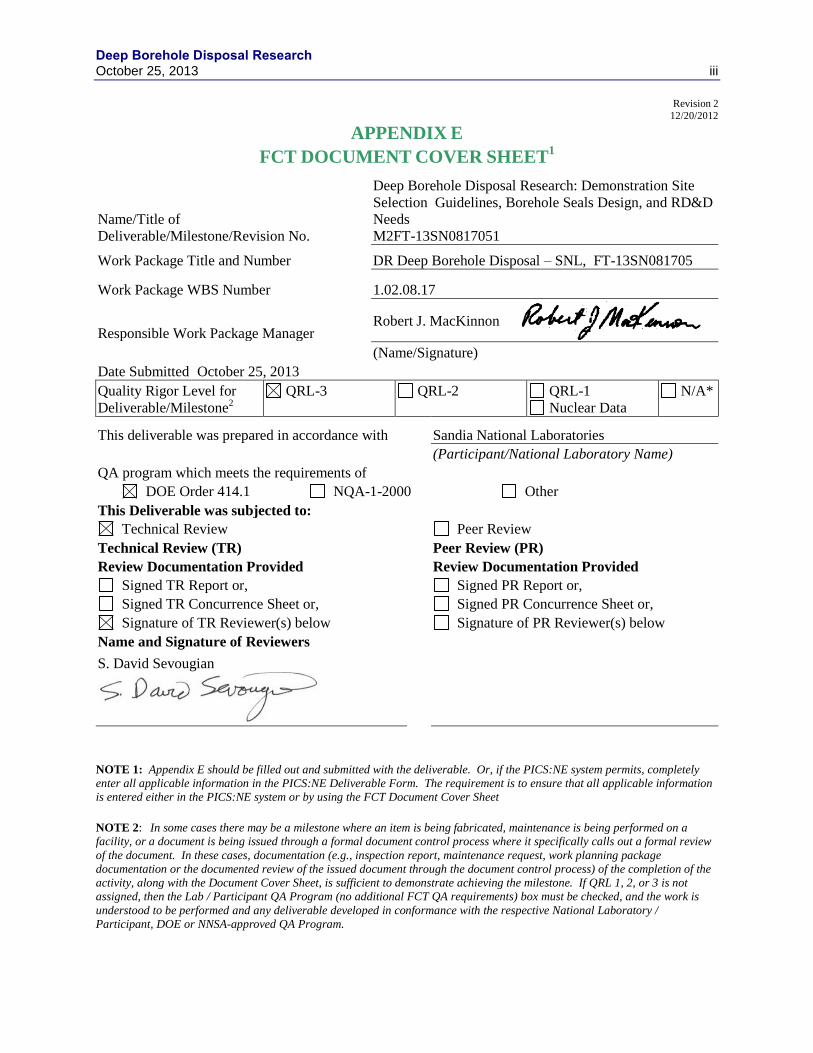
APPENDIX E
FCT DOCUMENT COVER SHEET1
NOTE 1: Appendix E should be filled out and submitted with the deliverable. Or, if the PICS:NE system permits, completely
enter all applicable information in the PICS:NE Deliverable Form. The requirement is to ensure that all applicable information
is entered either in the PICS:NE system or by using the FCT Document Cover Sheet
NOTE 2: In some cases there may be a milestone where an item is being fabricated, maintenance is being performed on a
facility, or a document is being issued through a formal document control process where it specifically calls out a formal review
of the document. In these cases, documentation (e.g., inspection report, maintenance request, work planning package
documentation or the documented review of the issued document through the document control process) of the completion of the
activity, along with the Document Cover Sheet, is sufficient to demonstrate achieving the milestone. If QRL 1, 2, or 3 is not
assigned, then the Lab / Participant QA Program (no additional FCT QA requirements) box must be checked, and the work is
understood to be performed and any deliverable developed in conformance with the respective National Laboratory /
Participant, DOE or NNSA-approved QA Program.
Name/Title of
Deliverable/Milestone/Revision No.
Deep Borehole Disposal Research: Demonstration Site
Selection Guidelines, Borehole Seals Design, and RD&D
Needs
M2FT-13SN0817051
Work Package Title and Number DR Deep Borehole Disposal – SNL, FT-13SN081705
Work Package WBS Number 1.02.08.17
Responsible Work Package Manager Robert J. MacKinnon
(Name/Signature)
Date Submitted October 25, 2013
Quality Rigor Level for
Deliverable/Milestone2
QRL-3 QRL-2 QRL-1
Nuclear Data
N/A*
This deliverable was prepared in accordance with Sandia National Laboratories
(Participant/National Laboratory Name)
QA program which meets the requirements of
DOE Order 414.1 NQA-1-2000 Other
This Deliverable was subjected to:
Technical Review Peer Review
Technical Review (TR) Peer Review (PR)
Review Documentation Provided Review Documentation Provided
Signed TR Report or, Signed PR Report or,
Signed TR Concurrence Sheet or, Signed PR Concurrence Sheet or,
Signature of TR Reviewer(s) below Signature of PR Reviewer(s) below
Name and Signature of Reviewers
S. David Sevougian

Deep Borehole Disposal Research iv October 25, 2013
This page intentionally left blank.
Deep Borehole Disposal Research October 25, 2013 v
EXECUTIVE SUMMARY
The U.S. Department of Energy has been investigating deep borehole disposal as one alternative
for the disposal of spent nuclear fuel and other radioactive waste forms, along with research and
development for mined repositories in salt, granite, and clay, as part of the used fuel disposition
(UFD) campaign. The deep borehole disposal concept is straightforward and consists of drilling
a borehole on the order of 5,000 m deep, emplacing waste canisters in the lower part of the
borehole, and sealing the upper part of the borehole with bentonite and concrete seals. A
reference design of the disposal system (Arnold et al. 2011a) includes emplacement of 400 waste
canisters in the lower 2,000 m of the borehole, seals and plugs in the uncased borehole for
1,500 m above the disposal zone, and standard borehole plugging in the cased upper 1,500 m of
the borehole. Safety of the disposal concept relies primarily on the great depth of burial, the
isolation provided by the deep natural geological environment, and the integrity of the borehole
seals. The DOE developed a research, development, and demonstration (RD&D) roadmap for
deep borehole disposal in FY12 (DOE 2012) that emphasized a full-scale demonstration project
around which research and development activities would be organized.
The overarching goal of deep borehole disposal research for FY13 is to advance the deep
borehole disposal technical basis needed to site and implement a full-scale demonstration
project. Given that identifying a demonstration project site is one of the first steps in a
demonstration project, a specific objective of the research is to establish technical and logistical
guidelines to be used in the evaluation of potential demonstration sites. An additional objective
is planning the experimental research program for investigation of alternative sealing methods,
including the time-dependent properties of candidate seal materials under a range of
environmental conditions. This objective is motivated by the recognition that the borehole seals
constitute the primary component of the engineered barrier system in the deep borehole disposal
concept. A final objective is to further establish the preliminary safety framework for this
disposal concept and for a deep borehole disposal demonstration project.
Selection of a site for a deep borehole disposal demonstration project would be informed by
numerous factors that fall into several categories, including technical factors, logistical/practical
factors, and sociopolitical factors. Numerous technical factors are potentially important to
drilling and construction of a deep borehole, successful completion of a deep borehole disposal
demonstration project, and the post-closure safety of the disposal system. Logistical factors for a
deep borehole disposal demonstration project are related to drilling activity in the petroleum
industry, geothermal industry, and, to a lesser extent, deep scientific drilling activity. Analysis
of social and political factors related to site selection is generally beyond the scope of this report,
but early engagement with local and regional stakeholders at any potential location, particularly
in the scientific and academic communities, would likely improve the chances of implementing a
demonstration project. Overall, the site selection strategy for the demonstration project aims to
maximize the probability of successfully completing the borehole, at a site with favorable
geological, hydrogeological, and geochemical conditions, within budgetary and schedule
constraints.
Deep Borehole Disposal Research vi October 25, 2013
A number of geological, hydrogeological, and geophysical factors have been evaluated that are
potentially relevant to successfully completing a deep borehole demonstration project and
demonstrating post-closure safety for a deep borehole disposal system:
Depth to crystalline basement – (less than 2,000 m favorable)
Crystalline basement lithology – (felsic intrusive rocks preferred)
Basement structural complexity – (faults, shear zones, and tectonic complexes
unfavorable)
Horizontal stress – (small differential in horizontal stress favorable)
Tectonic uplift – (low uplift rate favorable)
Geothermal heat flux – (low heat flux favorable)
Topographic relief and hydraulic gradient – (low regional topographic relief favorable)
Quaternary faults and volcanism – (Quaternary-age faulting and volcanism unfavorable)
Mineral resources potential – (Higher potential for mineral resources in crystalline
basement generally unfavorable)
Regarding logistical considerations for a demonstration project, deep drilling is now common
within the petroleum industry, but there are few examples where large-diameter wells (greater
than about 12 inches diameter) have been drilled in crystalline bedrock to depths of 4,000 to
5,000 meters (Beswick 2008). Although rigs large enough to drill a reference design borehole
are not common, there are at least seven drilling contractors in the US that have this capability.
These rigs are located in the western and southwestern US. Drilling support services, such as
completion and logging services, are available through companies that work with the petroleum
drilling sector. The supply chain within the U.S. is robust and it is expected that services and
supplies can be procured by competitive bid for each type of equipment or service.
The details of the legal and regulatory requirements for permitting a deep borehole disposal
demonstration project vary among states and for Federal versus private land; however, the
National Environmental Policy Act compliance framework provides guidance to inform the
decision on site selection. The project scope and duration are not of a magnitude that would
generally require an Environmental Impact Statement, so planning should be conducted for an
Environmental Assessment, which is considerably less rigorous than an Environmental Impact
Statement. Drilling, land, and water use permits are also generally subject to state regulation and
are routinely granted for other drilling operations in most states.
Key objectives of the borehole seals effort are to use ex situ testing to: 1) demonstrate
performance of bentonite seals; 2) measure brine/cement impact on bentonite permeability; 3)
build the technical basis for rock-welding of seals, and 4) identify (any) effects of waste package
corrosion on seals. Avoiding bentonite shrinkage is one key to assuring low seal permeabilities.
Another is demonstrating that cement will not undergo large-scale volume changes over several
thousand years. Bentonite volume is reduced by high ionic strength and/or the introduction of
divalent cations, such as Ca+2
, Mg+2
, and Fe+2
(produced during the anoxic corrosion of steel
casing).
Deep Borehole Disposal Research October 25, 2013 vii
Research on alternative seals has been directed at the main seals emplaced above the waste
disposal zone and at the sealing and support matrix that surrounds the waste canisters. Rock
welding in the main seals zone by partial melting and recrystallization of crushed rock within the
borehole and in the surrounding host rock would produce a robust seal of the borehole and the
excavation damage zone. A rock welding seal would be highly durable because, unlike bentonite
and cement, it would be in chemical and mineralogical equilibrium with the physical and
chemical conditions at depth. Modeling work indicates that a rock melt volume of sufficient size
to form such a seal could be generated with an electrical resistance heater, with a modest power
requirement (about 11 kW) and in a reasonable time. The shape and size of the rock weld can be
controlled by varying the length and diameter of the heater. Materials such as bentonite, cement
grout, and low melting temperature metal alloys have been investigated as sealing and support
matrices; however, challenges remain concerning the operational emplacement and suitability of
these materials. Research is continuing to address these challenges and to evaluate candidate
formulations with regard to rheology, setting or thickening time, hardening and mechanical
properties, geochemical reactions, and durability.
The technical bases for the safety framework have been updated or reevaluated with regard to
thermally driven groundwater flow, nuclear criticality and operational safety. Large-scale
thermal hydrologic modeling has been updated to incorporate more realistic geological and
hydrogeological conditions, and to provide input to an updated performance assessment (PA)
model of the deep borehole disposal system. Thermal-hydrologic simulations indicate vertical
upward groundwater flux in the borehole and surrounding disturbed rock zone of the waste
disposal zone for an extended period of time. Significant, but lower vertical flux also occurs
above the waste disposal zone through potentially degraded seals and/or the surrounding
disturbed rock zone. Criticality safety is not a design, operation or permitting issue for
conducting the demonstration project, because the use of actual nuclear fuel is not anticipated.
A systematic approach to the prioritization of RD&D activities uses information from several
previous PA analyses and from the updated PA model documented in this report. The basis of
this prioritization is primarily the post-closure safety of the deep borehole disposal system. A
synthesis of existing PA analyses has identified the more important processes with regard to
disposal system safety and the characterization activities necessary to help reduce uncertainties
associated with these processes.
The updated deep borehole disposal PA model incorporates the simulated vertical flow rates
from the updated thermal-hydrologic modeling and includes a significant conceptual
improvement relative to previous PA modeling through the implementation of lateral
radionuclide diffusion between the borehole and the surrounding rock. The updated PA model
for a single borehole is implemented in the GoldSim® software code. Base case simulations
with the updated PA model demonstrate lateral diffusion of radionuclides from the borehole into
the surrounding bedrock and indicate no releases of radionuclides to the biosphere within
1,000,000 years of deep borehole disposal. Sensitivity analyses for a case in which the vertical
groundwater flow rates are increased by a factor of 10 and the waste form degradation rate is
increased by a factor of 100 show a negligibly small peak mean annual dose at 1,000,000 years,
primarily from releases of I-129.
The primary objective of the safety framework study is to confirm the safety of disposing SNF
and/or other forms of radioactive waste in a deep borehole disposal system. The initial safety
framework documented as a stand-alone report in Appendix A focuses on a generic safety
Deep Borehole Disposal Research viii October 25, 2013
framework for the deep borehole disposal concept. This safety framework is developed using
information collected and analyses conducted prior to and during the course of the deep borehole
demonstration.
The Deep Borehole Disposal Consortium was established through the course of two meetings in
Albuquerque, New Mexico in 2011 and 2013 and consists of industrial and academic partners
that were assembled to enhance efforts to complete a deep borehole demonstration. A
Memorandum of Understanding (MOU) was signed to enable collaboration between the parties
to “promote the construction and operation of a deep borehole demonstration to evaluate the
feasibility of long-term disposal of nuclear waste.” Members having signed the MOU include
Areva, CH2M-Hill, DOSECC Exploration Services, Massachusetts Institute of Technology,
Olympic Research, Sandia National Laboratories, University of Sheffield, and URS.
Important conclusions from this milestone report include the following:
Evaluation of technical and logistical site selection guidelines indicates that there are
large areas within the conterminous U.S. that are favorable for the location of a deep
borehole disposal demonstration project, in particular, and long-term deep borehole
disposal, in general.
Specific requirements for experimental evaluations of bentonite and cement as seals
materials have been identified.
Numerical modeling of rock melting and the formation of rock welding seals indicates
that this is a potentially viable alternative borehole sealing method.
Higher priority science and engineering R&D activities for a deep borehole
demonstration project have been identified, based on importance to post-closure safety.
Updated thermal-hydrologic modeling of a multiple-borehole disposal system and
updated PA modeling that includes lateral diffusion from the borehole indicate no
radionuclide releases to the biosphere within 1,000,000 years for the undisturbed base-
case scenario.
A Deep Borehole Disposal Consortium consisting of Sandia National Laboratories,
industrial, and academic partners was established to “promote the construction and
operation of a deep borehole demonstration to evaluate the feasibility of long-term
disposal of nuclear waste.”
A generic safety case study has been documented and indicates that a defensible safety
case can be developed for deep borehole disposal of high-level nuclear waste, assuming
that the demonstration project confirms the technical bases underlying the deep borehole
disposal concept.

Deep Borehole Disposal Research October 25, 2013 ix
CONTENTS
CONTENTS ................................................................................................................................... ix
1. INTRODUCTION ..................................................................................................................1
1.1 Background ...................................................................................................................1
1.2 Objectives and Scope ....................................................................................................2
2. DEMONSTRATION SITE SELECTION GUIDELINES ....................................................4
2.1 Demonstration Site Selection Strategy .........................................................................4
2.2 Relationship of Site Selection to the Disposal Safety Framework ...............................5 2.2.1 Components of Safety Case and Relationship to Site Selection .......................5 2.2.2 Summary of Technical Site Selection Guidelines Supporting the
Safety Framework .............................................................................................7
2.3 Technical Selection Guidelines ..................................................................................10 2.3.1 Depth to Crystalline Basement .......................................................................10 2.3.2 Crystalline Basement Lithology .....................................................................13 2.3.3 Basement Structural Complexity ....................................................................21 2.3.4 Horizontal Stress .............................................................................................22 2.3.5 Tectonic Uplift ................................................................................................26 2.3.6 Geothermal Heat Flux .....................................................................................28 2.3.7 Topographic Relief and Hydraulic Gradient ..................................................31 2.3.8 Quaternary Faults and Volcanism ..................................................................33 2.3.9 Mineral Resources Potential ...........................................................................34
2.4 Logistical and Other Selection Guidelines .................................................................36 2.4.1 Drilling Contractor Availability .....................................................................36 2.4.2 Drilling Support Services Availability ...........................................................37 2.4.3 Permitting Considerations ..............................................................................38
3. BOREHOLE SEALS AND WASTE EMPLACEMENT ....................................................41
3.1 Seal Materials Testing Strategy ..................................................................................41
3.2 Review of Bentonite and Cement Seals Stability .......................................................41
3.3 Alternative Seals Research .........................................................................................42 3.3.1 Borehole Sealing by Rock Welding ...............................................................43 3.3.2 Waste Package Sealing and Waste Package Support Matrices ......................47
3.4 Waste Package Deployment .......................................................................................51 3.4.1 Emplacement Rates ........................................................................................52 3.4.2 Emplacement Mechanisms .............................................................................53
3.5 Seals Demonstration Testing Plan ..............................................................................55
4. SAFETY FRAMEWORK AND RD&D NEEDS ................................................................57
4.1 Identification of RD&D Needs for Demonstration of Safety .....................................57
4.2 Technical Basis for Prioritization in the Safety Framework ......................................59 4.2.1 Site-Scale Thermal-Hydrologic Effects ..........................................................59
Deep Borehole Disposal Research x October 25, 2013
4.2.2 Borehole-Scale Thermal-Hydrologic Effects .................................................69 4.2.3 Nuclear Criticality ..........................................................................................70 4.2.4 Operational Safety Assessment ......................................................................71
4.3 Analysis of Performance Assessment Results ............................................................72 4.3.1 Deep Borehole Disposal of High-Level Radioactive Waste Study ................72 4.3.2 Deep Borehole Seals Study ............................................................................73 4.3.3 Generic Disposal System Modeling Fiscal Year 2011 Progress Report ........75 4.3.4 Generic Deep Geologic Disposal Safety Case (Freeze et al. 2013) ...............78 4.3.5 Updated Performance Assessment Model ......................................................81 4.3.6 Demonstration of Deep Borehole Disposal Post-Closure Safety ...................83
4.4 Updated Performance Assessment Model ..................................................................84 4.4.1 Performance Assessment Model Setup ..........................................................84 4.4.2 Performance Assessment Analysis Results ....................................................87 4.4.3 Summary and Discussion .............................................................................134
4.5 Summary Safety Case for Deep Borehole Disposal .................................................134
5. DEMONSTRATION PROJECT PLANNING ..................................................................137
5.1 Deep Borehole Disposal Consortium .......................................................................137
6. SUMMARY AND CONCLUSIONS .................................................................................138
7. REFERENCES ...................................................................................................................143
Appendix A. Draft Safety Case for Deep Borehole Disposal of High-Level
Radioactive Waste .............................................................................................................. A-i
Deep Borehole Disposal Research October 25, 2013 xi
FIGURES
Figure 2-1. Depth to crystalline basement outcrops in the continental U.S. (Perry 2013).
Depth of 2,000 m shown with the bold contour line and crystalline basement
outcrops shown in red. ................................................................................................... 11
Figure 2-2. Depth to crystalline basement outcrops in the continental U.S. (Perry 2013).
Depth of 2,000 m or less shown with brown shading and crystalline basement
outcrops shown in red. ................................................................................................... 13
Figure 2-3. Terrane map of the Precambrian basement of South Dakota (from
McCormick 2010) .......................................................................................................... 17
Figure 2-4. Geology of the Precambrian surface of Iowa and surrounding area (from
Anderson 2006) .............................................................................................................. 18
Figure 2-5. Map of the first horizontal derivative of the gravity data for South Dakota,
with hillshade (from McCormick 2010) ........................................................................ 19
Figure 2-6. Residual aeromagnetic map of Kansas, second order regional trend removed
(from Xia et al. 1995)..................................................................................................... 20
Figure 2-7. Precambrian basement structure map and aeromagnetic data. (Perry, 2013,
source: Sims et al. 2008) ................................................................................................ 22
Figure 2-8. Generalized geologic map of the midcontinent rift system. (from Van Schmus
and Hinze, 1985) ............................................................................................................ 23
Figure 2-9. Cross section of a borehole wall showing two diametrically opposed
breakouts with major and minor horizontal in situ stress axis displayed. (source:
Lee and Haimson, 1993). ............................................................................................... 24
Figure 2-10. Horizontal stress data for the United States compiled by the World Stress
Map Project (source: Heidbach et al, 2008). .................................................................. 25
Figure 2-11. Generalized stress provinces for the United States (source: Zoback and
Zoback 1989). ................................................................................................................ 26
Figure 2-12. The extent of the ice sheet margins in North America at the last glacial
maximum (LGM) (source: Dyke et al. 2002). ............................................................... 28
Figure 2-13. Geothermal heat flow in the continental U.S. (source: SMU Geothermal
Laboratory 2004). .......................................................................................................... 29
Figure 2-14. Estimated geothermal gradient in the continental U.S. (source: SMU
Geothermal Laboratory 2004). ....................................................................................... 30
Figure 2-15. Estimated temperature at 4 km depth in the continental U.S. (source: SMU
Geothermal Laboratory 2004) ........................................................................................ 30
Figure 2-16. Topographic slope in the continental U.S. (Perry 2013) .......................................... 32
Figure 2-17. Quaternary faults (blue) and Plio-Quaternary volcanic fields (black) in the
continental U.S. (source: USGS 2006 and Garrity and Soller 2009)............................. 34
Deep Borehole Disposal Research xii October 25, 2013
Figure 3-1. Gold bag (left) and gasket confined closure reactor (right) – Courtesy, Florie
Caporuscio, Los Alamos National Laboratory. ............................................................. 42
Figure 3-2. Peak temperatures generated in and around a 0.43 m (a) and a 0.56 m (b)
diameter borehole by a 2 m long, 0.172 m diameter heater with a power output
of 240 kWm-3
(a) and 0.224 m diameter with a power output of 150 kWm-3
(b)
(see text). Isotherms are at 100°C intervals with the 700ºC isotherm (~ granite
solidus) in red. ................................................................................................................ 45
Figure 3-3. Evolution of temperature at 6 points around a single 4.6 m long waste
package, 0.36 m in diameter, containing one 25 year old used PWR fuel
assembly with a burn up of 55 GWd/MT. Borehole diameter = 0.56 m; ambient
temperature = 80°C. Solid lines are for the outer surface of the container;
dashed lines are for the borehole wall. Blue = Top of the package; Red = Middle
of the package; Green = Bottom of the package. ........................................................... 49
Figure 3-4. Evolution of temperature at 6 points around a batch of 5 waste packages the
same as in Figure 3-3 inserted at 1 day intervals. Borehole diameter = 0.56 m;
ambient temperature = 80ºC. Solid lines are for the outer surface of the
containers; dashed lines are for the borehole wall. Blue = Top of the batch; Red
= Middle of the batch; Green = Bottom of the batch. ................................................... 50
Figure 4-1. Numerical grid for the thermal-hydrologic model from perspective view (a)
and expanded top view of the borehole array (b). ......................................................... 61
Figure 4-2. Permeability, thermal conductivity, and lithology as functions of depth in the
model. Permeability is shown with the black curve and thermal conductivity
with the blue curve. The waste disposal zone depth is shown for reference on
the middle right of the graph. ......................................................................................... 62
Figure 4-3. Simulated ambient temperature, salinity, and lithology as functions of depth
in the model. Simulated ambient temperature is shown with the black curve and
salinity with the red curve. The waste disposal zone depth is shown for
reference on the middle right of the graph. .................................................................... 63
Figure 4-4. Simulated temperature at 4,000 m depth and at 0.8 m radius from the
borehole centerline for the central borehole in arrays of varying numbers of
boreholes. Results are shown for the disposal of used nuclear fuel rods. ..................... 65
Figure 4-5. Simulated vertical groundwater flux at varying depths in the sealed borehole
and disturbed rock zone for the central borehole in an array of 81 boreholes.
Results are shown for the disposal of used nuclear fuel rods. ....................................... 66
Figure 4-6. Simulated vertical groundwater flux in the sealed borehole and disturbed rock
zone at 3,000 m depth for the central borehole in arrays of varying numbers of
boreholes. Results are shown for the disposal of used nuclear fuel rods. ..................... 67
Figure 4-7. Simulated vertical groundwater flux in the sealed borehole and disturbed rock
zone at 3,000 m depth for the central borehole an array of 81 boreholes for
alternative models of permeability as a function of depth. Results are shown for
the disposal of used nuclear fuel rods. ........................................................................... 68
Deep Borehole Disposal Research October 25, 2013 xiii
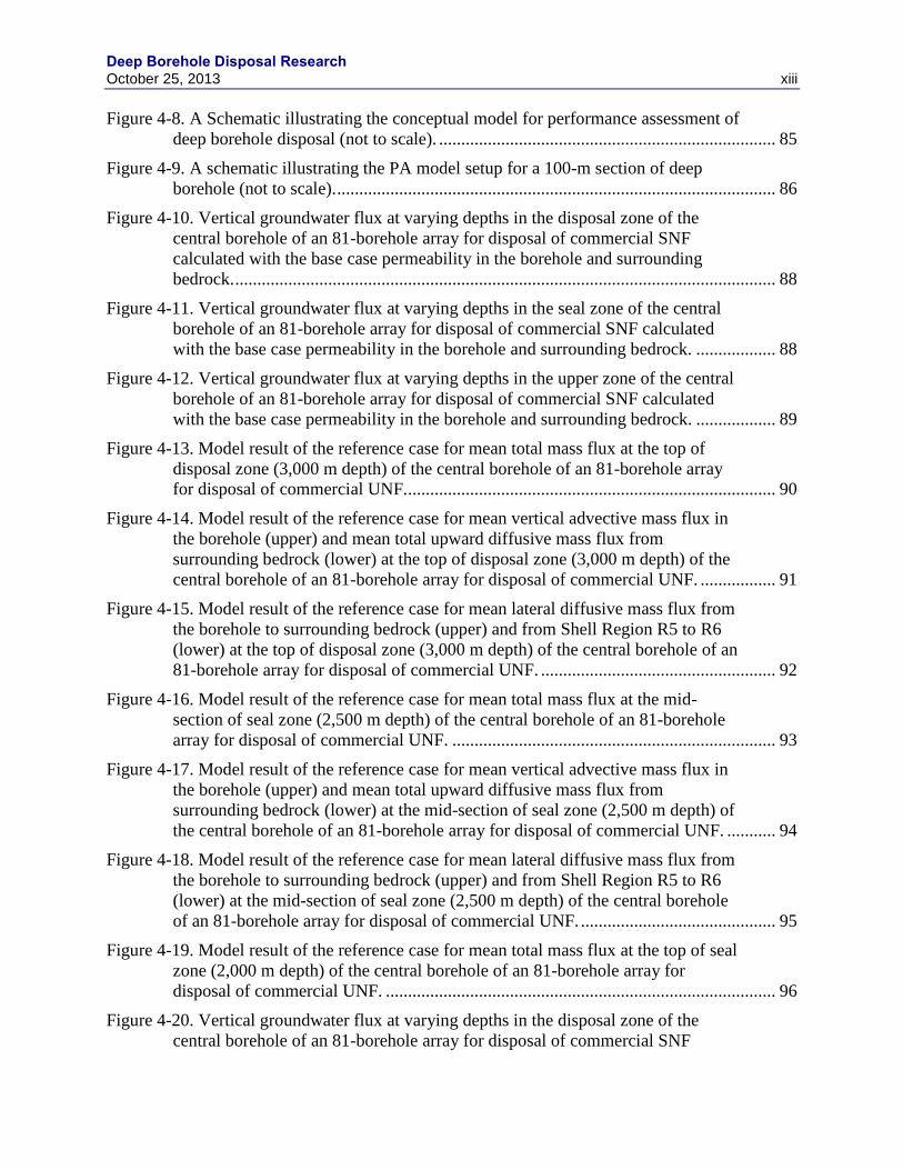
Figure 4-8. A Schematic illustrating the conceptual model for performance assessment of
deep borehole disposal (not to scale). ............................................................................ 85
Figure 4-9. A schematic illustrating the PA model setup for a 100-m section of deep
borehole (not to scale). ................................................................................................... 86
Figure 4-10. Vertical groundwater flux at varying depths in the disposal zone of the
central borehole of an 81-borehole array for disposal of commercial SNF
calculated with the base case permeability in the borehole and surrounding
bedrock. .......................................................................................................................... 88
Figure 4-11. Vertical groundwater flux at varying depths in the seal zone of the central
borehole of an 81-borehole array for disposal of commercial SNF calculated
with the base case permeability in the borehole and surrounding bedrock. .................. 88
Figure 4-12. Vertical groundwater flux at varying depths in the upper zone of the central
borehole of an 81-borehole array for disposal of commercial SNF calculated
with the base case permeability in the borehole and surrounding bedrock. .................. 89
Figure 4-13. Model result of the reference case for mean total mass flux at the top of
disposal zone (3,000 m depth) of the central borehole of an 81-borehole array
for disposal of commercial UNF.................................................................................... 90
Figure 4-14. Model result of the reference case for mean vertical advective mass flux in
the borehole (upper) and mean total upward diffusive mass flux from
surrounding bedrock (lower) at the top of disposal zone (3,000 m depth) of the
central borehole of an 81-borehole array for disposal of commercial UNF. ................. 91
Figure 4-15. Model result of the reference case for mean lateral diffusive mass flux from
the borehole to surrounding bedrock (upper) and from Shell Region R5 to R6
(lower) at the top of disposal zone (3,000 m depth) of the central borehole of an
81-borehole array for disposal of commercial UNF. ..................................................... 92
Figure 4-16. Model result of the reference case for mean total mass flux at the mid-
section of seal zone (2,500 m depth) of the central borehole of an 81-borehole
array for disposal of commercial UNF. ......................................................................... 93
Figure 4-17. Model result of the reference case for mean vertical advective mass flux in
the borehole (upper) and mean total upward diffusive mass flux from
surrounding bedrock (lower) at the mid-section of seal zone (2,500 m depth) of
the central borehole of an 81-borehole array for disposal of commercial UNF. ........... 94
Figure 4-18. Model result of the reference case for mean lateral diffusive mass flux from
the borehole to surrounding bedrock (upper) and from Shell Region R5 to R6
(lower) at the mid-section of seal zone (2,500 m depth) of the central borehole
of an 81-borehole array for disposal of commercial UNF. ............................................ 95
Figure 4-19. Model result of the reference case for mean total mass flux at the top of seal
zone (2,000 m depth) of the central borehole of an 81-borehole array for
disposal of commercial UNF. ........................................................................................ 96
Figure 4-20. Vertical groundwater flux at varying depths in the disposal zone of the
central borehole of an 81-borehole array for disposal of commercial SNF
Deep Borehole Disposal Research xiv October 25, 2013
calculated with the alternative permeability function of Stober and Bucher
(2007) in the borehole and surrounding bedrock. .......................................................... 97
Figure 4-21. Vertical groundwater flux at varying depths in the seal zone of the central
borehole of an 81-borehole array for disposal of commercial SNF calculated
with the alternative permeability function of Stober and Bucher (2007) in the
borehole and surrounding bedrock................................................................................. 98
Figure 4-22. Vertical groundwater flux at varying depths in the upper zone of the central
borehole of an 81-borehole array for disposal of commercial SNF calculated
with the alternative permeability function of Stober and Bucher (2007) in the
borehole and surrounding bedrock................................................................................. 98
Figure 4-23. Model result of the alternative permeability case for mean total mass flux at
the top of disposal zone (3,000 m depth) of the central borehole of an 81-
borehole array for disposal of commercial UNF. .......................................................... 99
Figure 4-24. Model result of the alternative permeability case for mean vertical advective
mass flux in the borehole (upper) and mean total upward diffusive mass flux
from surrounding bedrock (lower) at the top of disposal zone (3,000 m depth) of
the central borehole of an 81-borehole array for disposal of commercial UNF. ......... 100
Figure 4-25. Model result of the alternative permeability case for mean lateral diffusive
mass flux from the borehole to surrounding bedrock (left) and from Shell
Region R5 to R6 (right) at the top of disposal zone (3,000 m depth) of the
central borehole of an 81-borehole array for disposal of commercial UNF. ............... 101
Figure 4-26. Model result of the alternative permeability case for mean total mass flux at
the mid-section of seal zone (2,500 m depth) of the central borehole of an 81-
borehole array for disposal of commercial UNF. ........................................................ 102
Figure 4-27. Model result of the alternative permeability case for mean total mass flux at
the top of seal zone (2,000 m depth) of the central borehole of an 81-borehole
array for disposal of commercial UNF. ....................................................................... 103
Figure 4-28. Model result of the high groundwater flux case for mean total mass flux at
the top of disposal zone (3,000 m depth) of the central borehole of an 81-
borehole array for disposal of commercial UNF. ........................................................ 104
Figure 4-29. Model result of the high groundwater flux case for mean vertical advective
mass flux in the borehole (upper) and mean total upward diffusive mass flux
from surrounding bedrock (lower) at the top of disposal zone (3,000 m depth) of
the central borehole of an 81-borehole array for disposal of commercial UNF. ......... 105
Figure 4-30. Model result of the high groundwater flux case for mean lateral diffusive
mass flux from the borehole to surrounding bedrock (upper) and from Shell
Region R5 to R6 (lower) at the top of disposal zone (3,000 m depth) of the
central borehole of an 81-borehole array for disposal of commercial UNF. ............... 106
Figure 4-31. Model result of the high groundwater flux case for mean total mass flux at
the mid-section of seal zone (2,500 m depth) of the central borehole of an 81-
borehole array for disposal of commercial UNF. ........................................................ 107

Deep Borehole Disposal Research October 25, 2013 xv
Figure 4-32. Model result of the high groundwater flux case for mean vertical advective
mass flux in the borehole (upper) and mean total upward diffusive mass flux
from surrounding bedrock (lower) at the mid-section of seal zone (2,500 m
depth) of the central borehole of an 81-borehole array for disposal of
commercial UNF. ......................................................................................................... 108
Figure 4-33. Model result of the high groundwater flux case for mean lateral diffusive
mass flux from the borehole to surrounding bedrock (left) and from Shell
Region R5 to R6 (right) at the mid-section of seal zone (2,500 m depth) of the
central borehole of an 81-borehole array for disposal of commercial UNF. ............... 109
Figure 4-34. Model result of the high groundwater flux case for mean total mass flux at
the top of seal zone (2,000 m depth) of the central borehole of an 81-borehole
array for disposal of commercial UNF. ....................................................................... 110
Figure 4-35. Model result of the high groundwater flux case for mean vertical advective
mass flux in the borehole (upper) and mean total upward diffusive mass flux
from surrounding bedrock (lower) at the top of seal zone (2,0000 m depth) of
the central borehole of an 81-borehole array for disposal of commercial UNF. ......... 111
Figure 4-36. Model result of the high groundwater flux case for mean lateral diffusive
mass flux from the borehole to surrounding bedrock (upper) and from Shell
Region R5 to R6 (lower) at the top of seal zone (2,000 m depth) of the central
borehole of an 81-borehole array for disposal of commercial UNF. ........................... 112
Figure 4-37. Model result of the high groundwater flux case for mean total mass flux at
the mid-section of upper zone (1,000 m depth) of the central borehole of an 81-
borehole array for disposal of commercial UNF. ........................................................ 113
Figure 4-38. Model result of the high groundwater flux case for mean total mass flux at
the top of upper zone of the central borehole of an 81-borehole array for
disposal of commercial UNF. ...................................................................................... 114
Figure 4-39. Model result of the high groundwater flux case for mean annual dose by
radionuclides released from the central borehole of an 81-borehole array for
disposal of commercial UNF. ...................................................................................... 114
Figure 4-40. Model result of the enhanced SNF degradation case for mean total mass flux
at the top of disposal zone (3,000 m depth) of the central borehole of an 81-
borehole array for disposal of commercial UNF. ........................................................ 115
Figure 4-41. Model result of the enhanced SNF degradation case for mean vertical
advective mass flux in the borehole (upper) and mean total upward diffusive
mass flux from surrounding bedrock (lower) at the top of disposal zone (3,000
m depth) of the central borehole of an 81-borehole array for disposal of
commercial UNF. ......................................................................................................... 116
Figure 4-42. Model result of the enhanced SNF degradation case for mean lateral
diffusive mass flux from the borehole to surrounding bedrock (upper) and from
Shell Region R5 to R6 (lower) at the top of disposal zone (3,000 m depth) of the
central borehole of an 81-borehole array for disposal of commercial SNF. ................ 117
Deep Borehole Disposal Research xvi October 25, 2013
Figure 4-43. Model result of the enhanced SNF degradation case for mean total mass flux
at the mid-section of seal zone (2,500 m depth) of the central borehole of an 81-
borehole array for disposal of commercial SNF. ......................................................... 118
Figure 4-44. Model result of the enhanced SNF degradation case for mean vertical
advective mass flux in the borehole (upper) and mean total upward diffusive
mass flux from surrounding bedrock (lower) at the mid-section of seal zone
(2,500 m depth) of the central borehole of an 81-borehole array for disposal of
commercial SNF. ......................................................................................................... 119
Figure 4-45. Model result of the enhanced SNF degradation case for mean lateral
diffusive mass flux from the borehole to surrounding bedrock (upper) and from
Shell Region R5 to R6 (lower) at the mid-section of seal zone (2,500 m depth)
of the central borehole of an 81-borehole array for disposal of commercial SNF. ..... 120
Figure 4-46. Model result of the enhanced SNF degradation case for mean total mass flux
at the top of seal zone (2,000 m depth) of the central borehole of an 81-borehole
array for disposal of commercial SNF. ........................................................................ 121
Figure 4-47. Model result of the combined high groundwater flux and enhanced SNF
degradation case for mean total mass flux at the top of disposal zone (3,000 m
depth) of the central borehole of an 81-borehole array for disposal of
commercial SNF. ......................................................................................................... 122
Figure 4-48. Model result of the combined high groundwater flux and enhanced SNF
degradation case for mean vertical advective mass flux in the borehole (upper)
and mean total upward diffusive mass flux from surrounding bedrock (lower) at
the top of disposal zone (3,000 m depth) of the central borehole of an 81-
borehole array for disposal of commercial SNF. ......................................................... 123
Figure 4-49. Model result of the combined high groundwater flux and enhanced SNF
degradation case for mean lateral diffusive mass flux from the borehole to
surrounding bedrock (upper) and from Shell Region R5 to R6 (lower) at the top
of disposal zone (3,000 m depth) of the central borehole of an 81-borehole array
for disposal of commercial SNF. ................................................................................. 124
Figure 4-50. Model result of the combined high groundwater flux and enhanced SNF
degradation case for mean total mass flux at the mid-section of seal zone (2,500
m depth) of the central borehole of an 81-borehole array for disposal of
commercial SNF. ......................................................................................................... 125
Figure 4-51. Model result of the combined high groundwater flux and enhanced SNF
degradation case for mean vertical advective mass flux in the borehole (upper)
and mean total upward diffusive mass flux from surrounding bedrock (lower) at
the mid-section of seal zone (2,5000 m depth) of the central borehole of an 81-
borehole array for disposal of commercial SNF. ......................................................... 126
Figure 4-52. Model result of the combined high groundwater flux and enhanced SNF
degradation case for mean lateral diffusive mass flux from the borehole to
surrounding bedrock (upper) and from Shell Region R5 to R6 (lower) at the

Deep Borehole Disposal Research October 25, 2013 xvii
mid-section of seal zone (2,500 m depth) of the central borehole of an 81-
borehole array for disposal of commercial SNF. ......................................................... 127
Figure 4-53. Model result of the combined high groundwater flux and enhanced SNF
degradation case for mean total mass flux at the top of seal zone (2,000 m
depth) of the central borehole of an 81-borehole array for disposal of
commercial SNF. ......................................................................................................... 128
Figure 4-54. Model result of the combined high groundwater flux and enhanced SNF
degradation case for mean vertical advective mass flux in the borehole (upper)
and mean total upward diffusive mass flux from surrounding bedrock (lower) at
the top of seal zone (2,0000 m depth) of the central borehole of an 81-borehole
array for disposal of commercial SNF. ........................................................................ 129
Figure 4-55. Model result of the combined high groundwater flux and enhanced SNF
degradation case for mean lateral diffusive mass flux from the borehole to
surrounding bedrock (upper) and from Shell Region R5 to R6 (lower) at the top
of seal zone (2,000 m depth) of the central borehole of an 81-borehole array for
disposal of commercial SNF. ....................................................................................... 130
Figure 4-56. Model result of the combined high groundwater flux and enhanced SNF
degradation case for mean total mass flux at the mid-section of upper zone
(1,000 m depth) of the central borehole of an 81-borehole array for disposal of
commercial UNF. ......................................................................................................... 131
Figure 4-57. Model result of the combined high groundwater flux and enhanced SNF
degradation case for mean vertical advective mass flux in the borehole (upper)
and mean total upward diffusive mass flux from surrounding bedrock (lower) at
the mid-section of upper zone (1,000 m depth) of the central borehole of an 81-
borehole array for disposal of commercial SNF. ......................................................... 132
Figure 4-58. Model result of the combined high groundwater flux and enhanced SNF
degradation case for mean total mass flux at the top of upper zone of the central
borehole of an 81-borehole array for disposal of commercial SNF............................. 133
Figure 4-59. Model result of the combined high groundwater flux and enhanced SNF
degradation case for mean annual dose by radionuclides released from the
central borehole of an 81-borehole array for disposal of commercial SNF. ................ 133
Deep Borehole Disposal Research xviii October 25, 2013
TABLES
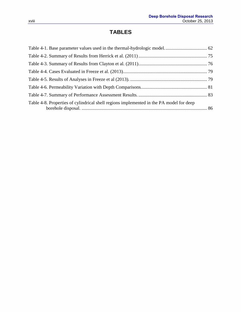
Table 4-1. Base parameter values used in the thermal-hydrologic model. ................................... 62
Table 4-2. Summary of Results from Herrick et al. (2011) .......................................................... 75
Table 4-3. Summary of Results from Clayton et al. (2011) .......................................................... 76
Table 4-4. Cases Evaluated in Freeze et al. (2013)....................................................................... 79
Table 4-5. Results of Analyses in Freeze et al (2013). ................................................................. 79
Table 4-6. Permeability Variation with Depth Comparisons........................................................ 81
Table 4-7. Summary of Performance Assessment Results. .......................................................... 83
Table 4-8. Properties of cylindrical shell regions implemented in the PA model for deep
borehole disposal. .......................................................................................................... 86
Deep Borehole Disposal Research October 25, 2013 xix
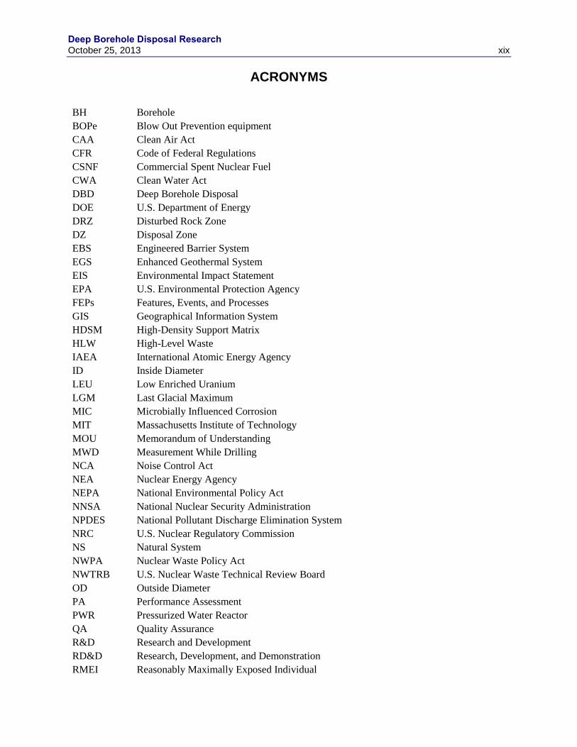
ACRONYMS
BH Borehole
BOPe Blow Out Prevention equipment
CAA Clean Air Act
CFR Code of Federal Regulations
CSNF Commercial Spent Nuclear Fuel
CWA Clean Water Act
DBD Deep Borehole Disposal
DOE U.S. Department of Energy
DRZ Disturbed Rock Zone
DZ Disposal Zone
EBS Engineered Barrier System
EGS Enhanced Geothermal System
EIS Environmental Impact Statement
EPA U.S. Environmental Protection Agency
FEPs Features, Events, and Processes
GIS Geographical Information System
HDSM High-Density Support Matrix
HLW High-Level Waste
IAEA International Atomic Energy Agency
ID Inside Diameter
LEU Low Enriched Uranium
LGM Last Glacial Maximum
MIC Microbially Influenced Corrosion
MIT Massachusetts Institute of Technology
MOU Memorandum of Understanding
MWD Measurement While Drilling
NCA Noise Control Act
NEA Nuclear Energy Agency
NEPA National Environmental Policy Act
NNSA National Nuclear Security Administration
NPDES National Pollutant Discharge Elimination System
NRC U.S. Nuclear Regulatory Commission
NS Natural System
NWPA Nuclear Waste Policy Act
NWTRB U.S. Nuclear Waste Technical Review Board
OD Outside Diameter
PA Performance Assessment
PWR Pressurized Water Reactor
QA Quality Assurance
R&D Research and Development
RD&D Research, Development, and Demonstration
RMEI Reasonably Maximally Exposed Individual

Deep Borehole Disposal Research xx October 25, 2013
RW Reprocessed Waste
SCC Stress Corrosion Cracking
SMU Southern Methodist University
SNF Spent Nuclear Fuel
SSCs Structures, Systems, and Components
SSM Sealing and Support Matrix
SZ Saturated Zone
TH Thermal-Hydrologic
TRU Transuranic
UFD Used Fuel Disposition
UFDC Used Fuel Disposition Campaign
UNF Used Nuclear Fuel
USGS U.S. Geological Survey
UZ Unsaturated Zone
WIPP Waste Isolation Pilot Plant
Deep Borehole Disposal Research October 25, 2013 1
1. INTRODUCTION
1.1 Background
Deep borehole disposal (DBD) of high-level radioactive waste has been given consideration for
geological isolation for many years, including original evaluations of nuclear waste disposal
options by the U.S. National Academy of Sciences in 1957 (NAS 1957). Efforts by the United
States and the international community over the last half-century toward disposal of high-level
waste (HLW) and spent nuclear fuel (SNF) have primarily focused on mined repositories.
Nonetheless, evaluations of deep borehole disposal have periodically continued in several
countries (O’Brien et al. 1979; Woodward and Clyde Consultants 1983; Juhlin and Sandstedt
1989; Heiken et al. 1996; Nirex 2004; Anderson 2004; Gibb et al. 2008a). An updated
conceptual evaluation of deep borehole disposal of SNF and a preliminary performance
assessment have also been completed (Brady et al. 2009). A reference design and operations
were developed for deep borehole disposal of SNF using available drilling technology by Arnold
et al. (2011a). Site characterization methods were analyzed using basic performance assessment
methodology and were described in Vaughn et al. (2012a). These studies have identified no
fundamental flaws regarding safety or implementation of the deep borehole disposal concept.
The reference deep borehole disposal concept is straightforward and consists of drilling a
borehole on the order of 5,000 m deep, emplacing waste canisters in the lower part of the
borehole, and sealing the upper part of the borehole with bentonite and concrete seals. A
reference design of the disposal system (Arnold et al. 2011a) includes emplacement of 400 waste
canisters in the lower 2,000 m of the borehole, seals and plugs in the uncased borehole for
1,500 m above the disposal zone, and standard borehole plugging in the upper 1,500 m of the
borehole. Safety of the disposal concept relies primarily on the great depth of burial, the
isolation provided by the deep natural geological environment, and the integrity of the borehole
seals. In contrast, mined geological repositories, with the possible exception of those located in
extensive salt or argillaceous formations, rely on engineered systems, such as waste canisters
and/or buffer material, to a greater degree.
Factors suggesting that the deep borehole disposal concept is viable and safe have been
summarized previously in Brady et al. (2009) and Arnold et al. (2011a). Crystalline basement
rocks are relatively common in stable continental regions, either at the surface or within 2,000 m
depth. Existing drilling technology should permit the reliable construction of sufficiently large
diameter boreholes to a depth of 5,000 m, although this remains to be demonstrated. Total costs
for a deep borehole disposal system for SNF, including drilling, casing, borehole completion,
waste canister fabrication and loading, emplacement, and borehole sealing have been estimated
at about $US 40 million per borehole (Arnold et al., 2011a). For the reference borehole disposal
design this cost is equivalent to about $US 158/kg heavy metal. The projected waste inventory
from the current fleet of nuclear reactors in the U.S., operating through 2055, could be disposed
in about 580 boreholes, based on the reference design, which includes fuel rod consolidation. A
non-technical advantage that the deep borehole concept offers over a mined repository concept is
that of facilitating incremental construction and loading at multiple, perhaps regional, locations.
Low permeability and high salinity in the deep continental crystalline basement at many
locations suggest extremely limited interaction with shallow fresh groundwater resources (Park
et al. 2009), which is the most likely pathway for human exposure to radionuclides released from
a deep borehole disposal system. Geochemically reducing conditions in the deep subsurface
Deep Borehole Disposal Research
2 October 25, 2013
limit the solubility and enhance the sorption of many radionuclides in the waste, leading to
reduced mobility in groundwater. Preliminary disposal system modeling analyses indicate that
radiological doses from deep borehole disposal would be significantly less than representative
postclosure exposure regulations (Brady et al. 2009, Lee et al. 2012, Swift et al. 2012).
The U.S. Department of Energy (DOE) has been investigating deep borehole disposal as one of
the alternative for the disposal of SNF and other radioactive waste forms, along with research
and development (R&D) for mined repositories in salt, granite, and clay, as part of the Used Fuel
Disposition (UFD) campaign. The DOE developed a research, development, and demonstration
(RD&D) roadmap for deep borehole disposal in FY12 (DOE 2012a) that emphasized a full-scale
demonstration project around which R&D activities would be organized.
1.2 Objectives and Scope
The overarching goal of deep borehole disposal research for FY13 is to advance the deep
borehole disposal technical basis needed to site and implement a full-scale demonstration
project. Given that identifying a demonstration project site is one of the first steps in a
demonstration project, a specific objective of the research is to establish technical and logistical
guidelines to be used in the evaluation of potential demonstration sites. An additional objective
is planning the experimental research program for investigation of alternative sealing methods,
including the time-dependent properties of candidate seal materials under a range of
environmental conditions. This objective is motivated by the recognition that the borehole seals
constitute the primary component of the engineered barrier system (EBS) in the deep borehole
disposal concept. A final objective is to further establish the preliminary safety framework for
this disposal concept and for a deep borehole disposal demonstration project.
The scope of the deep borehole disposal work package consists of three tasks: (1) an evaluation
of site selection guidelines for a deep borehole demonstration project, (2) an assessment of deep
borehole seals and waste emplacement, and (3) development of a safety framework for deep
borehole disposal.
Task 1 establishes site selection guidelines by considering technical guidelines that are
potentially related to the drilling and completion of a deep borehole and to post-closure safety of
the deep borehole disposal system. A deep borehole demonstration project could be successfully
conducted at a wide variety of locations in the U.S. and the site selection guidelines therefore
focus on increasing the probability of success by screening sites for characteristics that are
potentially unsuitable or inappropriate. Evaluation of a number of technical factors (see Section
2.3) is conducted at a regional scale using existing data. This evaluation activity leverages and is
integrated with the UFD campaign work package establishing a Geographical Information
System (GIS) database on regional geology for alternative mined repository disposal concepts in
salt, granite, and clay (DOE 2012b). Qualitative evaluations of guidelines related to drilling
logistical and permitting factors are also being conducted.
Task 2 reviews and develops candidate borehole seal designs, based on bentonite and cement
borehole plugs, as well as alternative seals designs, such as rock welding and canister support
matrices. The scope includes a literature survey and test planning for testing long-term integrity
of candidate seal materials, such as cement and bentonite, under representative down-hole
temperature, pressure, and geochemical conditions. Work is also being conducted on numerical
Deep Borehole Disposal Research October 25, 2013 3
simulation of heat transport and operational evaluations for rock melting for the rock welding
seals concept.
Task 3 consists of several related activities, all directed toward updating and improving the
safety framework for the deep borehole disposal concept. Existing information and analyses
have been compiled to identify science and engineering R&D needs important to safety, using a
systems engineering approach to prioritization. This R&D prioritization is based in part on an
updated performance assessment (PA) model of the deep borehole disposal system that utilizes
results from a thermal-hydrologic simulation of multiple disposal boreholes. A preliminary
safety case report for deep borehole disposal has been written to document the overall safety
framework for the deep borehole disposal concept (see Appendix A).
This report is organized around the three primary tasks described above. Section 2 discusses
geological, hydrological, and geophysical guidelines for selecting a site for a deep borehole
demonstration project and disposal system, and presents relevant data at a regional scale for the
conterminous U.S. Section 2 also discusses logistical factors bearing on site selection for the
demonstration project, including associated permitting considerations. These logistical factors
are related to the local availability of drilling and support services needed for a demonstration or
long-term disposal project. Borehole seals testing strategy and alternative seals research are
discussed in Section 3 of the report. Section 4 documents several topics related to the safety
framework for deep borehole disposal, including updated thermal-hydrologic modeling,
discussions of nuclear criticality and operational safety, a synthesis of PA analyses regarding the
importance of physical-chemical processes and related R&D characterization activities, an
updated PA model, and a generic safety case study of deep borehole disposal. Section 5
discusses planning for a deep borehole demonstration project and the role of the Deep Borehole
Disposal Consortium in this effort. A summary and conclusions are presented in Section 6.
Appendix A contains a stand-alone preliminary safety case report on the deep borehole disposal
concept.
Deep Borehole Disposal Research
4 October 25, 2013
2. DEMONSTRATION SITE SELECTION GUIDELINES
2.1 Demonstration Site Selection Strategy
Selection of a site for a deep borehole disposal demonstration project should be informed by
numerous factors that fall into several categories, including technical factors, logistical/practical
factors, and sociopolitical factors. Technical factors include geological and hydrogeological
characteristics that are related to the suitability of the site for waste disposal and the long-term
safety of the deep borehole disposal system. Technical factors also include geological
characteristics of the site that could impact the drilling, borehole construction, and waste
emplacement testing activities at the site. Logistical and practical factors include the local or
regional availability of drilling equipment, engineering services, materials, and research support
for the DBD demonstration project. Social and political factors include the support or opposition
of local and state entities to the demonstration project.
Numerous technical factors are potentially important to the post-closure safety of the deep
borehole disposal system. Although the demonstration project does not include waste disposal or
testing with radioactive materials, it is highly desirable that the deep geological and
hydrogeological environment at the demonstration site be consistent with physical and chemical
characteristics important to post-closure safety of the disposal system. In particular, disposal
zone depths should be in crystalline basement rocks, deep fluids should be highly saline,
geochemical conditions should be reducing, deep fluids should exhibit evidence of long-term
isolation from shallow groundwater resources, larges-scale structural features should be absent,
and deep economically attractive resources should be absent. Technical factors for post-closure
safety are identified at a high level by preliminary analysis of features, events, and processes
(FEPs) in previous studies (Brady et al., 2009 and DOE, 2012a). A successful demonstration
project should demonstrate the ability to characterize the geological system with regard to
important components of the safety case for deep borehole disposal.
Many technical factors related to drilling and borehole completion exist, but are more difficult to
assess using site-selection guidelines prior to drilling. Borehole stability and borehole deviation
control are important to successfully drilling and constructing the borehole. Drilling operations
always involve elements of uncertainty; however, some site-selection guidelines may be useful,
including information on the anisotropy in horizontal stress and the potential for borehole
breakouts, and heterogeneity and foliation of crystalline basement rocks, as they relate to
borehole deviation. Previous drilling experience near potential demonstration sites may be
useful, although drilling experience to depths of 5,000 m in crystalline rock is limited.
Logistical factors for a deep borehole disposal demonstration project are linked to drilling
activity in the petroleum industry, geothermal industry, and, to a lesser extent, deep scientific
drilling activity. The availability of drilling equipment, personnel, and support services is greater
in regions with significant drilling activity, although drilling services may be acquired at more
distant locations at higher costs for mobilization and demobilization. Assuming that drilling and
borehole construction is provided by a private drilling contractor, the availability of drilling
services may also be a factor of competing drilling projects in other industries.
Analysis of social and political factors related to site selection for a deep borehole disposal
demonstration project is beyond the scope of this report. However, early engagement with local
Deep Borehole Disposal Research October 25, 2013 5
and regional stakeholders at any potential location, particularly in the scientific and academic
communities, would likely improve the chances of siting a demonstration project and hasten its
initiation. Engagement with scientific communities, such as state geological surveys and state
university faculty also provides local and regional geoscientific knowledge that is important to
evaluating the suitability of potential deep borehole demonstration sites.
Overall, the goal of the site-selection guidelines for the demonstration project is to maximize the
probability of successfully completing a borehole in geological, hydrogeological, and
geochemical conditions favorable for waste isolation, within budgetary and schedule constraints.
These guidelines are based in part on a set of important site characteristics, described in Sections
2.3 and 2.4, that influence the performance of the disposal system or relate to logistical
considerations.
2.2 Relationship of Site Selection to the Disposal Safety Framework
The focus of this section is to illustrate the linkages between site selection, concept
demonstration, and the development of a deep borehole disposal safety framework. The term
safety framework rather than safety case is used herein because the goal of a demonstration is not
to build a safety case, but rather to collect and develop the generic information needed to confirm
that deep borehole disposal technology can be implemented safely if properly sited and
implemented.
2.2.1 Components of Safety Case and Relationship to Site Selection
A safety case is an integrated collection of evidence, analyses, and other qualitative and
quantitative arguments used to demonstrate the safety of the repository and is a widely accepted
approach for documenting the basis for the understanding of the disposal system, which
describes key justifications for its safety, and acknowledges unresolved uncertainties and of their
safety significance (OECD 2004 and IAEA 2006). A safety framework is similar to a safety
case, but is developed for a generic disposal system. A major goal of deep borehole
demonstration is to develop and verify a safety framework with information obtained from a
deep borehole demonstration using non-nuclear surrogate waste packages.
The safety framework is a living document that evolves throughout the course of the
demonstration from site selection and characterization (including facility design), construction,
operation, and closure. As the demonstration program evolves from siting to closure, the level of
completeness and rigor increases and the associated safety framework becomes more detailed
with the addition of more data from site characterization, system design, and safety assessment
activities.
The linkages between site selection, demonstration, and the safety framework can best be
understood by examining the major elements of the safety framework. In this study, the major
elements of the safety framework are patterned after the NEA post-closure safety case (NEA
2004) and also include aspects of pre-closure safety as follows (see Appendix A of this report for
additional detail):
Deep Borehole Disposal Research
6 October 25, 2013
Statement of Purpose
This element describes the current stage of the demonstration program and the current
completeness of the safety framework. At the site selection step much of the information is
qualitative and has a high level of uncertainty. However, there is a significant amount of data
that can be used to identify general siting guidelines. This information can then be used to
inform preliminary screening of FEPs and to perform preliminary safety assessments for evaluate
risks from potential sites that are consistent with the identified guidelines within the current level
of uncertainty.
Safety Framework Strategy
This is the high-level approach adopted for demonstrating safety, and includes (a) an overall
management strategy for the demonstration, (b) a siting and design strategy, and (c) a
demonstration assessment strategy.
Section 2.1 describes the general siting strategy including socio-political aspects, while Section
2.3 describes the technical basis for siting and section 2.4 describes other siting consideration
such as availability of services and other infrastructure support.
Site Characterization and Deep Borehole Disposal System Design
This element contains key portions of the demonstration assessment basis , and includes a
description of (a) the primary characteristics and features of the demonstration site, (b) the
location of the deep borehole, (c) a description of the deep borehole engineered barriers, and (d)
a discussion of how the deep borehole engineered and natural barriers will function
synergistically.
The information collected to develop and evaluate the technical siting guidelines discussed in
Section 2.3 include geological and hydrogeological characteristics related to the suitability of the
site for successful demonstration. This information also serves as initial site characterization
data, which supports the technical baseline, the screening of FEPs, and performance assessment
modeling. These factors also influence the disposal system design and operations associated
with drilling, borehole construction, and waste emplacement testing, and seal design and
emplacement.
Pre-closure and Post-closure Safety Evaluation
This includes a quantitative safety assessment of potential radiological consequences associated
with a range of possible evolutions of the system over time, i.e., for a range of scenarios, both
before and after closure of a generic deep borehole disposal system. As note previously, the
deep borehole demonstration will not involve radioactive waste. For the purposes of
demonstrating safety, a hypothetical waste form and inventory will be selected that is
representative of the waste form for which the demonstration is being conducted.
Performance assessment is a quantitative evaluation of post-closure safety through a systematic
analysis of disposal system performance and a comparison of this performance with quantitative
design requirements and performance measures, along with an estimation of how quantifiable
uncertainties might affect disposal system performance. Such an assessment requires conceptual
and computational models that include the relevant FEPs that could be important to safety. A
key objective of the post-closure performance assessment is to indicate which FEPs are most

Deep Borehole Disposal Research October 25, 2013 7
important to safety and are therefore candidates for future R&D if their current state of
knowledge includes a significant degree of uncertainty.
Demonstrating confidence in pre-closure safety is also an important element of the safety
framework and includes transportation safety and operational safety. The pre-closure safety
assessment identifies the potential natural and operational hazards for the pre-closure period;
assesses potential initiating events and event sequences and their consequences; and identifies
the structures, systems, and components (SSCs) and procedural safety controls intended to
prevent or reduce the probability of an event sequence or mitigate the consequences of an event
sequence, should it occur.
The information collected during the site selection process helps informs FEPs screening and the
conceptual design of the post-closure safety evaluation (performance assessment modeling).
Statement of Confidence and Synthesis of Evidence
A statement of confidence is based on a synthesis of safety arguments and analyses and includes
a discussion of completeness to ensure that no important issues have been overlooked in the
safety framework. A statement of confidence recognizes the existence of any open issues and
residual uncertainties, and perspectives about how they can be addressed in the next phase(s) of
demonstration, if they are considered to be important to establishing safety. The strength of the
safety confidence statement is dependent on the appropriate selection of the site and its
robustness with respect to the technical guidelines developed in section 2.3.
2.2.2 Summary of Technical Site Selection Guidelines Supporting the Safety Framework
Section 2.3 identifies and describes in detail the technical site selections guidelines. In addition
to supporting the site selection of a deep borehole demonstration, these guidelines also contribute
to the safety framework by providing part of the technical basis for the post-closure safety
assessment. Examples of how these guidelines are related to disposal system safety are
identified below.
Depth to Crystalline Basement
The depth to crystalline basement could be anything less than 2,000 m. As described earlier, this
guideline would be satisfied by either depths of less than 2,000 m to the basement or by locations
with surface outcrops of crystalline rock. Areas with outcropping crystalline basement rocks
would have the advantage of direct access to the rocks for detailed surface geological mapping
and sampling. Major structural features in the basement rocks, such as faults and shear zones,
could also be more directly observed. One potential disadvantage from a safety perspective is
that major throughgoing vertical structural features could have uninterrupted continuity between
the deep borehole disposal zone and the shallow subsurface, potentially providing higher-
permeability pathways for radionuclide migration. Regions with the crystalline basement
2,000 m or shallower are generally covered by stratified sedimentary rocks on stable continental
platforms or at the margins of sedimentary basins. An advantage of sedimentary rock cover is
the low vertical effective permeability created by typical alternating layers of coarse-grained
clastic rocks, carbonate rocks, and fine-grained sedimentary rocks, such as shales. Sedimentary
rocks in the stable continental interior typically contain saline connate fluids at depths of greater
Deep Borehole Disposal Research
8 October 25, 2013
than a few hundred meters, inhibiting vertical flow by density stratification and precluding
utilization of deep fluids as a groundwater supply resource. Sedimentary rocks may also
function as a “cap” on throughgoing vertical structural features in the underlying crystalline
basement, disrupting potential pathways for radionclide migration to the shallow subsurface. A
disadvantage of locations with sedimentary cover is that crystalline basement rocks cannot
directly be mapped and there would be uncertainty about the lithology and structure of
crystalline basement rocks that would be encountered in drilling.
Crystalline Basement Lithology
The deep borehole safety framework may be strongly enhanced for boreholes that penetrate
extensive thicknesses of older crystalline rock and, in particular, if the seal and disposal zones
(the lower 3 km of the borehole) are within this crystalline basement. However, this is
dependent on the particular lithology of the crystalline basement rock. Increased confidence in
the stability and robustness of the drill hole results from the advantageous mechanical properties
characteristic of older homogenous granitic batholiths. These characteristics lead to more ease in
drilling a vertical hole and increase the confidence that waste package strings can be emplaced
without incident. Conversely, crystalline rocks of a layered or foliated metamorphic nature can
result in deflection of drill bits leading to less directional control. Additionally, because stress
conditions are more uniform and differential stress is less in homogenous crystalline rocks than
in layered metamorphic rocks, boreholes constructed in homogenous crystalline rock would be
expected to result in increased borehole stability and less wall breakout. This increases the
confidence in the safety of proper canister emplacement as well as increased confidence in the
robustness of borehole sealing and grouting at the interface of the seals and borehole walls.
With respect to long term post-closure safety, plutonic rocks, and large felsic igneous intrusive
rocks in particular tend to be more homogeneous and contain fewer preferential pathways than
metamorphic rocks or volcanic igneous units. Thus plutonic rocks would be expected to enhance
the isolative capability of the natural system, although large features such as fault zones can also
be present plutonic rock.
Basement Structural Complexity
Crystalline basement structural complexity, in the form of major faults, shear zones, and tectonic
features could impact drilling operations, borehole construction, and post-closure safety
characteristics of a deep borehole demonstration site. Although such features are generally
poorly understood in the crystalline basement where covered by sedimentary rocks, geophysical
data and inferences from Precambrian lithology and geochronology have been used to infer the
locations of some of these subsurface complexities. Basement structural complexity is not a
disqualifying characteristic of a potential site, but it does increase the probability of drilling
difficulties and hydrogeological characteristics that potentially are not favorable to waste
isolation.
Horizontal Stress
The degree of horizontal stress differential at depth in the waste emplacement zone can be an
important consideration in demonstration site selection. If a large differential in horizontal stress
exists at depth, this may be an indicator of potential difficulties in drilling and instability of a
drilled borehole. Because the process of setting borehole casing consists of lowering casing
strings into holes with tight clearance, it is important that the borehole be smooth and stable.
Deep Borehole Disposal Research October 25, 2013 9
Collapse of borehole walls could compromise or make more difficult the process of setting
casing as well as compromise the integrity of the disturbed rock zone (DRZ) around the borehole
or the seal rock contact. The dominant release pathway from waste emplaced in a deep borehole
is vertically up either through the DRZ or through the seal system and its contact with the
surrounding rock. A smaller differential in horizontal stress at depth would result in reduced
uncertainty, provide for a more isolative capability, and provide for smoother safer operations.
Tectonic Uplift
Tectonic uplift is an increase in elevation of the earth surface due to tectonic processes. Tectonic
uplift is important to deep borehole disposal, not because it has a direct impact on performance,
but because in areas of tectonic activity there is an increased risk of seismicity, volcanism, and
active faulting and these process could impact deep borehole performance.
Geothermal Heat Flux
Geothermal heat flux and geothermal gradient are relevant guidelines for siting a deep borehole
disposal demonstration project or disposal system in several ways, including 1) temperature
conditions at depth as they affect drilling, emplacement operations, EBS materials, and waste
forms, 2) potential for future human intrusion by drilling for geothermal resources, and 3) as
indicators of ambient vertical groundwater flow in the regional flow system.
Elimination of sites with significant geothermal heat flux results in reduced likelihood of human
intrusion. Lower vertical temperature gradients can help reduce vertical flow and instabilities
that can develop resulting in increased isolation capacity and reduced vertical transport.
Degradation processes and mineral transformation tend to occur at faster rates under higher
temperature conditions, so lower temperatures could increase confidence in the isolative capacity
of EBS components, although higher temperatures would facilitate the melting of a high-density
support matrix, as described in Section 3.3.2.1. Finally, temperatures at depth can impact the
strength of downhole equipment and waste canisters and operating ranges for instrumentation, so
reduced temperature conditions can help reduce difficulties in drilling and waste emplacement
operations, which can increase confidence in the safety of pre-closure operations.
Topographic Relief and Hydraulic Gradient
Groundwater flow is dominantly driven by topographic relief in most flow systems. The rate of
topographically driven groundwater flow, both horizontally and vertically, is determined by
recharge rates, the pattern of topographic relief, the permeability structure of the subsurface, and
depth. Recharge rates vary both geographically and topographically and generally decrease with
increasing depth so that the safety of deep borehole disposal would be less sensitive to regional
groundwater flow conditions than a mined repository because of the deeper disposal depth.
Because sites with low topographic relief are likely to have extremely low groundwater flow
rates at deep borehole disposal depths, such sites would be expected to provide increased
confidence in isolation capability because of a decrease in the likelihood of vertical hydraulic
gradients, a decrease in communication with upper ground water, and an increase in the
likelihood of very old, highly saline fluids at depth. Higher salinity at depth also contributes to
an increase in fluid density gradient, which further acts to reduce upper vertical flow and
migration of dissolved radionuclides.
Deep Borehole Disposal Research
10 October 25, 2013
Quaternary Faults and Volcanism
The assessment of Quaternary faults is important to safety confidence. The presence of these
faults is strong evidence for tectonic activity in the geologically recent past, which can be
extrapolated to potential future activity. A disposal site with limited or no active faults implies
low likelihood of future seismic activity and structural disruption. This will determine whether
the consequences of seismic activity on radiological release need to be accounted for in the
performance assessment. If this can be eliminated on the basis of low probability then
uncertainty is reduced, the performance assessment model is simpler, and confidence in safety
increased.
A deep borehole placed in a location with minimal faulting or evidence of volcanic activity
implies robust isolative capacity because of the low possibility of high permeability pathways
connecting the waste emplacement zone with the surface or potential for direct release of waste
by a volcanic eruption.
Mineral Resources Potential
Risk from inadvertent human intrusion, related to direct intrusion into the waste disposal zone
and disruption of seals or other features, is a large component of the total risk and often the
dominant source of risk for geologic repositories, e.g. (DOE 2008 and DOE 2009). While risk
from human intrusion is expected to be lower for deep boreholes because of (a) increased depth
of waste emplacement relative to a mined repository, (b) small cross-sectional area of the
disposal footprint, and (c) high-strength crystalline rock that hosts the borehole, it is prudent to
avoid locations that have known natural resource potential. Sites with lower potential for natural
resources will result in a lower probability of future drilling activity for these resources and
therefore lower risk from this scenario. This increases the confidence in the long-term safety of
the deep borehole disposal option compared to those sites that have potential for economically
exploitable resources at depth.
2.3 Technical Selection Guidelines
2.3.1 Depth to Crystalline Basement
The reference deep borehole disposal concept uses crystalline basement rock as the preferred
host rock because of its long geological history, general association with tectonic stability within
the continental crust, and relative homogeneity, particularly in the case of granite batholiths. The
depth to the crystalline basement is a significant consideration in selecting a site for a deep
borehole disposal demonstration site.
For a borehole disposal zone occupying the bottom 2,000 m of a borehole and allowing for an
overlying 1,000 m length seal zone within crystalline rocks, the maximum depth to the
crystalline basement would be 2,000 m for a borehole depth of 5000 m or less. The depth to
crystalline basement could be anything less than 2,000 m on this basis, including a site with
crystalline basement rocks that outcrop at the surface. As with many other site selection
guidelines in this section, definitive or quantitative guidelines have not yet been established, but
are instead based on qualitative aspects of the deep borehole disposal system. For example, it
has not been shown that 1,000 m of borehole length in the crystalline basement is necessary for
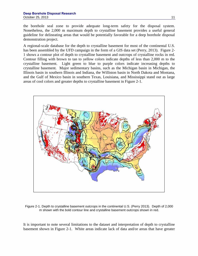
Deep Borehole Disposal Research October 25, 2013 11
the borehole seal zone to provide adequate long-term safety for the disposal system.
Nonetheless, the 2,000 m maximum depth to crystalline basement provides a useful general
guideline for delineating areas that would be potentially favorable for a deep borehole disposal
demonstration project.
A regional-scale database for the depth to crystalline basement for most of the continental U.S.
has been assembled by the UFD campaign in the form of a GIS data set (Perry, 2013). Figure 2-
1 shows a contour plot of depth to crystalline basement and outcrops of crystalline rocks in red.
Contour filling with brown to tan to yellow colors indicate depths of less than 2,000 m to the
crystalline basement. Light green to blue to purple colors indicate increasing depths to
crystalline basement. Major sedimentary basins, such as the Michigan basin in Michigan, the
Illinois basin in southern Illinois and Indiana, the Williston basin in North Dakota and Montana,
and the Gulf of Mexico basin in southern Texas, Louisiana, and Mississippi stand out as large
areas of cool colors and greater depths to crystalline basement in Figure 2-1.
Figure 2-1. Depth to crystalline basement outcrops in the continental U.S. (Perry 2013). Depth of 2,000 m shown with the bold contour line and crystalline basement outcrops shown in red.
It is important to note several limitations to the dataset and interpretation of depth to crystalline
basement shown in Figure 2-1. White areas indicate lack of data and/or areas that have greater
Deep Borehole Disposal Research
12 October 25, 2013
geological complexity that make interpretation of the depth to crystalline basement difficult.
Areas immediately adjacent to outcrops of crystalline basement generally have a shallow depth
to crystalline rocks, except where major faults have displaced the basement to greater depths
near the outcrops. The white areas in northern Minnesota, Wisconsin, Michigan, and the New
England states correspond to varying thicknesses of glacial deposits and have relatively shallow
depths to crystalline basement. Much of the western U.S., with the exception of the central
valley of California, is plotted in white because of lack of data and relatively greater structural
complexity. Interpretation of the depth to crystalline basement in the western U.S. would require
more intensive, local-scale data analysis or acquisition. White areas in Figure 2-1 should not be
interpreted as areas that are necessarily unsuitable for deep borehole disposal or for a deep
borehole demonstration project.
Overall, the analysis of depth to crystalline basement rocks indicates large areas of the
continental U.S. with depths of less than 2,000 m. Figure 2-2 shows the same interpretation of
depth to crystalline basement with the areas of less than 2,000 m depth shown with brown
shading for emphasis. Very large areas of the central and northern Midwest meet this guideline.
Another large area consists of the Atlantic coastal plain to the east and south of the Appalachian
Mountains. In addition, there are many other smaller areas in Texas and the western states with
depths of less than 2,000 m to the crystalline basement. As described earlier, much of northern
Minnesota, Wisconsin, and Michigan, and the New England states have outcrops of crystalline
rock or have relatively thin covers of glacial deposits. Also, as noted before, there are many
smaller areas with depths of less than 2,000 m to the crystalline basement that are scattered
across the more structurally complex western U.S.
As described earlier, this guideline for depth to crystalline basement rocks would be satisfied by
depths of less than 2,000 m to the basement or for locations with surface outcrops of crystalline
rock. Areas with outcropping crystalline basement rocks would have the advantage of direct
access to the rocks for detailed surface geological mapping and sampling; although the
characteristics of the crystalline rocks may be significantly different at the disposal depths.
Major structural features in the basement rocks, such as faults and shear zones, could also be
more directly observed. One potential disadvantage from a safety perspective is that major
throughgoing vertical structural features could have uninterrupted continuity between the deep
borehole disposal zone and the shallow subsurface, potentially providing higher-permeability
pathways for radionuclide migration. Areas with depths to the crystalline basement of up to
2,000 m are generally covered by stratified sedimentary rocks on stable continental platforms or
on the margins of sedimentary basins. An advantage of sedimentary rock cover is the low
vertical effective permeability created by typical alternating layers of coarse-grained clastic
rocks, carbonate rocks, and fine-grained sedimentary rocks, such as shales. Sedimentary rocks in
the stable continental interior typically contain saline connate fluids at depths of greater than a
few hundred meters, inhibiting vertical flow by density stratification and precluding utilization of
deep fluids as a groundwater supply resource. Sedimentary rocks may also function as a “cap”
on throughgoing vertical structural features in the underlying crystalline basement, disrupting
potential pathways for radionclide migration to the shallow subsurface. A disadvantage of
locations with sedimentary cover is that crystalline basement rocks cannot directly be mapped
and there would be uncertainty about the lithology and structure of crystalline basement rocks
that would be encountered in drilling.

Deep Borehole Disposal Research October 25, 2013 13
Figure 2-2. Depth to crystalline basement outcrops in the continental U.S. (Perry 2013). Depth of 2,000 m or less shown with brown shading and crystalline basement outcrops shown in red.
2.3.2 Crystalline Basement Lithology
The preferred host rock for deep borehole disposal is crystalline basement rock, which is a
generic term that includes a diversity of rocks of igneous and metamorphic origin. Crystalline
basement generally refers to the older, often Precambrian-age, rocks that underlie the
sedimentary cover in stable continental interior regions and sedimentary basins. The term
crystalline basement may also apply to geologically younger igneous and metamorphic rocks in
more recent tectonically active terranes, such as the Mesozoic-age plutonic rocks exposed in the
Sierra Nevada and similar rocks underlying the Central Valley in California.
The lithology of the crystalline basement may be important to deep borehole disposal in terms of
drilling and borehole completion, and with regard to post-closure safety of the disposal system.
Plutonic rocks in general, and granitic batholiths, in particular, tend to be more lithologically,
mineralogically, and mechanically homogeneous than volcanic or metamorphic rocks; although
variations in fracturing and the presence of fracture zones can make them hydrogeologically
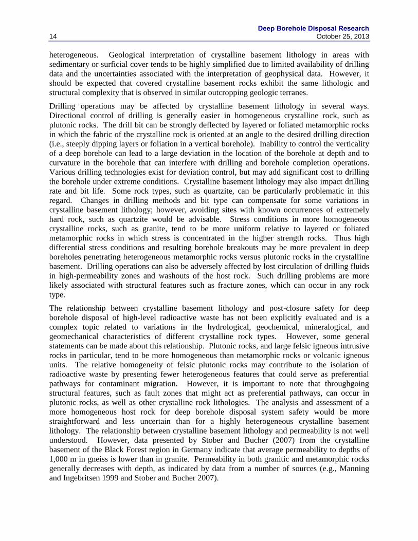
Deep Borehole Disposal Research
14 October 25, 2013
heterogeneous. Geological interpretation of crystalline basement lithology in areas with
sedimentary or surficial cover tends to be highly simplified due to limited availability of drilling
data and the uncertainties associated with the interpretation of geophysical data. However, it
should be expected that covered crystalline basement rocks exhibit the same lithologic and
structural complexity that is observed in similar outcropping geologic terranes.
Drilling operations may be affected by crystalline basement lithology in several ways.
Directional control of drilling is generally easier in homogeneous crystalline rock, such as
plutonic rocks. The drill bit can be strongly deflected by layered or foliated metamorphic rocks
in which the fabric of the crystalline rock is oriented at an angle to the desired drilling direction
(i.e., steeply dipping layers or foliation in a vertical borehole). Inability to control the verticality
of a deep borehole can lead to a large deviation in the location of the borehole at depth and to
curvature in the borehole that can interfere with drilling and borehole completion operations.
Various drilling technologies exist for deviation control, but may add significant cost to drilling
the borehole under extreme conditions. Crystalline basement lithology may also impact drilling
rate and bit life. Some rock types, such as quartzite, can be particularly problematic in this
regard. Changes in drilling methods and bit type can compensate for some variations in
crystalline basement lithology; however, avoiding sites with known occurrences of extremely
hard rock, such as quartzite would be advisable. Stress conditions in more homogeneous
crystalline rocks, such as granite, tend to be more uniform relative to layered or foliated
metamorphic rocks in which stress is concentrated in the higher strength rocks. Thus high
differential stress conditions and resulting borehole breakouts may be more prevalent in deep
boreholes penetrating heterogeneous metamorphic rocks versus plutonic rocks in the crystalline
basement. Drilling operations can also be adversely affected by lost circulation of drilling fluids
in high-permeability zones and washouts of the host rock. Such drilling problems are more
likely associated with structural features such as fracture zones, which can occur in any rock
type.
The relationship between crystalline basement lithology and post-closure safety for deep
borehole disposal of high-level radioactive waste has not been explicitly evaluated and is a
complex topic related to variations in the hydrological, geochemical, mineralogical, and
geomechanical characteristics of different crystalline rock types. However, some general
statements can be made about this relationship. Plutonic rocks, and large felsic igneous intrusive
rocks in particular, tend to be more homogeneous than metamorphic rocks or volcanic igneous
units. The relative homogeneity of felsic plutonic rocks may contribute to the isolation of
radioactive waste by presenting fewer heterogeneous features that could serve as preferential
pathways for contaminant migration. However, it is important to note that throughgoing
structural features, such as fault zones that might act as preferential pathways, can occur in
plutonic rocks, as well as other crystalline rock lithologies. The analysis and assessment of a
more homogeneous host rock for deep borehole disposal system safety would be more
straightforward and less uncertain than for a highly heterogeneous crystalline basement
lithology. The relationship between crystalline basement lithology and permeability is not well
understood. However, data presented by Stober and Bucher (2007) from the crystalline
basement of the Black Forest region in Germany indicate that average permeability to depths of
1,000 m in gneiss is lower than in granite. Permeability in both granitic and metamorphic rocks
generally decreases with depth, as indicated by data from a number of sources (e.g., Manning
and Ingebritsen 1999 and Stober and Bucher 2007).
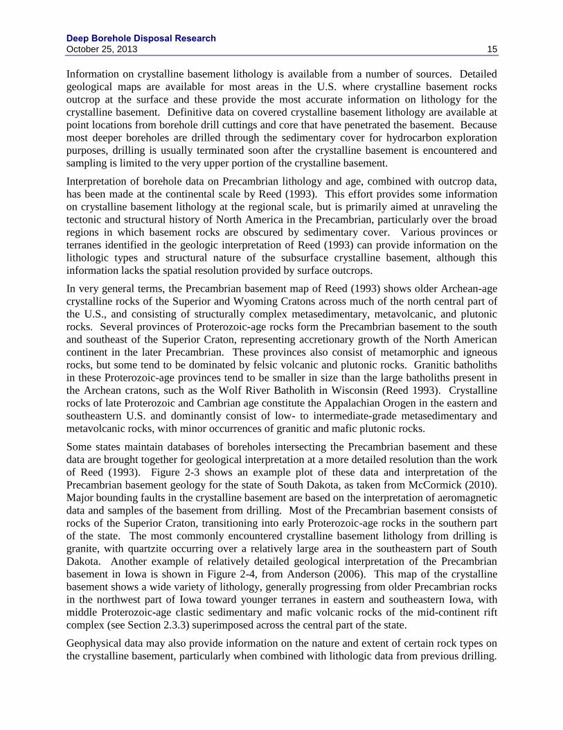
Deep Borehole Disposal Research October 25, 2013 15
Information on crystalline basement lithology is available from a number of sources. Detailed
geological maps are available for most areas in the U.S. where crystalline basement rocks
outcrop at the surface and these provide the most accurate information on lithology for the
crystalline basement. Definitive data on covered crystalline basement lithology are available at
point locations from borehole drill cuttings and core that have penetrated the basement. Because
most deeper boreholes are drilled through the sedimentary cover for hydrocarbon exploration
purposes, drilling is usually terminated soon after the crystalline basement is encountered and
sampling is limited to the very upper portion of the crystalline basement.
Interpretation of borehole data on Precambrian lithology and age, combined with outcrop data,
has been made at the continental scale by Reed (1993). This effort provides some information
on crystalline basement lithology at the regional scale, but is primarily aimed at unraveling the
tectonic and structural history of North America in the Precambrian, particularly over the broad
regions in which basement rocks are obscured by sedimentary cover. Various provinces or
terranes identified in the geologic interpretation of Reed (1993) can provide information on the
lithologic types and structural nature of the subsurface crystalline basement, although this
information lacks the spatial resolution provided by surface outcrops.
In very general terms, the Precambrian basement map of Reed (1993) shows older Archean-age
crystalline rocks of the Superior and Wyoming Cratons across much of the north central part of
the U.S., and consisting of structurally complex metasedimentary, metavolcanic, and plutonic
rocks. Several provinces of Proterozoic-age rocks form the Precambrian basement to the south
and southeast of the Superior Craton, representing accretionary growth of the North American
continent in the later Precambrian. These provinces also consist of metamorphic and igneous
rocks, but some tend to be dominated by felsic volcanic and plutonic rocks. Granitic batholiths
in these Proterozoic-age provinces tend to be smaller in size than the large batholiths present in
the Archean cratons, such as the Wolf River Batholith in Wisconsin (Reed 1993). Crystalline
rocks of late Proterozoic and Cambrian age constitute the Appalachian Orogen in the eastern and
southeastern U.S. and dominantly consist of low- to intermediate-grade metasedimentary and
metavolcanic rocks, with minor occurrences of granitic and mafic plutonic rocks.
Some states maintain databases of boreholes intersecting the Precambrian basement and these
data are brought together for geological interpretation at a more detailed resolution than the work
of Reed (1993). Figure 2-3 shows an example plot of these data and interpretation of the
Precambrian basement geology for the state of South Dakota, as taken from McCormick (2010).
Major bounding faults in the crystalline basement are based on the interpretation of aeromagnetic
data and samples of the basement from drilling. Most of the Precambrian basement consists of
rocks of the Superior Craton, transitioning into early Proterozoic-age rocks in the southern part
of the state. The most commonly encountered crystalline basement lithology from drilling is
granite, with quartzite occurring over a relatively large area in the southeastern part of South
Dakota. Another example of relatively detailed geological interpretation of the Precambrian
basement in Iowa is shown in Figure 2-4, from Anderson (2006). This map of the crystalline
basement shows a wide variety of lithology, generally progressing from older Precambrian rocks
in the northwest part of Iowa toward younger terranes in eastern and southeastern Iowa, with
middle Proterozoic-age clastic sedimentary and mafic volcanic rocks of the mid-continent rift
complex (see Section 2.3.3) superimposed across the central part of the state.
Geophysical data may also provide information on the nature and extent of certain rock types on
the crystalline basement, particularly when combined with lithologic data from previous drilling.
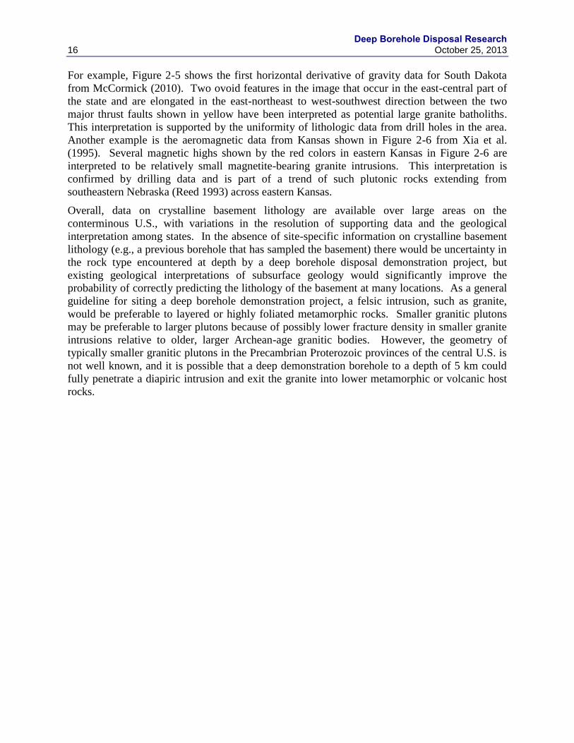
Deep Borehole Disposal Research
16 October 25, 2013
For example, Figure 2-5 shows the first horizontal derivative of gravity data for South Dakota
from McCormick (2010). Two ovoid features in the image that occur in the east-central part of
the state and are elongated in the east-northeast to west-southwest direction between the two
major thrust faults shown in yellow have been interpreted as potential large granite batholiths.
This interpretation is supported by the uniformity of lithologic data from drill holes in the area.
Another example is the aeromagnetic data from Kansas shown in Figure 2-6 from Xia et al.
(1995). Several magnetic highs shown by the red colors in eastern Kansas in Figure 2-6 are
interpreted to be relatively small magnetite-bearing granite intrusions. This interpretation is
confirmed by drilling data and is part of a trend of such plutonic rocks extending from
southeastern Nebraska (Reed 1993) across eastern Kansas.
Overall, data on crystalline basement lithology are available over large areas on the
conterminous U.S., with variations in the resolution of supporting data and the geological
interpretation among states. In the absence of site-specific information on crystalline basement
lithology (e.g., a previous borehole that has sampled the basement) there would be uncertainty in
the rock type encountered at depth by a deep borehole disposal demonstration project, but
existing geological interpretations of subsurface geology would significantly improve the
probability of correctly predicting the lithology of the basement at many locations. As a general
guideline for siting a deep borehole demonstration project, a felsic intrusion, such as granite,
would be preferable to layered or highly foliated metamorphic rocks. Smaller granitic plutons
may be preferable to larger plutons because of possibly lower fracture density in smaller granite
intrusions relative to older, larger Archean-age granitic bodies. However, the geometry of
typically smaller granitic plutons in the Precambrian Proterozoic provinces of the central U.S. is
not well known, and it is possible that a deep demonstration borehole to a depth of 5 km could
fully penetrate a diapiric intrusion and exit the granite into lower metamorphic or volcanic host
rocks.

Deep Borehole Disposal Research October 25, 2013 17
Figure 2-3. Terrane map of the Precambrian basement of South Dakota (from McCormick 2010)
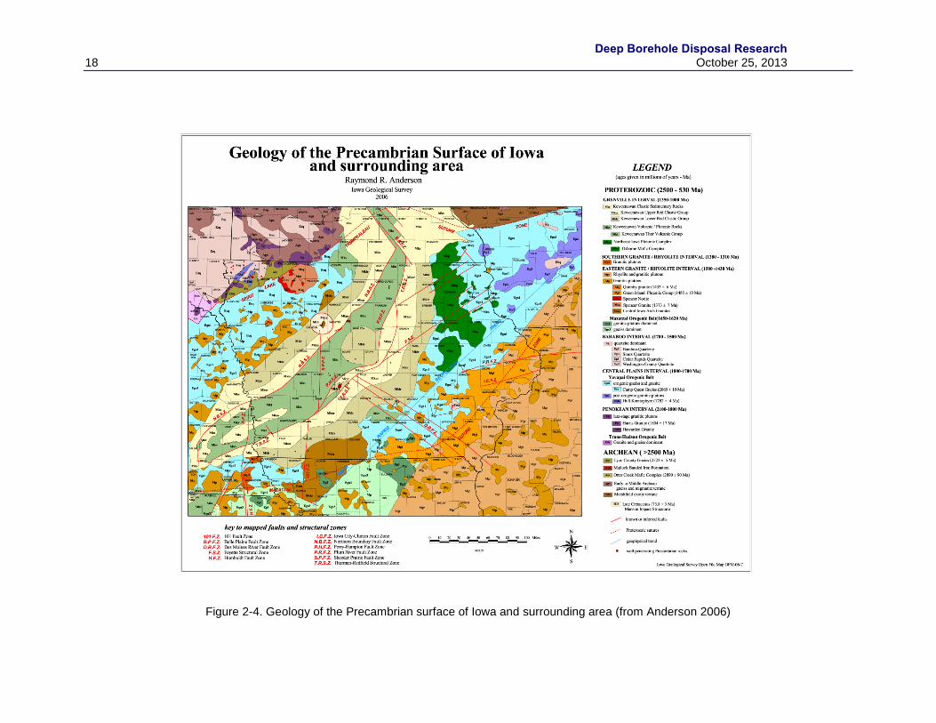
Deep Borehole Disposal Research
18 October 25, 2013
Figure 2-4. Geology of the Precambrian surface of Iowa and surrounding area (from Anderson 2006)
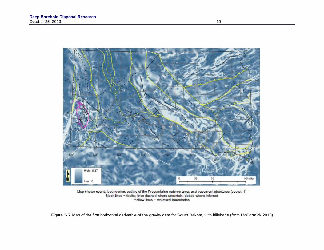
Deep Borehole Disposal Research October 25, 2013 19
Figure 2-5. Map of the first horizontal derivative of the gravity data for South Dakota, with hillshade (from McCormick 2010)
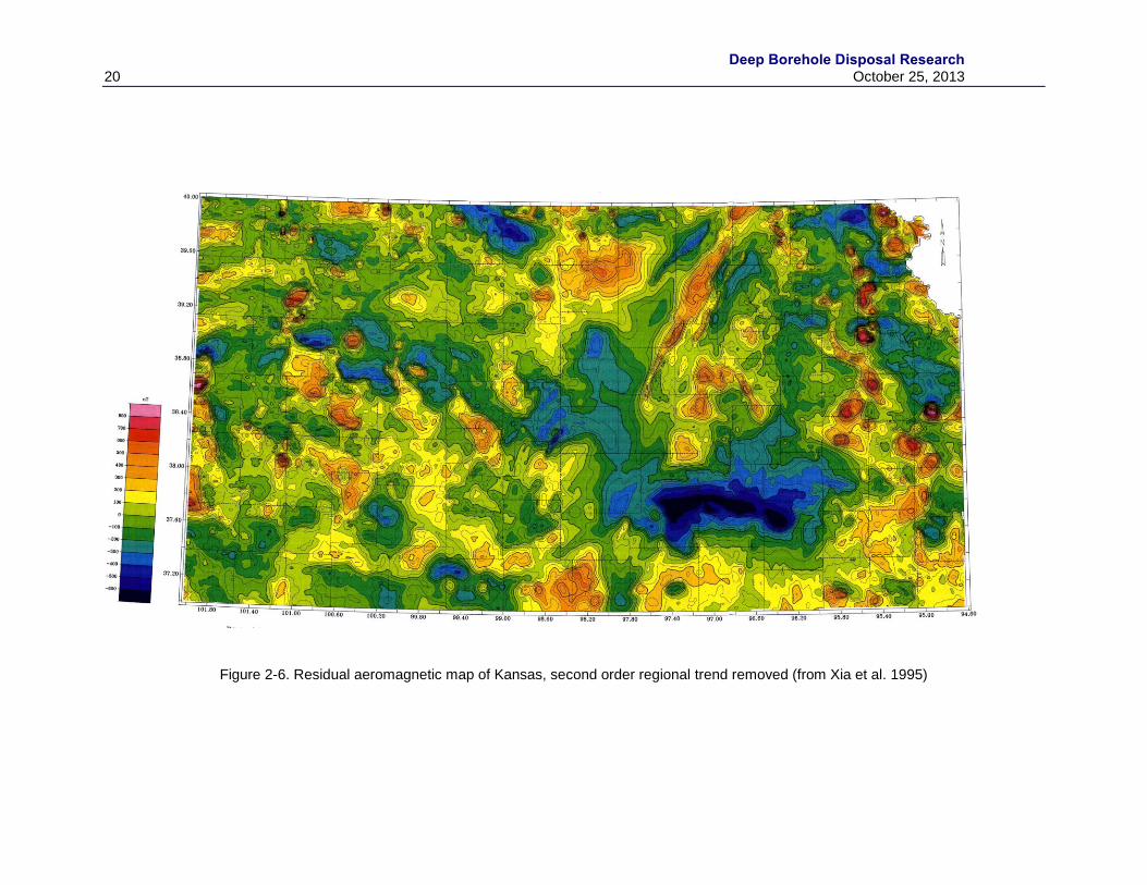
Deep Borehole Disposal Research
20 October 25, 2013
Figure 2-6. Residual aeromagnetic map of Kansas, second order regional trend removed (from Xia et al. 1995)
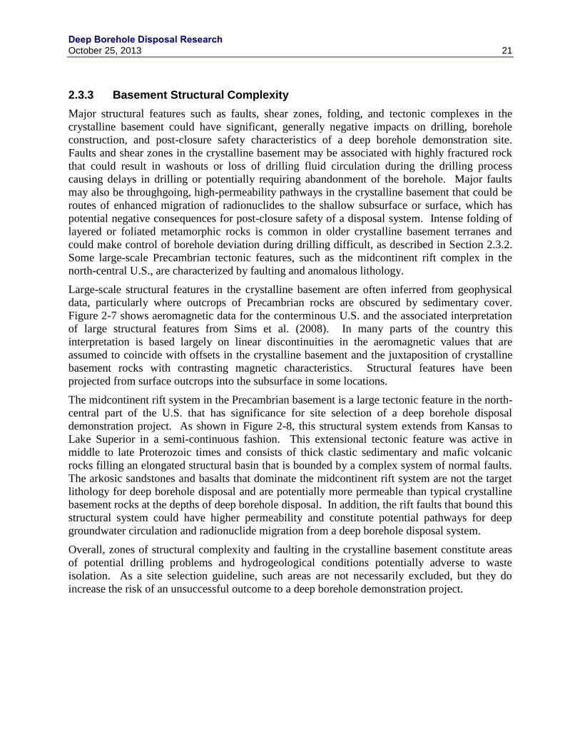
Deep Borehole Disposal Research October 25, 2013 21
2.3.3 Basement Structural Complexity
Major structural features such as faults, shear zones, folding, and tectonic complexes in the
crystalline basement could have significant, generally negative impacts on drilling, borehole
construction, and post-closure safety characteristics of a deep borehole demonstration site.
Faults and shear zones in the crystalline basement may be associated with highly fractured rock
that could result in washouts or loss of drilling fluid circulation during the drilling process
causing delays in drilling or potentially requiring abandonment of the borehole. Major faults
may also be throughgoing, high-permeability pathways in the crystalline basement that could be
routes of enhanced migration of radionuclides to the shallow subsurface or surface, which has
potential negative consequences for post-closure safety of a disposal system. Intense folding of
layered or foliated metamorphic rocks is common in older crystalline basement terranes and
could make control of borehole deviation during drilling difficult, as described in Section 2.3.2.
Some large-scale Precambrian tectonic features, such as the midcontinent rift complex in the
north-central U.S., are characterized by faulting and anomalous lithology.
Large-scale structural features in the crystalline basement are often inferred from geophysical
data, particularly where outcrops of Precambrian rocks are obscured by sedimentary cover.
Figure 2-7 shows aeromagnetic data for the conterminous U.S. and the associated interpretation
of large structural features from Sims et al. (2008). In many parts of the country this
interpretation is based largely on linear discontinuities in the aeromagnetic values that are
assumed to coincide with offsets in the crystalline basement and the juxtaposition of crystalline
basement rocks with contrasting magnetic characteristics. Structural features have been
projected from surface outcrops into the subsurface in some locations.
The midcontinent rift system in the Precambrian basement is a large tectonic feature in the north-
central part of the U.S. that has significance for site selection of a deep borehole disposal
demonstration project. As shown in Figure 2-8, this structural system extends from Kansas to
Lake Superior in a semi-continuous fashion. This extensional tectonic feature was active in
middle to late Proterozoic times and consists of thick clastic sedimentary and mafic volcanic
rocks filling an elongated structural basin that is bounded by a complex system of normal faults.
The arkosic sandstones and basalts that dominate the midcontinent rift system are not the target
lithology for deep borehole disposal and are potentially more permeable than typical crystalline
basement rocks at the depths of deep borehole disposal. In addition, the rift faults that bound this
structural system could have higher permeability and constitute potential pathways for deep
groundwater circulation and radionuclide migration from a deep borehole disposal system.
Overall, zones of structural complexity and faulting in the crystalline basement constitute areas
of potential drilling problems and hydrogeological conditions potentially adverse to waste
isolation. As a site selection guideline, such areas are not necessarily excluded, but they do
increase the risk of an unsuccessful outcome to a deep borehole demonstration project.
Deep Borehole Disposal Research
22 October 25, 2013
Figure 2-7. Precambrian basement structure map and aeromagnetic data. (Perry, 2013, source: Sims et al. 2008)
2.3.4 Horizontal Stress
It is important to understand regional and localized horizontal stress in order to best ensure
borehole integrity and characterize the disturbed rock zone (DRZ) around the borehole. Where
the magnitude of the two principle directions of horizontal stress differ (Sh = orientation of least
horizontal in situ stress and SH = orientation of greatest in situ horizontal stress), the borehole
walls may spall and form breakouts along the direction of Sh. Thus, when borehole breakout
occurs, the borehole becomes more of an oval with the dimension of the borehole being greater
in the direction of the minimum horizontal stress (Figure 2-9).
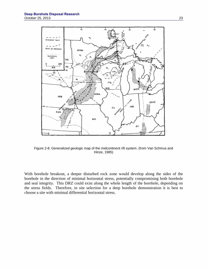
Deep Borehole Disposal Research October 25, 2013 23
Figure 2-8. Generalized geologic map of the midcontinent rift system. (from Van Schmus and Hinze, 1985)
With borehole breakout, a deeper disturbed rock zone would develop along the sides of the
borehole in the direction of minimal horizontal stress, potentially compromising both borehole
and seal integrity. This DRZ could exist along the whole length of the borehole, depending on
the stress fields. Therefore, in site selection for a deep borehole demonstration it is best to
choose a site with minimal differential horizontal stress.

Deep Borehole Disposal Research
24 October 25, 2013
Figure 2-9. Cross section of a borehole wall showing two diametrically opposed breakouts with major and minor horizontal in situ stress axis displayed. (source: Lee and Haimson, 1993).
Horizontal stress data have been compiled as part of The World Stress Map Project (http://dc-
app3-14.gfz-potsdam.de/pub/introduction/introduction_frame.html). Data for the United States
are presented in Figure 2-10. Breakouts (lines with inner-facing arrows) have been measured
along the West Coast, in Texas, Oklahoma and Colorado. In the mid-west the majority of
borehole breakouts are measured in southern Illinois and Indiana. Borehole breakouts have also
been measured in Ohio, Kentucky, Virginia, West Virginia, Ohio, Pennsylvania and New York.
North Dakota, South Dakota, Iowa, Michigan, Alabama and North Carolina are void of stress
measurements and very few have been made in Kansas, Minnesota, and northern Missouri.
The color of the symbols shown in Figure 2-10 gives an indication of the stress-regimes in the
different areas in the country. California appears to be dominated by strike-slip (green) and
thrust (blue) faulting. East of the coastal states (Idaho, Nevada, Utah, Arizona, and New
Mexico) is dominated by a normal faulting regime. New England and New York appears to be
dominated by thrust faulting. Zoback and Zoback (1989) generalize the stress fields on the
United States (Figure 2-10)
SH SH
Sh
Sh
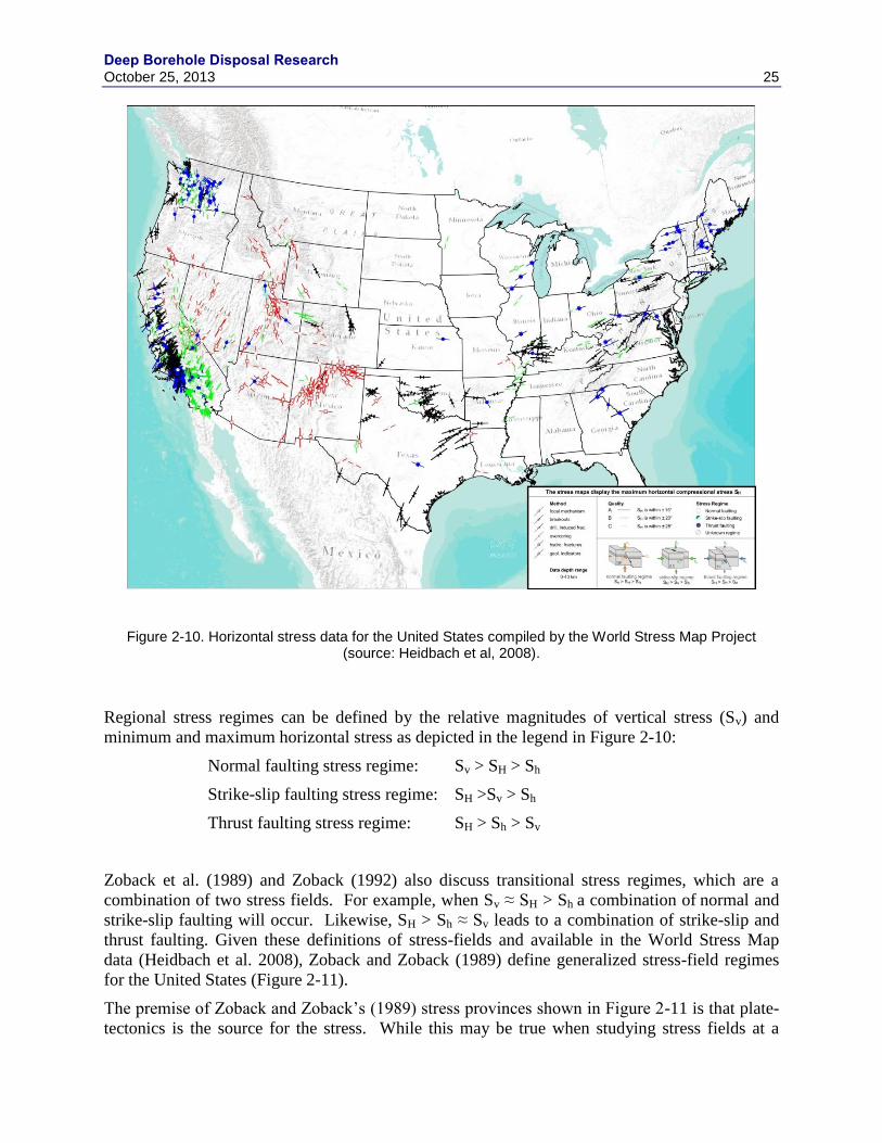
Deep Borehole Disposal Research October 25, 2013 25
Figure 2-10. Horizontal stress data for the United States compiled by the World Stress Map Project (source: Heidbach et al, 2008).
Regional stress regimes can be defined by the relative magnitudes of vertical stress (Sv) and
minimum and maximum horizontal stress as depicted in the legend in Figure 2-10:
Normal faulting stress regime: Sv > SH > Sh
Strike-slip faulting stress regime: SH >Sv > Sh
Thrust faulting stress regime: SH > Sh > Sv
Zoback et al. (1989) and Zoback (1992) also discuss transitional stress regimes, which are a
combination of two stress fields. For example, when Sv ≈ SH > Sh a combination of normal and
strike-slip faulting will occur. Likewise, SH > Sh ≈ Sv leads to a combination of strike-slip and
thrust faulting. Given these definitions of stress-fields and available in the World Stress Map
data (Heidbach et al. 2008), Zoback and Zoback (1989) define generalized stress-field regimes
for the United States (Figure 2-11).
The premise of Zoback and Zoback’s (1989) stress provinces shown in Figure 2-11 is that plate-
tectonics is the source for the stress. While this may be true when studying stress fields at a

Deep Borehole Disposal Research
26 October 25, 2013
regional scale, there are other factors impacting stress fields at a local scale. Erosion,
denudation, over consolidation of sediments, and the sequence of glacial loading, unloading,
isostatic movements and postglacial uplift can also impact horizontal stress (Amedei and
Stephansson 1997).
Figure 2-11. Generalized stress provinces for the United States (source: Zoback and Zoback 1989).
Overall, data and interpretations of the stress state in the upper crust provide a general picture of
the stress regimes and the stress orientations on a regional scale, but provide little information on
the magnitude of the anisotropy in horizontal stress. Observations of borehole breakouts, or lack
thereof, in individual existing boreholes at the sub-regional scale would likely provide a
reasonable indication of the risk of deep borehole instability. Broad areas of uniform orientation
in horizontal stress, such as the northeast-southwest compressive stress state over much of the
mid-continental U.S., probably offer a more predictable and homogeneous regime in differential
horizontal stress than the tectonically more complex western and southwestern U.S. In this
sense, the mid-plate region of the U.S. (see Figure 2-11) may be more favorable for siting a deep
borehole demonstration project.
2.3.5 Tectonic Uplift
Tectonic uplift is an increase in elevation of the earth surface due to tectonic or isostatic
processes. Two converging plates can cause continental crustal thickening leading to tectonic
uplift. The elevation of the earth can also increase due to an isostatic response to unloading, thus
the two processes need to be distinguished. Tectonic uplift is important to deep borehole
disposal, not because it has a direct impact on performance, but because in areas of tectonic
Deep Borehole Disposal Research October 25, 2013 27
activity there is an increased risk of seismicity, volcanism, and active faulting (see Section
2.3.8). The risk of exhumation of waste from deep borehole disposal within a regulatory time
frame is much lower than for a mined repository because of the greater disposal depth.
Isostatic uplift, or post-glacial rebound, is the increase in elevation, or rise of the land surface
that was lowered during past glaciations. The isostatic uplift rates in the continental United
States are greater in the northern states (closer to the margins of the ice sheet - see Figure 2-12)
decreasing to the south.
Rates of isostatic uplift have been estimated (e.g., Paulsen at al. 2005); however, less data are
readily available for tectonic uplift rates. Areas where the arrows are pointing towards each
other in Figure 2-11 are areas where tectonic uplift is more likely. However, this figure does not
give any indication of the rates of uplift and whether or not they are significant.
Quaternary faulting and volcanism, high tectonic uplift rates and horizontal stress are all
indicators of tectonic activity. As stated above, tectonic activity is an important process that
could negatively impact deep borehole performance due to an increased risk of seismicity,
volcanism, and active faulting. After a demonstration study area for deep borehole disposal has
been chosen, a more detailed study of the potential of tectonic impacts on the demonstration
should be under taken.
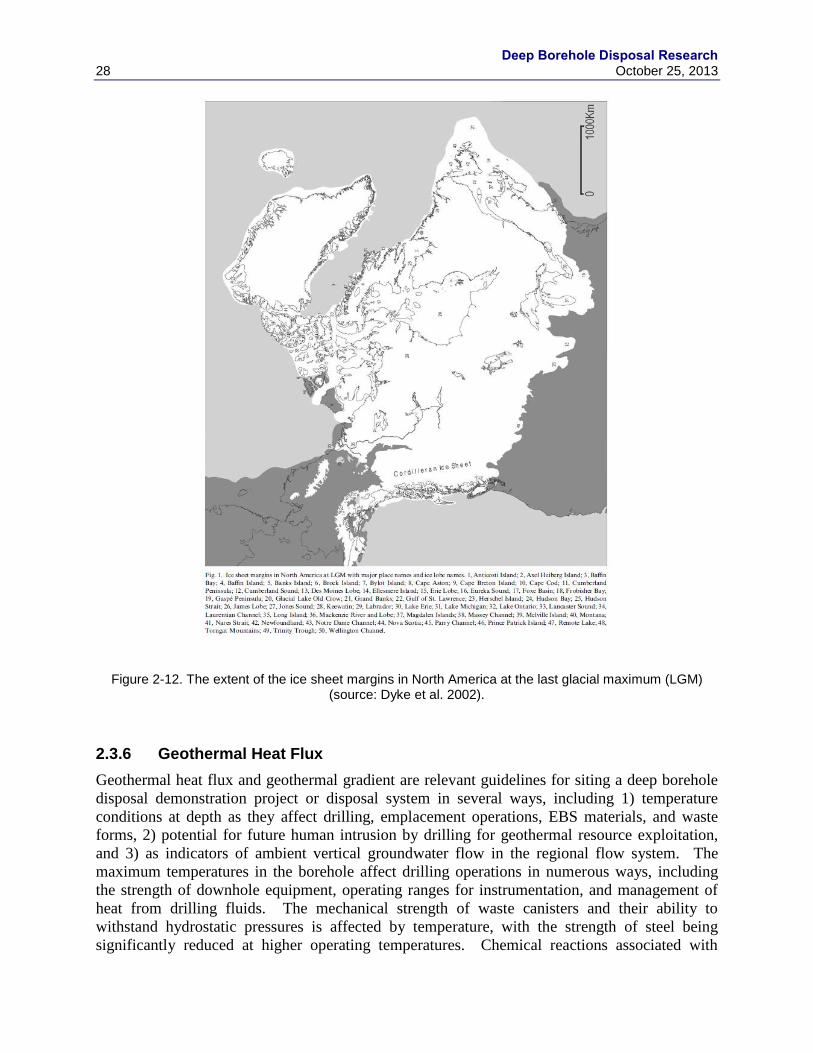
Deep Borehole Disposal Research
28 October 25, 2013
Figure 2-12. The extent of the ice sheet margins in North America at the last glacial maximum (LGM) (source: Dyke et al. 2002).
2.3.6 Geothermal Heat Flux
Geothermal heat flux and geothermal gradient are relevant guidelines for siting a deep borehole
disposal demonstration project or disposal system in several ways, including 1) temperature
conditions at depth as they affect drilling, emplacement operations, EBS materials, and waste
forms, 2) potential for future human intrusion by drilling for geothermal resource exploitation,
and 3) as indicators of ambient vertical groundwater flow in the regional flow system. The
maximum temperatures in the borehole affect drilling operations in numerous ways, including
the strength of downhole equipment, operating ranges for instrumentation, and management of
heat from drilling fluids. The mechanical strength of waste canisters and their ability to
withstand hydrostatic pressures is affected by temperature, with the strength of steel being
significantly reduced at higher operating temperatures. Chemical reactions associated with
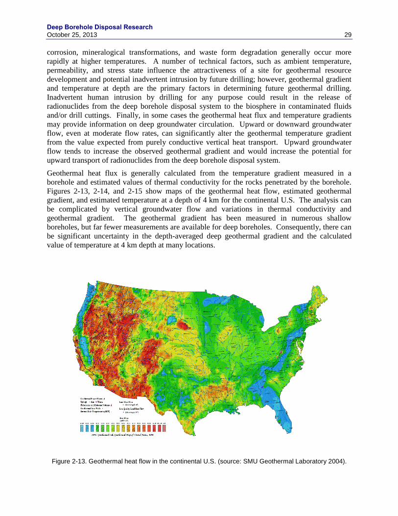
Deep Borehole Disposal Research October 25, 2013 29
corrosion, mineralogical transformations, and waste form degradation generally occur more
rapidly at higher temperatures. A number of technical factors, such as ambient temperature,
permeability, and stress state influence the attractiveness of a site for geothermal resource
development and potential inadvertent intrusion by future drilling; however, geothermal gradient
and temperature at depth are the primary factors in determining future geothermal drilling.
Inadvertent human intrusion by drilling for any purpose could result in the release of
radionuclides from the deep borehole disposal system to the biosphere in contaminated fluids
and/or drill cuttings. Finally, in some cases the geothermal heat flux and temperature gradients
may provide information on deep groundwater circulation. Upward or downward groundwater
flow, even at moderate flow rates, can significantly alter the geothermal temperature gradient
from the value expected from purely conductive vertical heat transport. Upward groundwater
flow tends to increase the observed geothermal gradient and would increase the potential for
upward transport of radionuclides from the deep borehole disposal system.
Geothermal heat flux is generally calculated from the temperature gradient measured in a
borehole and estimated values of thermal conductivity for the rocks penetrated by the borehole.
Figures 2-13, 2-14, and 2-15 show maps of the geothermal heat flow, estimated geothermal
gradient, and estimated temperature at a depth of 4 km for the continental U.S. The analysis can
be complicated by vertical groundwater flow and variations in thermal conductivity and
geothermal gradient. The geothermal gradient has been measured in numerous shallow
boreholes, but far fewer measurements are available for deep boreholes. Consequently, there can
be significant uncertainty in the depth-averaged deep geothermal gradient and the calculated
value of temperature at 4 km depth at many locations.
Figure 2-13. Geothermal heat flow in the continental U.S. (source: SMU Geothermal Laboratory 2004).

Deep Borehole Disposal Research
30 October 25, 2013
Figure 2-14. Estimated geothermal gradient in the continental U.S. (source: SMU Geothermal Laboratory 2004).
Figure 2-15. Estimated temperature at 4 km depth in the continental U.S. (source: SMU Geothermal Laboratory 2004)

Deep Borehole Disposal Research October 25, 2013 31
The map of geothermal heat flow in Figure 2-13 shows large variability in heat flux, with
generally higher values in the western U.S. and lower values in eastern U.S. Exceptions include
relatively low heat flow in the coast ranges of Washington, Oregon, and northern California, and
the Central Valley of California. Notably higher heat flow also occurs in south central South
Dakota, in a broad area from eastern Texas to western Mississippi, and in isolated areas scattered
in the eastern U.S. The area of high heat flow in south central South Dakota is paired with an
area of anomalously low heat flow in west central South Dakota, centered on the topographically
elevated Black Hills. This feature has been interpreted as the result of a regional-scale
groundwater flow system in which downward flow suppresses the heat flux in the Black Hills
and emerges as deep upward groundwater flow near the lowlands of the Missouri River in south
central South Dakota, enhancing the geothermal heat flow in that area.
The maps of geothermal gradient and estimated temperature at 4 km depth in Figures 2-14 and 2-
15 show similar patterns to the heat flux map, but have information that is more directly related
to the temperature conditions expected at depths of interest for the deep borehole demonstration
project. The geothermal gradient is generally low to moderate in the central and eastern parts of
the U.S., with generally higher values of the geothermal gradient in the west. Very high values
of the geothermal gradient extend from the Yellowstone volcanic area in northwestern
Wyoming, across the Snake River plain and into southeastern Oregon and northwestern Nevada.
Note that temperatures at a depth of 4 km have not been projected for most of the western U.S. in
Figure 2-15 because of the high variability in temperature gradients and lack of data.
Overall, the analysis of geothermal heat flux and temperature gradient with depth indicates that
there are large areas of low to moderate geothermal gradient in the Midwestern and eastern parts
of the U.S., with some smaller areas of low to moderate geothermal gradient in the western U.S.
There is no definitive basis for setting a threshold value for average geothermal gradient or heat
flux to use as a guideline for siting a deep borehole demonstration project. A temperature range
of 160 ºC to 180 ºC would correspond to a geothermal gradient of about 30 ºC/km for a 5,000 m
deep borehole. In terms of attractiveness for geothermal resource development, current deep
drilling for enhanced geothermal systems (EGS), such as that at Soultz, France and the Cooper
Basin, Australia, is in locations with geothermal gradients of greater than 30 ºC/km (MIT 2006).
Given the abundance of potential locations with geothermal gradients of greater than 30 ºC/km in
the U.S., it is unlikely that locations with lower values of geothermal gradient would be at risk
for deep drilling for EGS development in the future.
2.3.7 Topographic Relief and Hydraulic Gradient
Groundwater flow is dominantly driven by topographic relief in most flow systems. Such flow
occurs in local, intermediate, and regional flow patterns, as identified in the classical analysis of
topographically driven flow by Tóth, (1963). The rate of topographically driven groundwater
flow, both horizontally and vertically, is determined by recharge rates, the pattern of topographic
relief, the permeability structure of the subsurface, and depth. Recharge rates vary both
geographically and topographically. Topographic relief varies both locally and regionally, with
extensive areas of higher topographic relief occurring in mountainous regions, such as much of
the western U.S. and the Appalachian Mountains in the eastern U.S. One measure of
topographic relief is the average local slope, as plotted for the continental U.S. in Figure 2-16.
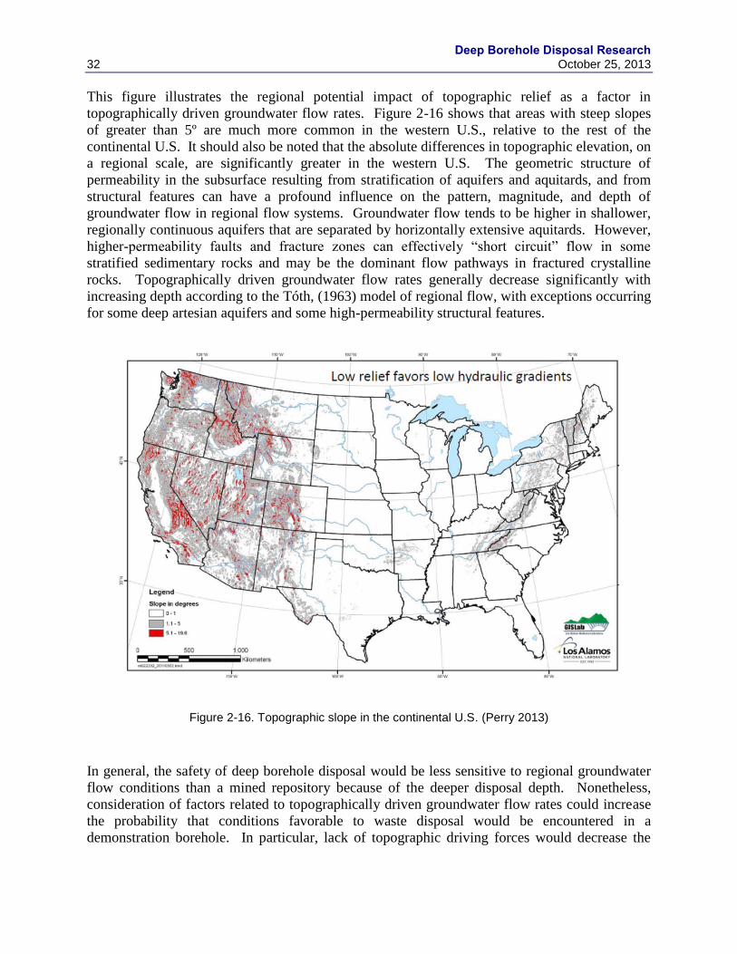
Deep Borehole Disposal Research
32 October 25, 2013
This figure illustrates the regional potential impact of topographic relief as a factor in
topographically driven groundwater flow rates. Figure 2-16 shows that areas with steep slopes
of greater than 5º are much more common in the western U.S., relative to the rest of the
continental U.S. It should also be noted that the absolute differences in topographic elevation, on
a regional scale, are significantly greater in the western U.S. The geometric structure of
permeability in the subsurface resulting from stratification of aquifers and aquitards, and from
structural features can have a profound influence on the pattern, magnitude, and depth of
groundwater flow in regional flow systems. Groundwater flow tends to be higher in shallower,
regionally continuous aquifers that are separated by horizontally extensive aquitards. However,
higher-permeability faults and fracture zones can effectively “short circuit” flow in some
stratified sedimentary rocks and may be the dominant flow pathways in fractured crystalline
rocks. Topographically driven groundwater flow rates generally decrease significantly with
increasing depth according to the Tóth, (1963) model of regional flow, with exceptions occurring
for some deep artesian aquifers and some high-permeability structural features.
Figure 2-16. Topographic slope in the continental U.S. (Perry 2013)
In general, the safety of deep borehole disposal would be less sensitive to regional groundwater
flow conditions than a mined repository because of the deeper disposal depth. Nonetheless,
consideration of factors related to topographically driven groundwater flow rates could increase
the probability that conditions favorable to waste disposal would be encountered in a
demonstration borehole. In particular, lack of topographic driving forces would decrease the
Deep Borehole Disposal Research October 25, 2013 33
likelihood of upward hydraulic gradients in fluid potential and increase the likelihood of very
old, highly saline fluids at depth.
Topographic slope, as shown in Figure 2-16, provides a gross measure of the potential for
significant deep groundwater circulation that could be important to the deep borehole disposal
concept. As described above, groundwater flow rates at depth are affected by several factors in
addition to topographic relief. In particular, the variability and structure of permeability can be
highly important in determining hydraulic gradients and flow rates at depth. Areas with high
topographic slope and relief may have very low groundwater flow rates at depths of several
thousand meters, if the low recharge rates and the distribution of permeability within the rocks
preclude such flow. Areas with low topographic relief are very likely to have extremely low
groundwater flow rates at deep borehole disposal depths, regardless of recharge rates and
permeability structure. Low groundwater flow rates at depth would be further reduced from the
density stratification of highly saline groundwater (Park et al. 2009) that typically develops over
geological time scales in such stagnant deep groundwater systems. It should be noted that
topographically driven deep groundwater circulation can be transmitted over horizontal distances
of greater than 100 km in some cases, as illustrated by the anomalous geothermal heat flow
pattern inferred to be related to the topographically high Black Hills in South Dakota described
in Section 2.3.6.
Overall, regional topographic relief is a rough guideline for site selection regarding the potential
for deep circulation of groundwater and the potential intrusion of younger, lower-salinity
groundwater into the crystalline basement at the depths of deep borehole disposal. In some
hydrogeologic settings low-permeability aquitards and the decrease in permeability with depth
would preclude deep groundwater circulation regardless of topographic driving forces; however,
proximity to high topographic relief increases the probability of deep circulation and upward
hydraulic gradients, which are characteristics that are unfavorable for waste isolation.
2.3.8 Quaternary Faults and Volcanism
Deep borehole disposal sites should not be located in the vicinity of active faults or volcanoes.
Volcanism could lead to a direct release and dispersal of radionuclides by way of eruption
through the disposal zone. Active faults should be avoided because of the increased risk of
seismicity and the greater potential of high permeability pathways through the rejuvenated faults.
As a guide, Quaternary faults and volcanism are of importance to deep borehole disposal because
of their greater likelihood of being active in comparison to older faults and volcanoes. However,
being close to a Quaternary fault or volcano does not disqualify a site for a deep borehole
demonstration project. It does means that the area should be studied in greater detail to
determine the likelihood of active faulting or volcanism at the site.
Figure 2-17 shows Plio-Quaternary volcanic fields and Quaternary faults in the continental
United States. Quaternary faults and Plio-Quaternary volcanic fields are primarily located in
western United States. A few Quaternary faults are located in Kansas, Oklahoma, and Texas up
the Rio Grande Valley to Colorado. Moving west, the number of faults increase. Large volcanic
fields can be seen in Idaho, Oregon, and northern California.
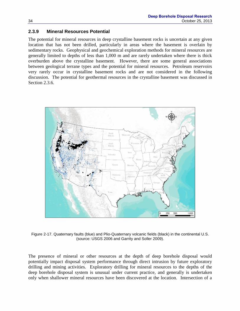
Deep Borehole Disposal Research
34 October 25, 2013
2.3.9 Mineral Resources Potential
The potential for mineral resources in deep crystalline basement rocks is uncertain at any given
location that has not been drilled, particularly in areas where the basement is overlain by
sedimentary rocks. Geophysical and geochemical exploration methods for mineral resources are
generally limited to depths of less than 1,000 m and are rarely undertaken where there is thick
overburden above the crystalline basement. However, there are some general associations
between geological terrane types and the potential for mineral resources. Petroleum reservoirs
very rarely occur in crystalline basement rocks and are not considered in the following
discussion. The potential for geothermal resources in the crystalline basement was discussed in
Section 2.3.6.
Figure 2-17. Quaternary faults (blue) and Plio-Quaternary volcanic fields (black) in the continental U.S. (source: USGS 2006 and Garrity and Soller 2009).
The presence of mineral or other resources at the depth of deep borehole disposal would
potentially impact disposal system performance through direct intrusion by future exploratory
drilling and mining activities. Exploratory drilling for mineral resources to the depths of the
deep borehole disposal system is unusual under current practice, and generally is undertaken
only when shallower mineral resources have been discovered at the location. Intersection of a

Deep Borehole Disposal Research October 25, 2013 35
future exploratory borehole with waste in a vertical deep disposal borehole would be unlikely
due to the relatively small target presented by a vertical disposal zone. However, a future
mineral exploratory borehole could encounter radionuclide contamination that had migrated
laterally from the waste disposal interval. Current mining is conducted at deep borehole disposal
depths at a few locations, notably gold mines in South Africa. The size of the ore body must be
large and the ore grade must be high to make mining operations at such depths economically
viable. In addition, mines to these depths are typically developed by following ore downward
from shallower deposits.
A number of ore deposits are associated with felsic intrusive rocks, such as those considered for
deep borehole disposal in crystalline basement, including porphyry base metal deposits, iron
deposits, cordilleran vein-type base and precious metal deposits, pegmatites, and granitic tin and
uranium deposits (Guilbert and Park 1986). Of these deposit types, porphyry base metal deposits
and cordilleran vein-type base and precious metal deposits would be the ones that could have
sufficiently high ore grade and economic value to warrant underground mining to depths of
several kilometers. These magmatic and post-magmatic hydrothermal ore deposits are
uncommon occurrences in the total area of the associated intrusive rocks, but are widely
distributed in crystalline basement rocks that can potentially host them. They are typically
formed within 1 km of the surface at the time of their genesis, so they would be unlikely to occur
in crystalline basement terranes that have experienced significant erosion and denudation.
Alteration halos for porphyry base metal deposits and cordilleran vein-type base and precious
metal deposits may indicate their potential existence at depth, but initial discoveries of such
deposits typically occurs in surface outcrops. Prediction of the location of these types of ore
deposits in the crystalline basement under significant sedimentary rock cover would be very
difficult, although randomly encountering such an ore deposit in a deep disposal borehole would
be very unlikely.
Some of the world’s richest gold deposits are related to clastic deposition of gold and sulfide
minerals in Precambrian conglomerates, such as those in the Witwatersrand gold deposits in
South Africa (Guilbert and Park 1986). These deposits formed under low oxygenated
atmospheric conditions about 2.7 to 2.4 billion years ago, which permitted fluvial transport of
minerals without oxidation and dissolution. Such geochemical conditions existed in the
Archean, but ended in the Proterozoic period, limiting the potential time period under which
these deposits could have formed. Most of the crystalline basement Precambrian rocks south of
the Superior Craton in the mid-western and southern U.S. are younger than about 2.0 billion
years (Reed 1993), implying that Witwatersrand type gold deposits would not be present in the
crystalline basement rocks over most of the U.S. In addition, the clastic metamorphic rocks that
would host this type of ore deposit are not the target host rock for the deep borehole disposal
demonstration project.
Deposits related to subaerial volcanism that might exist in the crystalline basement include
epithermal silver-gold deposits, bulk low-grade silver deposits, and basalt-andesite copper
deposits (Guilbert and Park 1986). Of these deposit types, epithermal silver-gold deposits could
have sufficient economic value to warrant mining at depths of several kilometers, although no
such ore deposits have been mined to the depths of deep borehole disposal. Low-grade or
disseminated precious metal deposits can be economically mined by open pit methods, but are
not amenable to mining by underground methods at the depths of deep borehole disposal.
Epithermal gold deposits could be present in the felsic intrusive and volcanic geological
Deep Borehole Disposal Research
36 October 25, 2013
environment of the crystalline basement, such as the large Southern and Eastern Granite-
Rhyolite Provinces identified in Reed (1993).
Mineral deposits that are related to submarine volcanism include massive sulfide deposits and
banded iron formations. Massive sulfide deposits potentially could be of sufficient size and
economic value to warrant mining to great depths. Such ore deposits are formed in oceanic crust
and are subsequently incorporated into the continental crystalline basement by tectonic accretion
of the host terrane. Such geological conditions more commonly occur in Archean age rocks of
the older continental craton that exist in the northern mid-western region of the U.S. Very large
massive sulfide deposits potentially can be detectable at great depths using geophysical methods.
Another class of large mineral deposits is related to layered mafic intrusions, including the
Bushveld igneous complex chromium-platinum deposit and the Sudbury complex copper, nickel-
platinum deposit (Guilbert and Park 1986). Such deposits are mined to depths of over 2 km, thus
having some potential for human intrusion into a deep borehole disposal system. The layered
mafic rocks that host this type of ore deposit are not the target host rock for the deep borehole
disposal demonstration project. Very large layered mafic deposits potentially can be detectable
at great depths using geophysical methods.
Athabasca-type unconformity-related uranium deposits can occur near the interface between
overlying sandstone and underlying crystalline basement rocks containing, in particular,
graphitic schists that are hypothesized to have been the source of geochemical reducing agents
for precipitation of uranium ore. Such uranium deposits can be quite large and economically
exploitable by underground mining; however, mining depths are not as great as deep borehole
disposal. Precambrian unconformity-related uranium deposits could occur in the basement rocks
of the U.S. in the mid-continent rift structure (see Section 2.3.3), which contains arkosic
sandstones overlying the crystalline basement.
Overall, there is a low probability of mineral deposits at a given site that could be economically
exploited in crystalline basement rocks of the U.S. at the depths of several kilometers that pose a
risk of inadvertent human intrusion to a deep borehole disposal system. The existence of most
mineral deposits in the crystalline basement at depths of several kilometers typically could not be
determined by existing geophysical or geochemical methods. General guidelines on the potential
for mineral deposits are based on the assumption that large gold and base metal deposits are less
likely to occur in felsic Proterozoic-age rocks than in heterogeneous Archean crystalline
basement.
2.4 Logistical and Other Selection Guidelines
2.4.1 Drilling Contractor Availability
Although deep drilling is now common within the petroleum industry, there are few examples
where large diameter wells have been drilled in crystalline bedrock to depths of 5,000 meters.
The well most closely resembling the objectives of the deep borehole disposal demonstration
project is the KTB Hauptbohrung scientific hole that was drilled in Germany in 1990 to 1994 to
a depth of 9,101 m. Casing of 13-5/8 inch diameter was installed to a depth of 6,000 m in a 14-
3/4 inch borehole. In reality, the KTB was a technology development hole and provided

Deep Borehole Disposal Research October 25, 2013 37
experience on automated drilling, bit technology, directional control and other issues related to
deep drilling in crystalline bedrock.
The drilling industry is highly specialized, with drilling contractors normally providing only the
drilling rig, fluid circulation system and drill pipe. Drilling supervision is the responsibility of
the client's representative, or “company man”. Other support services, equipment and materials
are available from other specialized contractors and will be discussed in the next section. Oil
field rigs and support services are available throughout the US, but costs will vary depending on
distance from supply points and regional offices.
The borehole reference design presented in Arnold et al. (2011a) requires a 2,000 horsepower
drilling rig with a minimum hook load of 1,000,000 pounds. Although rigs this large are not
common, there are at least seven drilling contractors in the U.S. that have this capability. These
rigs are located in the western and southwestern U.S. Their availability and cost are dependent
on demand, and utilization rates are presently approaching 80% industry wide. Demand is
expected to increase in the short term, based on current trends of expanding petroleum
exploration and production.
2.4.2 Drilling Support Services Availability
Drilling support services are available through companies that work with the petroleum drilling
sector. The supply chain within the US is robust and it is expected that services and supplies can
be procured by competitive bid addressed to a number of different suppliers for each type of
equipment or service. A few of the major support items are discussed below. Major support
contractors have offerings in a number of these areas and can also provide comprehensive
management services.
A significant advance in drilling technology is Measurement While Drilling (MWD) that
measures borehole parameters and transmits data to the surface in real time. The DBD
demonstration will have strict tolerances for dog legs and deviations from vertical. MWD
provides the ability to perform quality control as the borehole is being drilled. Should the
borehole start to exceed specifications, corrections can be made using steerable drilling
assemblies.
The borehole reference design has called for three casing strings that will be cemented in place,
plus a “guidance liner” that will provide the conduit for the emplacement of the waste canisters.
The casing strings are of standard oil field size and are available from a number of different
suppliers. Cementing the casing also requires a specialized contractor who can provide an
analysis of the borehole requirements, cement mixtures to satisfy those requirements and
specialized equipment to install the cement. Cement may also be used during the drilling of the
well to aid in sealing zones of lost circulation.
Drilling fluid, or “mud”, will be required and can become a significant cost in the drilling of the
well. Mud is used to lubricate and cool the bit, transport cuttings to the surface and condition the
hole to prevent loss of fluids to the formation. The quality of the mud is controlled by mud
engineers, and returns of formation chips as well as gasses are monitored by mud loggers. The
loggers compile a running lithologic log of the hole and the chemistry of the mud returns gives
an indication of permeable zones and the character of formation fluids.
Deep Borehole Disposal Research
38 October 25, 2013
Well-head equipment is used to control any high pressure encountered in the well. Generally
this will consist of a master valve and blow out prevention equipment (BOPe). The master valve
is connected to the casing that is sealed against the formation. In the case of the DBD
demonstration, there will probably be a master valve that will be used during the drilling process.
Upon completion, this will be replaced with a second master valve that is specifically designed to
permit the passage of the waste canisters. Above the master valve, a blow out prevention stack,
consisting of blind and pipe rams, will be used to control potential fluid and gas flow during the
drilling of the well.
Down-hole geophysical logging suites have been listed and described in Vaughn et al. (2012a).
Logging will take place after each segment of the borehole is drilled and before casing is
installed. With the rotary drilling process, only chips from the bedrock are returned to the
surface; therefore, geophysical logs are extremely important for documenting lithologic
properties of the borehole. The logging industry is very mature and equipment is available in
major petroleum centers throughout the U.S.
2.4.3 Permitting Considerations
The details of the legal and regulatory requirements for permitting a DBD demonstration project
will be initiated during the planning process for the site selection and continue through the
technical planning and drilling of the demonstration borehole. Since the regulatory environment
is different in different states and for Federal versus private land, it is important to initiate the
process early to allow specific state and local requirements to be considered. At the initial
planning level, the permit considerations for the DBD project can be summarized by addressing
the major requirements found in the National Environmental Policy Act, the drilling permit, and
the land use permit.
Because the demonstration project would not include emplacement of radioactive materials,
regulations pertaining to nuclear waste disposal do not apply. Nonetheless, RD&D activities in
the DBD demonstration project would be conducted in a manner consistent with their potential
future utilization in the regulatory processes associated with licensing a disposal facility.
2.4.3.1 National Environmental Policy Act
The project team will utilize National Environmental Policy Act (NEPA) compliance as
guidance to inform the decision on site selection. The legal and regulatory framework for DBD
of SNF and HLW will be addressed in subsequent work.
As a Federally funded project, compliance with the NEPA is a requirement. Some uncertainty
exists regarding the level of effort required to comply with this requirement. The project scope
and duration is not of a magnitude that would generally require an Environmental Impact
Statement, so for planning purposes time and money has been included to perform an
Environmental Assessment. Initial work has begun to prepare an Environmental Checklist and a
meeting is planned with the NNSA Sandia Site Office NEPA Compliance Officer. This
discussion will allow finalization of a NEPA compliance strategy.
Generally, an Environmental Assessment will consider and evaluate the potential impact of the
following:

Deep Borehole Disposal Research October 25, 2013 39
Air Quality-The Clean Air Act (CAA) provides for the establishment of national air quality
standards to protect public health and the environment from the harmful effects of air pollution.
The act requires the establishment of national standards of performance for new stationary
sources of emissions, limitations for a new or modified structure that emits or may emit an air
pollutant, and standards for emission of hazardous air pollutants. In addition, the CAA requires
that specific emission increases be evaluated to prevent a significant deterioration in air quality.
For this demonstration project, air quality permits may be required for the drilling operation
since the activity represents a point source for emissions. Some states are much more restrictive
than others and may require that Tier 3 engines on the drill rig and associated power units meet
strict emission guidelines. Also, some local/state regulators require “Fugitive Dust Control”
permits that apply when significant soil areas are disturbed, which may be the case for this
project.
Noise-The Noise Pollution and Abatement Act of 1970 required the U.S. Environmental
Protection Agency (EPA) to establish the Office of Noise and Abatement Control. The Noise
Control Act (NCA) was legislated in 1972 to ensure that environments are free from noises that
jeopardize the health and welfare of Americans. Congress has not funded the Office of Noise
and Abatement Control since 1982 based on the argument that noise pollution is best handled at
the state and local level. Many local/state regulators have established guidelines for noise
pollution that must be followed.
Clean Water- The Clean Water Act (CWA) establishes the basic structure for regulating
discharges of pollutants into the waters of the United States and regulating quality standards for
surface waters. The basis of the CWA was enacted in 1948 and was called the Federal Water
Pollution Control Act, but the Act was significantly reorganized and expanded in 1972. Under
the CWA, EPA has implemented pollution control programs such as setting wastewater
standards for industry.
The CWA made it unlawful to discharge any pollutant from a point source into navigable waters,
unless a permit was obtained. EPA's National Pollutant Discharge Elimination System (NPDES)
permit program controls discharges. Therefore the DBD demonstration project would require a
NPDES Storm-Water Discharge permit prior to the beginning of construction. This permit would
likely require that both a Storm-Water Pollution Prevention Plan and Sediment Control Plan be
prepared and a Notice of Intent to discharge storm water be filed with EPA. Specific erosion and
sedimentation controls, and other best management practices required by the permit would limit
the amount of erosion that occurs on site, and restrict potential impacts to the immediate area.
Biological Resource-The NEPA analysis will include an evaluation of potential effects of the
DBD demonstration project to vegetation, wildlife, and threatened and endangered species.
Certain plants and animal species are protected by the Federal government under the Endangered
Species Act or by the state regulating agency under state authority.
Cultural Resources- These include archaeological, traditional and built environmental
resources, including districts, sites, buildings, structures, or objects from both the prehistoric and
historic eras of human history. Federal, state, and local laws direct the preservation and
protection of cultural resources that are historically significant. Preservation and protection of
the resources are required by a number or Federal acts, but as part of the NEPA process, the
DBD demonstration project, at a minimum, will be required to perform an archaeological survey
of the proposed sites.

Deep Borehole Disposal Research
40 October 25, 2013
Waste Management-Since the project will generate nonhazardous wastes and possibly
hazardous wastes the activities must be managed in an appropriate manner. If hazardous waste is
generated it must be stored and disposed in accordance with the Resource Conservation and
Recovery Act.
2.4.3.2 Drilling Permits
A permit to drill a demonstration well will be required from the state agency regulating wells.
The request for a drilling permit will generally require that a borehole plan be submitted.
Regulators will be interested in seeing a casing program that isolates aquifers and assures
effective control of down-hole pressure (Blow-Out Prevention System). They will also be
interested in the mud system and containment and disposal of drill cuttings.
2.4.3.3 Land/Water Use Permits
Land use permits will be required on public lands; whereas land owner agreements and leases
will be required on private lands. In many instances, the surface and subsurface rights may be
separate. The drilling operation will consume large amounts of water; therefore it is likely that a
water well will be drilled on location to eliminate the use of water hauls. This water well, if
required, will be permitted through the appropriate state agency of water rights.
Deep Borehole Disposal Research October 25, 2013 41
3. BOREHOLE SEALS AND WASTE EMPLACEMENT
Key objectives of the borehole seals effort are to use ex situ testing to: 1) demonstrate
performance of bentonite seals; 2) measure brine/cement impact on bentonite permeability; 3)
build the technical basis for rock-welding of seals, and 4) identify (any) effects of waste package
corrosion on seals. Although no waste will be emplaced in a demonstration borehole, the
demonstration borehole effort will involve detailed planning of waste emplacement steps.
3.1 Seal Materials Testing Strategy
Avoiding bentonite shrinkage is one key to assuring low seal permeabilities. Another is
demonstrating that cement will not undergo large-scale volume changes over several thousand
years. Laboratory testing will quantify the sensitivity of bentonite volume to: baseline downhole
brine composition, alkaline cement leachate, waste form corrosion effluent with a low redox
potential, and temperature. A limited number of low- and high-temperature cement-brine
equilibration measurements will be used to calibrate a theoretical geochemical model that will be
used to assess the long-term stability of borehole cements.
3.2 Review of Bentonite and Cement Seals Stability
Bentonite volume is reduced by high ionic strength and/or the introduction of divalent cations,
such as Ca+2
, Mg+2
, and Fe+2
(produced during the anoxic corrosion of steel casing). Brines at
the bottom of the borehole are expected to have high ionic strengths and appreciable levels of
divalent cations; fluids above the waste emplacement zone will be more dilute; bentonites near
cement may be subjected to high Ca+2
levels; and bentonites near degrading steel may see high
Fe+2
and Ni+2
concentrations. Temperatures in the upper reaches of the borehole will be 25 –
75oC; they may approach 150
oC at depth. Hydrostatic pressures will approach 115 - 340 bar
(11.5 - 34.0 MPa) at depth. High temperatures should accelerate reactions, but may also shift the
mineral equilibria that influence dissolved concentrations. For example, higher temperatures
will favor dissolution of feldspars, thereby increasing dissolved Na+, K
+, and SiO2 levels, and
possibly prompting the formation of new clay minerals.
Batch bentonite equilibration experiments will be done at 50 and 150oC as a function of salinity
and divalent cation concentration to measure volume and mineralogy changes as a function of
temperature. Reactants will be loaded into either a flexible gold or titanium bag and fixed into a
500 mL Gasket Confined Closure reactor (Seyfried et al. 1987) – see Figure 3-1. Experiments
will be pressurized to 150 - 160 bar (15.0 – 16.0 MPa) and heated to follow two different
temperature profiles: (1) 120°C for 2 weeks, 220°C for 2 weeks, and then 300 °C for 1 week and
(2) isothermal at 300 °C for 6 weeks. Reaction liquids extracted during the experiments will be
analyzed to investigate the aqueous geochemical evolution in relationship to mineralogical
alterations. Geochemical modeling will be used to develop a methodology for predicting limits
of bentonite reactivity as a function of depth, time, and proximity to degrading steels and
cements.
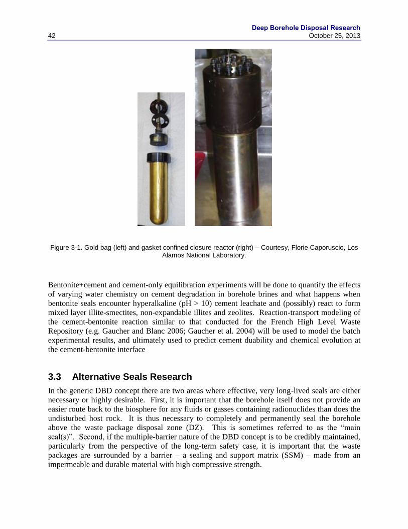
Deep Borehole Disposal Research
42 October 25, 2013
Figure 3-1. Gold bag (left) and gasket confined closure reactor (right) – Courtesy, Florie Caporuscio, Los Alamos National Laboratory.
Bentonite+cement and cement-only equilibration experiments will be done to quantify the effects
of varying water chemistry on cement degradation in borehole brines and what happens when
bentonite seals encounter hyperalkaline (pH > 10) cement leachate and (possibly) react to form
mixed layer illite-smectites, non-expandable illites and zeolites. Reaction-transport modeling of
the cement-bentonite reaction similar to that conducted for the French High Level Waste
Repository (e.g. Gaucher and Blanc 2006; Gaucher et al. 2004) will be used to model the batch
experimental results, and ultimately used to predict cement duability and chemical evolution at
the cement-bentonite interface
3.3 Alternative Seals Research
In the generic DBD concept there are two areas where effective, very long-lived seals are either
necessary or highly desirable. First, it is important that the borehole itself does not provide an
easier route back to the biosphere for any fluids or gasses containing radionuclides than does the
undisturbed host rock. It is thus necessary to completely and permanently seal the borehole
above the waste package disposal zone (DZ). This is sometimes referred to as the “main
seal(s)”. Second, if the multiple-barrier nature of the DBD concept is to be credibly maintained,
particularly from the perspective of the long-term safety case, it is important that the waste
packages are surrounded by a barrier – a sealing and support matrix (SSM) – made from an
impermeable and durable material with high compressive strength.
Deep Borehole Disposal Research October 25, 2013 43
The use of bentonite and cements for the main seal(s) has been discussed in Section 3.2, while
the use of bentonite, silica, graphite sand and other materials to surround and support the waste
packages has been described elsewhere (e.g., Brady et al. 2009; Sapiie & Driscoll 2009). This
section considers alternative and potentially better ways of achieving the necessary seals in both
contexts.
3.3.1 Borehole Sealing by Rock Welding
Oil, gas and geothermal energy wells are conventionally sealed in various ways for different
reasons with materials such as cement, concrete, clay, resin or asphalt/bitumen. Emplacing such
seals is not a simple matter and the difficulties of anchoring and sealing the casing to the wall
rock with cements in deep hydrocarbon and geothermal energy wells are well known. For DBD
the contact between the host rock and borehole seals must be as good as it can be and thus would
require removal of any casing or liner. Cutting the casing in or above the DZ and withdrawing it,
possibly for reuse, has been suggested (e.g., Gibb et al. 2012), but withdrawing such a length and
weight of casing is not an easy engineering option. A simpler, quicker and more cost effective
alternative would be to cut or grind away the casing over several meters of the borehole to
expose the rock where the seals are to be located.
Whatever material is used, the contact surface between the seal material and wall rock is a
potential zone of weakness and this could be exacerbated by longitudinal pressures in the
borehole, tectonic stresses or geochemical reactions between the seal material(s) and saline
groundwaters at elevated temperatures. Over time this could become a path of least resistance
for any fluids seeking to flow up or down the borehole.
A further complication arises from the existence of a DRZ around the borehole. In hard rocks
like granite this may be limited to tens of centimeters or less but it would be almost impossible to
get any sealing material, even where it is in pressurized contact with the wall rock, to penetrate
sufficiently far into the micro-fractures of the DRZ to render it impermeable to fluid flow. A
permeable DRZ is a potential bypass of the borehole seals for any radionuclide bearing fluids
and must be eliminated. Ways of reducing the impact of the DRZ, such as widening of the hole
and seal at intervals, have been suggested but are difficult to implement, with no guarantee of
success.
To create a better seal and eliminate the DRZ it has been proposed (Gibb et al. 2008a; 2008b;
2012) that a short length of the borehole, from which the casing has been removed, be backfilled
with finely crushed host rock that is then partially melted along with a significant thickness of
the wall rock by down-hole electrical heating. On cooling at an appropriate rate the melt
recrystallizes to effectively seal the hole and DRZ with material essentially identical to, and
continuous with, the host rock – a process that has been referred to as “rock welding”. This
could be repeated at intervals, determined by the geology, with the borehole between welds
being simply backfilled or, for further “insurance”, sealed with materials such as bentonite or
cement. The number, length and positioning of the rock welds can be varied to suit the borehole
geology. The ideal location for sealing the borehole is at the top of the DZ a short distance
above the uppermost waste package, thus sealing the hole as deep as possible to maximize the
geological barrier provided by DBD. Locating the seal(s) above the DZ could entail cutting
through concentric layers of casing but doing so in the upper part of the DZ requires removal of
only the DZ casing/liner.
Deep Borehole Disposal Research
44 October 25, 2013
Our approach to rock welding R&D began by developing a baseline engineering concept then,
using the heat flow software GRANITE (Gibb et al. 2008a; 2012), modeling various scenarios to
determine the 3-D distributions of temperature with time in and around the borehole. This
information is then combined with our knowledge of the melting and recrystallization of granitic
rock, refined as necessary, to ascertain the feasibility of creating rock welds of various lengths,
shapes and volumes. Data from this process are then used to inform the design of down-hole
electrical heaters and their deployment engineering. Beyond this, the concept would proceed to
larger scale testing under DBD conditions, including an investigation of properties such as the
mechanical strength of the seals, and ultimately to a demonstration in an actual borehole. Given
that the weld itself is holocrystalline rock identical in every respect to the host rock (except
possibly for minor differences in grain size) there should be no issues about the permeability or
longevity of the seal.
The baseline engineering concept involves backfilling the borehole with crushed host rock for a
few meters above the topmost waste package then inserting a bridge plug or simple cement plug.
Above this plug several meters of the DZ casing/liner is cut or ground away to expose the wall
rock and the hole is flushed with fresh water. A concentrated aqueous slurry of finely crushed
host rock is emplaced on top of the plug, filling the borehole almost to the top of the exposed
wall rock section, and the solids allowed to settle. A sacrificial electrical heating package, which
is connected to the surface by an umbilical cord, is then deployed on top of this and allowed to
sink a short way into the backfill. More crushed rock is added to fill the borehole for several
meters above the heater. A recoverable or sacrificial pressure seal, through which the umbilical
cord must pass, is set above the backfill. Power is then supplied to the heater at the required rate
to partially melt the enclosing backfill and host rock for an appropriate distance beyond the
borehole wall. From what is known about granitic systems (see below) this is likely to require
temperatures between 700ºC and 800°C. As melting proceeds, the viscous silicate magma flows
into any gaps, reducing the backfilled volume, causing the supercritical fluid phase to migrate
upwards and allowing the heater package to settle slightly. During this process the water in the
heated part of the borehole is anticipated to remain above its critical point and function as the
pressure medium for water-saturated melting. After a prescribed period (days to weeks), the
power to the heater is switched off or reduced in a controlled manner so the melt recrystallizes
completely by the time it reaches its solidus (~ 550ºC). This should take a matter of months.
It has been demonstrated (Attrill and Gibb 2003a; 2003b) that granite can be partially melted and
recrystallized under achievable conditions and on practical timescales in the context of DBD.
However, the work of Attrill and Gibb was carried out with a view to high-temperature DBD
(Gibb 2000; 2010) under pressures of 150 MPa (1.5 kbar), approximating to the ambient pressure
in the continental crust at a depth of 4 km. Until the borehole is sealed and the pressure gradually
recovers to ambient values, the pressure at any depth in the hole will be equal only to the weight
of the overlying fluid column, which in the case of 3 km of water would be around 29.5 MPa
(295 bar). To translate the temperatures generated in rock welding scenarios into meaningful
amounts of partial melting it is therefore necessary to repeat some of the experimental work of
Attrill and Gibb at lower pressures, the effects of which could raise the solidus by up to 50°C
(but probably less). Eventually, when a site and actual host rock have been selected, further
experimental work may be needed to refine the data for specific application.
Initial modeling focused on two basic cases – a 0.43 m diameter borehole (Arnold et al. 2011a)
and a 0.56 m diameter borehole (Gibb et al. 2012), both with a 2 m long heater having a diameter
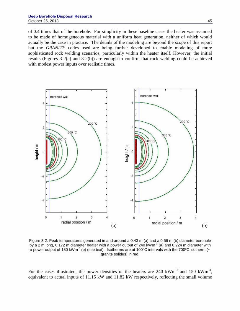
Deep Borehole Disposal Research October 25, 2013 45
of 0.4 times that of the borehole. For simplicity in these baseline cases the heater was assumed
to be made of homogeneous material with a uniform heat generation, neither of which would
actually be the case in practice. The details of the modeling are beyond the scope of this report
but the GRANITE codes used are being further developed to enable modeling of more
sophisticated rock welding scenarios, particularly within the heater itself. However, the initial
results (Figures 3-2(a) and 3-2(b)) are enough to confirm that rock welding could be achieved
with modest power inputs over realistic times.
(a) (b)
Figure 3-2. Peak temperatures generated in and around a 0.43 m (a) and a 0.56 m (b) diameter borehole by a 2 m long, 0.172 m diameter heater with a power output of 240 kWm
-3 (a) and 0.224 m diameter with
a power output of 150 kWm-3
(b) (see text). Isotherms are at 100°C intervals with the 700ºC isotherm (~ granite solidus) in red.
For the cases illustrated, the power densities of the heaters are 240 kWm-3
and 150 kWm-3
,
equivalent to actual inputs of 11.15 kW and 11.82 kW respectively, reflecting the small volume
Deep Borehole Disposal Research
46 October 25, 2013
of the heaters. In practice there would be benefits from using larger heaters but there is likely to
be an optimum balance between size and cost. The preliminary modeling has highlighted a
number of important issues that need to be addressed early in the rock welding R&D program.
These include:
For uniform heat outputs along the length of the heater, temperatures are lower at the top
and bottom than in the middle, and the zones of partial melting (the welds) have the
shapes indicated by the 700ºC isotherms in Figures 3-1(a) and 3-1(b). It is essential that
the melt zone completely encloses the heater, at least around its lower end, but it need
only extend far enough out into the backfill and wall rock at the extremities of the heater
to ensure the eventual weld has adequate mechanical strength. Provided the weld
eliminates the DRZ for a sufficient distance into the wall rock around the middle of the
heater, it need not do so along its full length, although the ideal would be for it to do so.
It is highly probable that sub-solidus recrystallization (annealing) would re-seal the DRZ
for some distance beyond the zone of actual melting but the extent and efficacy of such
sealing would have to be determined experimentally.
The shape and size of the weld can be controlled by varying the length and diameter of
the heater, the power input and the distribution of heat output within the heater. A more
extensive heat flow modeling study is required to ascertain the effects of such variations
and hence to determine how the most appropriate weld may best be generated. The
results would then inform the design of a practical heater to achieve such a weld.
It is clear from the baseline models that there is a possibility that temperatures inside the
heater could be unacceptably high from the perspective of the materials available to
construct it. To avoid this it will be necessary to consider a range of heater sizes,
geometries and differential vertical and radial power distributions within the heater.
More sophisticated heat flow modeling will be employed to evaluate the outcomes to
feed back into the evolution of heater design and use of the most appropriate materials.
The isotherms shown in Figures 3-1(a) and 3-1(b) are for the peak temperatures attained
in and around the borehole irrespective of the time taken to reach them. The further away
from the axis, the longer it takes to reach peak temperature and even at the borehole wall
these times can be months or even years (Gibb et al. 2008d). It would not be practical or
cost effective to go on supplying power to the heater for the long periods needed to
achieve peak temperatures and one objective of the R&D program is to devise heaters
that can generate the necessary zones of partial melting in relatively short periods (e.g., a
few weeks) before switching off or reducing the power. The next stage of the program
would consider such scenarios through the cooling interval to recrystallization.
The design, and eventual construction and testing, of electrical heaters for sealing the borehole
by rock welding are key aspects of the research program and the necessary electrical engineering
expertise is already involved through collaboration with the Department of Electrical &
Electronic Engineering at the University of Sheffield (UK). There is little doubt that suitable
heaters can be constructed to operate under the temperatures, pressures and chemical
environment of DBD. That the necessary levels of power can be supplied down-hole via an
umbilical cord is already known, e.g., by analogy with the electrical power supplied in this way
to remotely operated submersible vehicles that function at much greater depths and pressures
than in DBD. However, some development work may be required to adapt the technology used
Deep Borehole Disposal Research October 25, 2013 47
for down-hole electrical supplies in the drilling industry to the heavier duty umbilical cords
needed and their possible recovery.
Significant progress has been made with the rock welding research program and the essential
modeling work continues, as do the investigations of heater designs (with an early focus on
resistance heating) and deployment engineering. However, given the importance of sealing the
borehole to the viability of the DBD concept, more urgency needs to be attached to the project,
particularly the related experimental work on granite melting and the development, construction
and practical testing of down-hole heaters. Significant acceleration of these aspects would
require increased resources.
3.3.2 Waste Package Sealing and Waste Package Support Matrices
Deep boreholes are potentially suitable for the disposal of a wide variety of high-level wastes,
especially SNF, vitrified reprocessing waste and plutonium, and different variants of the DBD
concept have been proposed for specific types (e.g., Halsey et al. 1995; Gibb 2000; 2010; Hoag
2006; Gibb et al. 2008a; 2008c; Brady et al. 2009). Common to almost all of these are the use of
a cylindrical metal container and the fact that the wastes generate significant, but varying,
amounts of heat. For the concept to work the integrity of the containers need survive only until
the borehole is sealed above the DZ, but it would be beneficial to the safety case to prolong this
far into the future by protecting the containers from the saline groundwater. This could be
achieved by inserting an impermeable material – the SSM – into the annulus between the
container and the casing and, ideally, the gaps between the casing and borehole wall. Depending
on the material used, the SSM could also act as a barrier to the escape of any radionuclides that
eventually leak out of the container.
The primary function of the SSM is to prevent (or substantially delay) access of the groundwater
to the container, maintain reducing conditions and minimize corrosion, but it also has an
important secondary function. It can provide physical support to the waste packages to prevent
buckling and load damage to the containers arising from the weight of the overlying stack of,
potentially very heavy, waste packages. While it would be possible to design steel containers
with sufficient wall thickness to withstand these stresses it would be at a cost and with loss of
valuable disposal space. The use of a SSM with high compressive strength would eliminate the
need for this or the use of alternative methods of support, such as bridge plugs inserted at
intervals up the DZ.
3.3.2.1 High Density Support Matrices
For waste packages that generate high enough temperatures in the annulus between the container
and borehole wall the use of a novel high-density support matrix (HDSM) has been proposed
(Gibb et al. 2008b). Such packages could contain large numbers of used fuel rods, relatively
young used fuel, high burn-up fuel or any combination of these.
The HDSM consists of a Pb-based alloy in the form of a fine shot that is delivered in carefully
calculated amounts down the drill pipe (or deployment tube) following the emplacement of each
waste package, or batch of packages. The shot will run into all the spaces around and between
the packages and, via weight-reducing perforations in the DZ casing, into the gaps between the
Deep Borehole Disposal Research
48 October 25, 2013
casing and wall rock. Decay heat from the waste will soon cause the temperature to exceed the
solidus of the alloy (~ 185ºC), which will melt to a dense liquid and fill any remaining voids
between the container and the borehole wall. Over a period of years to decades, as the heat
output of the waste declines, the alloy will re-solidify, effectively “soldering” the packages into
the borehole. The use and workings of HDSMs have been discussed at length by Gibb et al
(2008b; 2012) and need not be described further here.
For waste packages that do not generate sufficient heat for the use of an alloy HDSM – which
could include much of the inventory of older UNF, especially where there is no fuel rod
consolidation – an alternative SSM is needed.
3.3.2.2 Cementitious Sealing and Support Matrices
In many mined repository concepts, such as the Swedish KBS-3, the primary barrier around the
SNF containers is a layer of bentonite and some DBD concepts have proposed similar material
be used to fill the annulus between the waste packages and the casing (e.g., Juhlin and
Sandstedt 1989; Arnold et al. 2011a). However, the successful use of a swelling clay like
bentonite as a SSM depends on its insertion under pressure into the annulus in a dehydrated state
so that subsequent hydration and swelling create a barrier impermeable to water. In a mined
repository this is best attempted by using pre-compacted and shaped blocks but the difficulties of
doing this are well known and it would be all but impossible to emplace dry bentonite around the
waste packages at the bottom of a water-filled borehole. Further, there is a temperature limit
(~ 100°C) above which the performance of bentonite as a seal is questionable. Consequently, an
alternative material for the SSM in DBDs not generating enough heat to use an alloy HDSM
would appear to be some form of cementitious grout, as suggested by Woodward–Clyde (1983).
Cements are relatively inexpensive, can be pumped or delivered down-hole in their more fluid
forms, remain soft long enough to be emplaced, have good compressive strengths when set and
excellent radiation shielding properties. Previously (Gibb et al. 2008a; 2008d; 2012), it was
suggested that the cement grout be “pumped down the borehole” via the drill pipe following the
deployment of the waste package(s). This assumes the grout would settle into the annulus
between the container and casing and, ideally, flow into the gaps between the casing and wall
rock before setting. However, the reality is that delivery and emplacement of the SSM are much
more complex engineering issues. It is well known that cementing operations are one of the
most difficult procedures that the drilling industry has to undertake and success at the depths and
pressures of a DBD system will require that a number of specific issues are resolved.
Preliminary studies suggest existing, commercially available, cement formulations used by the
hydrocarbon and geothermal energy industries (mainly for cementing casing) and their delivery
methods are unlikely to be suitable for SSM applications in DBD.
A research program underway at the University of Sheffield (UK) and funded by the Engineering
and Physical Sciences Research Council seeks to integrate borehole delivery engineering with a
study of cement formulations and their properties. The aim of this program is to come up with a
suitable formulation and delivery method such that a cement-based SSM can be successfully
implemented in the DBD system for low heat generating wastes. The program began with
modeling the dynamic thermal environment of a range of DBD concepts to determine the
“conditions of use,” i.e., the ranges of pressure, temperature and chemical conditions over which
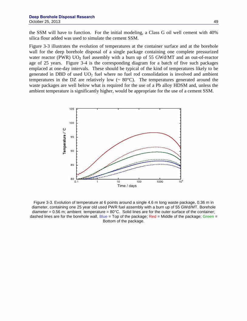
Deep Borehole Disposal Research October 25, 2013 49
the SSM will have to function. For the initial modeling, a Class G oil well cement with 40%
silica flour added was used to simulate the cement SSM.
Figure 3-3 illustrates the evolution of temperatures at the container surface and at the borehole
wall for the deep borehole disposal of a single package containing one complete pressurized
water reactor (PWR) UO2 fuel assembly with a burn up of 55 GWd/MT and an out-of-reactor
age of 25 years. Figure 3-4 is the corresponding diagram for a batch of five such packages
emplaced at one-day intervals. These should be typical of the kind of temperatures likely to be
generated in DBD of used UO2 fuel where no fuel rod consolidation is involved and ambient
temperatures in the DZ are relatively low (~ 80°C). The temperatures generated around the
waste packages are well below what is required for the use of a Pb alloy HDSM and, unless the
ambient temperature is significantly higher, would be appropriate for the use of a cement SSM.
Figure 3-3. Evolution of temperature at 6 points around a single 4.6 m long waste package, 0.36 m in diameter, containing one 25 year old used PWR fuel assembly with a burn up of 55 GWd/MT. Borehole diameter = 0.56 m; ambient temperature = 80°C. Solid lines are for the outer surface of the container;
dashed lines are for the borehole wall. Blue = Top of the package; Red = Middle of the package; Green = Bottom of the package.
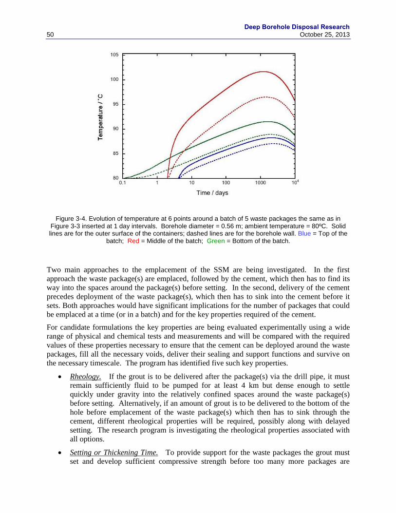
Deep Borehole Disposal Research
50 October 25, 2013
Figure 3-4. Evolution of temperature at 6 points around a batch of 5 waste packages the same as in Figure 3-3 inserted at 1 day intervals. Borehole diameter = 0.56 m; ambient temperature = 80ºC. Solid lines are for the outer surface of the containers; dashed lines are for the borehole wall. Blue = Top of the
batch; Red = Middle of the batch; Green = Bottom of the batch.
Two main approaches to the emplacement of the SSM are being investigated. In the first
approach the waste package(s) are emplaced, followed by the cement, which then has to find its
way into the spaces around the package(s) before setting. In the second, delivery of the cement
precedes deployment of the waste package(s), which then has to sink into the cement before it
sets. Both approaches would have significant implications for the number of packages that could
be emplaced at a time (or in a batch) and for the key properties required of the cement.
For candidate formulations the key properties are being evaluated experimentally using a wide
range of physical and chemical tests and measurements and will be compared with the required
values of these properties necessary to ensure that the cement can be deployed around the waste
packages, fill all the necessary voids, deliver their sealing and support functions and survive on
the necessary timescale. The program has identified five such key properties.
Rheology. If the grout is to be delivered after the package(s) via the drill pipe, it must
remain sufficiently fluid to be pumped for at least 4 km but dense enough to settle
quickly under gravity into the relatively confined spaces around the waste package(s)
before setting. Alternatively, if an amount of grout is to be delivered to the bottom of the
hole before emplacement of the waste package(s) which then has to sink through the
cement, different rheological properties will be required, possibly along with delayed
setting. The research program is investigating the rheological properties associated with
all options.
Setting or Thickening Time. To provide support for the waste packages the grout must
set and develop sufficient compressive strength before too many more packages are

Deep Borehole Disposal Research October 25, 2013 51
emplaced on top. Given that deployments could be less than 24 hours apart (see
Section 3.4.2), this could require quite rapid setting. On the other hand, the grout must
not set before penetrating and completely filling the annulus around the package (and,
ideally, as much of the gap between the casing and wall rock as possible). This might
necessitate delaying of a normally rapid set through the use of special formulations or
additives, or by developing cement that does not set until a critical temperature is
attained. These seemingly conflicting requirements require a thorough understanding and
careful control of setting time and other properties.
Hardening & Mechanical Properties. Ensuring the containers can withstand the load
stresses in the borehole, especially during filling of the DZ, is a key safety requirement of
the concept. Depending on the weights of the packages and the inherent strength of the
containers, the grout might be required to have quite high compressive strength when set.
Also, if the sealing function is not to be jeopardized, the material used must have a
relatively low thermal expansion coefficient, although this is not likely to be a major
problem with most cement formulations.
Geochemical Reactions. The grout could react with the container, casing, host rock or
groundwater under the high pressure, temperature and chemical conditions encountered.
Any such reactions are likely to be minor and of significance only to the long-term
containment (sealing) function of the grout but, if they did occur rapidly, they could
affect the setting process and mechanical properties of the cement and so must be
understood and quantified.
Durability. Once the borehole is sealed above the DZ (by the main seal(s)), it is not
essential that the grout continues to support the waste packages, protect them from
groundwater and function as a barrier to radionuclide escape. However, from the
perspective of the long-term safety case, the longer it continues to fulfill these functions
the better. It is therefore important that the durability of the cement and its leaching
properties in saline solutions are known and understood.
Evaluation of the candidate cements in the research program against the above guidelines may
reveal a suitable material, but it appears likely that improvements will be necessary to develop a
formulation that is fit for purpose. Should no such formulation emerge, the project will attempt
to develop one that can be taken forward to an experimental testing program and, eventually, to
trials in a demonstration borehole, pending additional R&D funding.
3.4 Waste Package Deployment
It is generally assumed that in DBD the waste packages would be deployed singly but it has been
suggested that they might be deployed in small batches, separated by time intervals and/or
physical spacers (Gibb et al. 2008a ) or even in long strings of up to 40 with a total length of
nearly 200 m (Arnold et al. 2011a). Emplacement is usually taken to be by lowering on the end
of the drill pipe using the drilling rig or a lighter emplacement rig but other, potentially more
efficient, mechanisms such as wireline and coiled tubing have been considered (Beswick 2008)
and are discussed further below.
For economic, operational and practical reasons, DBD requires that the waste packages can be
emplaced at rates of the order of one per day. While the deployment strategy will depend on a
Deep Borehole Disposal Research
52 October 25, 2013
number of things, such as the weight of the packages, their heat output, the mechanism
employed, the capacity of the emplacement rig, etc., the two main factors controlling the rate at
which waste packages can be deployed in DBD are
The rate at which the packages can be delivered to the well-head and readied for
emplacement, and,
The time taken to deliver the package down-hole to the DZ and recover the delivery
equipment ready for the next emplacement.
3.4.1 Emplacement Rates
For practical reasons related to the emplacement mechanisms, waste packages can only be
deployed in DBD by lowering them under tension to the DZ. There can be no question of
forcing or pushing them down the borehole, although recoverable additional weight could be
added above the package(s) to speed up descent. This places an upper limit on the rate at which
they can be lowered equivalent to the rate at which the package(s) would descend in free fall
under the influence of gravity alone. This free fall velocity is also an important parameter in the
context of accidental release of a waste package during deployment and the operational safety
case.
Calculation of the sinking velocity of a cylindrical package in a fluid-filled borehole is not a
simple application of Stoke’s Law as the “piston effect” or “hydrodynamic damping (or
braking)” becomes increasingly important as the diameter of the package approaches that of the
borehole or, in the case of DBD, the casing/liner. A series of small-scale experiments have been
undertaken to evaluate the effect of the various parameters on the terminal velocity of a metal
cylinder sinking in a water-filled tube. By far the most important factor controlling the sinking
rate is the clearance between the cylinder (waste package) and the tube (casing) but there is also
a relationship between the mass of the cylinder and velocity.
Clearance between the waste package and casing is a crucial parameter for DBD. On the one
hand it needs to be as small as possible to minimize the cost of the borehole and maximize the
volume of waste that can be put in the container (depending on whether it is the diameter of the
container or that of the borehole that is the controlling factor). On the other, it must be kept large
enough to eliminate any risk of jamming or damage to the container(s) during descent to the DZ.
Suggested values for a suitable clearance tend to be between 2 and 3 cm (Arnold et al. 2011a;
Gibb et al. 2012) but the optimum clearance for reliability of emplacement can only be evaluated
meaningfully in a full scale demonstration borehole.
Experimental results and calculations reveal that there is a strong linear relationship between
clearance and sinking velocity with the velocity tending to zero as the clearance becomes small.
Also, as the mass, volume and density of the package increase, so too does the sinking velocity
for any given clearance, but this effect is non-linear and becomes less marked as mass and
density increase. Nuclear waste packages for DBD of SNF are likely to have masses between
2,000 kg and 4,700 kg, depending on their construction and contents and it can be estimated that
the free fall velocity of such packages in a borehole with a package outside diameter (OD) to
casing inside diameter (ID) ratio of 0.85 (Arnold et al. 2011a; Gibb et al. 2012) will lie in the
range 0.5 to 1.5 m/sec. For a 4 km deep DBD demonstration this suggests it is likely to prove
impossible to deliver packages to the DZ in less than about one hour, although the perforations in
Deep Borehole Disposal Research October 25, 2013 53
the DZ casing/liner would raise the limiting velocity for the last part of the emplacement. The
extent of the perforation effect, like the use of any deployment fluid other than water, can only
be evaluated properly in a full scale demonstration borehole. In practice, the limiting factor on
the deployment rate of waste packages will almost certainly be the mechanism of emplacement,
none of which are likely to achieve such rapid descent (see Section 3.4.2).
The rate at which waste packages are emplaced could have implications for the possibility of
deploying them in long strings, particularly for high heat generating materials such as relatively
young reprocessing wastes and UNF. If it is assumed that the packages are delivered to the DBD
site in air-cooled or refrigerated containers, the outside surface of the package should not be
significantly above ambient temperature when it is placed into the borehole fluid at the top of the
hole. If the package then descends the borehole at a rate of hundreds of m/hr, the flow of fluid
past the package should prevent its outer surface temperature from increasing significantly
before it reaches a safe depth. If, however, the packages remain immersed in the near-static fluid
at the top of the hole for a protracted period while a long deployment string is assembled, there is
a risk that the boiling point of the fluid at near-atmospheric pressure could be exceeded with
serious consequences. Heat flow modeling (e.g., Gibb et al. 2008d, fig. 5) has shown that for
batches/strings of a few containers of relatively young vitrified waste or SNF the temperatures on
parts of the package surfaces can increase by over 100ºC in a matter of days when stationary at
the bottom of the borehole. The same would be true at the top of the hole where the borehole
fluid could boil and create problems. This could place constraints on the time available for
assembly of container strings or on the contents of the packages suitable for deployment in this
way.
3.4.2 Emplacement Mechanisms
The borehole itself must be constructed and lined such that irregularities or curvature will not
affect the emplacement of waste packages either individually or in strings. With the diameter
and well construction methods proposed, this should not be an issue but, prior to emplacement,
the borehole would be checked by running a caliper and/or a dummy waste package.
Four principle emplacement mechanisms could be considered:
Free fall
Wireline
Use of conventional oilfield drill pipe
Use of conventional oilfield coiled tubing
3.4.2.1 Free Fall
As reported above, the “free fall” scenario needs to be considered even if only for the remote
possibility that a waste package becomes detached from the deployment equipment. This is not
an uncommon means of down-hole emplacement in drilling operations and it is the standard
method when using wireline core barrels whereby the inner barrel is replaced by free fall to latch
into the outer barrel each sample trip. Rates of decent would depend on a number of factors
including the borehole fluid viscosity and the clearance between the waste package and the
casing (see Section 3.4.1). However, for deep borehole disposal free fall should not be employed
as there is no control on the emplacement.
Deep Borehole Disposal Research
54 October 25, 2013
3.4.2.2 Wireline
The use of a wireline to lower the package has the attraction of simplicity, but its use would limit
the weight of the package and it provides less control than the use of drill pipe or coiled tubing.
It also carries an increased risk of “hang ups” leading to recovery problems that could be deemed
inappropriate for disposal of radioactive wastes. There are two types of line, referred to as “slick
line” and “wireline with electrical conductors”. Slickline is just a braided wireline in varying
sizes. Depth control is maintained at the surface. A wireline with electrical conductors on the
other hand allows a waste package release mechanism to be triggered and monitoring data, such
as the necessary depth measurements, to be transmitted.
All forms of wireline will stretch much more under load than any metallic tubing and so depth
control by reference to casing collar depths previously recorded during installation is essential.
The wireline winch system can deliver up to 6000 m/hr but the actual speed of deployment,
which will depend on other factors such as the limiting velocity (see above), is likely to be much
less. Units are available with combined hydraulic cranes, requiring only a small site set-up area
around the borehole.
3.4.2.3 Conventional Oilfield Drill Pipe
This is the traditional means of working within a borehole. It requires a “drilling” or “workover”
rig and a relatively large site area. Drill pipe comes in various diameters and steel strengths in
9.45 m or 12 m standard lengths. Deployment with drill pipe is a discontinuous process, in that
each length of drill pipe has to be added or removed with each connection being screwed in or
out of the next. This is the standard method for drilling and the rigs include various devices for
making up, breaking out and torquing the drill pipe to the correct values.
Speed of deployment depends on the height of the rig and whether it is manual or automatic.
The traditional “triples” rigs lower or pull three lengths of 9.45 m drill pipe each time (i.e.,
~28 m) and rack the pipe stands back in the mast or derrick. There are also a smaller “doubles”
variant that pulls two lengths of pipe (~ 19 m) and also “super-singles” rigs that handle one
length of 12 m drill pipe.
With conventional rigs this process requires a “derrick hand” working high in the mast to rack
the pipe back into finger boards designed to accommodate the size of pipe being used. However,
modern rig designs driven by health and safety concerns have eliminated this practice, and hence
the need for a person to work in an exposed position, through the use of robotics with various
types of pipe handling devices available. Deployment speeds (or “trip speeds”) range from 500
m/hr to 600 m/hr for automated systems to typically 1000 m/hr in a cased hole with the best
“driller-derrick hand team”. The latter requires the team to work efficiently together to enable
such fast tripping. For DBD an automatic system would be preferable on safety grounds and
modern rigs are becoming more and more sophisticated with the elimination of most of the
manual operations.
Using drill pipe, the waste package release mechanism would have to be mechanical, which
introduces some uncertainty, but a suitable system could be engineered. Depth control would be
through the normal practice of surface monitoring as the drill pipe is run.
Deep Borehole Disposal Research October 25, 2013 55
3.4.2.4 Conventional Oilfield Coiled Tubing
In recent years the development of coiled tubing systems has been rapid and these systems are
now used for drilling, well intervention, logging and well completion operations. A wide range
of equipment is available. New systems include electrical conductors through the endless tube
allowing commands for release mechanisms and data transmission. The equipment is widely
used in different sizes and to depths well in excess of the 4 to 5 km proposed for DBD.
Deployment speeds could be 2000 m/hr to 3000 m/hr with a package release mechanism
triggered through some of the conductors in the tubing and data acquisition possible through
others. The surface set up would be relatively small and hence more cost effective than
maintaining a drilling rig on site at the DBD location. Using this method the risk of radiation
exposure to personnel would be kept to a minimum.
The “round trip” for the emplacement of waste packages is not simply a matter of down-hole and
return travel times (Schlumberger, 2013). It must also allow for surface operations like attaching
the package(s), depth checks and the package release (and any other) procedures that have to be
undertaken in the DZ. Conservative estimates of the time required for a single emplacement trip
in a 4 km borehole using each of the possible mechanisms are: 8 hours (wireline); 18 hours (drill
pipe) and 8 hours (coiled tube). These times for wireline and coiled tube emplacement offer
scope for improvement with practice, but at some increased risk, especially for the former where
fast running can lead to entanglements. Emplacement of very long and heavy strings of waste
packages may require the use of drill pipe but the various advantages of coiled tubing could
warrant reconsideration of this long-string strategy towards individual waste package
emplacement or smaller strings.
The basic equipment and systems for all of the above options are readily available. There would
necessarily have to be some development of nonstandard items, such as the waste package
release mechanisms, but development costs would be minimal. Also, consideration would need
to be given to the selection of mechanisms and equipment that offer the minimum risk of
exposure to people at and around the site.
It is apparent from the study reported above that emplacement of waste packages via the coiled
tubing method could emerge as the preferred option and be much more cost effective than the
use of a drilling or workover rig. Ideally, the waste disposal organization would own a purpose-
designed equipment package so the cost spread over a substantial disposal program would be
relatively low. However, for a demonstration borehole or pilot scheme, it would be preferable to
utilize the equipment readily available in the drilling industry.
3.5 Seals Demonstration Testing Plan
Ultimately candidate seals and their emplacement must be tested under downhole conditions. In
particular, in situ permeability and strength must be measured. This will be done at the
demonstration borehole by emplacing constructed seals at depths greater than 2 km and
performing standard strength/permeability tests and drilling through the seal after testing. In situ
strength will be measured by applying vertical loads via the drill rig itself, or via application of a
packer pressure system. In situ permeability testing will be done using a packer system. Seal
materials to be tested include traditional materials such as cement and bentonite as well as rock
welds.

Deep Borehole Disposal Research
56 October 25, 2013
Verifying emplaceability of seals at > 2 km depth will be central to the seals demonstration
effort. Multiple emplacement approaches will be tested for each material, including rock welds,
to establish depth effectiveness. For example, bentonite emplacement by containers, plugs, or
perforated tubes will be tested. Cement emplacement by balanced plug, cement squeeze, dump
bailer, and two plug methods will be tested. Field testing of seals will be done in the final two
years of the borehole demonstration.
Deep Borehole Disposal Research October 25, 2013 57
4. SAFETY FRAMEWORK AND RD&D NEEDS
4.1 Identification of RD&D Needs for Demonstration of Safety
The approach to identifying the science and engineering activities RD&D to support the DBD
demonstration first requires identifying a list of potential candidate activities, which are relevant
to the DBD demonstration and its objectives and then evaluating this list of potential activities
against a set of metrics. This evaluation indicates those activities that best contribute to the
success of the DBD demonstration and an understanding of DBD.
The identification step involves three sub-steps: 1) identify objectives of the deep borehole
disposal demonstration, 2) identify the relevant features, events, and process associated with
deep borehole disposal, and 3) identify potential science and engineering activities needed for the
demonstration). These sub-steps are described below.
Deep Borehole Disposal Demonstration Objectives
The DBD demonstration will help resolve key uncertainties about the DBD of nuclear waste and
will provide information that permits a comprehensive evaluation of the potential for licensing
and deploying DBD for SNF and HLW. This is done in the absence of using nuclear materials.
The objectives and tasks of the DBD demonstration have been described previously, (DOE,
2012a), and are briefly summarized below. The four primary objectives are:
1) Demonstrate the feasibility of characterizing and engineering deep boreholes,
2) Demonstrate processes and operations for safe waste emplacement down hole,
3) Confirm geologic controls over waste stability, and
4) Demonstrate safety and practicality of licensing.
The four major tasks that address these goals are:
1) Demonstration Site Selection – This task will locate the demonstration borehole at a site
that is representative of the geology and other characteristics that would be encountered if
DBD would be implemented in the future. In addition to establishing site selection
guidelines, this task also ensures that regulatory permits for borehole construction and
demonstration are in place for implementing the DBD demonstration project.
2) Borehole Drilling and Construction – This task will develop a borehole design, establish
borehole requirements, implement a contract for construction of the borehole, and ensure
that the drilled and completed borehole meets requirements.
3) Science Thrust – This task will identify and resolve data gaps in the deep borehole
geological, hydrological, chemical, and geophysical environment that are important to
post-closure safety of the system, materials performance at depth, and construction of the
disposal system. This task uses a systematic approach to prioritize data gaps and methods
for resolving them. This activity will also perform safety analyses demonstrating the
safety of the DBD concept for disposal of SNF and HLW.

Deep Borehole Disposal Research
58 October 25, 2013
4) Engineering Demonstration – This task will confirm the capacity and feasibility of the
DBD concept and will include canister emplacement operations (in the borehole),
canister transference, canister stringing, and operational retrieval. This task will also
include design and fabrication of test canisters and other equipment unique to the
demonstration. This task will also provide all documentation confirming the safety,
capacity, and feasibility of the DBD concept.
FEPs Relevant to Deep Borehole Disposal
A list of potential activities relevant to the DBD demonstration is created by first examining the
FEPs that are relevant to the disposal of SNF and HLW in deep boreholes. In Brady et al. (2009)
an initial evaluation of FEPs relevant to DBD was conducted. A comprehensive list of 374 FEPs
relevant to geologic disposal was examined for relevancy to DBD. In addition to relevancy to
DBD, the FEPs were also identified as likely to be excluded from consideration or included in
the DBD performance assessment. While this determination is based on scientific judgment, no
formal FEPs screening of these FEPs has been conducted and the assessment should be
considered as preliminary and requiring supporting justifications. FEPs that are excluded require
sufficient justification for their exclusion while FEPs that are included require a sufficient
understanding so that they are properly captured and parameterized.
In the FEPs analysis of Brady et al. (2009) excluded FEPs are further qualified according to the
level of effort required to make the exclusion argument. Three levels are defined: 1) technical or
regulatory basis is readily available, 2) some additional technical work likely is needed, and 3) a
significant amount of work is potentially needed. For included FEPs three levels of effort are
defined to categorize the level of effort needed to support the inclusion into the PA model: 1)
indicates that this is a normal part of modeling, 2) indicates that this is a significant aspect of the
modeling, and 3) indicates possible modeling challenges may be encountered.
Identify Science and Engineering Activities Relevant to DBD Demonstration
In the Deep Borehole RD&D Roadmap (DOE 2012a), a preliminary association of potential
DBD demonstration activities to the FEPs was presented as an example. This is expanded and
re-evaluated in this work. Each of the 374 FEPs identified in Brady et al. (2009) is evaluated for
information needs and, if applicable, associated scientific and engineering activities capable of
supporting those needs.
Examination of the potential science and engineering activities and the FEPs suggest some
commonalities, which help to facilitate the association of science and engineering activities with
FEPs. These groupings provide for some consistency in making the associations and also point
out the amount of “coverage” the science and engineering activities have in particular technical
areas of interest.
A total of 45 science and engineering activities are identified. Collectively these activities
address 185 of the 374 FEPs. Additionally, it is readily apparent that many of the science and
engineering activities address multiple FEPs and multiple science and engineering activities
address many of the same FEPs. This apparent redundancy can provide cross-checking of the
data collected or can be incorporated as a metric into the prioritization of the activities. The
Deep Borehole Disposal Research October 25, 2013 59
results of the association should still be considered as preliminary because there is a fair amount
of subjectivity in assigning of activities to FEPs and more than one opinion should be elicited.
This arises because decisions on the degree of relevancy of the association are required.
4.2 Technical Basis for Prioritization in the Safety Framework
The technical bases for the safety framework have been updated or reevaluated relative to
previous studies (see Section 4.3) with regard to thermally driven groundwater flow, nuclear
criticality and operational safety.
4.2.1 Site-Scale Thermal-Hydrologic Effects
The objectives of the modeling described in this section are to update the thermal-hydrologic
model and incorporate more realistic geological and hydrogeological conditions in analyses of
thermal-hydrologic effects in deep borehole disposal of used nuclear fuel. Thermal-hydrologic
analyses are updated to a reference design for the disposal system (Arnold et al. 2011a) and to
examine sensitivities to the number of boreholes in a disposal system array. Additional realism
is included with regard to geological layering, variability in model parameters with depth, and
coupling of salinity and fluid-density stratification with thermal-hydrologic processes.
Simulated thermally driven, vertical groundwater flow rates are important inputs to disposal
system model analyses of deep borehole repository safety, which can be updated using the
results from these analyses.
Numerous design alternatives exist for a deep borehole disposal system, including borehole
depth, diameter, waste canister size, borehole spacing, borehole array size, waste characteristics,
and thermal output. In addition, geological and hydrogeological characteristics of the site may
vary significantly among potential disposal sites. The analyses for this study were conducted
using reasonable disposal system design options and geological conditions that are representative
of a stable continental interior and favorable to waste isolation.
The reference deep borehole disposal system design used in this analysis is that developed in a
study on feasible design options, general operational procedures, and costs (Arnold et al. 2011a).
The reference design consists of a vertical, telescoping borehole design with a 43 cm (17 inch)
diameter in the waste disposal zone from 3,000 m to 5,000 m depth. Waste canisters are
constructed of carbon steel with a wall thickness capable of withstanding hydrostatic pressures,
temperatures, and mechanical stress from overlying canisters during the emplacement and near-
term post-closure times. Waste canisters would be emplaced in strings of approximately 200 m
length, separated by borehole bridge plugs to support the weight of each canister string.
Canisters for the disposal of used nuclear fuel would each contain about 367 PWR fuel rods from
the disassembly and consolidation of nuclear fuel assemblies. Used fuel thermal output
characteristics are for average PWR fuel (Carter et al. 2011). Following waste canister
emplacement, the borehole casing would be removed from the upper 3,000 m of the borehole
and a series of seals would be emplaced. Multiple boreholes would be constructed in an
orthogonal array with 200 m spacing between the boreholes.
The geological system is assumed to consist of crystalline basement rocks overlain by 1,500 m of
sedimentary rocks. The crystalline rocks are assumed to be granite or felsic metamorphic rocks
Deep Borehole Disposal Research
60 October 25, 2013
with a similar mineralogical composition. The sedimentary strata consist of horizontal layers of
sandstone, shale, limestone, and dolomite. Paleozoic and Mesozoic-age sedimentary units
dominated by these rock types cover large areas of the continental interior of North America.
Ambient hydrogeological conditions consist of shallow fresh groundwater underlain by stratified
conditions of increasingly saline brines with depth. Small-scale, primarily horizontal,
groundwater flow may occur in the upper few hundred meters of the sedimentary cover, but no
large-scale, regional groundwater flow system exists in the crystalline basement rocks.
Furthermore, it is assumed that overpressured conditions resulting from compaction of sediments
or from anomalously high heat flow do not exist. Consequently, it is assumed that there is no
ambient vertical gradient in fluid potential within the hydrogeological system.
4.2.1.1 Model Setup
The thermal-hydrologic model for the deep borehole disposal system is constructed to provide
simulated temperature near the borehole and groundwater flow rates within the borehole and
disturbed rock zone, as functions of time. The model domain is large enough to minimize the
impacts of lateral boundary conditions on the simulation results near and in the boreholes. As
indicated by the results, the grid resolution is sufficiently fine near the boreholes to provide
reasonably accurate simulated temperatures near the boreholes and to capture the effects of
thermally driven flow near and within the boreholes. However, the grid resolution near the
boreholes does not capture the individual components of the engineered disposal system, such as
waste canisters, borehole grout, and individual fuel rods. Consequently, the grid resolution is not
sufficient to provide accurate estimates of waste canister and fuel temperatures. The thermal-
hydrologic model domain uses quarter symmetry, with no-flow boundaries on two sides, to
reduce the overall grid size and computational cost of the simulations.
The model grid was constructed using the CUBIT software code (SNL 2012). The 3D model
domain is 10 km 10 km in the horizontal directions and 7 km deep, for a total simulation
domain of 20 km 20 km 7 km when accounting for the quarter symmetry lateral boundary
conditions. The grid is an unstructured hexahedral mesh with progressive grid refinement
around the borehole array and individual boreholes. The horizontal grid spacing is less than 1 m
at the boreholes and expands to 200 m spacing outward from the borehole array. The vertical
grid spacing is uniform 100 m. The grid can accommodate simulation of up to 81 boreholes.
This grid consists of 866,910 nodes and is illustrated in Figure 4-1.
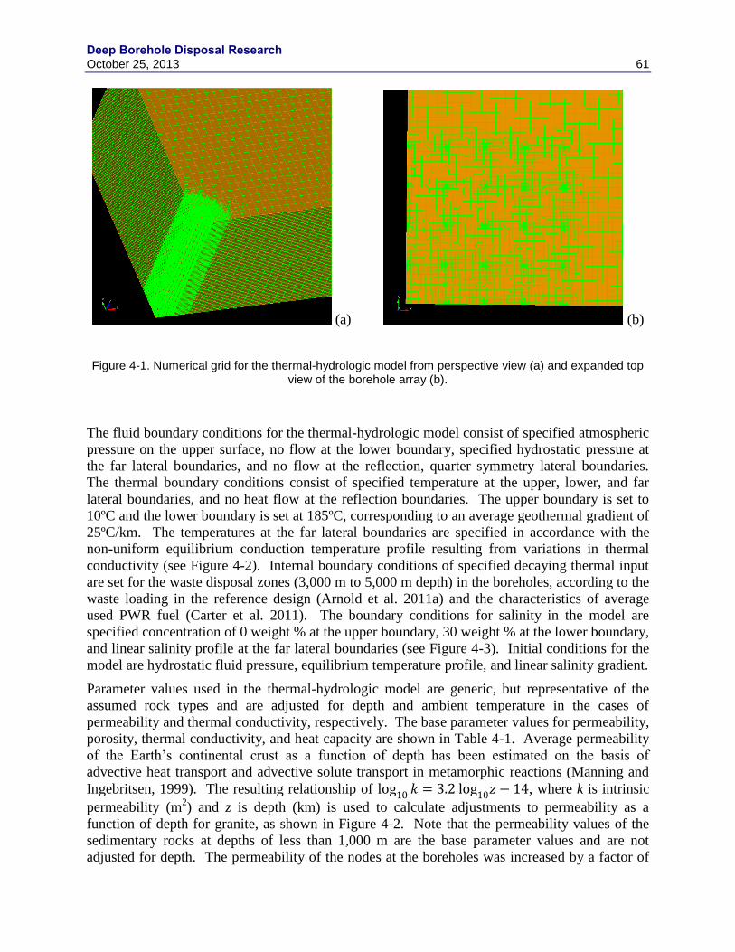
Deep Borehole Disposal Research October 25, 2013 61
(a) (b)
Figure 4-1. Numerical grid for the thermal-hydrologic model from perspective view (a) and expanded top view of the borehole array (b).
The fluid boundary conditions for the thermal-hydrologic model consist of specified atmospheric
pressure on the upper surface, no flow at the lower boundary, specified hydrostatic pressure at
the far lateral boundaries, and no flow at the reflection, quarter symmetry lateral boundaries.
The thermal boundary conditions consist of specified temperature at the upper, lower, and far
lateral boundaries, and no heat flow at the reflection boundaries. The upper boundary is set to
10ºC and the lower boundary is set at 185ºC, corresponding to an average geothermal gradient of
25ºC/km. The temperatures at the far lateral boundaries are specified in accordance with the
non-uniform equilibrium conduction temperature profile resulting from variations in thermal
conductivity (see Figure 4-2). Internal boundary conditions of specified decaying thermal input
are set for the waste disposal zones (3,000 m to 5,000 m depth) in the boreholes, according to the
waste loading in the reference design (Arnold et al. 2011a) and the characteristics of average
used PWR fuel (Carter et al. 2011). The boundary conditions for salinity in the model are
specified concentration of 0 weight % at the upper boundary, 30 weight % at the lower boundary,
and linear salinity profile at the far lateral boundaries (see Figure 4-3). Initial conditions for the
model are hydrostatic fluid pressure, equilibrium temperature profile, and linear salinity gradient.
Parameter values used in the thermal-hydrologic model are generic, but representative of the
assumed rock types and are adjusted for depth and ambient temperature in the cases of
permeability and thermal conductivity, respectively. The base parameter values for permeability,
porosity, thermal conductivity, and heat capacity are shown in Table 4-1. Average permeability
of the Earth’s continental crust as a function of depth has been estimated on the basis of
advective heat transport and advective solute transport in metamorphic reactions (Manning and
Ingebritsen, 1999). The resulting relationship of , where k is intrinsic
permeability (m2) and z is depth (km) is used to calculate adjustments to permeability as a
function of depth for granite, as shown in Figure 4-2. Note that the permeability values of the
sedimentary rocks at depths of less than 1,000 m are the base parameter values and are not
adjusted for depth. The permeability of the nodes at the boreholes was increased by a factor of
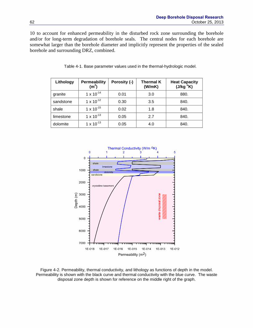
Deep Borehole Disposal Research
62 October 25, 2013
10 to account for enhanced permeability in the disturbed rock zone surrounding the borehole
and/or for long-term degradation of borehole seals. The central nodes for each borehole are
somewhat larger than the borehole diameter and implicitly represent the properties of the sealed
borehole and surrounding DRZ, combined.
Table 4-1. Base parameter values used in the thermal-hydrologic model.
Lithology Permeability (m
2)
Porosity (-) Thermal K (W/mK)
Heat Capacity (J/kg
oK)
granite 1 x 10-14
0.01 3.0 880.
sandstone 1 x 10-12
0.30 3.5 840.
shale 1 x 10-15
0.02 1.8 840.
limestone 1 x 10-13
0.05 2.7 840.
dolomite 1 x 10-13
0.05 4.0 840.
Figure 4-2. Permeability, thermal conductivity, and lithology as functions of depth in the model. Permeability is shown with the black curve and thermal conductivity with the blue curve. The waste
disposal zone depth is shown for reference on the middle right of the graph.
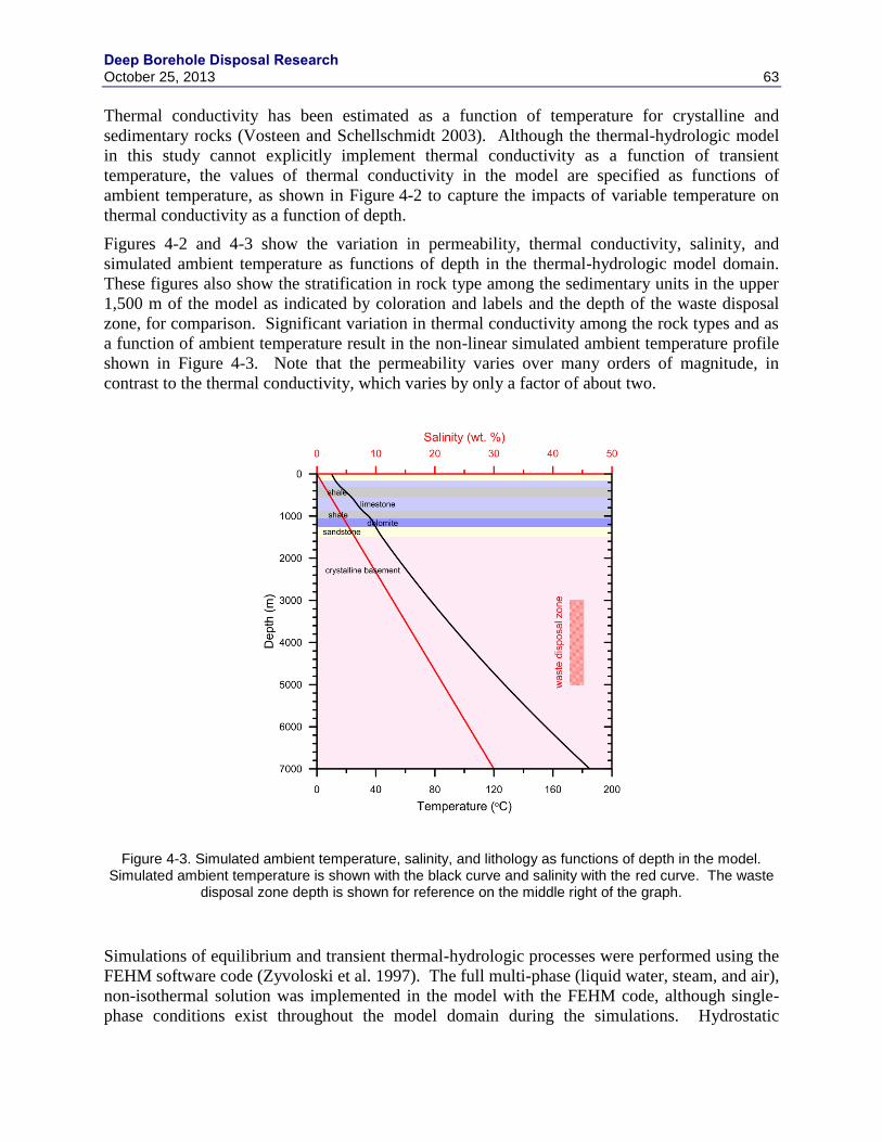
Deep Borehole Disposal Research October 25, 2013 63
Thermal conductivity has been estimated as a function of temperature for crystalline and
sedimentary rocks (Vosteen and Schellschmidt 2003). Although the thermal-hydrologic model
in this study cannot explicitly implement thermal conductivity as a function of transient
temperature, the values of thermal conductivity in the model are specified as functions of
ambient temperature, as shown in Figure 4-2 to capture the impacts of variable temperature on
thermal conductivity as a function of depth.
Figures 4-2 and 4-3 show the variation in permeability, thermal conductivity, salinity, and
simulated ambient temperature as functions of depth in the thermal-hydrologic model domain.
These figures also show the stratification in rock type among the sedimentary units in the upper
1,500 m of the model as indicated by coloration and labels and the depth of the waste disposal
zone, for comparison. Significant variation in thermal conductivity among the rock types and as
a function of ambient temperature result in the non-linear simulated ambient temperature profile
shown in Figure 4-3. Note that the permeability varies over many orders of magnitude, in
contrast to the thermal conductivity, which varies by only a factor of about two.
Figure 4-3. Simulated ambient temperature, salinity, and lithology as functions of depth in the model. Simulated ambient temperature is shown with the black curve and salinity with the red curve. The waste
disposal zone depth is shown for reference on the middle right of the graph.
Simulations of equilibrium and transient thermal-hydrologic processes were performed using the
FEHM software code (Zyvoloski et al. 1997). The full multi-phase (liquid water, steam, and air),
non-isothermal solution was implemented in the model with the FEHM code, although single-
phase conditions exist throughout the model domain during the simulations. Hydrostatic
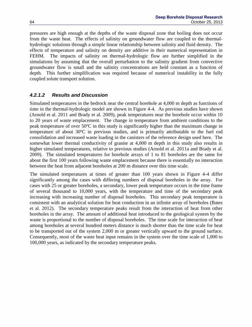
Deep Borehole Disposal Research
64 October 25, 2013
pressures are high enough at the depths of the waste disposal zone that boiling does not occur
from the waste heat. The effects of salinity on groundwater flow are coupled to the thermal-
hydrologic solutions through a simple linear relationship between salinity and fluid density. The
effects of temperature and salinity on density are additive in their numerical representation in
FEHM. The impacts of salinity on thermal-hydrologic flow are further simplified in the
simulations by assuming that the overall perturbation to the salinity gradient from convective
groundwater flow is small and the salinity concentrations are held constant as a function of
depth. This further simplification was required because of numerical instability in the fully
coupled solute transport solution.
4.2.1.2 Results and Discussion
Simulated temperatures in the bedrock near the central borehole at 4,000 m depth as functions of
time in the thermal-hydrologic model are shown in Figure 4-4. As previous studies have shown
(Arnold et al. 2011 and Brady et al. 2009), peak temperatures near the borehole occur within 10
to 20 years of waste emplacement. The change in temperature from ambient conditions to the
peak temperature of over 50ºC in this study is significantly higher than the maximum change in
temperature of about 30ºC in previous studies, and is primarily attributable to the fuel rod
consolidation and increased waste loading in the canisters of the reference design used here. The
somewhat lower thermal conductivity of granite at 4,000 m depth in this study also results in
higher simulated temperatures, relative to previous studies (Arnold et al. 2011a and Brady et al.
2009). The simulated temperatures for borehole arrays of 1 to 81 boreholes are the same for
about the first 100 years following waste emplacement because there is essentially no interaction
between the heat from adjacent boreholes at 200 m distance over this time scale.
The simulated temperatures at times of greater than 100 years shown in Figure 4-4 differ
significantly among the cases with differing numbers of disposal boreholes in the array. For
cases with 25 or greater boreholes, a secondary, lower peak temperature occurs in the time frame
of several thousand to 10,000 years, with the temperature and time of the secondary peak
increasing with increasing number of disposal boreholes. This secondary peak temperature is
consistent with an analytical solution for heat conduction in an infinite array of boreholes (Bates
et al. 2012). The secondary temperature peaks result from the interaction of heat from other
boreholes in the array. The amount of additional heat introduced to the geological system by the
waste is proportional to the number of disposal boreholes. The time scale for interaction of heat
among boreholes at several hundred meters distance is much shorter than the time scale for heat
to be transported out of the system 2,000 m or greater vertically upward to the ground surface.
Consequently, most of the waste heat input remains in the system over the time scale of 1,000 to
100,000 years, as indicated by the secondary temperature peaks.
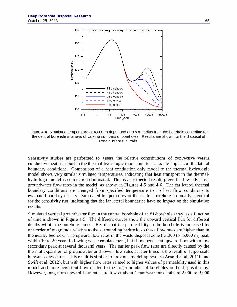
Deep Borehole Disposal Research October 25, 2013 65
Figure 4-4. Simulated temperature at 4,000 m depth and at 0.8 m radius from the borehole centerline for the central borehole in arrays of varying numbers of boreholes. Results are shown for the disposal of
used nuclear fuel rods.
Sensitivity studies are performed to assess the relative contributions of convective versus
conductive heat transport in the thermal-hydrologic model and to assess the impacts of the lateral
boundary conditions. Comparison of a heat conduction-only model to the thermal-hydrologic
model shows very similar simulated temperatures, indicating that heat transport in the thermal-
hydrologic model is conduction dominated. This is an expected result, given the low advective
groundwater flow rates in the model, as shown in Figures 4-5 and 4-6. The far lateral thermal
boundary conditions are changed from specified temperature to no heat flow conditions to
evaluate boundary effects. Simulated temperatures in the central borehole are nearly identical
for the sensitivity run, indicating that the far lateral boundaries have no impact on the simulation
results.
Simulated vertical groundwater flux in the central borehole of an 81-borehole array, as a function
of time is shown in Figure 4-5. The different curves show the upward vertical flux for different
depths within the borehole nodes. Recall that the permeability in the borehole is increased by
one order of magnitude relative to the surrounding bedrock, so these flow rates are higher than in
the nearby bedrock. The upward flow rates in the waste disposal zone (-3,000 to -5,000 m) peak
within 10 to 20 years following waste emplacement, but show persistent upward flow with a low
secondary peak at several thousand years. The earlier peak flow rates are directly caused by the
thermal expansion of groundwater and lower flow rates at later times is the result of large-scale
buoyant convection. This result is similar to previous modeling results (Arnold et al. 2011b and
Swift et al. 2012), but with higher flow rates related to higher values of permeability used in this
model and more persistent flow related to the larger number of boreholes in the disposal array.
However, long-term upward flow rates are low at about 1 mm/year for depths of 2,000 to 3,000
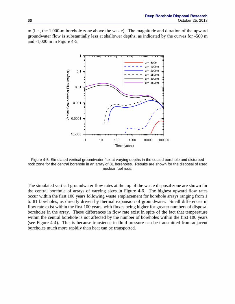
Deep Borehole Disposal Research
66 October 25, 2013
m (i.e., the 1,000-m borehole zone above the waste). The magnitude and duration of the upward
groundwater flow is substantially less at shallower depths, as indicated by the curves for -500 m
and -1,000 m in Figure 4-5.
Figure 4-5. Simulated vertical groundwater flux at varying depths in the sealed borehole and disturbed rock zone for the central borehole in an array of 81 boreholes. Results are shown for the disposal of used
nuclear fuel rods.
The simulated vertical groundwater flow rates at the top of the waste disposal zone are shown for
the central borehole of arrays of varying sizes in Figure 4-6. The highest upward flow rates
occur within the first 100 years following waste emplacement for borehole arrays ranging from 1
to 81 boreholes, as directly driven by thermal expansion of groundwater. Small differences in
flow rate exist within the first 100 years, with fluxes being higher for greater numbers of disposal
boreholes in the array. These differences in flow rate exist in spite of the fact that temperature
within the central borehole is not affected by the number of boreholes within the first 100 years
(see Figure 4-4). This is because transience in fluid pressure can be transmitted from adjacent
boreholes much more rapidly than heat can be transported.
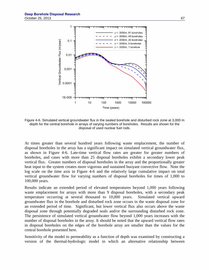
Deep Borehole Disposal Research October 25, 2013 67
Figure 4-6. Simulated vertical groundwater flux in the sealed borehole and disturbed rock zone at 3,000 m depth for the central borehole in arrays of varying numbers of boreholes. Results are shown for the
disposal of used nuclear fuel rods.
At times greater than several hundred years following waste emplacement, the number of
disposal boreholes in the array has a significant impact on simulated vertical groundwater flux,
as shown in Figure 4-6. Late-time vertical flow rates are greater for greater numbers of
boreholes, and cases with more than 25 disposal boreholes exhibit a secondary lower peak
vertical flux. Greater numbers of disposal boreholes in the array and the proportionally greater
heat input to the system creates more vigorous and sustained buoyant convective flow. Note the
log scale on the time axis in Figure 4-6 and the relatively large cumulative impact on total
vertical groundwater flow for varying numbers of disposal boreholes for times of 1,000 to
100,000 years.
Results indicate an extended period of elevated temperatures beyond 1,000 years following
waste emplacement for arrays with more than 9 disposal boreholes, with a secondary peak
temperature occurring at several thousand to 10,000 years. Simulated vertical upward
groundwater flux in the borehole and disturbed rock zone occurs in the waste disposal zone for
an extended period of time. Significant, but lower vertical flux also occurs above the waste
disposal zone through potentially degraded seals and/or the surrounding disturbed rock zone.
The persistence of simulated vertical groundwater flow beyond 1,000 years increases with the
number of disposal boreholes in the array. It should be noted that the upward vertical flow rates
in disposal boreholes on the edges of the borehole array are smaller than the values for the
central borehole presented here.
Sensitivity of the model to permeability as a function of depth was examined by constructing a
version of the thermal-hydrologic model in which an alternative relationship between
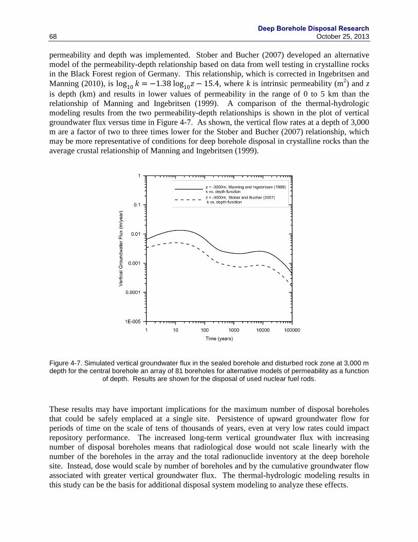
Deep Borehole Disposal Research
68 October 25, 2013
permeability and depth was implemented. Stober and Bucher (2007) developed an alternative
model of the permeability-depth relationship based on data from well testing in crystalline rocks
in the Black Forest region of Germany. This relationship, which is corrected in Ingebritsen and
Manning (2010), is , where k is intrinsic permeability (m2) and z
is depth (km) and results in lower values of permeability in the range of 0 to 5 km than the
relationship of Manning and Ingebritsen (1999). A comparison of the thermal-hydrologic
modeling results from the two permeability-depth relationships is shown in the plot of vertical
groundwater flux versus time in Figure 4-7. As shown, the vertical flow rates at a depth of 3,000
m are a factor of two to three times lower for the Stober and Bucher (2007) relationship, which
may be more representative of conditions for deep borehole disposal in crystalline rocks than the
average crustal relationship of Manning and Ingebritsen (1999).
Figure 4-7. Simulated vertical groundwater flux in the sealed borehole and disturbed rock zone at 3,000 m depth for the central borehole an array of 81 boreholes for alternative models of permeability as a function
of depth. Results are shown for the disposal of used nuclear fuel rods.
These results may have important implications for the maximum number of disposal boreholes
that could be safely emplaced at a single site. Persistence of upward groundwater flow for
periods of time on the scale of tens of thousands of years, even at very low rates could impact
repository performance. The increased long-term vertical groundwater flux with increasing
number of disposal boreholes means that radiological dose would not scale linearly with the
number of the boreholes in the array and the total radionuclide inventory at the deep borehole
site. Instead, dose would scale by number of boreholes and by the cumulative groundwater flow
associated with greater vertical groundwater flux. The thermal-hydrologic modeling results in
this study can be the basis for additional disposal system modeling to analyze these effects.
Deep Borehole Disposal Research October 25, 2013 69
4.2.2 Borehole-Scale Thermal-Hydrologic Effects
Borehole-scale thermal-hydrologic effects interact with the site-scale thermal-hydrology
discussed above, but are more specific to the borehole design, engineering and operational
practice. Borehole-scale effects focus on the regions between the emplaced waste, including the
waste package, the borehole liner (if any), the borehole wall, and the region of rock near the
borehole potentially altered by drilling and emplacement operations, grouting, and the post-
emplacement thermal transient from the waste decay heat (i.e., the EBS, DRZ, and surrounding
thermally impacted host rock).
An example issue is to understand the conditions that could enable significant vertical migration
of radionuclides. Such conditions may include vertical crevices or gaps between the waste and
the host rock that provide a vertical flow pathway, and the potential for inflow of water from the
nearby host rock that could feed vertical flow driven either by thermal buoyancy or thermal
expansion of crevice/gap water. As example would be lamellar corrosion of the waste package
wall or a liner (if present) that creates crevices oriented along the borehole axis. Other examples
could include incomplete grouting between the waste package and borehole wall or spallation of
the borehole wall. The potential for such small-scale crevice transport can be addressed through
a combination of modeling, laboratory testing, material selection and field test verification.
Questions include how the engineered materials or thermal effects may (1) create preferential
flow pathways within the DRZ and disposal boreholes and (2) augment thermal-hydrologic (TH)
flow and radionuclide migration within those pathways, as well as within the intact rock.
Representing the engineered system in its disturbed state is important, including formation of
corrosion products, such as lamellar structures on waste packages. A high-fidelity ‘near-field
scale’ TH modeling approach is required to improve understanding of physical processes and
conditions most strongly affecting heat-augmented radionuclide migration. The large number of
parameters and conceptual-model issues to be addressed necessitates this approach being
computationally efficient. In addition to parameters considered in past TH model sensitivity
analyses, it is important to address those that characterize preferential pathways. These
parameters include the geometries (radial extent) of the DRZ, borehole and waste packages, and
those of other engineered materials in the borehole, as well as the range of possible effective
porosity and permeability anisotropy. Spatially, the grid should be refined enough to resolve TH
conditions within the DRZ, boreholes, and waste packages. The grid should account for the
telescoping borehole geometry, individual waste packages, wellbore casing and liners, grout, and
seals. Because of the importance of the thermal expansion of brine, variability in fluid and rock
compressibility should be addressed. Full coupling of the influence of salinity and temperature
on water density is needed, as is the ability to address water density profiles that do not
necessarily monotonically vary with depth.
In effect, understanding and avoiding the potential for borehole-scale effects assures that the
long-term isolation addressed by the site-scale modeling is not “short circuited” by small-scale
processes in or near the borehole. A reasonable approach is to represent TH processes using a 2-
D radially-symmetric (RZ) model geometry that can be “embedded” in the site-scale modeling,
rather than use a full 3-D model, such as the simulation methods used in Section 3.3.1 and Gibb
et al. (2008a). This dramatically reduces computational expense, while allowing for fine grid
resolution in the radial and vertical directions, within the borehole and the DRZ, which enables
Deep Borehole Disposal Research
70 October 25, 2013
representing waste packages of different heat output. To explore the boundaries of crevice
effects, this model should able to use grids in the sub-millimeter scale where needed. The model
would also be able to represent degraded or failed waste packages and their potential influence
on local transport processes. The model can also represent locally the details of the zones
between waste packages or strings of waste packages, as well as near seals and the interface with
the isolation zone above the uppermost packages. This efficiency makes it possible to address
computationally challenging physical interactions, such as the influence of temperature and
salinity on brine density. Such 2-D RZ models have been validated for regular well patterns
used in geologic CO2 sequestration and in geothermal systems. The borehole-scale model must
interface with the site-scale model discussed in the previous section. It can spatially resolve the
geometry of the engineered system, both in its original and disturbed states, and address
questions about the importance of respective EBS components to radionuclide isolation, which
will provide useful guidance in identifying and prioritizing laboratory- and field-scale testing
activities. This model can also address detailed thermal management questions, such as how
waste packages of differing heat output can be arranged to assure isolation performance.
It is expected that the primary information on borehole-scale effects and the evolution of
emplaces materials can be demonstrated in laboratory testing, with eventual field verification
focused on assuring the validity of the modeling assumption and testing conditions. Field-testing
will also demonstrate the reliability of operational processes for emplacing (and removing) the
engineered materials that dominate these borehole-scale performance issues.
4.2.3 Nuclear Criticality
Deployment of DBD will require assurance that nuclear criticality can be precluded at all times,
including surface operations as well as under long-term post-emplacement conditions when the
container and fuel become degraded. It has been proposed (Brady et al. 2009, Section 4.3) that
criticality may be excluded at the stage of FEPs screening for DBD. The demonstration project
RD&D program should include analysis to confirm such exclusion, along with definition of any
design, operation or site parameters that are needed to assure such exclusion.
Criticality safety is not a design, operation or permitting issue for conducting the demonstration
project, because the use of actual nuclear fuel is not anticipated. Thus, criticality safety during
RD&D is limited to conducting any analyses required to inform a transition from demonstration
to deployment, and to define any information needed from the demonstration testing.
Analysis will be performed during the RD&D program to provide a basis for criticality safety
assurance for DBD deployment. Because anticipated DBD waste canisters contain a single fuel
assembly, criticality safety assurance during normal handling operations and plausible abnormal
conditions can be demonstrated using standard analysis similar to those used for handling fresh
low enriched uranium (LEU) reactor fuel.
The primary criticality concern for DBD is to preclude any plausible scenarios for criticality in
the long-term post-emplacement period. A single fuel assembly remains subcritical even when
flooded with moderating water. Thus, any potential criticality scenario would require re-
distribution of fissile material within a container, and potentially between multiple containers in
an emplacement string. If criticality exclusion relies on one or more DBD design or site feature,
then those features should be demonstrated in either laboratory or field testing or demonstration.

Deep Borehole Disposal Research October 25, 2013 71
These features could include a container design that limits achievable uranium-water
concentrations or restricts material re-distribution, or a groundwater composition that limits
criticality (either natural or as modified by the borehole and contents).
Analysis during the DBD demonstration project will define the parameter space of possible
criticality, and identify design and site features that can assure that DBD operates beyond any
plausible criticality scenario. Most or all of the information needed will be obtained by lab and
field testing. Any additional design, operational, or site characteristic data needs that are
identified specifically for criticality control will be added to the demonstration and testing
program.
4.2.4 Operational Safety Assessment
Operational safety for DBD operations can be divided into two categories. First is the
conventional industrial safety for site operations, primarily the drilling operations and the
handling of drilling materials. Second is the nuclear operation safety of handling and emplacing
highly radioactive used nuclear fuel or high-level radioactive waste.
The conventional industrial safety requirements for a field demonstration will be very similar to
the conventional operational safety requirements for actual disposal operations. The drilling and
material handling for a full-scale field demonstration borehole is comparable to an operating
disposal borehole. These conventional operations will be subject to existing drilling safety
institutional controls: laws, regulations, standards and practices – at Federal, state and local
levels. Other than demonstrating compliance with these controls and demonstrating safe
operations at the field demonstration, there are little or no additional data needs for this aspect of
operational safety.
The nuclear operational safety issue is similar to the criticality issue discussed above. As there
will not be radioactive material emplaced in the field demonstration, there will not be actual
nuclear operational safety issues. However, the demonstration should begin to address the
questions of how nuclear operations would be conducted in an actual disposal operation, where
the nuclear safety issues are significant. In current design concepts, the waste packages are not
self-shielded, and thus have very high external radiation levels. This requires the waste package
handling equipment and the emplacement operating area to have heavy shielding, and forces
remote operation at the borehole surface facility. Contrary to common drilling practice, the
emplacement string of waste packages will have to be remote assembled and the wellhead
operations would be “hands-off”. A significant challenge will be to assure that the range of
potential ‘off-normal’ operating conditions can be managed without having to expose workers to
the emplacement string, as even short exposures are not likely to be acceptable. In common
industrial practice, even where routine operations have become highly automated, hands-on
troubleshooting for off-normal conditions is typically assumed, and this will not be possible
where an exposed waste package is present. Placing as much equipment as possible in shielded
areas, as well as mobile temporary shielding for specific operating conditions, may be required in
the DBD design.
The field demonstration does not need any shielding, but could endeavor to incorporate and
demonstrate aspects of remote handling and emplacement. It is not necessary for all of the
demonstration operations to be conducted in this manner, just a demonstration that remote
Deep Borehole Disposal Research
72 October 25, 2013
handling is conceptually possible. This capability will add cost to the demonstration facility,
implying that the extent of remote operation used in the demonstration project will be part of the
cost-benefit trade-off to be determined during detailed planning for the field demonstration. It is
also likely that some (or even all) of this remote handling can be demonstrated in a “near-
surface” industrial facility that could be less expensive than demonstration at the DBD field test
itself. The information obtained from such field or industrial-site demonstrations will be useful
in DBD design and planning, and it is possible that the need for high-confidence remote
operations will constrain the design of the waste packages and the ‘concept of operations’ for an
operating DBD site.
4.3 Analysis of Performance Assessment Results
A systematic approach to identify and prioritize science and engineering needs during the
demonstration phase of the DBD concept was described in the Research, Development, and
Demonstration Roadmap for Deep Borehole Disposal (DOE 2012a). This section presents a
synthesis of previous PA studies that supports the importance metric in the prioritization
methodology. These analyses have been limited to undisturbed (in the absence of external
events) post-closure performance.
4.3.1 Deep Borehole Disposal of High-Level Radioactive Waste Study
A preliminary safety assessment using an analytical solution of the advection-diffusion equation
was conducted in Brady et al. (2009) conditioned on thermal-hydrologic calculations, which
indicated that vertical transport was limited to a short thermal period. These DB-PA results are
based on several bounding and conservative assumptions, such as: (1) all waste is assumed to
instantly degrade and dissolve inside the waste canisters; (2) all waste is assumed to be PWR
assemblies; and (3) no credit is taken for sorption or decay along the saturated zone transport
pathway from the sealed borehole to the withdrawal well calculated to take 8,000 years.
Sealed borehole properties representative of bentonite in conjunction with the thermally driven
driving pressure produced an upward fluid pore velocity of 0.502 m/yr and a corresponding
1000 m borehole travel time of 1990 years for an unretarded radionuclide.
Radionuclide transport up the borehole from the source (waste disposal zone) occurred for
approximately 200 years, corresponding to the duration of the thermally driven flow.
Subsequent to the thermal period, ambient conditions were not expected to provide any upward
gradient, and upward radionuclide transport was assumed to cease. The only radionuclide with a
non-zero concentration 1000 m above the waste disposal zone in the sealed borehole was 129
I,
which is the only radionuclide that had no retardation in the analysis. The non-zero 129
I
concentration (5.3108
mg/L) represented the leading edge of the dispersive transport front.
However, the center of mass never reaches the top of the 1000 m sealed section of the borehole
because there was no further movement after 200 years. The total dose to the reasonably
maximally exposed individual (RMEI) at 8,200 years was 1.41010
mrem/yr.
Some high-level conclusions from Brady et al. (2009), relevant to the deep borehole
demonstration activities are:
Deep Borehole Disposal Research October 25, 2013 73
1) The coupled thermal-hydrologic-chemical-mechanical behavior of the borehole and
disturbed region during the thermal pulse, and in the presence of density-stratified waters,
should be modeled more accurately.
a. High PA metric rating for Science Activities: Temperature Log, Waste Canister
Mockup Electrical Heater Test, Fluid Samples from Packer Testing, Drill
Cuttings, Intermittent Coring, Chemical Equilibrium Modeling, TH Modeling,
Conceptual Model Design, Numerical Model Implementation of Sub-Models,
Construction of System Model.
b. Moderate PA metric rating for Science Activities: Chemical Kinetics Modeling
2) Additional consideration should be focused on the design and long-term performance of
deep seals.
a. High PA metric rating for Science Activities: Fluid Samples from Packer Testing,
Seals Integrity Testing and Cement Degradation Testing and Engineering
Activities: Demonstration of Casing Emplacement, Demonstration of Liner
Emplacement, Bentonite Seal Emplacement, Cement Seal Emplacement.
3) Modeling of the full-system performance of multi-borehole arrays should be undertaken,
consistent with an assumption that a regional borehole disposal facility could entail an
array of 10 to 100 individual boreholes.
a. Moderate PA metric rating for Science Activities: Multi-Well Hydraulic Testing,
Cross-Hole Tomography, Multi-Borehole Modeling.
4.3.2 Deep Borehole Seals Study
A preliminary performance assessment model for the deep borehole disposal system was used to
analyze the relationship between the effectiveness of the borehole seals and risk to human health
using Monte Carlo sampling for propagating uncertainty (Herrick et al., 2011). The objective of
this analysis was to determine the maximum effective permeability of the borehole seals and the
surrounding DRZ that would result in an acceptable level of risk, as estimated by radiological
dose.
In the disposal system model, the waste-disposal zone contained 400 waste canisters in the lower
2,000 m of the 5,000 m long borehole. The upper 3000 m consisted of a 1000 m seal zone of
bentonite directly above the waste zone and a 2000-m upper zone extending to the surface
consisting of backfill. Waste canisters were surrounded by bentonite grout and strings of
canisters were separated by bridge plugs and compressed bentonite plugs. Flow and radionuclide
transport occurred in the waste-disposal and seal zones with an effective 1 m2 cross-section that
included the borehole, canisters, grout, seals, and the surrounding DRZ. Twenty FEHM
simulation runs were carried out with different rock and disturbed zone permeability values for
the SNF assembly waste.
Results from a detailed the thermal-hydrologic model were coupled to the generic deep borehole
disposal system model. The thermal hydrologic simulations assumed 9 boreholes with borehole
spacing of 200 m. For the sensitivity study, 20 different host rock and effective seal/disturbed
rock zone permeability combinations were investigated. Thermal-hydrologic simulations were
conducted for three major types of waste, as summarized below.
Deep Borehole Disposal Research
74 October 25, 2013
Commercial Spent Nuclear Fuel (CSNF): Flow at the top of the waste disposal zone generally
decreases throughout time. Some permeability combinations decrease continuously, while others
have a peak around 10 years and then decrease continuously. The only exceptions to these
trends are those cases with a host rock permeability of 1019
m2. In each of these exceptions,
upward flow decreases continuously and turns downward between 2,000 and 10,000 years after
which upward flow resumes at a lower velocity and then decreases continuously to 1,000,000
years. Initial upward flow varies between 104
m/yr and 10 m/yr and either turns downward or
declines approximately 4 orders of magnitude by 1,000,000 years. Each order of magnitude
decrease in permeability of the intact rock or DRZ results in approximately an order of
magnitude drop in upward velocity.
The temperature profiles at the top of the disposal zone associated with all of the 20 permeability
combinations are nearly identical beginning at an ambient temperature of 85°C and peaking
about 50°C higher and then declining asymptotically back to ambient after about 100,000 years.
The similarity in temperature profiles for all permeability combinations indicates that the heat
flow is conduction dominated. This may be due to the fact that convection occurs mainly around
the narrow borehole and excavated rock zone region, while conduction could occur in the larger
intact rock. Additionally, temperature and vertical groundwater flux in the host rock decreases
rapidly with increasing horizontal distance from the borehole. Vertical groundwater flow rates in
the borehole also decrease rapidly with vertical distance above the waste disposal zone.
High Level Waste: Simulations were also carried out for DOE defense HLW. For this waste
type simulations were conducted for the base case and upper bounding permeability values only.
Compared to CSNF, upward vertical flow rates at the top of the disposal zone for HLW are about
two orders of magnitude lower, and significant vertical upwards flows do not extend beyond
several hundred years. This can be attributed to the lower heat output of the HLW, as evidenced
by the lower temperature rise only a few degrees higher than the initial condition, in contrast to
the 50 °C rise for the SNF assembly waste.
Reprocessed Waste: Simulations were also carried out for reprocessed waste (RW). The
groundwater fluxes for the reprocessed waste are slightly higher than those for the SNF assembly
waste. The peak temperature is about 90 °C higher than the initial condition. As with CSNF and
HLW, the reprocessed waste shows little temperature changes as a result of permeability
changes.
Table 4-2 summarizes the results from the six cases reported, which considered two inventory
cases: CSNF and DOE HLW and two disposal system cases: a Base Case and a Seal Degraded
Case, and cases with or without the sorption of iodine.

Deep Borehole Disposal Research October 25, 2013 75
Table 4-2. Summary of Results from Herrick et al. (2011)
Case Iodine Sorption
Waste Type
Peak Dose Rate: mrem/yr
Time of Peak: yr
Notes
Base No CSNF 10-14
1,000,000
Base Yes CSNF No release NA
Base Yes HLW No release NA
Degraded No CSNF 310-2
10,000
Degraded Yes CSNF 210-3
1,000,000 36
Cl dominates between 1,000 and 100,000 yrs.
99Tc, and
79Se also contribute.
Degraded Yes HLW 310-8
1,000,000
Some high-level conclusions from Herrick et al. (2011) relevant to the deep borehole
demonstration activities are:
1) Heat load is a driver for upward flow of fluids and thermal conduction into surrounding
host rock greatly dominates heat transfer mechanisms.
a. High PA metric rating for Science activities: Source Term Modeling, TH
Modeling, Construction of System Model, Waste Canister Mockup Electrical
Heater Test, Temperature Log, Drill Cuttings, Intermittent Coring
2) Upward flow rapidly diminishes with distance above the disposal zone
a. High PA metric rating for Science activity: TH Modeling
3) Seal permeabilites on the order of 1016
m2 are sufficient to limit releases and seal
integrity is a dominant driver for releases to the biosphere.
a. High PA metric rating for Science activities: Fluid Samples from Packer Testing,
Seal Integrity Testing, Cement Degradation Testing and Engineering Activities:
Demonstration of Casing Emplacement, Demonstration of Liner Emplacement,
Bentonite Seal Emplacement, Cement Seal Emplacement
4) 129I dominates radioactive releases and sorption of
129I greatly reduces or eliminates
release.
a. High PA metric rating for Science activities: Source Term Modeling, Chemical
Equilibrium Modeling, Fluid Samples from Packer Testing, Radionuclide
Characterization, Seal Zone Sorbent Testing
4.3.3 Generic Disposal System Modeling Fiscal Year 2011 Progress Report
A preliminary safety assessment and some supporting system and sub-system sensitivity
analyses of deep borehole disposal were conducted by Clayton et al. (2011). In these analyses,
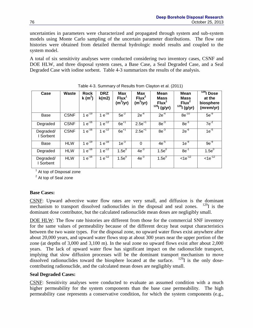
Deep Borehole Disposal Research
76 October 25, 2013
uncertainties in parameters were characterized and propagated through system and sub-system
models using Monte Carlo sampling of the uncertain parameter distributions. The flow rate
histories were obtained from detailed thermal hydrologic model results and coupled to the
system model.
A total of six sensitivity analyses were conducted considering two inventory cases, CSNF and
DOE HLW, and three disposal system cases, a Base Case, a Seal Degraded Case, and a Seal
Degraded Case with iodine sorbent. Table 4-3 summarizes the results of the analysis.
Table 4-3. Summary of Results from Clayton et al. (2011)
Case Waste Rock k (m
2)
DRZ k(m2)
Max Flux
1
(m3/yr)
Max Flux
2
(m3/yr)
Mean Mass Flux
1
129I (g/yr)
Mean Mass Flux
2
129I (g/yr)
129I Dose
at the biosphere (mrem/yr)
Base CSNF 1 e-19
1 e-16
5e-2
2e-4
2e-4
8e-10
5e-9
Degraded CSNF 1 e-16
1 e-12
6e+1
2.5e+1
8e-3
8e-3
7e-2
Degraded/ I Sorbent
CSNF 1 e-16
1 e-12
6e+1
2.5e+1
8e-3
2e-6
1e-5
Base HLW 1 e-19
1 e-16
1e-3
0 4e-5
1e-9
9e-9
Degraded HLW 1 e-16
1 e-12
1.5e0 4e
-3 1.5e
0 8e
-1 1.5e
0
Degraded/ I Sorbent
HLW 1 e-16
1 e-12
1.5e0 4e
-3 1.5e
0 <1e
-12 <1e
-12
1 At top of Disposal zone
2 At top of Seal zone
Base Cases:
CSNF: Upward advective water flow rates are very small, and diffusion is the dominant
mechanism to transport dissolved radionuclides in the disposal and seal zones. 129
I is the
dominant dose contributor, but the calculated radionuclide mean doses are negligibly small.
DOE HLW: The flow rate histories are different from those for the commercial SNF inventory
for the same values of permeability because of the different decay heat output characteristics
between the two waste types. For the disposal zone, no upward water flows exist anywhere after
about 20,000 years, and upward water flows stop at about 300 years near the upper portion of the
zone (at depths of 3,000 and 3,100 m). In the seal zone no upward flows exist after about 2,000
years. The lack of upward water flow has significant impact on the radionuclide transport,
implying that slow diffusion processes will be the dominant transport mechanism to move
dissolved radionuclides toward the biosphere located at the surface. 129
I is the only dose-
contributing radionuclide, and the calculated mean doses are negligibly small.
Seal Degraded Cases:
CSNF: Sensitivity analyses were conducted to evaluate an assumed condition with a much
higher permeability for the system components than the base case permeability. The high
permeability case represents a conservative condition, for which the system components (e.g.,

Deep Borehole Disposal Research October 25, 2013 77
host rock, disturbed rock zone, seals, etc.) have grossly failed, resulting in a much higher
permeability than the expected design permeability values.
Water flows upward at considerably higher rates than the base permeability case for both zones
over the entire simulation time. At the top of the disposal zone the mean advective release rates
are much higher than the mean diffusive release rates for the entire simulation time. Other
radionuclides such as 237
Np, 107
Pd and 93
Nb have higher mean release rates than 129
I. 237
Np and 135
Cs are two dominant radionuclides in terms of the diffusive release rate.
At the top of the seal zone 129
I has the highest mean release rate by both diffusion and advection,
and the mean advective release rate is much higher than the mean diffusive release rate. Sorbing
radionuclides are effectively retarded during transport in the seal zone. Compared to the base
permeability case, many other radionuclides (notably 99
Tc, 36
Cl, 79
Se, etc.) are released at
considerably high rates.
The mean dose in the biosphere is dominated by 129
I, with contributions from 99
Tc and 36
Cl.
DOE HLW: The upward flow rates are generally lower than the commercial SNF inventory case
because of the lower heat loading. Some sections of the disposal zone (at depths between 3,500
and 3,300 m) have no upward flow after about 5,000 to 12,000 years. As in the commercial SNF
inventory case, advection dominants transport.
At the top of the disposal zone, 129
I dominates release prior to 5,000 years, after which the
release from 79
Se, 135
Cs are comparable and 93
Nb is an additional important contributor. At the
top of the seal zone 129
I and 99
Tc are the only radionuclides that are released, mainly because of
sorption on the bentonite seal material. It is interesting to note that the 129
I peak mean mass
release rate is higher than that of the commercial SNF inventory case. This is a result of the
higher degradation rate of the borosilicate glass waste form the DOE HLW, which releases 129
I
from the waste form at a faster rate. Both waste types have a comparable 129
I inventory. The 129
I
mean mass release rate reaches a peak at about 12,000 years and then decreases by about two
orders of magnitude before it levels off.
The magnitude of the 129
I peak mean dose is higher than that of the commercial SNF inventory
case, reaching about 2 mrem/yr at 12,000 years.
Degraded Seal Case with Iodine Sorbent:
All analyses to date show that 129
I is the dominant dose contributor for releases from a deep
borehole disposal system. This is an expected outcome considering the key characteristics of 129
I
relevant to geologic disposal of radioactive waste: unlimited solubility, no sorption or very weak
sorption on typical geologic material, and extremely long half-life (about 17 million years). One
approach to mitigate the potential release of 129
I is to load the seal materials with an effective
sorbent for iodine.
Sensitivity analyses were conducted to evaluate potential impacts of iodine sorbent (getter) in the
seal zone on the generic disposal system performance. The sensitive analyses were performed
for the degraded seal case.
CSNF: The mean mass release rates at the top of the seal zone are no longer dominated by 129
I. 99
Tc and 36
Cl have higher mean mass release rates than 129
I. The peak mean dose in the
biosphere is dominated mostly by 99
Tc and 36
Cl. The total peak mean dose is reduced by about
two orders of magnitude from the case where there is no sorption of iodine.

Deep Borehole Disposal Research
78 October 25, 2013
DOE HLW: The 129
I mean release rate from the seal zone is completely suppressed. 99
Tc is the
only radionuclide that is released at a noticeable mean rate, and is the single dose contributor at
the hypothetical AE. The total peak mean dose is reduced by about six orders of magnitude from
the non-sorption case.
Conclusions learned from the Clayton et al. (2011) analyses relevant to prioritization of deep
borehole demonstration activities are:
1) Diffusion dominates transports in the base case while advection dominates when seals
performance degrades.
a. High PA metric rating for Science activities: Drill Cuttings, Intermittent Coring
2) Proper emplacement of seal components and their long term behavior are important even
under failed seal conditions; potential doses are well below current regulatory standards.
a. High PA metric rating for Science activities: Fluid Samples from Packer Testing,
Seal Integrity Testing, Cement Degradation Testing and Engineering Activities:
Demonstration of Casing Emplacement, Demonstration of Liner Emplacement,
Bentonite Seal Emplacement, Cement Seal Emplacement
3) The use of iodine sorbent in the seal zone is quite effective at reducing dose.
a. High PA metric rating for Science activities: Source Term Modeling, Chemical
Equilibrium Modeling, Fluid Samples from Packer Testing, Radionuclide
Characterization, Seal Zone Sorbent Testing
4) Eliminating or reducing causes of upward flow is important in the event of seal failure.
a. High PA metric rating for Science activities: Fluid Samples from Packer Testing,
Seal Integrity Testing, Cement Degradation Testing and Engineering Activities:
Demonstration of Casing Emplacement, Demonstration of Liner Emplacement,
Bentonite Seal Emplacement, Cement Seal Emplacement, Source Term
Modeling, TH Modeling, Construction of System Model, Waste Canister Mockup
Electrical Heater Test, Temperature Log, Drill Cuttings, Intermittent Coring.
4.3.4 Generic Deep Geologic Disposal Safety Case (Freeze et al. 2013)
A preliminary safety assessment and some supporting system and sub-system sensitivity
analyses of deep borehole disposal were conducted in Freeze et al. (2013). In these analyses, a
set of “one-off,” ceirtus paribus, simulations were performed where individual parameter values
were varied while holding all other parameters at baseline values.
The effect of waste form degradation rates, sorption of 129
I in the waste disposal region, sorption
of 129
I in the seal zone, and molecular diffusion were evaluated. Table 4-4 presents the 13 cases
that were evaluated. Table 4-5 presents a summary of the results.
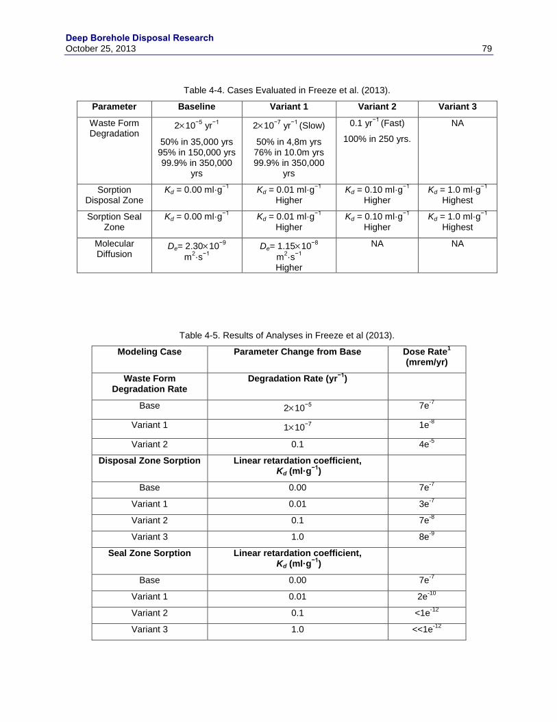
Deep Borehole Disposal Research October 25, 2013 79
Table 4-4. Cases Evaluated in Freeze et al. (2013).
Parameter Baseline Variant 1 Variant 2 Variant 3
Waste Form Degradation
210−5
yr−1
50% in 35,000 yrs 95% in 150,000 yrs 99.9% in 350,000
yrs
210−7
yr−1
(Slow)
50% in 4,8m yrs 76% in 10.0m yrs 99.9% in 350,000
yrs
0.1 yr−1
(Fast)
100% in 250 yrs.
NA
Sorption Disposal Zone
Kd = 0.00 ml·g−1
Kd = 0.01 ml·g−1
Higher Kd = 0.10 ml·g
−1
Higher Kd = 1.0 ml·g
−1
Highest
Sorption Seal Zone
Kd = 0.00 ml·g−1
Kd = 0.01 ml·g−1
Higher Kd = 0.10 ml·g
−1
Higher Kd = 1.0 ml·g
−1
Highest
Molecular Diffusion
De= 2.3010−9
m2·s
−1
De= 1.1510−8
m2·s
−1
Higher
NA NA
Table 4-5. Results of Analyses in Freeze et al (2013).
Modeling Case Parameter Change from Base Dose Rate1
(mrem/yr)
Waste Form Degradation Rate
Degradation Rate (yr−1
)
Base 210−5
7e-7
Variant 1 110−7
1e-8
Variant 2 0.1 4e-5
Disposal Zone Sorption Linear retardation coefficient, Kd (ml·g
−1)
Base 0.00 7e-7
Variant 1 0.01 3e-7
Variant 2 0.1 7e-8
Variant 3 1.0 8e-9
Seal Zone Sorption Linear retardation coefficient, Kd (ml·g
−1)
Base 0.00 7e-7
Variant 1 0.01 2e-10
Variant 2 0.1 <1e-12
Variant 3 1.0 <<1e-12
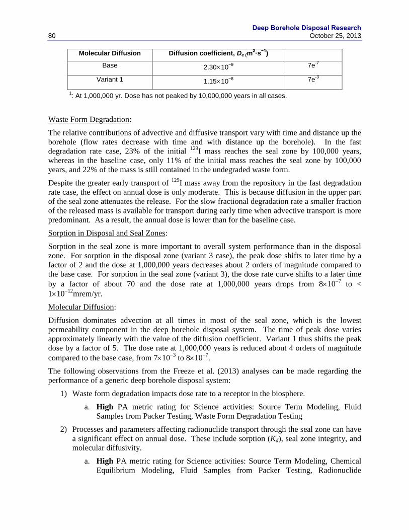
Deep Borehole Disposal Research
80 October 25, 2013
Molecular Diffusion Diffusion coefficient, De (m2·s
−1)
Base 2.3010−9
7e-7
Variant 1 1.1510−8
7e-3
1: At 1,000,000 yr. Dose has not peaked by 10,000,000 years in all cases.
Waste Form Degradation:
The relative contributions of advective and diffusive transport vary with time and distance up the
borehole (flow rates decrease with time and with distance up the borehole). In the fast
degradation rate case, 23% of the initial 129
I mass reaches the seal zone by 100,000 years,
whereas in the baseline case, only 11% of the initial mass reaches the seal zone by 100,000
years, and 22% of the mass is still contained in the undegraded waste form.
Despite the greater early transport of 129
I mass away from the repository in the fast degradation
rate case, the effect on annual dose is only moderate. This is because diffusion in the upper part
of the seal zone attenuates the release. For the slow fractional degradation rate a smaller fraction
of the released mass is available for transport during early time when advective transport is more
predominant. As a result, the annual dose is lower than for the baseline case.
Sorption in Disposal and Seal Zones:
Sorption in the seal zone is more important to overall system performance than in the disposal
zone. For sorption in the disposal zone (variant 3 case), the peak dose shifts to later time by a
factor of 2 and the dose at 1,000,000 years decreases about 2 orders of magnitude compared to
the base case. For sorption in the seal zone (variant 3), the dose rate curve shifts to a later time
by a factor of about 70 and the dose rate at 1,000,000 years drops from 8107
to <
11012
mrem/yr.
Molecular Diffusion:
Diffusion dominates advection at all times in most of the seal zone, which is the lowest
permeability component in the deep borehole disposal system. The time of peak dose varies
approximately linearly with the value of the diffusion coefficient. Variant 1 thus shifts the peak
dose by a factor of 5. The dose rate at 1,000,000 years is reduced about 4 orders of magnitude
compared to the base case, from 7103
to 8107
.
The following observations from the Freeze et al. (2013) analyses can be made regarding the
performance of a generic deep borehole disposal system:
1) Waste form degradation impacts dose rate to a receptor in the biosphere.
a. High PA metric rating for Science activities: Source Term Modeling, Fluid
Samples from Packer Testing, Waste Form Degradation Testing
2) Processes and parameters affecting radionuclide transport through the seal zone can have
a significant effect on annual dose. These include sorption (Kd), seal zone integrity, and
molecular diffusivity.
a. High PA metric rating for Science activities: Source Term Modeling, Chemical
Equilibrium Modeling, Fluid Samples from Packer Testing, Radionuclide
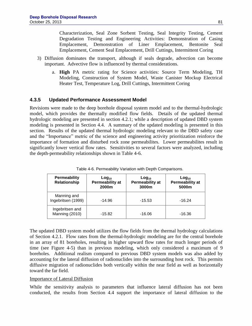
Deep Borehole Disposal Research October 25, 2013 81
Characterization, Seal Zone Sorbent Testing, Seal Integrity Testing, Cement
Degradation Testing and Engineering Activities: Demonstration of Casing
Emplacement, Demonstration of Liner Emplacement, Bentonite Seal
Emplacement, Cement Seal Emplacement, Drill Cuttings, Intermittent Coring
3) Diffusion dominates the transport, although if seals degrade, advection can become
important. Advective flow is influenced by thermal considerations.
a. High PA metric rating for Science activities: Source Term Modeling, TH
Modeling, Construction of System Model, Waste Canister Mockup Electrical
Heater Test, Temperature Log, Drill Cuttings, Intermittent Coring
4.3.5 Updated Performance Assessment Model
Revisions were made to the deep borehole disposal system model and to the thermal-hydrologic
model, which provides the thermally modified flow fields. Details of the updated thermal
hydrologic modeling are presented in section 4.2.1; while a description of updated DBD system
modeling is presented in Section 4.4. A summary of the updated modeling is presented in this
section. Results of the updated thermal hydrologic modeling relevant to the DBD safety case
and the “Importance” metric of the science and engineering activity prioritization reinforce the
importance of formation and disturbed rock zone permeabilites. Lower permeabilites result in
significantly lower vertical flow rates. Sensitivities to several factors were analyzed, including
the depth-permeability relationships shown in Table 4-6.
Table 4-6. Permeability Variation with Depth Comparisons.
Permeability Relationship
Log10 Permeability at
2000m
Log10 Permeability at
3000m
Log10 Permeability at
5000m
Manning and Ingebritsen (1999) -14.96 -15.53 -16.24
Ingebritsen and Manning (2010) -15.82 -16.06 -16.36
The updated DBD system model utilizes the flow fields from the thermal hydrology calculations
of Section 4.2.1. Flow rates from the thermal-hydrologic modeling are for the central borehole
in an array of 81 boreholes, resulting in higher upward flow rates for much longer periods of
time (see Figure 4-5) than in previous modeling, which only considered a maximum of 9
boreholes. Additional realism compared to previous DBD system models was also added by
accounting for the lateral diffusion of radionuclides into the surrounding host rock. This permits
diffusive migration of radionuclides both vertically within the near field as well as horizontally
toward the far field.
Importance of Lateral Diffusion
While the sensitivity analysis to parameters that influence lateral diffusion has not been
conducted, the results from Section 4.4 support the importance of lateral diffusion to the
Deep Borehole Disposal Research
82 October 25, 2013
performance of deep borehole disposal. In the presence of lateral diffusion radionuclides
become more dispersed and their concentrations are attenuated because of access to large
volumes of host rock, which surround the borehole and where many radionuclide species become
sorbed. In the disposal zone the lateral diffusive flux of radionuclides exceeds vertical advective
flux in the borehole. In the seal zone and upper zones the lateral diffusive flux is the same order
of magnitude as their vertical advective flux. Up to 100,000 years mean total release at the top
of the disposal zone is dominated by advection in the borehole region, after which vertical
diffusion in the surrounding host dominates. In the seal zone vertical diffusion in the host rock
dominates vertical borehole advection for all time. It should be noted that advection in the host
rock is not currently considered in these or earlier simulations. The relatively strong vertical
diffusion is a result of a relatively large vertical radionuclide concentration gradient that is
established in the host rock.
Updated Sensitivity Analyses
In Section 4.4, disposal system modeling results of sensitivities to the SNF waste form
degradation rate, vertical advective flux in the borehole, and to permeabilities are presented.
Sensitivity to SNF Degradation Rate
In the analysis described in Section 4.4.2.2 the degradation rate of the SNF waste form is
increased by a factor of 100. This results in an increase in the peak mean mass flux at the top of
the disposal zone from 2104
g/yr to 6103
g/yr ( a factor of 30) and at the top of the seal zone
from 21013
g/yr to 21011
g/yr ( a factor of 100).
Sensitivity to Borehole Flux
The vertical flux in the borehole was increased by a factor of 10 across all time and locations.
This could be a surrogate for the consequences of a poorly placed seal system (poor contact
between seal components and borehole wall) or deterioration of seal material or DRZ. This
order of magnitude increase in vertical flux up the borehole results in a modest increase in
release at the top of the disposal zone from 5104
g/yr to 2104
g/yr (a factor of 2.5). The
increase in release midway in the seal zone is from 5106
g/yr to 3107
g/yr; a factor of 17)
while the increase at the top of the seal zone is from 8109
g/yr to 21013
g/yr (a factor of
40,000), although the magnitude is quite small, regardless.
Past simulations that did not include lateral diffusion also examined the sensitivity to vertical
flux through large changes in seal permeability. While direct comparisons between previous
analyses and the analysis of Section 4.4 are limited because of differences in many of the process
representations and implementations, such comparisons are suggestive of the assertion that
accounting for lateral diffusion reduces the sensitivities of mass flux and dose to other processes.
For example, in Clayton et al. (2011) a degraded seal zone permeability case resulted in an
increase in the maximum vertical flux at the top of the disposal zone from 0.8 to 20 m/yr (a
factor of 25) and at the top of the seal zone from 103
to 0.2 m/yr (a factor of 200). This resulted
in corresponding increase in mean mass flux of 129
I (the dominant radionuclide released) from
2104
g/yr to 3102
g/yr (a factor of 150) at the top of the disposal zone and from 8108
g/yr
to 8103
g/yr ( a factor of 107) at the top of the seal zone. In Herrick et al. (2011), the same
changes in maximum vertical borehole flux translated to an increase in the dose rate to the
biosphere from 11014
g/yr to 6102
g/yr (a factor of 1010
). The magnitude of these changes,
Deep Borehole Disposal Research October 25, 2013 83
which do not include the effect of lateral diffusion, is much greater than in the updated disposal
system model, described in Section 4.4.
Sensitivity to Permeability
The values of permeability at various depths for the base case (Manning and Ingebritsen, 1999)
and the alternate case (Ingebritsen and Manning, 2010) are shown in Table 4-6). Comparison of
these cases show very limited differences in mean total mass flux at the top of the disposal zone
and seal zone, respectively. This is because of the differences in permeability (see Table 4-6)
and because of the lateral diffusion, which attenuates vertical release reduces the importance of
uncertainty in other processes.
Conclusions
Some high-level conclusions from the updated thermal hydrology and DBD system modeling
relevant to the prioritization of science and engineering activities are:
1. Science and engineering activities that support the determination of diffusive properties
in the host rock are very important and ranked high.
2. Science and engineering activities, that help quantify the magnitude of vertical flow up
the borehole are very important and ranked high.
3. Science and engineering activities that support the determination of SNF degradation are
somewhat important and ranked moderate.
4. Because of the limited differences in the host rock and DRZ permeabilities used in this
analysis, it is difficult to draw many conclusions with respect to the importance of these
parameters on deep borehole disposal performance. Earlier analyses indicated these
parameters are very important. Additional sensitivity analyses that include lateral
diffusion are required to examine whether accounting for lateral diffusion reduces the
overall sensitivity of host rock and DRZ permeability to disposal system performance.
4.3.6 Demonstration of Deep Borehole Disposal Post-Closure Safety
The analyses conducted to date not only identify deep borehole disposal system sensitivities but
also demonstrate disposal safety, with the caveat that the assessments conducted to date are
preliminary, simplified and require additional pedigree. Table 4-7 presents the baseline dose
rates from the assessments.
Table 4-7. Summary of Performance Assessment Results.
Assessment Peak Dose Rate
(mrem/yr)
Time of Peak (yr)
Dominate Radionuclides
Note
Brady et al (2009) 1.4e10 8,200 129
I, only Assumed 8,000 travel time to the biosphere, instant release, no sorption in natural system
Herrick et al. (2011) <1e14 1,000,000 129
I, only
Clayton et al. (2011) 5e9 1,000,000 129
I and 36Cl, only
Deep Borehole Disposal Research
84 October 25, 2013
Freeze et al. (2013) 7e7 1,000,000 Only considered 129
I
This report, Section 4.4
0. N/A NA
The results of all preliminary system analyses confirm that the deep borehole disposal system is
very effective in containing and confining nuclear wastes, with predicted peak dose rates
between zero to 7107
mrem/yr under undisturbed conditions.
4.4 Updated Performance Assessment Model
The PA model for the deep borehole disposal concept has improved over the past few years
(Brady et al. 1999; Wang and Lee 2010; Clayton et al. 2011; Lee et al. 2011; Swift et al. 2011
and 2012; Vaughn et al. 2012b; Lee et al. 2012). These previous PA analyses assumed all
mobilized radionuclides remain within the borehole along the length of borehole (5 km), which
is an overly conservative approach that does not reflect radionuclide transport into and within the
large volume of surrounding bedrock.
The updated PA model has implemented lateral diffusion of radionuclides from the borehole into
surrounding bedrock along the entire length of the borehole and also diffusional transport within
the bedrock. This better represents the radionuclide transport processes that are expected in the
deep borehole repository environment.
4.4.1 Performance Assessment Model Setup
This section describes the model setup for the updated PA model for the DBD concept.
Figure 4-8 shows a schematic for the conceptual model of the DBD PA model. The 5000-m
deep borehole is divided into three zones: the bottom 2,000 m for waste disposal (referred to as
the “disposal zone”), the next 1,000 m sealed with compacted bentonite clay (referred to as the
“seal zone”), and the top 2,000 m plugged and backfilled with sedimentary rock materials
(referred to as the “upper zone”). For simplification, a uniform cross sectional area of 1 m2 (or
0.564 m radius), representing the borehole, its contents, and the surrounding DRZ, is assumed
for the entire length of borehole. It is conservatively assumed that waste canisters fail at the
beginning of the simulation, which is consistent with the reference design (Arnold et al. 2011a)
based on carbon steel canisters with little resistance to corrosion.
The PA model assumes the bedrock surrounding the borehole is granite for the entire length of
all three borehole zones (i.e., disposal, seal and upper zones). Input parameter data for the
granite bedrock (density, porosity and radionuclide sorption) were obtained from the granite
generic disposal system analysis of Clayton et al. (2011).
Deep Borehole Disposal Research October 25, 2013 85
Figure 4-8. A Schematic illustrating the conceptual model for performance assessment of deep borehole disposal (not to scale).
Figure 4-9 shows a schematic illustrating the PA model setup for a 100-m section of deep
borehole. A total of 6 concentric cylindrical shells are used to represent radionuclide diffusive
transport into and in the surrounding bedrock, with the inner cylindrical shell representing the
borehole (R1=0.564 m radius) and the second shell (R2=1.0 m radius and 0.436 m thick layer)
for the DRZ. The borehole diameter (1.128 m) and its cross-sectional area (1 m2) implemented
in the PA model is larger than the actual diameter of the disposal zone, and the borehole cross-
section represents the borehole and surrounding disturbed rock zone, combined (Arnold and
Hadgu 2013). The rest (remaining 4 cylindrical shells) are for granite bedrock layers with
increasing thickness in the radial direction: R3= 3 m (2 m annular thickness), R4= 9 m (6 m
annular thickness), R5= 34 m (25 m annular thickness), and R6 = 100 m (66 m annular
thickness). The radius of the last shell corresponds to the mid-point between two neighboring
boreholes. Table 4-8 summarizes the cylindrical shell regions and related geometry and
properties that have been implemented in the PA model.
surface
Waste
dis
po
sa
l zo
ne
(2,0
00
m)
Sea
l zo
ne
(1,0
00
m)
Uppe
r bo
reho
le
zo
ne
(2,0
00
m)
Pumping well
400 disposal
canisters (UNF
assembly, HLW,
and/or RW)
Bentonite
clay
Plugged and
backfilled with
sedimentary rock
materials
surface
Waste
dis
po
sa
l zo
ne
(2,0
00
m)
Sea
l zo
ne
(1,0
00
m)
Uppe
r bo
reho
le
zo
ne
(2,0
00
m)
Pumping well
400 disposal
canisters (UNF
assembly, HLW,
and/or RW)
Bentonite
clay
Plugged and
backfilled with
sedimentary rock
materials
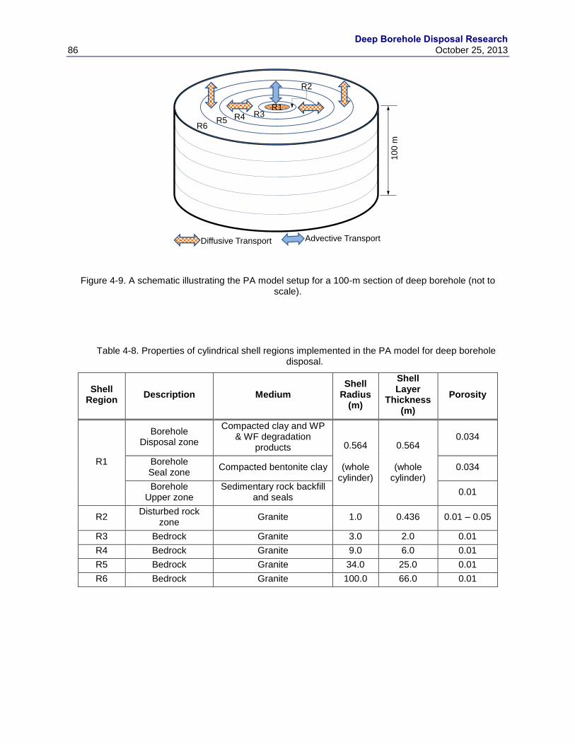
Deep Borehole Disposal Research
86 October 25, 2013
Figure 4-9. A schematic illustrating the PA model setup for a 100-m section of deep borehole (not to scale).
Table 4-8. Properties of cylindrical shell regions implemented in the PA model for deep borehole disposal.
Shell Region
Description Medium Shell
Radius (m)
Shell Layer
Thickness (m)
Porosity
R1
Borehole Disposal zone
Compacted clay and WP & WF degradation
products 0.564
(whole cylinder)
0.564
(whole cylinder)
0.034
Borehole Seal zone
Compacted bentonite clay 0.034
Borehole Upper zone
Sedimentary rock backfill and seals
0.01
R2 Disturbed rock
zone Granite 1.0 0.436 0.01 – 0.05
R3 Bedrock Granite 3.0 2.0 0.01
R4 Bedrock Granite 9.0 6.0 0.01
R5 Bedrock Granite 34.0 25.0 0.01
R6 Bedrock Granite 100.0 66.0 0.01
R6R5 R4 R3
R2
R1
Advective TransportDiffusive Transport
10
0 m

Deep Borehole Disposal Research October 25, 2013 87
4.4.2 Performance Assessment Analysis Results
This section discusses the updated PA analysis results to evaluate the DBD concept. The current
PA analysis was conducted for disposal of commercial SNF in the central borehole of an array of
81 boreholes described in the site-scale thermal-hydrologic model analysis (Section 4.2.1). The
PA analysis results are presented in terms of (1) the mean RN mass flux from the disposal
subsystems (i.e., disposal zone, seal zone and upper zone) of the central borehole as the
intermediate metrics of the system performance and (2) the mean annual dose (mrem/yr) for
individual radionuclides at a “hypothetical” biosphere above the disposal system. The model
analysis was performed probabilistically, with 100 realizations, over a time period of
1,000,000 yr.
The PA model assumes a hypothetical biosphere at the groundwater pumping location above the
repository, and uses the International Atomic Energy Agency’s (IAEA) BIOMASS Example
Reference Biosphere 1B (ERB 1B) dose model (IAEA 2003) to convert the dissolved
radionuclide concentrations in the groundwater to an estimate of annual dose to a receptor. The
model assumes that radionuclides are contained in groundwater extracted at a rate of
1×10⁴ m
3/year from the aquifer overlying the disposal system, and a receptor in the affected
biosphere community consumes the “contaminated” water at a rate of 1.2 m3/year (IAEA 2003).
4.4.2.1 Reference Case Analysis
The reference case uses the vertical groundwater flux in the borehole arising from the thermal-
hydrologic model results for base-case physical properties (Section 4.2.1, Figures 4-2 and 4-3).
The water flux in the central borehole of an 81-borehole array at varying depths as a function of
time are shown in Figure 4-10 to Figure 4-12 for the disposal zone, seal zone, and upper zone
respectively. The missing water flux values for the seal and upper zones at early time periods are
due to the negative water flux (i.e., downward water flux). (Note the water flux is on a log-scale,
and negative values are not shown.) The vertical water flux time-histories (both upward and
downward fluxes) in Figures 4-10 to 4-12 were input to the PA model and the water flux values
at 105 years are used for the time period from 10
5 year to 10
6 years.

Deep Borehole Disposal Research
88 October 25, 2013
Figure 4-10. Vertical groundwater flux at varying depths in the disposal zone of the central borehole of an 81-borehole array for disposal of commercial SNF calculated with the base case permeability in the
borehole and surrounding bedrock.
Figure 4-11. Vertical groundwater flux at varying depths in the seal zone of the central borehole of an 81-borehole array for disposal of commercial SNF calculated with the base case permeability in the borehole
and surrounding bedrock.
1.E-05
1.E-04
1.E-03
1.E-02
1.E-01
1.E+01 1.E+02 1.E+03 1.E+04 1.E+05
Wat
er
Flu
x (m
/yr)
Time (yrs)
Disposal Zone Vertical Groundwater Flux(Base Case Permeability; Central borehole of 81-borehole array)
5000 m 4900 m 4800 m 4700 m 4600 m 4500 m 4400 m
4300 m 4200 m 4100 m 4000 m 3900 m 3800 m 3700 m
3600 m 3500 m 3400 m 3300 m 3200 m 3100 m 3000 m
1.E-05
1.E-04
1.E-03
1.E-02
1.E-01
1.E+01 1.E+02 1.E+03 1.E+04 1.E+05
Wat
er
Flu
x (m
/yr)
Time (yrs)
Seal Zone Vertical Groundwater Flux(Base Case Permeability; Central borehole of 81-borehole array)
3000 m 2900 m 2800 m 2700 m
2600 m 2500 m 2400 m 2300 m
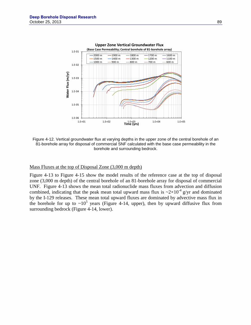
Deep Borehole Disposal Research October 25, 2013 89
Figure 4-12. Vertical groundwater flux at varying depths in the upper zone of the central borehole of an 81-borehole array for disposal of commercial SNF calculated with the base case permeability in the
borehole and surrounding bedrock.
Mass Fluxes at the top of Disposal Zone (3,000 m depth)
Figure 4-13 to Figure 4-15 show the model results of the reference case at the top of disposal
zone (3,000 m depth) of the central borehole of an 81-borehole array for disposal of commercial
UNF. Figure 4-13 shows the mean total radionuclide mass fluxes from advection and diffusion
combined, indicating that the peak mean total upward mass flux is ~2×10⁻⁴
g/yr and dominated
by the I-129 releases. These mean total upward fluxes are dominated by advective mass flux in
the borehole for up to ~105 years (Figure 4-14, upper), then by upward diffusive flux from
surrounding bedrock (Figure 4-14, lower).
1.E-06
1.E-05
1.E-04
1.E-03
1.E-02
1.E-01
1.E+01 1.E+02 1.E+03 1.E+04 1.E+05
Wat
er
Flu
x (m
/yr)
Time (yrs)
Upper Zone Vertical Groundwater Flux(Base Case Permeability; Central borehole of 81-borehole array)
2000 m 1900 m 1800 m 1700 m 1600 m1500 m 1400 m 1300 m 1200 m 1100 m1000 m 900 m 800 m 700 m 600 m

Deep Borehole Disposal Research
90 October 25, 2013
Figure 4-13. Model result of the reference case for mean total mass flux at the top of disposal zone (3,000 m depth) of the central borehole of an 81-borehole array for disposal of commercial UNF.
The peak mean lateral diffusive flux from the borehole into the bedrock (~5×10⁴
g/yr) (upper
plot of Figure 4-15) is greater than the total upward flux (Figure 4-13) and is dominated by the
Np-237 mass flux. Note that the discontinuous curves (upper plot of Figure 4-15) are due to the
back-diffusive mass flux (i.e., negative diffusive flux), which is not shown in the figure with the
mass flux (y-axis) on a log scale. The mean lateral diffusive flux in outer bedrock shells are
dominated by I-129, since other radionuclides are retarded by sorption on the bedrock materials.
The lower plot of Figure 4-15 shows the mean diffusive mass flux from Shell Region R5 (second
to the last shell; see Table 4-13), and I-129 mean mass flux has reached a steady state at
~5×10⁵
g/yr after ~105 years.
1.E-16
1.E-15
1.E-14
1.E-13
1.E-12
1.E-11
1.E-10
1.E-09
1.E-08
1.E-07
1.E-06
1.E-05
1.E-04
1.E-03
1.E-02
1.E+00 1.E+01 1.E+02 1.E+03 1.E+04 1.E+05 1.E+06
Mas
s Fl
ux
(g/y
r)
Time (years)
Mean Total Mass Flux - Disposal Zone Top(Base Case Permeability; 3,000 m depth)
Ac-227 Am-241 Am-243 C-14 Cl-36 Cm-245 Cs-135 Cs-137 I-129Nb-93 Np-237 Pa-231 Pb-210 Pd-107 Pu-238 Pu-239 Pu-240 Pu-241Pu-242 Ra-226 Ra-228 Sb-126 Se-79 Sn-126 Sr-90 Tc-99 Th-229Th-230 Th-232 U-232 U-233 U-234 U-235 U-236 U-238 Zr-93
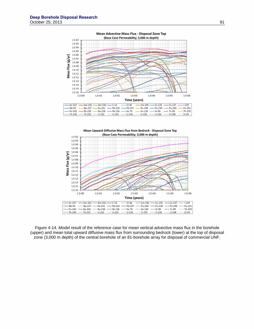
Deep Borehole Disposal Research October 25, 2013 91
Figure 4-14. Model result of the reference case for mean vertical advective mass flux in the borehole (upper) and mean total upward diffusive mass flux from surrounding bedrock (lower) at the top of disposal
zone (3,000 m depth) of the central borehole of an 81-borehole array for disposal of commercial UNF.
1.E-16
1.E-15
1.E-14
1.E-13
1.E-12
1.E-11
1.E-10
1.E-09
1.E-08
1.E-07
1.E-06
1.E-05
1.E-04
1.E-03
1.E-02
1.E+00 1.E+01 1.E+02 1.E+03 1.E+04 1.E+05 1.E+06
Mas
s Fl
ux
(g/y
r)
Time (years)
Mean Advective Mass Flux - Disposal Zone Top(Base Case Permeability; 3,000 m depth)
Ac-227 Am-241 Am-243 C-14 Cl-36 Cm-245 Cs-135 Cs-137 I-129Nb-93 Np-237 Pa-231 Pb-210 Pd-107 Pu-238 Pu-239 Pu-240 Pu-241Pu-242 Ra-226 Ra-228 Sb-126 Se-79 Sn-126 Sr-90 Tc-99 Th-229Th-230 Th-232 U-232 U-233 U-234 U-235 U-236 U-238 Zr-93
1.E-16
1.E-15
1.E-14
1.E-13
1.E-12
1.E-11
1.E-10
1.E-09
1.E-08
1.E-07
1.E-06
1.E-05
1.E-04
1.E-03
1.E-02
1.E+00 1.E+01 1.E+02 1.E+03 1.E+04 1.E+05 1.E+06
Mas
s Fl
ux
(g/y
r)
Time (years)
Mean Upward Diffusive Mass Flux from Bedrock - Disposal Zone Top(Base Case Permeability; 3,000 m depth)
Ac-227 Am-241 Am-243 C-14 Cl-36 Cm-245 Cs-135 Cs-137 I-129Nb-93 Np-237 Pa-231 Pb-210 Pd-107 Pu-238 Pu-239 Pu-240 Pu-241Pu-242 Ra-226 Ra-228 Sb-126 Se-79 Sn-126 Sr-90 Tc-99 Th-229Th-230 Th-232 U-232 U-233 U-234 U-235 U-236 U-238 Zr-93
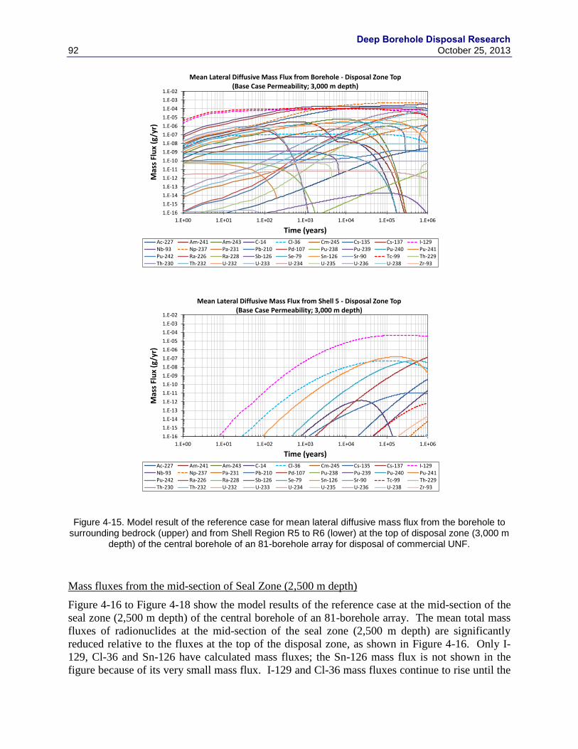
Deep Borehole Disposal Research
92 October 25, 2013
Figure 4-15. Model result of the reference case for mean lateral diffusive mass flux from the borehole to surrounding bedrock (upper) and from Shell Region R5 to R6 (lower) at the top of disposal zone (3,000 m
depth) of the central borehole of an 81-borehole array for disposal of commercial UNF.
Mass fluxes from the mid-section of Seal Zone (2,500 m depth)
Figure 4-16 to Figure 4-18 show the model results of the reference case at the mid-section of the
seal zone (2,500 m depth) of the central borehole of an 81-borehole array. The mean total mass
fluxes of radionuclides at the mid-section of the seal zone (2,500 m depth) are significantly
reduced relative to the fluxes at the top of the disposal zone, as shown in Figure 4-16. Only I-
129, Cl-36 and Sn-126 have calculated mass fluxes; the Sn-126 mass flux is not shown in the
figure because of its very small mass flux. I-129 and Cl-36 mass fluxes continue to rise until the
1.E-16
1.E-15
1.E-14
1.E-13
1.E-12
1.E-11
1.E-10
1.E-09
1.E-08
1.E-07
1.E-06
1.E-05
1.E-04
1.E-03
1.E-02
1.E+00 1.E+01 1.E+02 1.E+03 1.E+04 1.E+05 1.E+06
Mas
s Fl
ux
(g/y
r)
Time (years)
Mean Lateral Diffusive Mass Flux from Borehole - Disposal Zone Top(Base Case Permeability; 3,000 m depth)
Ac-227 Am-241 Am-243 C-14 Cl-36 Cm-245 Cs-135 Cs-137 I-129Nb-93 Np-237 Pa-231 Pb-210 Pd-107 Pu-238 Pu-239 Pu-240 Pu-241Pu-242 Ra-226 Ra-228 Sb-126 Se-79 Sn-126 Sr-90 Tc-99 Th-229Th-230 Th-232 U-232 U-233 U-234 U-235 U-236 U-238 Zr-93
1.E-16
1.E-15
1.E-14
1.E-13
1.E-12
1.E-11
1.E-10
1.E-09
1.E-08
1.E-07
1.E-06
1.E-05
1.E-04
1.E-03
1.E-02
1.E+00 1.E+01 1.E+02 1.E+03 1.E+04 1.E+05 1.E+06
Mas
s Fl
ux
(g/y
r)
Time (years)
Mean Lateral Diffusive Mass Flux from Shell 5 - Disposal Zone Top(Base Case Permeability; 3,000 m depth)
Ac-227 Am-241 Am-243 C-14 Cl-36 Cm-245 Cs-135 Cs-137 I-129Nb-93 Np-237 Pa-231 Pb-210 Pd-107 Pu-238 Pu-239 Pu-240 Pu-241Pu-242 Ra-226 Ra-228 Sb-126 Se-79 Sn-126 Sr-90 Tc-99 Th-229Th-230 Th-232 U-232 U-233 U-234 U-235 U-236 U-238 Zr-93
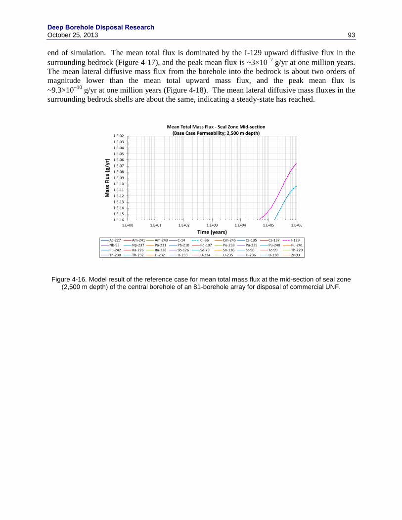
Deep Borehole Disposal Research October 25, 2013 93
end of simulation. The mean total flux is dominated by the I-129 upward diffusive flux in the
surrounding bedrock (Figure 4-17), and the peak mean flux is ~3×10⁷
g/yr at one million years.
The mean lateral diffusive mass flux from the borehole into the bedrock is about two orders of
magnitude lower than the mean total upward mass flux, and the peak mean flux is
~9.3×10¹⁰
g/yr at one million years (Figure 4-18). The mean lateral diffusive mass fluxes in the
surrounding bedrock shells are about the same, indicating a steady-state has reached.
Figure 4-16. Model result of the reference case for mean total mass flux at the mid-section of seal zone (2,500 m depth) of the central borehole of an 81-borehole array for disposal of commercial UNF.
1.E-16
1.E-15
1.E-14
1.E-13
1.E-12
1.E-11
1.E-10
1.E-09
1.E-08
1.E-07
1.E-06
1.E-05
1.E-04
1.E-03
1.E-02
1.E+00 1.E+01 1.E+02 1.E+03 1.E+04 1.E+05 1.E+06
Mas
s Fl
ux
(g/y
r)
Time (years)
Mean Total Mass Flux - Seal Zone Mid-section(Base Case Permeability; 2,500 m depth)
Ac-227 Am-241 Am-243 C-14 Cl-36 Cm-245 Cs-135 Cs-137 I-129Nb-93 Np-237 Pa-231 Pb-210 Pd-107 Pu-238 Pu-239 Pu-240 Pu-241Pu-242 Ra-226 Ra-228 Sb-126 Se-79 Sn-126 Sr-90 Tc-99 Th-229Th-230 Th-232 U-232 U-233 U-234 U-235 U-236 U-238 Zr-93
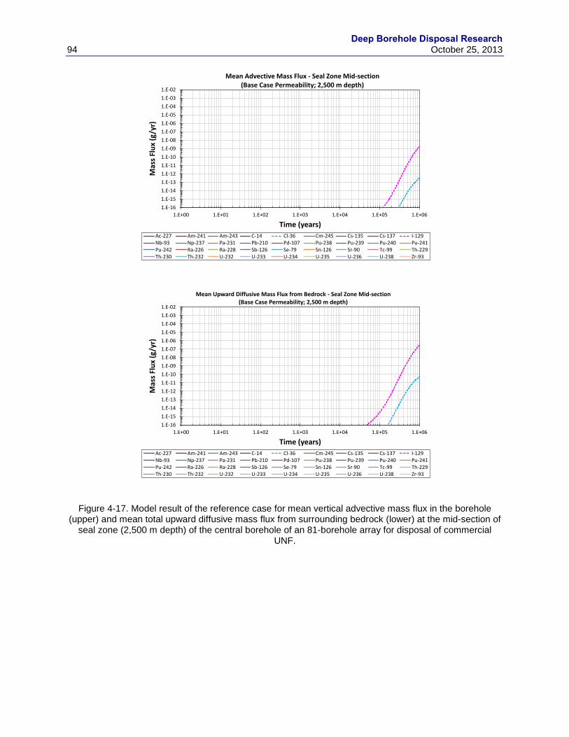
Deep Borehole Disposal Research
94 October 25, 2013
Figure 4-17. Model result of the reference case for mean vertical advective mass flux in the borehole (upper) and mean total upward diffusive mass flux from surrounding bedrock (lower) at the mid-section of
seal zone (2,500 m depth) of the central borehole of an 81-borehole array for disposal of commercial UNF.
1.E-16
1.E-15
1.E-14
1.E-13
1.E-12
1.E-11
1.E-10
1.E-09
1.E-08
1.E-07
1.E-06
1.E-05
1.E-04
1.E-03
1.E-02
1.E+00 1.E+01 1.E+02 1.E+03 1.E+04 1.E+05 1.E+06
Mas
s Fl
ux
(g/y
r)
Time (years)
Mean Advective Mass Flux - Seal Zone Mid-section(Base Case Permeability; 2,500 m depth)
Ac-227 Am-241 Am-243 C-14 Cl-36 Cm-245 Cs-135 Cs-137 I-129Nb-93 Np-237 Pa-231 Pb-210 Pd-107 Pu-238 Pu-239 Pu-240 Pu-241Pu-242 Ra-226 Ra-228 Sb-126 Se-79 Sn-126 Sr-90 Tc-99 Th-229Th-230 Th-232 U-232 U-233 U-234 U-235 U-236 U-238 Zr-93
1.E-16
1.E-15
1.E-14
1.E-13
1.E-12
1.E-11
1.E-10
1.E-09
1.E-08
1.E-07
1.E-06
1.E-05
1.E-04
1.E-03
1.E-02
1.E+00 1.E+01 1.E+02 1.E+03 1.E+04 1.E+05 1.E+06
Mas
s Fl
ux
(g/y
r)
Time (years)
Mean Upward Diffusive Mass Flux from Bedrock - Seal Zone Mid-section(Base Case Permeability; 2,500 m depth)
Ac-227 Am-241 Am-243 C-14 Cl-36 Cm-245 Cs-135 Cs-137 I-129Nb-93 Np-237 Pa-231 Pb-210 Pd-107 Pu-238 Pu-239 Pu-240 Pu-241Pu-242 Ra-226 Ra-228 Sb-126 Se-79 Sn-126 Sr-90 Tc-99 Th-229Th-230 Th-232 U-232 U-233 U-234 U-235 U-236 U-238 Zr-93
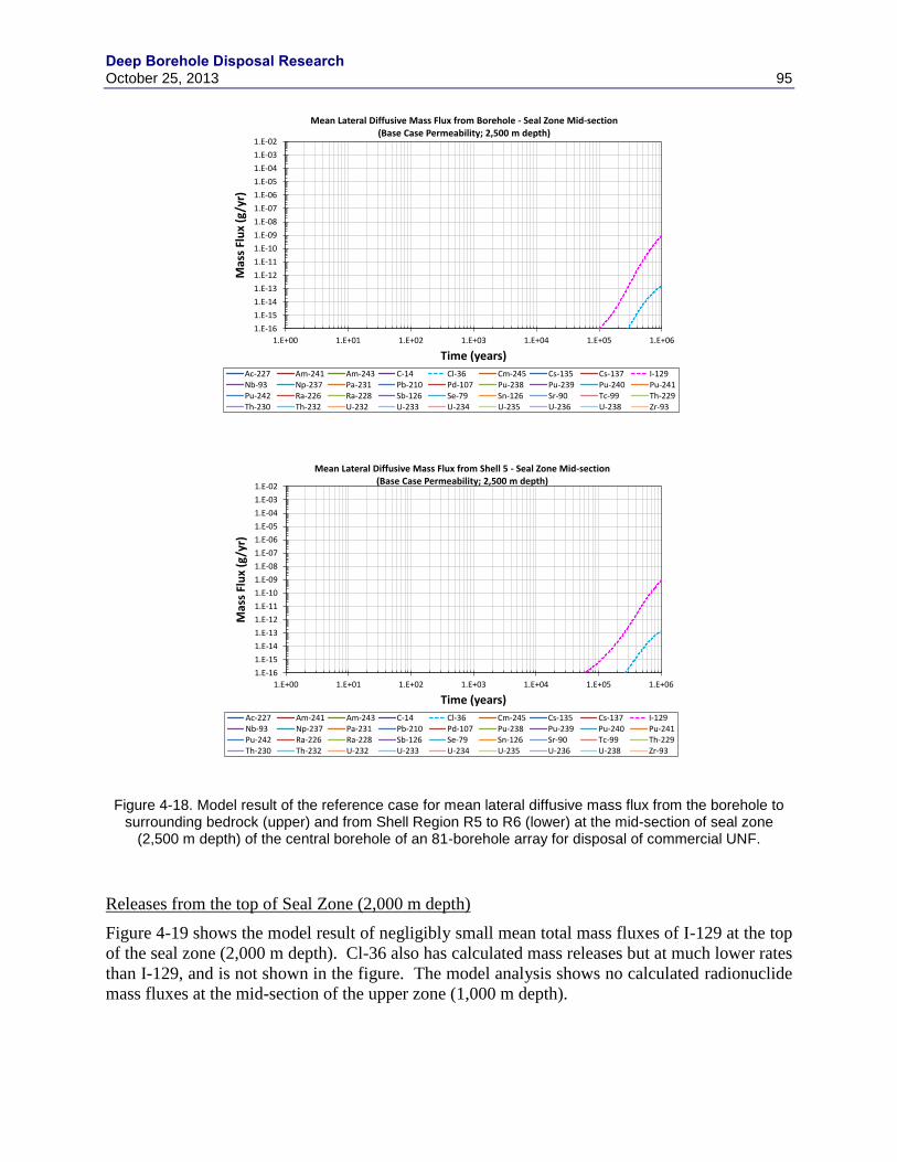
Deep Borehole Disposal Research October 25, 2013 95
Figure 4-18. Model result of the reference case for mean lateral diffusive mass flux from the borehole to surrounding bedrock (upper) and from Shell Region R5 to R6 (lower) at the mid-section of seal zone
(2,500 m depth) of the central borehole of an 81-borehole array for disposal of commercial UNF.
Releases from the top of Seal Zone (2,000 m depth)
Figure 4-19 shows the model result of negligibly small mean total mass fluxes of I-129 at the top
of the seal zone (2,000 m depth). Cl-36 also has calculated mass releases but at much lower rates
than I-129, and is not shown in the figure. The model analysis shows no calculated radionuclide
mass fluxes at the mid-section of the upper zone (1,000 m depth).
1.E-16
1.E-15
1.E-14
1.E-13
1.E-12
1.E-11
1.E-10
1.E-09
1.E-08
1.E-07
1.E-06
1.E-05
1.E-04
1.E-03
1.E-02
1.E+00 1.E+01 1.E+02 1.E+03 1.E+04 1.E+05 1.E+06
Mas
s Fl
ux
(g/y
r)
Time (years)
Mean Lateral Diffusive Mass Flux from Borehole - Seal Zone Mid-section(Base Case Permeability; 2,500 m depth)
Ac-227 Am-241 Am-243 C-14 Cl-36 Cm-245 Cs-135 Cs-137 I-129Nb-93 Np-237 Pa-231 Pb-210 Pd-107 Pu-238 Pu-239 Pu-240 Pu-241Pu-242 Ra-226 Ra-228 Sb-126 Se-79 Sn-126 Sr-90 Tc-99 Th-229Th-230 Th-232 U-232 U-233 U-234 U-235 U-236 U-238 Zr-93
1.E-16
1.E-15
1.E-14
1.E-13
1.E-12
1.E-11
1.E-10
1.E-09
1.E-08
1.E-07
1.E-06
1.E-05
1.E-04
1.E-03
1.E-02
1.E+00 1.E+01 1.E+02 1.E+03 1.E+04 1.E+05 1.E+06
Mas
s Fl
ux
(g/y
r)
Time (years)
Mean Lateral Diffusive Mass Flux from Shell 5 - Seal Zone Mid-section(Base Case Permeability; 2,500 m depth)
Ac-227 Am-241 Am-243 C-14 Cl-36 Cm-245 Cs-135 Cs-137 I-129Nb-93 Np-237 Pa-231 Pb-210 Pd-107 Pu-238 Pu-239 Pu-240 Pu-241Pu-242 Ra-226 Ra-228 Sb-126 Se-79 Sn-126 Sr-90 Tc-99 Th-229Th-230 Th-232 U-232 U-233 U-234 U-235 U-236 U-238 Zr-93

Deep Borehole Disposal Research
96 October 25, 2013
Figure 4-19. Model result of the reference case for mean total mass flux at the top of seal zone (2,000 m depth) of the central borehole of an 81-borehole array for disposal of commercial UNF.
4.4.2.2 Sensitivity Analysis
Sensitivity analyses were conducted to evaluate the DBD system responses to changes in the
model parameters of the following four cases:
Groundwater flux in the borehole calculated with the permeability values from a study by
Stober and Bucher (2007) (referred to as Alternative Permeability Case).
Reference Case vertical groundwater flux in the borehole increased by a factor of 10
(referred to as High Groundwater Flux Case).
SNF degradation rate increased by a factor of 100 (referred to as Enhanced SNF
Degradation Case).
Reference Case vertical groundwater flux in the borehole increased by a factor of 10 and
SNF degradation rate increased by a factor of 100 (referred to as Combined High
Groundwater Flux & Enhanced SNF Degradation Case).
Alternative Permeability Case
An empirical relationship for the permeability of the crystalline basement as a function of depth
was reported by Stober and Bucher (2007). The permeability relationship (referred to as Stober
and Bucher permeability in this report) was used as an alternative permeability function, and a
sensitivity analysis was conducted to evaluate effect of the alternative permeability on the deep
borehole repository performance.
1.E-16
1.E-15
1.E-14
1.E-13
1.E-12
1.E-11
1.E-10
1.E-09
1.E-08
1.E-07
1.E-06
1.E-05
1.E-04
1.E-03
1.E-02
1.E+00 1.E+01 1.E+02 1.E+03 1.E+04 1.E+05 1.E+06
Mas
s Fl
ux
(g/y
r)
Time (years)
Mean Total Mass Flux - Seal Zone Top(Base Case Permeability; 2,000 m depth)
Ac-227 Am-241 Am-243 C-14 Cl-36 Cm-245 Cs-135 Cs-137 I-129Nb-93 Np-237 Pa-231 Pb-210 Pd-107 Pu-238 Pu-239 Pu-240 Pu-241Pu-242 Ra-226 Ra-228 Sb-126 Se-79 Sn-126 Sr-90 Tc-99 Th-229Th-230 Th-232 U-232 U-233 U-234 U-235 U-236 U-238 Zr-93
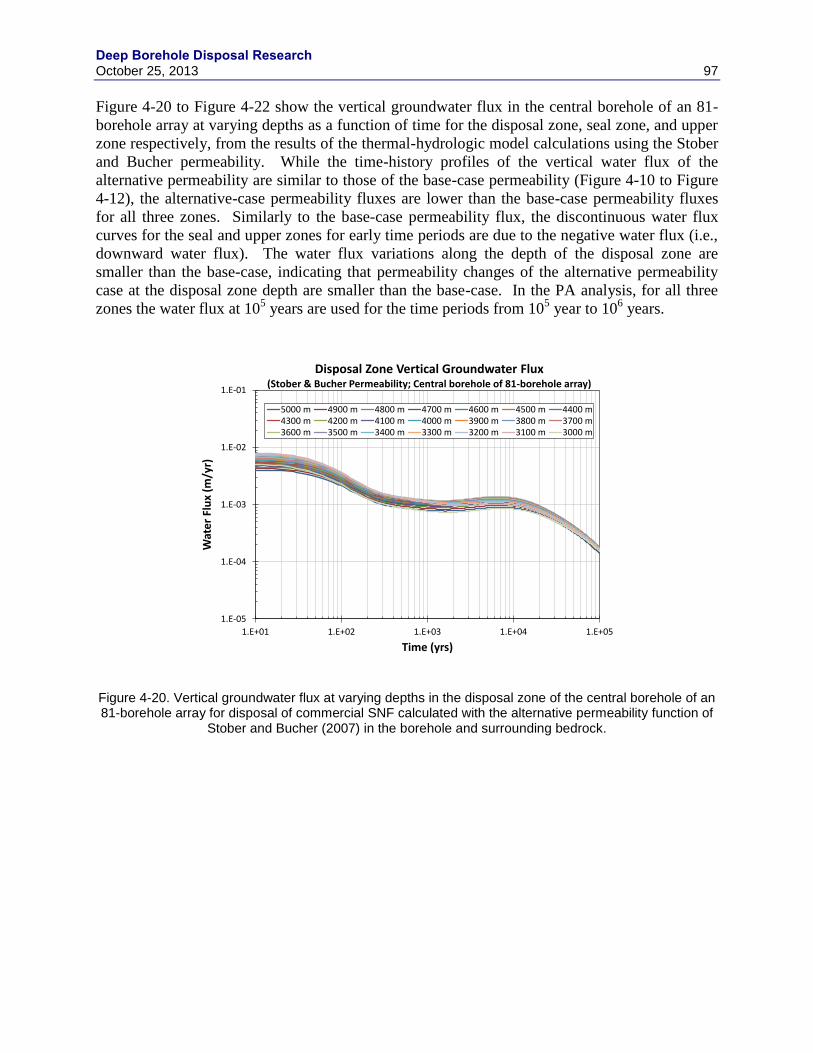
Deep Borehole Disposal Research October 25, 2013 97
Figure 4-20 to Figure 4-22 show the vertical groundwater flux in the central borehole of an 81-
borehole array at varying depths as a function of time for the disposal zone, seal zone, and upper
zone respectively, from the results of the thermal-hydrologic model calculations using the Stober
and Bucher permeability. While the time-history profiles of the vertical water flux of the
alternative permeability are similar to those of the base-case permeability (Figure 4-10 to Figure
4-12), the alternative-case permeability fluxes are lower than the base-case permeability fluxes
for all three zones. Similarly to the base-case permeability flux, the discontinuous water flux
curves for the seal and upper zones for early time periods are due to the negative water flux (i.e.,
downward water flux). The water flux variations along the depth of the disposal zone are
smaller than the base-case, indicating that permeability changes of the alternative permeability
case at the disposal zone depth are smaller than the base-case. In the PA analysis, for all three
zones the water flux at 105 years are used for the time periods from 10
5 year to 10
6 years.
Figure 4-20. Vertical groundwater flux at varying depths in the disposal zone of the central borehole of an 81-borehole array for disposal of commercial SNF calculated with the alternative permeability function of
Stober and Bucher (2007) in the borehole and surrounding bedrock.
1.E-05
1.E-04
1.E-03
1.E-02
1.E-01
1.E+01 1.E+02 1.E+03 1.E+04 1.E+05
Wat
er
Flu
x (m
/yr)
Time (yrs)
Disposal Zone Vertical Groundwater Flux(Stober & Bucher Permeability; Central borehole of 81-borehole array)
5000 m 4900 m 4800 m 4700 m 4600 m 4500 m 4400 m4300 m 4200 m 4100 m 4000 m 3900 m 3800 m 3700 m3600 m 3500 m 3400 m 3300 m 3200 m 3100 m 3000 m
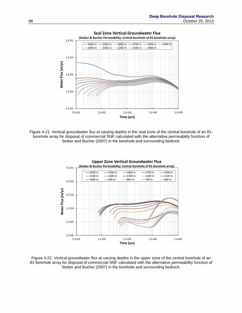
Deep Borehole Disposal Research
98 October 25, 2013
Figure 4-21. Vertical groundwater flux at varying depths in the seal zone of the central borehole of an 81-borehole array for disposal of commercial SNF calculated with the alternative permeability function of
Stober and Bucher (2007) in the borehole and surrounding bedrock.
Figure 4-22. Vertical groundwater flux at varying depths in the upper zone of the central borehole of an 81-borehole array for disposal of commercial SNF calculated with the alternative permeability function of
Stober and Bucher (2007) in the borehole and surrounding bedrock.
1.E-05
1.E-04
1.E-03
1.E-02
1.E-01
1.E+01 1.E+02 1.E+03 1.E+04 1.E+05
Wat
er
Flu
x (m
/yr)
Time (yrs)
Seal Zone Vertical Groundwater Flux(Stober & Bucher Permeability; Central borehole of 81-borehole array)
3000 m 2900 m 2800 m 2700 m 2600 m 2500 m2400 m 2300 m 2200 m 2100 m 2000 m
1.E-06
1.E-05
1.E-04
1.E-03
1.E-02
1.E-01
1.E+01 1.E+02 1.E+03 1.E+04 1.E+05
Wat
er
Flu
x (m
/yr)
Time (yrs)
Upper Zone Vertical Groundwater Flux(Stober & Bucher Permeability; Central borehole of 81-borehole array)
2000 m 1900 m 1800 m 1700 m 1600 m1500 m 1400 m 1300 m 1200 m 1100 m1000 m 900 m 800 m 700 m 600 m

Deep Borehole Disposal Research October 25, 2013 99
Releases from the top of Disposal Zone (3,000 m depth)
Figure 4-23 to Figure 4-25 show the model results of the alternative permeability case at the top
of disposal zone (3,000 m depth) of the central borehole of an 81-borehole array for disposal of
commercial UNF. As expected from the groundwater flux profiles of the alternative
permeability case, the borehole system responses in terms of the radionuclide mass fluxes are
similar to the reference case mass fluxes. Figure 4-23 shows the model result of the alternative
permeability case for the mean total mass flux at the top of disposal zone (3,000 m depth). The
mean total mass flux increases steadily with time, and the upward advective flux in the borehole
(upper figure of Figure 4-24) dominates the total mass flux for up to ~105 years. Afterward, the
upward diffusive mass flux from the surrounding bedrock dominates the total mass flux (lower
figure of Figure 4-24). For up to ~105 years, the mean total mass flux of the alternative
permeability case is slightly lower than the reference-case total mass flux, after which it becomes
about the same as the reference-case mean total mass flux. For the entire simulation time period,
I-129 is the dominant radionuclide contributing to the total mass flux, with a peak mean total
upward radionuclide mass flux of ~2×10⁴
g/yr at the top of the disposal zone (Figure 4-23).
Figure 4-23. Model result of the alternative permeability case for mean total mass flux at the top of disposal zone (3,000 m depth) of the central borehole of an 81-borehole array for disposal of commercial
UNF.
1.E-16
1.E-15
1.E-14
1.E-13
1.E-12
1.E-11
1.E-10
1.E-09
1.E-08
1.E-07
1.E-06
1.E-05
1.E-04
1.E-03
1.E-02
1.E+00 1.E+01 1.E+02 1.E+03 1.E+04 1.E+05 1.E+06
Mas
s Fl
ux
(g/y
r)
Time (years)
Mean Total Mass Flux - Disposal Zone Top(Stober Permeability Case; 3,000 m depth)
Ac-227 Am-241 Am-243 C-14 Cl-36 Cm-245 Cs-135 Cs-137 I-129Nb-93 Np-237 Pa-231 Pb-210 Pd-107 Pu-238 Pu-239 Pu-240 Pu-241Pu-242 Ra-226 Ra-228 Sb-126 Se-79 Sn-126 Sr-90 Tc-99 Th-229Th-230 Th-232 U-232 U-233 U-234 U-235 U-236 U-238 Zr-93

Deep Borehole Disposal Research
100 October 25, 2013
Figure 4-24. Model result of the alternative permeability case for mean vertical advective mass flux in the borehole (upper) and mean total upward diffusive mass flux from surrounding bedrock (lower) at the top
of disposal zone (3,000 m depth) of the central borehole of an 81-borehole array for disposal of commercial UNF.
The lateral diffusive mass flux into the surrounding bedrock (Figure 4-25) is close to the
reference case diffusive flux (Figure 4-15). The peak mean lateral diffusive flux from the
borehole into the bedrock is dominated by the Np-237 mass flux at ~5×10⁴
g/yr at ~200,000
years (upper figure of Figure 4-25), and the peak mean lateral flux is greater than the total
upward flux (Figure 4-23). The discontinuous curves (upper figure of Figure 4-25) are due to the
back-diffusive mass flux (i.e., negative diffusive flux), and is not shown in the figure with the
1.E-16
1.E-15
1.E-14
1.E-13
1.E-12
1.E-11
1.E-10
1.E-09
1.E-08
1.E-07
1.E-06
1.E-05
1.E-04
1.E-03
1.E-02
1.E+00 1.E+01 1.E+02 1.E+03 1.E+04 1.E+05 1.E+06
Mas
s Fl
ux
(g/y
r)
Time (years)
Mean Advective Mass Flux - Disposal Zone Top(Stober Permeability Case; 3,000 m depth)
Ac-227 Am-241 Am-243 C-14 Cl-36 Cm-245 Cs-135 Cs-137 I-129Nb-93 Np-237 Pa-231 Pb-210 Pd-107 Pu-238 Pu-239 Pu-240 Pu-241Pu-242 Ra-226 Ra-228 Sb-126 Se-79 Sn-126 Sr-90 Tc-99 Th-229Th-230 Th-232 U-232 U-233 U-234 U-235 U-236 U-238 Zr-93
1.E-16
1.E-15
1.E-14
1.E-13
1.E-12
1.E-11
1.E-10
1.E-09
1.E-08
1.E-07
1.E-06
1.E-05
1.E-04
1.E-03
1.E-02
1.E+00 1.E+01 1.E+02 1.E+03 1.E+04 1.E+05 1.E+06
Mas
s Fl
ux
(g/y
r)
Time (years)
Mean Upward Diffusive Mass Flux from Bedrock - Disposal Zone Top(Stober Permeability Case; 3,000 m depth)
Ac-227 Am-241 Am-243 C-14 Cl-36 Cm-245 Cs-135 Cs-137 I-129Nb-93 Np-237 Pa-231 Pb-210 Pd-107 Pu-238 Pu-239 Pu-240 Pu-241Pu-242 Ra-226 Ra-228 Sb-126 Se-79 Sn-126 Sr-90 Tc-99 Th-229Th-230 Th-232 U-232 U-233 U-234 U-235 U-236 U-238 Zr-93

Deep Borehole Disposal Research October 25, 2013 101
mass flux (y-axis) on a log scale. As with the reference case, the mean lateral diffusive flux in
outer bedrock shells is dominated by I-129, since other radionuclides are retarded by sorption on
the bedrock materials. The mean diffusive mass flux from Shell Region R5 (second to the last
shell; see Table 4-13) reaches a steady state at ~5×10⁵
g/yr after ~105 years (lower figure of
Figure 4-25).
Figure 4-25. Model result of the alternative permeability case for mean lateral diffusive mass flux from the borehole to surrounding bedrock (left) and from Shell Region R5 to R6 (right) at the top of disposal zone
(3,000 m depth) of the central borehole of an 81-borehole array for disposal of commercial UNF.
1.E-16
1.E-15
1.E-14
1.E-13
1.E-12
1.E-11
1.E-10
1.E-09
1.E-08
1.E-07
1.E-06
1.E-05
1.E-04
1.E-03
1.E-02
1.E+00 1.E+01 1.E+02 1.E+03 1.E+04 1.E+05 1.E+06
Mas
s Fl
ux
(g/y
r)
Time (years)
Mean Lateral Diffusive Mass Flux from Borehole - Disposal Zone Top(Stober Permeability Case; 3,000 m depth)
Ac-227 Am-241 Am-243 C-14 Cl-36 Cm-245 Cs-135 Cs-137 I-129Nb-93 Np-237 Pa-231 Pb-210 Pd-107 Pu-238 Pu-239 Pu-240 Pu-241Pu-242 Ra-226 Ra-228 Sb-126 Se-79 Sn-126 Sr-90 Tc-99 Th-229Th-230 Th-232 U-232 U-233 U-234 U-235 U-236 U-238 Zr-93
1.E-16
1.E-15
1.E-14
1.E-13
1.E-12
1.E-11
1.E-10
1.E-09
1.E-08
1.E-07
1.E-06
1.E-05
1.E-04
1.E-03
1.E-02
1.E+00 1.E+01 1.E+02 1.E+03 1.E+04 1.E+05 1.E+06
Mas
s Fl
ux
(g/y
r)
Time (years)
Mean Lateral Diffusive Mass Flux from Shell 5 - Disposal Zone Top(Stober Permeability Case; 3,000 m depth)
Ac-227 Am-241 Am-243 C-14 Cl-36 Cm-245 Cs-135 Cs-137 I-129Nb-93 Np-237 Pa-231 Pb-210 Pd-107 Pu-238 Pu-239 Pu-240 Pu-241Pu-242 Ra-226 Ra-228 Sb-126 Se-79 Sn-126 Sr-90 Tc-99 Th-229Th-230 Th-232 U-232 U-233 U-234 U-235 U-236 U-238 Zr-93
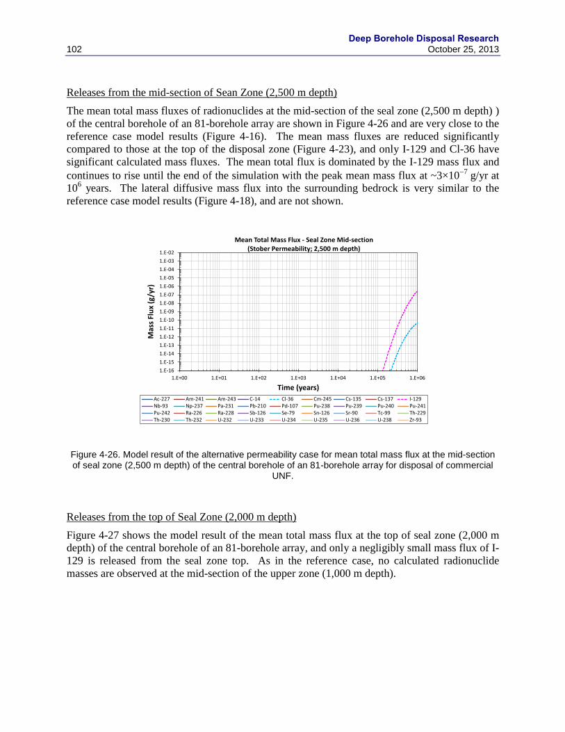
Deep Borehole Disposal Research
102 October 25, 2013
Releases from the mid-section of Sean Zone (2,500 m depth)
The mean total mass fluxes of radionuclides at the mid-section of the seal zone (2,500 m depth) )
of the central borehole of an 81-borehole array are shown in Figure 4-26 and are very close to the
reference case model results (Figure 4-16). The mean mass fluxes are reduced significantly
compared to those at the top of the disposal zone (Figure 4-23), and only I-129 and Cl-36 have
significant calculated mass fluxes. The mean total flux is dominated by the I-129 mass flux and
continues to rise until the end of the simulation with the peak mean mass flux at ~3×10⁷
g/yr at
106 years. The lateral diffusive mass flux into the surrounding bedrock is very similar to the
reference case model results (Figure 4-18), and are not shown.
Figure 4-26. Model result of the alternative permeability case for mean total mass flux at the mid-section of seal zone (2,500 m depth) of the central borehole of an 81-borehole array for disposal of commercial
UNF.
Releases from the top of Seal Zone (2,000 m depth)
Figure 4-27 shows the model result of the mean total mass flux at the top of seal zone (2,000 m
depth) of the central borehole of an 81-borehole array, and only a negligibly small mass flux of I-
129 is released from the seal zone top. As in the reference case, no calculated radionuclide
masses are observed at the mid-section of the upper zone (1,000 m depth).
1.E-16
1.E-15
1.E-14
1.E-13
1.E-12
1.E-11
1.E-10
1.E-09
1.E-08
1.E-07
1.E-06
1.E-05
1.E-04
1.E-03
1.E-02
1.E+00 1.E+01 1.E+02 1.E+03 1.E+04 1.E+05 1.E+06
Mas
s Fl
ux
(g/y
r)
Time (years)
Mean Total Mass Flux - Seal Zone Mid-section(Stober Permeability; 2,500 m depth)
Ac-227 Am-241 Am-243 C-14 Cl-36 Cm-245 Cs-135 Cs-137 I-129Nb-93 Np-237 Pa-231 Pb-210 Pd-107 Pu-238 Pu-239 Pu-240 Pu-241Pu-242 Ra-226 Ra-228 Sb-126 Se-79 Sn-126 Sr-90 Tc-99 Th-229Th-230 Th-232 U-232 U-233 U-234 U-235 U-236 U-238 Zr-93

Deep Borehole Disposal Research October 25, 2013 103
Figure 4-27. Model result of the alternative permeability case for mean total mass flux at the top of seal zone (2,000 m depth) of the central borehole of an 81-borehole array for disposal of commercial UNF.
High Groundwater Flux Case
The sensitivity of the deep borehole disposal concept to vertical groundwater flux was examined
by increasing the flux by a factor of 10 relative to the reference case (Figure 4-10 to Figure 4-
12). Note that the reference-case groundwater flux is for the central borehole of an 81-borehole
array.
Releases from the Top of Disposal Zone (3,000 m depth)
Figure 4-28 to Figure 4-30 show the model results of the high groundwater flux case at the top of
disposal zone (3,000 m depth) of the central borehole of an 81-borehole array for disposal of
commercial UNF. Figure 4-28 shows the model result for the mean total RN mass fluxes. The
peak mean total mass flux is ~5×10⁴
g/yr, dominated by 129
I, and reached at much earlier times
(at ~100 years and again at ~104 years) than the reference case (Figure 4-13). The mean total
mass fluxes are dominated by advective mass flux in the borehole for the entire simulation
period; the advective mass flux is greater than the upward diffusive flux from the surrounding
bedrock due to the high water flux in the borehole (Figure 4-29). Note that the discontinuous
curve for the I-129 diffusive mass flux from the surrounding bedrock (lower figure of Figure 4-
29) is due to the back-diffusion (i.e., negative diffusive mass flux transporting the mass
downward) that results from higher I-129 dissolved concentrations in the bedrock region around
the borehole right above the top of the disposal zone; a higher mass flux of I-129 is transported
advectively upward in the borehole during the time periods when the back-diffusion occurs
(lower figure of Figure4-29).
1.E-16
1.E-15
1.E-14
1.E-13
1.E-12
1.E-11
1.E-10
1.E-09
1.E-08
1.E-07
1.E-06
1.E-05
1.E-04
1.E-03
1.E-02
1.E+00 1.E+01 1.E+02 1.E+03 1.E+04 1.E+05 1.E+06
Mas
s Fl
ux
(g/y
r)
Time (years)
Mean Total Mass Flux - Seal Zone Top(Stober Permeability; 2,000 m depth)
Ac-227 Am-241 Am-243 C-14 Cl-36 Cm-245 Cs-135 Cs-137 I-129Nb-93 Np-237 Pa-231 Pb-210 Pd-107 Pu-238 Pu-239 Pu-240 Pu-241Pu-242 Ra-226 Ra-228 Sb-126 Se-79 Sn-126 Sr-90 Tc-99 Th-229Th-230 Th-232 U-232 U-233 U-234 U-235 U-236 U-238 Zr-93

Deep Borehole Disposal Research
104 October 25, 2013
Figure 4-28. Model result of the high groundwater flux case for mean total mass flux at the top of disposal zone (3,000 m depth) of the central borehole of an 81-borehole array for disposal of commercial UNF.
The mean lateral diffusive mass flux from the borehole to the surrounding bedrock (upper figure
of Figure 4-30) is about the same order of magnitude as the mean total upward mass flux (Figure
4-28), and this demonstrates the importance of lateral diffusional transport into and within the
surrounding bedrock. The mean lateral diffusive mass flux is dominated initially by Tc-99 and
later by Np-237. Note that discontinuous lateral diffusive mass flux curves of some
radionuclides in the figure are due also to the back-diffusion from the bedrock region right next
to the borehole (Shell Region R2, Table 4-13). The mean lateral diffusive flux in outer bedrock
shells is dominated by I-129, since other radionuclides are retarded by sorption on the bedrock
materials. Figure 4-30 (lower figure) shows the mean diffusive mass flux from Shell Region R5
(second to the last shell; see Table 4-13), and the I-129 mean mass flux has reached a steady
state at ~5×10⁵
g/yr after ~105 years.
1.E-16
1.E-15
1.E-14
1.E-13
1.E-12
1.E-11
1.E-10
1.E-09
1.E-08
1.E-07
1.E-06
1.E-05
1.E-04
1.E-03
1.E-02
1.E+00 1.E+01 1.E+02 1.E+03 1.E+04 1.E+05 1.E+06
Mas
s Fl
ux
(g/y
r)
Time (years)
Mean Total Mass Flux - Disposal Zone Top(10X Base Case GW Flux; 3,000 m depth)
Ac-227 Am-241 Am-243 C-14 Cl-36 Cm-245 Cs-135 Cs-137 I-129Nb-93 Np-237 Pa-231 Pb-210 Pd-107 Pu-238 Pu-239 Pu-240 Pu-241Pu-242 Ra-226 Ra-228 Sb-126 Se-79 Sn-126 Sr-90 Tc-99 Th-229Th-230 Th-232 U-232 U-233 U-234 U-235 U-236 U-238 Zr-93

Deep Borehole Disposal Research October 25, 2013 105
Figure 4-29. Model result of the high groundwater flux case for mean vertical advective mass flux in the borehole (upper) and mean total upward diffusive mass flux from surrounding bedrock (lower) at the top
of disposal zone (3,000 m depth) of the central borehole of an 81-borehole array for disposal of commercial UNF.
1.E-16
1.E-15
1.E-14
1.E-13
1.E-12
1.E-11
1.E-10
1.E-09
1.E-08
1.E-07
1.E-06
1.E-05
1.E-04
1.E-03
1.E-02
1.E+00 1.E+01 1.E+02 1.E+03 1.E+04 1.E+05 1.E+06
Mas
s Fl
ux
(g/y
r)
Time (years)
Mean Advective Mass Flux - Disposal Zone Top(10X Base CaseGW Flux; 3,000 m depth)
Ac-227 Am-241 Am-243 C-14 Cl-36 Cm-245 Cs-135 Cs-137 I-129Nb-93 Np-237 Pa-231 Pb-210 Pd-107 Pu-238 Pu-239 Pu-240 Pu-241Pu-242 Ra-226 Ra-228 Sb-126 Se-79 Sn-126 Sr-90 Tc-99 Th-229Th-230 Th-232 U-232 U-233 U-234 U-235 U-236 U-238 Zr-93
1.E-16
1.E-15
1.E-14
1.E-13
1.E-12
1.E-11
1.E-10
1.E-09
1.E-08
1.E-07
1.E-06
1.E-05
1.E-04
1.E-03
1.E-02
1.E+00 1.E+01 1.E+02 1.E+03 1.E+04 1.E+05 1.E+06
Mas
s Fl
ux
(g/y
r)
Time (years)
Mean Upward Diffusive Mass Flux from Bedrock - Disposal Zone Top(10X Base Case GW Flux; 3,000 m depth)
Ac-227 Am-241 Am-243 C-14 Cl-36 Cm-245 Cs-135 Cs-137 I-129Nb-93 Np-237 Pa-231 Pb-210 Pd-107 Pu-238 Pu-239 Pu-240 Pu-241Pu-242 Ra-226 Ra-228 Sb-126 Se-79 Sn-126 Sr-90 Tc-99 Th-229Th-230 Th-232 U-232 U-233 U-234 U-235 U-236 U-238 Zr-93
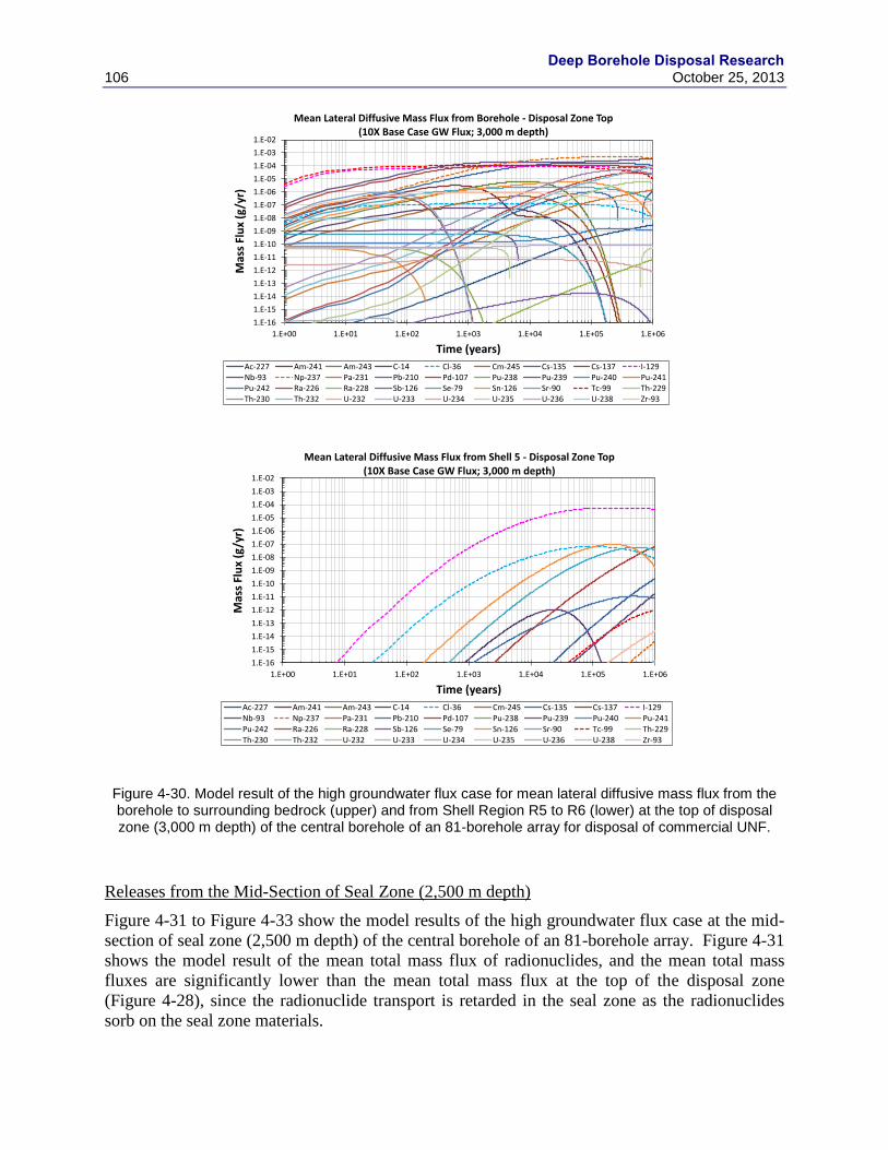
Deep Borehole Disposal Research
106 October 25, 2013
Figure 4-30. Model result of the high groundwater flux case for mean lateral diffusive mass flux from the borehole to surrounding bedrock (upper) and from Shell Region R5 to R6 (lower) at the top of disposal zone (3,000 m depth) of the central borehole of an 81-borehole array for disposal of commercial UNF.
Releases from the Mid-Section of Seal Zone (2,500 m depth)
Figure 4-31 to Figure 4-33 show the model results of the high groundwater flux case at the mid-
section of seal zone (2,500 m depth) of the central borehole of an 81-borehole array. Figure 4-31
shows the model result of the mean total mass flux of radionuclides, and the mean total mass
fluxes are significantly lower than the mean total mass flux at the top of the disposal zone
(Figure 4-28), since the radionuclide transport is retarded in the seal zone as the radionuclides
sorb on the seal zone materials.
1.E-16
1.E-15
1.E-14
1.E-13
1.E-12
1.E-11
1.E-10
1.E-09
1.E-08
1.E-07
1.E-06
1.E-05
1.E-04
1.E-03
1.E-02
1.E+00 1.E+01 1.E+02 1.E+03 1.E+04 1.E+05 1.E+06
Mas
s Fl
ux
(g/y
r)
Time (years)
Mean Lateral Diffusive Mass Flux from Borehole - Disposal Zone Top(10X Base Case GW Flux; 3,000 m depth)
Ac-227 Am-241 Am-243 C-14 Cl-36 Cm-245 Cs-135 Cs-137 I-129Nb-93 Np-237 Pa-231 Pb-210 Pd-107 Pu-238 Pu-239 Pu-240 Pu-241Pu-242 Ra-226 Ra-228 Sb-126 Se-79 Sn-126 Sr-90 Tc-99 Th-229Th-230 Th-232 U-232 U-233 U-234 U-235 U-236 U-238 Zr-93
1.E-16
1.E-15
1.E-14
1.E-13
1.E-12
1.E-11
1.E-10
1.E-09
1.E-08
1.E-07
1.E-06
1.E-05
1.E-04
1.E-03
1.E-02
1.E+00 1.E+01 1.E+02 1.E+03 1.E+04 1.E+05 1.E+06
Mas
s Fl
ux
(g/y
r)
Time (years)
Mean Lateral Diffusive Mass Flux from Shell 5 - Disposal Zone Top(10X Base Case GW Flux; 3,000 m depth)
Ac-227 Am-241 Am-243 C-14 Cl-36 Cm-245 Cs-135 Cs-137 I-129Nb-93 Np-237 Pa-231 Pb-210 Pd-107 Pu-238 Pu-239 Pu-240 Pu-241Pu-242 Ra-226 Ra-228 Sb-126 Se-79 Sn-126 Sr-90 Tc-99 Th-229Th-230 Th-232 U-232 U-233 U-234 U-235 U-236 U-238 Zr-93
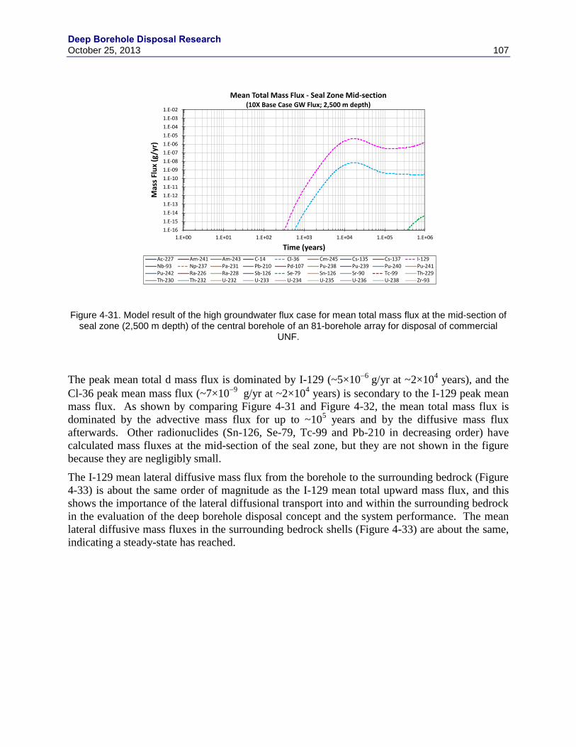
Deep Borehole Disposal Research October 25, 2013 107
Figure 4-31. Model result of the high groundwater flux case for mean total mass flux at the mid-section of seal zone (2,500 m depth) of the central borehole of an 81-borehole array for disposal of commercial
UNF.
The peak mean total d mass flux is dominated by I-129 (~5×10⁶
g/yr at ~2×10⁴ years), and the
Cl-36 peak mean mass flux (~7×10⁹
g/yr at ~2×10⁴ years) is secondary to the I-129 peak mean
mass flux. As shown by comparing Figure 4-31 and Figure 4-32, the mean total mass flux is
dominated by the advective mass flux for up to ~105 years and by the diffusive mass flux
afterwards. Other radionuclides (Sn-126, Se-79, Tc-99 and Pb-210 in decreasing order) have
calculated mass fluxes at the mid-section of the seal zone, but they are not shown in the figure
because they are negligibly small.
The I-129 mean lateral diffusive mass flux from the borehole to the surrounding bedrock (Figure
4-33) is about the same order of magnitude as the I-129 mean total upward mass flux, and this
shows the importance of the lateral diffusional transport into and within the surrounding bedrock
in the evaluation of the deep borehole disposal concept and the system performance. The mean
lateral diffusive mass fluxes in the surrounding bedrock shells (Figure 4-33) are about the same,
indicating a steady-state has reached.
1.E-16
1.E-15
1.E-14
1.E-13
1.E-12
1.E-11
1.E-10
1.E-09
1.E-08
1.E-07
1.E-06
1.E-05
1.E-04
1.E-03
1.E-02
1.E+00 1.E+01 1.E+02 1.E+03 1.E+04 1.E+05 1.E+06
Mas
s Fl
ux
(g/y
r)
Time (years)
Mean Total Mass Flux - Seal Zone Mid-section(10X Base Case GW Flux; 2,500 m depth)
Ac-227 Am-241 Am-243 C-14 Cl-36 Cm-245 Cs-135 Cs-137 I-129Nb-93 Np-237 Pa-231 Pb-210 Pd-107 Pu-238 Pu-239 Pu-240 Pu-241Pu-242 Ra-226 Ra-228 Sb-126 Se-79 Sn-126 Sr-90 Tc-99 Th-229Th-230 Th-232 U-232 U-233 U-234 U-235 U-236 U-238 Zr-93
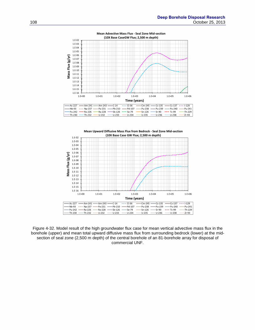
Deep Borehole Disposal Research
108 October 25, 2013
Figure 4-32. Model result of the high groundwater flux case for mean vertical advective mass flux in the borehole (upper) and mean total upward diffusive mass flux from surrounding bedrock (lower) at the mid-
section of seal zone (2,500 m depth) of the central borehole of an 81-borehole array for disposal of commercial UNF.
1.E-16
1.E-15
1.E-14
1.E-13
1.E-12
1.E-11
1.E-10
1.E-09
1.E-08
1.E-07
1.E-06
1.E-05
1.E-04
1.E-03
1.E-02
1.E+00 1.E+01 1.E+02 1.E+03 1.E+04 1.E+05 1.E+06
Mas
s Fl
ux
(g/y
r)
Time (years)
Mean Advective Mass Flux - Seal Zone Mid-section(10X Base CaseGW Flux; 2,500 m depth)
Ac-227 Am-241 Am-243 C-14 Cl-36 Cm-245 Cs-135 Cs-137 I-129Nb-93 Np-237 Pa-231 Pb-210 Pd-107 Pu-238 Pu-239 Pu-240 Pu-241Pu-242 Ra-226 Ra-228 Sb-126 Se-79 Sn-126 Sr-90 Tc-99 Th-229Th-230 Th-232 U-232 U-233 U-234 U-235 U-236 U-238 Zr-93
1.E-16
1.E-15
1.E-14
1.E-13
1.E-12
1.E-11
1.E-10
1.E-09
1.E-08
1.E-07
1.E-06
1.E-05
1.E-04
1.E-03
1.E-02
1.E+00 1.E+01 1.E+02 1.E+03 1.E+04 1.E+05 1.E+06
Mas
s Fl
ux
(g/y
r)
Time (years)
Mean Upward Diffusive Mass Flux from Bedrock - Seal Zone Mid-section(10X Base Case GW Flux; 2,500 m depth)
Ac-227 Am-241 Am-243 C-14 Cl-36 Cm-245 Cs-135 Cs-137 I-129Nb-93 Np-237 Pa-231 Pb-210 Pd-107 Pu-238 Pu-239 Pu-240 Pu-241Pu-242 Ra-226 Ra-228 Sb-126 Se-79 Sn-126 Sr-90 Tc-99 Th-229Th-230 Th-232 U-232 U-233 U-234 U-235 U-236 U-238 Zr-93
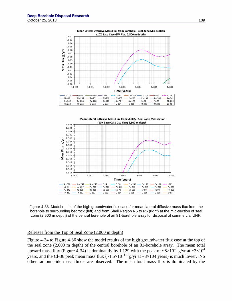
Deep Borehole Disposal Research October 25, 2013 109
Figure 4-33. Model result of the high groundwater flux case for mean lateral diffusive mass flux from the borehole to surrounding bedrock (left) and from Shell Region R5 to R6 (right) at the mid-section of seal zone (2,500 m depth) of the central borehole of an 81-borehole array for disposal of commercial UNF.
Releases from the Top of Seal Zone (2,000 m depth)
Figure 4-34 to Figure 4-36 show the model results of the high groundwater flux case at the top of
the seal zone (2,000 m depth) of the central borehole of an 81-borehole array. The mean total
upward mass flux (Figure 4-34) is dominantly by I-129 with the peak of ~8×10⁹
g/yr at ~3×10⁴
years, and the Cl-36 peak mean mass flux (~1.5×10¹¹
g/yr at ~3×10⁴ years) is much lower. No
other radionuclide mass fluxes are observed. The mean total mass flux is dominated by the
1.E-16
1.E-15
1.E-14
1.E-13
1.E-12
1.E-11
1.E-10
1.E-09
1.E-08
1.E-07
1.E-06
1.E-05
1.E-04
1.E-03
1.E-02
1.E+00 1.E+01 1.E+02 1.E+03 1.E+04 1.E+05 1.E+06
Mas
s Fl
ux
(g/y
r)
Time (years)
Mean Lateral Diffusive Mass Flux from Borehole - Seal Zone Mid-section(10X Base Case GW Flux; 2,500 m depth)
Ac-227 Am-241 Am-243 C-14 Cl-36 Cm-245 Cs-135 Cs-137 I-129Nb-93 Np-237 Pa-231 Pb-210 Pd-107 Pu-238 Pu-239 Pu-240 Pu-241Pu-242 Ra-226 Ra-228 Sb-126 Se-79 Sn-126 Sr-90 Tc-99 Th-229Th-230 Th-232 U-232 U-233 U-234 U-235 U-236 U-238 Zr-93
1.E-16
1.E-15
1.E-14
1.E-13
1.E-12
1.E-11
1.E-10
1.E-09
1.E-08
1.E-07
1.E-06
1.E-05
1.E-04
1.E-03
1.E-02
1.E+00 1.E+01 1.E+02 1.E+03 1.E+04 1.E+05 1.E+06
Mas
s Fl
ux
(g/y
r)
Time (years)
Mean Lateral Diffusive Mass Flux from Shell 5 - Seal Zone Mid-section(10X Base Case GW Flux; 2,500 m depth)
Ac-227 Am-241 Am-243 C-14 Cl-36 Cm-245 Cs-135 Cs-137 I-129Nb-93 Np-237 Pa-231 Pb-210 Pd-107 Pu-238 Pu-239 Pu-240 Pu-241Pu-242 Ra-226 Ra-228 Sb-126 Se-79 Sn-126 Sr-90 Tc-99 Th-229Th-230 Th-232 U-232 U-233 U-234 U-235 U-236 U-238 Zr-93
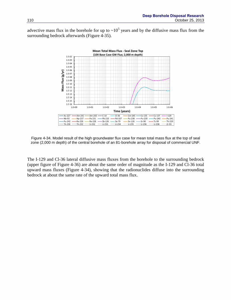
Deep Borehole Disposal Research
110 October 25, 2013
advective mass flux in the borehole for up to ~105 years and by the diffusive mass flux from the
surrounding bedrock afterwards (Figure 4-35).
Figure 4-34. Model result of the high groundwater flux case for mean total mass flux at the top of seal zone (2,000 m depth) of the central borehole of an 81-borehole array for disposal of commercial UNF.
The I-129 and Cl-36 lateral diffusive mass fluxes from the borehole to the surrounding bedrock
(upper figure of Figure 4-36) are about the same order of magnitude as the I-129 and Cl-36 total
upward mass fluxes (Figure 4-34), showing that the radionuclides diffuse into the surrounding
bedrock at about the same rate of the upward total mass flux.
1.E-16
1.E-15
1.E-14
1.E-13
1.E-12
1.E-11
1.E-10
1.E-09
1.E-08
1.E-07
1.E-06
1.E-05
1.E-04
1.E-03
1.E-02
1.E+00 1.E+01 1.E+02 1.E+03 1.E+04 1.E+05 1.E+06
Mas
s Fl
ux
(g/y
r)
Time (years)
Mean Total Mass Flux - Seal Zone Top(10X Base Case GW Flux; 2,000 m depth)
Ac-227 Am-241 Am-243 C-14 Cl-36 Cm-245 Cs-135 Cs-137 I-129Nb-93 Np-237 Pa-231 Pb-210 Pd-107 Pu-238 Pu-239 Pu-240 Pu-241Pu-242 Ra-226 Ra-228 Sb-126 Se-79 Sn-126 Sr-90 Tc-99 Th-229Th-230 Th-232 U-232 U-233 U-234 U-235 U-236 U-238 Zr-93
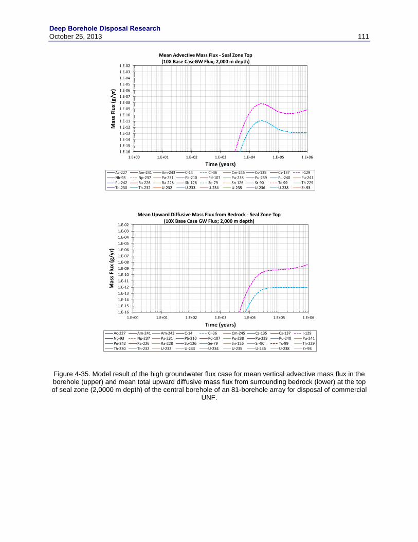
Deep Borehole Disposal Research October 25, 2013 111
Figure 4-35. Model result of the high groundwater flux case for mean vertical advective mass flux in the borehole (upper) and mean total upward diffusive mass flux from surrounding bedrock (lower) at the top of seal zone (2,0000 m depth) of the central borehole of an 81-borehole array for disposal of commercial
UNF.
1.E-16
1.E-15
1.E-14
1.E-13
1.E-12
1.E-11
1.E-10
1.E-09
1.E-08
1.E-07
1.E-06
1.E-05
1.E-04
1.E-03
1.E-02
1.E+00 1.E+01 1.E+02 1.E+03 1.E+04 1.E+05 1.E+06
Mas
s Fl
ux
(g/y
r)
Time (years)
Mean Advective Mass Flux - Seal Zone Top(10X Base CaseGW Flux; 2,000 m depth)
Ac-227 Am-241 Am-243 C-14 Cl-36 Cm-245 Cs-135 Cs-137 I-129Nb-93 Np-237 Pa-231 Pb-210 Pd-107 Pu-238 Pu-239 Pu-240 Pu-241Pu-242 Ra-226 Ra-228 Sb-126 Se-79 Sn-126 Sr-90 Tc-99 Th-229Th-230 Th-232 U-232 U-233 U-234 U-235 U-236 U-238 Zr-93
1.E-16
1.E-15
1.E-14
1.E-13
1.E-12
1.E-11
1.E-10
1.E-09
1.E-08
1.E-07
1.E-06
1.E-05
1.E-04
1.E-03
1.E-02
1.E+00 1.E+01 1.E+02 1.E+03 1.E+04 1.E+05 1.E+06
Mas
s Fl
ux
(g/y
r)
Time (years)
Mean Upward Diffusive Mass Flux from Bedrock - Seal Zone Top(10X Base Case GW Flux; 2,000 m depth)
Ac-227 Am-241 Am-243 C-14 Cl-36 Cm-245 Cs-135 Cs-137 I-129Nb-93 Np-237 Pa-231 Pb-210 Pd-107 Pu-238 Pu-239 Pu-240 Pu-241Pu-242 Ra-226 Ra-228 Sb-126 Se-79 Sn-126 Sr-90 Tc-99 Th-229Th-230 Th-232 U-232 U-233 U-234 U-235 U-236 U-238 Zr-93

Deep Borehole Disposal Research
112 October 25, 2013
Figure 4-36. Model result of the high groundwater flux case for mean lateral diffusive mass flux from the borehole to surrounding bedrock (upper) and from Shell Region R5 to R6 (lower) at the top of seal zone
(2,000 m depth) of the central borehole of an 81-borehole array for disposal of commercial UNF.
Releases from the Mid-section of Upper Zone (1,000 m depth)
Figure 4-37 shows the model result of the mean total mass flux for the high groundwater flux
case at the mid-section of the upper zone (1,000 m depth) of the central borehole of an 81-
borehole array. As shown in the figure, I-129 is the only radionuclide contributing to the mass
release, and the peak mean flux is only ~4×10¹⁴
g/yr at 106 years. The Cl-36 releases are much
smaller and are not shown in the figure.
1.E-16
1.E-15
1.E-14
1.E-13
1.E-12
1.E-11
1.E-10
1.E-09
1.E-08
1.E-07
1.E-06
1.E-05
1.E-04
1.E-03
1.E-02
1.E+00 1.E+01 1.E+02 1.E+03 1.E+04 1.E+05 1.E+06
Mas
s Fl
ux
(g/y
r)
Time (years)
Mean Lateral Diffusive Mass Flux from Borehole - Seal Zone Top(10X Base Case GW Flux; 2,000 m depth)
Ac-227 Am-241 Am-243 C-14 Cl-36 Cm-245 Cs-135 Cs-137 I-129Nb-93 Np-237 Pa-231 Pb-210 Pd-107 Pu-238 Pu-239 Pu-240 Pu-241Pu-242 Ra-226 Ra-228 Sb-126 Se-79 Sn-126 Sr-90 Tc-99 Th-229Th-230 Th-232 U-232 U-233 U-234 U-235 U-236 U-238 Zr-93
1.E-16
1.E-15
1.E-14
1.E-13
1.E-12
1.E-11
1.E-10
1.E-09
1.E-08
1.E-07
1.E-06
1.E-05
1.E-04
1.E-03
1.E-02
1.E+00 1.E+01 1.E+02 1.E+03 1.E+04 1.E+05 1.E+06
Mas
s Fl
ux
(g/y
r)
Time (years)
Mean Lateral Diffusive Mass Flux from Shell 5 - Seal Zone Top(10X Base Case GW Flux; 2,000 m depth)
Ac-227 Am-241 Am-243 C-14 Cl-36 Cm-245 Cs-135 Cs-137 I-129Nb-93 Np-237 Pa-231 Pb-210 Pd-107 Pu-238 Pu-239 Pu-240 Pu-241Pu-242 Ra-226 Ra-228 Sb-126 Se-79 Sn-126 Sr-90 Tc-99 Th-229Th-230 Th-232 U-232 U-233 U-234 U-235 U-236 U-238 Zr-93

Deep Borehole Disposal Research October 25, 2013 113
The I-129 mean total upward mass flux is composed about equally of the advective flux in the
borehole and the upward diffusive mass flux from the surrounding bedrock for up to ~6×10⁴
years, and dominated by the diffusive flux afterwards. The I-129 mean lateral diffusive mass
flux from the borehole to the surrounding bedrock is about the same order of magnitude as the I-
129 mean total upward mass flux from the surrounding bedrock.
Figure 4-37. Model result of the high groundwater flux case for mean total mass flux at the mid-section of upper zone (1,000 m depth) of the central borehole of an 81-borehole array for disposal of commercial
UNF.
Releases at the top of Upper Zone
Figure 4-38 shows the model result of the mean total mass flux of the high groundwater flux case
at the top of upper zone of the central borehole of an 81-borehole array. Only I-129 and Cl-36
have calculated mass releases, and their mass fluxes are negligibly small: ~5×10²²
g/yr at 106
years for I-129 and ~1×1025
g/yr at 106 years for Cl-36. The radionuclide fluxes are dominated
by the upward diffusive mass flux from the surrounding bedrock (not shown).
Figure 4-39 shows the model result of the mean annual dose of RNs reaching the biosphere. As
discussed in the beginning of Section 4.4.2, the IAEA ERB1B dose model (IAEA 2003) was
used to calculate the dose. The calculated annual dose is negligibly small with the peak mean
annual dose of ~5x10²¹
mrem/yr at 106 years due to I-129.
1.E-16
1.E-15
1.E-14
1.E-13
1.E-12
1.E-11
1.E-10
1.E-09
1.E-08
1.E-07
1.E-06
1.E-05
1.E-04
1.E-03
1.E-02
1.E+00 1.E+01 1.E+02 1.E+03 1.E+04 1.E+05 1.E+06
Mas
s Fl
ux
(g/y
r)
Time (years)
Mean Total Mass Flux - Upper Zone Mid-section(10X Base Case GW Flux; 1,000 m depth)
Ac-227 Am-241 Am-243 C-14 Cl-36 Cm-245 Cs-135 Cs-137 I-129Nb-93 Np-237 Pa-231 Pb-210 Pd-107 Pu-238 Pu-239 Pu-240 Pu-241Pu-242 Ra-226 Ra-228 Sb-126 Se-79 Sn-126 Sr-90 Tc-99 Th-229Th-230 Th-232 U-232 U-233 U-234 U-235 U-236 U-238 Zr-93
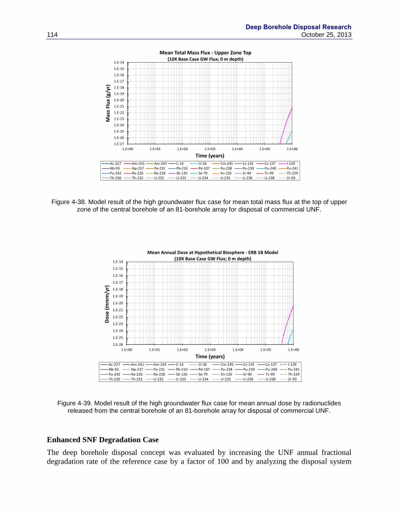
Deep Borehole Disposal Research
114 October 25, 2013
Figure 4-38. Model result of the high groundwater flux case for mean total mass flux at the top of upper zone of the central borehole of an 81-borehole array for disposal of commercial UNF.
Figure 4-39. Model result of the high groundwater flux case for mean annual dose by radionuclides released from the central borehole of an 81-borehole array for disposal of commercial UNF.
Enhanced SNF Degradation Case
The deep borehole disposal concept was evaluated by increasing the UNF annual fractional
degradation rate of the reference case by a factor of 100 and by analyzing the disposal system
1.E-27
1.E-26
1.E-25
1.E-24
1.E-23
1.E-22
1.E-21
1.E-20
1.E-19
1.E-18
1.E-17
1.E-16
1.E-15
1.E-14
1.E+00 1.E+01 1.E+02 1.E+03 1.E+04 1.E+05 1.E+06
Mas
s Fl
ux
(g/y
r)
Time (years)
Mean Total Mass Flux - Upper Zone Top(10X Base Case GW Flux; 0 m depth)
Ac-227 Am-241 Am-243 C-14 Cl-36 Cm-245 Cs-135 Cs-137 I-129Nb-93 Np-237 Pa-231 Pb-210 Pd-107 Pu-238 Pu-239 Pu-240 Pu-241Pu-242 Ra-226 Ra-228 Sb-126 Se-79 Sn-126 Sr-90 Tc-99 Th-229Th-230 Th-232 U-232 U-233 U-234 U-235 U-236 U-238 Zr-93
1.E-26
1.E-25
1.E-24
1.E-23
1.E-22
1.E-21
1.E-20
1.E-19
1.E-18
1.E-17
1.E-16
1.E-15
1.E-14
1.E+00 1.E+01 1.E+02 1.E+03 1.E+04 1.E+05 1.E+06
Do
se (
mre
m/y
r)
Time (years)
Mean Annual Dose at Hypothetical Biosphere - ERB 1B Model(10X Base Case GW Flux; 0 m depth)
Ac-227 Am-241 Am-243 C-14 Cl-36 Cm-245 Cs-135 Cs-137 I-129Nb-93 Np-237 Pa-231 Pb-210 Pd-107 Pu-238 Pu-239 Pu-240 Pu-241Pu-242 Ra-226 Ra-228 Sb-126 Se-79 Sn-126 Sr-90 Tc-99 Th-229Th-230 Th-232 U-232 U-233 U-234 U-235 U-236 U-238 Zr-93
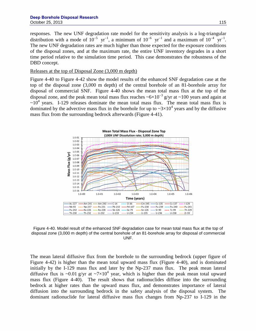
Deep Borehole Disposal Research October 25, 2013 115
responses. The new UNF degradation rate model for the sensitivity analysis is a log-triangular
distribution with a mode of 105
yr1
, a minimum of 106
yr1
and a maximum of 104
yr1
.
The new UNF degradation rates are much higher than those expected for the exposure conditions
of the disposal zones, and at the maximum rate, the entire UNF inventory degrades in a short
time period relative to the simulation time period. This case demonstrates the robustness of the
DBD concept.
Releases at the top of Disposal Zone (3,000 m depth)
Figure 4-40 to Figure 4-42 show the model results of the enhanced SNF degradation case at the
top of the disposal zone (3,000 m depth) of the central borehole of an 81-borehole array for
disposal of commercial SNF. Figure 4-40 shows the mean total mass flux at the top of the
disposal zone, and the peak mean total mass flux reaches ~6×10³
g/yr at ~100 years and again at
~104 years. I-129 releases dominate the mean total mass flux. The mean total mass flux is
dominated by the advective mass flux in the borehole for up to ~3×10⁴ years and by the diffusive
mass flux from the surrounding bedrock afterwards (Figure 4-41).
Figure 4-40. Model result of the enhanced SNF degradation case for mean total mass flux at the top of disposal zone (3,000 m depth) of the central borehole of an 81-borehole array for disposal of commercial
UNF.
The mean lateral diffusive flux from the borehole to the surrounding bedrock (upper figure of
Figure 4-42) is higher than the mean total upward mass flux (Figure 4-40), and is dominated
initially by the I-129 mass flux and later by the Np-237 mass flux. The peak mean lateral
diffusive flux is ~0.01 g/yr at ~7×10⁴ year, which is higher than the peak mean total upward
mass flux (Figure 4-40). The result shows that radionuclides diffuse into the surrounding
bedrock at higher rates than the upward mass flux, and demonstrates importance of lateral
diffusion into the surrounding bedrock in the safety analysis of the disposal system. The
dominant radionuclide for lateral diffusive mass flux changes from Np-237 to I-129 in the
1.E-16
1.E-15
1.E-14
1.E-13
1.E-12
1.E-11
1.E-10
1.E-09
1.E-08
1.E-07
1.E-06
1.E-05
1.E-04
1.E-03
1.E-02
1.E-01
1.E+00 1.E+01 1.E+02 1.E+03 1.E+04 1.E+05 1.E+06
Mas
s Fl
ux
(g/y
r)
Time (years)
Mean Total Mass Flux - Disposal Zone Top(100X UNF Dissolution rate; 3,000 m depth)
Ac-227 Am-241 Am-243 C-14 Cl-36 Cm-245 Cs-135 Cs-137 I-129Nb-93 Np-237 Pa-231 Pb-210 Pd-107 Pu-238 Pu-239 Pu-240 Pu-241Pu-242 Ra-226 Ra-228 Sb-126 Se-79 Sn-126 Sr-90 Tc-99 Th-229Th-230 Th-232 U-232 U-233 U-234 U-235 U-236 U-238 Zr-93
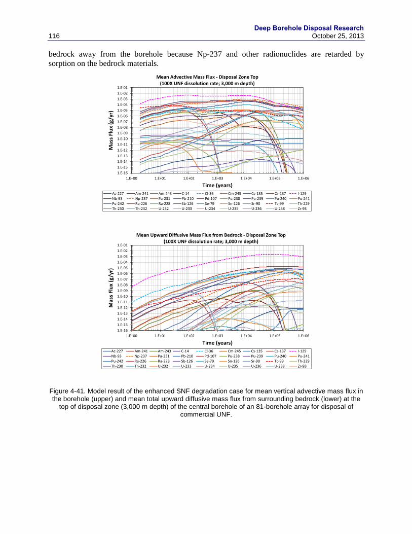
Deep Borehole Disposal Research
116 October 25, 2013
bedrock away from the borehole because Np-237 and other radionuclides are retarded by
sorption on the bedrock materials.
Figure 4-41. Model result of the enhanced SNF degradation case for mean vertical advective mass flux in the borehole (upper) and mean total upward diffusive mass flux from surrounding bedrock (lower) at the
top of disposal zone (3,000 m depth) of the central borehole of an 81-borehole array for disposal of commercial UNF.
1.E-16
1.E-15
1.E-14
1.E-13
1.E-12
1.E-11
1.E-10
1.E-09
1.E-08
1.E-07
1.E-06
1.E-05
1.E-04
1.E-03
1.E-02
1.E-01
1.E+00 1.E+01 1.E+02 1.E+03 1.E+04 1.E+05 1.E+06
Mas
s Fl
ux
(g/y
r)
Time (years)
Mean Advective Mass Flux - Disposal Zone Top(100X UNF dissolution rate; 3,000 m depth)
Ac-227 Am-241 Am-243 C-14 Cl-36 Cm-245 Cs-135 Cs-137 I-129Nb-93 Np-237 Pa-231 Pb-210 Pd-107 Pu-238 Pu-239 Pu-240 Pu-241Pu-242 Ra-226 Ra-228 Sb-126 Se-79 Sn-126 Sr-90 Tc-99 Th-229Th-230 Th-232 U-232 U-233 U-234 U-235 U-236 U-238 Zr-93
1.E-16
1.E-15
1.E-14
1.E-13
1.E-12
1.E-11
1.E-10
1.E-09
1.E-08
1.E-07
1.E-06
1.E-05
1.E-04
1.E-03
1.E-02
1.E-01
1.E+00 1.E+01 1.E+02 1.E+03 1.E+04 1.E+05 1.E+06
Mas
s Fl
ux
(g/y
r)
Time (years)
Mean Upward Diffusive Mass Flux from Bedrock - Disposal Zone Top(100X UNF dissolution rate; 3,000 m depth)
Ac-227 Am-241 Am-243 C-14 Cl-36 Cm-245 Cs-135 Cs-137 I-129Nb-93 Np-237 Pa-231 Pb-210 Pd-107 Pu-238 Pu-239 Pu-240 Pu-241Pu-242 Ra-226 Ra-228 Sb-126 Se-79 Sn-126 Sr-90 Tc-99 Th-229Th-230 Th-232 U-232 U-233 U-234 U-235 U-236 U-238 Zr-93
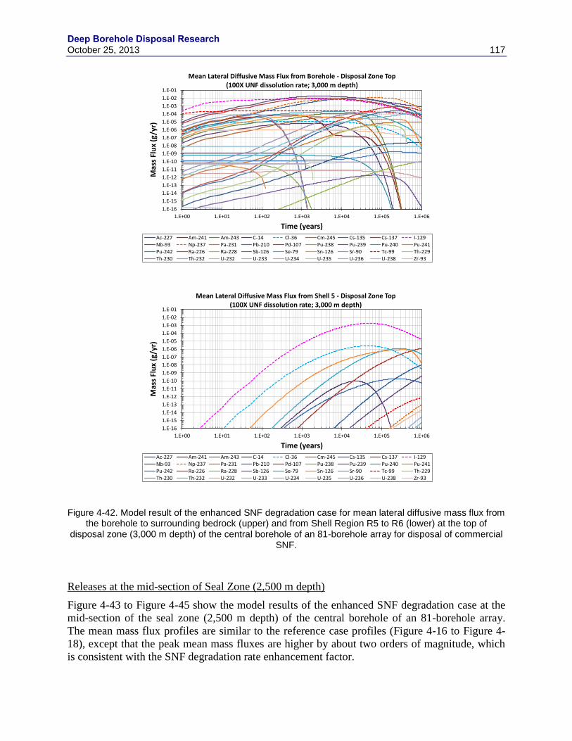
Deep Borehole Disposal Research October 25, 2013 117
Figure 4-42. Model result of the enhanced SNF degradation case for mean lateral diffusive mass flux from the borehole to surrounding bedrock (upper) and from Shell Region R5 to R6 (lower) at the top of
disposal zone (3,000 m depth) of the central borehole of an 81-borehole array for disposal of commercial SNF.
Releases at the mid-section of Seal Zone (2,500 m depth)
Figure 4-43 to Figure 4-45 show the model results of the enhanced SNF degradation case at the
mid-section of the seal zone (2,500 m depth) of the central borehole of an 81-borehole array.
The mean mass flux profiles are similar to the reference case profiles (Figure 4-16 to Figure 4-
18), except that the peak mean mass fluxes are higher by about two orders of magnitude, which
is consistent with the SNF degradation rate enhancement factor.
1.E-16
1.E-15
1.E-14
1.E-13
1.E-12
1.E-11
1.E-10
1.E-09
1.E-08
1.E-07
1.E-06
1.E-05
1.E-04
1.E-03
1.E-02
1.E-01
1.E+00 1.E+01 1.E+02 1.E+03 1.E+04 1.E+05 1.E+06
Mas
s Fl
ux
(g/y
r)
Time (years)
Mean Lateral Diffusive Mass Flux from Borehole - Disposal Zone Top(100X UNF dissolution rate; 3,000 m depth)
Ac-227 Am-241 Am-243 C-14 Cl-36 Cm-245 Cs-135 Cs-137 I-129Nb-93 Np-237 Pa-231 Pb-210 Pd-107 Pu-238 Pu-239 Pu-240 Pu-241Pu-242 Ra-226 Ra-228 Sb-126 Se-79 Sn-126 Sr-90 Tc-99 Th-229Th-230 Th-232 U-232 U-233 U-234 U-235 U-236 U-238 Zr-93
1.E-16
1.E-15
1.E-14
1.E-13
1.E-12
1.E-11
1.E-10
1.E-09
1.E-08
1.E-07
1.E-06
1.E-05
1.E-04
1.E-03
1.E-02
1.E-01
1.E+00 1.E+01 1.E+02 1.E+03 1.E+04 1.E+05 1.E+06
Mas
s Fl
ux
(g/y
r)
Time (years)
Mean Lateral Diffusive Mass Flux from Shell 5 - Disposal Zone Top(100X UNF dissolution rate; 3,000 m depth)
Ac-227 Am-241 Am-243 C-14 Cl-36 Cm-245 Cs-135 Cs-137 I-129Nb-93 Np-237 Pa-231 Pb-210 Pd-107 Pu-238 Pu-239 Pu-240 Pu-241Pu-242 Ra-226 Ra-228 Sb-126 Se-79 Sn-126 Sr-90 Tc-99 Th-229Th-230 Th-232 U-232 U-233 U-234 U-235 U-236 U-238 Zr-93
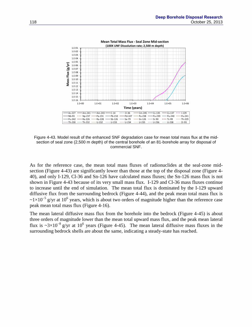
Deep Borehole Disposal Research
118 October 25, 2013
Figure 4-43. Model result of the enhanced SNF degradation case for mean total mass flux at the mid-section of seal zone (2,500 m depth) of the central borehole of an 81-borehole array for disposal of
commercial SNF.
As for the reference case, the mean total mass fluxes of radionuclides at the seal-zone mid-
section (Figure 4-43) are significantly lower than those at the top of the disposal zone (Figure 4-
40), and only I-129, Cl-36 and Sn-126 have calculated mass fluxes; the Sn-126 mass flux is not
shown in Figure 4-43 because of its very small mass flux. I-129 and Cl-36 mass fluxes continue
to increase until the end of simulation. The mean total flux is dominated by the I-129 upward
diffusive flux from the surrounding bedrock (Figure 4-44), and the peak mean total mass flux is
~1×10⁵
g/yr at 106 years, which is about two orders of magnitude higher than the reference case
peak mean total mass flux (Figure 4-16).
The mean lateral diffusive mass flux from the borehole into the bedrock (Figure 4-45) is about
three orders of magnitude lower than the mean total upward mass flux, and the peak mean lateral
flux is ~3×10⁸
g/yr at 106 years (Figure 4-45). The mean lateral diffusive mass fluxes in the
surrounding bedrock shells are about the same, indicating a steady-state has reached.
1.E-16
1.E-15
1.E-14
1.E-13
1.E-12
1.E-11
1.E-10
1.E-09
1.E-08
1.E-07
1.E-06
1.E-05
1.E-04
1.E-03
1.E-02
1.E-01
1.E+00 1.E+01 1.E+02 1.E+03 1.E+04 1.E+05 1.E+06
Mas
s Fl
ux
(g/y
r)
Time (years)
Mean Total Mass Flux - Seal Zone Mid-section(100X UNF Dissolution rate; 2,500 m depth)
Ac-227 Am-241 Am-243 C-14 Cl-36 Cm-245 Cs-135 Cs-137 I-129Nb-93 Np-237 Pa-231 Pb-210 Pd-107 Pu-238 Pu-239 Pu-240 Pu-241Pu-242 Ra-226 Ra-228 Sb-126 Se-79 Sn-126 Sr-90 Tc-99 Th-229Th-230 Th-232 U-232 U-233 U-234 U-235 U-236 U-238 Zr-93
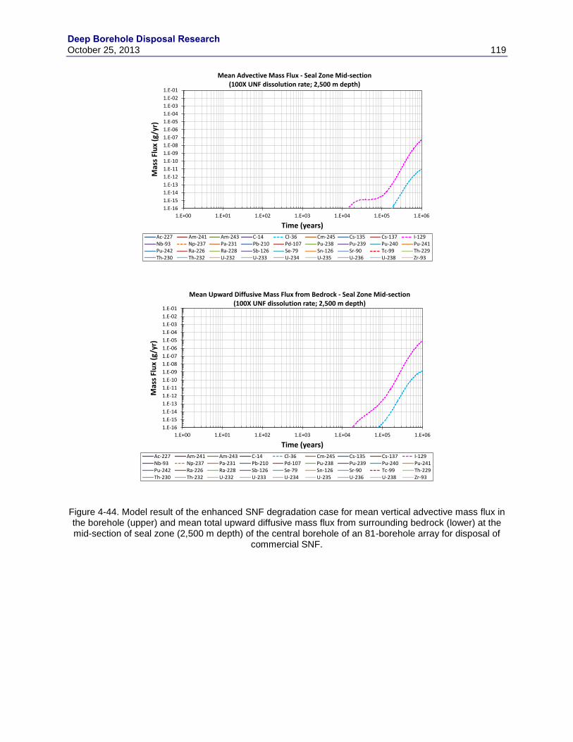
Deep Borehole Disposal Research October 25, 2013 119
Figure 4-44. Model result of the enhanced SNF degradation case for mean vertical advective mass flux in the borehole (upper) and mean total upward diffusive mass flux from surrounding bedrock (lower) at the mid-section of seal zone (2,500 m depth) of the central borehole of an 81-borehole array for disposal of
commercial SNF.
1.E-16
1.E-15
1.E-14
1.E-13
1.E-12
1.E-11
1.E-10
1.E-09
1.E-08
1.E-07
1.E-06
1.E-05
1.E-04
1.E-03
1.E-02
1.E-01
1.E+00 1.E+01 1.E+02 1.E+03 1.E+04 1.E+05 1.E+06
Mas
s Fl
ux
(g/y
r)
Time (years)
Mean Advective Mass Flux - Seal Zone Mid-section(100X UNF dissolution rate; 2,500 m depth)
Ac-227 Am-241 Am-243 C-14 Cl-36 Cm-245 Cs-135 Cs-137 I-129Nb-93 Np-237 Pa-231 Pb-210 Pd-107 Pu-238 Pu-239 Pu-240 Pu-241Pu-242 Ra-226 Ra-228 Sb-126 Se-79 Sn-126 Sr-90 Tc-99 Th-229Th-230 Th-232 U-232 U-233 U-234 U-235 U-236 U-238 Zr-93
1.E-16
1.E-15
1.E-14
1.E-13
1.E-12
1.E-11
1.E-10
1.E-09
1.E-08
1.E-07
1.E-06
1.E-05
1.E-04
1.E-03
1.E-02
1.E-01
1.E+00 1.E+01 1.E+02 1.E+03 1.E+04 1.E+05 1.E+06
Mas
s Fl
ux
(g/y
r)
Time (years)
Mean Upward Diffusive Mass Flux from Bedrock - Seal Zone Mid-section(100X UNF dissolution rate; 2,500 m depth)
Ac-227 Am-241 Am-243 C-14 Cl-36 Cm-245 Cs-135 Cs-137 I-129Nb-93 Np-237 Pa-231 Pb-210 Pd-107 Pu-238 Pu-239 Pu-240 Pu-241Pu-242 Ra-226 Ra-228 Sb-126 Se-79 Sn-126 Sr-90 Tc-99 Th-229Th-230 Th-232 U-232 U-233 U-234 U-235 U-236 U-238 Zr-93
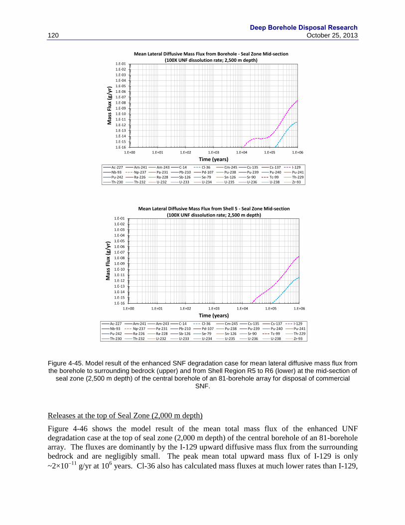
Deep Borehole Disposal Research
120 October 25, 2013
Figure 4-45. Model result of the enhanced SNF degradation case for mean lateral diffusive mass flux from the borehole to surrounding bedrock (upper) and from Shell Region R5 to R6 (lower) at the mid-section of
seal zone (2,500 m depth) of the central borehole of an 81-borehole array for disposal of commercial SNF.
Releases at the top of Seal Zone (2,000 m depth)
Figure 4-46 shows the model result of the mean total mass flux of the enhanced UNF
degradation case at the top of seal zone (2,000 m depth) of the central borehole of an 81-borehole
array. The fluxes are dominantly by the I-129 upward diffusive mass flux from the surrounding
bedrock and are negligibly small. The peak mean total upward mass flux of I-129 is only
~2×10¹¹
g/yr at 106 years. Cl-36 also has calculated mass fluxes at much lower rates than I-129,
1.E-16
1.E-15
1.E-14
1.E-13
1.E-12
1.E-11
1.E-10
1.E-09
1.E-08
1.E-07
1.E-06
1.E-05
1.E-04
1.E-03
1.E-02
1.E-01
1.E+00 1.E+01 1.E+02 1.E+03 1.E+04 1.E+05 1.E+06
Mas
s Fl
ux
(g/y
r)
Time (years)
Mean Lateral Diffusive Mass Flux from Borehole - Seal Zone Mid-section(100X UNF dissolution rate; 2,500 m depth)
Ac-227 Am-241 Am-243 C-14 Cl-36 Cm-245 Cs-135 Cs-137 I-129Nb-93 Np-237 Pa-231 Pb-210 Pd-107 Pu-238 Pu-239 Pu-240 Pu-241Pu-242 Ra-226 Ra-228 Sb-126 Se-79 Sn-126 Sr-90 Tc-99 Th-229Th-230 Th-232 U-232 U-233 U-234 U-235 U-236 U-238 Zr-93
1.E-16
1.E-15
1.E-14
1.E-13
1.E-12
1.E-11
1.E-10
1.E-09
1.E-08
1.E-07
1.E-06
1.E-05
1.E-04
1.E-03
1.E-02
1.E-01
1.E+00 1.E+01 1.E+02 1.E+03 1.E+04 1.E+05 1.E+06
Mas
s Fl
ux
(g/y
r)
Time (years)
Mean Lateral Diffusive Mass Flux from Shell 5 - Seal Zone Mid-section(100X UNF dissolution rate; 2,500 m depth)
Ac-227 Am-241 Am-243 C-14 Cl-36 Cm-245 Cs-135 Cs-137 I-129Nb-93 Np-237 Pa-231 Pb-210 Pd-107 Pu-238 Pu-239 Pu-240 Pu-241Pu-242 Ra-226 Ra-228 Sb-126 Se-79 Sn-126 Sr-90 Tc-99 Th-229Th-230 Th-232 U-232 U-233 U-234 U-235 U-236 U-238 Zr-93
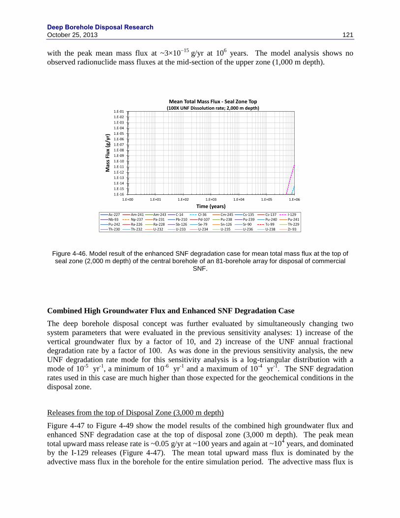
Deep Borehole Disposal Research October 25, 2013 121
with the peak mean mass flux at ~3×10¹⁵
g/yr at 106 years. The model analysis shows no
observed radionuclide mass fluxes at the mid-section of the upper zone (1,000 m depth).
Figure 4-46. Model result of the enhanced SNF degradation case for mean total mass flux at the top of seal zone (2,000 m depth) of the central borehole of an 81-borehole array for disposal of commercial
SNF.
Combined High Groundwater Flux and Enhanced SNF Degradation Case
The deep borehole disposal concept was further evaluated by simultaneously changing two
system parameters that were evaluated in the previous sensitivity analyses: 1) increase of the
vertical groundwater flux by a factor of 10, and 2) increase of the UNF annual fractional
degradation rate by a factor of 100. As was done in the previous sensitivity analysis, the new
UNF degradation rate mode for this sensitivity analysis is a log-triangular distribution with a
mode of 10-5
yr-1
, a minimum of 10-6
yr-1
and a maximum of 10-4
yr-1
. The SNF degradation
rates used in this case are much higher than those expected for the geochemical conditions in the
disposal zone.
Releases from the top of Disposal Zone (3,000 m depth)
Figure 4-47 to Figure 4-49 show the model results of the combined high groundwater flux and
enhanced SNF degradation case at the top of disposal zone (3,000 m depth). The peak mean
total upward mass release rate is ~0.05 g/yr at ~100 years and again at ~104 years, and dominated
by the I-129 releases (Figure 4-47). The mean total upward mass flux is dominated by the
advective mass flux in the borehole for the entire simulation period. The advective mass flux is
1.E-16
1.E-15
1.E-14
1.E-13
1.E-12
1.E-11
1.E-10
1.E-09
1.E-08
1.E-07
1.E-06
1.E-05
1.E-04
1.E-03
1.E-02
1.E-01
1.E+00 1.E+01 1.E+02 1.E+03 1.E+04 1.E+05 1.E+06
Mas
s Fl
ux
(g/y
r)
Time (years)
Mean Total Mass Flux - Seal Zone Top(100X UNF Dissolution rate; 2,000 m depth)
Ac-227 Am-241 Am-243 C-14 Cl-36 Cm-245 Cs-135 Cs-137 I-129Nb-93 Np-237 Pa-231 Pb-210 Pd-107 Pu-238 Pu-239 Pu-240 Pu-241Pu-242 Ra-226 Ra-228 Sb-126 Se-79 Sn-126 Sr-90 Tc-99 Th-229Th-230 Th-232 U-232 U-233 U-234 U-235 U-236 U-238 Zr-93
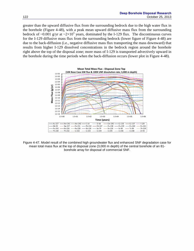
Deep Borehole Disposal Research
122 October 25, 2013
greater than the upward diffusive flux from the surrounding bedrock due to the high water flux in
the borehole (Figure 4-48), with a peak mean upward diffusive mass flux from the surrounding
bedrock of ~0.001 g/yr at ~2×10⁵ years, dominated by the I-129 flux. The discontinuous curves
for the I-129 diffusive mass flux from the surrounding bedrock (lower figure of Figure 4-48) are
due to the back-diffusion (i.e., negative diffusive mass flux transporting the mass downward) that
results from higher I-129 dissolved concentrations in the bedrock region around the borehole
right above the top of the disposal zone; more mass of I-129 is transported advectively upward in
the borehole during the time periods when the back-diffusion occurs (lower plot in Figure 4-48).
Figure 4-47. Model result of the combined high groundwater flux and enhanced SNF degradation case for mean total mass flux at the top of disposal zone (3,000 m depth) of the central borehole of an 81-
borehole array for disposal of commercial SNF.
1.E-16
1.E-15
1.E-14
1.E-13
1.E-12
1.E-11
1.E-10
1.E-09
1.E-08
1.E-07
1.E-06
1.E-05
1.E-04
1.E-03
1.E-02
1.E-01
1.E+00 1.E+01 1.E+02 1.E+03 1.E+04 1.E+05 1.E+06
Mas
s Fl
ux
(g/y
r)
Time (years)
Mean Total Mass Flux - Disposal Zone Top(10X Base Case GW flux & 100X UNF dissolution rate; 3,000 m depth)
Ac-227 Am-241 Am-243 C-14 Cl-36 Cm-245 Cs-135 Cs-137 I-129Nb-93 Np-237 Pa-231 Pb-210 Pd-107 Pu-238 Pu-239 Pu-240 Pu-241Pu-242 Ra-226 Ra-228 Sb-126 Se-79 Sn-126 Sr-90 Tc-99 Th-229Th-230 Th-232 U-232 U-233 U-234 U-235 U-236 U-238 Zr-93

Deep Borehole Disposal Research October 25, 2013 123
Figure 4-48. Model result of the combined high groundwater flux and enhanced SNF degradation case for mean vertical advective mass flux in the borehole (upper) and mean total upward diffusive mass flux from surrounding bedrock (lower) at the top of disposal zone (3,000 m depth) of the central borehole of an 81-
borehole array for disposal of commercial SNF.
1.E-16
1.E-15
1.E-14
1.E-13
1.E-12
1.E-11
1.E-10
1.E-09
1.E-08
1.E-07
1.E-06
1.E-05
1.E-04
1.E-03
1.E-02
1.E-01
1.E+00 1.E+01 1.E+02 1.E+03 1.E+04 1.E+05 1.E+06
Mas
s Fl
ux
(g/y
r)
Time (years)
Mean Advective Mass Flux - Disposal Zone Top(10X Base Case GW flux & 100X UNF dissolution rate; 3,000 m depth)
Ac-227 Am-241 Am-243 C-14 Cl-36 Cm-245 Cs-135 Cs-137 I-129Nb-93 Np-237 Pa-231 Pb-210 Pd-107 Pu-238 Pu-239 Pu-240 Pu-241Pu-242 Ra-226 Ra-228 Sb-126 Se-79 Sn-126 Sr-90 Tc-99 Th-229Th-230 Th-232 U-232 U-233 U-234 U-235 U-236 U-238 Zr-93
1.E-16
1.E-15
1.E-14
1.E-13
1.E-12
1.E-11
1.E-10
1.E-09
1.E-08
1.E-07
1.E-06
1.E-05
1.E-04
1.E-03
1.E-02
1.E-01
1.E+00 1.E+01 1.E+02 1.E+03 1.E+04 1.E+05 1.E+06
Mas
s Fl
ux
(g/y
r)
Time (years)
Mean Upward Diffusive Mass Flux from Bedrock - Disposal Zone Top(10X Base Case GW flux & 100X UNF dissolution rate; 3,000 m depth)
Ac-227 Am-241 Am-243 C-14 Cl-36 Cm-245 Cs-135 Cs-137 I-129Nb-93 Np-237 Pa-231 Pb-210 Pd-107 Pu-238 Pu-239 Pu-240 Pu-241Pu-242 Ra-226 Ra-228 Sb-126 Se-79 Sn-126 Sr-90 Tc-99 Th-229Th-230 Th-232 U-232 U-233 U-234 U-235 U-236 U-238 Zr-93

Deep Borehole Disposal Research
124 October 25, 2013
Figure 4-49. Model result of the combined high groundwater flux and enhanced SNF degradation case for mean lateral diffusive mass flux from the borehole to surrounding bedrock (upper) and from Shell Region
R5 to R6 (lower) at the top of disposal zone (3,000 m depth) of the central borehole of an 81-borehole array for disposal of commercial SNF.
The mean lateral diffusive mass flux from the borehole to the surrounding bedrock (upper figure
of Figure 4-49) is about the same order of magnitude as the mean total upward mass flux (figure
4-47), and this demonstrates the importance of lateral diffusional transport into and within the
surrounding bedrock to the safety analysis of the deep borehole disposal system.
The mean lateral diffusive mass flux from the borehole to the surrounding bedrock is dominated
initially by I-129 and later by Np-237 (upper figure of Figure 4-49), and the peak mean lateral
1.E-16
1.E-15
1.E-14
1.E-13
1.E-12
1.E-11
1.E-10
1.E-09
1.E-08
1.E-07
1.E-06
1.E-05
1.E-04
1.E-03
1.E-02
1.E-01
1.E+00 1.E+01 1.E+02 1.E+03 1.E+04 1.E+05 1.E+06
Mas
s Fl
ux
(g/y
r)
Time (years)
Mean Lateral Diffusive Mass Flux from Borehole - Disposal Zone Top(10X Base Case GW flux & 100X UNF dissolution rate; 3,000 m depth)
Ac-227 Am-241 Am-243 C-14 Cl-36 Cm-245 Cs-135 Cs-137 I-129Nb-93 Np-237 Pa-231 Pb-210 Pd-107 Pu-238 Pu-239 Pu-240 Pu-241Pu-242 Ra-226 Ra-228 Sb-126 Se-79 Sn-126 Sr-90 Tc-99 Th-229Th-230 Th-232 U-232 U-233 U-234 U-235 U-236 U-238 Zr-93
1.E-16
1.E-15
1.E-14
1.E-13
1.E-12
1.E-11
1.E-10
1.E-09
1.E-08
1.E-07
1.E-06
1.E-05
1.E-04
1.E-03
1.E-02
1.E-01
1.E+00 1.E+01 1.E+02 1.E+03 1.E+04 1.E+05 1.E+06
Mas
s Fl
ux
(g/y
r)
Time (years)
Mean Lateral Diffusive Mass Flux from Shell 5 - Disposal Zone Top(10X Base Case GW flux & 100X UNF dissolution rate; 3,000 m depth)
Ac-227 Am-241 Am-243 C-14 Cl-36 Cm-245 Cs-135 Cs-137 I-129Nb-93 Np-237 Pa-231 Pb-210 Pd-107 Pu-238 Pu-239 Pu-240 Pu-241Pu-242 Ra-226 Ra-228 Sb-126 Se-79 Sn-126 Sr-90 Tc-99 Th-229Th-230 Th-232 U-232 U-233 U-234 U-235 U-236 U-238 Zr-93

Deep Borehole Disposal Research October 25, 2013 125
diffusive mass flux is ~0.01 g/yr at ~105 years, mainly due to Np-237. There is an earlier peak
mean lateral mass flux attributable to Nb-93 (~0.02 g/yr at ~2,000 years) but this radionuclide is
not radioactive and does not contribute to dose. Note again that the discontinuous lateral
diffusive mass flux curves of some RNs (upper figure of Figure 4-49) are due to the back-
diffusion from the bedrock region right next to the borehole (Shell Region R2, Table 4-12). The
mean lateral diffusive flux in outer bedrock shells is dominated by I-129, since other
radionuclides are retarded by sorption on the bedrock materials. Figure 4-49 (lower figure)
shows the mean diffusive mass flux from Shell Region R5 (second to the last shell; see Table 4-
12).
Releases from the mid-section of Seal Zone (2,500 m depth)
Figure 4-50 to Figure 4-52 show the model results of the combined high groundwater flux and
enhanced SNF degradation case at the mid-section of seal zone (2,500 m depth) of the central
borehole of an 81-borehole array. The mean total upward mass fluxes are significantly lower
than the mean total mass flux at the top of the disposal zone (Figure 4-50), since most
radionuclides (except I-129 and Cl-36) are retarded in the seal zone as they sorb on the seal zone
materials. The peak mean total mass flux is dominated by I-129 (~4×10⁴
g/yr at ~2×10⁴ years),
and the Cl-36 peak mean mass flux (~5×10⁷
g/yr at ~2×10⁴ years) is secondary to the I-129
peak mean mass flux.
Figure 4-50. Model result of the combined high groundwater flux and enhanced SNF degradation case for mean total mass flux at the mid-section of seal zone (2,500 m depth) of the central borehole of an 81-
borehole array for disposal of commercial SNF.
1.E-16
1.E-15
1.E-14
1.E-13
1.E-12
1.E-11
1.E-10
1.E-09
1.E-08
1.E-07
1.E-06
1.E-05
1.E-04
1.E-03
1.E-02
1.E-01
1.E+00 1.E+01 1.E+02 1.E+03 1.E+04 1.E+05 1.E+06
Mas
s Fl
ux
(g/y
r)
Time (years)
Mean Total Mass Flux - Seal Zone Mid-section(10X Base Case GW flux & 100X UNF dissolution rate; 2,500 m depth)
Ac-227 Am-241 Am-243 C-14 Cl-36 Cm-245 Cs-135 Cs-137 I-129Nb-93 Np-237 Pa-231 Pb-210 Pd-107 Pu-238 Pu-239 Pu-240 Pu-241Pu-242 Ra-226 Ra-228 Sb-126 Se-79 Sn-126 Sr-90 Tc-99 Th-229Th-230 Th-232 U-232 U-233 U-234 U-235 U-236 U-238 Zr-93

Deep Borehole Disposal Research
126 October 25, 2013
Figure 4-51. Model result of the combined high groundwater flux and enhanced SNF degradation case for mean vertical advective mass flux in the borehole (upper) and mean total upward diffusive mass flux from surrounding bedrock (lower) at the mid-section of seal zone (2,5000 m depth) of the central borehole of
an 81-borehole array for disposal of commercial SNF.
1.E-16
1.E-15
1.E-14
1.E-13
1.E-12
1.E-11
1.E-10
1.E-09
1.E-08
1.E-07
1.E-06
1.E-05
1.E-04
1.E-03
1.E-02
1.E-01
1.E+00 1.E+01 1.E+02 1.E+03 1.E+04 1.E+05 1.E+06
Mas
s Fl
ux
(g/y
r)
Time (years)
Mean Advective Mass Flux - Seal Zone Mid-section(10X Base Case GW flux & 100X UNF dissolution rate; 2,500 m depth)
Ac-227 Am-241 Am-243 C-14 Cl-36 Cm-245 Cs-135 Cs-137 I-129Nb-93 Np-237 Pa-231 Pb-210 Pd-107 Pu-238 Pu-239 Pu-240 Pu-241Pu-242 Ra-226 Ra-228 Sb-126 Se-79 Sn-126 Sr-90 Tc-99 Th-229Th-230 Th-232 U-232 U-233 U-234 U-235 U-236 U-238 Zr-93
1.E-16
1.E-15
1.E-14
1.E-13
1.E-12
1.E-11
1.E-10
1.E-09
1.E-08
1.E-07
1.E-06
1.E-05
1.E-04
1.E-03
1.E-02
1.E-01
1.E+00 1.E+01 1.E+02 1.E+03 1.E+04 1.E+05 1.E+06
Mas
s Fl
ux
(g/y
r)
Time (years)
Mean Upward Diffusive Mass Flux from Bedrock - Seal Zone Mid-section(10X Base Case GW flux & 100X UNF dissolution rate; 2,500 m depth)
Ac-227 Am-241 Am-243 C-14 Cl-36 Cm-245 Cs-135 Cs-137 I-129Nb-93 Np-237 Pa-231 Pb-210 Pd-107 Pu-238 Pu-239 Pu-240 Pu-241Pu-242 Ra-226 Ra-228 Sb-126 Se-79 Sn-126 Sr-90 Tc-99 Th-229Th-230 Th-232 U-232 U-233 U-234 U-235 U-236 U-238 Zr-93
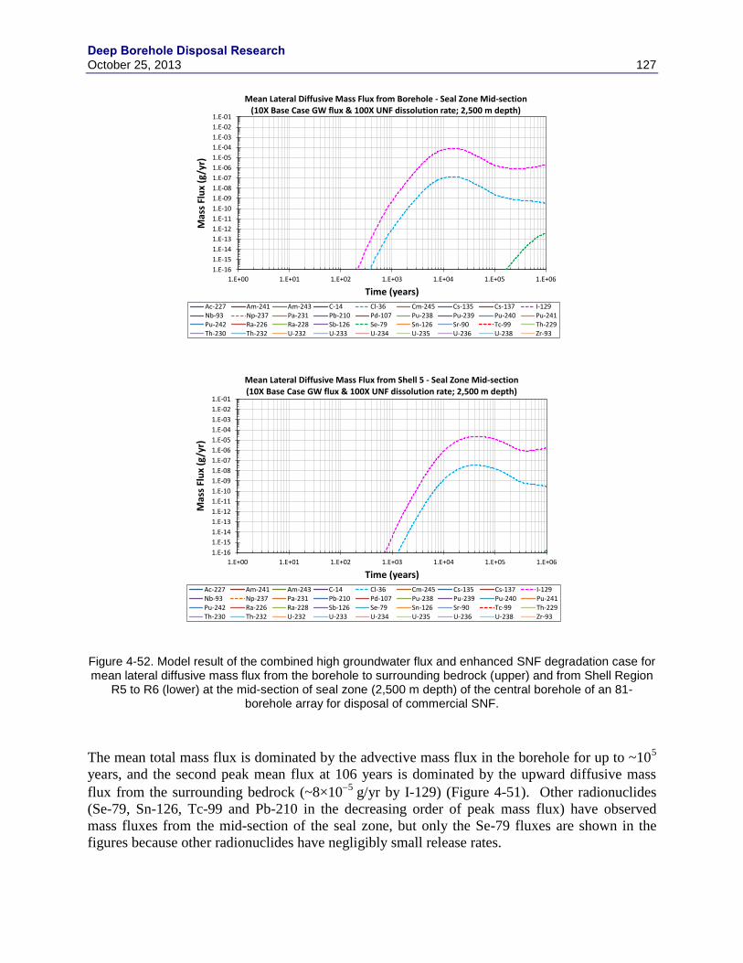
Deep Borehole Disposal Research October 25, 2013 127
Figure 4-52. Model result of the combined high groundwater flux and enhanced SNF degradation case for mean lateral diffusive mass flux from the borehole to surrounding bedrock (upper) and from Shell Region
R5 to R6 (lower) at the mid-section of seal zone (2,500 m depth) of the central borehole of an 81-borehole array for disposal of commercial SNF.
The mean total mass flux is dominated by the advective mass flux in the borehole for up to ~105
years, and the second peak mean flux at 106 years is dominated by the upward diffusive mass
flux from the surrounding bedrock (~8×10⁵
g/yr by I-129) (Figure 4-51). Other radionuclides
(Se-79, Sn-126, Tc-99 and Pb-210 in the decreasing order of peak mass flux) have observed
mass fluxes from the mid-section of the seal zone, but only the Se-79 fluxes are shown in the
figures because other radionuclides have negligibly small release rates.
1.E-16
1.E-15
1.E-14
1.E-13
1.E-12
1.E-11
1.E-10
1.E-09
1.E-08
1.E-07
1.E-06
1.E-05
1.E-04
1.E-03
1.E-02
1.E-01
1.E+00 1.E+01 1.E+02 1.E+03 1.E+04 1.E+05 1.E+06
Mas
s Fl
ux
(g/y
r)
Time (years)
Mean Lateral Diffusive Mass Flux from Borehole - Seal Zone Mid-section(10X Base Case GW flux & 100X UNF dissolution rate; 2,500 m depth)
Ac-227 Am-241 Am-243 C-14 Cl-36 Cm-245 Cs-135 Cs-137 I-129Nb-93 Np-237 Pa-231 Pb-210 Pd-107 Pu-238 Pu-239 Pu-240 Pu-241Pu-242 Ra-226 Ra-228 Sb-126 Se-79 Sn-126 Sr-90 Tc-99 Th-229Th-230 Th-232 U-232 U-233 U-234 U-235 U-236 U-238 Zr-93
1.E-16
1.E-15
1.E-14
1.E-13
1.E-12
1.E-11
1.E-10
1.E-09
1.E-08
1.E-07
1.E-06
1.E-05
1.E-04
1.E-03
1.E-02
1.E-01
1.E+00 1.E+01 1.E+02 1.E+03 1.E+04 1.E+05 1.E+06
Mas
s Fl
ux
(g/y
r)
Time (years)
Mean Lateral Diffusive Mass Flux from Shell 5 - Seal Zone Mid-section(10X Base Case GW flux & 100X UNF dissolution rate; 2,500 m depth)
Ac-227 Am-241 Am-243 C-14 Cl-36 Cm-245 Cs-135 Cs-137 I-129Nb-93 Np-237 Pa-231 Pb-210 Pd-107 Pu-238 Pu-239 Pu-240 Pu-241Pu-242 Ra-226 Ra-228 Sb-126 Se-79 Sn-126 Sr-90 Tc-99 Th-229Th-230 Th-232 U-232 U-233 U-234 U-235 U-236 U-238 Zr-93
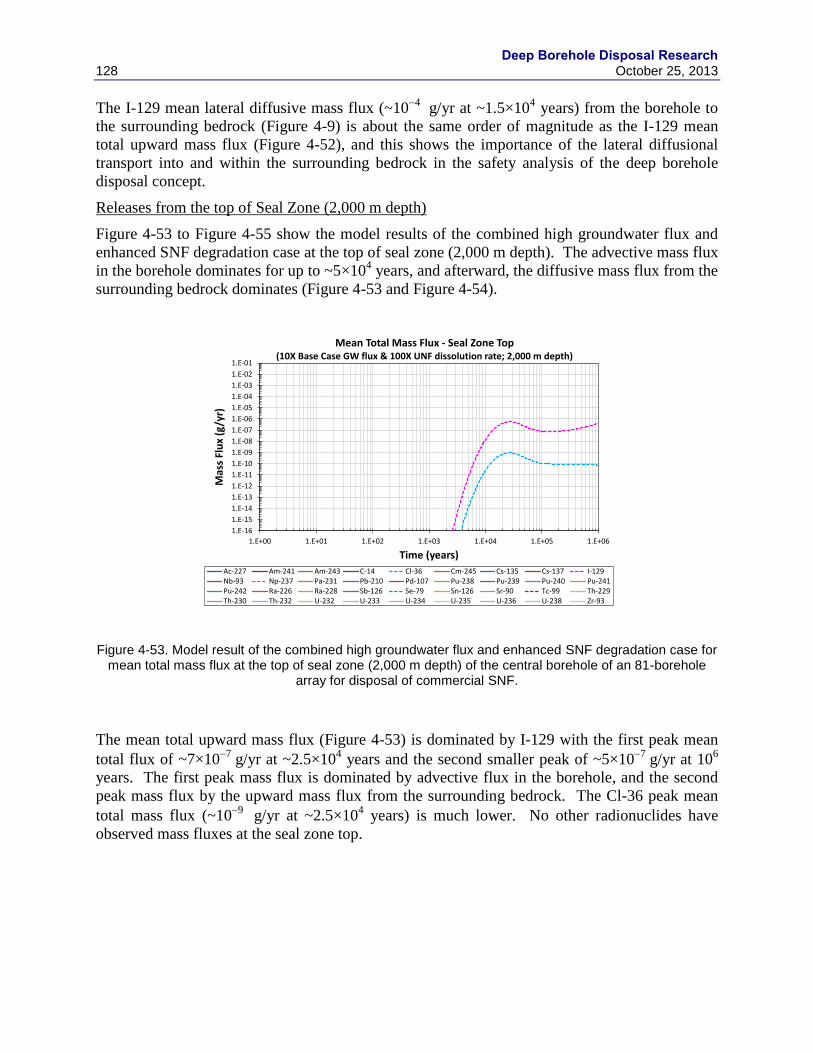
Deep Borehole Disposal Research
128 October 25, 2013
The I-129 mean lateral diffusive mass flux (~104
g/yr at ~1.5×10⁴ years) from the borehole to
the surrounding bedrock (Figure 4-9) is about the same order of magnitude as the I-129 mean
total upward mass flux (Figure 4-52), and this shows the importance of the lateral diffusional
transport into and within the surrounding bedrock in the safety analysis of the deep borehole
disposal concept.
Releases from the top of Seal Zone (2,000 m depth)
Figure 4-53 to Figure 4-55 show the model results of the combined high groundwater flux and
enhanced SNF degradation case at the top of seal zone (2,000 m depth). The advective mass flux
in the borehole dominates for up to ~5×10⁴ years, and afterward, the diffusive mass flux from the
surrounding bedrock dominates (Figure 4-53 and Figure 4-54).
Figure 4-53. Model result of the combined high groundwater flux and enhanced SNF degradation case for mean total mass flux at the top of seal zone (2,000 m depth) of the central borehole of an 81-borehole
array for disposal of commercial SNF.
The mean total upward mass flux (Figure 4-53) is dominated by I-129 with the first peak mean
total flux of ~7×10⁷
g/yr at ~2.5×10⁴ years and the second smaller peak of ~5×10
7 g/yr at 10
6
years. The first peak mass flux is dominated by advective flux in the borehole, and the second
peak mass flux by the upward mass flux from the surrounding bedrock. The Cl-36 peak mean
total mass flux (~109
g/yr at ~2.5×10⁴ years) is much lower. No other radionuclides have
observed mass fluxes at the seal zone top.
1.E-16
1.E-15
1.E-14
1.E-13
1.E-12
1.E-11
1.E-10
1.E-09
1.E-08
1.E-07
1.E-06
1.E-05
1.E-04
1.E-03
1.E-02
1.E-01
1.E+00 1.E+01 1.E+02 1.E+03 1.E+04 1.E+05 1.E+06
Mas
s Fl
ux
(g/y
r)
Time (years)
Mean Total Mass Flux - Seal Zone Top(10X Base Case GW flux & 100X UNF dissolution rate; 2,000 m depth)
Ac-227 Am-241 Am-243 C-14 Cl-36 Cm-245 Cs-135 Cs-137 I-129Nb-93 Np-237 Pa-231 Pb-210 Pd-107 Pu-238 Pu-239 Pu-240 Pu-241Pu-242 Ra-226 Ra-228 Sb-126 Se-79 Sn-126 Sr-90 Tc-99 Th-229Th-230 Th-232 U-232 U-233 U-234 U-235 U-236 U-238 Zr-93
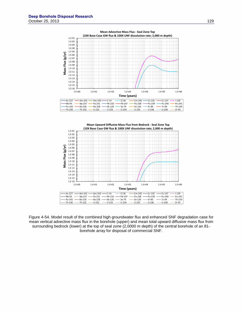
Deep Borehole Disposal Research October 25, 2013 129
Figure 4-54. Model result of the combined high groundwater flux and enhanced SNF degradation case for mean vertical advective mass flux in the borehole (upper) and mean total upward diffusive mass flux from
surrounding bedrock (lower) at the top of seal zone (2,0000 m depth) of the central borehole of an 81-borehole array for disposal of commercial SNF.
1.E-16
1.E-15
1.E-14
1.E-13
1.E-12
1.E-11
1.E-10
1.E-09
1.E-08
1.E-07
1.E-06
1.E-05
1.E-04
1.E-03
1.E-02
1.E-01
1.E+00 1.E+01 1.E+02 1.E+03 1.E+04 1.E+05 1.E+06
Mas
s Fl
ux
(g/y
r)
Time (years)
Mean Advective Mass Flux - Seal Zone Top(10X Base Case GW flux & 100X UNF dissolution rate; 2,000 m depth)
Ac-227 Am-241 Am-243 C-14 Cl-36 Cm-245 Cs-135 Cs-137 I-129Nb-93 Np-237 Pa-231 Pb-210 Pd-107 Pu-238 Pu-239 Pu-240 Pu-241Pu-242 Ra-226 Ra-228 Sb-126 Se-79 Sn-126 Sr-90 Tc-99 Th-229Th-230 Th-232 U-232 U-233 U-234 U-235 U-236 U-238 Zr-93
1.E-16
1.E-15
1.E-14
1.E-13
1.E-12
1.E-11
1.E-10
1.E-09
1.E-08
1.E-07
1.E-06
1.E-05
1.E-04
1.E-03
1.E-02
1.E-01
1.E+00 1.E+01 1.E+02 1.E+03 1.E+04 1.E+05 1.E+06
Mas
s Fl
ux
(g/y
r)
Time (years)
Mean Upward Diffusive Mass Flux from Bedrock - Seal Zone Top(10X Base Case GW flux & 100X UNF dissolution rate; 2,000 m depth)
Ac-227 Am-241 Am-243 C-14 Cl-36 Cm-245 Cs-135 Cs-137 I-129Nb-93 Np-237 Pa-231 Pb-210 Pd-107 Pu-238 Pu-239 Pu-240 Pu-241Pu-242 Ra-226 Ra-228 Sb-126 Se-79 Sn-126 Sr-90 Tc-99 Th-229Th-230 Th-232 U-232 U-233 U-234 U-235 U-236 U-238 Zr-93
Deep Borehole Disposal Research
130 October 25, 2013
Figure 4-55. Model result of the combined high groundwater flux and enhanced SNF degradation case for mean lateral diffusive mass flux from the borehole to surrounding bedrock (upper) and from Shell Region R5 to R6 (lower) at the top of seal zone (2,000 m depth) of the central borehole of an 81-borehole array
for disposal of commercial SNF.
The I-129 and Cl-36 lateral diffusive mass fluxes from the borehole to the surrounding bedrock
(upper figure of Figure 4-55) are about the same order of magnitude as the I-129 and Cl-36 total
upward mass fluxes (Figure 4-53), showing that the radionuclides diffuse into the surrounding
bedrock at about the same rate of the upward total mass flux. The peak lateral diffusive flux
from the borehole is ~2×10⁷
g/yr at ~2.5×10⁴ years by I-129.
1.E-16
1.E-15
1.E-14
1.E-13
1.E-12
1.E-11
1.E-10
1.E-09
1.E-08
1.E-07
1.E-06
1.E-05
1.E-04
1.E-03
1.E-02
1.E-01
1.E+00 1.E+01 1.E+02 1.E+03 1.E+04 1.E+05 1.E+06
Mas
s Fl
ux
(g/y
r)
Time (years)
Mean Lateral Diffusive Mass Flux from Borehole - Seal Zone Top(10X Base Case GW flux & 100X UNF dissolution rate; 2,000 m depth)
Ac-227 Am-241 Am-243 C-14 Cl-36 Cm-245 Cs-135 Cs-137 I-129Nb-93 Np-237 Pa-231 Pb-210 Pd-107 Pu-238 Pu-239 Pu-240 Pu-241Pu-242 Ra-226 Ra-228 Sb-126 Se-79 Sn-126 Sr-90 Tc-99 Th-229Th-230 Th-232 U-232 U-233 U-234 U-235 U-236 U-238 Zr-93
1.E-16
1.E-15
1.E-14
1.E-13
1.E-12
1.E-11
1.E-10
1.E-09
1.E-08
1.E-07
1.E-06
1.E-05
1.E-04
1.E-03
1.E-02
1.E-01
1.E+00 1.E+01 1.E+02 1.E+03 1.E+04 1.E+05 1.E+06
Mas
s Fl
ux
(g/y
r)
Time (years)
Mean Lateral Diffusive Mass Flux from Shell 5 - Seal Zone Top(10X Base Case GW flux & 100X UNF dissolution rate; 2,000 m depth)
Ac-227 Am-241 Am-243 C-14 Cl-36 Cm-245 Cs-135 Cs-137 I-129Nb-93 Np-237 Pa-231 Pb-210 Pd-107 Pu-238 Pu-239 Pu-240 Pu-241Pu-242 Ra-226 Ra-228 Sb-126 Se-79 Sn-126 Sr-90 Tc-99 Th-229Th-230 Th-232 U-232 U-233 U-234 U-235 U-236 U-238 Zr-93

Deep Borehole Disposal Research October 25, 2013 131
Releases from the mid-section of Upper Zone (1,000 m depth)
Figure 4-56 and Figure 4-57 show the model results at the mid-section of upper zone (1,000 m
depth). Figure 4-56 shows the mean total upward mass flux, and I-129 is the dominant
radionuclide contributing to the mean total mass fluxes. The peak mean total mass flux is
~4×10¹²
g/yr at 106 years for I-129. The mean total releases (i.e., I-129 releases) are dominated
by the upward diffusive mass flux from the surrounding bedrock (Figure 4-57). The Cl-36
releases are much smaller with the peak mean mass flux of ~2×10¹⁵
g/yr at ~5.5×10⁴ years. The
peak mean lateral diffusive mass flux from the borehole to the surrounding bedrock
(~8×10¹³
g/yr for I-129) is about the same order of magnitude as the peak mean total upward
mass flux (figure not shown).
Figure 4-56. Model result of the combined high groundwater flux and enhanced SNF degradation case for mean total mass flux at the mid-section of upper zone (1,000 m depth) of the central borehole of an 81-
borehole array for disposal of commercial UNF.
Releases from the top of Upper Zone
Figure 4-58 shows the model result of the mean total upward mass flux of the combined high
groundwater flux and enhanced SNF degradation case at the top of upper zone of the central
borehole of an 81-borehole array. Only I-129 and Cl-36 have observed mass fluxes, but they are
negligibly small. The peak mean total mass flux for I-129 is ~5×10²⁰
g/yr at 106 years, and the
peak rate for Cl-36 is ~1×10²³
g/yr at 106 years. The radionuclide mass fluxes are dominated
by the upward diffusive mass flux from the surrounding bedrock (not shown).
1.E-16
1.E-15
1.E-14
1.E-13
1.E-12
1.E-11
1.E-10
1.E-09
1.E-08
1.E-07
1.E-06
1.E-05
1.E-04
1.E-03
1.E-02
1.E-01
1.E+00 1.E+01 1.E+02 1.E+03 1.E+04 1.E+05 1.E+06
Mas
s Fl
ux
(g/y
r)
Time (years)
Mean Total Mass Flux - Upper Zone Mid-section(10X Base Case GW flux & 100X UNF dissolution rate; 1,000 m depth)
Ac-227 Am-241 Am-243 C-14 Cl-36 Cm-245 Cs-135 Cs-137 I-129Nb-93 Np-237 Pa-231 Pb-210 Pd-107 Pu-238 Pu-239 Pu-240 Pu-241Pu-242 Ra-226 Ra-228 Sb-126 Se-79 Sn-126 Sr-90 Tc-99 Th-229Th-230 Th-232 U-232 U-233 U-234 U-235 U-236 U-238 Zr-93
Deep Borehole Disposal Research
132 October 25, 2013
Figure 4-57. Model result of the combined high groundwater flux and enhanced SNF degradation case for mean vertical advective mass flux in the borehole (upper) and mean total upward diffusive mass flux from surrounding bedrock (lower) at the mid-section of upper zone (1,000 m depth) of the central borehole of
an 81-borehole array for disposal of commercial SNF.
Figure 4-59 shows the model result of the mean annual dose by radionuclides for this sensitivity
case. The IAEA ERB1B dose model (IAEA 2003) was used to calculate the dose. The
calculated annual dose is negligibly small with the peak mean annual dose of ~4x10¹⁹
mrem/yr
at 106 years for I-129.
1.E-16
1.E-15
1.E-14
1.E-13
1.E-12
1.E-11
1.E-10
1.E-09
1.E-08
1.E-07
1.E-06
1.E-05
1.E-04
1.E-03
1.E-02
1.E-01
1.E+00 1.E+01 1.E+02 1.E+03 1.E+04 1.E+05 1.E+06
Mas
s Fl
ux
(g/y
r)
Time (years)
Mean Advective Mass Flux - Upper Zone Mid-section(10X Base Case GW flux & 100X UNF dissolution rate; 1,000 m depth)
Ac-227 Am-241 Am-243 C-14 Cl-36 Cm-245 Cs-135 Cs-137 I-129Nb-93 Np-237 Pa-231 Pb-210 Pd-107 Pu-238 Pu-239 Pu-240 Pu-241Pu-242 Ra-226 Ra-228 Sb-126 Se-79 Sn-126 Sr-90 Tc-99 Th-229Th-230 Th-232 U-232 U-233 U-234 U-235 U-236 U-238 Zr-93
1.E-16
1.E-15
1.E-14
1.E-13
1.E-12
1.E-11
1.E-10
1.E-09
1.E-08
1.E-07
1.E-06
1.E-05
1.E-04
1.E-03
1.E-02
1.E-01
1.E+00 1.E+01 1.E+02 1.E+03 1.E+04 1.E+05 1.E+06
Mas
s Fl
ux
(g/y
r)
Time (years)
Mean Upward Diffusive Mass Flux from Bedrock - Upper Zone Mid-section(10X Base Case GW flux & 100X UNF dissolution rate; 1,000 m depth)
Ac-227 Am-241 Am-243 C-14 Cl-36 Cm-245 Cs-135 Cs-137 I-129Nb-93 Np-237 Pa-231 Pb-210 Pd-107 Pu-238 Pu-239 Pu-240 Pu-241Pu-242 Ra-226 Ra-228 Sb-126 Se-79 Sn-126 Sr-90 Tc-99 Th-229Th-230 Th-232 U-232 U-233 U-234 U-235 U-236 U-238 Zr-93
Deep Borehole Disposal Research October 25, 2013 133
Figure 4-58. Model result of the combined high groundwater flux and enhanced SNF degradation case for mean total mass flux at the top of upper zone of the central borehole of an 81-borehole array for disposal
of commercial SNF.
Figure 4-59. Model result of the combined high groundwater flux and enhanced SNF degradation case for mean annual dose by radionuclides released from the central borehole of an 81-borehole array for
disposal of commercial SNF.
1.E-27
1.E-26
1.E-25
1.E-24
1.E-23
1.E-22
1.E-21
1.E-20
1.E-19
1.E-18
1.E-17
1.E-16
1.E-15
1.E-14
1.E+00 1.E+01 1.E+02 1.E+03 1.E+04 1.E+05 1.E+06
Mas
s Fl
ux
(g/y
r)
Time (years)
Mean Total Mass Flux - Upper Zone Top(10X Base Case GW flux & 100X UNF dissolution rate; 0 m depth)
Ac-227 Am-241 Am-243 C-14 Cl-36 Cm-245 Cs-135 Cs-137 I-129Nb-93 Np-237 Pa-231 Pb-210 Pd-107 Pu-238 Pu-239 Pu-240 Pu-241Pu-242 Ra-226 Ra-228 Sb-126 Se-79 Sn-126 Sr-90 Tc-99 Th-229Th-230 Th-232 U-232 U-233 U-234 U-235 U-236 U-238 Zr-93
1.E-27
1.E-26
1.E-25
1.E-24
1.E-23
1.E-22
1.E-21
1.E-20
1.E-19
1.E-18
1.E-17
1.E-16
1.E-15
1.E-14
1.E+00 1.E+01 1.E+02 1.E+03 1.E+04 1.E+05 1.E+06
Do
se (
mre
m/y
r)
Time (years)
Mean Annual Dose at Hypothetical Biosphere - ERB 1B Dose Model(10X Base Case GW flux & 100X UNF dissolution rate; 0 m depth)
Ac-227 Am-241 Am-243 C-14 Cl-36 Cm-245 Cs-135 Cs-137 I-129Nb-93 Np-237 Pa-231 Pb-210 Pd-107 Pu-238 Pu-239 Pu-240 Pu-241Pu-242 Ra-226 Ra-228 Sb-126 Se-79 Sn-126 Sr-90 Tc-99 Th-229Th-230 Th-232 U-232 U-233 U-234 U-235 U-236 U-238 Zr-93

Deep Borehole Disposal Research
134 October 25, 2013
4.4.3 Summary and Discussion
The PA analysis with the updated PA model demonstrates significant lateral diffusion of
radionuclides from the borehole into the surrounding bedrock and diffusional transport within the
bedrock. This process makes the deep borehole disposal system more resilient and less sensitive
to changes of the system parameters tested in the PA analysis. The surrounding bedrock
functions as a large storage or buffer for transport of radionuclides, and most radionuclides
(except I-129 and Cl-36) that have diffused into the surrounding bedrock are sorbed onto the
bedrock materials, which strongly delay their transport.
In the disposal zone, lateral diffusive flux from the borehole into the surrounding bedrock is
greater than the upward mass flux. In the seal zone and the upper zone (if radionuclide mass has
reached the seal zone), lateral mass flux from the borehole into the surrounding bedrock is about
the same order of magnitude as the upward mass flux. This demonstrates the importance of the
diffusional mass transport into the surrounding bedrock for the system performance and safety
analysis. This process, generally not considered for a safety case analysis for a mined geologic
repository, is unique and important to the deep borehole disposal concept, and provides an
additional safety attribute for the deep borehole disposal concept.
For the current deep borehole conceptual design, the PA analysis has shown that high water
fluxes in the borehole are required to move more than a negligible amount of radionuclide mass
to the surface. Upward diffusive mass flux alone is not enough to transport radionuclide mass to
the surface environment to have a meaningful impact on the biosphere dose.
Based on the current PA analysis, it appears that the seals and plugs for the seal zone and upper
zone are important, but they do not seem “critical” to the system performance. The upward
radionuclide diffusive mass flux from the surrounding bedrock is greater than the advective flux
in the borehole. The total upward mass flux in the seal and upper zones is dominated by the
upward diffusive flux from the surrounding bedrock, rather than the upward advective flux in the
borehole.
The current PA analysis provides an important insight that a more detailed representation of
groundwater flow in surrounding bedrock, especially fracture flow, if it occurs, needs to be
included in the safety analysis in order to better represent advective transport in the surrounding
bedrock; only diffusive transport is modeled in the surrounding bedrock in the current PA
analysis.
The rather coarse grid resolution for lateral diffusion (i.e., 6 cylindrical shells for a 100 m
distance) implemented in the updated PA model could have overestimated the diffusive flux into
the bedrock. Nevertheless, the analysis indicates the important contribution to system
performance likely attributable to lateral diffusion, which is unique to the DBD concept. The
impact of lateral diffusion should be evaluated with a finer grid resolution (or greater number of
concentric shells).
4.5 Summary Safety Case for Deep Borehole Disposal
This section introduces an initial study conducted for a generic safety case of the deep borehole
disposal of high-level nuclear waste. Details of this study are documented in Appendix A of this

Deep Borehole Disposal Research October 25, 2013 135
report. The primary objective of this study is to investigate the feasibility of developing a
generic safety case for disposal of commercial spent nuclear fuel, and potentially other
specialized radioactive waste forms in the lower reaches (3-5 km) of deep boreholes drilled into
crystalline basement rock. A safety case is an integrated collection of evidence, analyses, and
other qualitative and quantitative arguments used to demonstrate the safety of a disposal concept.
A generic safety case has much of the same basic structure and objectives as an actual safety
case, but it is not site specific and its primary purpose is to provide the necessary structure for
organizing and synthesizing existing deep borehole science and identifying RD&D activities that
should be carried out in a full-scale demonstration of the concept.
In this study, the major elements of the safety case are patterned after the NEA post-closure
safety case (NEA 2004) and also include aspects of pre-closure safety as follows (see Appendix
A of this report for additional detail):
Statement of Purpose. Describes the current status of the deep borehole disposal concept
program
Safety Strategy. This is the high-level approach adopted for achieving confirmation that
deep borehole disposal is safe.
Site Characterization and Disposal System Design. This contains key portions of the
assessment basis that is described in some safety case concepts (NEA 2004).
Pre-closure and Post-closure Safety Evaluation. This includes a quantitative safety
assessment of potential radiological consequences associated with a range of possible
evolutions of the system over time.
Statement of Confidence and Synthesis of Evidence. The statement of confidence is based
on a synthesis of safety arguments and analyses.
The safety case outlined in this study starts with the recent design concept for a deep borehole
repository developed by Arnold et al. (2011a). The primary components of the reference design
include:
Boreholes
Borehole casing system
Waste canisters
Surface handling and shielding system
Waste emplacement system
Borehole sealing and abandonment
Operational safety assurance and monitoring
The pre-closure safety evaluation involves a systematic examination of the site, the design, and
the potential initiating events caused by underlying hazards (e.g., DOE 2008). An initiating
event is a departure from normal operation that triggers an event sequence. A pre-closure safety
analysis will consist of internal and external initiating event identification, event sequence
analysis, radiological dose and consequence analysis, and criticality analysis. In the case of deep
borehole disposal, the analysis will be supported by drilling safety data from the petroleum
Deep Borehole Disposal Research
136 October 25, 2013
industry, and waste packaging, handling, and emplacement data from radioactive waste disposal
programs and demonstration projects.
The post-closure safety evaluation addresses the ability of a site and repository facility to meet
safety standards and to provide for the safety functions of the engineered and/or geological
components. A complete safety or performance assessment includes quantification of the long-
term, post-closure performance of the repository, analysis of the associated uncertainties in the
prediction of performance, and comparison with the relevant design requirements and safety
standards. Initial performance assessments are summarized in this report in Sections 4.3 and 4.4.
A key consideration in the assessment of post-closure safety is the identification and analysis of
uncertainties that have the potential to significantly impact the understanding of the degree of
safety the system offers. Sensitivity analyses from the post-closure safety assessment will
provide the basis for defining the types of tests and studies needed to reduce uncertainty and for
assigning priorities for further R&D work.
A deep borehole research and demonstration project would build additional confidence in the
areas that could be better examined at a large scale, such as aspects of drilling operations,
borehole stability, canister emplacement and retrieval, operational efficiency, sealing
effectiveness, and safety. Examining coupled physical and chemical processes at a field scale
would help reduce residual uncertainty in these processes.
Focused research activities at the field scale must be “risk-informed” in a systematic fashion by
the current version of the generic safety case and any associated performance assessment
analyses, such as uncertainty and sensitivity analyses, which generate valuable information to
determine the parameters and processes that most affect repository performance. It is important
that a technical management and assessment structure be put in place prior to any testing at a
demonstration project site. Such a structure would first consider the overall testing needs and
preferred arrangements of the site consistent with the safety case.
Finally, one important and necessary aspect of each element of the generic safety case is quality
assurance (QA). All elements of a deep borehole demonstration must be properly planned,
implemented, and documented, such that the technical basis for confirming the safety of the
concept is repeatable, transparent, and traceable. These requirements are applicable to site
characterization, general collection of data for PA, PA software and models, expert judgment
activities, borehole drilling and construction, and pre-closure and post-closure demonstration
activities.
Deep Borehole Disposal Research October 25, 2013 137
5. DEMONSTRATION PROJECT PLANNING
5.1 Deep Borehole Disposal Consortium
The Deep Borehole Disposal Consortium was established through the course of two meetings in
Albuquerque, New Mexico in 2011 and 2013 and consists of industrial and academic partners
that were assembled to enhance efforts to complete a deep borehole demonstration. Members
include Areva, CH2M-Hill, DOSECC Exploration Services, Massachusetts Institute of
Technology, Olympic Research, Sandia National Laboratories, University of Sheffield, and
URS. In August, 2013 a Memorandum of Understanding (MOU) was signed to enable
collaboration between the parties to “promote the construction and operation of a deep borehole
demonstration to evaluate the feasibility of long-term disposal of nuclear waste”. The MOU
establishes a legal mechanism for consortium members to collaborate and specifically identifies
the following as potential areas of emphasis.
Stakeholder community for a deep borehole demonstration and implementation-
Individuals and organizations that support the development of deep borehole disposal
will be identified and informed in ongoing communication with the consortium.
Functional and operational requirements for a deep borehole demonstration
project- The demonstration project will strike a balance between scientific investigations
and engineering demonstration. Scientific investigations will be directed at achieving
technical acceptance of the disposal concept. Engineering demonstration will resolve
issues of operational safety, feasibility, and cost of deep borehole disposal.
Funding and location of deep borehole demonstration project- Funding for the deep
borehole demonstration will be achieved in an adaptive manner that potentially draws
from industry and governmental sources. Funding may consist of both cash and in-kind
support from consortium participants and outside sources. The demonstration project will
be conducted at a location that is geologically appropriate, has political and social
acceptance, and can be generalized to other geographical locations.
Future deep borehole regulations - The consortium can inform the development of
regulations through engagement with legislators and regulators on technical issues.
Size characterization for deep borehole disposal - The disposal concept is based on
greater isolation with depth. This isolation is demonstrated by key geological
characteristics of the system and precludes the need for detailed and extensive
characterization of near-subsurface processes that would interact with a shallower mined
repository and engineered systems but are irrelevant to safety for deep borehole disposal.
Identification of site characteristics key to waste isolation and corresponding testing
methods is important to gaining acceptance of deep borehole disposal. Key characteristics
that can be evaluated on a “site” basis versus those characteristics that must be
determined in each disposal borehole will be delineated.
Deep Borehole Disposal Research
138 October 25, 2013
6. SUMMARY AND CONCLUSIONS
DOE is investigating deep borehole disposal as one alternative for the disposal of spent nuclear
fuel and other forms of radioactive waste. The overarching goal of deep borehole disposal
research for FY13 is to advance the deep borehole disposal technical basis needed to demonstrate
the viability of this disposal concept and move the option of deep borehole disposal toward
implementation of a full-scale demonstration project, consistent with the RD&D roadmap for
deep borehole disposal (DOE 2012a). The scope of the deep borehole disposal work package
consists of three tasks: (1) an evaluation of site selection guidelines for a deep borehole
demonstration project, (2) an assessment of deep borehole seals and waste emplacement, and (3)
development of a safety framework for deep borehole disposal.
Selection of a site for a deep borehole disposal demonstration project would be informed by
numerous factors that fall into several categories, including technical factors, logistical/practical
factors, and sociopolitical factors. Numerous technical factors are potentially important to
drilling and construction of a deep borehole, successful completion of a deep borehole disposal
demonstration project, and the post-closure safety of the disposal system. Logistical factors for a
deep borehole disposal demonstration project are linked to availability of drilling and support
services, which can be adapted from the petroleum industry, geothermal industry, and, to a lesser
extent, deep scientific drilling activity. Analysis of social and political factors related to site
selection is generally beyond the scope of this report, but early engagement with local and
regional stakeholders at any potential location, particularly in the scientific and academic
communities, would likely improve the chances of implementing a demonstration project.
Overall, the demonstration site selection strategy is to maximize the probability of successfully
completing a borehole in geological, hydrogeological, and geochemical conditions favorable for
waste isolation, within budgetary and schedule constraints.
The reference deep borehole disposal concept is based on waste disposal and sealing of the
borehole in crystalline basement rock. The depth to crystalline basement could be anything less
than 2,000 m, with a borehole disposal zone and overlying seal zone in the crystalline basement
having lengths of 2,000 m and 1,000 m, respectively, including sites with crystalline basement
rocks that outcrop at the surface. The existing regional-scale database of depth to the crystalline
basement indicates large areas in the conterminous U.S. with depths of less than 2,000 m to the
crystalline basement (Figures 2-1 and 2-2). The regional-scale database is incomplete in
structurally complex areas, primarily in the western U.S.; however, locations with depths of less
than 2,000 m to crystalline basement also exist in local areas in these regions.
The lithology of the crystalline basement may be important to deep borehole disposal in terms of
drilling and borehole completion, and with regard to post-closure safety of the disposal system.
Directional control of drilling is generally easier in homogeneous crystalline rock, such as
plutonic rocks because the drill bit can be strongly deflected by layered or foliated metamorphic
rocks in which the fabric of the crystalline rock is oriented at an angle to the desired drilling
direction. Plutonic rocks, and large felsic igneous intrusive rocks in particular, tend to be more
homogeneous than metamorphic rocks or volcanic igneous units, resulting in more
straightforward assessment of the host rock and potentially fewer heterogeneous features that
could serve as preferential pathways for contaminant migration.
Deep Borehole Disposal Research October 25, 2013 139
Major structural features such as faults, shear zones, folding, and tectonic complexes in the
crystalline basement could have significant, generally negative impacts on drilling, borehole
construction, and post-closure safety characteristics of a deep borehole demonstration site.
Large-scale structural features in the crystalline basement are often inferred from geophysical
data, such as aeromagnetic surveys, particularly where outcrops of Precambrian rocks are
obscured by sedimentary cover. The midcontinent rift system in the Precambrian basement is a
large tectonic feature in the north-central part of the U.S. that has significance for site selection
because of thick clastic sedimentary and mafic volcanic rocks filling the rift basin and rift faults
that bound this structural system.
It is important to understand regional and localized horizontal stress in order to best ensure
borehole integrity and characterize the disturbed rock zone around the borehole. Differential
horizontal stress can result in borehole breakouts at greater depths, potentially interfering with
drilling, setting casing, and borehole seals integrity, and creating zones of higher permeability
along the borehole walls. Data exist on the directions of minimum and maximum horizontal
stress, but information on the magnitudes of stress generally does not exist.
Rates of uplift, as indicators of tectonic stability, are available at regional scales (for example, for
isostatic uplift following continental glaciation). However, tectonic uplift rates would generally
have to be determined on a site-specific basis.
Geothermal heat flux and geothermal gradient are important for siting a deep borehole disposal
demonstration project or disposal system because they determine or influence: 1) temperature
conditions at depth that can affect drilling, emplacement operations, EBS materials
characteristics, and waste form characteristics, 2) potential for future human intrusion by drilling
for geothermal resource exploitation, and 3) as indicators of ambient vertical groundwater flow
in the regional flow system. Significant variations in geothermal heat flux and gradient occur at
the regional scale, with generally higher values occurring in the western U.S.
Groundwater flow is dominantly driven by topographic relief in most flow systems, with flow
rates and depths of active groundwater flow being generally greater in areas with higher
topographic relief. Large areas of high topographic relief are predominantly in the western U.S.,
the Appalachian Mountains, and the northeastern U.S. The safety of deep borehole disposal
would be less sensitive to regional groundwater flow conditions than a mined repository because
of the deeper disposal depth. However, consideration of factors related to topographically driven
groundwater flow rates as a guideline for demonstration project site selection could increase the
probability that conditions favorable to waste disposal would be encountered at a selected
borehole site. In particular, lack of topographic driving forces would decrease the likelihood of
upward hydraulic gradients in fluid potential and increase the likelihood of very old, highly
saline fluids at depth.
Fault movement and volcanism that were active in the Quaternary pose potential direct risks to
deep borehole disposal and are indicators of active tectonism. However, being close to a
Quaternary fault or volcano does not disqualify a site for a deep borehole demonstration project.
It means that the area should be studied in greater detail to determine the likelihood of active
faulting or volcanism at the borehole site.
The presence of mineral or other resources at the depth of deep borehole disposal would
potentially impact disposal system performance through direct intrusion by future exploratory
drilling and mining activities. Little is known about the potential for mineral resources in deep
Deep Borehole Disposal Research
140 October 25, 2013
crystalline basement rocks, particularly in areas where the basement is overlain by sedimentary
rocks. Overall, there is a low probability of mineral deposits at a given site that could be
economically exploited in crystalline basement rocks of the U.S. at depths of several kilometers.
Deep drilling is now common within the petroleum industry, but there are few examples where
large diameter wells have been drilled in crystalline bedrock to depths of 5,000 meters.
Although rigs large enough to drill a reference design borehole are not common, there are at least
seven drilling contractors in the US that have this capability. These rigs are located in the
western and southwestern US. Drilling support services are available through companies that
work with the petroleum drilling sector. The supply chain within the US is robust and it is
expected that services and supplies can be procured by competitive bid addressed to a number of
different suppliers for each type of equipment or service.
The details of the legal and regulatory requirements for permitting a DBD demonstration project
are different in different states and for Federal versus private land; however, the project team will
utilize compliance with the National Environmental Policy Act as guidance to inform the
decision on site selection. The project scope and duration are not of a magnitude that would
generally require an Environmental Impact Statement, so planning should be conducted for an
Environmental Assessment, which is considerably less rigorous than an Environmental Impact
Statement. Drilling, land, and water use permits are also generally subject to state regulation and
are routinely granted for other drilling operations in most states.
Key objectives of the borehole seals effort are to use ex situ testing to: 1) demonstrate
performance of bentonite seals; 2) measure brine/cement impact on bentonite permeability; 3)
build the technical basis for rock-welding of seals, and 4) identify (any) effects of waste package
corrosion on seals. Avoiding bentonite shrinkage is one key to assuring low seal permeabilities.
Another is demonstrating that cement will not undergo large-scale volume changes over several
thousand years. Bentonite volume is reduced by high ionic strength and/or the introduction of
divalent cations, such as Ca+2
, Mg+2
, and Fe+2
(produced during the anoxic corrosion of steel
casing).
Research on alternative seals has been directed at the main seals emplaced above the waste
disposal zone and at the sealing and support matrix that surrounds the waste canisters. Rock
welding in the main seals zone by partial melting and recrystallization of crushed rock within the
borehole and of the surrounding host rock would likely produce a robust seal of the borehole and
the excavation damage zone. A rock welding seal would be highly durable because, unlike
bentonite and cement, it would be in chemical and mineralogical equilibrium with the physical
and chemical conditions at depth. Modeling work indicates that a rock melt volume of sufficient
size to form such a seal could be generated with an electrical resistance heater, with a modest
power requirement (about 11 kW) and in a reasonable time. The shape and size of the rock weld
can be controlled by varying the length and diameter of the heater. Materials such as bentonite,
cement grout, and low melting temperature metal alloys have been investigated as sealing and
support matrices; however, challenges remain concerning the operational emplacement and
suitability of these materials. Research is continuing to address these challenges and to evaluate
candidate formulations with regard to rheology, setting or thickening time, hardening and
mechanical properties, geochemical reactions, and durability. The rate at which waste canisters
could be emplaced may be limited by a number of factors, including the practicality of
emplacing multiple canisters simultaneously, the rate at which packages can be delivered to the
Deep Borehole Disposal Research October 25, 2013 141
wellhead, fluid displacement limitations, efficiency and safety of the lowering mechanism, and
the risk of boiling conditions near the surface for waste canisters with high heat output.
The technical bases for the safety framework have been updated or reevaluated with regard to
thermally driven groundwater flow, nuclear criticality and operational safety. Large-scale
thermal hydrologic modeling has been updated to incorporate more realistic geological and
hydrogeological conditions, and to provide input to an updated PA model of the deep borehole
disposal system. Results indicate an extended period of elevated temperatures beyond 1,000
years following waste emplacement for arrays with more than 9 disposal boreholes, with a
secondary peak temperature occurring at several thousand to 10,000 years. Simulated vertical
upward groundwater flux in the borehole and disturbed rock zone occurs in the waste disposal
zone for an extended period of time. Significant, but lower vertical flux also occurs above the
waste disposal zone through potentially degraded seals and/or the surrounding disturbed rock
zone. Criticality safety is not a design, operation or permitting issue for conducting the
demonstration project, because the use of actual nuclear fuel is not anticipated.
A systematic approach to the prioritization of RD&D activities uses information from several
previous PA analyses and from the updated PA model documented in this report. The focus of
this analysis is primarily on post-closure safety of the deep borehole disposal system. A
synthesis of existing PA analyses has identified the more important processes with regard to
disposal system safety and the associated characterization activities.
The updated deep borehole disposal PA model incorporates the simulated vertical flow rates
from the updated thermal-hydrologic modeling and includes a significant conceptual
improvement relative to previous PA modeling through the implementation of lateral
radionuclide diffusion between the borehole groundwater pathway and the surrounding rock.
The updated PA model is implemented in the GoldSim software code and is similar to previous
modeling described in Lee et al. (2011) and Vaughn et al. (2012b) with regard to aspects other
than lateral matrix diffusion. Base-case simulations with the updated PA model demonstrate
lateral diffusion of radionuclides from the borehole into the surrounding bedrock and indicate no
releases of radionuclides to the biosphere and zero dose within 1,000,000 years of deep borehole
disposal. Sensitivity analyses for a case in which the vertical groundwater flow rates are
increased by a factor of 10 and the waste form degradation rate is increased by a factor of 100
show a negligibly small peak mean annual dose at 1,000,000 years of about 4×10¹⁹
mrem/yr,
primarily from releases of I-129.
The primary objective of the safety framework task is to build confidence in the safety of
disposing spent nuclear fuel and/or other forms of radioactive waste in a deep borehole disposal
system. The initial safety framework summarized in Section 2.2 and documented as a stand-
alone report in Appendix A focuses on a generic safety case for the deep borehole disposal
concept. This safety framework is developed using information collected and analyses
conducted prior to and during the course of the deep borehole demonstration.
The Deep Borehole Disposal Consortium was established during the course of two meetings in
Albuquerque, New Mexico in 2011 and 2013 and consists of industrial and academic partners
that were assembled to enhance efforts to complete a deep borehole demonstration. A
Memorandum of Understanding (MOU) was signed to enable collaboration between the parties
to “promote the construction and operation of a deep borehole demonstration to evaluate the
feasibility of long-term disposal of nuclear waste.” Members having signed the MOU include
Deep Borehole Disposal Research
142 October 25, 2013
Areva, CH2M-Hill, DOSECC Exploration Services, Massachusetts Institute of Technology,
Olympic Research, Sandia National Laboratories, University of Sheffield, and URS.
Important conclusions from this milestone report include the following:
Evaluation of technical and logistical site selection guidelines indicates that there are
large areas within the conterminous U.S. that are favorable for the location of a deep
borehole disposal demonstration project, in particular, and long-term deep borehole
disposal, in general.
Specific requirements for experimental evaluations of bentonite and cement as seals
materials have been identified.
Numerical modeling of rock melting and the formation of rock welding seals indicates
that this is a potentially viable alternative borehole sealing method.
Higher priority science and engineering R&D activities for a deep borehole
demonstration project have been identified, based on importance to post-closure safety.
Updated thermal-hydrologic modeling of a multiple-borehole disposal system and
updated PA modeling that includes lateral diffusion from the borehole indicate no
radionuclide releases to the biosphere within 1,000,000 years for the undisturbed base-
case scenario.
A Deep Borehole Disposal Consortium consisting of Sandia National Laboratories,
industrial, and academic partners was established to “promote the construction and
operation of a deep borehole demonstration to evaluate the feasibility of long-term
disposal of nuclear waste.”
A generic safety case study has been documented and indicates that a defensible safety
case can be developed for deep borehole disposal of high-level nuclear waste, assuming
that the demonstration project confirms the technical bases underlying the deep borehole
disposal concept.
Deep Borehole Disposal Research October 25, 2013 143
7. REFERENCES
Amadei, B., and O. Stephannsson, 1997, Rock stress and its measurements, 490 pp., Chapman &
Hall, New York.
American Petroleum Institute (API), 2000, Guidance Document: Well Abandonment and
Inactive Well Practices for U.S. Exploration and Production Operations. API Bulletin E3. First
edition January 31, 1993; reaffirmed June 1, 2000. Washington D.C.
Anderson, R.R., 2006, Geology of the Precambrian Surface of Iowa and Surrounding Area,
Open File Map OFM-06-7, Iowa Geological Survey.
Anderson, V.K.,2004, An Evaluation of the Feasibility of Disposal of Nuclear Waste in Very
Deep Boreholes. Dept. of Nuclear Engineering. Cambridge, MA, MIT.
Arnold, B.W., P.V. Brady, S.J. Bauer, C. Herrick, S. Pye, and J. Finger, 2011a, Reference Design
and Operations for Deep Borehole Disposal of High-Level Radioactive Waste. SAND2011-
6749. Albuquerque, NM: Sandia National Laboratories.
Arnold, B.W., T. Hadgu, D. Clayton, and C. Herrick, 2011b, Thermal-hydrologic-chemical-
mechanical modeling of deep borehole disposal, Proceedings of the 13th
International High
Level Radioactive Waste Management Conference, Albuquerque, New Mexico, April 10-14,
2011, American Nuclear Society, La Grange Park, IL.
Arnold, B. and T. Hadgu, 2013, Thermal-hydrologic modeling of a deep borehole disposal
system, Proceedings of the 14th
International High-Level Radioactive Waste Management
Conference, April 28-May 2, 2013, Albuquerque, NM.
Attrill, P.G. and F.G.F. Gibb, 2003a, Partial melting and recrystallization of granite and their
application to deep disposal of radioactive waste. Part 1 – rationale and partial melting. Lithos,
67, 103-117.
Attrill, P.G. and F.G.F. Gibb, 2003b, Partial melting and recrystallization of granite and their
application to deep disposal of radioactive waste. Part 2 – recrystallization. Lithos, 67, 119-133.
Bates, E., J. Buongiomo, E. Baglietto, M.J. Driscoll, 2012, Transient thermal modeling of a deep
borehole repository, Transactions of the American Nuclear Society, ANS Annual Meeting,
Chicago, Il, June 23-29.
Becker, D.-A., et al., 2002, Testing of Safety and Performance Indicators (SPIN). Final Report.
EUR 19965 EN. European Commission, Nuclear Science and Technology.
Beswick, J., 2008, Status of Technology for Deep Borehole Disposal. Report for the Nuclear
Decommisioning Authority by EPS International Contract No. NP01185.
Bonano, E.J., D. Kessel, M. Marietta, P. Swift, and L. Dotson, 2010, Performance Assessment
for Radioactive Waste Management at Sandia National Laboratories: A 30-year History.
SAND2010-0807C. Albuquerque, NM: Sandia National Laboratories.
Brady, P.V., B.W. Arnold, G.A. Freeze, P.N. Swift, S.J. Bauer, J.L. Kanney, R.P. Rechard, J.S.
Stein, 2009, Deep Borehole Disposal of High-Level Radioactive Waste, SAND2009-4401,
Albuquerque, NM, Sandia National Laboratories.
Deep Borehole Disposal Research
144 October 25, 2013
Carter, J.T., A.J. Luptak, J. Gastelum, C. Stockman, A. Miller, 2011, Fuel Cycle Potential Waste
Inventory for Disposition, FCR&D-USED-2010-000031 Rev 4, Fuel Cycle Research and
Development, U.S. Department of Energy.
Clayton, D., G. Freeze, T. Hadgu, E. Hardin, J. Lee, J. Prouty, R. Rogers W. M. Nutt, J.
Birkholzer, H.H. Liu, L. Zheng, and S. Chu, 2011, Generic Disposal System Modeling Fiscal
Year 2011 Progress Report. SAND2011-5828P, FCRD-USED-2011-00018. U.S. Department of
Energy, Used Fuel Disposition R&D Campaign.
Cranwell, R.M., J.E. Campbell, J.C. Helton, R.L. Iman, D.E. Longsine, N.R. Ortiz, G.E. Runkle,
and M.J. Shortencarier, 1987, Risk Methodology for Disposal of Radioactive Waste: Final
Report. SAND81-2573, NUREG/CR-2452. Albuquerque, NM: Sandia National Laboratories.
Dyke, A. S., J. T. Andrews, P. U. Clark, J. H. England, G. H. Miller, J. Shaw, and J. J. Veillette,
2002, The Laurentide and Innuitian ice sheets during the Last Glacial Maximum, Quat. Sci. Rev.,
21(1-3), 9-31.
Freeze, G., M. Voegele, P. Vaughn, J. Prouty, W.M. Nutt, E. Hardin, S.D. Sevougian, 2013,
Generic Deep Geologic Disposal Safety Case, Revision 1. FCRD-UFD-2012-000146,
SAND2013-0974P, Sandia National Laboratories, Albuquerque, NM.
Garrity and Soller, 2009. Database of the Geologic Map of North America; adapted from the
map by J.C. Reed, Jr. and others (2005). U.S. Geological Survey Data Series 424.
Gaucher, E.C., P. Blanc, J.-M. Matray,and N. Michau, 2004, Modeling diffusion of an alkaline
plume in a clay barrier, Applied Geochemistry, 19, 1505-1515.
Gaucher, E.C. and P. Blanc, 2006, Cement/clay interations – A review: experiments, natural
analogues, and modeling, Waste Management, 26, 776-788.
Gibb, F.G.F., 1999, High-temperature, very deep, geological disposal: a safer alternative for
high-level radioactive waste?, Waste Management 19: 207-211.
Gibb, F.G.F., 2000, A new scheme for the very deep geological disposal of high-level
radioactive waste. Journal of the Geological Society of London, 157, 27-36.
Gibb, F.G.F., 2010, Deep borehole disposal (DBD) methods and initiatives. Nuclear
Engineering International, February 2010, 19.
Gibb, F.G.F., N.A. McTaggart, K.P. Travis, and D. Burley, 2008a, A model for heat flow in deep
borehole disposals of high-level nuclear wastes. Journal of Geophysical Research, 113,
http://dx.doi.org/10.1029/2007JB005081.
Gibb, F.G.F., K.P. Travis, N.A. McTaggart, D. Burley and K.W. Hesketh, 2008b, High density
support matrices: key to deep borehole disposal of spent nuclear fuel. Journal of Nuclear
Materials, 374, 370-377.
Gibb, F.G.F., K.J. Taylor and B.E. Burakov, 2008c, The ‘granite encapsulation’ route to the safe
disposal of Pu and other actinides. Journal of Nuclear Materials, 374, 364-369.
Gibb, F.G.F., K.P. Travis, N.A. McTaggart, D. Burley and K.W. Hesketh, 2008d, Modelling
temperature distribution around very deep borehole disposals of HLW. Nuclear Technology,
163, 62-73.
Deep Borehole Disposal Research October 25, 2013 145
Gibb, F.G.F., K.P. Travis and K.W. Hesketh, 2012, Deep borehole disposal of higher burn up
spent nuclear fuels. Mineralogical Magazine, 76, 3003-3017.
Goldsim (GoldSim Technology Group), 2010, GoldSim User’s Guide (Version 10.50), and
Goldsim Contaminant Transport Module (Version 6.0), December 2010.
Guilbert, J.M. and C.F. Park, Jr., 1986, The Geology of Ore Deposits, W.H. Freemand and Co.,
New York.
Hadgu, T., and B.W. Arnold, 2010, Thermal hydrology modeling of deep borehole disposal of
high-level radioactive waste, Proceedings of American Geophysical Union Fall Conference,
December 10-14, 2011, San Francisco, CA.
Hadgu, T., B.W. Arnold, J.H. Lee, G. Freeze, P. Vaughn, P.N. Swift, and C. Sallaberry, 2012,
Sensitivity analysis of seals permeability and performance assessment of deep borehole disposal
of radioactive waste, Proceedings of PSAM11 ESREL2012 Conference, June 25 –29, 2012,
Helsinki, Finland.
Halsey, W.G., L.J. Jardine and C.E. Walter, 1995, Disposal of Plutonium in Deep Boreholes.
Lawerence Livermore National Laboratory.
Heidbach, O., Tingay, M., Barth, A., Reinecker, J., Kurfeß, D., and Müller, B., The World Stress
Map database release 2008 doi:10.1594/GFZ.WSM.Rel2008, 2008.
Heiken, G., G. Woldegabriel, R. Morley, H. Plannerer, J. Rowley, 1996, Disposition of Excess
Weapon Plutonium in Deep Boreholes – Site Selection Handbook. Los Alamos, NM, Los
Alamos National Laboratory.
Herrick, C., B. Arnold, T. Hadgu, R. Finley, P. Vaughn, and P. Brady, 2011, Deep Borehole
Seals. Albuquerque, NM: Sandia National Laboratories.
Hoag, C.I., 2006, Canister Design for Deep Borehole Disposal of Nuclear Waste. Dept. of
Nuclear Engineering, Massachusetts Institute of Technology, Cambridge, MA.
Ingebritsen, S.E. and C.E. Manning, 2010, Permeability of the continental crust: dynamic
variations inferred from seismicity and metamorphism, Geofluids, 10: 193-205.
International Atomic Energy Agency (IAEA), 2003, Reference Biospheres for Solid Radioactive
Waste Disposal. IAEA-BIOMASS-6. Vienna, Austria: International Atomic Energy Agency.
International Atomic Energy Agency (IAEA), 2006, Geological Disposal of Radioactive Waste,
IAEA Safety Standards Series No. WS-R-4. Vienna, Austria: International Atomic Energy
Agency and the Organisation for Economic Co-operation and Development, Nuclear Energy
Agency.
Jensen, K.G. and M.J. Driscoll, 2008, Siting of a Deep Borehole Repository for High Level
Nuclear Waste in the United States. Massachusetts Institute of Technology, Cambridge, MA.
Juhlin, C. and H. Sandstedt, 1989, Storage of Nuclear Waste in Very Deep Boreholes: Feasibility
study and assessment of economic potential. SKB Technical Report, 89-39, Stockholm, Sweden.
Keeney, R.L., 1980, Siting Energy Facilities, New York: Academic Press.
Deep Borehole Disposal Research
146 October 25, 2013
Keeney, R.L., and R.S. Gregory, 2005, Selecting attributes to measure the achievement of
objectives. Oper. Res. 53(1):1-11.
Keeney R.L., and H. Raiffa, 1993, Decisions with Multiple Objectives. 2nd Edition. New York:
Cambridge University Press.
Lee, J.H., B.W. Arnold, P.N. Swift, T. Hadgu, P.V. Brady, G. Freeze, and Y. Wang, 2012, A
prototype performance assessment model for generic deep borehole repository for high-level
nuclear waste, Waste Management Conference, February 26 – March 1, 2012, Phoenix, Arizona.
Lee, M., and B. Haimson (1993), Laboratory study of borehole breakouts in lac-du-bonnet
granite - A case of extensile failure-mechanism, International Journal of Rock Mechanics and
Mining Sciences & Geomechanics Abstracts, 30 (7), 1039-1045.
Lee, J. H., M. Siegel, C. Jove-Colon, and Y. Wang, 2011, A performance assessment model for
generic repository in salt formation. Proceedings of the 13th
International High-Level
Radioactive Waste Management Conference, April 10-14, 2011, Albuquerque, NM.
Manning, C.E. and S.E. Ingebritsen, 1999, Permeability of the continental crust: Implications of
geothermal data and metamorphic systems, Reviews of Geophysics 37: 127-150.
Massachusetts Institute of Technology (MIT), 2006, The Future of Geothermal Energy,
Massachusetts Institute of Technology, Cambridge, MA.
McCormick, K., 2010, Precambrian Basement Terrane of South Dakota, Bulletin 41,
Department of Environmental and Natural Resources, University of South Dakota.
Meacham P.G., D.R. Anderson, E.J. Bonano, and M.G. Marietta, 2011, Sandia National
Laboratories Performance Assessment Methodology for Long-Term Environmental Programs:
The History of Nuclear Waste Management SAND2011-8270, Albuquerque, NM: Sandia
National Laboratories.
Moulton, T.A., 2008, Parametric Study of the Total System Life Cycle Cost of an Alternate
Nuclear Waste Management Strategy Using Deep Boreholes. Dept. of Nuclear Engineering.
Cambridge, MA, MIT.
National Academy of Sciences (NAS), 1957, The Disposal of Radioactive Waste on Land.
http://www.nap.edu/openbook.php?record_id=10294
National Research Council (NRC), 2003, One Step at a Time: The Staged Development of
Geologic Repositories for High-Level Radioactive Waste. Washington, DC: The National
Academies Press.
Nirex, 2004, A Review of the Deep Borehole Disposal Concept, Report N/108, United Kingdom
Nirex Limited.
Nuclear Energy Agency (NEA), 2004, Post-closure Safety Case for Geological Repositories,
Nature and Purpose. NEA Report No. 3679. Paris, France: OECD/NEA.
Nuclear Waste Policy Act (NWPA), 1983. Public Law 97-425; 96 Stat. 2201, as amended by
P.L. 100-203. December 22, 1987.

Deep Borehole Disposal Research October 25, 2013 147
O’Brien, M.T, L.H. Cohen, T.N. Narasimhan, T.L. Simkin, H.A. Wollenberg, W.F. Brace, S.
Green, H.P. Platt, 1979, The Very Deep Hole Concept: Evaluation of an Alternative for Nuclear
Waste Disposal, Berkeley, CA, Lawrence Berkeley Laboratory, LBL-7089.
Organisation for Economic Co-Operation and Development, 2004, Post-Closure Safety Case for
Geological Repositories Nature and Purpose. Nuclear Energy Agency No. 3679, ISBN 92-64-
02075-6. Paris, France: Organisation for Economic Co-Operation and Development, Nuclear
Energy Agency.
Park, Y.-J., E.A. Sudicky and J.F. Sykes, 2009, Effects of shield brine on the safe disposal of
waste in deep geologic environments, Advances in Water Resources: 32, 1352-1358.
Paulson, A., S. J. Zhong, and J. Wahr, 2005, Modelling post-glacial rebound with lateral
viscosity variations, Geophys. J. Int., 163 (1), 357-371.
Perry, F., 2013, personal communication, Los Alamos National Laboratory.
Powers, D.W., S.J. Lambert, S. Shaffer, L.R. Hill, and W.D. Weart, Editors, 1978, Geological
Characterization Report, Waste Isolation Pilot Plant (WIPP) Site, Southeastern New Mexico,
Volume 1. SAND78-1596. Albuquerque, NM: Sandia National Laboratories. August 1978. In
Title 40 CFR Part 191 Compliance Certification Application for the Waste Isolation Pilot Plant,
Appendix GCR. DOE/CAO 1996-2184. October 1996.
Pusch, R., 2008, Geological Storage of Highly Radioactive Waste: Current Concepts and Plans
for Radioactive Waste Disposal. Springer-Verlag, Berlin.
Reed, J.C., 1993, Map of the Precambrian Rocks of the Conterminous United States and Some
Adjacent Parts of Canada, in Reed, J.C., and others eds., Precambrian; Conterminous U.S.,
Geological Society of America, The Geology of North America, The Decade of North American
Geology (DNAG), v. C-2, pl. 1.
Sandia National Laboratories (SNL), 2012, CUBIT 13.2 User Documentation, Albuquerque,
NM, Sandia National Laboratories.
Sapiie, B. and M.J. Driscoll. 2009. A review of Geology-Related Aspects of Deep Borehole
Disposal of Nuclear Wastes. MIT-NFC-TR-109, Massachusetts Institute of Technology,
Cambridge, MA.
Schlumberger, 2013. Oilfield Glossary. Available at :-
www.glossary.oilfield.slb.com/en/Terms.aspx?LookIn=term%20name&filter=round%20trip
Shaikh, S., 2007, Effective Thermal Conductivity Measurements Relevant to Deep Borehole
Nuclear Waste Disposal. Dept. of Nuclear Engineering. Cambridge, MA, MIT.
Sims, P.K., R.W. Saltus, and E.D. Anderson, 2008, Precambrian Basement Structure Map of the
Continental United States – An Interpretation of Geologic and Aeromagnetic Data, Scientific
Investigations Map 3012, U.S. Geological Survey.
Sizer, C.G., 2006, Minor Actinide Waste Disposal in Deep Geological Boreholes. Dept. of
Nuclear Engineering. Cambridge, MA, MIT.
Smith, D.K., 1989, Cementing. SPE Monograph Series, Volume 4. Society of Petroleum
Engineers, Richardson, Texas.
Deep Borehole Disposal Research
148 October 25, 2013
Southern Methodist University (SMU) Geothermal Laboratory, 2004, Geothermal Map of North
America, American Association of Petroleum Geologists.
Stober, I. and K. Bucher, 2007, Hydraulic properties of the crystalline basement, Hydrogeology
Journal, 15: 213-224.
Swift, P.N., B.W. Arnold, P.V. Brady, G. Freeze, T. Hadgu, J. Lee, and Y. Wang, 2011,
Preliminary performance assessment for deep borehole disposal of high-level radioactive waste,
Proceedings of the 2011 International High-Level Radioactive Waste Management Conference,
April 10-14, 2011, Albuquerque, NM.
Swift, P.N., B.W. Arnold, P.V. Brady, G. Freeze, T. Hadgu, and J.H. Lee, 2012, Preliminary
performance assessment for deep borehole disposal of high-level radioactive waste, Proceedings
of 2011 Material Research Society Fall Meeting, vol. 1475, imrc11-1475-nw35-il08
doi:10.1557/opl.2012.603.
Tóth, J., 1963, A theoretical analysis of groundwater flow in small drainage basins, Journal of
Geophysical Research, 68, no. 16: 4795-4812.
U.S. Department of Energy (DOE), 1996, Title 40 CFR Part 191 Compliance Certification
Application for the Waste Isolation Pilot Plant. DOE/CAO-1996-2184.
U.S. Department of Energy (DOE), 1997, Waste Isolation Pilot Plant Disposal Phase Final
Environmental Impact Statement: Summary. DOE/EIS-0026-S-2. September 1997.
U.S. Department of Energy (DOE), 2002a, Final Environmental Impact Statement for a
Geologic Repository for the Disposal of Spent Nuclear Fuel and High-Level Radioactive Waste
at Yucca Mountain, Nye County, Nevada. DOE/EIS-0250. Washington, D.C.: U.S. Department
of Energy, Office of Civilian Radioactive Waste Management.
U.S. Department of Energy (DOE), 2002b, Appendix A, “Inventory and Characteristics of Spent
Nuclear Fuel, High-Level Radioactive Waste, and Other Materials.” Final Environmental
Impact Statement for a Geologic Repository for the Disposal of Spent Nuclear Fuel and High-
Level Radioactive Waste at Yucca Mountain, Nye County, Nevada. DOE/EIS-0250 Office of
Civilian Radioactive Waste Management. February 2002. ADAMS Accession #ML032690552,
http://adams.nrc.gov/wba/ .
U.S. Department of Energy (DOE), 2008, Yucca Mountain Repository License Application
Safety Analysis Report, DOE/RW-0573, Revision 1. http://www.nrc.gov/waste/hlw-
disposal/yucca-lic-app/yucca-lic-app-safety-report.html.
U.S. Department of Energy (DOE), 2009, Title 40 CFR Part 191 Compliance Recertification
Application for the Waste Isolation Pilot Plant (March), DOE/WIPP-09-3424. Carlsbad, NM:
Carlsbad Field Office.
U.S. Department of Energy (DOE), 2011, 10000th
Shipment Celebrated at WIPP. Press release,
http://www.wipp.energy.gov/pr/2011/10,000th_Shipment_Commemoration_Release_Final.pdf.
U.S. Department of Energy (DOE), 2012a, Research, Development, and Demonstration
Roadmap for Deep Borehole Disposal, FCRD-USED-2012-000269.
U.S. Department of Energy (DOE), 2012b, Alternative Host Rock Formation Distributions and
Siting Factors That Potentially Influence Siting and Site Characterization Activities, Milestone
M3FT-12LA0807011.

Deep Borehole Disposal Research October 25, 2013 149
U.S. Geological Survey (USGS), 2006, Quaternary fault and fold database for the United States,
accessed June 2013, from USGS web site: http//earthquakes.usgs.gov/regional/qfaults/.
U.S. Nuclear Regulatory Commission (NRC), 2004, Update of the Risk-Informed Regulation
Implementation Plan. SECY-04-0068.
U.S. Nuclear Waste Technical Review Board (NWTRB), 2011, Technical Advancements and
Issues Associated with the Permanent Disposal Of High-Activity Wastes: Lessons Learned from
Yucca Mountain and Other Programs, A Report to Congress and the Secretary of Energy.
Van Schmus, W.R. and W.J. Hinze, 1985, The midcontinent rift system, Annual Reviews of
Earth and Planetary Sciences, 13, 345-383.
Vaughn, P., B.W. Arnold, S.J. Altman, P.V. Brady, and W.P. Gardner, 2012a, Site
Characterization Methodology for Deep Borehole Disposal, SAND2012-7981, Sandia National
Laboratories, Albuquerque, NM.
Vaughn, P., G. Freeze, J. Lee, S. Chu, K.D. Huff, W.M. Nutt, T. Hadgu, R. Rogers, J. Prouty, E.
Hardin, B. Arnold, E. Kalinina, W.P. Gardner, M. Bianchi, H.H. Liu, J. Birkholzer, 2012b,
Generic Disposal System Model: Architecture, Implementation, and Demonstration, FCRD-
USED-2012-000430, Fuel Cycle Research and Development; SAND2013-1539P, Sandia
National Laboratories, Albuquerque, NM (November, 2012).
Vaughn, P., M. Voegele, W.M. Nutt, G. Freeze, J. Prouty, E. Hardin, D. Sevougian, and R.
Weiner, 2013, Generic Deep Geologic Disposal Safety Case. FCRD-UFD-2012-000146,
Revision 1. SAND2013-0974P. Sandia National Laboratories.
Vosteen, H.D. and R. Schellschmidt, 2003, Influence of temperature on thermal conductivity,
thermal capacity and thermal diffusivity for different rock types, Physics and Chemistry of the
Earth, 28: 499-509, 1474-7065/03/$ doi:10.1016/S1474-7065(03)00069-X.
Wang, Y., and J. Lee (eds.), 2010, Generic Disposal System Environment Modeling--Fiscal Year
2010 Progress Report. Prepared for U.S. Department of Energy, Office of Nuclear Energy, Fuel
Cycle Research and Development Program. Albuquerque, NM: Sandia National Laboratories.
Woodward – Clyde Consultants, 1983, Very Deep Hole Systems Engineering Studies.
Columbus, OH, ONWI.
Xia, J., R. Miller, D. Steeples and D. Adkins-Heljeson, 1995, Residual Aeromagnetic Map of
Kansas, Second Order Regional Trend Removed, Map M-41F, Kansas Geological Survey.
Zoback, M.L., and M. D. Zoback, 1989, Tectonic stress field of the continental United States, in
Continental Overviews and Summaries, edited, pp. 523-540, Geological Society of America.
Zoback, M.L., M. D. Zoback, J. Adams, et al., 1989, Global patterns of tectonic stress, Nature,
341 (6240), 291-298.
Zoback, M.L., 1992, Stress-field constraints on intraplate seismicity in eastern North-America, J.
Geophys. Res.-Solid Earth, 97 (B8), 11761-11782.
Zyvoloski, G.A., B.A. Robinson, Z.V. Dash and L.L. Trease, 1997, Summary of Models and
Methods for FEHM Application – A Finite Element Heat and Mass Transfer Code, Los Alamos
National Laboratory Report LA-13307-MS.

Appendix A. Draft Safety Case for Deep Borehole Disposal of High-Level
Radioactive Waste
DRAFT GENERIC SAFETY CASE FOR DEEP BOREHOLE DISPOSAL OF HIGH-LEVEL NUCLEAR WASTE
Joon H. Lee, Paul Mariner, Robert J. MacKinnon, and S. David Sevougian
1Advanced Nuclear Energy Programs Group
Sandia National Laboratories
P.O. Box 5800
Albuquerque, NM 87185
Abstract
The primary objective of this study is to investigate the feasibility and utility of developing a generic
safety case for disposal of high-level nuclear waste, including commercial spent nuclear fuel (SNF) and
United States Department of Energy (DOE) high-level radioactive waste (HLW) waste forms, in the
lower reaches (3-5 km) of deep boreholes drilled into crystalline basement rock. A safety case is a formal
compilation of evidence, analyses, and arguments that substantiate and demonstrate the safety of a
proposed or conceptual repository. A safety case also provides the necessary structure for organizing and
synthesizing existing knowledge in order to help DOE prioritize its future research and development
(R&D) activities. It is concluded that an initial safety case for potential licensing could be readily
compiled by capitalizing on a full-scale deep borehole demonstration, and the extensive technical
development and licensing experiences from prior work on the Waste Isolation Pilot Plant (WIPP) and
other repository development programs.
This study provides additional information that could be used to inform DOE’s decision making
regarding management of these nuclear wastes. Furthermore, the safety case discussed herein is not
intended to either recommend or preclude specific geographic locations for deep borehole disposal
facilities. Rather, this study simply presents an approach for accelerated development of a safety case for
the deep borehole disposal concept using the currently available technical basis. This approach includes a
summary of the regulatory environment relevant to deep borehole disposal of commercial SNF and DOE
high-level radioactive waste forms, the key elements of a safety case, the evolution of the safety case
through the successive phases of deep borehole disposal facility development, and the existing technical
basis that could be used to substantiate the safety of deep borehole disposal. The potential role of a field
site for deep borehole repository research is also discussed.
Deep Borehole Disposal Research
A-ii October 25, 2013
Table of Contents
Abstract ...................................................................................................................................................... A-i
Table of Contents ...................................................................................................................................... A-ii
List of Figures .......................................................................................................................................... A-iii
Acronyms ................................................................................................................................................. A-iv
1.0 Introduction .................................................................................................................................... A-1
2.0 Regulatory Considerations for Deep Geologic Disposal of High-Level Nuclear Waste................ A-3
3.0 Safety Case Concept ....................................................................................................................... A-4
3.1 Elements of the Safety Case..................................................................................................... A-4
3.2 Phased Development of the Safety Case .................................................................................. A-6
4.0 Existing Technical Bases for Deep Borehole Disposal .................................................................. A-8
4.1 Site Selection ......................................................................................................................... A-11
4.2 Site Characterization .............................................................................................................. A-12
4.3 Deep Borehole Disposal System Design and Waste Characteristics ..................................... A-13 4.3.1 Waste Characteristics ............................................................................................ A-13 4.3.2 Deep Borehole Disposal System Design............................................................... A-15
4.4 Pre-closure Safety .................................................................................................................. A-16
4.6 Quality Assurance ................................................................................................................... A-20
5.0 Deep Borehole Research and Demonstration Pilot Project .......................................................... A-21
6.0 Conclusions .................................................................................................................................. A-22
7.0 References .................................................................................................................................... A-23
Appendix A1: Elements of the Safety Case Concept ......................................................................... A-27
Appendix B1: Supporting Bibliography for Existing Technical Bases for Deep Borehole
Disposal of High-Level Nuclear Waste ........................................................................................ A-30
B1.1 Site Selection (SS) Basis .................................................................................................... A-30
B1.2 Site Characterization (SC) Basis ........................................................................................ A-34
B1.3 Repository Design (RD) Basis ........................................................................................... A-37
B1.4 Pre-closure Safety (PrS) Basis – Safety Before Permanent Closure .................................. A-40
B1.5 Postclosure Safety (PoS) Basis – Safety After Repository Closure ................................... A-41

Deep Borehole Disposal Research October 25, 2013 A-iii
iii
List of Figures
Figure A-1. Evolution of the Safety Case as Part of a Phased Approach to Repository
Development. ............................................................................................................................ A-7
Figure A-2. Summary of Technical Bases Supporting the Safety Case for Deep Borehole
Disposal of High-Level Nuclear Waste. ................................................................................. A-10
Figure A-3. Performance Assessment Methodology (from Meacham et al. 2011). ......................... A-18
Figure A1-1. An Overview of the Elements of a Safety Case A-28
Deep Borehole Disposal Research
A-iv October 25, 2013
Acronyms
CCA Compliance Certification Application
DOE Department of Energy
EBS Engineered Barrier System
EIS Environmental Impact Statement
EPA Environmental Protection Agency
FEPs Features, Events, and Processes
HLW High-Level Radioactive Waste
LWR Light Water Reactor
NEA Nuclear Energy Agency
NEPA National Environmental Policy Act
NRC National Research Council
NWPA Nuclear Waste Policy Act
NWTRB Nuclear Waste Technical Review Board
PA Performance Assessment
PoS Post-closure Safety
PrS Pre-closure Safety
QA Quality Assurance
R&D Research and Development
RD Repository Design
RH Remotely Handled
SC Site Characterization
SNF Spent Nuclear Fuel
SNL Sandia National Laboratories
SS Site Selection
TMI Three Mile Island
TRU Transuranic
URL Underground Research Laboratory
U.S. United States
U.S. NRC U.S. Nuclear Regulatory Commission
WIPP Waste Isolation Pilot Plant

Deep Borehole Disposal Research October 25, 2013 A-v
v
This page intentionally left blank

Deep Borehole Disposal Research October 25, 2013 A-1
1
1.0 Introduction
The primary objective of this study is to investigate the feasibility and utility of developing a safety case
for disposal of commercial spent nuclear fuel (SNF)1 and United States Department of Energy (DOE)
radioactive waste forms in the lower reaches (3-5 km) of deep boreholes drilled into crystalline basement
rock. A safety case is an integrated collection of evidence, analyses, and other qualitative and
quantitative arguments used to demonstrate the safety of a repository concept. Investigating the
feasibility and value of developing alternative defensible safety cases for disposal of commercial SNF and
DOE high-level radioactive waste forms is motivated by the need for further RD&D to help resolve some
of the current uncertainties about deep borehole disposal.
The safety case described in the report focuses more on a generic safety case of the deep borehole
disposal concept feasibility. It will progress to a site specific safety case as the disposal concept advances
into a site-specific phase, progressing through site selection and site investigation and characterization.
The emphasis of this year’s study is on commercial SNF, in part because it is the most abundant waste
form in terms of the metric ton of heavy metal (MTHM). The study will progress to include other types
of high-level nuclear waste including, for example, DOE SNF and Cs/Sr capsules2.
The development and implementation of any geologic disposal concept will take place over a period of
years and will generally include the following phases: site selection and characterization (including
facility design), licensing, construction, operation, closure, and post-closure (NRC 2003, Sec. 3.1).
However, as noted by the Nuclear Energy Agency (NEA 2004): “An initial safety case can be established
early in the course of a repository project. The safety case becomes, however, more comprehensive and
rigorous as a result of work carried out, experience gained and information obtained throughout the
project…” The key point here is that the major elements of a safety case could be addressed with
technical bases developed from a deep borehole demonstration in combination with existing technical
bases, and experience from prior deep borehole and repository work.
Lessons learned from DOE’s experience on the Waste Isolation Pilot Plant (WIPP)3 and other repository
studies, and collaborations with researchers at MIT and elsewhere, are applied here and add confidence to
the conclusion that an initial safety case can be developed following the completion of a deep borehole
demonstration project.
There is much value for DOE in developing the safety case described herein. Potential benefits include
leveraging previous investments and lessons learned to potentially reduce future development costs,
enhancing the ability to effectively plan for a deep borehole disposal facility and its licensing, and
possibly shortening the schedule for such disposal. A safety case will provide the necessary structure for
1 “Spent nuclear fuel (SNF)” is defined as in the Nuclear Waste Policy Act, Sec. 2: “fuel that has been withdrawn from a nuclear
reactor following irradiation...” 2 There are about 2000 capsules of 137Cs as CsCl (1338 capsules) and 90Sr as SrF2 (610 capsules) in pool storage at the DOE
Hanford Site. 3 The Waste Isolation Pilot Plant is a DOE waste disposal facility designed to safely isolate defense-related transuranic (TRU)
waste from people and the environment. Waste temporarily stored at sites around the country is shipped to WIPP and
permanently disposed in rooms mined out of a bedded salt formation 2,150 feet below the surface. WIPP, which began waste
disposal operations in 1999, is located 26 miles outside of Carlsbad, NM.
Deep Borehole Disposal Research
A-2 October 25, 2013
organizing and synthesizing existing deep borehole disposal science and identifying any issues and gaps
pertaining to safe disposal of high-level nuclear waste in deep boreholes. This safety case synthesis will
help DOE to plan its future research and development (R&D) activities for improving the defensibility of
the safety case using a risk-informed approach, based in part on performance assessment analysis. Future
activities, if deemed necessary, to increase the confidence in the arguments that form the basis of the
safety case, may include a limited set of additional laboratory, field, and/or site investigations to reduce
uncertainties in the events, processes, and properties associated with the evolution of high-level nuclear
waste emplaced in a deep borehole repository.
The outline of this report is as follows. The regulatory basis relevant to disposal of commercial SNF and
other DOE waste forms is discussed in Section 2. Section 3 describes the general concept of a safety
case, its phased development, and the major elements that compose a safety case. Section 4 summarizes
the existing technical basis, including existing site characterization information, which supports
development of a safety case for deep borehole disposal; a basic design concept for disposal of
commercial SNF in deep boreholes; an overview of the characteristics of commercial SNF; and the
methodology and existing analyses for safety assessments before and after deep borehole repository
closure. Section 5 presents the motivation for establishing a demonstration project for deep borehole
repository research, which would be useful for building additional understanding and confidence in the
safety case. Section 6 provides the conclusions of this study. Finally, Appendix A gives a more detailed
outline of the elements of a safety case and Appendix B offers a more detailed outline of the existing
technical information and understanding regarding the key elements of the safety case for disposal of
commercial SNF in deep boreholes.
Deep Borehole Disposal Research October 25, 2013 A-3
3
2.0 Regulatory Considerations for Deep Geologic Disposal of High-Level Nuclear Waste
The safety standards and implementing regulations governing development of a geologic repository are
the important bases for evaluating the safety of a disposal concept for high-level nuclear waste. The
current regulatory and legal framework for radioactive waste management focuses on mined geologic
repositories and was not intended to be applied to the long-term performance of deep borehole
repositories. Existing EPA and U.S. NRC regulations for disposal of high-level nuclear wastes in
geologic repositories remain in effect, i.e., 40 CFR 191 and 10 CFR 60. These existing regulations were
developed almost 30 years ago and are not consistent with the more recent thinking on regulating
geologic disposal concepts that embrace a risk-informed, performance-based approach (U.S. NRC 2004).
However, a safety case can still be developed based on either the existing standards (40 CFR 191 and 10
CFR 60) or possibly on generic standards that incorporate dose or risk metrics recognized internationally
to be important to establishing safety. Examples of the latter are compiled in Bailey et al. (2011, Sec.
6.2), e.g., the French requirement that the dose rate should be less than 0.25mSv/yr. With respect to the
existing U.S. standards (10 CFR 60, Subpart E), Section 4 of this report describes some of the waste
package materials that could be used to address 10 CFR 60.113 (“substantially complete” containment for
not less than 300 years nor more than 1,000 years after permanent closure of the repository). It should be
emphasized, however, that the deep borehole system does not require corrosion-resistant or long-lived
waste containers for it to meet safety standards. One option could be to engineer long-lived waste
packages, or seek an exception from the NRC under the terms of 10 CFR 60.113(b), based on the
observation that a deep borehole system meets the overall requirements by providing extraordinarily
robust geologic isolation.
40 CFR part 191 requires consideration of inadvertent human intrusion by deep drilling (40 CFR part 191,
Appendix C), and 40 CFR 191.14(f) that “removal of most of the wastes is not precluded for a reasonable
period of time after disposal.” Preliminary scoping analyses suggest that the probability of a random
future borehole intersecting a disposal hole will fall below the regulatory criterion of “one chance in
10,000 of occurring over 10,000 years”, assuming the upper-bound drilling rate of “3 boreholes per
square kilometer per 10,000 years” proposed by the EPA for repositories in media other than sedimentary
formations (both quotes from 40 CFR part 191, Appendix C.) Options for demonstrating compliance
with the “removal of most of the waste” requirement need further evaluation. However, it is appropriate
to note that the EPA explicitly stated when promulgating this rule that “The intent of this provision was
not to make recovery of waste easy or cheap, but merely possible in case some future discovery or insight
made it clear that the wastes needed to be relocated” (EPA 1985, 50 FR 38082). Overcoring the waste
emplacement region of a 10-inch disposal borehole appears to be technically possible using current
technology, although is unlikely to be either “easy or cheap.”
The safety case described herein assumes that the inventory would correspond to commercial SNF.
If DOE decides to ultimately pursue the development of deep geologic disposal of commercial SNF and
DOE HLW, other requirements may also have to be satisfied, such as the National Environmental Policy
Act (NEPA) (40 CFR 1500-1508).
Deep Borehole Disposal Research
A-4 October 25, 2013
3.0 Safety Case Concept
The Nuclear Waste Technical Review Board (NWTRB 2011, Section 4.4) has suggested that the U.S.
repository program would benefit from international work (NEA 1999; NEA 2004; NEA 2008; IAEA
2011) regarding “what a safety case should look like.” A safety case is an integrated collection of
evidence, analyses, and other qualitative and quantitative arguments used to demonstrate the safety of the
repository. Two of its major roles are as a management tool to guide the work of the implementer (e.g.,
DOE) through the various phases of repository system development and to communicate the
understanding of safety to a broad audience of stakeholders (NRC 2003). With regard to the former,
because of various technical uncertainties associated with a disposal project, the safety understanding and
basis evolves through time. The safety case provides the framework to assist in prioritizing the technical
work in the next phase of development, in order to reduce these uncertainties and to enhance the
confidence in safety. This will be in the context of various defined decision points that may or may not
result in construction and operation of the repository. As noted by the Nuclear Energy Agency (NEA
2004, p. 7):
“A detailed safety case, presented in the form of a structured set of documents, is typically
required at major decision points in repository planning and implementation, including decisions
that require the granting of licenses. A license to operate, close, and in most cases even to begin
construction of a facility, will be granted only if the developer has produced a safety case that is
accepted by the regulator as demonstrating compliance with applicable standards and
requirements.”
With regard to the role of the safety case in the communication of safety arguments to a diverse group of
stakeholders, the National Research Council’s Committee on Principles and Operational Strategies for
Staged Repository Systems (NRC 2003, p. 126) has stated:
“The safety case is also used to develop a program with features such as robustness and
conservatism and to convince the implementer itself, the regulator, stakeholders, and the general
public that there is a sensible and defensible set of arguments showing that the repository will be
safe. The safety case includes a broad and understandable (to stakeholders and the general
public) explanation of how safety is achieved and a similar discussion of the uncertainties that
result from limitations in the scientific understanding of system behavior.”
The purpose of the safety case would be to make the rationale for decisions about the facility accessible
and understandable to the public and to a wider range of decision makers (e.g., Congress; state and local
governments) beyond the regulatory experts who already have the technical expertise to make judgments
about safety. Much of the safety rationale can be developed based on past DOE experience, as well as on
commonly proposed safety indicators and metrics in the international arena (e.g., Becker et al. 2002).
Thus, a safety case structure and concept is the vehicle for articulating and communicating the safety of a
deep borehole disposal system.
3.1 Elements of the Safety Case
Although the scope of a safety case, and the definitions and terminology used therein, differ somewhat
across the various international programs (Schneider et al. 2011; Bailey et al. 2011; NEA 2009; NEA
2004), they all have the same goal of understanding and substantiating the safety of a disposal system. In
this study, the major elements of the safety case are patterned after the NEA post-closure safety case
(NEA 2004), but include aspects of pre-closure safety (see Appendix A for additional detail):
Deep Borehole Disposal Research October 25, 2013 A-5
5
Statement of Purpose. Describes the current stage or decision point within the program against
which the current strength of the safety case is to be judged.
Safety Strategy. This is the high-level approach adopted for achieving safe disposal, and
includes (a) an overall management strategy, (b) a siting and design strategy, and (c) an
assessment strategy. Two important principles of the safety strategy are (1) public and
stakeholder involvement in key aspects of siting, design, and assessment and (2) alignment of the
safety case with the existing legal and regulatory framework.
Site Characterization and Disposal System Design. This contains key portions of the assessment
basis that is described in some safety case concepts (NEA 2004), and includes a description of
(a) the primary characteristics and features of the disposal site, (b) the location and layout of the
deep borehole disposal system, (c) a description of the engineered barriers, and (d) a discussion
of how the engineered and natural barriers (i.e., the multiple-barrier concept) will function
synergistically. In the earliest phases of the program this element includes the site selection
process and associated selection guidelines.
Pre-closure and Post-closure Safety Evaluation. This includes a quantitative safety assessment
of potential radiological consequences associated with a range of possible evolutions of the
system over time, i.e., for a range of scenarios, both before and after closure of the deep borehole
disposal system. It also includes qualitative arguments related to the intrinsic robustness of the
site and design, insights gained from the behavior of natural and anthropogenic analogues, and
sensitivity and uncertainty analyses to quantify key remaining uncertainties, which may be
addressed with future R&D, if necessary.
Statement of Confidence and Synthesis of Evidence. The statement of confidence is based on a
synthesis of safety arguments and analyses, and includes a discussion of completeness to ensure
that no important issues have been overlooked in the safety case. The statement of confidence
recognizes the existence of any open issues and residual uncertainties, and perspectives about
how they can be addressed in the next phase(s) of the deep borehole disposal system
development, if they are considered to be important to establishing safety.
The post-closure safety assessment, which in the U.S. program is generally referred to as the post-closure
performance assessment (e.g., see 40 CFR 191, the standard under which WIPP is certified), is a key part
of the safety case. Performance assessment is primarily focused on a quantitative evaluation of post-
closure safety through a systematic analysis of the deep borehole disposal system performance and a
comparison of this performance with quantitative design requirements and safety standards, along with an
estimation of how quantifiable uncertainties might affect deep borehole disposal system performance.
Such an assessment requires conceptual and computational models that include the relevant features,
events, and processes (FEPs) that are or could be important to safety.
The knowledge base for performance assessments in the U.S. is extensive. For example, PA
methodology has been used successfully to certify the WIPP repository and DOE (2008), and has been
applied to many other waste disposal projects in the U.S. and internationally, beginning in the 1970s
(Meacham et al. 2011). This methodology has been applied for estimating the potential performance of
deep borehole disposal of high-level nuclear waste against relevant safety guidelines (see Section 2 and
references cited therein).
Demonstrating confidence in pre-closure safety is also an important element of the safety case and
includes transportation safety and operational safety. These aspects of pre-closure safety should be
described and analyzed in a safety case, and made available to decision makers and the public as
transportation and disposal systems mature. Transportation of high-level nuclear waste (commercial SNF
Deep Borehole Disposal Research
A-6 October 25, 2013
and other DOE waste forms), potential transportation routes, potential risks of transporting these wastes,
and potential transportation accidents and consequences should be described and evaluated. Operational
safety should include a description of surface facilities and their operation, a description of the pre-closure
safety assessment methodology, and an assessment of potential occupational and public health and safety.
The pre-closure safety assessment identifies the potential natural and operational hazards for the pre-
closure period; assesses potential initiating events and event sequences and their consequences; and
identifies the structures, systems, and components (SSCs) and procedural safety controls intended to
prevent or reduce the probability of an event sequence or mitigate the consequences of an event sequence,
should it occur (DOE 2008, Chapter 1).
3.2 Phased Development of the Safety Case
The development of deep geologic disposal systems will take place over a period of years and will
generally include the following phases: site selection and characterization (including deep borehole
disposal system design), licensing, construction, operation, closure, and post-closure (cf. NRC 2003).
The relationship between the phases of deep borehole disposal system development and the evolution of
the safety case is illustrated in Figure A-1. Typical phases and decision points in the development of a
deep borehole disposal system are shown across the top of the figure, while key elements of the safety
case are shown along the side. As the disposal program evolves from siting to licensing to closure, the
required level of completeness and rigor increases and the associated safety case becomes more detailed
with the addition of more data from site characterization, deep borehole disposal system design, and
safety assessment activities. These three key activities combine to form an iterative process wherein the
safety assessment from one phase feeds site characterization and design at the next phase. Public and
other stakeholder participation are important in each phase, before proceeding to the next phase of
development.
As in the case of the staged development of a regional or national repository, illustrated in Figure A-1, it
is possible to develop a defensible safety case for disposal of commercial SNF and other DOE waste
forms in deep borehole repositories, whether they are centralized or localized. The safety case for a deep
borehole repository presented in this report will not only provide decision makers and stakeholders with a
concise summary of existing technical information mapped to the elements of the safety case, but also the
basis for any future interactions and communication with regulators, decision makers, and stakeholders.
It will also provide a basis for identifying and prioritizing those activities necessary to finalize the safety
case and license application.
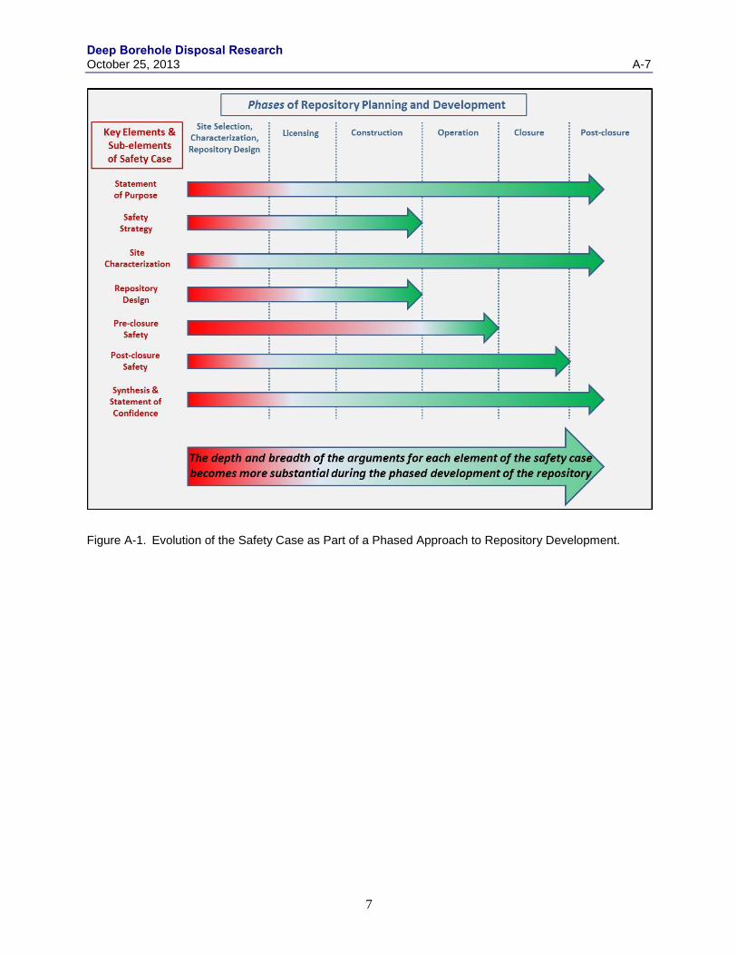
Deep Borehole Disposal Research October 25, 2013 A-7
7
Figure A-1. Evolution of the Safety Case as Part of a Phased Approach to Repository Development.

Deep Borehole Disposal Research
A-8 October 25, 2013
4.0 Existing Technical Bases for Deep Borehole Disposal
The National Academy of Sciences Committee on Waste Disposal conducted the first formal
consideration of deep geologic disposal of radioactive waste in the U.S. in the mid-1950s (NRC 1957).
Noting difficulties in deep well injection of liquid high-level radioactive waste, the committee favored
disposal of solid radioactive waste in mined salt. This seminal report prompted U.S. research in salt and
other mined repository concepts.
By the year 2000, investigations into deep borehole disposal of high-level nuclear waste had been
sporadic (e.g., O’Brien et al., 1979; Woodward and Clyde Consultants, 1983; Juhlin and Sandstedt, 1989;
Heiken et al., 1996; Gibb, 1999). MIT researchers revisited the concept (e.g., MIT 2003; Anderson 2004;
Sizer 2006; Hoag 2006; Shaikh 2007; Jensen and Driscoll 2008; Moulton 2008). These studies presented
compelling arguments that deep boreholes, 3 to 5 km into crystalline basement rock, could provide a next-
generation repository for high-level nuclear waste. Spurred by the MIT work, SNL performed thermal-
hydrologic calculations as part of a preliminary performance assessment of deep borehole disposal (Brady
et al 2009; Arnold et al 2011; Hadgu et al 2011; Arnold and Hadgu 2013) and concluded that doses to the
biosphere over one million years would likely be limited to ten orders of magnitude below current
standards (Brady et al. 2009; Wang and Lee 2010; Clayton et al 2011; Lee et al 2011; Swift et al 2011 and
2012; Hadgu et al 2012; Vaughn et al 2012; Lee et al 2012; Section 4.4 of this report).
Advances and experience in drilling large boreholes to great depths have added confidence to the
feasibility and defensibility of the deep borehole repository concept. Much of this knowledge and
experience originates from the petroleum industry, geothermal drilling, and scientific boreholes (e.g.,
Gravberg-1, Kola, and KTB). Using this accumulated knowledge, SNL researchers conducted a cost
analysis of an advanced deep borehole reference design and concluded that deep borehole disposal of
high-level radioactive waste is technically feasible (Arnold et al. 2011; Vaughn et al 2012). However, a
full-scale demonstration is needed to confirm the feasibility and safety of the deep borehole disposal
concept.
Disposal of high-level radioactive waste in a deep borehole repository is attractive for a number of
reasons, many of which also support disposal concepts for mined repositories. They include:
Post-closure safety
o rock at disposal depth has very low permeability (10-16
to 10-20
m2)
o distance to biosphere is great (3 to 5 km)
enhances waste isolation
reduces probability of human intrusion
o natural upward driving forces are weak
upward movement is not favored for dense saline groundwater at depth
geologic ages of deep water confirm that stagnation prevails at depth
o borehole sealing technology is effective and mature
o upward thermally-induced flow is minimal (Brady et al 2009; Arnold and Hadgu 2013)
o high mechanical stability of boreholes reinforced with steel casing reduces mechanical
stresses on canister
enhances canister performance (although safety case may not take credit for the
canister performance after borehole closure)
o reducing chemical conditions limit mobility of radionuclides
low solubility
high sorption
o colloid stability is limited due to high salinity
o waste is highly secure upon borehole sealing
Deep Borehole Disposal Research October 25, 2013 A-9
9
o extremely low probability of a significant dose to the biosphere
Feasibility of implementation
o technology is mature
o no need for
tunnels
underground rail or vehicle transportation systems
underground ventilation systems
underground workers
o relatively small surface footprint due to vertical configuration
o modularity allows flexibility in siting multiple smaller repositories
potential for lower transportation outlays
o suitable sites are likely abundant across the country
o technically feasible from a cost perspective (Arnold et al. 2011)
The remainder of this section reviews the existing technical and knowledge bases for disposing nuclear
waste in deep boreholes, relying heavily on the findings of the various studies to date on the subject. The
technical basis reviewed in this section specifically includes (1) the extensive hydrogeological,
geochemical, thermo-mechanical, and other technical data that has been collected relevant to deep
borehole disposal; (2) the well-known characteristics of the waste inventory; (3) the U.S. and international
experience in developing and implementing a deep borehole repository concept; and (4) the application of
current PA methodology to the evaluation of deep borehole repository performance.
Figure A-2 shows the categories of information needed for the safety case and indicates that much of this
information is available to build an initial safety case for deep borehole disposal of commercial SNF and
other DOE waste forms. Confidence statements are provided for each of the main categories of technical
information needed for a deep borehole safety case. Supporting references for each category in Figure
A-2 are identified in Appendix B. The references are an initial attempt and by no means complete.
Additional supporting references will be added to the list as the study progresses.
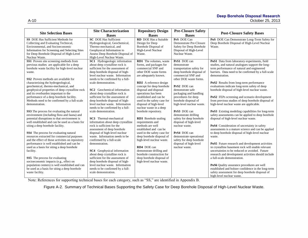
Deep Borehole Disposal Research
A-10 October 25, 2013
Site Selection Bases Site Characterization
Bases
Repository Design
Bases
Pre-Closure Safety
Bases Post-Closure Safety Bases
SS DOE Has Sufficient Methods for Collecting and Evaluating Technical,
Environmental, and Socioeconomic
Information for Screening and Selecting Sites for Deep Borehole Disposal of High-Level
Nuclear Waste.
SC DOE Has Sufficient Hydrogeological, Geochemical,
Thermo-mechanical, and
Geophysical Information to Assess Deep Borehole Disposal of
High-Level Nuclear Waste.
RD DOE Has a Suitable Design for Deep
Borehole Disposal of
High-Level Nuclear Waste.
PrS DOE Can Demonstrate Pre-Closure
Safety for Deep Borehole
Disposal of High-Level Nuclear Waste.
PoS DOE Can Demonstrate Long-Term Safety for Deep Borehole Disposal of High-Level Nuclear
Waste.
SS1 Proven site screening methods from previous studies are applicable for a deep
borehole waste facility for high-level nuclear
waste.
SS2 Proven methods are available for
characterizing the hydrogeological, geochemical, thermo-mechanical, and
geophysical properties of deep crystalline rock
and its overburden important to the performance of a deep borehole facility.
Methods need to be confirmed by a full-scale
demonstration.
SS3 The process for evaluating the natural
environment (including flora and fauna) and potential disruptions to that environment is
well established and can be used as a basis for
siting a deep borehole facility.
SS4 The process for evaluating natural
resources extracted for commercial purposes and the effect of those activities on repository
performance is well established and can be
used as a basis for siting a deep borehole facility.
SS5 The process for evaluating socioeconomic impacts (e.g., effect on
population centers) is well established and can
be used as a basis for siting a deep borehole waste facility.
SC1 Hydrogeologic information about deep crystalline rock is
sufficient for the assessment of
deep borehole disposal of high-level nuclear waste. Information
needs to be confirmed by a full-
scale demonstration.
SC2 Geochemical information
about deep crystalline rock is sufficient for the assessment of
deep borehole disposal of high-
level nuclear waste. Information needs to be confirmed by a full-
scale demonstration.
SC3 Thermal-mechanical
information about deep crystalline
rock is sufficient for the assessment of deep borehole
disposal of high-level nuclear
waste. Information needs to be confirmed by a full-scale
demonstration.
SC4 Geophysical information
about deep crystalline rock is
sufficient for the assessment of deep borehole disposal of high-
level nuclear waste. Information
needs to be confirmed by a full-scale demonstration.
RD1 The volumes, waste forms, and packages for
commercial SNF and
other DOE waste forms are adequately known.
RD2 A reference design concept for deep borehole
disposal and disposal
operations has been established and can be
used in the safety case for
disposal of high-level nuclear waste in a deep
borehole repository.
RD3 Borehole sealing
requirements and
methods are well established and can be
used in the safety case for
deep borehole disposal of high-level nuclear waste.
RD4 DOE can demonstrate drilling and
borehole construction for
deep borehole disposal of high-level nuclear waste.
PrS1 DOE can demonstrate
transportation safety for
deep borehole disposal of commercial SNF and
other DOE waste forms.
PrS2 DOE can
demonstrate safe
packaging and handling procedures for deep
borehole disposal of
high-level nuclear waste.
PrS3 DOE can
demonstrate drilling safety for deep borehole
disposal of high-level
nuclear waste.
PrS4 DOE can
demonstrate operational safety for deep borehole
disposal of high-level
nuclear waste.
PoS1 Data from laboratory experiments, field studies, and natural analogues support the long-
term performance of natural and engineered
barriers. Data need to be confirmed by a full-scale demonstration.
PoS2 Results from long-term performance evaluations indicate long-term safety of deep
borehole disposal of high-level nuclear waste.
PoS2 FEPs screening and scenario development
from previous studies of deep borehole disposal of
high-level nuclear waste are applicable.
PoS3 Existing modeling capabilities for long-term
safety assessments can be applied to deep borehole disposal of high-level nuclear waste.
PoS4 Consideration of uncertainty in safety assessments is a mature science and can be applied
to deep borehole disposal of high-level nuclear
waste.
PoS5 Future research and development activities
in crystalline basement rock will enable relevant uncertainties to be reduced or avoided. Future
research and development activities should include
a full-scale demonstration.
PoS6 Quality assurance procedures are well
established and bolster confidence in the long-term safety assessment for deep borehole disposal of
high-level nuclear waste.
Note: References for supporting technical bases for each category, such as “SS,” are identified in Appendix B.
Figure A-2. Summary of Technical Bases Supporting the Safety Case for Deep Borehole Disposal of High-Level Nuclear Waste.
Deep Borehole Disposal Research October 25, 2013 A-11
4.1 Site Selection
During the site selection process, the organization responsible for siting and development investigates one
or more sites to determine suitability with respect to various screening guidelines. Preliminary site
investigations, including any existing oil and gas drilling data, will produce a variety of technical data,
including geologic, hydrologic, geochemical, geophysical, and thermo-mechanical data at the candidate
sites. In addition to technical data, other data related to guidelines for health and safety, environmental,
socioeconomic, and economic considerations (Keeney 1980) should be gathered during the siting process.
The safety case paradigm is meant to be applied to the safety evaluation of a radioactive waste disposal
system, including the site selection process. Selection of a site for a deep borehole disposal
demonstration project does not require the rigor of selecting a disposal site, but it should be guided by
many of the same considerations related to post-closure safety. Many scientific and engineering studies
to be conducted as part of a demonstration project should be performed under the geological,
hydrological, and physic-chemical conditions that are relevant to safety at a deep borehole disposal site.
The down-selection process considers the geologic media (e.g., basement rock and overburden) and the
location or setting.
Site selection guidelines for a demonstration project evaluated in include the following technical factors
(see Section 2 of this report for detailed descriptions):
Depth to crystalline basement – (less than 2,000 m favorable)
Crystalline basement lithology – (felsic intrusive rocks preferred)
Basement structural complexity – (faults, shear zones, and tectonic complexes unfavorable)
Horizontal stress – (small differential in horizontal stress favorable)
Tectonic uplift – (low uplift rate favorable)
Geothermal heat flux – (low heat flux favorable)
Topographic relief and hydraulic gradient – (low regional topographic relief favorable)
Quaternary faults and volcanism – (Quaternary-age faulting and volcanism unfavorable)
Mineral resources potential – (Higher potential for mineral resources in crystalline basement
generally unfavorable)
For a deep borehole repository with a waste disposal zone depth from 3 to 5 km, a key selection guideline
is the depth of the top of the crystalline basement rock, which should be no deeper than approximately 2
km (Arnold et al. 2011). Other important factors, namely the permeability and stability of the rock,
overlap with factors of the hydrology, tectonic stability, and physico-chemical compatibility guidelines.
Each factor related to these guidelines must be identified and addressed to assess the ability of the site’s
natural features to meet performance objectives.
An economic/social compatibility factor, unlike the guidelines noted above, does not concern the
technical properties of a site’s natural features. This factor, nonetheless, is equally important because it
concerns the ability of disposal facility proponents to win the support of the local community and
stakeholders. The economic/social compatibility factor is evaluated based on whether community
stakeholders accept or reject the idea. Depending on the benefits and risks perceived by the stakeholders,
deep borehole disposal may or may not have an advantage over other types of repositories.

Deep Borehole Disposal Research
A-12 October 25, 2013
4.2 Site Characterization
Site characterization is needed to identify site features and their properties so that the suitability and
performance of the site can be assessed. Characterization activities include:
Examination of features and properties important to the site selection guidelines (Section 4.1),
focusing on the features that might threaten site suitability, and
Measurement of parameter values important to repository performance assessment analysis.
Features requiring characterization are formally identified through the FEPs screening process (Section
4.5).
Important site characteristics include stratigraphy, depth to the crystalline basement rock, age of
groundwater, redox conditions, salinity, vertical hydraulic gradients, fracturing, and the presence of
igneous intrusions and exploitable natural resources. Each of these characteristics provides useful
information on radionuclide transport pathways, radionuclide mobility, potential for significant disruptive
events, and/or potential radionuclide migration rates.
A wide selection of proven methods is available for characterization. They include (Vaughn et al. 2012):
Surface Based Characterization
o 3D Seismic Imaging
o Gravity Survey
o Magnetic Survey
o Electrical Resistivity Profile
Borehole-Based Characterization
o Geophysical Logging
Borehole Caliper Log
Gamma Ray Log
Resistivity Log
Spontaneous Potential Log
Temperature Log
Neutron Porosity Log
Formation Micro Imager Log
Anisotropic Shear Wave Velocity Log
Borehole Gravity Log
o Geological and Hydrological Sampling and Analyses
Drill Cuttings Lithology Log
Intermittent Coring
Fluid Samples from Packer Testing
Borehole Hydrological Testing
Drill Stem Tests of Shut-In Pressure
Drill Stem Pump Tests
Packer Testing and Packer Pump Test
Tracer Testing
Vertical Dipole Tracer Testing
Push-Pull Tracer Testing
Thermal Testing
Waste Canister Mockup Electrical Heater Test
Deep Borehole Disposal Research October 25, 2013 A-13
Borehole Seals Testing
Downhaul Force Mechanical Testing
Fluid Pressure Drawdown Test of Effective Permeability
Details of these methods and what they provide are discussed elsewhere (e.g., Vaughn et al. 2012).
Because these characterization methods are well established and can be used to collect the
hydrogeological, geochemical, thermo-mechanical, and geophysical information needed to characterize
potential sites for deep borehole disposal, DOE has sufficient means for collecting sufficient information
about deep crystalline rock to provide an assessment basis for deep borehole disposal of high-level
nuclear waste.
The information gathered to date about the hydrogeologic, geochemical, thermo-mechanical, and
geophysical characteristics of deep crystalline rock is extensive (Brady et al. 2009). These data build
confidence that the deep borehole disposal concept is viable and would meet site characterization and
performance standards. However, this information exists only as a compilation of data from various
studies conducted at different sites and as such is not complete enough at any one site to provide
sufficient characterization to address the full set of site selection guidelines for a particular site or to
perform a site-specific performance assessment. While DOE has sufficient technology and methods for
fully characterizing a demonstration or potential repository site and it has sufficient knowledge of the
general physical and chemical characteristics of deep crystalline rock, it does not have sufficient site
characterization bases for any specific site. The next step for DOE is to use the available site selection
bases to identify a site where it can conduct a full-scale pilot project to comprehensively characterize a
site for deep borehole disposal. A sufficiently characterized site of a full-scale demonstration project
would significantly augment the site assessment bases for the deep borehole repository concept (Section
5).
4.3 Deep Borehole Disposal System Design and Waste Characteristics
Deep boreholes can be engineered to accommodate the various waste volumes and waste types in the US
radioactive waste inventory (Brady et al. 2009; Arnold et al 2011). The most important feature of the
engineered barrier system (EBS) for a deep borehole repository is the borehole seal. Extensive experience
in the sealing of deep boreholes (gained largely from the petroleum industry) and the results of PA
modeling imply that the characteristics of the waste canisters and emplaced waste are of lower
importance. Many FEPs associated with the performance of the waste package, waste form, and backfill
in the disposal zone can therefore be excluded.
4.3.1 Waste Characteristics
The Nation’s high-level nuclear waste materials that need to be permanently disposed, including
commercial SNF and other DOE waste forms, have been well characterized (DOE 2002; DOE 2008) and
would be further evaluated during the development of this safety case.
Commercial SNF is the irradiated fuel withdrawn from a commercial power reactor, for which its final
disposition has not been determined. The majority of the commercial SNF is stored at the power plant
where it was generated.
Four different scenarios were developed for the once-through fuel cycle waste inventory analysis to
evaluate the projected increases in the commercial light water reactor (LWR) SNF inventory and to
provide a wide range of LWR fuel inventory for use in future analysis (Carter et al. 2011). For Inventory
Scenario 1, which assumes no replacement of existing commercial nuclear generation reactors, a total of
140,000 metric tons uranium (MTU) SNF is estimated to be discharged from reactors, and this is the
Deep Borehole Disposal Research
A-14 October 25, 2013
smallest total inventory among the four scenarios (Carter et al. 2011). Out of the total inventory, 91,000
MTU is the pressurized water reactor (PWR) SNF, with an estimated total of 209,000 assemblies, and this
is equivalent to 0.435 MTU per PWR assembly. The remaining inventory (49,000 MTU) is the boiling
water reactor (BWR) SNF. For simplification of commercial SNF inventory for this particular inventory
scenario, if the total inventory was converted to an equivalent PWR inventory, the total inventory
(140,000 MTU) is equivalent to a total of 321,540 PWR assemblies. The inventory analysis also provides
estimates of the isotopic inventory of the SNF for expected ranges of the fuel burn-up, fuel enrichment
and aging time after discharge from reactor (Carter et al. 2011).
DOE HLW is generated by the reprocessing of DOE SNF. DOE SNF was primarily generated by DOE
production reactors, but also includes naval SNF. The majority of the DOE HLW and DOE SNF is
currently stored at three DOE sites: Hanford, Savannah River, and the Idaho National Laboratory.
DOE SNF generated in production reactors supported weapons and other isotope production programs.
An example of SNF existing today from production reactors is the N-Reactor fuel stored at the Hanford
site. Radionuclide inventories for DOE SNF vary widely depending on the history and fuel design.
Projections for the number of SNF canisters that would need to be disposed of vary depending on the fuel
types, treatment and packaging arrangements and may possibly be a function of the repository design
(DOE 2008; Carter et al. 2012).
DOE HLW is typically encapsulated in a borosilicate-type glass by vitrifying the HLW solid resides:
mixing the waste solid residues with grits of glass forming elements (SiO2, B2O3, Al2O3, Na2O, etc.),
melting the mixture in a glass-making furnace and pouring the melt in a stainless steel canister for
solidification. Once the glass melt solidifies, the canister is sealed. A loaded, sealed HLW canister and
its contents constitute the final HLW waste form to be disposed of. Well over 20,000 canisters would
have to be disposed in various sizes with a range of canister inventories and heat generation rates
depending on where the HLW originated, HLW loading in the glass and its age (DOE 2002; DOE 2008;
Carter et al. 2012).
As described in Section 2, some DOE HLW/SNF is of commercial origin (e.g., damaged TMI SNF) and
will not initially be considered in the safety case described herein, but its volume and characteristics are
not sufficiently different to affect the confidence basis in a high-level waste repository safety case, if it
were to be included later.
At a minimum, the waste canister design and handling procedures must provide a high level of assurance
that waste canisters will not release radioactive materials during surface operations, emplacement in the
borehole, and borehole sealing. Acceptable procedures and designs must also be established for, if
necessary, retrieving canisters from the borehole prior to placement of the seals. Once the borehole is
sealed, retrieval of waste would be difficult; thus, if regulations require waste retrievability over the long
term, deep borehole disposal presents special challenges. After the seals are in place, the performance of
the waste canister and waste form is not highly important compared to the performance of the seals,
because the seals and natural barriers including the bedrock surrounding the borehole are expected to
preclude significant radionuclide migration to the biosphere regardless of the timing of radionuclide
releases from the waste canister and waste form.
The waste canisters for a deep borehole repository system must be designed to withstand significant
mechanical, thermal, and hydrostatic stresses during handling, emplacement, and accidental drops. The
extreme magnitudes of these stresses have been estimated and are easily handled by current waste canister
designs (Arnold et al. 2011). Full testing of these waste canister designs and their handling, emplacement,
and retrieval, however, requires a full-scale pilot project (Section 5).
Deep Borehole Disposal Research October 25, 2013 A-15
4.3.2 Deep Borehole Disposal System Design
The safety case outlined in this paper could start with the recent design concept for a deep borehole
disposal system developed by Arnold et al. (2011) for DOE. The primary components of the reference
design include:
Boreholes
o drilled and completed to a depth of approximately 5,000 m with a disposal zone in
crystalline rock between about 3,000 and 5,000 m
o 0.43 m bottom hole diameter
o 50 m spacing minimum at a bottom depth
Borehole casing system
o conductor and surface casing (cemented)
o intermediate 1 casing (surface to 1,500 m, cemented)
o intermediate 2 casing (from 1,500 to 3,000 m, lower 160 m cemented)
o guidance liner (from 3,000 to 5,000 m, perforated/slotted)
o guidance tieback (from surface to 3,000 m)
Waste canisters
o 0.27 m outside diameter, 4.2 m minimum length
o coupling connections between canisters (0.3 m diameter)
Surface handling and shielding system
Waste emplacement system
o waste canisters emplaced in 10 strings of 40 (length of each string about 192 m)
o bridge plug and cement plug above each canister string
o grouting between canisters and borehole walls (synthetic oil base mud containing
bentonite)
Borehole sealing and abandonment
o removal of guidance tieback, guidance liner, and intermediate 2 casing
o sealing using a series of cement plugs, ballast, bentonite, and fill
o bridge plugs in the upper cased section and additional cement-based fill
Operational safety assurance and monitoring
Approximately 950 boreholes would be required to dispose the projected waste inventory of commercial
SNF from the current fleet of U.S. nuclear reactors if intact fuel assemblies are loaded into the waste
canisters (Brady et al., 2009). This number reduces to 700 if used fuel rods are packed at a high density
(Arnold et al. 2011). Spacing between disposal boreholes of at least 50 m would ensure that the thermal
interference between boreholes is relatively small (Arnold et al. 2011). At 50 m spacing, the entire
projected inventory could theoretically be disposed within an area of one square mile.
The concept of operations for a deep borehole repository can borrow much from the knowledge base
acquired from mined repositories and pilot projects conducted in the U.S. and around the world. Between
1978 and 1983, as part of the Spent Fuel Test – Climax project, a 420 m borehole was drilled into the
granitic Climax stock at the Nevada Test Site to test the lowering, storage, and retrieval of canisters
containing full-size commercial PWR used fuel assemblies (Patrick, 1986). A transport cask system was
used to raise the canisters to the vertical position and lower them into the borehole where they resided for
3.5 years until retrieved. The study examined the effects of radiation, temperature, and drilling damage,
Deep Borehole Disposal Research
A-16 October 25, 2013
the handling of spent fuel, and the response of the rock. The results showed that the waste canisters
affected the surrounding rock but did not threaten the stability or safety of the facility.
The challenges for the implementation of the deep borehole disposal concept center on the extreme depths
of drilling and waste emplacement. Here, experience from the petroleum industry, geothermal drilling,
and deep scientific boreholes is precious. Based on this information, a 5,000 m borehole is likely readily
achievable with a bottom hole diameter of 0.3 m but may not be achievable at bottom hole diameters
greater than 0.5 m (Beswick 2008). Various designs for borehole casing and emplacement have been
proposed for deep borehole disposal and appear to be feasible and/or ready for a pilot project
demonstration (Woodward-Clyde Consultants, 1983; Juhlin and Sandstedt, 1989; Hoag, 2006; Beswick,
2008; Arnold et al 2011).
The borehole sealing system is an important component of the long term safety of deep borehole disposal
(Brady et al. 2009; Clayton et al 2011; Vaughn et al 2012; Lee et al 2011 and 2012; Swift et al 2011 and
2012; Section 4.4 of this report). Here, too, much knowledge and experience gained from other programs,
projects, and ventures can be utilized. The functions and characteristics of the borehole sealing system are
similar to those for the shaft sealing systems of mined repositories, namely:
Limit waste constituents reaching regulatory boundaries
Restrict water flow through the seal system
Mechanical and chemical compatibility in situ
Protect against structural failure of system components
Limit subsidence and prevent re-excavation
Utilize available construction methods and materials
The major seals of the reference design include bridge plugs, cement, and bentonite, and the processes
and technologies used to emplace them are mature (Arnold et al, 2011). The oil industry primarily uses
cementitious materials for sealing boreholes and has developed numerous placement techniques (Smith
1989, API 2000, Pusch 2008). Different classes and compositions of cements are used depending on
depth, temperature, formation properties, and fluid properties. Plugs of bentonite and other swelling clays
are routinely used to inhibit water flow and would sorb most radionuclides that have reached the seals.
Bridge plugs that would meet the required specifications are commercially available (e.g., the
Weatherford PBP bridge plug and the TechTool high-pressure bridge plug).
Although the various components of the repository design have strong technical bases, they have not been
tested together as part of a deep borehole repository concept. A pilot demonstration project would allow
testing of the repository design as a whole.
4.4 Pre-closure Safety
The analysis of safety before repository closure is a mature science based on a systematic examination of
the site, the design, and the potential initiating events caused by underlying hazards (DOE 2008). An
initiating event is a departure from normal operation that triggers an event sequence. A pre-closure safety
analysis will consist of internal and external initiating event identification, event sequence analysis,
radiological dose and consequence analysis, and criticality analysis. In this case of deep borehole
disposal the analysis will be supported by drilling safety data from the petroleum industry and waste
packaging, handling, and emplacement data from radioactive waste disposal programs and pilot projects.
Probably the most relevant pre-closure safety information comes from the Spent Fuel Test – Climax
project (Patrick 1986) and WIPP. At the Spent Fuel Test, full-size used fuel assemblies were emplaced in
a 420 m borehole and removed after 3 years (Patrick, 1986). At WIPP, there are many years of pre-
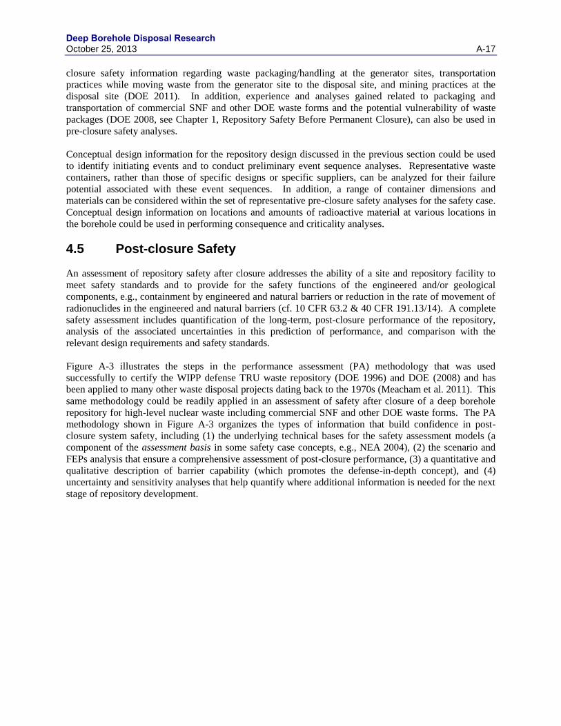
Deep Borehole Disposal Research October 25, 2013 A-17
closure safety information regarding waste packaging/handling at the generator sites, transportation
practices while moving waste from the generator site to the disposal site, and mining practices at the
disposal site (DOE 2011). In addition, experience and analyses gained related to packaging and
transportation of commercial SNF and other DOE waste forms and the potential vulnerability of waste
packages (DOE 2008, see Chapter 1, Repository Safety Before Permanent Closure), can also be used in
pre-closure safety analyses.
Conceptual design information for the repository design discussed in the previous section could be used
to identify initiating events and to conduct preliminary event sequence analyses. Representative waste
containers, rather than those of specific designs or specific suppliers, can be analyzed for their failure
potential associated with these event sequences. In addition, a range of container dimensions and
materials can be considered within the set of representative pre-closure safety analyses for the safety case.
Conceptual design information on locations and amounts of radioactive material at various locations in
the borehole could be used in performing consequence and criticality analyses.
4.5 Post-closure Safety
An assessment of repository safety after closure addresses the ability of a site and repository facility to
meet safety standards and to provide for the safety functions of the engineered and/or geological
components, e.g., containment by engineered and natural barriers or reduction in the rate of movement of
radionuclides in the engineered and natural barriers (cf. 10 CFR 63.2 & 40 CFR 191.13/14). A complete
safety assessment includes quantification of the long-term, post-closure performance of the repository,
analysis of the associated uncertainties in this prediction of performance, and comparison with the
relevant design requirements and safety standards.
Figure A-3 illustrates the steps in the performance assessment (PA) methodology that was used
successfully to certify the WIPP defense TRU waste repository (DOE 1996) and DOE (2008) and has
been applied to many other waste disposal projects dating back to the 1970s (Meacham et al. 2011). This
same methodology could be readily applied in an assessment of safety after closure of a deep borehole
repository for high-level nuclear waste including commercial SNF and other DOE waste forms. The PA
methodology shown in Figure A-3 organizes the types of information that build confidence in post-
closure system safety, including (1) the underlying technical bases for the safety assessment models (a
component of the assessment basis in some safety case concepts, e.g., NEA 2004), (2) the scenario and
FEPs analysis that ensure a comprehensive assessment of post-closure performance, (3) a quantitative and
qualitative description of barrier capability (which promotes the defense-in-depth concept), and (4)
uncertainty and sensitivity analyses that help quantify where additional information is needed for the next
stage of repository development.
Deep Borehole Disposal Research
A-18 October 25, 2013
Figure A-3. Performance Assessment Methodology (from Meacham et al. 2011).
Because the conceptual repository proposed in this study is deep borehole disposal, many of the FEPs and
associated analyses used for mined repositories are not directly applicable. For example, drift collapse
and the resulting damage to engineered barriers within the repository are excluded due to inapplicability.
Inadvertent human intrusion can be excluded based on the low probability that exploratory boreholes
would be drilled kilometers deep into crystalline bedrock. In addition, FEPs related to the degradation of
the waste package may also be excluded from the performance assessment if no credit is taken for the
performance of the waste package, as in the previous analyses (Brady et al. 2009; Clayton et al 2011;
Swift et al 2011 and 2012; Lee et al 2011 and 2012; Section 4.4 of this report). Excluding FEPs like these
from the performance assessment model is beneficial because they may introduce significant uncertainty
and may require considerable resources to characterize and implement associated uncertainty.
Assuming negligible benefit from the performance of the waste package for deep borehole disposal, the
high priority FEPs requiring further study include those involving (Brady et al. 2009, Table B-2; Sections
4.1 to 4.4 of this report):
Placement and longevity of borehole seals
Faults, fractures, and fault displacement at the site
Potential for igneous intrusion at the site
Flow and transport through seals and the excavation disturbed zone
Radionuclide diffusion into and within the surrounding bedrock
Chemical environment in the disposal zone
Deep Borehole Disposal Research October 25, 2013 A-19
Colloids and microbial activity
Thermal effects on features and transport
Gas generation
Criticality
Of these, the criticality FEPs and some or all of the FEPs related to colloids, fault displacement, and
igneous intrusion may be excluded based on low probability or low consequence depending on results of
screening calculations.
The advancements in performance assessment and other new modeling capabilities, such as the effects of
heat on fill materials, surrounding rock, and flow and transport as well as the existing knowledge base
associated with the hydrogeology of deep crystalline rock and the origin and age of groundwater at these
depths, could be used to inform and perform a safety assessment for a deep borehole repository for high-
level nuclear waste. Results from preliminary post-closure safety assessments provide confidence in the
safety of deep borehole disposal (Brady et al. 2009; Clayton et al 2011; Vaughn et al 2012; Swift et al
2011 and 2012; Lee et al 2011 and 2012; Section 4.4 of this report).
A key consideration in the assessment of post-closure safety is the identification and analysis of
uncertainties that have the potential to significantly impact the understanding of the degree of safety the
system offers. Consideration of uncertainty in the evaluation of safety after repository closure is a well-
developed science (see Appendix B, Section PoS-4) that categorizes uncertainty into two major types:
uncertainty related to the inherent randomness of the problem (such as random external events that affect
safety, e.g., seismicity) and uncertainty related to lack of measurement data (such as the uncertain
composition of the current inventory of commercial SNF and other DOE waste forms). The former type
of inherent or irreducible uncertainty is often called aleatory uncertainty and the latter type of
measurement or reducible uncertainty is often called epistemic uncertainty (Helton et al., 1998).
Epistemic uncertainties can be reduced by data-gathering methods, including additional site
characterization, design studies, fabrication and other demonstration tests, and other experiments both in
the laboratory and in underground test facilities.
Sensitivity analyses from the post-closure safety assessment provide the basis for defining the types of
tests and studies needed to reduce epistemic uncertainty and for assigning priorities for further R&D work
in the next stage of repository development. This is a key feature of the PA methodology, as indicated in
Figure A-3, which results from the iterative nature of the process wherein the current performance
assessment informs the research and development agenda necessary for the next phase of system
characterization, design, and/or implementation. In particular, the PA methodology shown in Figure A-3
does not simply encompass evaluations of repository performance and regulatory compliance, which is a
more traditional definition of PA. In early stages of repository development, as disposal at a particular
site or with a particular design concept is being considered, the methodology includes analyses that
inform the decision maker about what is important for repository performance and what, if any, “data
gaps” would need to be filled. This iterative principle has been applied to several very different disposal
concepts that advanced to licensing: DOE (1996), DOE (2008), and Greater Confinement Disposal
(Cochran et al. 2011). Repository programs use probabilistic performance assessments to help set
priorities and to guide the research portfolio.
Finally, as mentioned in Section 3.1, with regard to the elements of the safety case concept, anthropogenic
and geologic analogues provide important insight into the safety of permanent nuclear waste disposal and
bolster the case for long-term, post-closure safety. For example, isotopic analysis of groundwater in
crystalline rock at the depth of the disposal zone indicates the age of the groundwater and the potential for
natural circulation with shallow groundwaters. The presence of quaternary-age volcanic rocks or igneous

Deep Borehole Disposal Research
A-20 October 25, 2013
intrusions at depth or in the vicinity of the site suggests a potentially significant probability for future
igneous or volcanic intrusions. Related to seals, compacted bentonite clay has been observed to be highly
resistant to solute transport over geologic timescales (Neuzil 2000), and laboratory and field data indicate
that concrete can provide a durable and robust solute transport barrier (Thompson et al. 1996). These
types of observations are important in building confidence in the safety case.
4.6 Quality Assurance
One important and necessary aspect of each element of the safety case is quality assurance (QA). All
elements of repository development must be properly planned, implemented, and documented, such that
the technical basis for the safety case is repeatable, transparent, and traceable. All nuclear programs,
including radioactive waste disposal facilities, follow strict QA guidelines. These requirements are
applicable to site characterization, general collection of data for PA, PA software and models, expert
judgment activities, waste characterization, and environmental monitoring. It is expected that any facility
handling and processing high-level nuclear waste would follow similar QA requirements.
Deep Borehole Disposal Research October 25, 2013 A-21
5.0 Deep Borehole Research and Demonstration Pilot Project
The safety case supports all aspects of disposal concept development and provides a framework for
identifying and prioritizing work in those areas where further understanding is needed to build confidence
and ensure safety. A deep borehole research and demonstration pilot project could be used to build
additional confidence in those areas that would be better examined at a large scale, such as aspects of
drilling operations, borehole stability, canister emplacement and retrieval, operational efficiency, sealing
effectiveness, and safety. Examining coupled physical and chemical processes at a field scale would help
reduce residual uncertainty in these processes.
Field testing at a pilot project site should be directed toward reducing uncertainties and addressing those
technical issues that may become the focus of interveners in the licensing proceedings. These focused
research activities must be “risk-informed” in a systematic fashion by the current version of the safety
case and any associated performance assessment analyses, such as uncertainty and sensitivity analyses
which determine the parameters and processes that most affect repository performance. Thus, any test
activity potentially used to support licensing should be assigned a priority based on how much it builds
confidence in the safety case and reduces uncertainties.
Finally, it is important that a technical management and assessment structure be put in place prior to any
testing at a pilot project site. Such a structure would first consider the overall testing needs and preferred
arrangements of the site consistent with the safety case. This would lead to identification and
prioritization of demonstration and testing activities and establish their functional and operational
requirements. Sequencing of tests and demonstrations, test-to-test interference, data acquisition systems,
synergism between and among tests, and the method for evolving from initial tests (say of a single
disposal demonstration) to a long-term pilot project facility of use to the international community, all
need to be addressed prior to any planned pilot project.
Deep Borehole Disposal Research
A-22 October 25, 2013
6.0 Conclusions
Based on existing technical information and the results of preliminary performance assessments, an initial
safety case can be developed for deep borehole disposal of high-level nuclear waste including commercial
SNF and other DOE waste forms. Much of the technical basis that would be used in this initial safety
case would have to be confirmed by a full-scale demonstration. This conclusion is derived from the
following factors:
The Nation has an extensive knowledge base in drilling deep boreholes and sealing boreholes and
shafts; this basis derives largely from the petroleum industry and nuclear waste disposal programs
(e.g., WIPP)
Performance assessment (PA) methodology for nuclear waste disposal has been developed,
matured, and applied successfully (e.g., WIPP)
DOE has the experience to develop the safety case and associated licensing basis:
– Managed and developed the WIPP Compliance Certification
– DOE (2008)
– Is actively involved in international safety case projects
DOE has the experience needed for the construction and operation of a repository:
– Managed materials and wastes within EPA, U.S. NRC, and DOE regulatory frameworks
– Transported nuclear materials, including commercial SNF and other DOE waste forms,
between sites
– Developed and operated a geologic repository (WIPP)
A safety case will provide the necessary structure for organizing and synthesizing existing repository
science and identifying any issues and gaps pertaining to safe disposal of high-level nuclear waste in deep
boreholes. The safety case synthesis will help DOE to plan its future R&D activities for investigating
deep borehole disposal using a risk-informed approach that prioritizes test activities that include
laboratory and field investigations.
It should be emphasized that the DOE has not made any decisions regarding the disposition of Nation’s
high-level nuclear waste including commercial SNF and other DOE waste forms and is presently studying
options. This study provides additional information that could be used to inform DOE’s decision making
regarding management of these wastes. Furthermore, the safety case discussed herein is not intended to
site a repository. Rather, this study simply presents an approach for accelerated development of a safety
case for a potential deep borehole demonstration or repository site for the Nation’s high-level nuclear
waste.
Deep Borehole Disposal Research October 25, 2013 A-23
7.0 References
American Petroleum Institute (API) 2000. Guidance Document: Well Abandonment and Inactive Well
Practices for U.S. Exploration and Production Operations. API Bulletin E3. First edition January 31,
1993; reaffirmed June 1, 2000. Washington D.C.
Anderson, V. K. 2004. An Evaluation of the Feasibility of Disposal of Nuclear Waste in Very Deep
Boreholes. Dept. of Nuclear Engineering. Cambridge, MA, MIT.
Arnold, B.W., P.V. Brady, S.J. Bauer, C. Herrick, S. Pye, and J. Finger. 2011. Reference Design and
Operations for Deep Borehole Disposal of High-Level Radioactive Waste. SAND2011-
6749.Albuquerque, NM: Sandia National Laboratories.
Arnold, B. and T. Hadgu. 2013. “Thermal-Hydrologic Modeling of a Deep Borehole Disposal System,”
Presented at the 14th International High-Level Radioactive Waste Management Conference, April 28-May
2, 2013, Albuquerque, NM.
Bailey, L., Becker, D., Beuth, T., Capouet, M., Cormenzana, J.L., Cuñado, M., Galson, D.A., Griffault,
L., Marivoet, J., and Serres, C. 2011. PAMINA (Performance Assessment Methodologies in Application
to Guide the Development of the Safety Case): European Handbook of the state-of-the-art of safety
assessments of geological repositories—Part 1. European Commission. January 31, 2011.
http://www.ip-pamina.eu/
Becker, D.-A., et al. 2002. Testing of Safety and Performance Indicators (SPIN). Final Report. EUR
19965 EN. European Commission, Nuclear Science and Technology.
Beswick, John 2008. Status of Technology for Deep Borehole Disposal. Contract No. NP 01185, EPS
International.
Brady, Patrick V., Bill W. Arnold, Geoff A. Freeze, Peter N. Swift, Stephen J. Bauer, Joseph L. Kanney,
Robert P. Rechard, Joshua S. Stein. 2009. Deep Borehole Disposal of High-Level Radioactive Waste,
SAND2009-4401, Sandia National Laboratories, Albuquerque, NM.
Carter, J.T., A.J. Luptak, J. Gastelum, C. Stockman, A. Miller, 2011, Fuel Cycle Potential Waste
Inventory for Disposition, FCR&D-USED-2010-000031 Rev 4, Fuel Cycle Research and Development,
U.S. Department of Energy (2011).
Carter, J.T., P.O. Rodwell, B. Robinson, and B. Kehrman. 2012. Defense Waste Salt Repository. FCRD-
UFD-2012-0001 13. May 15, 2012.
Clayton, D., G. Freeze, T. Hadgu, E. Hardin, J. Lee, J. Prouty, R. Rogers, W. M. Nutt, J. Birkholzer, H.H.
Liu, L. Zheng, and S. Chu. 2011. Generic Disposal System ModelingFiscal Year 2011 Progress
Report, FCRD-USED-2011-000184, Fuel Cycle Research and Development; SAND2011-5828P, Sandia
National Laboratories, Albuquerque, NM (August, 2011).
Cochran, J.R., W.E. Beyeler, D.A. Brosseau, L.H. Brush, T.J. Brown, B. Crowe, S.H. Conrad, P.A.
Davis, T. Ehrhorn, T. Feeney, B. Fogleman, D.P. Gallegos, R. Haaker, E. Kalinina, L.L. Price, D.P.
Thomas, and S. Wirth. Compliance Assessment Document for the Transuranic Wastes in the Greater
Confinement Disposal Boreholes at the Nevada Test Site: Volume 2: Performance Assessment: Version
2. SAND2001-2977. Albuquerque, NM: Sandia National Laboratories. September 2001.
Cranwell, R.M., J.E. Campbell, J.C. Helton, R.L. Iman, D.E. Longsine, N.R. Ortiz, G.E. Runkle, and M.J.
Shortencarier. 1987. Risk Methodology for Disposal of Radioactive Waste: Final Report. SAND81-
2573, NUREG/CR-2452. Albuquerque, NM: Sandia National Laboratories.
Deep Borehole Disposal Research
A-24 October 25, 2013
DOE (U.S. Department of Energy). 1996. Title 40 CFR Part 191 Compliance Certification Application
for the Waste Isolation Pilot Plant. DOE/CAO-1996-2184.
DOE (U.S. Department of Energy). 1997. Waste Isolation Pilot Plant Disposal Phase Final
Environmental Impact Statement: Summary. DOE/EIS-0026-S-2. September 1997.
DOE (U.S. Department of Energy). 2002. Appendix A, “Inventory and Characteristics of Spent Nuclear
Fuel, High-Level Radioactive Waste, and Other Materials.” Final Environmental Impact Statement for a
Geologic Repository for the Disposal of Spent Nuclear Fuel and High-Level Radioactive Waste at Yucca
Mountain, Nye County, Nevada. DOE/EIS-0250 Office of Civilian Radioactive Waste Management.
February 2002. ADAMS Accession #ML032690552, http://adams.nrc.gov/wba/ .
DOE (U.S. Department of Energy). 2008. Yucca Mountain Repository License Application: Safety
Analysis Report. DOE/RW-0573, Revision 0. http://www.nrc.gov/waste/hlw-disposal/yucca-lic-
app/yucca-lic-app-safety-report.html#1.
DOE (U.S. Department of Energy). 2011. 10000th Shipment Celebrated at WIPP. Press release,
http://www.wipp.energy.gov/pr/2011/10,000th_Shipment_Commemoration_Release_Final.pdf
Gibb, Fergus G.F. 1999. High-temperature, very deep, geological disposal: a safer alternative for high-
level radioactive waste?, Waste Management 19: 207-211.
Heiken, G., G. Woldegabriel, R. Morley, H. Plannerer, J. Rowley. 1996. Disposition of Excess Weapon
Plutonium in Deep Boreholes – Site Selection Handbook. Los Alamos, NM, Los Alamos National
Laboratory.
Helton, J.C., J.E. Bean, J.W. Berglund, F.J. Davis, K. Economy, J.W. Garner, J.D. Johnson, R.J.
MacKinnon, J. Miller, D.G. O’Brien, J.L. Ramsey, J.D. Schreiber, A. Shinta, L.N. Smith, D.M. Stoelzel,
C. Stockman, and P. Vaughn. 1998. Uncertainty and Sensitivity Analysis Results Obtained in the 1996
Performance Assessment for the Waste Isolation Pilot Plant. SAND98-0365. Albuquerque, NM: Sandia
National Laboratories. September 1998.
Hoag, Cristopher I. 2006. Canister Design for Deep Borehole Disposal of Nuclear Waste. Dept. of
Nuclear Engineering. Cambridge, MA, MIT.
IAEA (International Atomic Energy Agency). 2011. Disposal of Radioactive Waste, Specific Safety
Requirements. IAEA Safety Series No. SSR-5. Vienna, Austria: International Atomic Energy Agency.
Jensen, K.G. and M.J. Driscoll. 2008. Siting of a Deep Borehole Repository for High Level Nuclear Waste
in the United States. Massachusetts Institute of Technology, Cambridge, MA.
Juhlin, C. and H. Sandstedt. 1989. Storage of Nuclear Waste in Very Deep Boreholes: Feasibility Study
and Assessment of Economic Potential. Part I: Geological Considerations. Part II: Overall Facility Plan
and Cost Analysis, Svensk Karnbranslehantering AB.
Keeney, R.L. 1980. Siting Energy Facilities. New York: Academic Press.
Lee, J. H., Arnold, B. W., Swift P. N., Hadgu, T., Brady P. V., Freeze G., and Wang Y. 2012. A Prototype
Performance Assessment Model for Generic Deep Borehole Repository for High-Level Nuclear Waste,
Waste Management Conference, February 26 – March 1, 2012, Phoenix, Arizona.
Lee, J. H., M. Siegel, C. Jove-Colon, and Y. Wang. 2011. A Performance Assessment Model for Generic
Repository in Salt Formation. Proceedings of the 13th International High-Level Radioactive Waste
Management Conference (IHLRWMC), April 10-14, 2011, Albuquerque, NM.
MIT (Massachusetts Institute of Technology). 2003. The Future of Nuclear Power. Massachusetts
Institute of Technology, Cambridge, MA.
Deep Borehole Disposal Research October 25, 2013 A-25
Meacham P.G., D.R. Anderson, E.J. Bonano, and M.G. Marietta. 2011. Sandia National Laboratories
Performance Assessment Methodology for Long-Term Environmental Programs: The History of Nuclear
Waste Management. SAND2011-8270. Albuquerque, NM: Sandia National Laboratories. November
2011.
Merkhofer, M.W., and R.L. Keeney. 1987. “A Multiattribute Utility Analysis of Alternative Sites for the
Disposal of Nuclear Waste.” Risk Anal. 7(2): 173-194.
Moulton, T.A. 2008. Parametric Study of the Total System Life Cycle Cost of an Alternate Nuclear Waste
Management Strategy Using Deep Boreholes. Dept. of Nuclear Engineering. Cambridge, MA, MIT.
NEA (Nuclear Energy Agency). 1999. Confidence in the Long-term Safety of Deep Geological
Repositories: Its Development and Communication, NEA 01809. Paris, France: OECD Nuclear Energy
Agency.
NEA (Nuclear Energy Agency). 2004. Post-closure Safety Case for Geological Repositories, Nature and
Purpose. NEA Report No. 3679. Paris, France: OECD/NEA. 2004.
NEA (Nuclear Energy Agency). 2008. Safety Cases for Deep Geological Disposal of Radioactive
Waste: Where Do We Stand? Symposium Proceedings, Paris, France (23-25 January 2007). Nuclear
Energy Agency Organization for Economic Cooperation and Development.
NEA (Nuclear Energy Agency). 2009. International Experiences in Safety Case for Geological
Repositories (INTESC). NEA Report No. 6251. Paris, France: OECD/NEA.
Neuzil C.E., 2000. Osmotic generation of “anomalous” fluid pressures in geological environments.
Nature, v. 403, p. 182–184.
NRC (National Research Council). 1957. The Disposal of Radioactive Waste on Land: Report of the
Committee on Waste Disposal of the Division of Earth Sciences. Publication 519. National Academy of
Science.
NRC (National Research Council). 2003. One Step at a Time: The Staged Development of Geologic
Repositories for High-Level Radioactive Waste. Washington, DC: The National Academies Press.
NRC (National Research Council). 2005. Technical Bases for Yucca Mountain Standards. Washington,
DC: The National Academies Press. 1995.
NWPA (Nuclear Waste Policy Act). 1983. Public Law 97-425; 96 Stat. 2201, as amended by P.L. 100-
203. December 22, 1987.
NWTRB (U.S. Nuclear Waste Technical Review Board). 2011. Technical Advancements and Issues
Associated with the Permanent Disposal Of High-Activity Wastes: Lessons Learned from Yucca
Mountain and Other Programs, A Report to Congress and the Secretary of Energy. June 2011.
O’Brein, M.T, L.H. Cohen, T.N. Narasimhan, T.L. Simkin, H.A. Wollenberg, W.F. Brace, S. Green, H.P.
Platt. 1979. The Very Deep Hole Concept: Evaluation of an Alternative for Nuclear Waste Disposal,
Berkeley, CA, Lawrence Berkeley Laboratory, LBL-7089.
Patrick, W.C. 1986. Spent Fuel Test – Climax: An Evaluation of the Technical Feasibility of Geologic
Storage of Spent Nuclear Fuel in Granite – Final Report, UCRL-53702, Lawrence Livermore National
Laboratory, Livermore, CA.
Powers, D.W., S.J. Lambert, S. Shaffer, L.R. Hill, and W.D. Weart, Editors. 1978. Geological
Characterization Report, Waste Isolation Pilot Plant (WIPP) Site, Southeastern New Mexico, Volume 1.
SAND78-1596. Albuquerque, NM: Sandia National Laboratories. August 1978. In Title 40 CFR Part
191 Compliance Certification Application for the Waste Isolation Pilot Plant, Appendix GCR.
DOE/CAO 1996-2184. October 1996.

Deep Borehole Disposal Research
A-26 October 25, 2013
Pusch, R. 2008. Geological Storage of Highly Radioactive Waste: Current Concepts and Plans for
Radioactive Waste Disposal. Springer-Verlag, Berlin.
Schneider J., L. Bailey, L. Griffault, H. Makino, K.-J. Röhlig, and P.A. Smith. 2011. Safety Assessment
and Safety Case Flowcharts. OECD/NEA Project on the Methods of Safety Assessment (MeSA). MeSA
Issue Paper # 2 Final. May 2011.
Shaikh, S. 2007. Effective Thermal Conductivity Measurements Relevant to Deep Borehole Nuclear
Waste Disposal. Dept. of Nuclear Engineering. Cambridge, MA, MIT.
Sizer, C.G. 2006. Minor Actinide Waste Disposal in Deep Geological Boreholes. Dept. of Nuclear
Engineering. Cambridge, MA, MIT.
Smith, D.K. 1989. Cementing. SPE Monograph Series, Volume 4. Society of Petroleum Engineers,
Richardson, Texas.
Swift, P.N., B.W. Arnold, P.V. Brady, G. Freeze, T. Hadgu, J. Lee, and Y. Wang. 2011. "Preliminary
Performance Assessment for Deep Borehole Disposal of High-Level Radioactive Waste." 2011
International High-Level Radioactive Waste Management Conference, April 10-14, 2011, Albuquerque,
NM.
Swift P. N., B.W. Arnold, P.V. Brady, G. Freeze, T. Hadgu, and J.H. Lee. 2012. Preliminary
Performance Assessment for Deep Borehole Disposal of High-Level Radioactive Waste, Materials
Research Society Symposium Proceedings, Vol. 1475, Page 375.
U.S. NRC (U.S. Nuclear Regulatory Commission). 2004. Update of the Risk-Informed Regulation
Implementation Plan. SECY-04-0068. April 23, 2004.
Van Luik, A., E. Forinash, and N. Marcos. 2011. Safety Assessment in the Context of the Safety Case.
OECD/NEA Project on the Methods of Safety Assessment (MeSA). MeSA Issue Paper # 1 Final. May
2011.
Vaughn, P., B.W. Arnold, S.J. Altman, P.V. Brady, and W.P. Gardner. 2012. Site Characterization
Methodology Report. SAND2012-7981, Albuquerque, New Mexico: Sandia National Laboratories.
Vaughn, P., G. Freeze, J. Lee, S. Chu, K.D. Huff, W.M. Nutt, T. Hadgu, R. Rogers, J. Prouty, E. Hardin,
B. Arnold, E. Kalinina, W.P. Gardner, M. Bianchi, H.H. Liu, J. Birkholzer. 2012. Generic Disposal
System Model: Architecture, Implementation, and Demonstration, FCRD-USED-2012-000430, Fuel
Cycle Research and Development; SAND2013-1539P, Sandia National Laboratories, Albuquerque, NM
(November, 2012).
Wang, Y., and J. Lee (eds.) 2010. Generic Disposal System Environment Modeling--Fiscal Year 2010
Progress Report. Prepared for U.S. Department of Energy, Office of Nuclear Energy, Fuel Cycle
Research and Development Program. Albuquerque, NM: Sandia National Laboratories.
Woodward - Clyde Consultants. 1983. Very Deep Hole Systems Engineering Studies. Columbus, OH,
ONWI.
Deep Borehole Disposal Research October 25, 2013 A-27
Appendix A1: Elements of the Safety Case Concept
The five elements of the safety case, as defined in Section 3, can be described in more detail as follows
(NEA 2004):
A clear statement of purpose is required to set the context of the safety case relative to the
decision it is informing. This includes an outline of the program and the current stage (see
Figure A-1) or decision point within the program against which the safety case is used to inform.
This will set the context in which the defensibility of the safety case and the importance of
remaining uncertainties can be judged. It also provides the context for evaluating system
performance. The current applicable regulatory performance goals (40 CFR 191 and 10 CFR 60)
may evolve toward goals and safety indicators similar to those that exist for other repository
programs (Bailey et al. 2011). These types of performance goals and indicators can be used at
early stages for focusing the safety assessment analyses towards informing future R&D. In later
stages of the program, the system performance will be compared directly to whatever safety
metrics are prescribed in the regulations.
The safety strategy is the high-level approach adopted for achieving safe disposal, and includes
(a) an overall management strategy, (b) a siting and design strategy, and (c) an assessment
strategy. Two important principles of the safety strategy are (1) public and stakeholder
involvement in key aspects of siting, design, and assessment and (2) alignment of the safety case
with the existing legal and regulatory framework. The safety strategy must be sufficiently
flexible to cope with unexpected site features or technical difficulties and uncertainties that may
be encountered, as well as to take advantage of advances in scientific understanding and
engineering techniques, as the project progresses. The siting and design strategy is generally
based on principles that favor robustness and minimize uncertainty, including the use of the
multi-barrier concept. Similarly, the assessment strategy must ensure that safety assessments
capture, describe, and analyze uncertainties that are relevant to safety, and investigate their
effects.
Site Characterization and Repository Design contains many parts of the assessment basis
element of the safety case concept commonly used internationally (NEA 2004), and includes a
description of (a) the primary characteristics and features of the repository site and how they will
interact with waste degradation and migration processes, (b) the location and layout of the
repository (or guidelines by which the location and layout will be determined), (c) a description
of the engineered barriers and how they will be constructed and emplaced, and (d) a discussion
of how the engineered and natural barriers (i.e., the multiple-barrier concept) will function
synergistically. The descriptions should be based on existing scientific and technical information
and understanding, and include plans for reducing existing uncertainty in this technical and
scientific basis. The foregoing description should be centered on the characterization of those
safety-bearing components or features of the repository that are “important to waste isolation”
(cf. 10 CFR 63). Site characterization and repository design evolves into implementation after a
regulatory decision to authorize construction, when the development then proceeds to the
construction phase (Figure 1). In the earliest phases of the repository program it includes the site
selection process and associated selection guidelines.
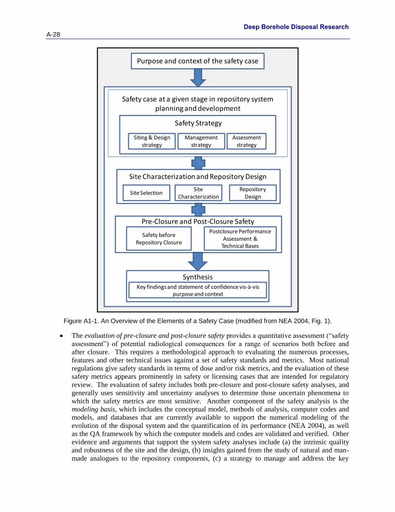
Deep Borehole Disposal Research
A-28 October 25, 2013
Figure A1-1. An Overview of the Elements of a Safety Case (modified from NEA 2004, Fig. 1).
The evaluation of pre-closure and post-closure safety provides a quantitative assessment (“safety
assessment”) of potential radiological consequences for a range of scenarios both before and
after closure. This requires a methodological approach to evaluating the numerous processes,
features and other technical issues against a set of safety standards and metrics. Most national
regulations give safety standards in terms of dose and/or risk metrics, and the evaluation of these
safety metrics appears prominently in safety or licensing cases that are intended for regulatory
review. The evaluation of safety includes both pre-closure and post-closure safety analyses, and
generally uses sensitivity and uncertainty analyses to determine those uncertain phenomena to
which the safety metrics are most sensitive. Another component of the safety analysis is the
modeling basis, which includes the conceptual model, methods of analysis, computer codes and
models, and databases that are currently available to support the numerical modeling of the
evolution of the disposal system and the quantification of its performance (NEA 2004), as well
as the QA framework by which the computer models and codes are validated and verified. Other
evidence and arguments that support the system safety analyses include (a) the intrinsic quality
and robustness of the site and the design, (b) insights gained from the study of natural and man-
made analogues to the repository components, (c) a strategy to manage and address the key
Safety strategy
Safety case at a given stage in repository system planning and development
Purpose and context of the safety case
Siting & Design strategy
Management strategy
Assessment strategy
Safety before Repository Closure
Synthesis
Pre-Closure and Post-Closure SafetyPostclosure Performance
Assessment & Technical Bases
Key findings and statement of confidence vis-à-vis purpose and context
Site Characterization and Repository Design
Site SelectionRepository
Design
Safety Strategy
Site Characterization
Deep Borehole Disposal Research October 25, 2013 A-29
residual uncertainties identified by the uncertainty and sensitivity analyses, and (d) a
performance confirmation program to monitor the repository for a period of time after the waste
has been emplaced.
A statement of confidence is required to justify a positive decision to proceed to the next phase of
planning or implementation. It is based on a synthesis of the analyses and arguments developed
and the supporting evidence gathered, and includes a discussion of completeness to ensure that
all important issues have been addressed. The statement of confidence recognizes the existence
of open issues and residual uncertainties, and perspectives about how they can be addressed in
the next phase(s), if they are determined to be important to safety. The audience of the safety
case must decide whether it believes the reasoning that is presented is adequate, and on that basis
whether it shares the confidence of the safety case author.
Deep Borehole Disposal Research
A-30 October 25, 2013
Appendix B1: Supporting Bibliography for Existing Technical Bases for Deep Borehole Disposal of High-Level Nuclear Waste
This appendix provides a supporting bibliography for Section 4 of this document. The references cited
below are organized according to the subsection titles from Section 4 and, in particular, to the categories
listed in Figure 2 (i.e., SS, SC, RD, PrS and PoS). Note that some references are listed in multiple
categories as the references have information relevant to them.
B1.1 Site Selection (SS) Basis
This section provides supporting references for site selection studies and processes conducted in a broad
sense for crystalline basement rocks that are applicable to screening and evaluating a site for a deep
borehole repository, utilizing siting factors appropriate for a radioactive waste repository. These included
the evaluation of ecology, socioeconomics, geology, hydrology, seismic and igneous activity,
geomechanical, geochemical, and thermodynamic properties of crystalline rock, and a collection of
general science activities not easily categorized in the previously mentioned disciplines. The section also
includes references related to the site characterization activities for WIPP and other projects that could be
applicable for a deep borehole repository.
Baumgartner, J., T. Gandy, T. Hettkamp, and D. Teza (2007), Drilling of hot and fractured granite at
Soultz-sous- Forêts, ENGINE Mid-Term Conference, January 9-12, 2007, GFZ, Potsdam.
Beardsmore, G. (2007), The burgeoning Australian geothermal energy industry, Geo-Heat Centre
Quarterly Bulletin, 28, Oregon Institute of Technology, Klamath Falls, OR.
BSC (Bechtel SAIC Company) 2004. Yucca Mountain Site Description. TDR-CRW-GS-000001 REV 02
ICN 01. Two volumes. Las Vegas, Nevada: Bechtel SAIC Company.
Chapman, N. and F.G.F. Gibb (2003), A truly final waste management solution – Is very deep borehole
disposal a realistic option for HLW or fissile material?, Radwaste Solutions, July/August, p. 26-35.
Daniels, D. L., R. P. Kucks, and P. L. Hill, Illinois, Indiana, and Ohio Magnetic and Gravity Maps and
Data, U.S.G.S., DS, 321, 2008.
Dawson, P.R., and J.R. Tillerson. 1977. “Comparative Evaluations of the Thermomechanical Responses
for Three High Level Waste Canister Emplacement Alternatives.” SAND77-0388. Albuquerque, NM:
Sandia National Laboratories.
Di Maio, R., P. Mauriello, D. Patella, Z. Petrillo, S. Piscitelli, and A. Siniscalchi (1998), Electric and
electromagnetic outline of the Mount Somma-Vesuvius structural setting, Journal of Volcanology and
Geothermal Research, 82(1-4), 219-238.
DOE (U.S. Department of Energy). 1980. “Waste Isolation pilot Plant Final Environmental Impact
Statement.” DOE/EIS-0026.
DOE (U.S. Department of Energy). 2000. “Pioneering Nuclear Waste Disposal.” DOE/CAO 00-3124.
DOE (U.S. Department of Energy). 2008. Yucca Mountain Repository License Application: Safety
Analysis Report. DOE/RW-0573, Revision 0. http://www.nrc.gov/waste/hlw-disposal/yucca-lic-
app/yucca-lic-app-safety-report.html#1.
Duchane, Dave and Don Brown (2002), Hot dry rock (HDR) geothermal energy research and
development at Fenton Hill, New Mexico, Geo-Heat Centre Quarterly Bulletin, 23, Oregon Institute of
Technology, Klamath Falls, OR.
Deep Borehole Disposal Research October 25, 2013 A-31
Elliot Geophysical Company. 1976. “A Laboratory Investigation of the Magnetic, Density and
Resistivity Physical Properties of Drill Core Samples from A.E.C. No. 8 Well, Section 11.” T 22 S, R 31
E. Tucson, AZ: Elliot Geophysical Company.
Foster, R.W. 1974. “Oil and Gas Potential of a Proposed Site for the Disposal of High-Level
Radioactive Waste.” ORNL/SUB-4423/l. Socorro, NM: New Mexico Bureau of Mines and Mineral
Resources, New Mexico Institute of Mining and Technology.
Freifeld, Barry and Stefan Finsterle, 2010, Imaging Fluid Flow in Geothermal Wells Using Distributed
Thermal Perturbation Sensing, Lawrence Berkeley National Laboratory.
Gallé, C., 1994, Neutron porosity logging and core porosity measurements in the Beauvoir granite, Massif
Central Range, France, J. of Applied Geophysics, vol. 32, 125-137.
Glass, R.S. 1981. “Effects of Radiation on the Chemical Environment Surrounding Waste Canisters in
Proposed Repository Sites and Possible Effects on the Corrosion Process.” SAND81-1677.
Albuquerque, NM: Sandia National Laboratories.
Goad, D. 1979. “A Compilation of Site Selection Criteria, Considerations and Concerns Appearing in
the Literature on the Deep Geologic Disposal of Radioactive Wastes.” EEG-1. Santa Fe, NM:
Environmental Evaluation Group.
Heiken, G., G. Woldegabriel, R. Morley, H. Plannerer, J. Rowley, 1996, Disposition of Excess Weapon
Plutonium in Deep Boreholes – Site Selection Handbook. Los Alamos, NM, Los Alamos National
Laboratory.
Hinkebein, T. E., and P.F. Hlava. 1978. “Microstructural Interactions of Geologic Media with Waste
Radionuclides.” SAND78-0108. Albuquerque, NM: Sandia National Laboratories.
Holmes, R.R., Jr., Terrio, P.J., Harris, M.A., and Mills, P.C., 2001, Introduction to Field Methods for
Hydrologic and Environmental Studies. U.S. Geological Survey Open-File Report 01-50. p. 236 Chapter
4 Ground Water Data Collection.
Hunter, T.O. 1979. Waste Isolation Pilot Plant (WIPP) Experimental Program. SAND79-1950C.
Waste Isolation Performance Assessment and In-Situ Testing, Proceedings of the U.S./FRG Bilateral
Workshop, Berlin, Germany (October 1-5, 1979). ONWI-88. Springfield, VA: National Technical
Information Service. 340-345.
Hunter, T.O., C.L. Christensen, R.V. Matalucci, W.R. Wawersik, and M.A. Molecke. 1981. Summary of
Research and Development Activities Related to the U.S./FRG Cooperative Program on Nuclear Waste
Management. U.S./FRG Bilateral Meeting, Bonn, Germany (June 8-12, 1981). SAND81-1204C.
Hunter, T.O. 1982. Nuclear Waste Disposal: Technical Issues and Status. SAND82-2238C. Institute
for Nuclear Materials Management Seminar on Spent Fuel Management and Waste Disposal,
Washington, DC (October 20-22, 1982).
Jensen, K.G. and M.J. Driscoll. 2008. Siting of a Deep Borehole Repository for High Level Nuclear Waste
in the United States. Massachusetts Institute of Technology, Cambridge, MA.
Juhlin, C. and H. Sandstedt. 1989. Storage of Nuclear Waste in Very Deep Boreholes: Feasibility Study
and Assessment of Economic Potential. Part I: Geological Considerations. Part II: Overall Facility Plan
and Cost Analysis, Svensk Karnbranslehantering AB.
Keeney, R.L. 1980. Siting Energy Facilities. New York: Academic Press.
Keller, G.R., and A.M. Rogers. 1978. “Central Basin Platform Seismicity for the period October 1, 1977,
to June 30, 1978.” Open-File Report 78-1100. Denver, CO: U.S. Geological Survey.
Deep Borehole Disposal Research
A-32 October 25, 2013
Keller, G.R., A.M. Rogers, R.J. Lund, and C.D. Orr. 1981. “A Seismicity and Seismic-tectonic Study of
the Kermit Seismic Zone, Texas.” Open-File Report 81-37. Denver, CO: U.S. Geological Survey.
Lomenick, T.F. 1996. “The Siting Record: An Account of the Programs of Federal Agencies and Events
That Have Led to the Selection of a Potential Site for Geologic Repository for High Level Radioactive
Waste.” ORNL/TM-12940. Oak Ridge, TN: Oak Ridge National Laboratory.
Matalucci, R.V., C.L. Christensen, T.O. Hunter, M.A. Molecke, and D.E. Munson. 1982. “Waste
Isolation Pilot Plant (WIPP) Research and Development Program: In Situ Testing Plan.” March 1982.
SAND81-2628. Albuquerque, NM: Sandia National Laboratories.
Massachusetts Institute of Technology (MIT). 2003. The Future of Nuclear Power. Massachusetts
Institute of Technology, Cambridge, MA.
Merkhofer, M.W., and R.L. Keeney. 1987. “A Multiattribute Utility Analysis of Alternative Sites for the
Disposal of Nuclear Waste.” Risk Anal. 7(2): 173-194.
Mora, C.J. 1999. “Sandia and Waste Isolation Pilot Plant: 1974-1999.” SAND99-1482. Albuquerque,
NM: Sandia National Laboratories.
Moulton, T.A. 2008. Parametric Study of the Total System Life Cycle Cost of an Alternate Nuclear Waste
Management Strategy Using Deep Boreholes. Dept. of Nuclear Engineering. Cambridge, MA, MIT.
NAS (National Academy of Sciences), 1957, The Disposal of Radioactive Waste on Land.
http://www.nap.edu/openbook.php?record_id=10294.
NEA (Nuclear Energy Agency). 2008. Safety Cases for Deep Geological Disposal of Radioactive
Waste: Where Do We Stand? Symposium Proceedings, Paris, France (23-25 January 2007). Nuclear
Energy Agency Organization for Economic Cooperation and Development.
NEA (Nuclear Energy Agency). 2009. International Experiences in Safety Case for Geological
Repositories (INTESC). NEA Report No. 6251. Paris, France: OECD/NEA.
NIREX, 2004, A Review of the Deep Borehole Disposal Concept, Report N/108, United Kingdom Nirex
Limited.
Nowak, E.J. 1982. “The Diffusion of Cs (I) and Sr (II) in Liquid-Saturated Beds of Backfill Materials.”
SAND82-0075. Albuquerque, NM: Sandia National Laboratories.
Nowak, E.J. 1980. “Radionuclide Sorption and Migration Studies of Getters for Backfill Barriers.”
SAND79-1110. Albuquerque, NM: Sandia National Laboratories.
NRC (National Research Council). 1957. The Disposal of Radioactive Waste on Land: Report of the
Committee on Waste Disposal of the Division of Earth Sciences. Publication 519. National Academy of
Science.
NRC (National Research Council). 2003. One Step at a Time: The Staged Development of Geologic
Repositories for High-Level Radioactive Waste. Washington, DC: The National Academies Press.
NWTRB (U.S. Nuclear Waste Technical Review Board). 2011. Technical Advancements and Issues
Associated with the Permanent Disposal Of High-Activity Wastes: Lessons Learned from Yucca
Mountain and Other Programs, A Report to Congress and the Secretary of Energy. June 2011.
O’Brein, M.T, L.H. Cohen, T.N. Narasimhan, T.L. Simkin, H.A. Wollenberg, W.F. Brace, S. Green, H.P.
Platt. 1979. The Very Deep Hole Concept: Evaluation of an Alternative for Nuclear Waste Disposal,
Berkeley, CA, Lawrence Berkeley Laboratory, LBL-7089.
Patrick, W.C. 1986. Spent Fuel Test – Climax: An Evaluation of the Technical Feasibility of Geologic
Storage of Spent Nuclear Fuel in Granite – Final Report, UCRL-53702, Lawrence Livermore National
Laboratory, Livermore, CA.
Deep Borehole Disposal Research October 25, 2013 A-33
Polsky, Y., Louis Capuano Jr., John Finger, Michael Huh, Steve Knudsen, A.J. Chip Mansure, David
Raymond, and Robert Swanson (2008). Enhanced Geothermal Systems (EGS) Well Construction
Technology Evaluation Report, SAND2008-7866, Sandia National Laboratories, Albuquerque, NM.
Pusch, R. and G. Ramqvist (2007), Borehole project – Final report of Phase 3. SKB report R-07-58.
Pusch, R. 2008. Geological Storage of Highly Radioactive Waste: Current Concepts and Plans for
Radioactive Waste Disposal. Springer-Verlag, Berlin.
Reilinger, R., L. Brown, and D.W. Powers. 1980. “New Evidence for Tectonic Uplift in the Diablo
Plateau Region, West Texas.” SAND79-2046J. Albuquerque, NM: Sandia National Laboratories.
Rogers, A.M., and A. Malkiel. 1979. “A Study of Earthquakes in the Permian Basin of Texas- New
Mexico.” Bulletin of the Seismological Society of America 69(3): 843-865.
Sandia National Laboratories (SNL). 1977. “Preliminary Review Copy--Draft Environmental Impact
Statement for Waste Isolation Pilot Plant, Eddy County, New Mexico.” SAND77-0650. Albuquerque,
NM: Sandia National Laboratories. Santos, H. 1987. RADCOMP V1.5 User Reference Manual.
Carlsbad, NM: Sandia National Laboratories, Waste Isolation Pilot Plant (WIPP) Records Center.
Saling, James H. and Audeen W. Fentiman (editors) (2001), Radioactive Waste Management, 2nd edition,
Taylor and Francis Publishers, New York.
Sanchez, Lawrence C., Jonathon S. Rath, Richard Aquilar, Holly R. Trellue, Kyle Cochrane, Larry L.
Taylor, and Jim R. Wilson (1998), Nuclear Dynamics Consequence Analysis (NDCA) for the Disposal of
Spent Nuclear Fuel in an Underground Geologic Repository, SAND98-2208, Sandia National
Laboratories, Albuquerque, NM.
Sapiie, B., M. J. Driscoll, and K. G. Jensen, 2010, Regional Examples of Geological Settings for Nuclear
Waste Disposal in Deep Boreholes, Rep. MIT-NFC-TR-113, 40 pp, Center for Afvanced Nuclear Energy
Systems, Massachusetts Institute of Technology, Cambrige, MA.
Smith, B. D., J. D. Abraham, J. C., Cannia, B. J. Minsley, L. B. Ball, G. V. Steele, M. Deszcz-Pan,
Helicopter electromagnetic and magnetic geophysical survey data, Swedeburg and Sprague study areas,
eastern Nebraska, May 2009. U. S. G. S. Open File Report, OFR 2010-1288, 2011.
Sutherland, H.J., and D.E. Munson. 1983. “Subsidence Prediction for High Extraction Mining Using
Complementary Influence Functions.” SAND82-2949. Albuquerque, NM: Sandia National
Laboratories.
Sweet, J.N. 1979. “Pressure Effects on Thermal Conductivity and Expansion of Geologic Materials.”
SAND78-1991. Albuquerque, NM: Sandia National Laboratories.
Thorne, B.J. 1980. “Drift Response to Elevated Temperature.” SAND80-7086. Albuquerque, NM:
Sandia National Laboratories.
Tillerson, J.R., and M.M. Madsen. 1978. “Thermoplastic Capabilities for the SANDIA-BMINES
Program.” SAND77-0378. Albuquerque, NM: Sandia National Laboratories.
Woodward - Clyde Consultants. 1983. Very Deep Hole Systems Engineering Studies. Columbus, OH,
ONWI.
Deep Borehole Disposal Research
A-34 October 25, 2013
B1.2 Site Characterization (SC) Basis
This section provides supporting references for site characterization studies and processes conducted in a
broad sense for crystalline basement rocks that are applicable to screening and evaluating a site for a deep
borehole repository. The section also includes references related to the site characterization activities for
WIPP and other projects that could be applicable for a deep borehole repository.
Ariffin, T., G. Solomon, S. Ujang, M. Bee, S. Jenkins, C. Corbett, G. Dorn, H. Ozdemir, C. Pearse, 1995,
Seismic tools for reservoir management, Oilfield Review, vol. 7, no. 4, pp. 4-17.
Becker, D.-A., et al. 2002. Testing of Safety and Performance Indicators (SPIN). Final Report. EUR
19965 EN. European Commission, Nuclear Science and Technology.
Berner, U. (1990), A Thermodynamic Description of the Evolution of Porewater Chemistry and Uranium
Speciation during the Degradation of Cement. PSI Bericht Nr. 62. Paul Scherrer Institut, Würenlingen
and Villigen, Switzerland.
Beswick, John (2008), Status of Technology for Deep Borehole Disposal. Contract No. NP 01185, EPS
International.
Brady, Patrick V., Bill W. Arnold, Geoff A. Freeze, Peter N. Swift, Stephen J. Bauer, Joseph L. Kanney,
Robert P. Rechard, Joshua S. Stein. 2009. Deep Borehole Disposal of High-Level Radioactive Waste,
SAND2009-4401, Sandia National Laboratories, Albuquerque, NM.
Chapman, N. and F.G.F. Gibb (2003), A truly final waste management solution – Is very deep borehole
disposal a realistic option for HLW or fissile material?, Radwaste Solutions, July/August, p. 26-35.
Chen, Jui-Sheng, Chen-Wuing Liu, Yi-Chieh Chan, Chuen-Fa Ni, and Ke-Kang Kao, 2011, Effect of
transverse dispersion on solute transport in a vertical dipole flow test with a tracer, J. of Hydrology, vol
402, no. 3-4, p. 206-216.
DOE (U.S. Department of Energy). 2008. Yucca Mountain Repository License Application: Safety
Analysis Report. DOE/RW-0573, Revision 0. http://www.nrc.gov/waste/hlw-disposal/yucca-lic-
app/yucca-lic-app-safety-report.html#1.
Dosch, R.G. 1980. “Assessment of Potential Radionuclide Transport in Site-Specific Geologic
Formations.” SAND79-2468. Albuquerque, NM: Sandia National Laboratories.
Duchane, Dave and Don Brown (2002), Hot dry rock (HDR) geothermal energy research and
development at Fenton Hill, New Mexico, Geo-Heat Centre Quarterly Bulletin, 23, Oregon Institute of
Technology, Klamath Falls, OR.
Greer, W.B. and D.R. Crouthamel. (1996), In situ hydraulic performance of cement borehole seals. In
Sealing of Boreholes and Underground Excavations in Rock. Lyons, W.C. and G.J. Plisga. (2005.)
Guven,O., R. W. Falta, F.J. Molz and J.G. Melvillei, 1985, Analysis and interpretation of single-well
tracer tests in stratified aquifers, Water Resources Research, vol. 21, p. 676-684.
Haggerty, Roy, Sean W. Fleming, Lucy C. Meigs and Sean A. McKenna, 2001, Tracer tests in a fractured
dolomite. 2. Analysis of mass transfer in single-well injection-withdrawal tests, Water Resources
Research, vol. 37, p. 1129-1142.
Hart, J.S. and J.K. Register. 1982. “A Description of the Site and Preliminary Design Validation
Program for the WIPP Site.” TME-3063, Rev 1.
Healey, D. L., F. G. Clutsom, and D. A. Glover, 1986, Borehole Gravity Meter Survey in Drillhole USW
G-4, Yucca Mountain Area, Nye County, Nevada, USGS-OFR-86-205, U.S. Geological Survey, Denver,
CO.
Deep Borehole Disposal Research October 25, 2013 A-35
Keys, W. Scott, 1989, Borehole Geophysics Applied to Ground-Water Investigations, Techniques of
Water Resources Investigations, Chapter E2, U.S. Geological Survey.
Leap, Darrel I. and Paul G. Kaplan, 1988, A single-well tracing method for estimating regional advective
velocity in a confined aquifer: Theory and preliminary laboratory verification, Water Resources Research,
vol. 24, p. 993-998.
Loehr, C.A. 1979. “Mineralogical and Geochemical Effects of Basaltic Dike Intrusion into Evaporite
Sequences near Carlsbad, New Mexico.” MS thesis. Socorro, NM: New Mexico Institute of Mining and
Technology.
Lynch, A.W. 1979. Migration of Cesium in Dolomite From the Rustler Formation in the Los Medaños
Area in Southeastern New Mexico. SAND78-1179C. Scientific Basis for Nuclear Waste Management,
Proceedings of the Symposium on Science Underlying Radioactive Waste Management, Materials
Research Society Annual Meeting, Boston, MA (November 28-December 1, 1978
Lynch, A.W., and R.G. Dosch. 1980. “Sorption Coefficients for Radionuclides on Samples from the
Water-Bearing Magenta and Culebra Members of the Rustler Formation.” SAND80-1064. Albuquerque,
NM: Sandia National Laboratories.
Lynch, A.W., R.G. Dosch, and C.R. Hills. 1981. “Migration of Cesium-137 through a Solid Core of
Magenta Dolomite Taken from the Rustler Formation in Southeastern New Mexico.” SAND80-1259.
Albuquerque, NM: Sandia National Laboratories.
Manning, C.E. and S.E. Ingebritsen. 1999. Permeability of the continental crust: Implications of
geothermal data and metamorphic systems, Reviews of Geophysics, 37: 127-150.
McTigue, D.F. 1987. “Flow to a Heated Borehole in Fluid-Saturated Thermoelastic Rock.” EOS
Transactions, American Geophysical Union 68(44): 1295.
Meigs, Lucy C. and Richard L. Beauheim, 2001, Tracer tests in a fractured dolomite. 1. Experimental
design and observed tracer recoveries, Water Resources Research, vol. 37, p. 1113-1128.
Munson, D.E., A.F. Fossum, and P.E. Senseny. 1989. “Advances in Resolution of Discrepancies
Between Predicted and Measured In Situ WIPP Room Closures.” SAND88-2948. Albuquerque, NM:
Sandia National Laboratories.
Neretnieks, Ivars, 2007, Single well injection withdrawal tests (SWIW) in fractured rock - Some aspects
on interpretation, SKB R-07-54, Svensk Kärnbränslehantering AB, Stockholm, Sweden.
Neuzil C.E., 2000. Osmotic generation of “anomalous” fluid pressures in geological environments.
Nature, v. 403, p. 182–184.
Park, Y.-J., E.A. Sudicky, and J.F. Sykes, 2009, Effects of shield brine on the safe disposal of waste in
deep geologic environments, Advances in Water Resources 32: 1352-1358 (2009).
Patrick, W.C. 1986. Spent Fuel Test – Climax: An Evaluation of the Technical Feasibility of Geologic
Storage of Spent Nuclear Fuel in Granite – Final Report, UCRL-53702, Lawrence Livermore National
Laboratory, Livermore, CA.
Powers, D.W., S.J. Lambert, S. Shaffer, L.R. Hill, and W.D. Weart, Editors. 1978. Geological
Characterization Report, Waste Isolation Pilot Plant (WIPP) Site, Southeastern New Mexico, Volume 1.
SAND78-1596. Albuquerque, NM: Sandia National Laboratories. August 1978. In Title 40 CFR Part
191 Compliance Certification Application for the Waste Isolation Pilot Plant, Appendix GCR.
DOE/CAO 1996-2184. October 1996.
Register, J.K. 1981. “Rubidium-Strontium and Related Studies of the Salado Formation, Southeastern
New Mexico.” SAND81-7072. Albuquerque, NM: Sandia National Laboratories.
Deep Borehole Disposal Research
A-36 October 25, 2013
Register, J.K, and D.G. Brookins. 1980. “Rb-Sr Isochron Age of Evaporite Minerals from the Salado
Formation (Late Permian), Southeastern New Mexico.” Isochron/West 29: 39-42.
Reimus, Paul W. and Timothy J. Callahan, 2007, Matrix diffusion rates in fractured volcanic rocks at the
Nevada Test Site: Evidence for a dominant influence of effective fracture apertures, Water Resources
Research, 43, W07421, doi:10.1029/2006WR005746.
Roos, Gillian N., 2009, Development of the Dipole Flow and Reactive Tracer Test (DFRTT) for Aquifer
Parameter Estimation, M.S. Thesis, University of Waterloo, Waterloo, Canada.
Sanford, William E., Peter G. Cook, and John C. Dighton, 2002, Analysis of a vertical dipole tracer test in
highly fractured rock, Ground Water, vol. 40, no. 5, p. 535-542.
Selker, John S., Luc The´venaz, Hendrik Huwald, Alfred Mallet, Wim Luxemburg, Nick van de Giesen,
Martin Stejskal, Josef Zeman, Martijn Westhoff, and Marc B. Parlange, 2006, Distributed fiber-optic
temperature sensing for hydrologic systems, Water Resources Research, vol. 42, W12202,
doi:10.1029/2006WR005326, 2006.
Shaikh, S. 2007. Effective Thermal Conductivity Measurements Relevant to Deep Borehole Nuclear
Waste Disposal. Dept. of Nuclear Engineering. Cambridge, MA, MIT.
Sizer, C.G. 2006. Minor Actinide Waste Disposal in Deep Geological Boreholes. Dept. of Nuclear
Engineering. Cambridge, MA, MIT.
Standard Handbook of Petroleum & Natural Gas Engineering, 2nd ed. Gulf Professional Publishing
(Elsevier), Burlington, Mass.
SNL 2008. Performance Confirmation Plan. TDR-PCS-SE-000001 REV 05 ADD 01. Las Vegas,
Nevada: Sandia National Laboratories.
Stober, I. and K. Bucher. 2007. Hydraulic properties of the crystalline basement, Hydrology Journal, 15:
213-224.
Theis, Charles V. (1935). The relation between the lowering of the piezometric surface and the rate and
duration of discharge of a well using ground-water storage. Transactions, American Geophysical Union
16: 519–524.
Thompson, T.W., W.E. Coons, J.L. Krumhansl, and F.D. Hansen (1996), Inadvertent Intrusion Borehole
Permeability. ERMS 241131. Sandia National Laboratories, Carlsbad, NM.
Thorne, B.J. 1980. “Drift Response to Elevated Temperature.” SAND80-7086. Albuquerque, NM:
Sandia National Laboratories.
Unterberger, R.R. 1981. “Final Report on Subsurface Radar Applications in the Delaware Basin,
Covering the Period June 1, 1980 through January 31, 1981.” College Station, TX: Texas A&M
University, Department of Geophysics.
Vaughn, P., B.W. Arnold, S.J. Altman, P.V. Brady, and W.P. Gardner. 2012. Site Characterization
Methodology Report. SAND2012-7981, Albuquerque, New Mexico: Sandia National Laboratories.
Vosteen, H.D. and R. Schellschmidt, 2003, Influence of temperature on thermal conductivity, thermal
capacity and thermal diffusivity for different rock types, Physics and Chemistry of the Earth, 28: 499-509,
1474-7065/03/$ doi:10.1016/S1474-7065(03)00069-X (2003).
Wightman, W. E., F. Jalinoos, P. Sirles, and K. Hanna, 2003, Application of Geophysical Methods to
Highway Related Problems. Federal Highway Administration, Central Federal Lands Highway Division,
Lakewood, CO, Publication No. FHWA-IF-04-021, September 2003.
http://www.cflhd.gov/resources/agm/ .
Deep Borehole Disposal Research October 25, 2013 A-37
Woodward - Clyde Consultants. 1983. Very Deep Hole Systems Engineering Studies. Columbus, OH,
ONWI.
B1.3 Repository Design (RD) Basis
This section provides supporting references for the repository design studies and processes conducted in a
broad sense for crystalline basement rocks that are applicable for a deep borehole repository. The section
also includes references related to the repository design activities for WIPP and other projects that could
be applicable for a deep borehole repository.
American Petroleum Institute (API) 2000. Guidance Document: Well Abandonment and Inactive Well
Practices for U.S. Exploration and Production Operations. API Bulletin E3. First edition January 31,
1993; reaffirmed June 1, 2000. Washington D.C.
Anderson, V. K. 2004. An Evaluation of the Feasibility of Disposal of Nuclear Waste in Very Deep
Boreholes. Dept. of Nuclear Engineering. Cambridge, MA, MIT.
Arnold, B.W., P.V. Brady, S.J. Bauer, C. Herrick, S. Pye, and J. Finger. 2011. Reference Design and
Operations for Deep Borehole Disposal of High-Level Radioactive Waste. SAND2011-
6749.Albuquerque, NM: Sandia National Laboratories.
Bates, E.A., M.J. Driscoll, and J. Buongiorno (2011), Drop-in concept for deep borehole canister
emplacement, Proceedings of the 13th International High Level Radioactive Waste Management
Conference, Albuquerque, New Mexico, April 10-14, 2011, American Nuclear Society, La Grange Park,
IL.
Beswick, John 2008. Status of Technology for Deep Borehole Disposal. Contract No. NP 01185, EPS
International.
Brady, Patrick V., Bill W. Arnold, Geoff A. Freeze, Peter N. Swift, Stephen J. Bauer, Joseph L. Kanney,
Robert P. Rechard, Joshua S. Stein. 2009. Deep Borehole Disposal of High-Level Radioactive Waste,
SAND2009-4401, Sandia National Laboratories, Albuquerque, NM.
Brandshaug, T. 1986. “A Thermo-Mechanical Analysis of WIPP DHLW Experiments: Waste
Container/ Borehole Interactions.” SAND85-7210. Albuquerque, NM: Sandia National Laboratories.
Buck, A.D. 1985. “Development of Two Candidate Concrete Mixtures (Salt, Nonsalt) for Repository
Sealing Applications.” Miscellaneous Paper SL- 85-8. Vicksburg, MS: Waterways Experiment Station,
Corps of Engineers.
Buck, A.D., and R.E. Reinhold. 1985 . “Characterization of Four Class H High Sulfate-Resistant
Portland Cements.” Miscellaneous Paper SL-85-9. Vicksburg, MS: Waterways Experiment Station,
Corps of Engineers.
Buck, A.D., J.A. Boa, Jr., and D.M. Walley. 1985. “Development of a Sanded Expansive Salt Grout for
Repository Sealing Application.” Miscellaneous Paper SL-85-11. Vicksburg, MS: Waterways
Experiment Station, Corps of Engineers.
Case, J.B., and P.C. Kelsall. 1986. “Shaft-Seal Modeling and Analysis of the Small Scale Seal
Performance Tests at the Waste Isolation Pilot Plant.” Albuquerque, NM: IT Corporation.
Case, J.B., and P.C. Keisall. 1987. “Coupled Processes in Repository Sealing, Coupled Processes
Associated with Nuclear Waste Repositories.” Ed. C-F. Tsang. Orlando, FL: Academic Press, Inc. 591-
604.
Cochran, J.R., W.E. Beyeler, D.A. Brosseau, L.H. Brush, T.J. Brown, B. Crowe, S.H. Conrad, P.A.
Davis, T. Ehrhorn, T. Feeney, B. Fogleman, D.P. Gallegos, R. Haaker, E. Kalinina, L.L. Price, D.P.
Thomas, and S. Wirth. Compliance Assessment Document for the Transuranic Wastes in the Greater

Deep Borehole Disposal Research
A-38 October 25, 2013
Confinement Disposal Boreholes at the Nevada Test Site: Volume 2: Performance Assessment: Version
2. SAND2001-2977. Albuquerque, NM: Sandia National Laboratories. September 2001.
DOE (U.S. Department of Energy). 1993. DOE Prototypical Rod Consolidation Report, prepared for the
U.S. DOE by Scientech.
DOE (U.S. Department of Energy). 2002. “Final Environmental Impact Statement for a Geologic
Repository for the Disposal of Spent Nuclear Fuel and High-Level Radioactive Waste at Yucca
Mountain, Nye County, Nevada.” DOE/EIS-0250. Office of Civilian Radioactive Waste Management.
DOE (U.S. Department of Energy). 2005. “TRUPACT-II Safety Analysis Report (Revision 21, May).”
Carlsbad, NM: Carlsbad Field Office.
DOE (U.S. Department of Energy). 2008. Yucca Mountain Repository License Application: Safety
Analysis Report. DOE/RW-0573, Revision 0. http://www.nrc.gov/waste/hlw-disposal/yucca-lic-
app/yucca-lic-app-safety-report.html#1.
EPRI (Electric Power Research Institute). 1990., Fuel Consolidation Demonstration Program: Final
Report, EPRI NP-6892, U.S. Department of Energy and Electric Power Research Institute.
Ferguson, K.L. (1994), Excess Plutonium Disposition: The Deep Borehole Option (U). WSRC-TR-94-
0266, , Aiken, S.C., Westinghouse Savannah River Company.
Gibb, F.G.F. 1999. High-temperature, very deep, geological disposal: a safer alternative for high-level
radioactive waste, Waste Management 19, 207-211.
Gibb, F.G.F., N.A. McTaggart, K.P. Travis, D. Burley, K.W. Hesketh 2008a, High-density support
matrices: Key to the deep borehole disposal of spent nuclear fuel, J. of Nuclear Materials 374: 370-377.
Gibb, F.G.F., K.J. Taylor, and B.E. Burakov 2008b, The granite encapsulation route to the safe disposal
of Pu and other actinides, J. of Nuclear Materials 374: 364-369.
Gibbs, J.S. 2010. Feasibility of Lateral Emplacement in Very Deep Borehole Disposal of High Level
Nuclear Waste, Dept. of Nuclear Engineering. Cambridge, MA, MIT.
Greer, W.B. and D.R. Crouthamel. 1996. In situ hydraulic performance of cement borehole seals. In
Sealing of Boreholes and Underground Excavations in Rock. Lyons, W.C. and G.J. Plisga.
Harrison, Tim 2000. Very Deep Borehole – Deutags’s Opinion on Boring, Canister Emplacement and
Retreivability, SKB Report R-00-35, Svensk Karnbranslehantering AB.
Heiken, G., G. Woldegabriel, R. Morley, H. Plannerer, J. Rowley. 1996. Disposition of Excess Weapon
Plutonium in Deep Boreholes – Site Selection Handbook. Los Alamos, NM, Los Alamos National
Laboratory.
Herrick, C., B. Arnold, T. Hadgu, R. Finley, P. Vaughn, and P. Brady. 2011. Deep Borehole Seals.
Albuquerque, NM, Sandia National Laboratories.
Hoag, Cristopher I. 2006. Canister Design for Deep Borehole Disposal of Nuclear Waste. Dept. of
Nuclear Engineering. Cambridge, MA, MIT.
International Atomic Energy Agency (IAEA) (1991), Performance of High Level Waste Forms and
Engineered Barriers under Repository Conditions. IAEA-TECDOC-582.
IAEA (International Atomic Energy Agency). 2011. Disposal of Radioactive Waste, Specific Safety
Requirements. IAEA Safety Series No. SSR-5. Vienna, Austria: International Atomic Energy Agency.
Krumhansl, J.L. 1982. Mineralogic Stability of a Bentonite Backfill in a Bedded Salt Repository.
SAND82-0951A. Abstracts with Programs, Geological Society of America, 95th Annual Meeting, New
Orleans, LA (October 18-21, 1982).
Deep Borehole Disposal Research October 25, 2013 A-39
Krumhansl, J.L. 1984. “Observations Regarding the Stability of Bentonite Backfill in a High-Level
Waste (HLW) Repository in Rock Salt.” SAND83-1293. Albuquerque, NM: Sandia National
Laboratories.
Labreche, D.A., and L.L. Van Sambeek. 1988. “Analysis of Data from Expansive Salt-Water Concrete
Seals in Series B Small -Scale Seal Performance Tests.” SAND87-7155. Albuquerque, NM: Sandia
National Laboratories.
Lucas, J.P. 1984. “Analysis of Rock Bolt Material.” SAND84-0224. Albuquerque, NM: Sandia
National Laboratories.
Lukow, T.E., and V. Daub. 1988. An Overview of the WIPP R&D Program. Waste Management 88,
Waste Processing, Transportation, Storage and Disposal, Technical Programs and Public Education,
Tucson, AZ (February 24-March 3, 1988). Ed. R.G. Post. Tucson, AZ: University of Arizona. Vol. 2,
365-370.
Molecke, M.A., and N.R. Sorensen. 1989. Retrieval and Analysis of Simulated Defense HLW Package
Experiments at the WIPP. SAND1135J. Scientific Basis for Nuclear Waste Management XII, Berlin,
Germany (October 10-13, 1988). Eds. W. Lutze and R.C. Ewing.
National Research Council. Board on Radioactive Waste Management. Panel on the Waste Isolation Pilot
Plant. 1983. “Review of the Criteria for the Site Suitability, Design, Construction, and Operation of the
Proposed Waste Isolation Pilot Plant (WIPP), Interim Report: July 1, 1978 to July 31, 1982.”
DOE/NE/93023-3. Washington, DC: National Research Council, Board on Radioactive Waste
Management.
Neville, A.M. (1995). Properties of Concrete, 4th Edition, Pearson/Prentice-Hall, Harlow, England.
Nirex (2004), A Review of the Deep Borehole Disposal Concept, Report N/108, United Kingdom Nirex
Limited.
Nowak, E.J. 1980. “The Backfill Barrier as a Component in a Multiple Barrier Nuclear Waste Isolation
System.” SAND79-110. Albuquerque, NM: Sandia National Laboratories.
Nowak, E.J. 1982. “The Backfill as an Engineered Barrier for Radioactive Waste Management.”
SAND82-1258. Albuquerque, NM: Sandia National Laboratories.
Nowak, E.J., J.R. Tillerson, and T.M. Torres. 1990. “Initial Reference Seal System Design: Waste
Isolation Pilot Plant.” SAND90-0355. Albuquerque, NM: Sandia National Laboratories.
O’Brien, M.T, L.H. Cohen, T.N. Narasimhan, T.L. Simkin, H.A. Wollenberg, W.F. Brace, S. Green, H.P.
Platt (1979), The Very Deep Hole Concept: Evaluation of an Alternative for Nuclear Waste Disposal,
Berkeley, CA, Lawrence Berkeley Laboratory, LBL-7089.
Onofrei, M.; M. Gray; R. Pusch; L Börgesson; O. Kärnland; B. Shenton; B. Walker (1992), Sealing
Properties of Cement-Based Grout Materials. Stripa Project Technical Report 92-28. SKB, Stockholm.
64.
Patrick, W.C. (1986), Spent Fuel Test – Climax: An Evaluation of the Technical Feasibility of Geologic
Storage of Spent Nuclear Fuel in Granite – Final Report, UCRL-53702, Lawrence Livermore National
Laboratory, Livermore, CA.
SNL (Sandia National Laboratories). 1997. “WIPP Conceptual Design Report.” SAND77-0274, Pts.
1&2. Albuquerque, NM: Sandia National Laboratories.
SNL 2008. Postclosure Nuclear Safety Design Bases. ANL-WIS-MD-000024 REV 01. Las Vegas,
Nevada: Sandia National Laboratories.
Deep Borehole Disposal Research
A-40 October 25, 2013
Sanchez, Lawrence C., Jonathon S. Rath, Richard Aquilar, Holly R. Trellue, Kyle Cochrane, Larry L.
Taylor, and Jim R. Wilson (1998), Nuclear Dynamics Consequence Analysis (NDCA) for the Disposal of
Spent Nuclear Fuel in an Underground Geologic Repository, SAND98-2208, Sandia National
Laboratories, Albuquerque, NM.
Saulnier, G.J., Jr., and J.D. Avis. 1988. “Interpretation of Hydraulic Tests Conducted in the Waste-
Handling Shaft at the Waste Isolation Pilot Plant (WIPP) Site.” SAND88-7001. Albuquerque, NM:
Sandia National Laboratories.
Smith, D.K. 1989. Cementing. SPE Monograph Series, Volume 4. Society of Petroleum Engineers,
Richardson, Texas.
Stormont, J.C. 1984. “Plugging and Sealing Program for the Waste Isolation Pilot Plant (WIPP).”
SAND84-1057. Albuquerque, NM: Sandia National Laboratories.
Stormont, J.C. 1986. “Development and Implementation: Test Series A of the Small-Scale Seal
Performance Tests.” SAND85-2602. Albuquerque, NM: Sandia National Laboratories.
Stormont, J.C. 1987. “Small-Scale Seal Performance Test Series A Thermal/Structural Data through the
180th Day.” SAND87-0178. Albuquerque, NM: Sandia National Laboratories.
Stormont, J.C. 1988. “Preliminary Seal Design Evaluation for the Waste Isolation Pilot Plant.”
SAND87-3083. Albuquerque, NM: Sandia National Laboratories.
Stormont, J.C., and J.G. Arguello. 1988. “Model Calculations of Flow through Shaft Seals in the Rustler
Formation.” SAND87-2859. Albuquerque, NM: Sandia National Laboratories.
Svensk Kärnbränslehantering AB (SKB) (1987), State-of-the-Art Report on Potentially Useful Materials
for Sealing Nuclear Waste Repositories. Stripa Project Technical Report 87-12. SKB, Stockholm.
Van Sambeek, L.L. 1987. “Thermal and Thermomechanical Analyses of WIPP Shaft Seals.” SAND87-
7039. Albuquerque, NM: Sandia National Laboratories.
Woodward - Clyde Consultants, 1983, Very Deep Hole Systems Engineering Studies. Columbus, OH,
ONWI.
B1.4 Pre-closure Safety (PrS) Basis – Safety Before Permanent Closure
This section includes supporting references for a description of the design, analyses, operations, pre-
closure safety analysis, and procedural safety controls that demonstrate pre-closure safety and compliance
with the pre-closure performance objectives that are applicable for a deep borehole repository. The
section also includes references related to the pre-closure safety analysis activities for WIPP and other
projects that could be applicable for a deep borehole repository.
DOE (U.S. Department of Energy). 2005. “TRUPACT-II Safety Analysis Report (Revision 21, May).”
Carlsbad, NM: Carlsbad Field Office.
DOE (U.S. Department of Energy). 2006. “RH-TRAMPAC [RH-TRU Waste Authorized Methods for
Payload Control] (Revision 0, June).” Carlsbad, NM: Carlsbad Field Office.
DOE (U.S. Department of Energy). 2008. “Transuranic Waste Acceptance Criteria for the Waste
Isolation Pilot Plant (Revision 6.2, May 30).” DOE/WIPP 02-3122. Carlsbad, NM: Carlsbad Field
Office.
Deep Borehole Disposal Research October 25, 2013 A-41
DOE (U.S. Department of Energy). 2008. Yucca Mountain Repository License Application: Safety
Analysis Report. DOE/RW-0573, Revision 0. http://www.nrc.gov/waste/hlw-disposal/yucca-lic-
app/yucca-lic-app-safety-report.html#1.
DOE (U.S. Department of Energy). 2008. “Performance Demonstration Program Plan for
Nondestructive Assay of Boxed Wastes for the TRU Waste Characterization Program (Revision 1,
April).” DOE/CBFO-01-1006. Carlsbad, NM: Carlsbad Field Office.
DOE (U.S. Department of Energy). 2010. “Supplemental Analysis for the Packaging and Handling of
Report-Handled Transuranic Waste in Shielded Containers.” DOE/EIS-0026-SA-08.
DOE (U.S. Department of Energy). 2011. “TRU Waste Transportation Plan, Revision 2.” DOE/CBFO
98-3101.
DOE (U.S. Department of Energy). 2011. “WIPP Documented Safety Analysis, Revision 3.”
DOE/WIPP-07-3372.
Little, M.S. 1985. “Evaluation of the Safety Analysis Report for the Waste Isolation Pilot Plant Project.”
EEG-29. Santa Fe, NM Environmental Evaluation Group.
Molecke, M.A., N.R. Sorensen, and J.L. Krumhansl. 1988. “Summary of WIPP Materials Interface
Interactions Test Data on Metals Interactions and Leachate Brine.” SAND88-2023C. Albuquerque, NM:
Sandia National Laboratories. U.S. Department of Energy (DOE). 2009. “Supplemental Analysis for the
Waste Isolation Pilot Plant Site-Wide Operations.” DOE/EIS-0026-SA-07.
Schneider J., L. Bailey, L. Griffault, H. Makino, K.-J. Röhlig, and P.A. Smith. 2011. Safety Assessment
and Safety Case Flowcharts. OECD/NEA Project on the Methods of Safety Assessment (MeSA). MeSA
Issue Paper # 2 Final. May 2011.
Westinghouse Electric Corporation. 1990. “Final Safety Analysis Report, Waste Isolation Pilot Plant,
Carlsbad, New Mexico.” WP 02-9, Rev. O. Carlsbad, NM: Westinghouse Electric Corporation.
B1.5 Post-closure Safety (PoS) Basis – Safety After Repository Closure
This section provides supporting post-closure safety references, which discuss long-term, post-closure
performance of generic deep borehole repository and other repositories including the WIPP and other
projects, and analysis of the associated uncertainties, along with a comparison to the applicable regulatory
standards.
Arnold, B. and T. Hadgu. 2013. “Thermal-Hydrologic Modeling of a Deep Borehole Disposal System,”
Presented at the 14th International High-Level Radioactive Waste Management Conference, April 28-May
2, 2013, Albuquerque, NM.
Arnold, B.W., T. Hadgu, D. Clayton, and C. Herrick, 2011, Thermal-hydrologic-chemical-mechanical
modeling of deep borehole disposal, Proceedings of the 13th International High Level Radioactive Waste
Management Conference, Albuquerque, New Mexico, April 10-14, 2011, American Nuclear Society, La
Grange Park, IL (2011).
Bailey, L., Becker, D., Beuth, T., Capouet, M., Cormenzana, J.L., Cuñado, M., Galson, D.A., Griffault,
L., Marivoet, J., and Serres, C. 2011. PAMINA (Performance Assessment Methodologies in Application
to Guide the Development of the Safety Case): European Handbook of the state-of-the-art of safety
assessments of geological repositories—Part 1. European Commission. January 31, 2011.
http://www.ip-pamina.eu/.

Deep Borehole Disposal Research
A-42 October 25, 2013
Bates, E., J. Buongiomo, E. Baglietto, M.J. Driscoll, 2012, Transient thermal modeling of a deep borehole
repository, Transactions of the American Nuclear Society, ANS Annual Meeting, Chicago, Il, June 23-29
(2012).
Bingham, F.W., and G.E. Barr. 1979. “Scenarios for Long-Term Release of Radionuclides from a
Nuclear-Waste Repository in the Los Medaños Region of New Mexico.” SAND78-1930. Albuquerque,
NM: Sandia National Laboratories.
Brady, P.V., B.W. Arnold, G.A. Freeze, P.N. Swift, S.J. Bauer, J.L. Kanney, R.P. Rechard, and J.S. Stein.
2009. Deep Borehole Disposal of High-Level Radioactive Waste. SAND2009-4401. Albuquerque, NM:
Sandia National Laboratories.
BSC, 2005, The Development of the Total System Performance Assessment-License Application Features,
Events, and Processes. TDR-WIS-MD-000003 REV 02. Las Vegas, Nevada: Bechtel SAIC Company.
ACC: DOC.20050829.0004.
BSC, 2008. Postclosure Modeling and Analyses Design Parameters. TDR-MGR-MD-000037 REV 02.
Las Vegas, Nevada: Bechtel SAIC Company.
Channell, J.K. 1982. “Calculated Radiation Doses from Radionuclides Brought to the Surface if Future
Drilling Intercepts the WIPP Repository and Pressurized Brine.” EEG-11. Santa Fe, NM:
Environmental Evaluation Group.
Claiborne, H.C., and F. Gera. 1974. “Potential Containment Failure Mechanisms and Their
Consequences at a Radioactive Waste Repository in Bedded Salt in New Mexico.” ORNLTM-4639.
Oak Ridge, TN: Oak Ridge National Laboratory.
Clayton, D., G. Freeze, T. Hadgu, E. Hardin, J. Lee, J. Prouty, R. Rogers, W. M. Nutt, J. Birkholzer, H.H.
Liu, L. Zheng, and S. Chu. 2011. Generic Disposal System ModelingFiscal Year 2011 Progress
Report, FCRD-USED-2011-000184, Fuel Cycle Research and Development; SAND2011-5828P, Sandia
National Laboratories, Albuquerque, NM (August, 2011).
Cranwell, R.M., J.E. Campbell, J.C. Helton, R.L. Iman, D.E. Longsine, N.R. Ortiz, G.E. Runkle, and M.J.
Shortencarier. 1987. Risk Methodology for Disposal of Radioactive Waste: Final Report. SAND81-
2573, NUREG/CR-2452. Albuquerque, NM: Sandia National Laboratories.
Cranwell, R.M., R.V. Guzowski, J.E. Campbell, and N.R. Ortiz, 1990, Risk Methodology for Geologic
Disposal of Radioactive Waste: Scenario Selection Procedure. SAND80-1429, NUREGICR-1667.
Albuquerque, NM: Sandia National Laboratories.
DOE (U.S. Department of Energy). 2008. Yucca Mountain Repository License Application: Safety
Analysis Report. DOE/RW-0573, Revision 0. http://www.nrc.gov/waste/hlw-disposal/yucca-lic-
app/yucca-lic-app-safety-report.html#1.
Environmental Evaluation Group. 1982. “Radionuclide Release, Transport and Consequence Modeling
for WIPP. A Report of a Workshop Held on September 16-17, 1981.” EEG- 16. Santa Fe, NM:
Environmental Evaluation Group.
Guzowski, R.V. 1990. “Preliminary Identification of Scenarios that May Affect the Escape and
Transport of Radionuclides from the Waste Isolation Pilot Plant, Southeastern New Mexico.” SAND89-
7149. Albuquerque, NM: Sandia National Laboratories.
Guzowski, R.V., and N.R. Ortiz. 1982. “Risk methodology for geologic disposal of radioactive waste:
scenario selection procedure.” SAND80-1429; NUREG/CR-1667. Albuquerque, NM: Sandia National
Laboratories.
Deep Borehole Disposal Research October 25, 2013 A-43
Heiken, G., G. Woldegabriel, R. Morley, H. Plannerer, J. Rowley (1996), Disposition of Excess Weapon
Plutonium in Deep Boreholes – Site Selection Handbook. Los Alamos, NM, Los Alamos National
Laboratory.
Helton, J.C., J.W. Garner, R.D. McCurley, and D.K. Rudeen. 1991. “Sensitivity analysis techniques and
results for performance assessment at the Waste Isolation Pilot Plant.” SAND90-7103. Tempe, AZ:
Arizona State University; Albuquerque, NM: Applied Physics, Inc.; Albuquerque, NM: Sandia National
Laboratories.
Helton, J.C., J.E. Bean, J.W. Berglund, F.J. Davis, K. Economy, J.W. Garner, J.D. Johnson, R.J.
MacKinnon, J. Miller, D.G. O’Brien, J.L. Ramsey, J.D. Schreiber, A. Shinta, L.N. Smith, D.M. Stoelzel,
C. Stockman, and P. Vaughn. 1998. “Uncertainty and Sensitivity Analysis Results Obtained in the 1996
Performance Assessment for the Waste Isolation Pilot Plant.” SAND98-0365, ERMS 252619.
Albuquerque, NM: Sandia National Laboratories.
Hunter, T.O. 1980. The Perspective of Waste Isolation Research Issues and Assessment of
Consequences for Radionuclide Release. SAND79-1076C. Scientific Basis for Nuclear Waste
Management, Proceedings of the International Symposium, Boston, MA (November 27-30, 1979). Ed.
C..l.h4. Northrup, Jr. New York, NY: Plenum Press. 2(61-68).
Kirkes, G.R. 2008. “Features, Events and Processes Assessment for the Compliance Recertification
Application—2009 (Revision 0).” ERMS 550489.
IAEA (International Atomic Energy Agency), 1991. Performance of High Level Waste Forms and
Engineered Barriers under Repository Conditions. IAEA-TECDOC-582.
Labreche, D.A., M.A Beikmann; J.D Osnes; B.M. Butcher. 1995. “A sensitivity analysis of the WIPP
disposal room model: phase 1.” SAND94-0890. Albuquerque, NM: Sandia National Laboratories.
Lee, J. H., M. Siegel, C. Jove-Colon, and Y. Wang. 2011. A Performance Assessment Model for Generic
Repository in Salt Formation. Proceedings of the 13th International High-Level Radioactive Waste
Management Conference (IHLRWMC), April 10-14, 2011, Albuquerque, NM.
Lee, J. H., Arnold, B. W., Swift P. N., Hadgu, T., Brady P. V., Freeze G., and Wang Y. 2012. A
Prototype Performance Assessment Model for Generic Deep Borehole Repository for High-Level Nuclear
Waste, Waste Management Conference, February 26 – March 1, 2012, Phoenix, Arizona.
Little, M.S. 1982. “Potential Release Scenario and Radiological Consequence Evaluation of Mineral
Resources at WIPP.” EEG- 12. Santa Fe, NM: Environmental Evaluation Group.
Marchetti, S. 1980. “Dose Consequence of Repository Failure and Leach Events for the Waste Isolation
Pilot Plant (Dose-to-Age-Specific Maximum).” WTSD-TME-3066. Carlsbad, NM: Westinghouse
Electric Corporation.
Meacham P.G., D.R. Anderson, E.J. Bonano, and M.G. Marietta. 2011. Sandia National Laboratories
Performance Assessment Methodology for Long-Term Environmental Programs: The History of Nuclear
Waste Management. SAND2011-8270. Albuquerque, NM: Sandia National Laboratories. November
2011.
NEA (Nuclear Energy Agency), 1992. Systematic Approaches to Scenario Development: A Report of the
NEA Working Group on Identification and Selection of Scenarios for Performance Assessment of
Radioactive Waste Disposal. Nuclear Energy Agency, Organisation for Economic Co-operation and
Development, Paris, France.
NEA (Nuclear Energy Agency), 1999. An International Database of Features, Events and Processes.
Nuclear Energy Agency, Organisation for Economic Co-operation and Development, Paris, France.

Deep Borehole Disposal Research
A-44 October 25, 2013
NEA (Nuclear Energy Agency), 1999. Confidence in the Long-term Safety of Deep Geological
Repositories: Its Development and Communication, NEA 01809. Paris, France: OECD Nuclear Energy
Agency.
NEA (Nuclear Energy Agency). 2004. Post-closure Safety Case for Geological Repositories, Nature and
Purpose. NEA Report No. 3679. Paris, France: OECD/NEA. 2004.
Nowak, E.J., and J.C. Stormont. 1987. “Scoping Model Calculations of the Reconsolidation of Crushed
Salt in WIPP Shafts.” SAND87-0879. Albuquerque, NM: Sandia National Laboratories.
NRC (National Research Council). 2005. Technical Bases for Yucca Mountain Standards. Washington,
DC: The National Academies Press. 1995.
NWPA (Nuclear Waste Policy Act). 1983. Public Law 97-425; 96 Stat. 2201, as amended by P.L. 100-
203. December 22, 1987.
SNL (Sandia National Laboratories). 1990. “Preliminary Comparison with 40 CFR Part 191, Subpart B
for the Waste Isolation Pilot Plant, December 1990.” SAND90-2347. Albuquerque, NM: Sandia
National Laboratories..
SNL (Sandia National Laboratories). 1991. “Preliminary Comparison with 40 CFR Part 191, Subpart B
for the Waste Isolation Pilot Plant, December 1991.” SAND91-0893/1-4. Albuquerque, NM: Sandia
National Laboratories.
SNL (Sandia National Laboratories). 1992. “Preliminary Performance Assessment for the Waste
Isolation Pilot Plant, December 1992.” Five volumes, SAND92-0700/1-5. Albuquerque, NM: Sandia
National Laboratories:
SNL (Sandia National Laboratories). 1997. “Summary of Uncertainty and Sensitivity Analysis Results
for the EPA-Mandated Performance Assessment Verification Test.” ERMS 420667. Albuquerque, NM:
Sandia National Laboratories.
Schneider J., L. Bailey, L. Griffault, H. Makino, K.-J. Röhlig, and P.A. Smith. 2011. Safety Assessment
and Safety Case Flowcharts. OECD/NEA Project on the Methods of Safety Assessment (MeSA). MeSA
Issue Paper # 2 Final. May 2011.
Spiegler, P. 1981. “An Approach to Calculating Upper Bounds on Maximum Individual Doses from the
Use of Contaminated Well Water Following a WIPP Repository Breach.” EEG-9. Santa Fe, NM:
Environmental Evaluation Group.
Stormont, J.C., and J.G. Arguello. 1988. “Model Calculations of Flow through Shaft Seals in the Rustler
Formation.” SAND87-2859. Albuquerque, NM: Sandia National Laboratories.
Swift, P.N., B.W. Arnold, P.V. Brady, G. Freeze, T. Hadgu, J. Lee, and Y. Wang. 2011. "Preliminary
Performance Assessment for Deep Borehole Disposal of High-Level Radioactive Waste." 2011
International High-Level Radioactive Waste Management Conference, April 10-14, 2011, Albuquerque,
NM.
Swift P. N., B.W. Arnold, P.V. Brady, G. Freeze, T. Hadgu, and J.H. Lee . 2012. Preliminary
Performance Assessment for Deep Borehole Disposal of High-Level Radioactive Waste, Materials
Research Society Symposium Proceedings, Vol. 1475, Page 375.
Trucano, T.G. 1981. “Computer Modeling of Stress States Associated with Fluid Migration
Experiments.” SAND81-2008. Albuquerque, NM: Sandia National Laboratories.
DOE (U.S. Department of Energy). 1996. “Title 40 CFR Part 191 Compliance Certification
Application.” DOE/CAO-1996-2184. October 1996.
Deep Borehole Disposal Research October 25, 2013 A-45
DOE (U.S. Department of Energy). 1997. Waste Isolation Pilot Plant Disposal Phase Final
Environmental Impact Statement: Summary. DOE/EIS-0026-S-2. September 1997.
DOE (U.S. Department of Energy). 1997. Integrated Database Report, DOE-IDB97, Washington, D.C.
U.S. Department of Energy (DOE). 2008. Yucca Mountain Repository License Application: Safety
Analysis Report. DOE/RW-0573, Revision 0. http://www.nrc.gov/waste/hlw-disposal/yucca-lic-
app/yucca-lic-app-safety-report.html#1.
DOE (U.S. Department of Energy). 2011. “Quality Assurance Program Document (Revision 11,
November).” DOE/CBFO-94-1012. Carlsbad, NM: Carlsbad Field Office.
EPA (U.S. Environmental Protection Agency). 1998. “Technical Support Document for Section 194.23:
Sensitivity Analysis Report.” Docket No. A-93-02, V-B-13.
SNL 2008. Performance Confirmation Plan. TDR-PCS-SE-000001 REV 05 ADD 01. Las Vegas,
Nevada: Sandia National Laboratories.
SNL 2008. Total System Performance Assessment Model/Analysis for the License Application. MDL-
WIS-PA-000005 REV 00 AD 01. Las Vegas, Nevada: Sandia National Laboratories.
SNL 2008. Postclosure Nuclear Safety Design Bases. ANL-WIS-MD-000024 REV 01. Las Vegas,
Nevada: Sandia National Laboratories.
U.S. NRC (U.S. Nuclear Regulatory Commission). 2003. Yucca Mountain Review Plan, Final Report.
NUREG-1804, Rev. 2. U.S. Nuclear Regulatory Commission, Office of Nuclear Material Safety and
Safeguards, Washington, D.C.
U.S. NRC (U.S. Nuclear Regulatory Commission). 2004. Update of the Risk-Informed Regulation
Implementation Plan. SECY-04-0068. April 23, 2004.
Van Luik, A., E. Forinash, and N. Marcos. 2011. Safety Assessment in the Context of the Safety Case.
OECD/NEA Project on the Methods of Safety Assessment (MeSA). MeSA Issue Paper # 1 Final. May
2011.
Van Sambeek, L.L. 1987. “Thermal and Thermomechanical Analyses of WIPP Shaft Seals.” SAND87-
7039. Albuquerque, NM: Sandia National Laboratories.
Vaughn, P., G. Freeze, J. Lee, S. Chu, K.D. Huff, W.M. Nutt, T. Hadgu, R. Rogers, J. Prouty, E. Hardin,
B. Arnold, E. Kalinina, W.P. Gardner, M. Bianchi, H.H. Liu, J. Birkholzer. 2012. Generic Disposal
System Model: Architecture, Implementation, and Demonstration, FCRD-USED-2012-000430, Fuel
Cycle Research and Development; SAND2013-1539P, Sandia National Laboratories, Albuquerque, NM
(November, 2012).
Wagner, S., R. Kirkes, and M.A. Martell. 2003. “Features, Events, and Processes: Reassessment for
Recertification Report.” ERMS 530184.
Wang, Y., and J. Lee (eds.) 2010. Generic Disposal System Environment Modeling--Fiscal Year 2010
Progress Report. Prepared for U.S. Department of Energy, Office of Nuclear Energy, Fuel Cycle
Research and Development Program. Albuquerque, NM: Sandia National Laboratories.