defect formation in laser welded steels after use of
TRANSCRIPT

DEGREE PROJECT IN TECHNOLOGY, FIRST CYCLE, 15 CREDITS
STOCKHOLM, SWEDEN 2017
Defect formation in laser welded steels after
use of corrosion protection coating
ELIAS REPPER
AMANDA CARSBRING
KTH ROYAL INSTITUTE OF TECHNOLOGY
SCHOOL OF INDUSTRIAL ENGINEERING AND MANAGEMENT

Abstract
This bachelor thesis was made in collaboration with Scania. The objective was to find the
cause for defects found in some rear axle welds. It was known axle material was coated with
anti-corrosive oil.
Oils were examined through ICP-AES, and then compared to the composition found on the
surface of the steel samples. Elements found in the oils vastly differed from one another. One
of the oils contains large amounts of aluminium while the other contains high levels of
calcium. When samples surfaces were analysed using EDS, phases consisting of aluminium
and calcium were observed.
These results indicate that the wrong anti-corrosive had been used for the axle material
which gave substandard welds. The oil used contained elements with a low vaporisation
temperature, such as calcium. This causes instabilities in the keyhole, leading to collapse.
Collapse of the keyhole facilitates the formation of defects.
Keywords: Laser welding, steel, porosity, mid-section bulging, defects, corrosion
protection

Sammanfattning
Detta examensarbete gjordes i samarbete med Scania. Målet var att hitta orsaken till defekter
som uppkommit i en bakaxelsvets. Det var känt att materialet som användes beläggs med
rostskyddsolja.
Oljorna undersöktes med ICP-AES och dess sammansättning jämfördes med den på
svetsgodset. Resultatet av undersökningen visade att det fanns stora skillnader mellan
oljorna. En av dessa innehöll stora mängder aluminium medan en annan innehöll höga halter
av kalcium. När svetsprovernas yta analyserades genom EDS, hittades faser bestående av
aluminium och kalcium på olika prover.
Resultaten visar att en felaktig olja har använts på axelmaterialet. Denna olja innehöll ämnen
med låg förångningstemperatur, såsom kalcium. Detta leder till instabilitet i nyckelhålet,
vilket får det att kollapsa. Denna kollaps gynnar bildandet av defekter.
Nyckelord: Laser svets, stål, porositet, mid-section bulging, defekter, rostskydd

Table of contents
1 Introduction ............................................................................................................................................ 1
1.1 Previous investigations ................................................................................................................. 2
2 Background ............................................................................................................................................. 4
2.1 Tough hardened steel .................................................................................................................... 4
2.2 Housing materials ......................................................................................................................... 4
2.2.1 Domex 420 ................................................................................................................................ 4
2.2.2 S460N ........................................................................................................................................ 5
2.3 Welding .......................................................................................................................................... 5
2.3.1 Welding terminology ................................................................................................................. 5
2.3.2 Types of welding ........................................................................................................................ 7
2.3.3 Laser welding ............................................................................................................................. 7
3 Process description and experimental investigation .......................................................................... 12
3.1 Processes used at Scania ............................................................................................................. 12
3.2 Investigation methods ................................................................................................................. 12
3.3 Sample preparation ..................................................................................................................... 13
4 Results ................................................................................................................................................... 14
4.1 Oil analysis ................................................................................................................................... 14
4.2 EDS analysis of housing surface ................................................................................................. 14
4.3 EDS analysis of FZ cross section ................................................................................................ 16
4.4 Summary of results ..................................................................................................................... 16
5 Discussion ............................................................................................................................................. 17
5.1 Results of EDS- and oil analysis ................................................................................................. 17
5.1.1 D2x1 and D2x2 – housing material before welding .............................................................. 17
5.1.2 Oil analysis ............................................................................................................................... 17
5.1.3 20x2 and x141 – welded samples ........................................................................................... 18
5.2 Possible similarities between zinc- and calcium-coating .......................................................... 18
5.3 Focal point and weld geometry ................................................................................................... 19
5.4 Sources of error ........................................................................................................................... 19
6 Conclusion ............................................................................................................................................20
7 Further investigations .......................................................................................................................... 21
8 Acknowledgements ............................................................................................................................... 22
9 References ............................................................................................................................................. 23
Appendix A – Results of EDS analysis
Appendix B – Safety data sheet: Dinitrol 40
Appendix C – Technical data sheet: Dinitrol 40
Appendix D – Safety data sheet: Houghton

1
1 Introduction
Welding is very common in construction processes. The first evidences of welding go back as
far as the bronze age. [1] Modern welding technology is good, but there are still
improvements to be made. During welding, material properties can change which can cause
catastrophic failure in a construction.
The problem investigated in this report is the occurrence of mainly large pores formed during
welding. The weld is located on the rear axle of a lorry. The rear axle housings, being welded
to axle ends, are shipped from an outsourced supplier. The axle housings are shipped from
abroad which requires the use of corrosion protection, in this case a coating of corrosion
protection oil. The fully assembled part is shown in figure 1.
Figure 1: Picture of the part being investigated showing the housing, weld and axle end.
The outsourced axle housings have generally been shown to give durable welds, except from
one delivery. Approximately 60% of the axles did not pass quality control because of cracks
and pores in the welds. It was also found that altered cross section geometry correlated with
the appearance of these defects. In the defective axles, a bulging mid-section of the weld
could often be found. A picture of some typical defects from the delivery can be seen in figure
2.
Housing
Axle end
Weld

2
Figure 2: Cross section of the welded area showing typical defect appearance.
This project investigates the cause of defects in the non-approved laser welds. Investigations
were made to observe if the mid-section bulges and pores directly correlate with the use of
corrosion protection coating. Investigations try to determine which substances could cause
such defects and if the wrong type of corrosion protection oil has been used. To determine a
possible correlation, following experiments were made:
• EDS analysis of surfaces with corrosion protection coating before and after heat treatment and after welding the sample.
• Analysis of corrosion protection oil samples.
• SEM and EDS analysis of weld cross section.
The sustainability aspects of this problem are not related to the investigations made in this
report. Hence, they are not discussed.
1.1 Previous investigations
This report follows up on previously performed studies regarding this problem. Multiple tests
have been made but no definite reason as to why this batch differs from others has been
determined. Initially, the problem was thought to be caused by the different materials used in
the housing. Samples were sent to Luleå university of technology (LTU) for investigation, but
no obvious conclusion could be drawn. [2] Analysis of material composition was also
performed by LKAB Metlab, but the material was shown to be within specification.
Further investigation was done by Scania Ferruform in Luleå, where the axles are welded. It
was found that the corrosion protection coating used by the outsourced supplier may have
affected weld quality. This explanation had earlier been excluded after an attempt when a
housing had its root milled instead of cleaned, to ensure a perfectly smooth uncontaminated

3
surface. After welding, the rear axle still did not pass quality control, leading Scania to believe
the surface was not the cause for the defects. When no material deviations were found, it was
decided to further study if the surface did have an influence on weld quality.
A test was conducted using six housings from the affected batch. On three of the axles, the
root of the weld as well as the perpendicular surface were physically removed using a milling
machine. For more clarity on which surfaces were removed, see illustration in figure 3. After
surface removal, the housings were welded to the axle ends. The welds were then checked for
imperfections using ultrasound, but no defects could be found. The other three axles were
welded without any surface preparation which resulted in very bad weld quality in all three
axles. Because the materials should be homogeneous, surface removal should not yield
different results. The difference in behaviour during welding is the main argument as to why
surfaces must be different between the batches.
Figure 3: Illustrating milled housing surfaces
Root
Perpendicular surface

4
2 Background
This part of the report gives more information about the materials used, the welding process
and how coatings on steel affect welding.
2.1 Tough hardened steel
Martensitic steels are very hard but also quite brittle. [3] In most applications, this is an
unwanted quality. By decreasing the hardness, toughness is increased. The steel used for axle
ends at Scania is a type of tough hardened steel. There are different ways to tough harden
steel, but the main objective is to harden the surface while still leaving a tough core to keep
the metal from turning brittle. [4] Tough hardened steels are either unalloyed or low alloyed.
Tough hardened steels have medium carbon content and are made to be hardened through
precipitation of martensite, which is then highly annealed at a temperature between 500˚C
and 700˚C. [5] This not only makes the steel harder but also tougher. The average hardness is
about 210-400 HB, but hardness could also be higher.
Tough hardened steels are often used in components being hardened with nitration, nitro
carburisation, induction or laser. The steel is usually hardened before delivery of raw
material. Components needing forging are most often hardened after the forging operation.
The curability is low in this type of steel. The material may therefore only be hardened the
entire way through if dimensions are small enough. Because of this, tough hardened steels
are not suitable for high strength applications. The applications suitable are ones that require
a hardwearing surface but with the ductile core still intact. The strength and hardness of the
steel is majorly dependent on the tempering conditions in the hardening process. The
composition of 25CrMoS4 is found in table 1.
Table 1: Composition of the material 25CrMoS4 in wt.%. [6]
%C %Si %Mn %P %S %Cr %Mo
0.22 - 0.29 max 0.4 0.6 - 0.9 max 0.025 0.02 - 0.04 0.9 - 1.2 0.15 - 0.3
2.2 Housing materials
The axle housing produced by Scania Ferruform is made from hot rolled steel. When housing
production was outsourced to another supplier, a new alloy was used. Ferruform uses Domex
420 steel while the supplier uses S460N.
2.2.1 Domex 420
The housing used by Ferruform before the outsourcing commenced, was made from Domex
420 steel. This steel is hot rolled, has high strength, and is suitable for cold forming. [7] It is a
low alloyed steel with fine grain structure. The cold forming properties are results of the
thermomechanical rolling of the metal. Domex 420 has a high purity level which makes it
suitable for bending, cutting and welding with most conventional methods. The composition
of the Domex 420 is shown in table 2.
Table 2: Composition of Domex 420 composition in wt.%. [7]
%C %Si %Mn %P %S %Nb %V %Al %Ti
0,1 0,03 1,5 0,025 0,01 0,09 0,2 0,015 0,15

5
The steel is delivered in hot rolled condition and then cold-formed to produce the housing.
With these housings, there was no need for using corrosion protection agents because the
housing production took place in the same place as the welding of the axle ends. Therefore,
the housings did not need to be transported any far distances and the corrosion protection
was deemed unnecessary.
2.2.2 S460N
The outsourced housings from the supplier are made from S460N steel. This steel has the
composition shown in table 3.
Table 3: Composition of the material S460N in wt.%. [8]
%C %Si %Mn %Ni %P %S %Cr %Mo %V %N %Nb %Ti %Al %Cu CEV
>0.2 >0.6 1-1.7 >0.8 >0.03 >0.025 >0.3 >0.1 >0.2 >0.025 >0.05 > 0.05 > 0.02 > 0.55 > 0.55
S460N has a relatively high yield strength and is often used in industries such as
manufacturing of ships, constructions, trailers etc. [9] [10] It is commonly used for welded
applications used under high stress, such as heavy machinery and bridges. [11]
2.3 Welding
Welding is one of many joining methods. It is distinguished from soldering and brazing by
the fact that the two materials, to be joined, are both melted. [12] At the interface between the
two materials, filler material is often added and melted to create a strong joint. In soldering
and brazing a material with lower melting point is instead added to bond the two pieces
together.
2.3.1 Welding terminology
When subjected to welding technology, a new set of vocabularies is needed. Following this
paragraph some definitions are explained as they are used in this report.
Parts of the welded joints:
• The root of the joint is the area on either piece of material which are the closest to each other, see figure 4.
• The groove is an opening or space between the two pieces of material being welded together, see figure 5.

6
Figure 4: Illustration of the “root” notion. [12]
Figure 5: Illustration of the “groove” notion. [12]

7
Parts of welds:
• The fusion zone (FZ) include the base metal which is melted during the welding process.
• The heat-affected zone (HAZ) consists of the zone of the material which undergoes changes in structural or mechanical properties due to the heat under the welding process.
2.3.2 Types of welding
There are many different types of welding technologies. The most common is Manual Metal
Arc-welding (MMA). [13] Other types include Tungsten Inert Gas-welding (TIG), Metal Inert
Gas (MIG), Metal Active Gas (MAG), Electron Beam-Welding (EB) and Laser welding.
Different methods have different uses and power output.
2.3.3 Laser welding
Laser welding is, as the name suggests, welding using a high-power laser beam. [14] Laser
welding equipment can produce deep penetration welds at high speed with good quality and
precision.
To weld two pieces of material together, a laser beam is concentrated and focused using
lenses and/or mirrors to put the focal point in at the desired spot. [13] The high-energy
content of the laser gives an almost immediate liquefaction of the metal and, to some extent,
gasification. The metal gas forms plasma which absorbs the light from the laser beam and
thus the efficiency of the welding process is increased. Low heat transfer, less changes in
geometry and a smaller HAZ are examples of benefits that come with using laser welding
compared to many other kinds of welding. The process is known for its high investment costs
but is compensated by its high speed.
2.3.3.1 CO2 laser
In a CO2 type laser, the light is generated through a pipe filled with a mixture of gasses that
consist mainly of CO2. [13] The laser has a wavelength of 10,6µm and often high power. In
CO2 laser mirrors and lenses are the most common method to use for bending and focusing
the beam. To protect the lens and the weld a protective gas is used which consist of either a
mixture of helium and argon or just pure helium. Pure helium is the shielding gas used in
production at Scania. This protective gas helps in limiting the amount of plasma, hence
limiting the amount of absorbed energy from the beam. When considering this, helium is
more beneficial to use because of its high ionization energy.
2.3.3.2 Conduction Mode vs Keyhole Mode
When describing heat transfer between the laser beam and the material in laser welding, two
types of interactions are commonly referred to, Conduction Mode and Keyhole Mode. [15]
These two modes have different types of power densities and thus create different weld
geometries. Power density is defined as the laser output power divided by the area of the
focused laser.
In conduction mode, the power density is great enough to melt the metal. The heat is then
transferred, mainly by conduction, through the workpiece in all directions. If a pulsated laser
is used, meaning short on/off pulses of the laser at specified time intervals, the penetration
depth is controlled by the length of the pulse. The longer the pulse the more time there is for

8
the heat to conduct through the material. Conduction welds are generally wider than they are
deep, as seen in figure 6.
Keyhole Mode is used for deep penetration welds. A typical keyhole weld is presented in
figure 7. Keyhole mode has a much higher power density and does not only melt the material,
but also vaporise it. When the material is subjected to this phase transition it goes through a
drastic change in volume. The gases created push the surrounding material outward, which
has now been melted due to the intense heat, creating a tunnel or keyhole allowing the laser
to go deeper into the material. This creates a deeper and narrower weld.
Figure 6: LOM picture of a conduction mode weld [15]
Figure 7: LOM picture of a keyhole mode weld. [15]
2.3.3.3 Keyhole dynamics
The dynamics of the keyhole and molten metal behaviour have been studied in large extent,
and many different types of models to explain characteristics have been suggested. [16] [17].
To fully modulate keyhole dynamics during keyhole mode laser welding, a wide variety of
different physics are needed. This includes the interaction between light and matter,
conduction, melting, vaporisation, plasma generation, fluid flow and surface deformation.
[17] In this report, the keyhole dynamics are explained on a less theoretical level and more to
get an understanding of the principles.

9
In short, the keyhole is a result of the volumetric expansion of metal vapour and its ability to
exit through the keyhole opening. When energy densities exceed 106 W/cm2 a large increase
in vapour pressure occurs, drilling a small diameter hole in the melt. This small cavity is what
is also known as the keyhole. The keyhole allows the laser light to travel further into the metal
while being dampened and refracted on the keyhole walls multiple times along the way. Upon
interaction, the initially small cavity grows as the laser beam gets reflected. The laser light is
also partially absorbed in the walls, and thus the walls are heated. This mechanism is also
known as Fresnel absorption.
The keyhole is constantly filled with vaporised metal due to the continuous process. This
vapour is also responsible for the absorption and refraction of laser light. Photons in the laser
beam transfer their kinetic energy to the charged particles present in the vapour. This is
called inverse Bremsstrahlung absorption. If the gain in energy is significant, this results in
dampening of the laser beam and further ionization of metal vapour (plasma creation).
During welding, vaporisation is extensive, creating a plume over the workpiece. This plume
also contributes to the dampening of the laser beam. The Fresnel absorption and inverse
Bremsstrahlung absorption are tightly coupled to each other and are also temperature
dependent. The wavelength of the laser is also an important factor. For example, the energy
absorption in plasma of the 10 µm laser is much greater than for a 1 µm laser. Therefore, a
shielding gas with higher ionization energy, like helium, is used instead of argon to limit
extensive plasma over the work piece.
While the vapour pressure keeps the keyhole open, other forces try to close it. [18] The size of
the keyhole is thereby limited. The main mechanism is the hydrodynamical and/or
hydrostatic pressure and surface tension. For thick materials, the shape of the keyhole is
often approximated as a cylinder with the same radius as the laser beam. The characteristics
of the keyhole are shown in figure 8 below.
Figure 8: Keyhole Characteristics. [19]
2.3.3.4 Welding parameters effect on weld geometry
During laser welding, the laser light energy is concentrated by focusing the beam.
Experiments have shown differences in cross section geometry during change in focal

10
position of the laser. Figure 9 shows how the focal position correlates with weld geometry.
Df=0 indicates that the focal point is on the metal surface, positive values indicate focal
position over the surface and negative values are used under the surface. It was found that a
bulging appeared just above the focal point. With a change from -5 to -7 mm the bulging
moved deeper in the weld. This geometry was the result of molten metal flow from the top
and bottom of the weld, accumulating higher temperature metal at a specific area. This
creates a region with increased efficiency in heat transfer between solid and liquid material,
resulting in a wider weld. The conclusion is that focal position has an impact on the flow of
the molten material.
Figure 9: Correlation between focal point and weld geometry. Left picture has a focal point of -5 mm and right picture a focal point of -7 mm [18]
2.3.3.5 Keyhole behaviour during welding of Zinc-coated steel
Although welding of zinc-coated steels is not studied in this report, parallels between the
studied material behaviour and zinc-coated steels could be drawn. This is explained in a later
paragraph.
The underlying problem when welding zinc-coated steels is the low vaporisation temperature
of zinc (1179 K) [20]. This is much lower than the melting temperature of steel (1873 K).
When keyhole welding is used, the temperature could rise as high as 3000 K locally. This
causes a proportionally large area of zinc to evaporate. If the zinc vapour is trapped, for
instance between two sheets, it needs to vent out through the keyhole causing uneven
pressure and alternating dynamic behaviour. Keyhole fluctuations stimulate weld pool
oscillations affecting the molten flow and ultimately leading to keyhole collapse. Sudden
collapse of the keyhole can trap gasses formed during welding. This dramatically affects weld
quality leading to pores and undercuts. The solution when welding sheets together is often to
set a small groove (often between 0.1-0.2 mm) between them. This creates an escape route

11
for the gases enhancing the weld quality. Other methods include enlargement of the keyhole
facilitating the evacuation of zinc vapour. This is made possible by using elongated or dual
focus laser spots.
As mentioned earlier, the keyhole dynamic behaviour during welding is of great importance.
Large fluctuations in weld pool and keyhole size, because of evaporation, could lead to
keyhole collapse generating defects. At higher welding speed, a larger volume of metal is
melted per unit time, thus changing flow patterns. This may also have some influence of weld
quality. Y. Pan found during his experiments that the keyhole width is more or less the same
regardless of welding speed and zinc layer thickness. In contrast, the keyhole length was
increased when welding zinc coated steels. A thicker coating also lead to a more elongated
keyhole. Furthermore, no zinc was found in the welded metal, indicating that almost all zinc
coating did evaporate during the process. By assuming zinc vapour evacuates through the
keyhole, the dynamic pressure inside the keyhole is proportional to the volume of zinc
evaporated.
2.3.3.6 Gas creation during keyhole laser welding
In 2011 B. Ribic, et al. studied how surface active elements behaved in an atmosphere
containing oxygen during laser welding. [21] It had earlier been reported that increasing O2
concentration in shielding gas reduces weld width and increases penetration depth. [22] This
is the result of the formation of CO gas when O2 is reacting with dissolved carbon. The gas
formation increases the pressure inside the keyhole, enlarging it to increase penetration
depth. [23]

12
3 Process description and experimental investigation
To analyse the change in corrosion protection, during the process from delivery to finished
rear axle, a series of experiments were made. The samples consist of metal pieces from
different stages of the process.
3.1 Processes used at Scania
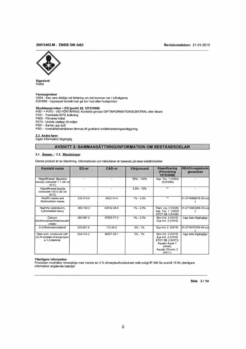
The supplier uses a corrosion protective oil named Houghton ENSIS DW 2462 as standard
for its customers. This oil is a mixture including paraffin and hydrocarbon waxes, naphtha
and calcium-sulphur compounds. [24] To better fit Scania process standards, the supplier
was instructed to use a different oil named DINOL Dinitrol 40, a purer oil based on naphtha.
[25] The supplier claims they have used Dinitrol 40 for all batches, as Scania demanded.
The process used at Scania Ferruform consists of six steps: cleaning, pre-welding, pre-
heating, welding, post-heating and ultrasound testing. The first step is to clean the contact
surface. The housing and axle ends are then pre-welded to each other for better alignment.
The pre-welding is done through creating a shallow weld over the entire joint, a process that
is much quicker than the actual welding. The process is then proceeding with the pre-heating
of the joint. The pre-heating is executed through induction heating at a specified
temperature. After this step, the weld is created using a 20kW CO2 laser. The weld is done
with an overlap of approximately 25mm. No groove, as well as no filler material, is used
during welding. Then the welded joint is post-heated through induction at a specified
temperature. After this step, the rear axle is put through ultrasound testing to find potential
defects in the weld.
3.2 Investigation methods
For the tests made in this report, the different samples examined were taken from the
untouched housing material, the pre-heated housing material and the welded joint from the
defective batch (delivery 2) and the good batch (delivery 3) respectively. The welded sample
from delivery 2 is referred to as 20x2 and the welded sample from delivery 3, x141. All the
samples were made from housing materials from the supplier as to compare the difference
between the defective and the approved welds from the same material composition. The
samples received from Scania were one piece of untreated housing material from the batch
where the defects had occurred, and a few samples of the two different welds. The pre-
heating treatment was done using the delivery condition metal piece.
The analyses made for this report are shown in figure 10. To analyse the steel samples, they
went through EDS analysis using a scanning electron microscope (SEM). The SEM used is a
Hitachi S-3700N. The EDS analysis is used to find the composition on the surface of the
samples. The corrosion protection oil composition was provided by the company Exova. The
analysis was done according to ASTM D5185 using inductively coupled plasma atomic
emission spectrometry (ICP-AES).

13
Figure 10: Explanative flow chart of samples examined and their order in the process.
3.3 Sample preparation
Four samples were cut out of the untreated delivery condition housing metal. Then two of
them were put in heat treatment. The heat treatment was performed using an oven, which
would give a good enough similarity to the heating used at Scania. The oven was preheated
with a piece of copper inside. The copper was used to make the heat transfer to the sample
faster, which would give a more similar process to induction heating. When the oven was
showing the temperature 670°C the samples were put on the copper piece and held in the
oven for approximately 5 seconds. The temperature was set to 670°C instead of 620°C
because of a known inaccuracy of 50°C in the equipment. This experiment was conducted to
be able to approximate which substances from the corrosion protection agent that would
evaporate during pre-heating. The samples were examined on the surface to see how the
surface elements changed during processing. The samples were put in SEM (scanning
electron microscope) to perform an EDS (energy dispersive spectroscopy) analysis to
determine the composition. The change in composition was then analysed which is discussed
later in this report.

14
4 Results
The results from EDS analysis of material samples, and from analysis of oil samples, are
shown in following paragraphs.
4.1 Oil analysis
The composition of the oil samples was analysed at Exova using the ASTM D5185 standard.
The results are shown in table 4.
Table 4: Results of chemical analysis made by Exova.
Element [mg/kg] Dinitrol 40 Houghton
Aluminium (Al) 330 3,47
Barium (Ba) 0,11 0,2
Iron (Fe) 2,97 6,43
Calcium (Ca) 8,66 3210
Silicon (Si) 2,21 4,25
Copper (Cu) 0,05 0,67
Chromium (Cr) 0,06 0,07
Magnesium (Mg) 0,78 18,9
Manganese (Mn) 0,18 0,56
Sodium (Na) 33 9,92
Sulphur (S) 5050 1570
Titanium (Ti) 0,58 0,26
Zinc (Zn) 1,41 0,95
The oils are shown to contain very small amounts of several elements. These elements are not
discussed further in this report. Large deviations are found between the two oils. The sulphur
content is three times higher in Dinitrol 40 compared to Houghton. Even larger differences
between the two samples can be found for aluminium and calcium which differs with a factor
of about 100 and 370 respectively. Other elements such as magnesium differs quite
significantly, but are still found only in small quantities.
4.2 EDS analysis of housing surface
Housing surfaces were analysed from different stages in the process. On the welded samples
the analysis was made a few mm from the FZ. An illustration of the area is demonstrated in
figure 11. Sample D2x1 is the housing sample analysed before heat treatment, D2x2 is after
heat treatment. Both samples are from delivery 2, but neither are welded. These analyses
were made to find if the corrosion protective coating would be affected by the heat treatment.
Sample 20x2 (delivery 2) and x141 (delivery 3) were both analysed post welding. Housings
from delivery 3 all gave good welds. X141 was analysed to compare delivery 2 to other
deliveries of housings. In table 5, all the results from surface analysis are shown.
15
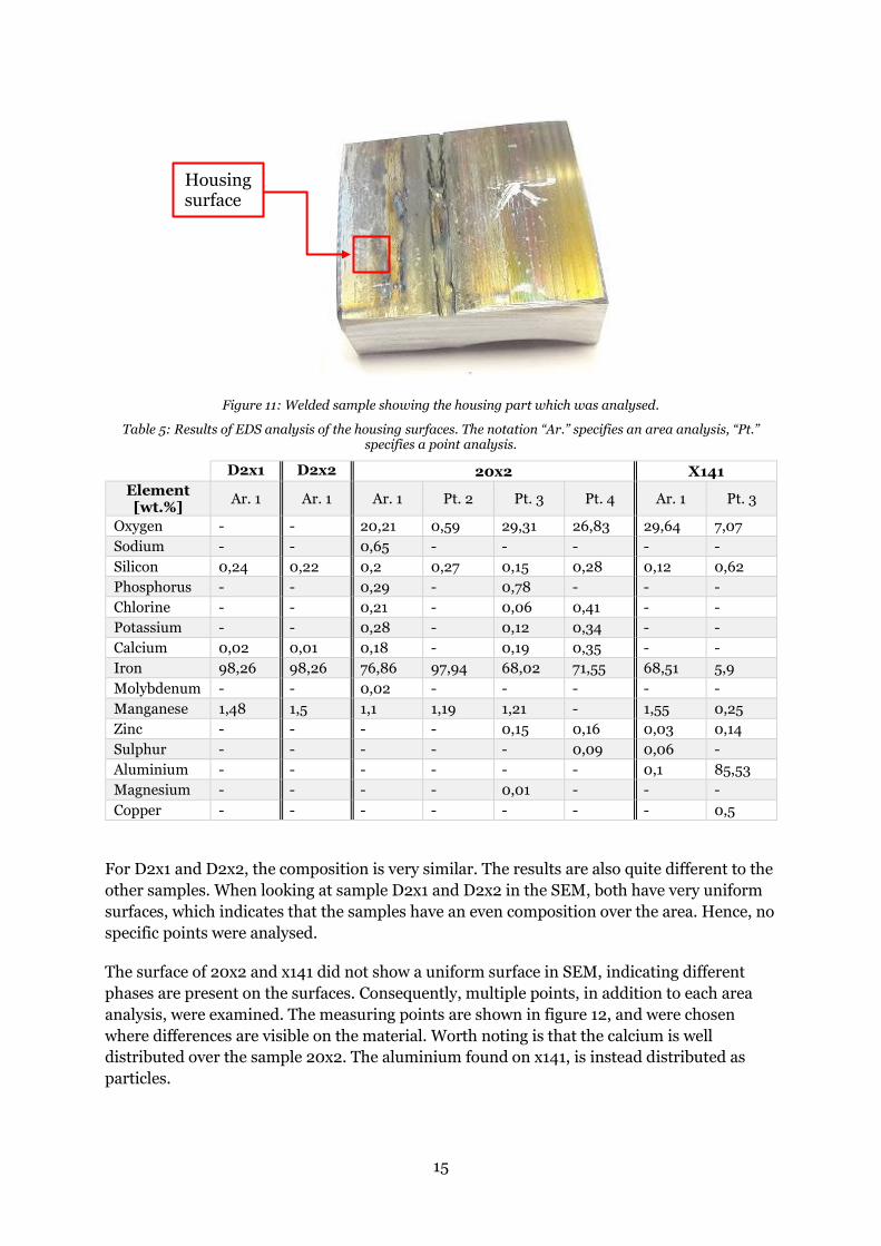
Figure 11: Welded sample showing the housing part which was analysed.
Table 5: Results of EDS analysis of the housing surfaces. The notation “Ar.” specifies an area analysis, “Pt.” specifies a point analysis.
D2x1 D2x2 20x2 X141
Element [wt.%]
Ar. 1 Ar. 1 Ar. 1 Pt. 2 Pt. 3 Pt. 4 Ar. 1 Pt. 3
Oxygen - - 20,21 0,59 29,31 26,83 29,64 7,07
Sodium - - 0,65 - - - - -
Silicon 0,24 0,22 0,2 0,27 0,15 0,28 0,12 0,62
Phosphorus - - 0,29 - 0,78 - - -
Chlorine - - 0,21 - 0,06 0,41 - -
Potassium - - 0,28 - 0,12 0,34 - -
Calcium 0,02 0,01 0,18 - 0,19 0,35 - -
Iron 98,26 98,26 76,86 97,94 68,02 71,55 68,51 5,9
Molybdenum - - 0,02 - - - - -
Manganese 1,48 1,5 1,1 1,19 1,21 - 1,55 0,25
Zinc - - - - 0,15 0,16 0,03 0,14
Sulphur - - - - - 0,09 0,06 -
Aluminium - - - - - - 0,1 85,53
Magnesium - - - - 0,01 - - -
Copper - - - - - - - 0,5
For D2x1 and D2x2, the composition is very similar. The results are also quite different to the
other samples. When looking at sample D2x1 and D2x2 in the SEM, both have very uniform
surfaces, which indicates that the samples have an even composition over the area. Hence, no
specific points were analysed.
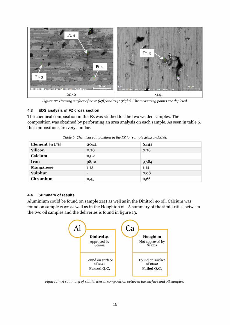
The surface of 20x2 and x141 did not show a uniform surface in SEM, indicating different
phases are present on the surfaces. Consequently, multiple points, in addition to each area
analysis, were examined. The measuring points are shown in figure 12, and were chosen
where differences are visible on the material. Worth noting is that the calcium is well
distributed over the sample 20x2. The aluminium found on x141, is instead distributed as
particles.
Housing surface
16
20x2 x141
Figure 12: Housing surface of 20x2 (left) and x141 (right). The measuring points are depicted.
4.3 EDS analysis of FZ cross section
The chemical composition in the FZ was studied for the two welded samples. The
composition was obtained by performing an area analysis on each sample. As seen in table 6,
the compositions are very similar.
Table 6: Chemical composition in the FZ for sample 20x2 and x141.
Element [wt.%] 20x2 X141
Silicon 0,28 0,28
Calcium 0,02 -
Iron 98,12 97,84
Manganese 1,13 1,14
Sulphur - 0,08
Chromium 0,45 0,66
4.4 Summary of results
Aluminium could be found on sample x141 as well as in the Dinitrol 40 oil. Calcium was
found on sample 20x2 as well as in the Houghton oil. A summary of the similarities between
the two oil samples and the deliveries is found in figure 13.
Dinitrol 40
Approved by Scania
Found on surface of x141
Passed Q.C.
AlHoughton
Not approved by Scania
Found on surface of 20x2
Failed Q.C.
Ca
Figure 13: A summary of similarities in composition between the surface and oil samples.
Pt. 3
Pt. 4
Pt. 3
Pt. 2

17
5 Discussion
Because of the investigations made at LTU, material properties are not believed to be the
cause of the welding problem. [2] The main defects relevant for this report are the large
porosities and undercuts in the weld, and how these defects correlated with the occurrence of
mid-section bulging in cross section. Since the reports from LTU focus on the occurrence of
micro cracks and non-metallic inclusions, much of LTU’s research is deemed irrelevant for
this report. The small cracks and inclusions are also present in welded Domex 420 housings
which have not caused problems in the past.
The test performed at Scania showed some differences when different parts of the surface
were removed. This led to the belief that the welding defects are linked to the surface of the
housings. When only the root was lathed, the defects still occurred, but when the root and the
adjacent surfaces were removed, the defects did not appear in FZ. Because it is known that
the housings are treated with anti-corrosive oil, investigations had to be made to find its
possible correlation to welding defects. At Ferruform, it was noticed that delivery 2 had a
different texture on the surface. The surface seemed to have a more wax-like surface,
compared to the oil-like texture of other deliveries. It was known the outsourced supplier
often used an anti-corrosive oil called Houghton for its other costumers, which contains a
small amount of paraffin. The paraffin in the Houghton oil could be a possible explanation to
why the housings from delivery 2 have a wax-like surface.
5.1 Results of EDS- and oil analysis
The results from EDS of the metal samples, as well as chemical analysis of the oil samples are
discussed in the following paragraphs.
5.1.1 D2x1 and D2x2 – housing material before welding
The samples of the housing material before welding gave the same composition results on the
surface and the cross section. It is apparent that no corrosion protection agents can be found
on the surface.
5.1.2 Oil analysis
The main objective when analysing the oils were to compare chemical compositions and by
doing so, find something in the Houghton oil that could lead to instabilities in the weld. The
analysis showed, as can be seen in table 4, a large difference between the two oils. There were
also major differences in the oil base. According to the data sheets (appendix B-D), Houghton
oil contains paraffin opposed to the pure naphtha base of Dinitrol 40. This should in theory
make it more difficult to remove the Houghton oil from the surface, leaving residues affecting
weld quality.
Assumed that some oil residues remained on the housing surface during welding entails
hydrocarbons will be present, as well as some organic substances. Research was done to find
material on how this could affect the weld, but no sources were found on this subject. The
sources found only mentioned the importance of having a clean environment for the process
of laser welding, but did not mention what happens when the weld is contaminated.
The choice was made to investigate if any of the elements in the Houghton oil could have had
an impact on the weld. The large quantity elements in the Houghton oil are calcium, sulphur,
magnesium and sodium. The vast amount of calcium can be explained in the data sheet due

18
to the amount of calciumsulfonate in the oil. Calciumsulfonate has the molecular formula
C56H86CaO6S2 which may also explain the high sulphur content. [26] The high sulphur content
could possibly impact the weld if it is dissolved in the weld metal, but according to EDS
analysis in table 6, this is not the case.
5.1.3 20x2 and x141 – welded samples
Interestingly, surfaces of 20x2 and x141 welded samples differs quite significantly. On sample
x141 small phases consisting of almost pure aluminium were found, this was not the case with
20x2. On 20x2 phases consisting of a sodium, phosphor, chlorine etc. were observed. Most
interesting is the findings of calcium. Impurities like sodium, chlorine and silicon could
possibly be a result when handling the samples. Salts from the hands and dust could have
contaminated the samples before analysis since extensive cleaning was not made to keep
samples intact. [27]
The calcium findings are harder to explain since this is not a common element in our
surroundings. Since calcium is found in large quantities in the Houghton oil, this is the main
argument to why the wrong oil may have been used by the supplier. Furthermore, aluminium
is found in Dinitrol 40 as well as on the surface of x141. If the same corrosion protection oil
had been used, surface appearance should be the same.
5.2 Possible similarities between zinc- and calcium-coating
The hypothesis that Houghton oil has been used by the supplier would result in a thin layer of
calcium on the housing. Because of the low vaporisation temperature of calcium, 1482 ˚C
(close to the melting point for steel [28]), it may be possible calcium will show the same
behaviour as zinc during laser welding. Since operation temperature inside the keyhole is
around 3000 K, calcium will vaporise. This is also an explanation to why calcium can be
found on the surface of the housing but not in welded metal, following the zinc behaviour.
[20] Axle ends and housing is welded without a groove in between, making it harder for gases
created during the process to escape, leading to higher keyhole pressure and thus enlarging
it. As described by Y. Pan an enlarged keyhole due to CO creation will lead to greater
penetration depth. This could explain why severe undercuts as well as burn through can be
observed in affected welds.
The predictably uneven layer of corrosion protective oil may also contribute to uneven
keyhole pressure due to uneven vaporisation. An uneven gas flow creates keyhole oscillations
as described by Y. Pan, causing keyhole collapse and defects.
During the testing at Scania, trials were made where only the root of the weld was removed
without any improvements in weld quality. The reason why results from these trials differ to
such large extent compared to when all adjacent surfaces was removed is unknown. One
could argue that by removing the root surfaces, only a fraction of the metal with corrosion
protection coating would be exposed to high temperature. Also, potential gases should be
able to easily escape. One explanation to why this did not decrease the number of defects,
could be that molten flow is large enough to bring the corrosion protection coating down into
the melt pool before it vaporises, leading to the same type of defects as before.

19
5.3 Focal point and weld geometry
Rear axle welds from delivery 2 sometimes showed altered cross section geometry. The
reason behind this is still unclear. Furthermore, the appearance of mid-section bulges in
conjunction with the welding defects cannot be explained.
The only way to obtain a wider weld, if welding parameters are constant is by increasing heat
absorption efficiency. The keyhole dynamics are coupled with many different properties and
parameters making it difficult to find a single explanation to the origin of these defects.
It is known that the focal point of the laser beam is related to melt flow and thereby heat
conduction. An altered focal point could in theory therefore affect defects like those observed
in this case. [18] But since process parameters were not changed this is not a plausible
explanation. The outcome of this study is that no conclusions could be drawn regarding the
mid-section bulging defect.
5.4 Sources of error
Problems could have occurred during the analysis of the samples. Zinc and sodium have very
similar spectrums when measuring through EDS analysis which could have led to a
misinterpretation of the measurements. Initially it was assumed that the surface was more
likely to contain zinc than sodium, but after it was discovered that the surface included
chlorine in the same measuring points where sodium was found it seems more likely that it
could be salt contaminations on the sample after handling it bare handed.
The sample could also have been contaminated with dust from the environment and it is
therefore likely that the measurements might differ from the actual compositions. When
considering these kinds of error sources, it is important to note that all the samples are
handled in the same way and it could be argued that some traces of contamination should be
found on most sample surfaces.
The SEM could also be the wrong method to use when examining these samples. The oils
might partly evaporate due to the low pressure in the microscope and they could also have
disappeared due to the thorough cleaning of the samples before analysing them. The cleaning
was necessary to use the equipment because otherwise the microscope could be damaged.

20
6 Conclusion
• Neither the material properties nor the parameters of the welding process are
probable causes for the defects found in the rear axle welds at Scania. It is very likely
that the corrosion protection, used in delivery 2, is different from what Scania
specified.
• Aluminium found in Dinitrol 40, specified to be used by Scania, was found on the
welded axle housing which past quality control. Calcium was found in Houghton as
well as on the housing surface not passing quality control.
• The reason for the porosities in the welded material shows a strong relation to the
surface of the material, and the only noticeable differences between good and bad
batches are the differences in appearance of the corrosion protection coating.
• The investigations made for this report are not sufficient to determine how the anti-
corrosive agent have affected the weld.

21
7 Further investigations
This report does not find a strict conclusion as to why the rear axle welds turned out badly.
Furthermore, it is recommended to perform further research in this area. One aspect that
should be examined is if the surface of the housing pieces studied in this report could have
been too clean before the analysis commenced. If that is the case, the surface would have to
be examined again. One method that could work better for the samples in this report could be
X-ray fluorescence (XRF) which is a method that does not require vacuum and therefore
would not harm the samples. [29]
Another test that could give important information is to try and put a groove between the axle
end and the housing and see if the weld still turns out defective. By using a groove, the
chances are reduced that the gas would be trapped in the weld and it is less likely that the
large porosities would occur.

22
8 Acknowledgements
We would like to thank or supervisor Anders Eliasson, KTH Royal Institute of Technology,
material science, for guiding us through this project and helping us interpret our results. We
would also like to thank our supervisors from Scania Södertälje - Materials Technology R&D
(YTMR), Erik Tolf and Scania Ferruform AB – DLER, Luleå, Mikael Juntti. Lastly, we want to
send our thanks to Wenli Long at KTH Royal Institute of Technology, who gave us much time
and a lot of her expertise when we made our analyses in the SEM.
23
9 References
[1] ”gowelding,” [Online]. Available: http://www.gowelding.org/articles/history-of-welding/. [Använd 24 may 2017].
[2] P. Rosa och V. Esa, ”Defects after laser welding of a structural steel,” Luleå University of Technology, Luleå, 2016.
[3] B. Bergman och M. Sellby, Materiallära för Materialdesign, Sweden: US-AB, 2015.
[4] B. Åhgren, ”Seghärdat stål - Starkt, segt, svetsbart,” Väg- och vattenbyggaren, nr 2, pp. 20-22, 1988.
[5] Swerea IWF, ”Seghärdningsstål,” i Stål och Värmebehandling - en handbok, Mölndal, Swerea IWF, 2010, pp. 38-43, 218-227.
[6] ”Steelnumber,” [Online]. Available: http://www.steelnumber.com/en/steel_composition_eu.php?name_id=194. [Använd 27 april 2017].
[7] ”SSAB Domex 420MC,” [Online]. Available: http://www.ssab.se/produkter/varumarken/ssab-domex-konstruktionsstal/products/ssab-domex-420mc. [Använd 27 2 2017].
[8] ”S460N,” [Online]. Available: http://www.steelnumber.com/en/steel_composition_eu.php?name_id=22. [Använd 27 2 2017].
[9] ”S460N steel plate,” [Online]. Available: http://www.tritonalloysinc.com/en-10025-s460-steel/steel-plate-bs-en-10025-grade-s460-plate/steel-plate-type-bs-en-10025-grade-s460-plate/. [Använd 31 3 2017].
[10] ”EN10025-3 S460N Carbon and Low-alloy High-strength Steel Plate,” [Online]. Available: http://www.steel-plate-sheets.com/steelgrade/EN10025-3-S460N-Carbon-and-Low-alloy-High-strength-Steel-Plate-en.html . [Använd 31 3 2017].
[11] ”EN 10025-3 S460N High Yield Strength Steel Plate,” [Online]. Available: http://www.steel-plate-sheet.com/Sellinglist/EN-100253-S460N-High-Strength-Steel-Plate.html . [Använd 31 3 2017].
[12] D. A. Hijazi, ”eis.hu.edu.jo,” [Online]. Available: https://eis.hu.edu.jo/ACUploads/10526/Intro%20to%20Welding%20Technology.pdf. [Använd 27 april 2017].
[13] K. Weman, i Svetshandbok, Göteborg, Liber, 1997, p. 141.
[14] S. Katayama, Handbook of Laser Welding Technologies, Woodhead Publishing, 2013, pp. 332-369.
[15] J. Eastman, ”EWI.org,” 20 february 2015. [Online]. Available: https://ewi.org/conduction-mode-vs-keyhole-mode-laser-welding/. [Använd 28 april 2017].
[16] W. Tan och Y. C. Shin, ”Analysis of multi-phase interaction and its effects on keyhole dynamics with a multi-physics numerical model,” Journal of Physics , vol. 47, nr 34, 2014.
[17] J. Svenungssona, I. Choqueta och A. F. H. Kaplan, ”Laser welding process – a review of keyhole welding modelling,” i 15th Nordic Laser Materials Processing Conference, 2015.
[18] B. J. Aalderink, D. F. d. Lange, R. G. K. M. Aarts och J. Meijer, ”Keyhole shapes during laser welding of thin metal sheets,” Journal of Physics D: Applied Physics, vol. 40, nr 17, pp. 5388-5393, 2007.
[19] Visual Labs, http://mm-coep.vlabs.ac.in/LaserSpotWelding/Theory.html?domain=Mechanical%20Engineering&lab=Welcome%20to%20Micromachining%20laboratory.
[20] Y. Pan och I. M. Richardson, ”Keyhole behavior during laser welding of zinc-coated steel,” Journal of Physics D: Applied Physics, vol. 44, nr 4, pp. 1-11, 2011.
[21] S. T. R. R. T. D. B. Ribic, ”Role of surface-active elements during keyhole-mode laser welding,” Journal of Physics D: Applied Physics, vol. 44, nr 48, pp. 1-10, 2011.
[22] M. M. S. K. Yasuaki Naito, ”Effect of oxygen in ambient atmosphere on penetration characteristics in single yttrium–aluminum–garnet laser and hybrid welding,” Journal of Laser Applications, vol. 18, nr 1, pp. 21-27, 2006.

24
[23] Z. L, T. S, A. G, S. T och D. T, ”Influence of oxygen on weld geometry in fibre laser and fibre laser–GMA hybrid welding,” Science and Technology of Welding and Joining, vol. 16, nr 2, pp. 166-173, 2011.
[24] Houghton, ”Shell,” 21 januari 2015. [Online]. Available: http://shell.univarlubricants.se/wp-content/uploads/2016/04/HOUGHTON-ENSIS-DW-2462_SDS_SE.pdf. [Använd 27 april 2017].
[25] dinitroldirect, "Dinitroldirect," [Online]. Available: https://www.bigbrandsupport.com/DOWNLOADS/DINITROL/TDS/Corrosion-protection/Industrial/additional/Dintirol-40/dinitrol-40-TDS.pdf. [Accessed 27 april 2017].
[26] ”alfa-chemistry,” [Online]. Available: http://www.alfa-chemistry.com/calcium-bis-dinonylnaphthalenesulphonate-cas-57855-77-3-item-184204.htm. [Använd 11 may 2017].
[27] I. K. Anders Eliasson, Interviewee, meeting. [Intervju]. 10 may 2017.
[28] ”knowledgedoor,” [Online]. Available: http://www.knowledgedoor.com/2/elements_handbook/vapor_pressure.html. [Använd 28 april 2017].
[29] ”bruker,” [Online]. Available: https://www.bruker.com/products/x-ray-diffraction-and-elemental-analysis/handheld-xrf/s1-titan-series/overview.html. [Använd 23 may 2017].

i
Appendix A
EDS analysis of samples D2x1 and D2x2
A B
Figure 1: A) Surface of sample D2x1. B) Surface of sample D2x2.
Table 1: EDS analysis of D2x1 and D2x2.
Element [wt.%] Surface D2x1 Surface D2x2
Silicon 0,24 0,22
Calcium 0,02 0,01
Iron 98,26 98,26
Manganese 1,48 1,5
EDS analysis of welded samples
X141 cross section
A B C
Figure 2: A) The FZ of sample x141. B) The housing material. C) The axle end material.
Table 2: EDS analysis of the x141 welded cross section
Element [wt.%] Area 1 Area 2 Area 3
Silicon 0,28 0,18 0,2
Iron 97,84 98,26 96,6
Manganese 1,14 1,56 1,21
Sulphur 0,08 - 0,18
Aluminium - - 0,13
Chromium 0,66 - 1,45
Copper - - 0,24

ii
X141 housing surface after welding
A B
Figure 3: A) Area of housing surface on sample x141. B) Measuring points on housing surface of sample x141
Table 3: EDS analysis of x141 housing surface after welding
Element [wt.%] Area 1 Point 3 Point 4
Oxygen 29,64 7,07 -
Silicon 0,12 0,62 1,89
Iron 68,51 5,9 97,69
Manganese 1,55 0,25 0,42
Zinc 0,03 0,14 -
Sulphur 0,06 - -
Aluminium 0,1 85,53 -
Copper - 0,5 -
X141 FZ surface
A B
Figure 4: A) Area of FZ surface on sample x141. B) Measuring point used on FZ surface of sample x141.

iii
Table 4: EDS analysis of x141 FZ surface.
Element [wt.%] Area 5 Point 7
Oxygen 29,06 0,46
Silicon 0,13 0,19
Chlorine 0,07 -
Calcium 0,05 -
Iron 70,41 97,79
Manganese - 1,56
Zinc 0,1 -
Aluminium 0,05 -
Chromium 0,13 -
Defective 20x2 housing surface
A B
Figure 5: A) Area analysis of sample 20x2 housing surface. B) Measuring points used on sample 20x2 housing surface.
Table 5: EDS analysis of the EGE housing surface after welding.
Element [wt.%]
Area 1 Point 2 Point 3 Point 4 Point 5 Point 6
Oxygen 20,21 0,59 29,31 26,83 19,66 21,69
Sodium 0,65 - - - - -
Silicon 0,2 0,27 0,15 0,28 0,22 0,07
Phosphorus 0,29 - 0,78 - 0,08 0,3
Chlorine 0,21 - 0,06 0,41 0,4 -
Potassium 0,28 - 0,12 0,34 0,48 0,26
Calcium 0,18 - 0,19 0,35 0,22 0,13
Iron 76,86 97,94 68,02 71,55 78,72 75,73
Molybdenum 0,02 - - - 0,12 -
Manganese 1,1 1,19 1,21 - - 1,65
Zinc - - 0,15 0,16 0,09 0
Sulphur - - - 0,09 - -
Aluminium - - - - - 0,19
Magnesium - - 0,01 - - -
iv
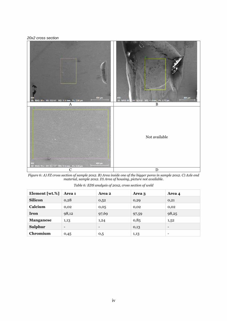
20x2 cross section
A B
Not available
C D
Figure 6: A) FZ cross section of sample 20x2. B) Area inside one of the bigger pores in sample 20x2. C) Axle end material, sample 20x2. D) Area of housing, picture not available.
Table 6: EDS analysis of 20x2, cross section of weld
Element [wt.%] Area 1 Area 2 Area 3 Area 4
Silicon 0,28 0,52 0,29 0,21
Calcium 0,02 0,05 0,02 0,02
Iron 98,12 97,69 97,59 98,25
Manganese 1,13 1,24 0,85 1,52
Sulphur - - 0,13 -
Chromium 0,45 0,5 1,13 -
v
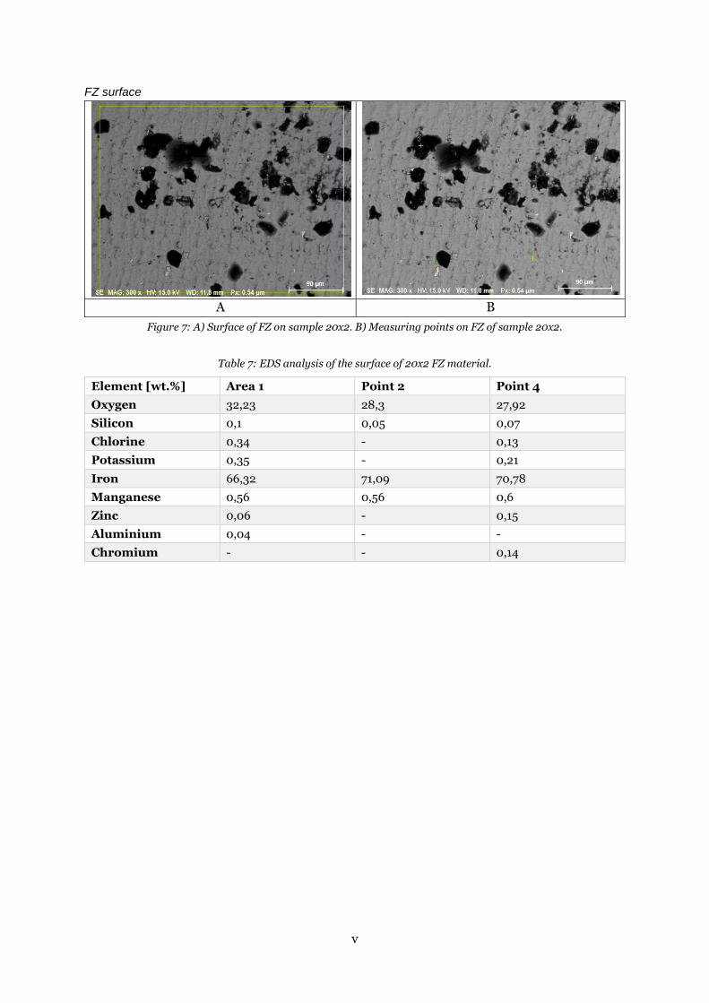
FZ surface
A B
Figure 7: A) Surface of FZ on sample 20x2. B) Measuring points on FZ of sample 20x2.
Table 7: EDS analysis of the surface of 20x2 FZ material.
Element [wt.%] Area 1 Point 2 Point 4
Oxygen 32,23 28,3 27,92
Silicon 0,1 0,05 0,07
Chlorine 0,34 - 0,13
Potassium 0,35 - 0,21
Iron 66,32 71,09 70,78
Manganese 0,56 0,56 0,6
Zinc 0,06 - 0,15
Aluminium 0,04 - -
Chromium - - 0,14
i
Appendix B

ii

i
Appendix C
i
Appendix D
ii

iii

iv
www.kth.se