definition nextreturn i. beams 1. definition a beam is a long, slender structural member generally...
TRANSCRIPT
Definition
< Next > < Return >
I. Beams
1. Definition A beam is a long, slender structural member generally subjected to transverse loading that produces significant bending effects (transverse displacement rotation).

< Prev > < Next > < Return >
Simple beam theory 1
)(
02
)(
0
)(0)()(
0
2
2 xwdxMd
VdxdMordxwdxVdxMdMM
Mmepuilibriumoment
xwdxdVordxxwdVVV
FmepuilibriuForce
A
y
2. Simple beam theory. Assumptions: (A)member cross section is constant.
(B)cross section dimension < overall length. (L/ t>10)
(C) linear variation of stress and strain.(Small deformation theory)
)/(:)(
:
)(:
:
:
lengthforceloadingddistributexw
momentbendingM
transverseforceShearV
rotationorslape
ntdisplacemelateralv
Equilibrium equation of a differential element of the beam.
Beam under distributed load
Differential beam element

< Prev > < Next > < Return >
Simple beam theory 2
For constant EI and only nodal forces and moments, equation becomes
Solution of displacement v(x) is of cubic polynomial function of x
)()( 2
2
2
2
2
2
xwdxvdEI
dxd
dxMd
04
4
dx
vdEI
2
21
dx
vd
EI
Mk
dx
dv Curvature of the beam for small slope is given by k
: radius of deflected curve.
E: modulus of elasticity.
I: principal moment of inertia about Z-axis
43
2
2
3
1)( axaxaxaxv
< Prev > < Next > < Return >
Beam element stiffness formulation 1
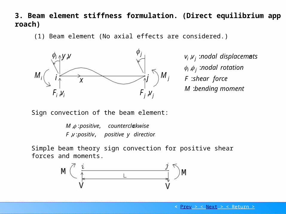
3. Beam element stiffness formulation. (Direct equilibrium approach) (1) Beam element (No axial effects are considered.)
momentbendingM
forceshearF
rotationnodal
ntsdisplacemenodalvv
ji
ji
:
:
:,
:,
Sign convection of the beam element:
directionypositivepositivvF
ckwisecounterclopositiveM
,:,
,:,
i j
jMiM i j
jj vF ,ii vF ,
x
vy,
Simple beam theory sign convection for positive shear forces and moments.
< Prev > < Next > < Return >
Beam element stiffness formulation 2
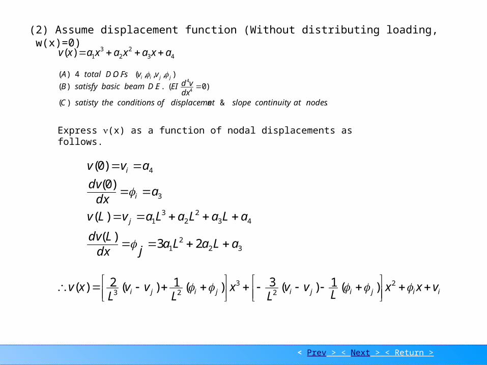
(2) Assume displacement function (Without distributing loading, w(x)=0)
432
23
1)( axaxaxaxv
Express (x) as a function of nodal displacements as follows.
322
1
432
23
1
3
4
23)(
)(
)0(
)0(
aLaLajdx
Ldv
aLaLaLavLv
adx
dv
avv
j
i
i
),,,(..4)( jjii vvFsODtotalA )0(..)( 4
4
dxvdEIEDbeambasicsatisfyB
.&)( nodesatcontinuityslopentdisplacemeofconditionsthesatistyC
iijijijiji vxxL
vvL
xL
vvL
xv
2
23
23 )(1)(3)(1)(2)(

< Prev > < Next > < Return >
Beam element stiffness formulation 3
j
j
i
i
v
v
NNNNdNv
4321 ,,,
.:,,, 4321 elementbeamaforfunctionsshapeNNNN
223
3423
33
322332
32331
1,321
21,321
xLLxL
NLxxL
N
xLLxLxL
NLLxxL
N
In matrix form, we have
< Prev > < Next > < Return >
Beam element stiffness formulation 4
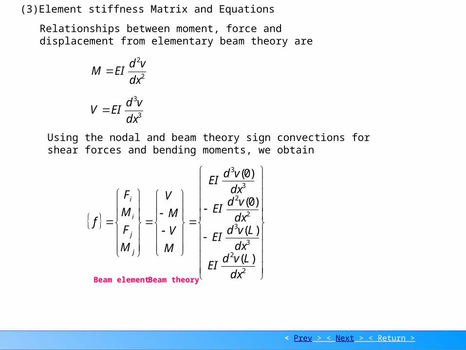
(3)Element stiffness Matrix and Equations
Relationships between moment, force and displacement from elementary beam theory are
Using the nodal and beam theory sign convections for shear forces and bending moments, we obtain
2
2
dx
vdEIM
2
2
3
3
2
2
3
3
)(
)(
)0(
)0(
dxLvd
EI
dxLvd
EI
dxvd
EI
dxvd
EI
M
V
M
V
M
F
M
F
f
j
j
i
i
3
3
dx
vdEIV
Beam element Beam theory

< Prev > < Next > < Return >
Beam element stiffness formulation 5
Hence, the beam element equation relating nodal forces and nodal displacements is given as
j
j
i
i
j
j
i
i
v
v
LLLL
LL
LLLL
LL
LEI
M
F
M
F
22
22
3
4626
612612
2646
612612
LLLdx
Nd
LLxLxLLxLxLdx
Nd
ddx
Nd
dxvdd
dx
Nd
dxvdd
dxNd
dxdv
dNv
6,12,6,121
)26(),612(),46(),612(1
,,
33
3
2232
2
3
3
3
3
2
2
2
2
Use the following equations into above equation.
dkfor
Where [k] is the element stiffness matrix for a beam element with neglected axial effects.

< Prev > < Next > < Return >
Example 1
4. Example:
j
j
i
i
M
F
M
F
L
L
LLL
LL
L
EIKK
2
22
3
)2()1(
4
612
264
612612
By direct stiffness method,the system eqn. For the beam is obtained as
EI ConstantP
3
3
2
2
1
1
2
222
22
3
3
3
2
2
1
1
4
612
2644
612661212
00264
00612612
v
v
v
L
L
LLLL
LLL
LLL
LL
L
EI
M
F
M
F
M
F
y
y
y
0,0,:,0: 211332 MMPFloadsvvconditionsBoundary y
0
0
0
4
612
2644
612661212
00264
00612612
0
0
2
1
1
2
222
22
3
3
3
2
v
L
L
LLLL
LLL
LLL
LL
L
EI
M
F
F
P
y
y
< Prev > < Next > < Return >
Example 1
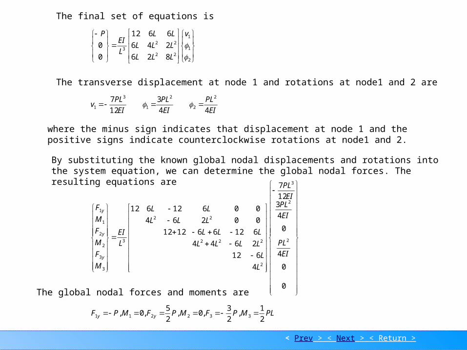
The final set of equations is
2
1
1
22
223
826
246
6612
0
0
v
LLL
LLL
LL
L
EIP
The transverse displacement at node 1 and rotations at node1 and 2 are
EI
PL
EI
PL
EI
PLv
44
3
12
7 2
2
2
1
3
1
where the minus sign indicates that displacement at node 1 and the positive signs indicate counterclockwise rotations at node1 and 2.
By substituting the known global nodal displacements and rotations into the system equation, we can determine the global nodal forces. The resulting equations are
0
0
4
0
4
312
7
4
612
2644
612661212
00264
00612612
2
2
3
2
222
22
3
3
3
2
2
1
1
EI
PL
EI
PLEI
PL
L
L
LLLL
LLL
LLL
LL
L
EI
M
F
M
F
M
F
y
y
y
The global nodal forces and moments are
PLMPFMPFMPF yy 2
1,
2
3,0,
2
5,0, 332211

< Prev > < Next > < Return >
Example 2
Local nodal force for each element (used for stress analysis of the entire structure)
2
2
3
2
3
3
3
2
2
)2(
3
3
2
2
2
PL
P
PL
P
y
y
v
v
K
m
f
m
f
Element
PL
P
P
v
v
k
m
f
m
f
y
y
Element
0
2
2
1
1
)1(
2
2
1
1
1
P2
3
P
P
PL PL2
PLP
2
3
Free body diagrams for element 1 and 2 are shown as follows.
According the results of the global nodal forces and moments, the free body diagram for the whole beam is given as shown.
12
3 2
PL
P2
3
P2
5P
< Prev > < Next > < Return >
Example 3
1 2 3
P2
3
P
M
1 2 3
PL
2
PL
V
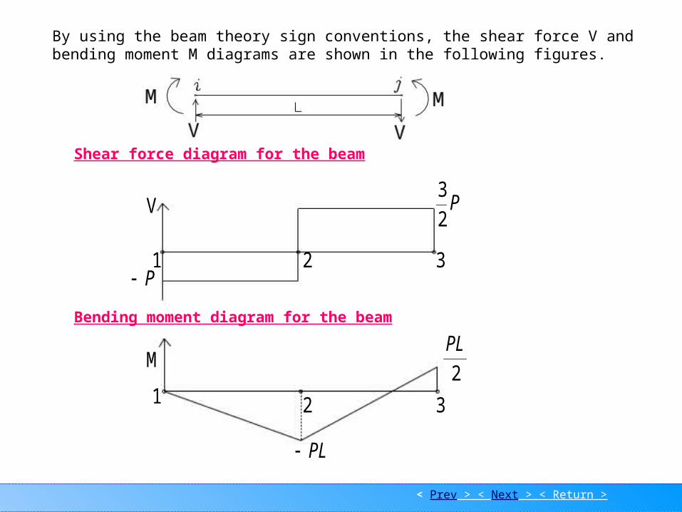
Shear force diagram for the beam
Bending moment diagram for the beam
By using the beam theory sign conventions, the shear force V and bending moment M diagrams are shown in the following figures.

< Prev > < Next > < Return >
Distributed loading
5. Distributed loading Equivalent force system:
Replace the distributed load by concentrated nodal forces and moments tending to have the same effect on the beam as the actual distributing load based on the concept of fixed-end reactions from structural analysis theory.
w
y
1F 2F1M 2M
x
Ex. Distributed load. equivalent force system
w
w
12
2wL12
2wL2
wL
2
wL
30
2wL12
2wL20
3wL
20
7wL
Fixed-end reactions are those reactions at the ends of an element if the ends of the element are assumed to be fixed.
Beam subjected to a distributed load Fixed-end reactions for the beam
< Prev > < Next > < Return >
Dis EX 1
eM1
eF1
2
wL
12
2wL
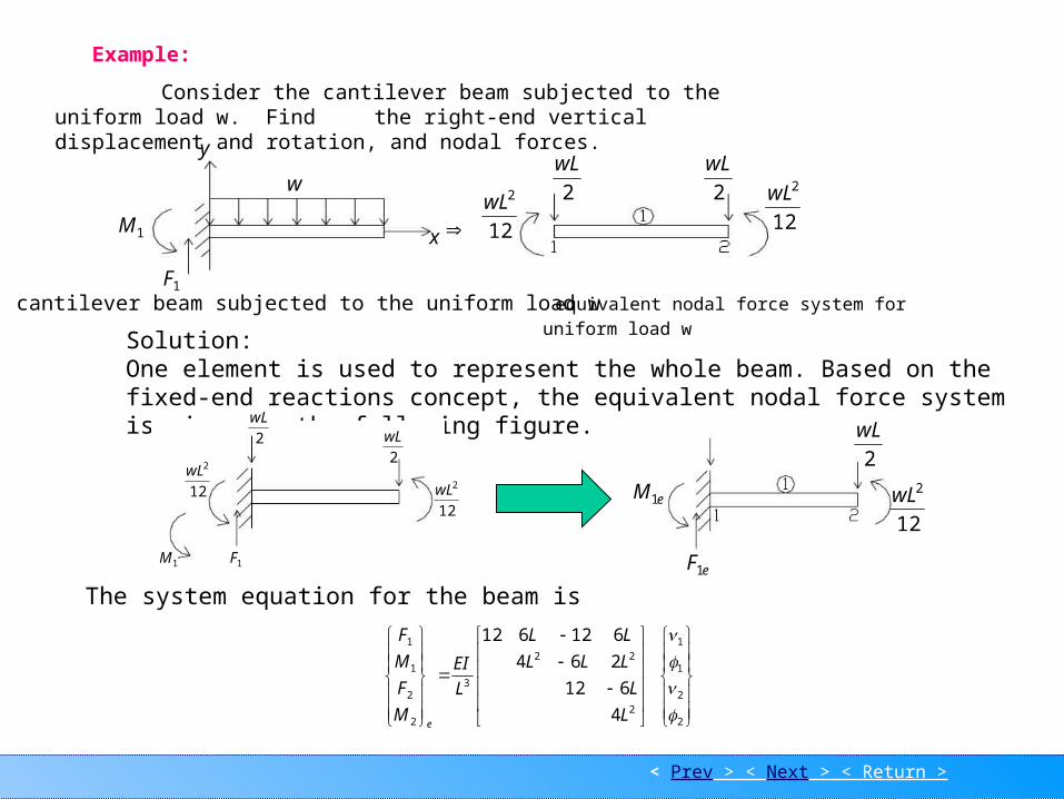
Example:
Consider the cantilever beam subjected to the uniform load w. Find the right-end vertical displacement and rotation, and nodal forces.
equivalent nodal force system for uniform load
w
2
2
1
1
2
22
3
2
2
1
1
4
612
264
612612
L
L
LLL
LL
L
EI
M
F
M
F
e
1M
1F
y
w
x 12
2wL 2
wL
2
wL
12
2wL
cantilever beam subjected to the uniform load w
Solution:One element is used to represent the whole beam. Based on the fixed-end reactions concept, the equivalent nodal force system is given as the following figure.
The system equation for the beam is
12
2wL
1M 1F
2
wL
12
2wL
2
wL
< Prev > < Next > < Return >
Dis EX 1
6
8
12
263
326
3
2
2
2
2
w
wL
EIL
wL
wL
L
LLEIL
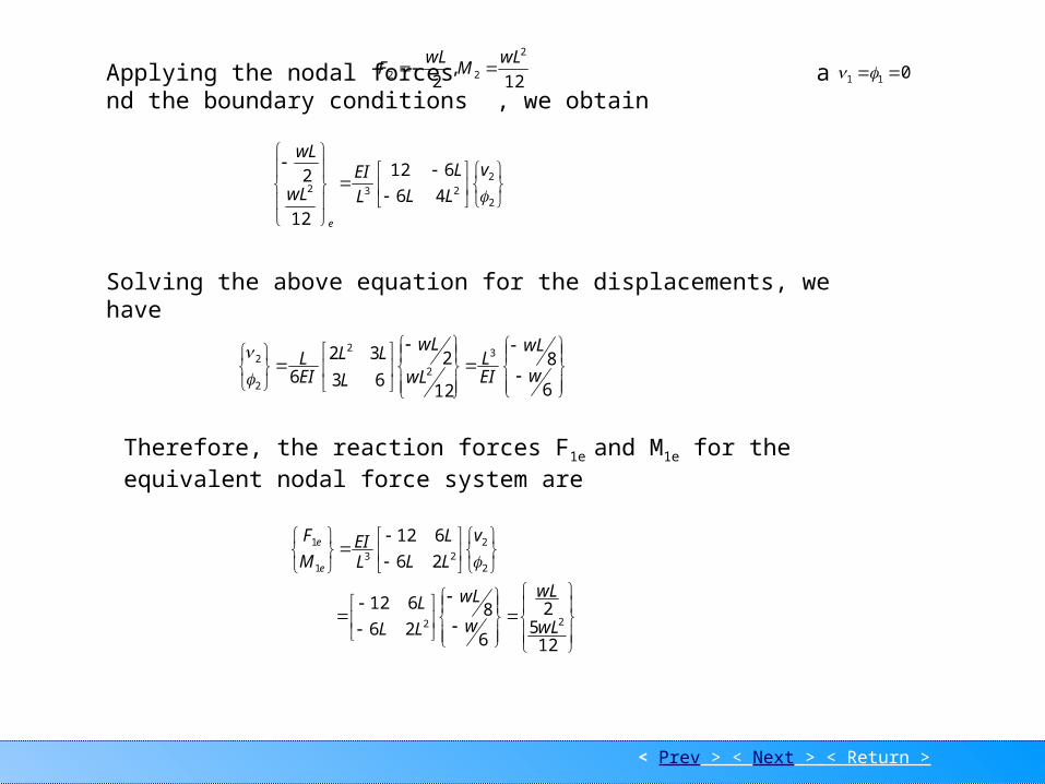
Applying the nodal forces and the boundary conditions , we obtain
12,
2
2
22
wLM
wLF 011
2
2
23246
612
12
2v
LL
L
L
EIwL
wL
e
Solving the above equation for the displacements, we have
Therefore, the reaction forces F1e and M1e for the equivalent nodal force system are
125
2
6
826
612
26
612
22
2
2
231
1
wL
wL
w
wL
LL
L
v
LL
L
LEI
M
F
e
e

< Prev > < Next > < Return >
Dis EX 2
The equivalent nodal forces are
12/
2/
12/
2/
2
2
0
wL
wL
wL
wL
F
Hence, the effective global nodal forces are
EIwL
EIwL
L
L
LLL
LL
LEI
wL
wL
wL
wL
M
F
M
F
F
e
e
e
e
e
6/
8/
0
0
4
612
264
612612
12/
2/
12/5
2/
3
4
2
22
3
2
2
2
2
1
1
Thus, the correct global nodal forces
0
0
2/2
0
wL
wL
FFF e
eMwL
M 1
2
1 12
By comparing the two equivalent system given in the previous page, we have relationships among the correct nodal forces, the effective nodal forces and the equivalent nodal forces.
eFwL
F 11 2

< Prev > < Next > < Return >
Bar Element 1
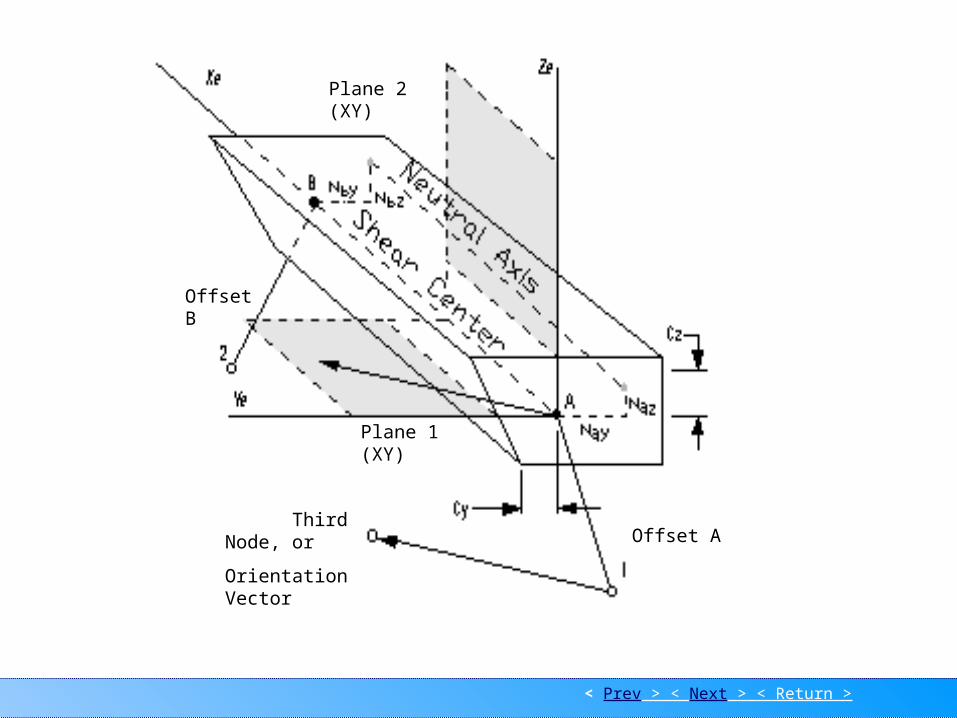
DescriptionUniaxial element with tension, compression, torsion, and bending capabilities. The more general Beam element is often used instead of this element. The figure, at the end of this section, defines both element types. For some analysis programs, MSC/N4W translates both types to the same element type.
Application Used to model general beam/frame structures.
Shape Line, connecting two nodes. A third node can be specified to orient the element Y axis.
Element Coordinate System The element X axis goes from the first node to the second.The element Y axis is perpendicular to the element X axis. It points from the first node toward the orientation (or third) node. If you use an orientation vector, the Y axis points from the first node in the direction of the orientation vector. The element Z axis is determined from the cross product of the element X and Y axes.
Properties Area, Moments of Inertia (I1, I2, I12), Torsional Constant, Shear Areas (Y, Z), Nonstructural Mass/Length, StressRecovery Locations.
Additional Notes Refer to the Beam element for further descriptions regarding Releases, Offsets and Stress Recovery Locations.
Bar Element
< Prev > < Next > < Return >
Bar Element 2
Third Node, or
Orientation Vector
Plane 1 (XY)
Offset A
Offset B
Plane 2 (XY)

< Prev > < Next > < Return >
Beam Element 1
Description
Uniaxial element with tension, compression, torsion, and bending capabilities. This element can be tapered. You can specify different properties at each end of the beam.
Application
Used to model beam/frame structures.
Shape
Line, connecting two nodes. A third node can be specified to orient the element Y axis.
Element Coordinate System
The element X axis goes from the first node to the second. The element Y axis is perpendicular to the element X axis. It points from the first node toward the orientation (or third) node. If you use an orientation vector, the Y axis points from the first node in the direction of the orientation vector. The element Z axis is determined from the cross product of the element X and Y axes.
Properties
Area, Moments of Inertia (I1, I2, I12), Torsional Constant, Shear Areas (Y, Z), Nonstructural Mass/Length, Stress Recovery Locations, Neutral Axis Offsets (Nay, Naz, Nby and Nbz). If the beam is tapered, you can specify different properties at each end of the element.
Additional Notes
You can specify Releases which remove the connection between selected element degrees of freedom and the nodes.
Offset vectors defined on the Element move the neutral axis and shear center from the nodes. Neutral Axis Offsets (Y,Z) defined on the Property card move the neutral axis away from the shear center. If there are no Neutral Axis Offsets, the neutral axis and shear center are coincident.
Beam Element

< Prev > < Next > < Return >
Beam Element 2
Third Node, or
Orientation Vector
Plane 1 (XY)
Offset A
Offset B
Plane 2 (XY)
If there are no offsets,both the neutral axis and shear center lie directly between the nodes.
Stress Recovery Locations define positions in the elemental YZ plane (element cross-section) where you want the analysis program to calculate stresses.
Specifying moments of inertia for Beam (and Bar) elements can sometimes be confusing. In MSC/N4W, I1 is the moment of inertia about the elemental Z axis. It resists bending in the outer Y fibers of the beam. It is the moment of inertia in plane 1. Similarly, I2 is the moment of inertia about the elemental Y axis. If you are familiar with one of the analysis program conventions, the following table may help you convert to MSC/N4W's convention.
MSC/N4W I1 I2
MSC/pal & CDA/Sprint Iww Ivv
NASTRAN Izz Iyy
ANSYS IZ1 IY1
STARDYNE I3 I2
ALGOR, mTAB & SAP I3 I2
ABAQUS I22 I11
WECAN Izz Iyy
COSMOS Izz Iyy
STAAD IZ IY
< Prev > < Next > < Return >
Element coordinate sys.
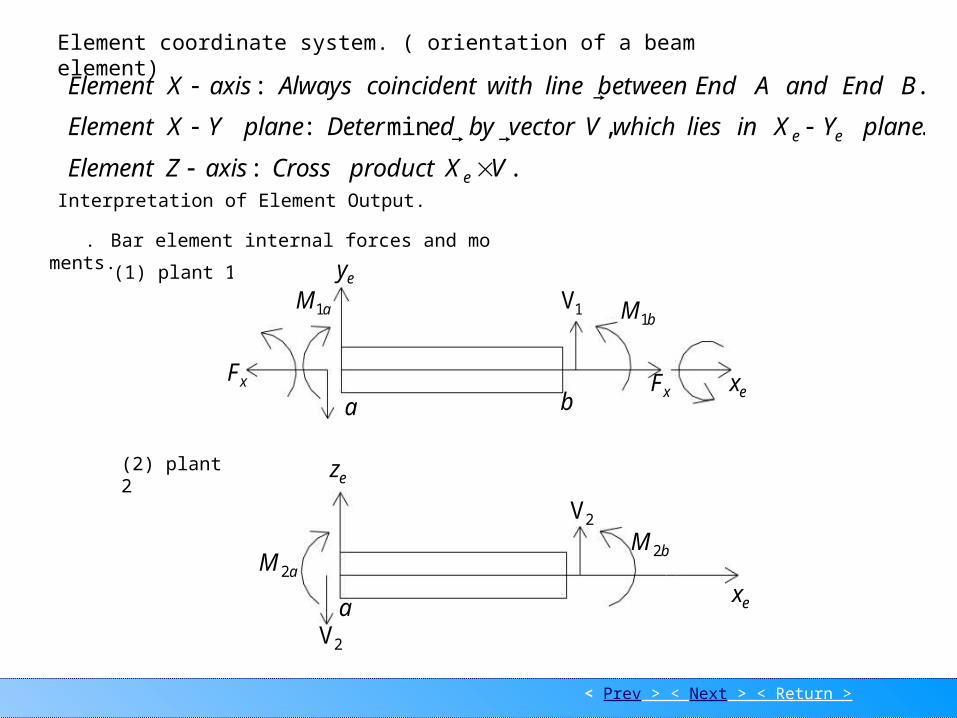
.:
.,min:
.:
VXproductCrossaxisZElement
planeYXinlieswhichVvectorbyedDeterplaneYXElement
BEndandAEndbetweenlinewithcoincidentAlwaysaxisXElement
e
ee
Element coordinate system. ( orientation of a beam element)
Interpretation of Element Output.
. Bar element internal forces and moments.
(1) plant 1
(2) plant 2
xF
aM1
ey
a b
1VbM1
xF ex
b
ez
aM 2
2Va
bM 2
2V
ex
< Prev > < Next > < Return >
Element coordinate sys.
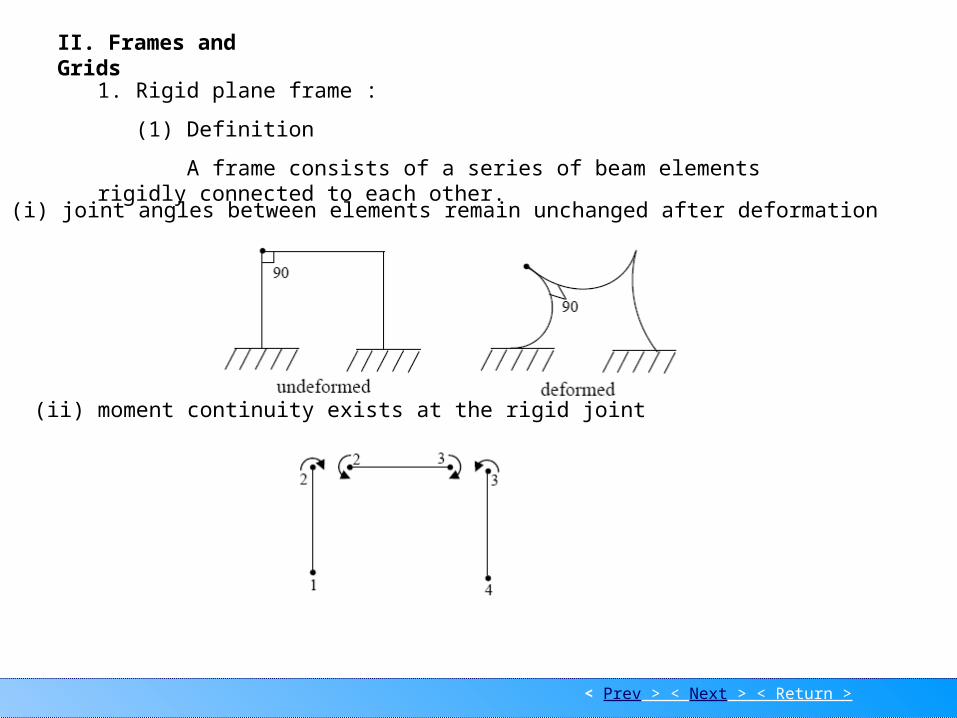
II. Frames and Grids
1. Rigid plane frame :
(1) Definition
A frame consists of a series of beam elements rigidly connected to each other.
(i) joint angles between elements remain unchanged after deformation
(ii) moment continuity exists at the rigid joint

< Prev > < Next > < Return >
Element coordinate sys.
(iii) element centroids and applied loads lie in the pane of the structure
(2) Two Dimensional Beam element
< Prev > < Next > < Return >
Element coordinate sys.
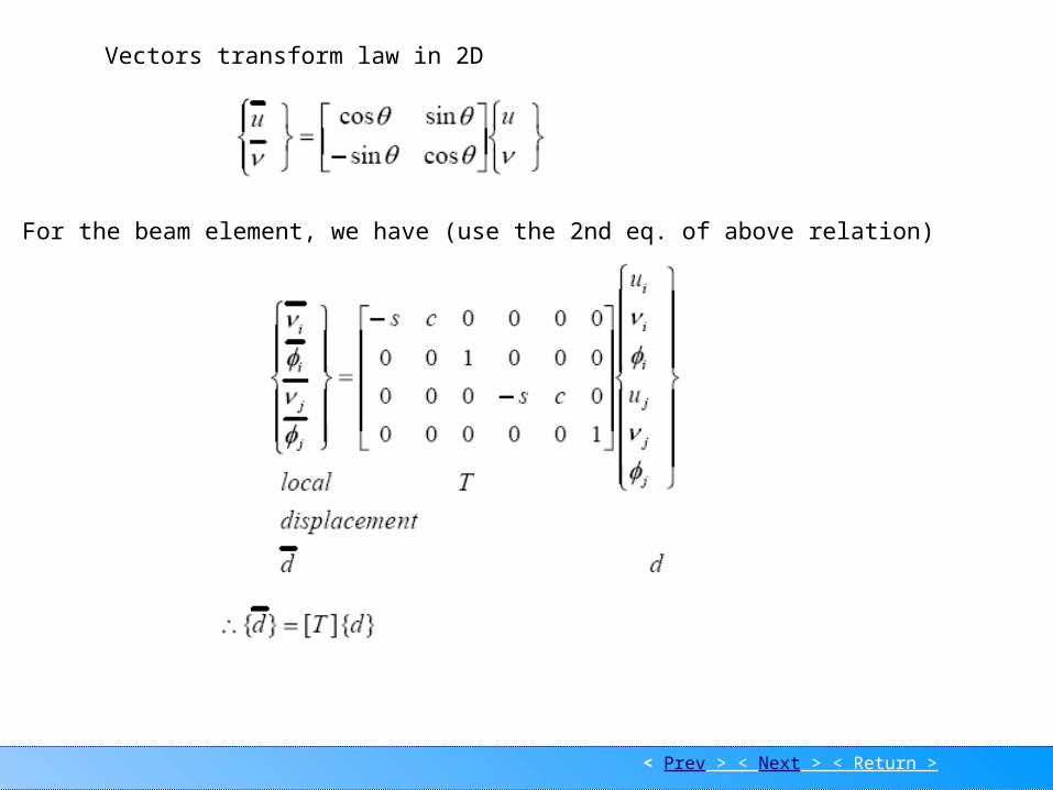
Vectors transform law in 2D
For the beam element, we have (use the 2nd eq. of above relation)
< Prev > < Next > < Return >
Element coordinate sys.
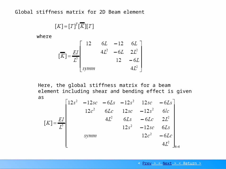
Global stiffness matrix for 2D Beam element
where
Here, the global stiffness matrix for a beam element including shear and bending effect is given as.

< Prev > < Next > < Return >
Element coordinate sys.
(3) 2D Beam element including axial force effect
Axial force effect
Combined with shear force and bending moment effects

< Prev > < Next > < Return >
Element coordinate sys.
or
or
and relate the local to the global displacement by
< Prev > < Next > < Return >
Element coordinate sys.
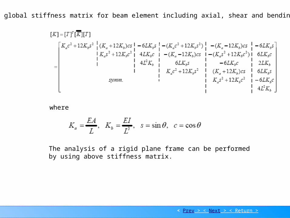
The global stiffness matrix for beam element including axial, shear and bending effects
where
The analysis of a rigid plane frame can be performed by using above stiffness matrix.
< Prev > < Next > < Return >
Grid-1
1F 2F
3F4F
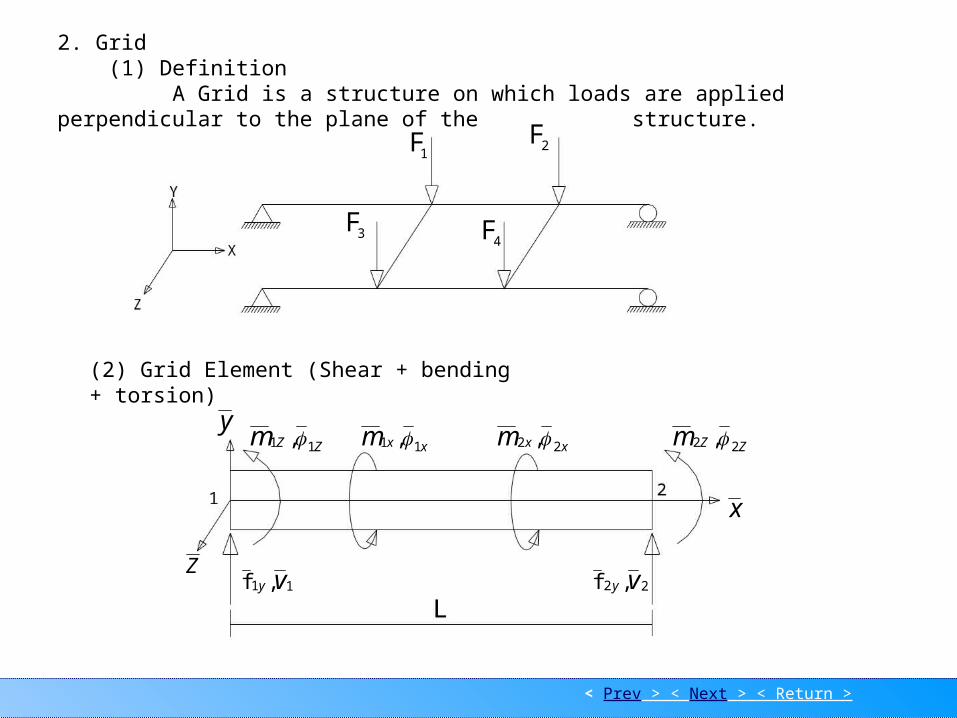
2. Grid (1) Definition A Grid is a structure on which loads are applied perpendicular to the plane of the structure.
(2) Grid Element (Shear + bending + torsion)
x
y
Z
ZZm 11 , xxm 11 , xxm 22 , ZZm 22 ,
11 ,f vy 22 ,f vy

< Prev > < Next > < Return >
Grid-2
xxm 11 , xxm 22 ,
x x
xxm , xxm ,
Torsional bar element stiffness matrix.
xx L
GJm
where G = shear modulus ; J =centroidal polar moment of inertia
xxxxx mmL
GJm 1212
x
x
x
x
L
GJm
m
2
1
2
1
11
11
Fig. Nodal and element torque sign conventions
The relationship between torque and twist is
< Prev > < Next > < Return >
Grid-3
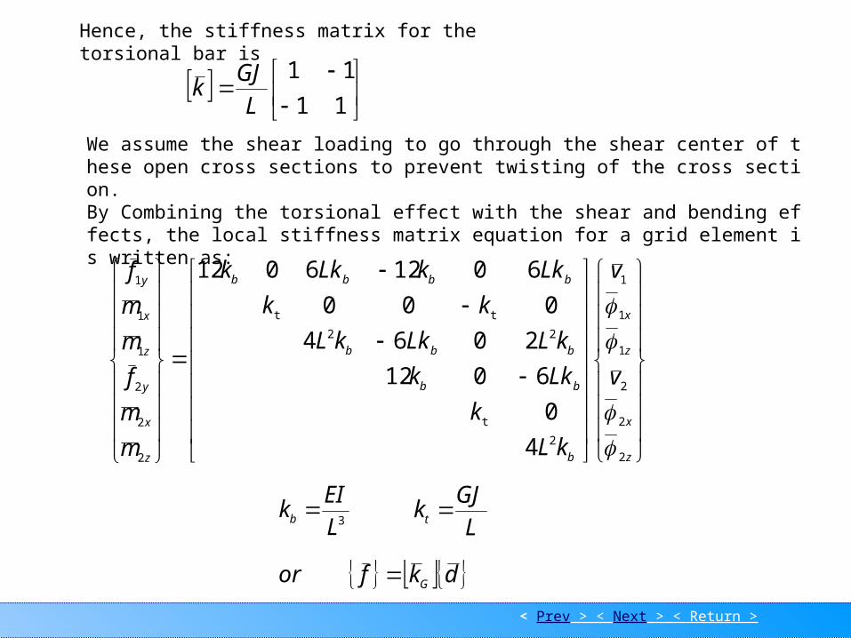
We assume the shear loading to go through the shear center of these open cross sections to prevent twisting of the cross section.By Combining the torsional effect with the shear and bending effects, the local stiffness matrix equation for a grid element is written as:
z
x
z
x
b
bb
bbb
bbbb
z
x
y
z
x
y
v
v
kL
k
Lkk
kLLkkL
kk
LkkLkk
m
m
f
m
m
f
2
2
2
1
1
1
2
t
22
tt
2
2
2
1
1
1
4
0
6012
2064
000
60126012
3L
EIkb L
GJkt
dkfor G
Hence, the stiffness matrix for the torsional bar is
11
11
L
GJk

Grid-4
< Prev > < Return >
The transformation matrix relating local to global D.O.F for a grid is
CS
SC
CS
SC
TG
0000
0000
001000
0000
0000
000001
L
xxC ij cos
L
zzS ij sin
Hence, the global stiffness matrix for a grid element is
GG
T
GG TkTk