definition of electrosubmersible pump (esp) design and …€¦ · · 2018-02-12esp design...
TRANSCRIPT

1
Definition of Electrosubmersible pump (ESP) design and selection workflow
Kennisagenda 2015/2016
Hans van ´t Spijker
Pierre Ungemach
29 June 2016
Dit project/onderzoek is tot stand gekomen in het kader van de Kennisagenda Aardwarmte van het ministerie van Economische Zaken, LTO Glaskracht Nederland en het programma Kas als Energiebron. Hierbij is de subsidie verstrekt door het ministerie van Economische zaken, LTO Glaskracht Nederland en het programma Kas als Energiebron.

2
CONTENTS
1. Samenvatting ................................................................................................................................... 3
2. Executive Summary ......................................................................................................................... 4
3. Introduction- scope of the survey ................................................................................................... 5
4. Background ...................................................................................................................................... 6
4.1. Pump types .................................................................................................................. 6
4.2. Electric submersible pumps......................................................................................... 8
5. Selecting and sizing an ESP pump ................................................................................................... 9
6. Survey of Electical submersible pumps and lineshaft pumps in Europe ....................................... 13
6.1. France-Paris Basin ..................................................................................................... 13
6.2. Germany. ................................................................................................................... 15
6.2.1. Molasse Basin (South of Münich). ....................................................................... 15
6.2.2. Upper Rhine Graben. ........................................................................................... 16
6.3. Other countries. ........................................................................................................ 16
6.4. Lessons learned ......................................................................................................... 16
7. Survey of ESPs in the Netherlands ................................................................................................ 17
7.1. Results ....................................................................................................................... 17
7.1.1. ESP configuration................................................................................................. 17
7.1.2. 5.2.3 ESP track record ......................................................................................... 19
8. Maintenance.................................................................................................................................. 20
9. Economics ...................................................................................................................................... 22
10. Recommendations and conclusions .......................................................................................... 24
11. Appendix 1: Setup of questionnaire .......................................................................................... 25
12. Appendix 2: Methodology to size and select ESP pump ........................................................... 26
13. Appendix 3: Technical Details On an ESP string ........................................................................ 29
13.1. Pump ...................................................................................................................... 29
13.2. Seal/Protector ....................................................................................................... 30
13.3. Motor ..................................................................................................................... 32
13.4. Power cable ........................................................................................................... 34
14. Appendix 4: Example of the maintenance schematics for ESP ................................................ 35
15. Appendix 5: Case study of sizing an ESP string .......................................................................... 36
15.1. WELL AND RESERVOIR DESIGN FEATURES ............................................................ 36
15.2. ESP DESIGN FEATURES........................................................................................... 37
16. References ................................................................................................................................. 38

3
1. SAMENVATTING
In deze studie worden het ontwerp en de selectiecriteria voor ESP pompen in Nederlandse geothermische putten geïnventariseerd. Een algemene aanpak voor het ESP-ontwerp wordt gepresenteerd. Voor de juiste selectie moet de Well Inflow Performance en de watersamenstelling bekend zijn, en gecombineerd met de verwachte debieten kan de ESP worden gedimensioneerd. Wanneer de ESP string goed is ontworpen, is een systeemrendement 55% haalbaar.
Er is een vragenlijst gestuurd naar de Nederlandse geothermische operators om informatie over ESP prestaties in te winnen. De ESP´s bij de diverse geothermische operators zijn geïnventariseerd. Er blijkt dat basisinformatie over Well inflow performance vaak incompleet is. Het merendeel van de ESP pompen is geleverd en geïnstalleerd door Baker Hughes. Van de onderzochte configuraties, werken een groot deel in het door de fabrikant geadviseerde bereik. In een aantal configuraties werkt de ESP aan de rand van het werkgebied, en in andere gevallen functioneert de ESP daarbuiten. Op basis van de nu beschikbare data is bepaald dat de gemiddelde ESP pomp momenteel een levensduur van ongeveer 5 jaar heeft in de Nederlandse geothermische putten. De verwachting is dat dit zal stijgen, als er meer gegevens over langere periode beschikbaar komt. Ook de prestaties van de ESP's in geothermische putten in Frankrijk en Duitsland zijn geïnventariseerd. De levensduur van een ESP pomp in franse geothermische putten is 4 jaar.
De gemiddelde CAPEX en OPEX kosten zijn onderzocht. De CAPEX kosten om een ESP te selecteren en installeren ligt tussen de 180 en 300 k€. Op basis van de beschikbare gegevens, komen de OPEX kosten voor de ESP tussen de 63 en 95 k€. Hierin zijn niet de elektrakosten voor de aansturing van de pomp in meegenomen.
Aanstormende operators wordt aangeraden om de beschreven ontwerpprocedure te volgen, zodat een energetisch systeemrendement van ongeveer 55% gehaald kan worden. Voor bestaande operators wordt geadviseerd om de CAPEX van een nieuwe installatie en de bestaande OPEX kosten (inclusief elektraverbruik) in kaart te brengen, en de terugverdientijd te berekenen. Om ervoor te zorgen dat de lage OPEX kosten worden gerealiseerd, is het raadzaam om de ESP prestaties in de tijd te volgen. Een voorbeeld van een monitoringprogramma is opgenomen. Daarnaast is een aantal aanbevelingen met betrekking tot het ESP-ontwerp opgenomen, zoals het gebruik van een tandem seal aan te bevelen. Tenslotte is de noodzaak benadrukt om de Well inflow curve en het systeemrendement periodiek te meten.

4
2. EXECUTIVE SUMMARY
In this study, the design and selection criteria for ESP pumps in Dutch geothermal wells are described. It consists of general approach workflow to design the ESP string. For that the well inflow performance, water composition need to be recorded and assessed, and combined with the allowable flow rates the relevant components can be selected. When properly designed, the overall efficiency of ESP string should be in the range of 55%.
A questionnaire has been send to Dutch geothermal operators to collect information on ESP performance and track record. The received information has been analysed and categorized. It is noticed that basic information on the well inflow performance data is incomplete or absent. Most of the ESP strings have been delivered and installed by Baker Hughes. Of the studied cases, most of the ESP operate well in the specified range. In some cases, the ESP runs at the edge of the working area, and in other cases the ESP working point is out of range. An average ESP lifetime of about 5 years is currently determined for the Dutch geothermal wells. It is well possible, that the ESP lifetime will increase. This can be better determined when more data is available over a longer time frame. Also, the status of the performance of ESPs in geothermal wells in France and Germany are reviewed. In France, the average lifetime of ESPs in geothermal wells is 4 years.
Average CAPEX and OPEX costs have been determined based on the available data. The CAPEX costs for selecting and installing an ESP are in the range between 180 and 300 k€. Yearly OPEX costs are estimated to be between 63 and 95 k€. Note that the costs for electricity for driving the ESP are not included here.
New operators are advised to follow the described design procedure, such that an energetic system efficiency of about 55% can be achieved. For the existing operators, it is advised to calculate the payback time by considering the CAPEX of installing an ESP and the OPEX costs for the existing installation (including electric power consumption).
An example of a monitoring program has been included.
Furthermore, several recommendations are made related to the ESP design, where the potential degradation of well and reservoir performance with time can be included. In order to reach the predicted lifetime, a tandem protector and chemical inhibition is recommended.
Finally, the need to record the well draw-down curve and the overall pump efficiency is emphasized.

5
3. INTRODUCTION- SCOPE OF THE SURVEY
The geothermal market in the Netherlands is strongly developing, and has resulted in about 13 operational geothermal plants in the Netherlands in 2016. All of these plants are mainly being utilized for the heating of greenhouses.
The ESP string, consisting of a motor, seals and pump, is an important part in the geothermal system. It lifts the water to the surface to allow for heat harvesting. The proper selection of an ESP is of utmost importance. Also maintenance deserves attention. However, currently information on the performance of the ESP pumps is limited. Therefore, this study is undertaken in the framework of the Kennisagenda 2015/2016, to collect and analyse the relevant data, and compare it with the performance in other countries.
The work described in this proposal mainly has a technical aim, and is focused on the ESP design and selection criteria:
Optimizing pump (life, COP) performance via a methodology integrating o domestic and foreign track records/failure analysis o local reservoir performance/well deliverability o borehole architecture/completion o fluid thermochemical profile
Securing product reliability, industry image and exploitation economics by using guidelines added to the candidate ESP manufacturer data request sheet.
Data has been collected by sending out a questionnaire amongst the operators. Also, Baker Hughes, who has delivered almost ESP pumps in the geothermal plant in the Netherlands, has been willing to share information on the pump performance.
This study starts with background (chapter 4) , theory (chapter 5), followed by a survey of the performance of ESP in Europe (Chapter 6). Then the ESP performance in the Netherlands is analysed (chapter 7), followed by maintenance (chapter 8), economics (chapter9), and recommendations and conclusions (chapter 10).

6
4. BACKGROUND
In this chapter the production modes for geothermal wells are reviewed. Also the three main pump types for the water production are considered. Of course, special attention will be paid to electric submersible pumps.
4.1. Pump types
There are five underground fluid production modes, self flowing, often surface boost pump sustained, and artificial lift, gas/air or submersible pump – either electric (ESP), lineshaft (LSP), turbine (TP) – sustained systems respectively. The main three are described in Figure 1. Here, volumetric pumps and gas/air lift concepts which fall out of the scope of the present survey will not be considered. As a result only centrifugal pumping systems will be investigated and their performances assessed accordingly.
Figure 1: Down hole artificial lift production pump principles
Enclosed lineshaft pumps ((E)LSPs) are mostly used in medium enthalpy wells, i.e. in wells at brine temperatures between 150 to 200 ⁰C , whereas electrical submersible pumps (ESPs) are mostly used in low enthalpy wells (i.e. at temperatures < 120 ⁰C).
The overall performance of the different pumping technologies is summarized in the Table below. For more details, we refer to chapter 6, where we review the utilisation of the various pumps in Europe.

7
Table 1: Overview of the figure of merits of the main artificial lift production pumps
PUMP TYPE PROS CONS REMARKS
(E)LSP(*)
No electric parts in hole Higher motor efficiency Lower speed/lower wear Withstands high temperatures (up to 200°C) Motor, seal, thrust bearing at surface. Probably (on purely mechanical grounds) longer life (less wear) Attractive costs
Immersion depth limited to 500-600 mbgl Longer handling (installation/removal) time Lower head/stage & flow/unit diameter Large pumping chamber ID requirements (13"
3/8)
Material definition of enclosing tubing & bearings (formation fluid dependant) Formulation of chemically & environmentally compatible enclosed shaft( make up) fluid lubricating Market (medium enthalpy sources) limited to few (2) operators
Impeller position needs adjustment at initial start up. Requires an almost perfect vertical (max 4° tolerance) pumping chamber.
ESP(*)
High immersion depth Long lifetime High flow/unit diameter Easier handling and shorter (installation/removal) time Ability to accommodate deviated well trajectories Ambitions (in a predictable time span high service temperatures (up to 250/300°C) Highly competitive ESP market (4 majors) Worldwide service facilities
Lower efficiency Electric parts in hole (insulation risk) Less accessible motor, seal, thrust bearing Higher operation speed(higher wear)
Impeller position set Some manufacturers provide direct cable to motor plug in (no splicing) and plant prefilling of motor lubricating oil
HTP(*)
No electric parts in hole, no mechanical seals Standard lubricating fluid Ability to accommodate deviated well trajectories and 9”
5/8 casings
and 1000 m setting depths & to afford multiple stop/restart sequences Long lifetime Withstands high temperatures (within the isolation packer temperature limits) Compact bottom hole assembly Low maintenance (OPEX) costs High flow rate potential
Low efficiency (additional energy conversion item) Packer anchoring shortcomings High costs Limited manufacturing/service facilities Sensitivity to aggressive (scaling) thermochemical environments
Inflatable, instead of mechanical, isolation packer recommended
(*) (E)LSP = (enclosed) lineshaft pump
(*) ESP = electric submersible pump
(*) HTP = hydraulic turbine pump

8
4.2. Electric submersible pumps
Mostly, Electrical Submersible Pumps (ESPs) are applied to lift the production brine. An ESP string consists of several components, as is illustrated in Figure 2. Starting from the bottom, it contains a sensor, motor, a set of seals to protect the motor, a pump. The motor is fed variable speed drive, transformer and an electric cable. The technical details for each component are described in appendix 3. It also contains a list with the material choice for these components.
Figure 2: Typical ESP string (Source: Schlumberger)

9
5. SELECTING AND SIZING AN ESP PUMP
The selection and sizing of an ESP assembly consists of several steps. It involves various aspects, including reservoir characteristics, well design and thermochemical properties of the formation water.
When a geothermal doublet is being drilled, exact information on the well performance is not yet available. Therefore, as a starting point, the well delivery curve is initially estimated, knowing the estimates on the reservoir characteristics (P50 transmissivity, etc.) and the well design. The required formulas to calculate that can be found in appendix 2. Based on that, a first order ESP design and selection can be made.
When the production well has been actually drilled, the well delivery curve should be measured. Also measurement of the water composition and the bubble point are recorded. When these data are known, the actual design of the ESP pump can be fine-tuned and completed. After that, the ESP pump can be ordered, which has typically a lead time of about 2-3 months.
This period matches roughly the time that is needed to drill the injection well. So, after drilling of the injection well, the ESP pump can be available, and can be installed into the production well.
More details on the selection of the ESP pump can be found in the flow chart of Figure 3 and in appendix 2. It is noted that the design requires expertise on several areas, and is mostly done by or in cooperation with a specialist from the manufacturer. An example of a case study is described in Appendix 4.

10
Figure3: Flow-chart of selection and sizing an ESP pump assembly.
Select transformer and variable speed driver
● Select transformer on required motor voltage
●Select speed driver for motor control
Select motor,seals and power cable
● Select seal
● Select motor
● Select power cable : selection is a compromise between cable size, voltage losses and costs. Cable siize maybe limited by available space between casing and tubing.
Select pump and pump set depth
● Select with casing diameter the pump series
● Select with required flow rate, the pump type
● Calculate the required number of stages based on pump type and TDH
● Set pump at lowest point (below lowest dynamic water level lowered by suction head) ,
● Check pump suction head with head determined by bubble point
● Select appriopiate materials for the pump
Calculate required power rating
● Calculate required power from flow rates, dynamic water level and required pressure at well head
● Calculate required total dynamic head (TDH)
Derive Well inflow curve
● Measure Well Inflow/delivery curve by performing a well test
● If not measured, estimate value from aquifer transmissivity, skin factor and friction losses in the casing

11
As can be seen in the flow chart, it consists of several steps. Very important in the appropriate selection, is the exact knowledge on the well delivery curve. An example of such a curve is presented in Figure 4.
Figure 4: Example of a well delivery curve
The actual well delivery curve is determined by the reservoir characteristics (transmissivity) and the well design (friction losses). The dynamic water level depends partly linearly and quadraticly on the flow rate, according to:
where h is the water level in (with respect to the ground level) [m]. If the well test data is not known, the inflow may be estimated from the (estimated) well transmissivity, skin factor and friction losses, as is described in appendix 2.
When the required pump power is known, the pump type can be selected. Also the motor, seals, power cable, transformer and speed drive can be selected. When doing that, it should be realized that in each step, additional efficiency losses should be accounted for. This means, for example, that the motor needs to deliver slightly (~10%) more power than the pump requires, and that the transformer is rated at higher power as well, to account for the resistance losses in the electrical cable.
These losses can be accounted for when considering the efficiencies in the complete ESP assembly (see also appendix 2). The overall efficiency can be ηtotal calculated by
Where
ηpump : pump efficiency, typically 70%
-300
-250
-200
-150
-100
-50
0
0 50 100 150 200 250 300 350 400
dyn
amic
wat
er
leve
l [m
]
Flow rate [m3/h]
Example of a drawdown curve

12
ηmotorl: motor efficiency, typically 90 %
ηcable: electrical cable efficiency, typically 97%
ηtransformer: efficiency of transformer, typically 99%
ηtfrequency: efficiency of frequency converter, typically 94%
This results in an overall efficiency of about 55% that should be achievable in most configurations.
In the design of the ESP pump, the following items should be considered as well:
1. Match the reservoir characteristics with the well design, to estimate what flow rates are
achievable, such that the friction losses remain low enough.
2. The ESP is mostly operated in a range of flow rates. This means that the pump is set at depth
at which the highest allowable flow rate is to be expected. Also, the efficiencies at the
boundaries (lowest and highest flow rate) need to be calculated. Also the performance of the
other parts, such as seals, motor etc., should be checked. In practice, when a pump is
correctly designed, an overall efficiency of about 55% should be realizable in most
configurations.
3. Check whether the pump set depth is below the hydraulic head corresponding to the
bubbling point, to ensure single phase flow.
4. When selecting the ESP, the frequency range should be taken into account. Normally, for
proper operation the ESP is allowed to vary between a lower threshold of 30 Hz and a
maximum threshold of 60 Hz. Do not exceed 70 Hz since this will drastically shorten the
lifetime of the pump.
5. The well inflow performance may change over time. This means that, if possible, the pump
should be selected such that a decline in productivity can be anticipated for.
6. Operate the pump in the specified pump ranges. To ensure a long life time and high
efficiency a proper thrust balance across the pump stages is required, to prevent early wear
in the stages. Operating the pump outside the specified range can cause serious down thrust
or up thrust effects.

13
6. SURVEY OF ELECTICAL SUBMERSIBLE PUMPS AND LINESHAFT PUMPS IN EUROPE
6.1. France-Paris Basin
Initiated in the late 1970s the development of the geothermal district heating (GDH) doublets heat extraction scheme, pioneered at the Melun l’Almont, South of Paris, emblematic site, peaked in the mid 1980s, with 54 completed doublets of which 36 remained online in the early 2000s. Since year 2008, GDH development resumed and 16 doublets and 7 triplets were achieved leading to 45 GDH systems serviced as of June 2016. This is illustrated in Figure 5.
Figure 5: Paris Basin GDH doublet locations
Needless to say this historical sequence provides a unique track record. In this respect it is worth adding that the geothermal source, a dependable carbonate reservoir of Mid-Jurassic (Dogger deposits) age at depths and temperatures ranging from 1 200 to 2 000 m and 54 to 83°C respectively, hosts an adverse fluid thermochemical environment (CO2/H2S aqueous system) leading to severe corrosion and scaling shortcomings if not properly inhibited down hole. Anti corrosion/scaling chemical inhibition increased the lifetime of the casings and ESP pump. Typical mitigating systems are displayed in Figure 6.
14
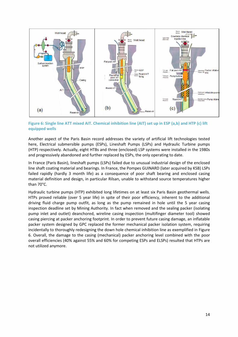
Figure 6: Single line ATT mixed AIT. Chemical inhibition line (AIT) set up in ESP (a,b) and HTP (c) lift equipped wells
Another aspect of the Paris Basin record addresses the variety of artificial lift technologies tested here, Electrical submersible pumps (ESPs), Lineshaft Pumps (LSPs) and Hydraulic Turbine pumps (HTP) respectively. Actually, eight HTBs and three (enclosed) LSP systems were installed in the 1980s and progressively abandoned and further replaced by ESPs, the only operating to date.
In France (Paris Basin), lineshaft pumps (LSPs) failed due to unusual industrial design of the enclosed line shaft coating material and bearings. In France, the Pompes GUINARD (later acquired by KSB) LSPs failed rapidly (hardly 3 month life) as a consequence of poor shaft bearing and enclosed casing material definition and design, in particular Rilsan, unable to withstand source temperatures higher than 70°C.
Hydraulic turbine pumps (HTP) exhibited long lifetimes on at least six Paris Basin geothermal wells. HTPs proved reliable (over 5 year life) in spite of their poor efficiency, inherent to the additional driving fluid charge pump outfit, as long as the pump remained in hole until the 5 year casing inspection deadline set by Mining Authority. In fact when removed and the sealing packer (isolating pump inlet and outlet) deanchored, wireline casing inspection (multifinger diameter tool) showed casing piercing at packer anchoring footprint. In order to prevent future casing damage, an inflatable packer system designed by GPC replaced the former mechanical packer isolation system, requiring incidentally to thoroughly redesigning the down hole chemical inhibition line as exemplified in Figure 6. Overall, the damage to the casing (mechanical) packer anchoring level combined with the poor overall efficiencies (40% against 55% and 60% for competing ESPs and ELSPs) resulted that HTPs are not utilized anymore.

15
Starting in the 1980s, In the meantime, BYRONJACKSON, a water pump manufacturer became a major ESP supplier by assembling a cooling heat exchange device around the motor OD. This turned into disadvantage when corrosion of pumping chambers led to 10"3/4 lining therefore abandoning this initially promising alternative. Other manufacturers proved to be more successful. The poor ESP lifetime record could be progressively upgraded thanks to improved material (higher steel, grades, K Monel coating) definition and plant running, loop regulation, adequate variable speed drive, and, last but not least, generalised implementation down hole chemical inhibition practice, resulting as of late 2015 to an average EPS life time record nearing 4 years with a 5 years target ambitioned in the near future.
6.2. Germany.
6.2.1. Molasse Basin (South of Münich).
Thanks to the attractive Feed in Tariff (FIT) policy promoted by the Federal Government investors got involved in projects aiming at combining heat and power (CHP) production via doublet schemes exploiting a hot (120°-160°C) water resource from a deep seated (3 500-4 500 m) karstified carbonate reservoir. These sites are illustrated in Figure 7.
Figure 7: Molasse Basin GDH and CHP doublet locations
However, the target flow rates, 500-600 m3/h, requiring 800 to 900 m deep, rated up to 2 000 HP, ESPs set by the operators were deemed (and proved) exaggeratedly ambitious. The combination of the high flow rates of about 300-700 m3/h, high temperatures between 120 and 145 ⁰C and the highly calciferous water chemistry, made that the initially installed ESP pumps had a lifetime of less than a week. One ESP manufacturer, Baker Hughes, has reconsidered the design for the severe conditions, and made improvements on bearings, and material selection. As a result, the average lifetime of the pumps could be extended to about 6 months. For the time being, there are limited expectations that they last more much longer, unless the regulation forbidding deep aquifer

16
injection of chemical corrosion/scaling inhibitors be lifted [1,4,5]. Actually, despite modification of impellers profile, little improvements in defeating scaling damage and subsequent shaft bearing breakages could be noticed.
6.2.2. Upper Rhine Graben.
At the Landau and Insheim CHP production sites (Palatine province) enclosed line shaft pumps proved effective after initial problems in design and handling of the shaft lubricating liquid were sorted out. Here teflon shaft bearings proved to be inadequate and were replaced by bronze bearings which required a custom designed, make up, shaft lubricating fluid. In the Upper Rhine Graben, the ITT Gould ELSP pump manufacturer, assisted by Jack Frost Eng. Group, holds the leadership with three units sold and operated at Landau (now shut in due to casing leakage), Insheim and, recently, Rittershoffen (Nothern Alsace), at source temperatures standing within the 150-165°C range
ESP manufacturers (i.e. Baker Hughes/Centrilift and Schlumberger Reda) have declined here. Fonroche Geothermie (FG), operator of the Vendenheim and Eckbolsheim (NE of Strasbourg) sites, with bottom hole temperatures close to 200°C, has therefore planned acquiring ELSPs from ITT Goulds/J.Frost for producing their wells (drilling spud in date, January 2017 at Vendenheim). The average ELSP life in the Upper Rhine Graben, at a temperature of, 165°C is estimated at three years.
6.3. Other countries.
In Iceland, the Reykjavick district heating, ELSPs are used at 135°C thanks to abrasion resistant, city water lubricated, teflon shaft bearings. They show overall a 4 year life expectation.
In Turkey, ELSPs have failed in a matter of weeks (days even) as a result of devastating enclosing tubing corrosion and related bearing/shaft dismantling, in a thermochemically sensitive corrosive and scaling environment. ESPs, until recently, were absent on the medium enthalpy (150 to 200°C source temperatures) scene.
ELSPs have in many instances overcome the severe thermochemically induced flaws long experienced on the Southern California Imperial Valley hot wells (150 to 180°C, East Mesa, Brawley, Heber and Salton Sea fields, cumulating ca 200 pump sustained production wells). Here, two to four year year pump lives are currently achieved and the three year target ambitioned by operators can be viewed realistic, provided and thorough downhole chemical corrosion/scaling inhibition practice be implemented.
6.4. Lessons learned
Based on the above mentioned experience of the various pump types in Europe, the status can be summarized as follows:
1. The use of in hole corrosion and scaling inhibition increases the pump life expectation.
2. The performance of lineshaft pumps is strongly site specific, and in most instances limited to medium enthalpy producer wells, within the 150°C to 200°C range, where three year life can be realistically targeted.
3. ESPs are definitely leading the low enthalpy geothermal sector (70- 120°C ) range with 4 to 5 year pump life objective. ESPs could step into the medium enthalpy slot manufacturing majors provided so wish.

17
7. SURVEY OF ESPS IN THE NETHERLANDS
7.1. Results
A questionnaire has been composed to collect the data on ESP performance and track record in the Dutch geothermal plants. The questionnaire form is listed in Appendix 1. This questionnaire has been sent the operators to collect the information. Out of the 14 operators, 8 responded and filled in the questionnaire. Also, information on well schematics and ESP configuration has been collected. This information is used in this study.
Also Baker Hughes, which is the supplier of most ESP pumps in the Netherlands has delivered, has been contacted. Baker Hughes has provided the pump curves.
It is noted that the ESP pumps are operated in various configurations in the geothermal loop. The following configurations are employed:
- Geothermal loop with degasser: Most geothermal loops operate in combination with a
degasser. In this configuration, the water is degassed and the gas is fed via the annular
towards the phase separator (degasser), from where it is transported to the gas cleaner and
the cogeneration unit (in Dutch: WKK). In this configuration, the additional gas back pressure
on the annular should be accounted for in the well delivery curve.
- Geothermal loop without degasser: In this geothermal loop configuration, the geothermal
brine is kept under pressure, such that (partial) degassing is prohibited. There are two cases :
o Low gas content: In this case where the gas content is low, the gas is kept under
pressure, and degassing is prevented.
o Moderate gas content: In this case, the water is partly degassed, and the gas is fed
back into the (cooled) water behind the heat exchanger. Here the gas pressure in the
annular needs to be accounted for.
- Geothermal loop without injection pump: In one geothermal doublet, the injection well
shows good injectivity and therefore, the ESP pump can be used to both extract the
formation brine from the production well and inject the brine into the injection well.
For most of the analysed geothermal doublets, well delivery inflow curve has not been recorded after the drilling of the production well. In the other cases, the well delivery inflow performance can only be estimated from the data of the intake pressure.
7.1.1. ESP configuration
In the Dutch geothermal wells, mostly ESP pumps of Baker Hughes have been installed. In one geothermal doublet, a pump of Canadian Advanced ESP has been installed. In another site, a pump of Schlumberger has been installed in the past. However, the doublet is not operational. So far, no ESP pumps of General Electric have been installed in the Dutch geothermal wells.
Table 2 summarizes the ESP set depth and the flow rates.

18
Table 2: ESP set depth and flow rates in the studied geothermal wells.
As can be seen in the Table, the ESP pumps operate between 100 and 300 m3/h, and the pump is set at a depth below 300 m.
The pump curves, are received from the manufacturer, have been analysed as well. An example of such a curve is shown below. As can be seen in the Figure, the pump operates at a too low flow rate for the selected pump, and lies at the edge of the specified range of the manufacturer.
For the 8 studied cases, 4 of the ESP operate well in the specified range. In 2 cases, the ESP runs at the edge of the working area, and in 2 other cases the ESP working point is out of range. It is noted that in the geothermal wells the productivity will change over time, and thus that the selected and installed pump can loose efficiency.
Figure 8: Example of a pump operating at the edge of advised working area.
It was not possible to estimate the overall ESP system efficiencies from the received data. We note that an efficiency of about 55% should be achievable in most configurations (see chapter 3). In this respect, we notice that from an earlier study in 2013 [6] that some ESP pumps operated at an efficiency of only 35%.
Therefore, we recommend the operators to check the efficiencies of the ESP configuration. This may save costs for the operators. For example, consider an ESP pump operating at 400 kW. When the efficiency is 35% instead of 55%, this will result in an avoidable OPEX costs of € 40.800,- on a yearly basis (assumed electricity price of € 0,06/kWh and an operation time of 8500 hours).
Enterprise Depth ESP [m] static water level [m]
Flow rate summer
[m3/h]
Pressure well head
summer [bar]
Flow rate summer
[m3/h]
Pressure well head
summer [bar]
1 200 7 200 7
2 110 10 110 10
3 538 35 100 4 160 4
4 322 80 190 315
5 670 38 ? 180 300
6 450 130 4 to 5 180 4 to 5
7 671 50 250 250
8 597,5 250 250
9 366,75 110 170
10 617

19
7.1.2. 5.2.3 ESP track record
The track record data, as collected by the ESP questionnaire, are summarised below.
Table 3: ESP replacements in the Dutch geothermal wells
As can be seen in the Table, 6 ESP pumps have been replaced in the past period. In most cases, not because the pump failed, but merely was replaced either by leakages in the production tubing, or to adapt the pump to be more suitable for the well inflow curve.
So far, the data is too limited to estimate the average lifetime of the ESP pumps in the Netherlands. One Centrilift pump has showed a lifetime for 6 years. For comparison, Baker Hughes has the experience that the average lifetime of Centrilift pumps in the North Sea in offshore oil fields amounts to 8 years [3]. Given the current experience, Baker Hughes estimates that a lifetime of about 5 years in Dutch geothermal applications can be accounted for [3]. Probably, the lifetime may exceed this in the near future.
This lifetime is markedly higher than the lifetime of ESP in the geothermal plants in the Paris basin. Here a lifetime of about 4 years is the common practice [4]. This is probably related to the fact, that the French aquifer contains the corrosive gas H2S, which makes the wells sour and give harsh conditions for corrosion control.
Table 4: Summary of the interruptions of the ESP functioning
Table 5 summarised the results for the ESP interruptions. In all these situations, the interruptions are not related to the ESP functioning but due to external factors. The most common reasons are : 1) electric power failure in the surface installation, 2) maintenance on the surface installation, and 3) planned operations for e.g. well logging. It is advised that the total number of starts and stops is to be minimized. The ESP pumps are designed for continuous operation, and the shaft and bearings load are designed for that. During the high torque and shaft loads may reduce the lifetime of the ESP pump.
Enterprise
Pump/Motor
replaced? # occasions Cause
1 yes 1 after 2 years, motor corrosion and electrical shortcut
2 yes 1 after 6 years, seal broken, also corrosion seen
3 No/yes 2
leak in production tubing, defect at splice, also pump selected for higher flow rates
higher flow rates (> 100 m3/h),
4 yes 1 Lower e-costs, also casing measured
5 no 0
6 yes 1 ESP, pump broken off
7 no 0
8 no 0
9 yes 1 Impeller sections reduced from 24 to 10, leak in producction tubing
10 no 1
Enterprise
Number of stars-stops
first year
Number of stars-stops in
normal operations
Time duration
between start -stops Cause
1 3x 3x ~ 30 minutes power failure
2 3x 3x ~ 30 minutes power failure
3 20 x 20 x 1 hour-3 weeks
4 5x 5x ~ 0,5-1 weeks planned
5
6 20x/year 20x/year ~ 15 minutes short maintenance
7 total 92x, now 5x per year total 92x, now 5x per year ~ 15 minutes
8 total 96x, now 5x per year total 96x, now 5x per year ~ 15 minutes
9
10 10x per year 10x per year
11 no data yet

20
8. MAINTENANCE
There are various parameters that have impact on the lifetime of an ESP. They are summarized below.
Table 4: Impacts impairing ESP life
1 Geothermal environment
Hostile (corrosion/scaling) thermochemistry
Solution gas content. High GLRs
Suspended particle entrainment
Abrasive solids
High formation temperatures
Degradation of reservoir performance
2 Human environment
Non or poorly trained personnel
Odd ESP handling (POOH, RIH) practice
3 Design and operation
Inadequate design features (ESP sizing, material definition, off range functioning point, ...)
Excess ESP stop/restart cycles
Insufficient/wrong operation data, e.g. o Inaccurate fluid data can cause the BHP of the pump to be more than predicted
which could cause motor overload
Transformer, frequency converter, current harmonics filter compatibilities
Reactive current, power quality
Lack of, or loose maintenance/surveillance protocols, o May cause damage due to blocked filters or failure of injection pump
Lack of corrosion/scaling inhibition and abatement
Off range operating point (thrust wear)
To optimize the life time of an ESP pump, it is recommended to monitor the critical parameters periodically. This can be done by the manufacturer, who can measure the e.g. voltage, current, powers etc and report that to the operator. It is also possible to measure the performance independently by recording periodically all critical aspects, and identify possible problems. An example of such a monitoring program is described in Appendix 4. Also it is advised to monitor the water samples frequently, in order to notify any changes in water composition.
Additionally, it is recommended to utilize proper scale and corrosion inhibitors, in order to protect the pump. Note that, by doing so, that only the interior pump parts will be protected. The exterior parts are not protected in this way. To prevent corrosion for the parts below the dynamic water level, it is recommended to perform a regular treatment via the annulus.
In the case that an ESP fails, the pump needs to be pulled out of hole. It is advised to prepare a work plan that can be executed directly in the case when a failure occurs. This implies that a backup ESP system should be available. When this is properly arranged, it may be possible to set a new ESP system in operation in 2-3 days timeframe.

21
It is advised that the back-up ESP system, is arranged by each operator. This can be stored on site, or at well-conditioned storage facility at the manufacturer. Optionally, it can be considered that a reconditioned motor is kept as a back-up, however at the expense of a shorter lifetime. Additionally, a group of operators might select jointly a back-up motor, in the case that such a motor is applied in several wells (see Table 1).

22
9. ECONOMICS
The capital investment (CAPEX) and yearly operation/maintenance (OPEX) running costs may be appraised from the most recent ESP purchases and OM contracts practiced in the Paris Basin of France which lead to the following cost estimates for ESPs, rated between 250 kWel (335 HP) and 500 kWel (670 HP). They are summarised in the Tables below.
Table 5: ESP CAPEX
ITEM
DESCRIPTION COST (k€)
Min Max
1 Pump
2 Upper Seal
3 Lower Seal
4 Motor
5 Cable
6 Monitoring/Control Unit
7 Shipment
8 Field service (ESP operator)
9 ESP RIH crew
TOTAL 180 300
Table 6: ESP OPEX
ITEM
DESCRIPTION COST (k€/yr)
Min Max
1 Monitoring/Light maintenance 10 10
2 ESP replacement (*) 35 60
3 POOH damaged ESP (*) 5 7
4 RIH new ESP (*) 7.5 9
5 Contingencies 6 9
TOTAL 63.5 95
(*) yearly provision assuming a four year life

23
The CAPEX and OPEX costs for the standard ESPs in the Dutch geothermal wells have similar price levels as those the France and these numbers can be used to calculate in financial cost schemes.
Off course, the CAPEX and OPEX costs may differ for each geothermal site to another, since these costs depend on various factors. CAPEX costs primarily depend on the flow rate, pump set depth, reservoir characteristics and the water quality. OPEX costs depends on the lifetime, monitoring and yearly provision costs for installing a new ESP. Costs for electrical power consumption should not be omitted as well, which in turn depends on the overall system efficiency and the operation time. Here we note, that some ESP pumps operate at a lower efficiency than the overall 55% efficiency that is normally achievable. Therefore, we recommend the existing operators to check the efficiencies of the ESP configuration and calculate the avoidable electrical costs, and estimate whether it is feasible to redesign and install a new ESP pump.

24
10. RECOMMENDATIONS AND CONCLUSIONS
Based on the track record of thirty year exploitation of geothermal doublets in the Paris suburban area, and of a seven year geothermal heating record in the Netherlands and on the factors impacting ESP life, the following conclusions and recommendations may be drawn, in order to secure a five to six year ESP target life:
Utilize preliminary design guidelines from a prefeasibility survey based on expected reservoir performance assessed from (i) available data bases (NLOG [7], Thermogis [8]) and P50 permeability likelihood, (ii) fluid properties, and (iii) well architectures.
After the well testing, produce detailed ESP specifications fitted to production well deliverability curve and expected nominal functioning point flow rate. This feasibility assessment will validate further ESP design and associated components such as transformer and frequency converter.
ESP design should account for potential degradation of well and reservoir performance with time thus allowing for adjusting to modified nominal functioning characteristics (voltage, amperage, frequency) within the induction motor/thrust operating range.
ESP bottom hole assembly should imperatively include tandem (two seal) protector modules.
Down hole chemical inhibition injection lines should be implemented to ensure well casing and ESP integrities.
Sound O&M protocols, down-hole parameter monitoring of pressure temperatures, in hole control of ESP critical parameters, supplying precursory indicators of potential system failures, should be the rule. This includes the monitoring of overall efficiencies and the reactive power to identify the actual performance.
Heat plant operation and ESP management require trained personnel and either in-house or outsourced OM monitoring/service skills and facilities with respect to ESP POOH and RIH handling.
Spare ESPs and on duty fast service should be programmed to limit geothermal stand by periods consecutive to equipment failures.
Such policies obviously have a cost, estimated, with respect to yearly OM, between 64 and 95 k€, depending on ESP rated capacities. They should secure a five year ESP life which, with growing time and experience could increase over time.
Furthermore, it is advised to collect reliable data, especially on the well inflow delivery curve. Also, regular independent measurement on the ESP system gives insight in the overall system performance and efficiency. We also recommend installing a nitrogen control line, by which the dynamic and static water levels can be recorded. In this way, the well draw down curve can be recorded independently from the manufacturer.

25
11. APPENDIX 1: SETUP OF QUESTIONNAIRE
Questionnaire ESP pump In this questionnaire, the information on the ESP performance is collected. In case we refer to ESP pump, we mean to the complete ESP assembly that is thus the assembly at the bottom of the production tubing and includes the ESP pump, ESP motor, power cable, seals and gauge. We would like to receive information on the following issues:
1. ESP pump design - Could you provide us the well design report of the production well?
- Could you provide the well test data report of the production well?
- Could you provide us the brine properties (bubble point, temperature, pH, salinity etc)
- ESP type, manufacturer
- Frequency converter type and characteristics
- ESP transformer type and characteristics
- ESP submersion depth
- ESP outlet pressure and manometric head
2. ESP operation statistics - What is the COP of the geothermal installation?
- What are the flow rates and operational pressures (in summer and winter)?
- How much hours per year is the ESP pump in operation?
- Average monthly and yearly discharge rates
- Number of stop/restart events; operational duration between start and stop and standby
duration between stop and restart in case of ESP failure/replacement
3. Track record of installed/operating ESPs What is the history of ESP pump replacements and workovers?
- Has the ESP pump been replaced intermediately (and why?) - Did failures and interruptions in the ESP functioning occur? If yes, what are the causes and frequency? - Were workovers related to ESP pump necessary? If yes, what are the causes and frequency?
4. Miscellaneous issues - Are there other items that deserve attention, that have not listed been in this questionnaire?

26
12. APPENDIX 2: METHODOLOGY TO SIZE AND SELECT ESP PUMP
Below the calculation methodology is described to calculate the required powers, and the selection of the pump, and other components.
Step 1: Well inflow curve
If well test data is not available data, the draw down curve may be estimated using the Darcy´s law, and the friction losses in the tubing and the casing:
Combined this gives the production pump head:
Where ΔPop is the pressure difference in operational pressure at the well head.
Step 2: Calculate required pump power
The required power is calculated as the product of the flow rate and the required pressure difference, divided by the overall pump efficiency. Expressed in the conventionally used units of flow rate, Q in (m3/h) and, pressure P in bar, this yields .
Here η expresses the overall efficiency.
As a starting point, an overall efficiency of η of 0.65 is taken.
Step 3: Calculate pump set depth
The pump should be set below the bubbling point.
Step 4: Selection of motor and seal
Motor and seal are to be selected based on the selected pump. The motor power should be oversized by about 5-10% to accommodate for losses.
Step 5: Selection of electric cable
Selection is based on cost, allowable voltage drop and well temperature. Based on the manufacturer data, a proper selection can be made. For a typical example [2], see the Figure below

27
Figure A1.1: Typical ratings for an ESP power cable for a Centrilift pump [2]
Step 6: Selection of transformer and frequency converter
When the power losses are calculated, the appropriate transformer rating can be determined. Use an over sizing of 5-10%. Select a transformer with various output voltages, in order to accommodate for varying motor settings and adaptation to future motor modifications.
Step 7: Calculate overall efficiency
The overall efficiency ηtotal is calculated by
Where
ηpump : pump efficiency
ηmotorl: motor efficiency
ηcable: electrical cable efficiency

28
ηtransformer: efficiency of transformer
ηtfrequency: efficiency of frequency converter
NOMENCLATURE
Variables
E (MWh) = energy L (m) = mid reservoir well spacing NC = number of casing phases NHH = number of heating hours/year P (bar) = pressure ∆P (bar) = pressure variation Q (m
3/hr) = flowrate
S = skinfactor W (MW) = power a (Q) = heat exchanger pressure loss coefficient kh (darcy meter) = intrinsic transmissivity (m) = radius (m) = top reservoir vertical depth
= pump efficiency (cp) = dynamic viscosity Ø = porosity (kg/m
3) = density
(°C) = temperature a = distance from the center of a rectangular
block to the side
Subscripts
c = casing cf = casing friction el = electrical esp = electro submersible pump geo = geothermal reservoir hxi = heat exchanger inlet hxo = heat exchanger outlet i, inj = injection p, pro = production Se = skin effect Sip = surface injection pump T = tubing tf = tubing friction th = thermal ts = thermosiphon w = well 0 = static state

29
13. APPENDIX 3: TECHNICAL DETAILS ON AN ESP STRING
13.1. Pump
Type: single shaft multistage centrifugal.
Description: each stage includes an impeller and diffuser set. The impeller rotates with the shaft
while the diffuser, linked to the pump body, remains static. The diffuser directs the fluid from the
impeller outlet to the next, upward, stage inlet.
The type and number of stages depends on the required flow (Q) and total manometric head (TMH).
The downward pump intake is integrated to the pump body. To avoid solution gas escape, bubbling and ultimately pump cavitation, a sufficient height of water (compensating bubble point pressure and NPSH) is needed. In case of higher gas water ratios (GWR) and bubble point pressures a degasser module below the pump intake is recommended.
A. Pump Floater and Compression operating modes
B. Implications of Floater and Compression operating modes on down and up axial thrust
Figure A3.1: ESP pump operating modes with respect to axial thrust handling strategies (source: Schlumberger)

30
There are two designs regarding operating modes depending on whether the target operating point (OP) remains within (floater mode) the pump range or outside (compression mode).
In floater mode impellers stand axially free from pump shaft (in range OP). In compression mode impellers are axially fixed to the pump shaft which allows operating off range as sketched in Figure A3.1.
C. The latter mode is favoured by geothermal operators in order to cope with low (summer, seasonal heat demand) flow rates and/or anticipate further degradation of well
However it may happen (from cases recorded in the Paris Basin) that well and reservoir higher than expected performance, in which case the pump is subject to up thrust (
). Material definition will depend on local operating conditions and geothermal fluid chemistry. In the Paris Basin the coating and bulk materials and alloys are listed in Figure A3.2
Figure A3.2: ESP pump description and material assignment (source: Schlumberger)
13.2. Seal/Protector
This unit, coupled to the pump and to the motor, which includes one or several oil filled chambers, is assigned five main functions namely:
Motor to pump (torque) coupling,
Compensation of thermally induced expansion and losses,
Recovery of the axial thrust caused by pump weight, fluid transfer and centrifugal forces,
Secure a pump to motor seal by preventing migration of the reservoir fluid to the motor, and, last but not least,
Pressure equalising between the motor and the well annulus.
It includes a series of bags and a labyrinth pathway both illustrated in Figure A3.3 and Figure A3.4.
Bags are seal chambers made of oil filled elastomeric membranes. They act as an equalising device via oil thermal expansion evacuating the excess oil to the formation. It works the opposite when thermal contraction drains back the formation fluid to the

31
elastomeric membrane face. The elastomeric composition depends on formation fluid chemistry and temperature.
The Labyrinth is a seal chamber which achieves oil to fluid separation via gravity segregation. Oil expansion/contraction during pumping operations causes evacuation/drainage toward the interior/exterior of the chamber, concluded by natural gravity separation.
Figure A3.3: Seal/protectors, chambers/labyrinth description and operating cycles
Figure A3.4: ESP seal/protector description and material assignments (Schlumberger)
An example of a Labyrinth pathway, serially connected to two, parallel mounted, bags is described in Figure A3.3. Note in this example that the transfer of the pump axial thrust is achieved by an

32
additional chamber at the bottom of the protector. It includes two thrust bearings separated by a thrust runner which recovers both compressive (down thrust) and shear (up thrust) stresses conveyed by the pump shaft. The number of seal chambers depends on the maximum potential expansion/contraction volumes within the well, themselves dependant on motor power and formation fluid temperature. Whenever one chamber gets contaminated by the formation fluid, access to the next chamber, isolated by a seal part, is accommodated via a set of valves.
It is strongly recommended to order a tandem seal/protector set while designing an ESP assigned to geothermal service.
Although site and fluid specific, most seal/protector materials often consist of noble steel alloys. This is displayed in Figure A3.4.
13.3. Motor
Type: induction bipolar three phase squired cage. (Figure A3.5 and Figure A3.6)
Description: ESP motors are filled with a purified, dielectric mineral oil for bearing lubrification and thermal conductivity purposes. Rotors weight is transferred to the motor thrust bearings. The motor dissipated heat is transferred to the formation fluid flowing along the motor body. The motor top is equipped with a Pot Head allowing for plugging in the 3 phase electric cable.
The standard temperature limit stands at 175°C. Selected metal alloys very similar to those of Seal/Protectors are listed in Figure A3.4.
Figure A3.5: ESP motor description and material assignments (Schlumberger)

33
Figure A3.6: ESP motor and protectors/seals (Baker Hughes)

34
13.4. Power cable
The cable is clamped to the production tubing/riser before getting plugged into the motor pot head to supply power to the motor windings along preventing fluid intrusion. Owing to diameter restrictions flat cable of the type shown in Figure A3.7 is used in geothermal service. In the past the flat cable was limited to the wider diameter pump section and connected via a splice to the lower coaxial round cable. Some ESP manufacturers still practice the splice connection instead of plugging the cable straight forwardly into the motor.
Figure A3.7: ESP power cables (Source: Baker Hughes)
35
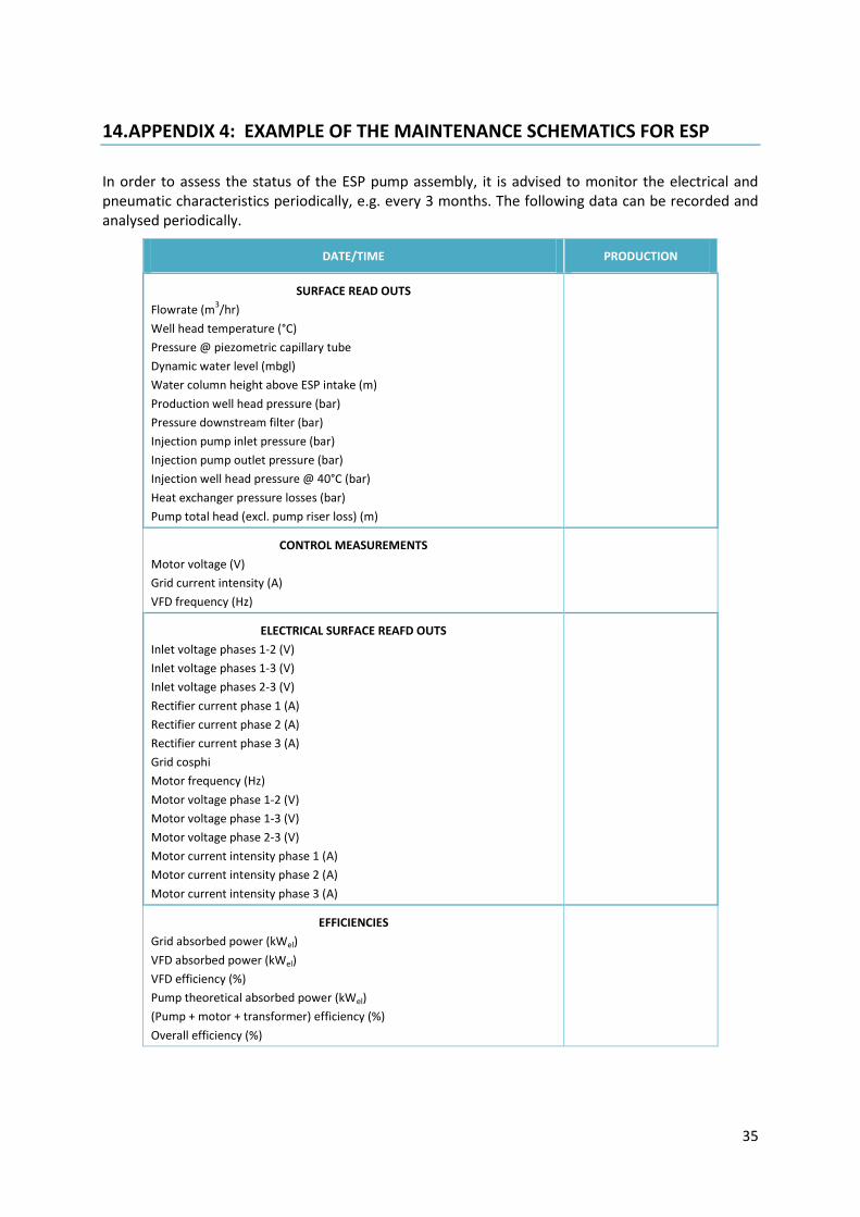
14. APPENDIX 4: EXAMPLE OF THE MAINTENANCE SCHEMATICS FOR ESP
In order to assess the status of the ESP pump assembly, it is advised to monitor the electrical and pneumatic characteristics periodically, e.g. every 3 months. The following data can be recorded and analysed periodically.
DATE/TIME PRODUCTION
SURFACE READ OUTS
Flowrate (m3/hr)
Well head temperature (°C)
Pressure @ piezometric capillary tube
Dynamic water level (mbgl)
Water column height above ESP intake (m)
Production well head pressure (bar)
Pressure downstream filter (bar)
Injection pump inlet pressure (bar)
Injection pump outlet pressure (bar)
Injection well head pressure @ 40°C (bar)
Heat exchanger pressure losses (bar)
Pump total head (excl. pump riser loss) (m)
CONTROL MEASUREMENTS
Motor voltage (V)
Grid current intensity (A)
VFD frequency (Hz)
ELECTRICAL SURFACE REAFD OUTS
Inlet voltage phases 1-2 (V)
Inlet voltage phases 1-3 (V)
Inlet voltage phases 2-3 (V)
Rectifier current phase 1 (A)
Rectifier current phase 2 (A)
Rectifier current phase 3 (A)
Grid cosphi
Motor frequency (Hz)
Motor voltage phase 1-2 (V)
Motor voltage phase 1-3 (V)
Motor voltage phase 2-3 (V)
Motor current intensity phase 1 (A)
Motor current intensity phase 2 (A)
Motor current intensity phase 3 (A)
EFFICIENCIES
Grid absorbed power (kWel)
VFD absorbed power (kWel)
VFD efficiency (%)
Pump theoretical absorbed power (kWel)
(Pump + motor + transformer) efficiency (%)
Overall efficiency (%)

36
15. APPENDIX 5: CASE STUDY OF SIZING AN ESP STRING
The design for an ESP was selected according to the procedure, as described in chapter 5, for a geothermal well in the Paris area. Initially, based on other reservoir characteristics in the nearby geothermal wells, a transmissivity of 25-30 mD was assumed, and a slightly overpressured well. Based on this, an initial design dimensioning has been made for an ESP pump producing 100-350 m3/h. After the well test was performed, the transmissivity appeared to be lower, i.e. 13 mD, and thus another pump and motor had to be selected. In the further dimensioning also the friction losses in the cases were assumed to vary over time. Therefore, also the performance under high casing friction losses was estimated. Based on these calculations, a pump has been selected. The results are summarized below.
15.1. WELL AND RESERVOIR DESIGN FEATURES
The pumping chamber (OD 13"3/8) is 345 m deep. While designing ESP pump diameter one should take into account that, in the future, well corrosion damage may lead to a 10"3/4 lining, therefore imposing pump diameter restrictions.
The low well productivity by Paris Basin is a consequence of the poor reservoir local transmissivity (13 Dm against anticipated 25 to 30 Dm). Note that the well is over pressured (static WHP # 10 bar). Initially the operating nominal point was set at [300 m3/h (Q); 300 m (TMH)].
Flowrate Pressure
Low casing friction losses
0 9,4
50 5
100 0,4
150 -4,6
200 -10
250 -15,5
300 -21,2
350 -27
High casing friction losses
0 9,4
50 5
100 0,8
150 -3,8
200 -8,6
250 -13,2
300 -18,4
350 -23,5
Figure A5.1: Production well deliverability curves

37
The water is corrosive and saline (#28 g/l) brine; CO2/H2S aqueous system; the gas water ratio is 0.15; bubble point: 8.5 bar.
Miscellaneous restrictions are:
Chemical inhibition implemented via a ESP compatible, down hole injection line (AIT type)
Pump should be installed below ground well head cave
Minimum summertime flow requirement: #100 m3/h
15.2. ESP DESIGN FEATURES
A dual (tandem) motor rated 510 kWl/69 OHP compression mode is selected, high grade alloyed material, twin seal protector set, plant prefilled motor oil. Based on the pump performance and the well deliverable curve, the following operation range has been selected. The pump is to be set at 340 m.
Item Theoretical Selected
Well discharge (m3/h) 100-350 150-300
Frequency (Hz) 30-65 35-60
Required kVA 165-760 240-700
The total consumed power assuming an overall electrical efficiency
(hpump * hmotor * hcable * htransformer * hVSD) of 55%.
Ptot # 605 kWel (#810 HP)

38
16. REFERENCES
[1] BINE *03/2016- Developing robust pumps for geothermal energy
[2] Baker Hughes Manual, see e.g. http://petrowiki.org/ESP_power_cable
[3] Joost Haverman, Baker Hughes, private communication
[4] Matthias Möller, Baker Hughes, private communication
[5] Luis Fernando Lobianco, Wahyu Wardani, Electrical Submersible Pumps for Geothermal applications, Second European Geothermal Review, June 21-23, 2010, Mainz Germany
[6] Miklos Antics, Niels Hartog, KWR/GPC-IP report ‘ASSESSMENT OF INJECTIVITY PROBLEMS IN GEOTHERMAL GREENHOUSE HEATING WELLS’, 2015
[7] NLOG database, see http://www.nlog.nl/nl/mappingDatasets/mappingDatasets.html
[8] ThermoGIS, see http://www.thermogis.nl/expert.html