deflection of gfrp rc beams - construction...
TRANSCRIPT
Deflection of GFRP RC Beams
Raed Al Sunna(1,2), Kypros Pilakoutas (1), Peter Waldron(1),
Maurizio Guadagnini(1), Tareq Al Hadeed(2)
(1) University of Sheffield - UK(2) Royal Scientific Society - Jordan
fib, 2nd International CongressJune 5-8, 2006 – Naples, Italy
Deflection of GFRP RC Beams
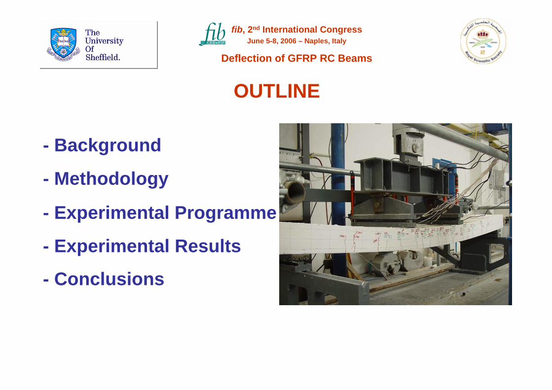
OUTLINE
- Methodology
- Experimental Programme
- Experimental Results
- Background
- Conclusions
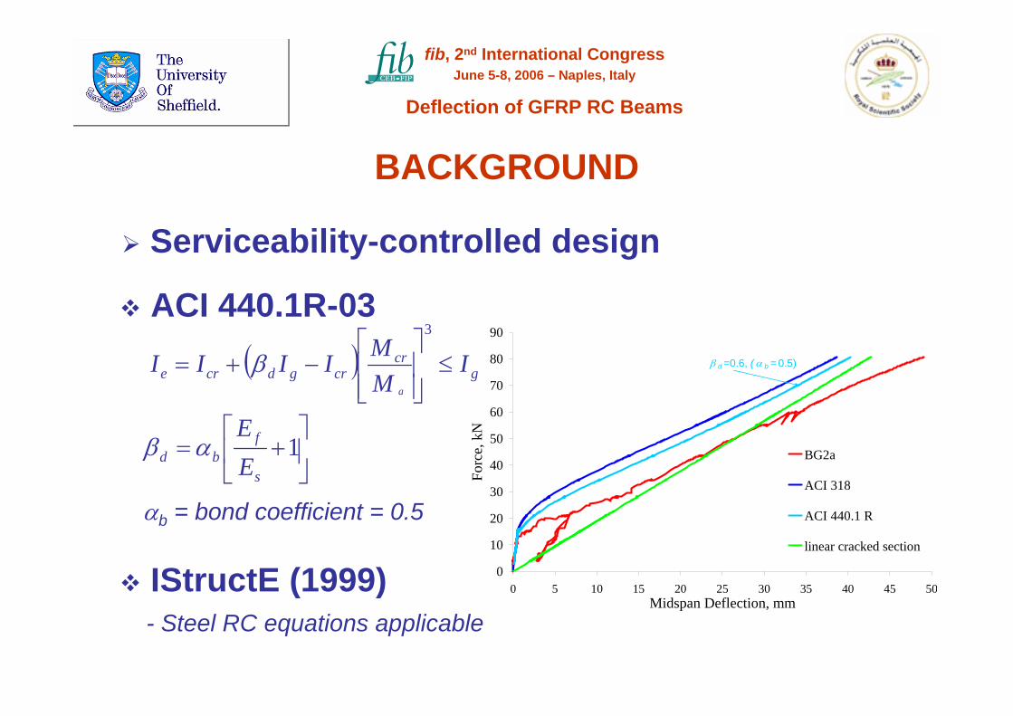
BACKGROUND
Serviceability-controlled design
ACI 440.1R-03
IStructE (1999)- Steel RC equations applicable
( ) gcr
crgdcre IMMIIII
a
≤⎥⎥⎦
⎤
⎢⎢⎣
⎡−+=
3
β
⎥⎦
⎤⎢⎣
⎡+= 1
s
fbd E
Eαβ
αb = bond coefficient = 0.5
0
10
20
30
40
50
60
70
80
90
0 5 10 15 20 25 30 35 40 45 50Midspan Deflection, mm
Forc
e, k
NBG2a
ACI 318
ACI 440.1 R
linear cracked section
β d =0.6, (α b = 0.5)
fib, 2nd International CongressJune 5-8, 2006 – Naples, Italy
Deflection of GFRP RC Beams

Key Variables- Reinforcement Ratio
- Modulus of Elasticity
- Bond Characteristics (Tension Stiffening)
Other Variables- Concrete cover
- Concrete Strength
- Rebar diameter
BACKGROUND
Ribbed
Ribbed
Braided
Indented
Sand coated
Indented
Helically wrapped
fib, 2nd International CongressJune 5-8, 2006 – Naples, Italy
Deflection of GFRP RC Beams
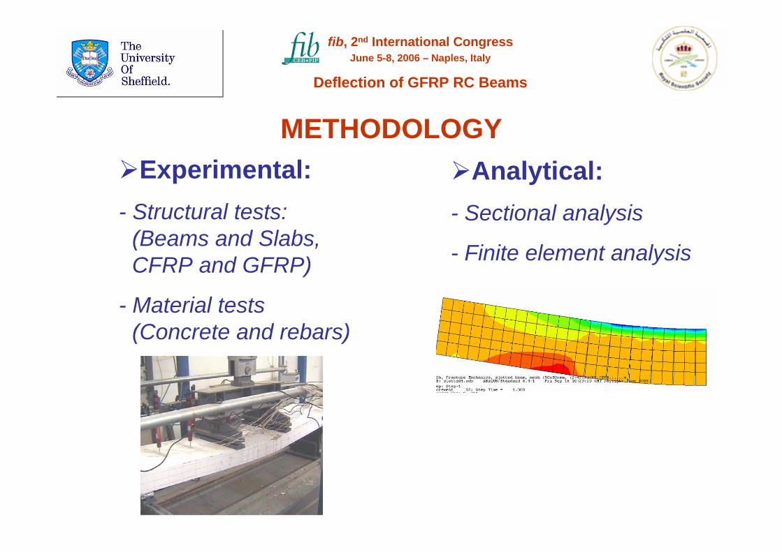
Experimental:- Structural tests:
(Beams and Slabs, CFRP and GFRP)
- Material tests (Concrete and rebars)
Analytical:- Sectional analysis
- Finite element analysis
METHODOLOGY
fib, 2nd International CongressJune 5-8, 2006 – Naples, Italy
Deflection of GFRP RC Beams

76725
0
2300
125
2Ø6mm
125766 767
stirrups,Ø8mm/75mm
2Ø6mm
25m
mto
bar
s
150
stirrups,Ø8mm/75mm
250
EXPERIMENTAL PROGRAMME (GFRP RC Beams)
fib, 2nd International CongressJune 5-8, 2006 – Naples, Italy
Deflection of GFRP RC Beams
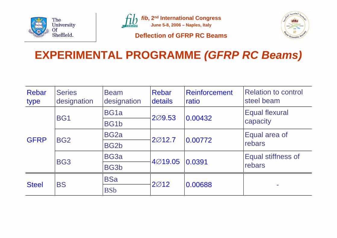
-
Equal stiffness ofrebars
Equal area ofrebars
Equal flexural capacity
Relation to control steel beam
0.00688
0.0391
0.00772
0.00432
Reinforcement ratio
2∅12
4∅19.05
2∅12.7
2∅9.53
Rebar details
BSbBSa
BS
BG3bBG3a
BG3
BG2bBG2a
BG2
BG1bBG1a
BG1
Beam designation
Series designation
Steel
GFRP
Rebar type
fib, 2nd International CongressJune 5-8, 2006 – Naples, Italy
Deflection of GFRP RC Beams
EXPERIMENTAL PROGRAMME (GFRP RC Beams)

6504200019.056004150012.70650425009.53GFRP
Tensile strength, (MPa)
Modulus of elasticity, (MPa)
Nominal diameter,
(mm)
Rebar type
Steel tubeFRP
rebar Epoxy
Plastic end-piece
Grips of tension
machine
fib, 2nd International CongressJune 5-8, 2006 – Naples, Italy
Deflection of GFRP RC Beams
EXPERIMENTAL PROGRAMME (GFRP RC Beams)

1 2 3 4
15
5 6 7 8 9 10 11 12 13 14
Strain Gauge on RebarStrain Gauge on concrete
Midspan forced crack
Anticipated natural crack
90mm
Anticipated natural crack
90mm
18mm 22.5
mm
Detail of 10 strain gauges, No. (5-14), at
midspan zone.
1/3 shear span
Straight arrangement
Helical arrangement
fib, 2nd International CongressJune 5-8, 2006 – Naples, Italy
Deflection of GFRP RC Beams
EXPERIMENTAL PROGRAMME (GFRP RC Beams)
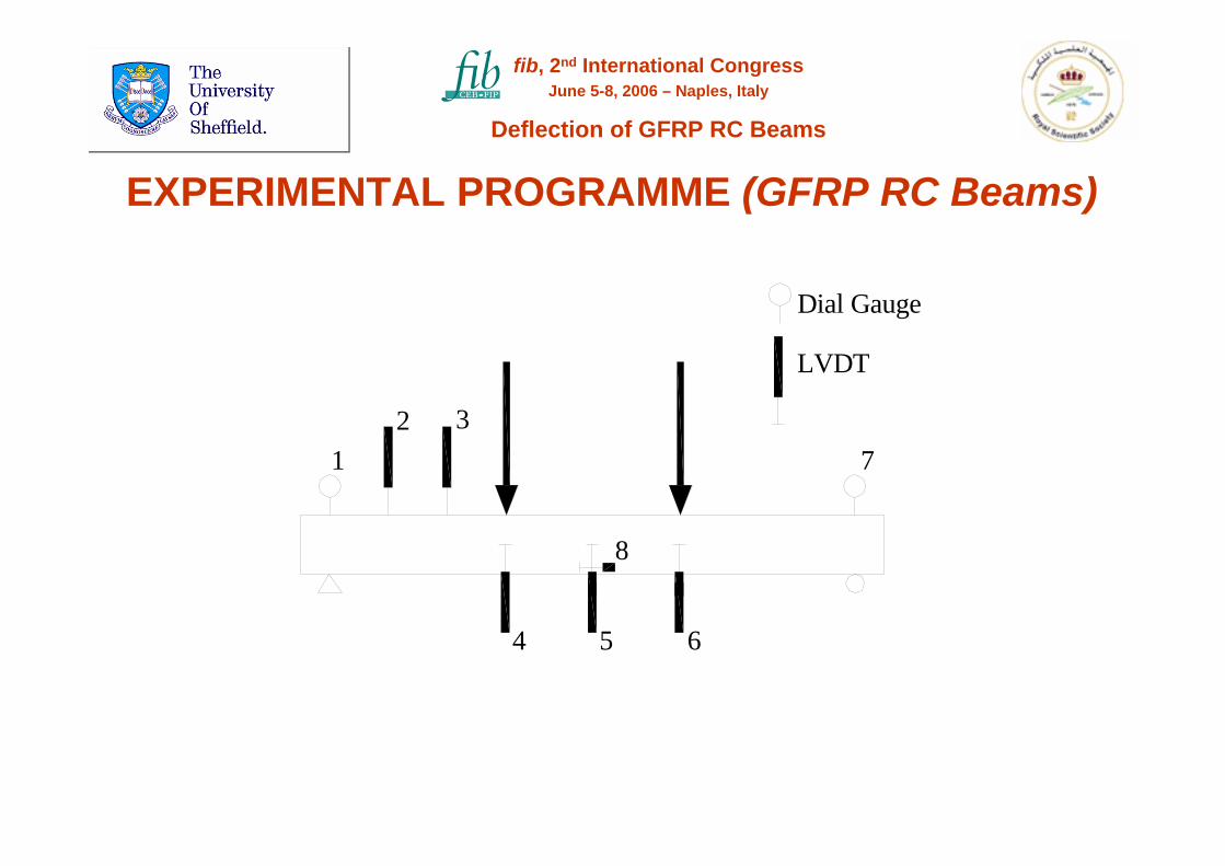
Dial Gauge
LVDT
12 3
4 5
8
7
6
fib, 2nd International CongressJune 5-8, 2006 – Naples, Italy
Deflection of GFRP RC Beams
EXPERIMENTAL PROGRAMME (GFRP RC Beams)

EXPERIMENTAL PROGRAMME (GFRP Beams)
fib, 2nd International CongressJune 5-8, 2006 – Naples, Italy
Deflection of GFRP RC Beams
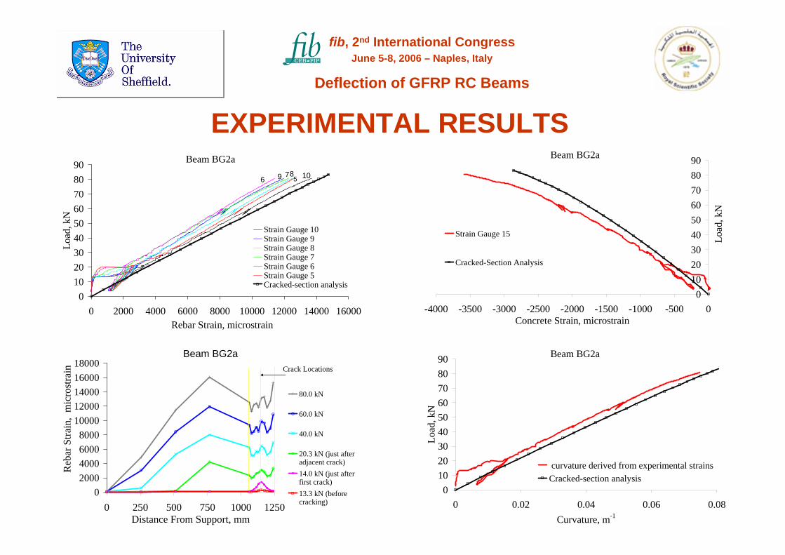
EXPERIMENTAL RESULTS
Beam BG2a
02000400060008000
1000012000140001600018000
0 250 500 750 1000 1250Distance From Support, mm
Reb
ar S
train
, m
icro
stra
in
80.0 kN
60.0 kN
40.0 kN
20.3 kN (just afteradjacent crack)14.0 kN (just afterfirst crack) 13.3 kN (beforecracking)
Crack Locations
Beam BG2a
0102030405060708090
0 2000 4000 6000 8000 10000 12000 14000 16000Rebar Strain, microstrain
Load
, kN
Strain Gauge 10Strain Gauge 9Strain Gauge 8Strain Gauge 7Strain Gauge 6Strain Gauge 5Cracked-section analysis
109 876 5
Beam BG2a
0102030405060708090
-4000 -3500 -3000 -2500 -2000 -1500 -1000 -500 0Concrete Strain, microstrain
Load
, kN
Strain Gauge 15
Cracked-Section Analysis
Beam BG2a
0102030405060708090
0 0.02 0.04 0.06 0.08Curvature, m-1
Load
, kN
curvature derived from experimental strainsCracked-section analysis
fib, 2nd International CongressJune 5-8, 2006 – Naples, Italy
Deflection of GFRP RC Beams
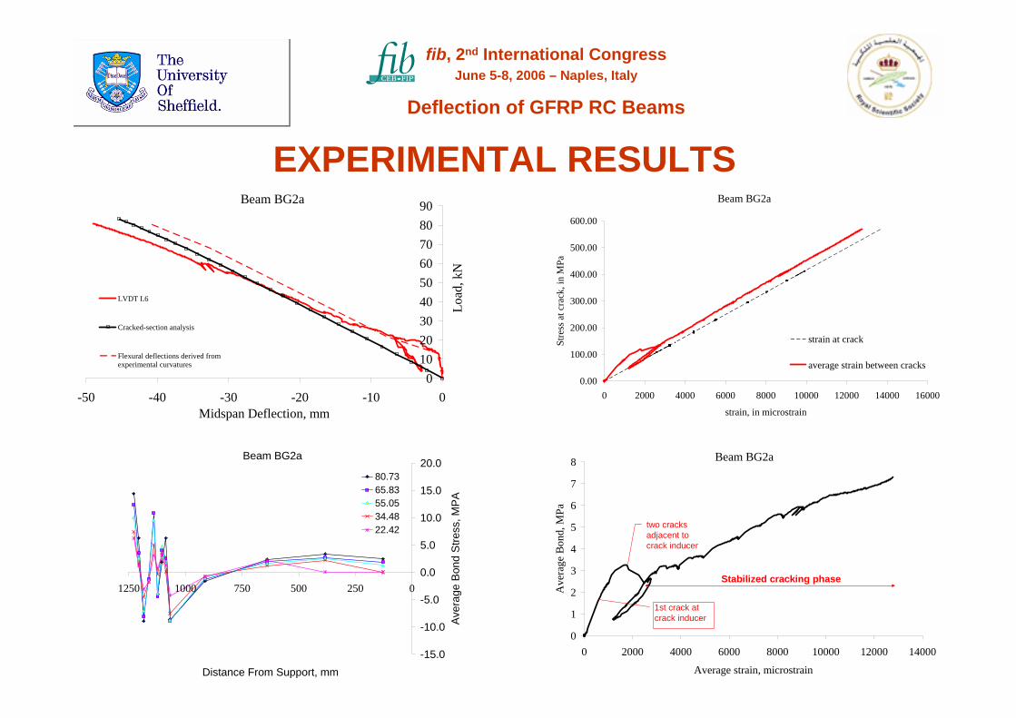
Beam BG2a
0102030405060708090
-50 -40 -30 -20 -10 0Midspan Deflection, mm
Load
, kN
LVDT L6
Cracked-section analysis
Flexural deflections derived fromexperimental curvatures
Beam BG2a
0.00
100.00
200.00
300.00
400.00
500.00
600.00
0 2000 4000 6000 8000 10000 12000 14000 16000
strain, in microstrain
Stre
ss a
t cra
ck, i
n M
Pa
strain at crack
average strain between cracks
Beam BG2a
-15.0
-10.0
-5.0
0.0
5.0
10.0
15.0
20.0
025050075010001250
Distance From Support, mm
Aver
age
Bon
d S
tress
, MPA
80.7365.8355.0534.4822.42
Beam BG2a
0
1
2
3
4
5
6
7
8
0 2000 4000 6000 8000 10000 12000 14000
Average strain, microstrain
Ave
rage
Bon
d, M
Pa
1st crack at crack inducer
two cracks adjacent to crack inducer
Stabilized cracking phase
EXPERIMENTAL RESULTS
fib, 2nd International CongressJune 5-8, 2006 – Naples, Italy
Deflection of GFRP RC Beams

Beam BG2a
0102030405060708090
0 0.5 1 1.5 2 Crack Width, mm
Load
, kN
LVDT L8
calculated from rebar strains
Measured at bottom concretefibre
Load = 20.8 kNAverage crack width = 0.13 mmStandard Deviation = 0.06
Note: Crack widths in flexure zone, at the bottom concrete fibre.
Load = 31.8 kNAverage crack width = 0.19 mmStandard Deviation = 0.06
Load = 47.2 kNAverage crack width = 0.27 mmStandard Deviation = 0.1
Load = 74.7 kNAverage crack width = 0.4 mmStandard Deviation = 0.1
BC2a
BC2a
BC2a
BC2a
EXPERIMENTAL RESULTS
fib, 2nd International CongressJune 5-8, 2006 – Naples, Italy
Deflection of GFRP RC Beams
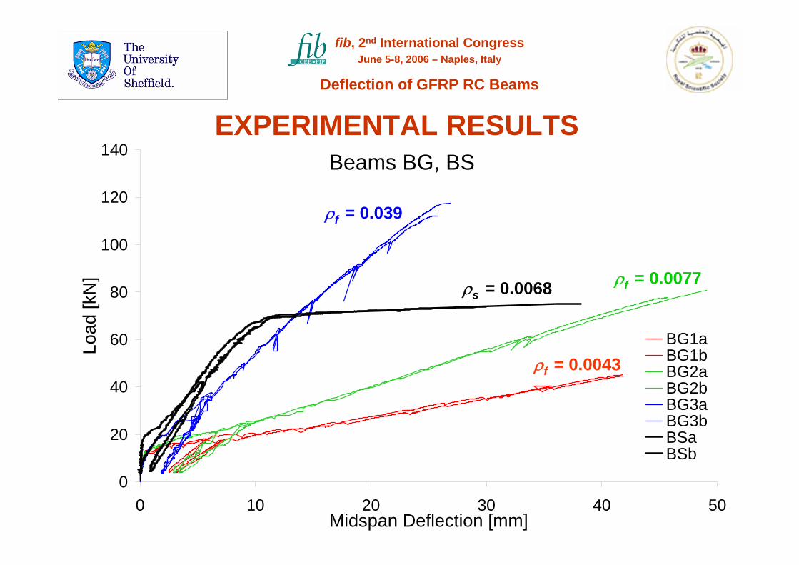
Beams BG, BS
0
20
40
60
80
100
120
140
0 10 20 30 40 50Midspan Deflection [mm]
Load
[kN
]
BG1aBG1bBG2aBG2bBG3aBG3bBSaBSb
ρf = 0.0043
ρf = 0.0077
ρf = 0.039
EXPERIMENTAL RESULTS
ρs = 0.0068
fib, 2nd International CongressJune 5-8, 2006 – Naples, Italy
Deflection of GFRP RC Beams

FINITE ELEMENT ANALYSIS
fib, 2nd International CongressJune 5-8, 2006 – Naples, Italy
Deflection of GFRP RC Beams
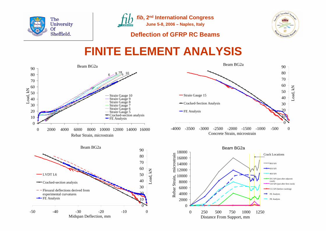
Beam BG2a
0102030405060708090
-50 -40 -30 -20 -10 0Midspan Deflection, mm
Load
, kN
LVDT L6
Cracked-section analysis
Flexural deflections derived fromexperimental curvaturesFE Analysis
Beam BG2a
02000400060008000
1000012000140001600018000
0 250 500 750 1000 1250Distance From Support, mm
Reb
ar S
train
, m
icro
stra
in
80.0 kN
60.0 kN
40.0 kN
20.3 kN (just after adjacentcrack)14.0 kN (just after first crack)
13.3 kN (before cracking)
FE Analysis
FE Analysis
Crack Locations
Beam BG2a
0102030405060708090
0 2000 4000 6000 8000 10000 12000 14000 16000Rebar Strain, microstrain
Load
, kN
Strain Gauge 10Strain Gauge 9Strain Gauge 8Strain Gauge 7Strain Gauge 6Strain Gauge 5Cracked-section analysisFE Analysis
109 876 5
Beam BG2a
0102030405060708090
-4000 -3500 -3000 -2500 -2000 -1500 -1000 -500 0Concrete Strain, microstrain
Load
, kN
Strain Gauge 15
Cracked-Section Analysis
FE Analysis
FINITE ELEMENT ANALYSIS
fib, 2nd International CongressJune 5-8, 2006 – Naples, Italy
Deflection of GFRP RC Beams

CONCLUSIONS
Behaviour of GFRP RC beams:Deflection of GFRP RC is mainly caused by flexural curvatures.
Shear-induced deflections may not be negligible for low reinforcement ratios and deep-penetrating wide cracks.
The response of the compressive concrete zone requires further consideration due to the increased localised effect of cracks.
GFRP RC show good bond.
CSA predicts the maximum rebar strain at a crack, underestimatesthe extreme-fibre concrete strain, and when shear induced deformations are sizeable may not provide an upper-bound deflection.
fib, 2nd International CongressJune 5-8, 2006 – Naples, Italy
Deflection of GFRP RC Beams

ACKNOWLEDGEMENTS
The Higher Council for Science and Technology (Jordan)
The Royal Scientific Society (Jordan)
The University of Sheffield (UK)
The Karim Rida Said Foundation (UK)
fib, 2nd International CongressJune 5-8, 2006 – Naples, Italy
Deflection of GFRP RC Beams